EP0458041B1 - System for controlling a medical treatment, for example dialysis - Google Patents
System for controlling a medical treatment, for example dialysis Download PDFInfo
- Publication number
- EP0458041B1 EP0458041B1 EP91105180A EP91105180A EP0458041B1 EP 0458041 B1 EP0458041 B1 EP 0458041B1 EP 91105180 A EP91105180 A EP 91105180A EP 91105180 A EP91105180 A EP 91105180A EP 0458041 B1 EP0458041 B1 EP 0458041B1
- Authority
- EP
- European Patent Office
- Prior art keywords
- cleaning
- fluid
- vessel
- flow
- treatment
- Prior art date
- Legal status (The legal status is an assumption and is not a legal conclusion. Google has not performed a legal analysis and makes no representation as to the accuracy of the status listed.)
- Revoked
Links
Images

Classifications
-
- A—HUMAN NECESSITIES
- A61—MEDICAL OR VETERINARY SCIENCE; HYGIENE
- A61M—DEVICES FOR INTRODUCING MEDIA INTO, OR ONTO, THE BODY; DEVICES FOR TRANSDUCING BODY MEDIA OR FOR TAKING MEDIA FROM THE BODY; DEVICES FOR PRODUCING OR ENDING SLEEP OR STUPOR
- A61M1/00—Suction or pumping devices for medical purposes; Devices for carrying-off, for treatment of, or for carrying-over, body-liquids; Drainage systems
- A61M1/14—Dialysis systems; Artificial kidneys; Blood oxygenators ; Reciprocating systems for treatment of body fluids, e.g. single needle systems for hemofiltration or pheresis
- A61M1/16—Dialysis systems; Artificial kidneys; Blood oxygenators ; Reciprocating systems for treatment of body fluids, e.g. single needle systems for hemofiltration or pheresis with membranes
- A61M1/168—Sterilisation or cleaning before or after use
- A61M1/169—Sterilisation or cleaning before or after use using chemical substances
-
- A—HUMAN NECESSITIES
- A61—MEDICAL OR VETERINARY SCIENCE; HYGIENE
- A61M—DEVICES FOR INTRODUCING MEDIA INTO, OR ONTO, THE BODY; DEVICES FOR TRANSDUCING BODY MEDIA OR FOR TAKING MEDIA FROM THE BODY; DEVICES FOR PRODUCING OR ENDING SLEEP OR STUPOR
- A61M1/00—Suction or pumping devices for medical purposes; Devices for carrying-off, for treatment of, or for carrying-over, body-liquids; Drainage systems
- A61M1/14—Dialysis systems; Artificial kidneys; Blood oxygenators ; Reciprocating systems for treatment of body fluids, e.g. single needle systems for hemofiltration or pheresis
- A61M1/16—Dialysis systems; Artificial kidneys; Blood oxygenators ; Reciprocating systems for treatment of body fluids, e.g. single needle systems for hemofiltration or pheresis with membranes
- A61M1/1654—Dialysates therefor
- A61M1/1656—Apparatus for preparing dialysates
- A61M1/1666—Apparatus for preparing dialysates by dissolving solids
-
- A—HUMAN NECESSITIES
- A61—MEDICAL OR VETERINARY SCIENCE; HYGIENE
- A61M—DEVICES FOR INTRODUCING MEDIA INTO, OR ONTO, THE BODY; DEVICES FOR TRANSDUCING BODY MEDIA OR FOR TAKING MEDIA FROM THE BODY; DEVICES FOR PRODUCING OR ENDING SLEEP OR STUPOR
- A61M1/00—Suction or pumping devices for medical purposes; Devices for carrying-off, for treatment of, or for carrying-over, body-liquids; Drainage systems
- A61M1/14—Dialysis systems; Artificial kidneys; Blood oxygenators ; Reciprocating systems for treatment of body fluids, e.g. single needle systems for hemofiltration or pheresis
- A61M1/16—Dialysis systems; Artificial kidneys; Blood oxygenators ; Reciprocating systems for treatment of body fluids, e.g. single needle systems for hemofiltration or pheresis with membranes
- A61M1/168—Sterilisation or cleaning before or after use
- A61M1/1682—Sterilisation or cleaning before or after use both machine and membrane module, i.e. also the module blood side
-
- A—HUMAN NECESSITIES
- A61—MEDICAL OR VETERINARY SCIENCE; HYGIENE
- A61M—DEVICES FOR INTRODUCING MEDIA INTO, OR ONTO, THE BODY; DEVICES FOR TRANSDUCING BODY MEDIA OR FOR TAKING MEDIA FROM THE BODY; DEVICES FOR PRODUCING OR ENDING SLEEP OR STUPOR
- A61M1/00—Suction or pumping devices for medical purposes; Devices for carrying-off, for treatment of, or for carrying-over, body-liquids; Drainage systems
- A61M1/14—Dialysis systems; Artificial kidneys; Blood oxygenators ; Reciprocating systems for treatment of body fluids, e.g. single needle systems for hemofiltration or pheresis
- A61M1/16—Dialysis systems; Artificial kidneys; Blood oxygenators ; Reciprocating systems for treatment of body fluids, e.g. single needle systems for hemofiltration or pheresis with membranes
- A61M1/168—Sterilisation or cleaning before or after use
- A61M1/1686—Sterilisation or cleaning before or after use by heat
-
- A—HUMAN NECESSITIES
- A61—MEDICAL OR VETERINARY SCIENCE; HYGIENE
- A61M—DEVICES FOR INTRODUCING MEDIA INTO, OR ONTO, THE BODY; DEVICES FOR TRANSDUCING BODY MEDIA OR FOR TAKING MEDIA FROM THE BODY; DEVICES FOR PRODUCING OR ENDING SLEEP OR STUPOR
- A61M1/00—Suction or pumping devices for medical purposes; Devices for carrying-off, for treatment of, or for carrying-over, body-liquids; Drainage systems
- A61M1/14—Dialysis systems; Artificial kidneys; Blood oxygenators ; Reciprocating systems for treatment of body fluids, e.g. single needle systems for hemofiltration or pheresis
- A61M1/16—Dialysis systems; Artificial kidneys; Blood oxygenators ; Reciprocating systems for treatment of body fluids, e.g. single needle systems for hemofiltration or pheresis with membranes
- A61M1/168—Sterilisation or cleaning before or after use
- A61M1/1688—Sterilisation or cleaning before or after use with recirculation of the sterilising fluid
-
- A—HUMAN NECESSITIES
- A61—MEDICAL OR VETERINARY SCIENCE; HYGIENE
- A61M—DEVICES FOR INTRODUCING MEDIA INTO, OR ONTO, THE BODY; DEVICES FOR TRANSDUCING BODY MEDIA OR FOR TAKING MEDIA FROM THE BODY; DEVICES FOR PRODUCING OR ENDING SLEEP OR STUPOR
- A61M1/00—Suction or pumping devices for medical purposes; Devices for carrying-off, for treatment of, or for carrying-over, body-liquids; Drainage systems
- A61M1/14—Dialysis systems; Artificial kidneys; Blood oxygenators ; Reciprocating systems for treatment of body fluids, e.g. single needle systems for hemofiltration or pheresis
- A61M1/16—Dialysis systems; Artificial kidneys; Blood oxygenators ; Reciprocating systems for treatment of body fluids, e.g. single needle systems for hemofiltration or pheresis with membranes
- A61M1/168—Sterilisation or cleaning before or after use
-
- A—HUMAN NECESSITIES
- A61—MEDICAL OR VETERINARY SCIENCE; HYGIENE
- A61M—DEVICES FOR INTRODUCING MEDIA INTO, OR ONTO, THE BODY; DEVICES FOR TRANSDUCING BODY MEDIA OR FOR TAKING MEDIA FROM THE BODY; DEVICES FOR PRODUCING OR ENDING SLEEP OR STUPOR
- A61M2209/00—Ancillary equipment
- A61M2209/08—Supports for equipment
- A61M2209/082—Mounting brackets, arm supports for equipment
Definitions
- the present invention relates to a medical treatment apparatus, for example an apparatus for dialysis, using a preferably heated treatment fluid, comprising conditioning means for preparing and controlling the fluid and flowing it through a flow path and connection means for connecting the apparatus to a treatment device, for example a dialyzer. Cleaning of the apparatus is effected with a cleaning fluid which is made to flow along the same path as the treatment fluid, except for said treatment device.
- the apparatus according to the invention is intended for preparation of dialysis fluid in connection with haemodialysis. With minor modifications it can also, however, be used for preparation of replacement fluid in connection with haemofiltration or haemodiafiltration. It will be evident to the skilled man that the apparatus can also be used in connection with many other medical treatment methods where a treatment fluid is utilized or such a fluid is produced, for example wound rinsing fluid.
- a treatment fluid based on bicarbonate was originally used for dialysis. When the systems and monitors for this were later automated, difficulties arose, amongst them, precipitation. Other treatment fluids were therefore used instead, for example fluids based on acetate. Recently bicarbonate-based liquids have again found favour, at the same time the mentioned problems have in the main been overcome. However, certain problems still remain regarding precipitation. Thus, apparatuses in use must be cleaned at regular intervals. Hitherto this has been achieved by rinsing the systems with the aid of a cleaning liquid, for example citric acid.
- a cleaning liquid for example citric acid.
- US Patent No. 4 728 496 discloses an apparatus and a method for sterilization of, by way of example, a dialysis monitor. According to this system a fluid such as water is recirculated and heated within a part of the apparatus preceding the dialyzer. As is explained in the following, this apparatus can, after certain amendments, also be used for the application of the present invention.
- US Patent No. 4 784 495 discloses a system for preparing a fluid intended for a medical procedure, for example dialysis, wherein the treatment fluid is prepared from a concentrate in powder form, for example sodium bicarbonate. Even in this system the present invention can be advantageously applied.
- US Patent No. 4 789 467 discloses an automated disinfection system for a hemodialysis machine, having a container filled with a disinfection solution. A coupling tip is provided for connection to a check valve forming a part of hemodialysis machine. The liquid disinfection solution is introduced in the ordinary treatment path of the system.
- An object of the present invention is to provide a medical treatment apparatus in which cleaning by a cleaning agent, such as a chemical agent, can be performed in a simple manner.
- Another object of the present invention is to obtain disinfection and/or sterilization of said medical treatment apparatus by combined heat disinfection and chemical disinfection.
- a further object of the present invention is to obtain effective cleaning of a part of the medical treatment apparatus preceding the treatment device.
- a still further object of the invention is to provide a medical treatment apparatus in which the cleaning agent is prvoided in a convenient way in a vessel or cartridge comprising the cleaning agent in a quantity sufficient for one cleaning operation.
- a medical treatment apparatus intended for preparation and/or administration of a treatment fluid, for example an apparatus for dialysis.
- the apparatus comprises an inlet for introducing a fluid, preferably essentially water, into a conduit of the apparatus, conditioning means for preparing and/or controlling said fluid for forming said treatment fluid and/or for flowing said treatment fluid through a flow path of said apparatus; connection means for connecting the apparatus to a treatment device, for example a dialyzer, for supplying said treatment fluid to said treatment device; and introduction means for introducing a cleaning fluid into said apparatus and for flowing said cleaning fluid along essentially the same flow path as the treatment fluid, except for said treatment device, for cleaning the apparatus.
- the apparatus comprises a vessel containing a cleaning agent in concentrated liquid or powder form, which achieves or at least aids said cleaning, said vessel being connected to supply means for supplying a solvent to said vessel whereby said solvent enters the vessel for mixing with the cleaning agent for diluting and/or dissolution of said cleaning agent for forming said cleaning fluid and the vessel also being connected to the introduction means.
- the vessel comprises an inlet for introducing said solvent into said vessel and an outlet for connection to said introduction means.
- the supply means for supplying a solvent is a means for supplying water.
- the apparatus comprises recirculation means for recirculating at least a portion of the cleaning fluid through a recirculation path comprising a heating device for increasing and essentially maintaining the temperature of the cleaning fluid at a predetermined temperature, for example a little over 90°C, and flow means for flowing the cleaning fluid thorugh a non-recirculation path, wherein the temperature of the cleaning fluid is allowed to gradually decrease to a lower predetermined value, for example 80°.
- the non-recirculation path is a portion of said flow path downstreams of said connection means.
- the vessel comprises the cleaning agent in a quantity sufficient for one cleaning operation.
- the cleaning agent can be citric acid, peracetic acid, oxalic acid, sodium hydroxide, sodium hypochloride, sodium carbonate or suitable combinations thereof.
- Fig. 1 is a schematic view of an apparatus designed according to the invention.
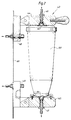
- Fig. 2 is a cross-sectional view showing means for connecting a concentrate cartridge or other vessel to the apparatus according to Fig. 1.
- Fig. 1 shows a preferred embodiment of a system or apparatus according to the invention.
- water is supplied via an inlet 1a through a water conduit 1 to a heating device 2 for heating.
- a heating device 2 for heating.
- Fig. 1 three various possible connection positions 1', 1'' respectively 1''' are shown for the above mentioned cartridge or other vessel containing a cleaning or cleansing concentrate.
- the same cartridge is shown in Fig. 2 with reference 10f together with means for its connection.
- Water is taken from the heating device 2 with or without cleansing concentrate via a temperature measuring device 3, a return vessel 4, a throttle 5, a bubble-expansion chamber 6, a pressure measuring device 7 and a pump 8 to a ventilating chamber 9.
- a return conduit 10 leads from the ventilating chamber 9 back to the return vessel 4 for returning separated air or other gases together with a small quantity of fluid.
- a return line to the heating vessel 2 could instead be provided, but this would, however, require the use of chemically resistant material, since dialysis concentrate is normally supplied to the point 11 via conduit 12 with the help of the pump 13. This part of the system corresponds in the main with the system which is described by way of example in US Patents Nos. 4 158 034 and 4 293 409.
- the pressure measured by the pressure measuring device 21 is used for controlling the pump 20 so that a desired constant flow is achieved.
- the flow is led through a conductivity measurer 22 and ultra-filtration control 23 via a temperature measurer 24 and a pressure measurer 25 to a dialyser 33.
- a pressure measurer 26 said ultra-filtration control 23 and a blood detector 27 to a further constant flow device 28 comprising a pump 29, a pressure measurer 30 and a throttle device 31.
- the dialysate is led to an outlet 32.
- Figure reference numeral 33 denotes the dialyzer connectable to the system according to the invention, to whose blood-side the patient is connected. This latter connection is, however, not shown in Figure 1.
- the dialyzer 33 can be by-passed in two ways. This can occur either with the aid of by-pass conduit 34 with valve 35, which opens, for example if the temperature or the conductivity exceeds or falls below predetermined level. At the same time, the flow to the dialyzer is interrupted with the help of a not shown valve.
- the by-pass can occur by means of the dialyzer connections 36 and 37 being connected to a by-pass conduit 38 via connections 39 and 40.
- This by-pass arrangement is principally designed according to US Patent No. 4 122 010 with a pressure monitoring device 41 which detects if a positive or negative pressure arises in conduit 38. If such is the case, and only then, sterilizing and/or cleansing can take place. Thus, treatment operation and cleansing operation can not be confused.
- a return conduit 42 with a valve 43 extends from the by-pass arrangement 38 back to the heating vessel 2.
- a quantity of the flow recirculates through this conduit 42 when the system is to be disinfected and/or sterilized and/or cleansed in any other way.
- the remainder of the flow is instead led from conduit 36 which is connected to connector 39 via conduit 38 and connector 40 to the conduit 37 and from there through the ultra-filtration control 23 and further to the outlet 32.
- a smaller quantity is, however, led directly from the conduit 36 via the conduit 34 with the valve 35 directly to the conduit 37 for cleansing of the by-pass connection.
- a cartridge or other vessel containing a cleansing concentrate is connected at 1', 1'' or 1'''.
- An example of such a connection is shown in Figure 2.
- the cartridge consists here of a closed vessel 10f which is provided at its ends with penetrable membranes 62 and 64. In this way, the cartridge is completely sealed so that the cleansing concentrate is not contaminated and can not escape the cartridge until the membranes are penetrated.
- the cartridge 10f and means for its connection to the system according to the invention can be designed totally in accordance with the above mentioned US Patent No. 4 784 495.
- the differance is solely that the cartridge shall contain a cleansing concentrate instead of a treatment concentrate.
- the cartridge 10f is thus connected to the system with the aid of penetrating nippels 46 and 47 which are arranged on two lever arms 44 and 45. Fluid is supplied via nippel 46 and removed via nippel 47.
- the idea behind the lever arms 44 and 45 is that the system can also be used without a cartridge.
- the lever arms are swung to a position such that the nippels 46 and 47 are connected instead to a by-pass conduit connected to two nippels 48 and 49.
- These nippels like the lever arms 44 and 45, are fixed to the wall 60 of a not shown control-monitor, for example such as used for controlling dialysis.
- Examples of applicable cleansing agents can be: citric acid, acetic acid, peracetic acid, oxalic acid, sodium hydroxide, sodium hypochloride, sodium carbonates or suitable combinations thereof, though preferably citric acid.
- citric acid a suitable solution is obtained when 40 grams of citric acid is dissolved in two litres of water to a concentration of two per cent.
- the citric acid can be "spiked" with oxalic acid. In this way any iron and copper precipitations are dissolved.
- a water solution can be used containing sixteen per cent citric acid and four per cent oxalic acid. This gives a very effective cleansing.
- a further alternative is the use of a water solution comprising 150 g/l sodium hypochloride, 4 g/l sodium hydroxide and 10-25 g/l of sodium carbonate which gives an effective cleansing after suitable dilution (approx. 20 times).
- the utilized concentrate cartridge can be connected at the beginning of the cleansing program and remain so during the whole of the rinsing program, which always follows the cleansing. This makes handling simpler. Cleansing agents which are harmless for the patient can be used. For example, citric acid is a basic food stuff and, as such, any small remnents are harmless for the patient. An important advantage is also the possibility to use various cleansing agents suited to respective treatment systems and conditions of use. The function of the system itself is also safer through effective cleansing. For dialysis, the necessary program change in existing programs is very slight.
Description
- The present invention relates to a medical treatment apparatus, for example an apparatus for dialysis, using a preferably heated treatment fluid, comprising conditioning means for preparing and controlling the fluid and flowing it through a flow path and connection means for connecting the apparatus to a treatment device, for example a dialyzer. Cleaning of the apparatus is effected with a cleaning fluid which is made to flow along the same path as the treatment fluid, except for said treatment device.
- Preferably, the apparatus according to the invention is intended for preparation of dialysis fluid in connection with haemodialysis. With minor modifications it can also, however, be used for preparation of replacement fluid in connection with haemofiltration or haemodiafiltration. It will be evident to the skilled man that the apparatus can also be used in connection with many other medical treatment methods where a treatment fluid is utilized or such a fluid is produced, for example wound rinsing fluid.
- A treatment fluid based on bicarbonate was originally used for dialysis. When the systems and monitors for this were later automated, difficulties arose, amongst them, precipitation. Other treatment fluids were therefore used instead, for example fluids based on acetate. Recently bicarbonate-based liquids have again found favour, at the same time the mentioned problems have in the main been overcome. However, certain problems still remain regarding precipitation. Thus, apparatuses in use must be cleaned at regular intervals. Hitherto this has been achieved by rinsing the systems with the aid of a cleaning liquid, for example citric acid.
- US Patent No. 4 728 496 discloses an apparatus and a method for sterilization of, by way of example, a dialysis monitor. According to this system a fluid such as water is recirculated and heated within a part of the apparatus preceding the dialyzer. As is explained in the following, this apparatus can, after certain amendments, also be used for the application of the present invention.
- US Patent No. 4 784 495 discloses a system for preparing a fluid intended for a medical procedure, for example dialysis, wherein the treatment fluid is prepared from a concentrate in powder form, for example sodium bicarbonate. Even in this system the present invention can be advantageously applied.
- US Patent No. 4 789 467 discloses an automated disinfection system for a hemodialysis machine, having a container filled with a disinfection solution. A coupling tip is provided for connection to a check valve forming a part of hemodialysis machine. The liquid disinfection solution is introduced in the ordinary treatment path of the system.
- An object of the present invention is to provide a medical treatment apparatus in which cleaning by a cleaning agent, such as a chemical agent, can be performed in a simple manner.
- Another object of the present invention is to obtain disinfection and/or sterilization of said medical treatment apparatus by combined heat disinfection and chemical disinfection.
- A further object of the present invention is to obtain effective cleaning of a part of the medical treatment apparatus preceding the treatment device.
- A still further object of the invention is to provide a medical treatment apparatus in which the cleaning agent is prvoided in a convenient way in a vessel or cartridge comprising the cleaning agent in a quantity sufficient for one cleaning operation.
- Still further objects appear from the ensuing description.
- Accordingly, there is provided a medical treatment apparatus intended for preparation and/or administration of a treatment fluid, for example an apparatus for dialysis. The apparatus comprises an inlet for introducing a fluid, preferably essentially water, into a conduit of the apparatus, conditioning means for preparing and/or controlling said fluid for forming said treatment fluid and/or for flowing said treatment fluid through a flow path of said apparatus; connection means for connecting the apparatus to a treatment device, for example a dialyzer, for supplying said treatment fluid to said treatment device; and introduction means for introducing a cleaning fluid into said apparatus and for flowing said cleaning fluid along essentially the same flow path as the treatment fluid, except for said treatment device, for cleaning the apparatus.
- According to the invention the apparatus comprises a vessel containing a cleaning agent in concentrated liquid or powder form, which achieves or at least aids said cleaning, said vessel being connected to supply means for supplying a solvent to said vessel whereby said solvent enters the vessel for mixing with the cleaning agent for diluting and/or dissolution of said cleaning agent for forming said cleaning fluid and the vessel also being connected to the introduction means. The vessel comprises an inlet for introducing said solvent into said vessel and an outlet for connection to said introduction means. Preferably, the supply means for supplying a solvent is a means for supplying water.
- In a preferred embodiment, the apparatus comprises recirculation means for recirculating at least a portion of the cleaning fluid through a recirculation path comprising a heating device for increasing and essentially maintaining the temperature of the cleaning fluid at a predetermined temperature, for example a little over 90°C, and flow means for flowing the cleaning fluid thorugh a non-recirculation path, wherein the temperature of the cleaning fluid is allowed to gradually decrease to a lower predetermined value, for example 80°. Preferably, the non-recirculation path is a portion of said flow path downstreams of said connection means.
- In the preferred embodiment, the vessel comprises the cleaning agent in a quantity sufficient for one cleaning operation. The cleaning agent can be citric acid, peracetic acid, oxalic acid, sodium hydroxide, sodium hypochloride, sodium carbonate or suitable combinations thereof.
- Further objects and advantages appear from the following description of a preferred embodiment of the invention with reference to the drawings.
- Fig. 1 is a schematic view of an apparatus designed according to the invention.
- Fig. 2 is a cross-sectional view showing means for connecting a concentrate cartridge or other vessel to the apparatus according to Fig. 1.
- Fig. 1 shows a preferred embodiment of a system or apparatus according to the invention. In the system water is supplied via an inlet 1a through a water conduit 1 to a heating device 2 for heating. In Fig. 1 three various possible connection positions 1', 1'' respectively 1''' are shown for the above mentioned cartridge or other vessel containing a cleaning or cleansing concentrate. The same cartridge is shown in Fig. 2 with
reference 10f together with means for its connection. - Water is taken from the heating device 2 with or without cleansing concentrate via a temperature measuring device 3, a
return vessel 4, athrottle 5, a bubble-expansion chamber 6, a pressure measuring device 7 and apump 8 to a ventilating chamber 9. Areturn conduit 10 leads from the ventilating chamber 9 back to thereturn vessel 4 for returning separated air or other gases together with a small quantity of fluid. A return line to the heating vessel 2 could instead be provided, but this would, however, require the use of chemically resistant material, since dialysis concentrate is normally supplied to thepoint 11 viaconduit 12 with the help of thepump 13. This part of the system corresponds in the main with the system which is described by way of example in US Patents Nos. 4 158 034 and 4 293 409. The operation of theexpansion chamber 6 is described in more detail in US Patent No. 4 536 201. Fluid is led from the ventilating chamber 9 via aconductivity measuring cell 14 to afurther mixing point 15 where any additional concentrate is supplied with the aid of thepump 16 and aconduit 17. This is on the assumption that a so called two-component-based dialysis concentrate is to be used, for example of the type which is described in EP-B-O 022 922. Dialysis fluid is led from themixing point 15 through a firstconstant flow device 18 comprising athrottle 19, apump 20 and apressure measuring device 21. - The pressure measured by the
pressure measuring device 21 is used for controlling thepump 20 so that a desired constant flow is achieved. After thepump 20 the flow is led through aconductivity measurer 22 andultra-filtration control 23 via atemperature measurer 24 and apressure measurer 25 to adialyser 33. From there the flow is normally led via apressure measurer 26, saidultra-filtration control 23 and ablood detector 27 to a furtherconstant flow device 28 comprising apump 29, apressure measurer 30 and athrottle device 31. Finally, the dialysate is led to anoutlet 32. - The construction and function of the ultra-filtration control is described in more detail in GB-B-2 003 274 and EP-B-0 106 940.
Figure reference numeral 33 denotes the dialyzer connectable to the system according to the invention, to whose blood-side the patient is connected. This latter connection is, however, not shown in Figure 1. - The
dialyzer 33 can be by-passed in two ways. This can occur either with the aid of by-pass conduit 34 withvalve 35, which opens, for example if the temperature or the conductivity exceeds or falls below predetermined level. At the same time, the flow to the dialyzer is interrupted with the help of a not shown valve. - Alternatively, the by-pass can occur by means of the
dialyzer connections pass conduit 38 viaconnections conduit 38. If such is the case, and only then, sterilizing and/or cleansing can take place. Thus, treatment operation and cleansing operation can not be confused. - In the shown example a
return conduit 42 with avalve 43 extends from the by-pass arrangement 38 back to the heating vessel 2. A quantity of the flow recirculates through thisconduit 42 when the system is to be disinfected and/or sterilized and/or cleansed in any other way. The remainder of the flow is instead led fromconduit 36 which is connected toconnector 39 viaconduit 38 andconnector 40 to theconduit 37 and from there through theultra-filtration control 23 and further to theoutlet 32. A smaller quantity is, however, led directly from theconduit 36 via theconduit 34 with thevalve 35 directly to theconduit 37 for cleansing of the by-pass connection. - According to the invention a cartridge or other vessel containing a cleansing concentrate is connected at 1', 1'' or 1'''. An example of such a connection is shown in Figure 2. The cartridge consists here of a
closed vessel 10f which is provided at its ends withpenetrable membranes - The
cartridge 10f and means for its connection to the system according to the invention can be designed totally in accordance with the above mentioned US Patent No. 4 784 495. The differance is solely that the cartridge shall contain a cleansing concentrate instead of a treatment concentrate. Thecartridge 10f is thus connected to the system with the aid of penetratingnippels lever arms nippel 46 and removed vianippel 47. The idea behind thelever arms nippels lever arms wall 60 of a not shown control-monitor, for example such as used for controlling dialysis. - Examples of applicable cleansing agents can be: citric acid, acetic acid, peracetic acid, oxalic acid, sodium hydroxide, sodium hypochloride, sodium carbonates or suitable combinations thereof, though preferably citric acid. When citric acid is used, a suitable solution is obtained when 40 grams of citric acid is dissolved in two litres of water to a concentration of two per cent.
- Alternatively, the citric acid can be "spiked" with oxalic acid. In this way any iron and copper precipitations are dissolved. By way of example a water solution can be used containing sixteen per cent citric acid and four per cent oxalic acid. This gives a very effective cleansing. A further alternative is the use of a water solution comprising 150 g/l sodium hypochloride, 4 g/l sodium hydroxide and 10-25 g/l of sodium carbonate which gives an effective cleansing after suitable dilution (approx. 20 times).
- The above-mentioned solutions can be prepared in advance. Preferably, however, they are prepared directly in the system since the connected cartridge contains the concentrates in powder form.
- Many advantages are obtained with the invention. In addition to the above-mentioned advantages, no mixing of the cleansing solution is needed in the clinic or pharmacy. Instead this can take place directly in the system. The possibility of using powder concentrate offers weight-saving advantages. However, not all concentrates need to be in powder form, since it is important that the invention can also be used with the aid of liquid-based concentrates.
- The utilized concentrate cartridge can be connected at the beginning of the cleansing program and remain so during the whole of the rinsing program, which always follows the cleansing. This makes handling simpler. Cleansing agents which are harmless for the patient can be used. For example, citric acid is a basic food stuff and, as such, any small remnents are harmless for the patient. An important advantage is also the possibility to use various cleansing agents suited to respective treatment systems and conditions of use. The function of the system itself is also safer through effective cleansing. For dialysis, the necessary program change in existing programs is very slight.
- Naturally, the invention is not restriced to the above described examples, but can be varied within the scope of the appended claims. For example, the shown details can be varied within wide limits of form and function.
Claims (14)
- A medical treatment apparatus intended for preparation and/or administration of a treatment fluid, for example an apparatus for dialysis, said apparatus comprising:
an inlet (1a) for introducing a fluid, preferably essentially water, into a conduit (1) of the apparatus,
conditioning means (2 - 22) for preparing and/or controlling said fluid for forming said treatment fluid and/or for flowing said treatment fluid through a flow path of said apparatus;
connection means (36,37) for connecting the apparatus to a treatment device (33), for example a dialyzer, for supplying said treatment fluid to said treatment device; and
introduction means (1,8;12,13;16,17) for introducing a cleaning fluid into said apparatus and for flowing said cleaning fluid along essentially the same flow path as the treatment fluid, except for said treatment device (33), for cleaning the apparatus;
characterized by
a vessel (1', 1'', 1''') containing a cleaning agent in concentrated liquid or powder form, which achieves or at least aids said cleaning, said vessel being connected to supply means (1a) for supplying a solvent to said vessel whereby said solvent enters the vessel for mixing with said cleaning agent for diluting and/or dissolution of said cleaning agent for forming said cleaning fluid and the vessel also being connected to the introduction means. - Apparatus according to claim 1, characterized in that said vessel (1',1'',1''') comprises an inlet for introducing said solvent into said vessel and an outlet for connection to said introduction means.
- Apparatus according to claim 1 or 2, characterized in that said supply means (1a) for supplying a solvent is a means for supplying water.
- Apparatus according to claim 1, 2 or 3, characterized by recirculation means (39 - 43) for recirculating at least a portion of said cleaning fluid present in said flow path through a recirculation path from a position downstreams in said flow path and to a position (2) adjacent said first inlet (1a).
- Apparatus according to claim 1, 2 or 3, wherein said apparatus comprises a heating device (2) for heating said treatment fluid, characterized by recirculation means (39 - 43) for recirculating at least a portion of said cleaning fluid present in said flow path through a recirculation path comprising said heating device (2) for increasing and essentially maintaining the temperature of said cleaning fluid at a predetermined temperature, for exampel a little over 90°C, and flow means (37,29,32) for flowing said cleaning fluid through a non-recirculation path, wherein the temperature of said cleaning fluid is allowed to gradually decrease to a lower predetermined value, for example 80°C.
- Apparatus according to claim 5, characterized in that said non-recirculation path is a portion of said flow path downstreams of said connection means (36,37).
- Apparatus according to claim 5 or 6, characterized in that recirculation flow means (8,20) in the recirculation path is adapted to flow said cleaning fluid at a high first flow speed, and that said flow means (29) in the non-recirculation path is adapted to flow said cleaning fluid at a low second flow speed, for example, one fifth of the first flow speed.
- Apparatus according to any one of the preceding claims, wherein said conditioning means of the apparatus comprises control means (5,6,9,14,19,22,23,27,31), for example throttles, included in said flow path, characterized by actuation means adapted to, during cleaning, opening and/or completely or partially by-passing said control means for reducing the flow-resistances thereof.
- Apparatus according to any one of the preceding claims, characterized in that said cleaning operation takes place at substantially normal atmospheric pressure.
- Apparatus according to any one of the preceding claims, characterized in that said vessel comprises said cleaning agent in a quantity sufficient for one cleaning operation.
- Apparatus according to claim 10, characterized in that the vessel is completely sealed and is provided with penetrable membranes at its inlet and outlet.
- Apparatus according to claim 10 or 11, characterized in that the vessel contains one of the following concentrates: citric acid, peracetic acid, oxalic acid, sodium hydroxide, sodium hypochloride, sodium carbonate or suitable combinations thereof.
- Apparatus according to any one of claims 10-12, characterized in that said cleaning agent is a powder and is citric acid in crystalline form.
- Apparatus according to any one of claims 10-13, characterized in that said vessel is a cartridge.
Priority Applications (1)
| Application Number | Priority Date | Filing Date | Title |
|---|---|---|---|
| EP95103615A EP0673658A1 (en) | 1990-05-25 | 1991-04-02 | System for controlling a medical treatment, for example dialysis |
Applications Claiming Priority (2)
| Application Number | Priority Date | Filing Date | Title |
|---|---|---|---|
| SE9001890 | 1990-05-25 | ||
| SE9001890A SE9001890L (en) | 1990-05-25 | 1990-05-25 | SYSTEM FOR MANAGING A MEDICAL TREATMENT, TEX DIALYSIS |
Related Child Applications (1)
| Application Number | Title | Priority Date | Filing Date |
|---|---|---|---|
| EP95103615.1 Division-Into | 1995-03-14 |
Publications (2)
| Publication Number | Publication Date |
|---|---|
| EP0458041A1 EP0458041A1 (en) | 1991-11-27 |
| EP0458041B1 true EP0458041B1 (en) | 1995-11-08 |
Family
ID=20379592
Family Applications (2)
| Application Number | Title | Priority Date | Filing Date |
|---|---|---|---|
| EP95103615A Ceased EP0673658A1 (en) | 1990-05-25 | 1991-04-02 | System for controlling a medical treatment, for example dialysis |
| EP91105180A Revoked EP0458041B1 (en) | 1990-05-25 | 1991-04-02 | System for controlling a medical treatment, for example dialysis |
Family Applications Before (1)
| Application Number | Title | Priority Date | Filing Date |
|---|---|---|---|
| EP95103615A Ceased EP0673658A1 (en) | 1990-05-25 | 1991-04-02 | System for controlling a medical treatment, for example dialysis |
Country Status (7)
| Country | Link |
|---|---|
| US (1) | US5173125A (en) |
| EP (2) | EP0673658A1 (en) |
| JP (1) | JP3183528B2 (en) |
| DE (1) | DE69114356T2 (en) |
| DK (1) | DK0458041T3 (en) |
| ES (1) | ES2078986T3 (en) |
| SE (1) | SE9001890L (en) |
Cited By (8)
| Publication number | Priority date | Publication date | Assignee | Title |
|---|---|---|---|---|
| CN102125707A (en) * | 2011-01-27 | 2011-07-20 | 重庆山外山科技有限公司 | Dry powder cylinder device for blood purification |
| US8343346B2 (en) | 2007-09-19 | 2013-01-01 | Fresenius Medical Care Holdings, Inc. | Dialysis systems and related components |
| US8500994B2 (en) | 2010-01-07 | 2013-08-06 | Fresenius Medical Care Holdings, Inc. | Dialysis systems and methods |
| US8506684B2 (en) | 2010-12-15 | 2013-08-13 | Fresenius Medical Care Holdings, Inc. | Gas release devices for extracorporeal fluid circuits and related methods |
| US8663463B2 (en) | 2009-02-18 | 2014-03-04 | Fresenius Medical Care Holdings, Inc. | Extracorporeal fluid circuit and related components |
| US8974405B2 (en) | 2005-10-21 | 2015-03-10 | Fresenius Medical Care Holdings, Inc. | Extracorporeal fluid circuit |
| US9220832B2 (en) | 2010-01-07 | 2015-12-29 | Fresenius Medical Care Holdings, Inc. | Dialysis systems and methods |
| US9375526B2 (en) | 2013-06-25 | 2016-06-28 | Fresenius Medical Care Holdings, Inc. | Vial spiking assemblies and related methods |
Families Citing this family (72)
| Publication number | Priority date | Publication date | Assignee | Title |
|---|---|---|---|---|
| DE4138140C2 (en) * | 1991-11-20 | 1993-12-23 | Fresenius Ag | Device for disinfecting hemodialysis machines with a powdered concentrate |
| FR2687307B1 (en) * | 1992-02-14 | 1999-06-04 | Lascombes Jean Jacques | DEVICE FOR THE PREPARATION OF A SOLUTION FOR MEDICAL USE. |
| DE4208274C1 (en) * | 1992-03-13 | 1993-10-21 | Medical Support Gmbh | Method and arrangement for rinsing and filling the extracorporeal blood circuit of dialysis machines |
| US5419347A (en) * | 1992-11-16 | 1995-05-30 | Ssi Medical Services, Inc. | Automated flushing module |
| US5409612A (en) * | 1993-07-16 | 1995-04-25 | Cobe Laboratories, Inc. | Method and apparatus for cleaning a dialysate circuit downstream of a dialyzer |
| US5589070A (en) * | 1993-07-16 | 1996-12-31 | Cobe Laboratories, Inc. | Method and apparatus for cleaning a dialysate circuit downstream of a dialyzer |
| US5480565A (en) * | 1993-10-08 | 1996-01-02 | Levin; Nathan | Methods for disinfecting dialyzers |
| SE503198C2 (en) * | 1994-09-20 | 1996-04-15 | Gambro Ab | Method and apparatus for central preparation of a salt concentrate and method for disinfecting the apparatus and containers intended for the apparatus |
| USH1658H (en) * | 1995-06-07 | 1997-07-01 | Love; Steve | Technique for automatically preparing a dialysis machine at a predetermined date and time |
| US5685835A (en) * | 1995-06-07 | 1997-11-11 | Cobe Laboratories, Inc. | Technique for using a dialysis machine to disinfect a blood tubing set |
| US5853014A (en) * | 1995-09-13 | 1998-12-29 | Med-O-Tech, Inc. | PC apparatus for cleaning |
| US5641456A (en) * | 1995-09-13 | 1997-06-24 | Marco Equipment Distributors, Inc. | Apparatus and method for cleaning |
| SE9901165D0 (en) * | 1999-03-30 | 1999-03-30 | Gambro Lundia Ab | Method, apparatus and components of dialysis systems |
| AUPQ117599A0 (en) * | 1999-06-24 | 1999-07-22 | Canon Kabushiki Kaisha | Split tree data structure |
| US6495366B1 (en) | 1999-09-03 | 2002-12-17 | Therakos, Inc. | Uninterrupted flow pump apparatus and method |
| US8722422B2 (en) | 1999-09-03 | 2014-05-13 | Therakos, Inc. | Uninterrupted flow pump apparatus and method |
| US6468472B1 (en) * | 1999-09-16 | 2002-10-22 | Metrex Research Corporation | Cleaning and decontaminating dialyzers by per-compound solutions |
| US6793643B1 (en) | 2000-04-21 | 2004-09-21 | Therakos, Inc. | Low extracorporeal volume treatment system |
| AU2001274751A1 (en) * | 2000-06-15 | 2001-12-24 | Gambro Lundia A.B. | Method and apparatus for calcium profiling in dialysis |
| US7273465B2 (en) * | 2000-10-12 | 2007-09-25 | Renal Solutions, Inc. | Device and methods for body fluid flow control in extracorporeal fluid treatments |
| US7033498B2 (en) * | 2000-11-28 | 2006-04-25 | Renal Solutions, Inc. | Cartridges useful in cleaning dialysis solutions |
| US6627164B1 (en) * | 2000-11-28 | 2003-09-30 | Renal Solutions, Inc. | Sodium zirconium carbonate and zirconium basic carbonate and methods of making the same |
| US6482370B2 (en) | 2001-01-29 | 2002-11-19 | Marco Equipment Distributors, Inc. | Apparatus and method for generating and circulating ozone for disinfection/sterilization of dental waterlines |
| US7366910B2 (en) * | 2001-07-17 | 2008-04-29 | The Boeing Company | System and method for string filtering |
| US7241272B2 (en) | 2001-11-13 | 2007-07-10 | Baxter International Inc. | Method and composition for removing uremic toxins in dialysis processes |
| US6878283B2 (en) * | 2001-11-28 | 2005-04-12 | Renal Solutions, Inc. | Filter cartridge assemblies and methods for filtering fluids |
| ITBO20020118A1 (en) * | 2002-03-08 | 2003-09-08 | Bellco Spa | GROUP FOR THE FIXING AND USE OF A SALT CARTRIDGE IN A DIALYSIS MACHINE |
| WO2004009158A2 (en) | 2002-07-19 | 2004-01-29 | Baxter International Inc. | Systems and methods for performing peritoneal dialysis |
| US7998101B2 (en) * | 2003-07-28 | 2011-08-16 | Renal Solutions, Inc. | Devices and methods for body fluid flow control in extracorporeal fluid treatment |
| US8029454B2 (en) | 2003-11-05 | 2011-10-04 | Baxter International Inc. | High convection home hemodialysis/hemofiltration and sorbent system |
| US8038639B2 (en) | 2004-11-04 | 2011-10-18 | Baxter International Inc. | Medical fluid system with flexible sheeting disposable unit |
| US7744553B2 (en) | 2003-12-16 | 2010-06-29 | Baxter International Inc. | Medical fluid therapy flow control systems and methods |
| US8631683B2 (en) | 2007-02-06 | 2014-01-21 | Fresenius Medical Care Holdings, Inc. | Dialysis systems including non-invasive multi-function sensor systems |
| US8512553B2 (en) | 2007-07-05 | 2013-08-20 | Baxter International Inc. | Extracorporeal dialysis ready peritoneal dialysis machine |
| US8057423B2 (en) | 2007-07-05 | 2011-11-15 | Baxter International Inc. | Dialysis system having disposable cassette |
| CA2698408C (en) | 2007-09-19 | 2015-11-03 | Fresenius Medical Care Holdings, Inc. | Safety vent structure for extracorporeal circuit |
| US8114276B2 (en) | 2007-10-24 | 2012-02-14 | Baxter International Inc. | Personal hemodialysis system |
| US9415150B2 (en) | 2007-11-09 | 2016-08-16 | Baxter Healthcare S.A. | Balanced flow dialysis machine |
| US8889004B2 (en) | 2007-11-16 | 2014-11-18 | Fresenius Medical Care Holdings, Inc. | Dialysis systems and methods |
| US8580112B2 (en) | 2007-11-16 | 2013-11-12 | Fresenius Medical Care Holdings, Inc. | Dialysis systems and methods |
| AU2009237693B2 (en) * | 2008-04-15 | 2013-11-14 | Gambro Lundia Ab | Blood treatment apparatus and method |
| US8057679B2 (en) | 2008-07-09 | 2011-11-15 | Baxter International Inc. | Dialysis system having trending and alert generation |
| US9526820B2 (en) | 2009-08-04 | 2016-12-27 | Fresenius Medical Care Holdings, Inc. | Dialysis systems, components, and methods |
| US8449686B2 (en) | 2010-04-26 | 2013-05-28 | Fresenius Medical Care Holdings, Inc. | Methods for cleaning a drain line of a dialysis machine |
| WO2012035040A1 (en) | 2010-09-16 | 2012-03-22 | Gambro Lundia Ab | Blood treatment apparatus with flow divider for limiting an electrical current |
| US8784668B2 (en) | 2010-10-12 | 2014-07-22 | Fresenius Medical Care Holdings, Inc. | Systems and methods for compensation of compliant behavior in regenerative dialysis systems |
| US8836519B2 (en) | 2011-05-12 | 2014-09-16 | Fresenius Medical Care Holdings, Inc. | Determining the absence or presence of fluid in a dialysis system |
| US9333286B2 (en) | 2011-05-12 | 2016-05-10 | Fresenius Medical Care Holdings, Inc. | Medical tubing installation detection |
| US9375524B2 (en) | 2011-06-03 | 2016-06-28 | Fresenius Medical Care Holdings, Inc. | Method and arrangement for venting gases from a container having a powdered concentrate for use in hemodialysis |
| US8906240B2 (en) | 2011-08-29 | 2014-12-09 | Fresenius Medical Care Holdings, Inc. | Early detection of low bicarbonate level |
| US8992777B2 (en) | 2011-11-18 | 2015-03-31 | Fresenius Medical Care Holdings, Inc. | Systems and methods for providing notifications in dialysis systems |
| US9165112B2 (en) | 2012-02-03 | 2015-10-20 | Fresenius Medical Care Holdings, Inc. | Systems and methods for displaying objects at a medical treatment apparatus display screen |
| US9440017B2 (en) | 2013-03-14 | 2016-09-13 | Baxter International Inc. | System and method for performing alternative and sequential blood and peritoneal dialysis modalities |
| US9486108B1 (en) | 2013-09-27 | 2016-11-08 | Shaun Douglas | Apparatus for descaling a single serve beverage filter cartridge machine with apple vinegar wetting cotton in a beverage filter cartridge |
| CN103656771B (en) * | 2013-12-06 | 2015-10-21 | 华裕(无锡)制药有限公司 | Haemodialysis control unit transducer |
| EP2886139A1 (en) * | 2013-12-20 | 2015-06-24 | Fresenius Medical Care Deutschland GmbH | Container |
| EP2979712B1 (en) | 2014-07-31 | 2017-03-22 | Gambro Lundia AB | Medical apparatus for the preparation of medical fluid |
| EP3085399A1 (en) | 2015-04-24 | 2016-10-26 | D_MED Consulting AG | Dialysis dry concentrate cartridge |
| US9974942B2 (en) | 2015-06-19 | 2018-05-22 | Fresenius Medical Care Holdings, Inc. | Non-vented vial drug delivery |
| CN116206744A (en) | 2015-06-25 | 2023-06-02 | 甘布罗伦迪亚股份公司 | Medical device systems and methods with distributed databases |
| CN105107040B (en) * | 2015-09-11 | 2017-07-07 | 重庆澳凯龙医疗科技股份有限公司 | Safe blood cleaning equipment |
| JP2018201532A (en) * | 2015-09-29 | 2018-12-27 | 日機装株式会社 | Dialysis liquid supply device |
| US11116067B2 (en) | 2015-10-14 | 2021-09-07 | Gambro Lundia Ab | Renal failure therapy system having electrically floating fluid pathway |
| EP3362121B1 (en) | 2015-10-14 | 2020-04-08 | Gambro Lundia AB | Dialysis system and method including a flow path insulator |
| US10926018B2 (en) | 2015-10-14 | 2021-02-23 | Gambro Lundia Ab | Renal failure therapy system and method for electrically safe treatment |
| US9945838B2 (en) | 2015-12-17 | 2018-04-17 | Fresenius Medical Care Holdings, Inc. | Extracorporeal circuit blood chamber having an integrated deaeration device |
| US20170280929A1 (en) | 2016-03-30 | 2017-10-05 | Eco 2, Llc | Descaling device for a beverage machine and method of descaling a beverage machine |
| US9622616B1 (en) | 2016-03-30 | 2017-04-18 | Eco 2, Llc | Descaling pod for brewing machine |
| EP3500318B1 (en) * | 2016-08-18 | 2020-10-14 | Gambro Lundia AB | Renal failure therapy system and method of cleaning using citric acid |
| AU2017381172A1 (en) | 2016-12-21 | 2019-06-13 | Gambro Lundia Ab | Medical device system including information technology infrastructure having secure cluster domain supporting external domain |
| CN107517967A (en) * | 2017-09-01 | 2017-12-29 | 王金强 | Thimerosal for haemodialysis control unit |
| US11426502B2 (en) * | 2020-04-30 | 2022-08-30 | Fresenius Medical Care Holdings, Inc. | Cleaning cartridge for a cassette port in a dialysis machine |
Family Cites Families (7)
| Publication number | Priority date | Publication date | Assignee | Title |
|---|---|---|---|---|
| US3753493A (en) * | 1971-04-23 | 1973-08-21 | E Mellor | Artificial kidney cleaning apparatus |
| GB1368518A (en) * | 1972-03-14 | 1974-09-25 | Dialysis Systems Ltd | Artificial kidney machines |
| SE403438B (en) * | 1976-02-26 | 1978-08-21 | Gambro Ab | DEVICE FOR TREATMENT OF BLOOD OR SIMILAR VENTILES |
| SE401893B (en) * | 1976-10-14 | 1978-06-05 | Gambro Ab | DIALYSIS SYSTEM |
| SE453361B (en) * | 1985-06-04 | 1988-02-01 | Gambro Ab | SYSTEM FOR MANAGING A MEDICAL TREATMENT, INCLUDING DIALYSIS |
| US4789467A (en) * | 1986-04-30 | 1988-12-06 | Baxter Travenol Laboratories, Inc. | Automated disinfection system |
| US4784495A (en) * | 1987-02-06 | 1988-11-15 | Gambro Ab | System for preparing a fluid intended for a medical procedure by mixing at least one concentrate in powder form with water |
-
1990
- 1990-05-25 SE SE9001890A patent/SE9001890L/en not_active Application Discontinuation
-
1991
- 1991-04-02 EP EP95103615A patent/EP0673658A1/en not_active Ceased
- 1991-04-02 DE DE69114356T patent/DE69114356T2/en not_active Revoked
- 1991-04-02 EP EP91105180A patent/EP0458041B1/en not_active Revoked
- 1991-04-02 ES ES91105180T patent/ES2078986T3/en not_active Expired - Lifetime
- 1991-04-02 DK DK91105180.3T patent/DK0458041T3/en active
- 1991-05-17 US US07/702,622 patent/US5173125A/en not_active Expired - Lifetime
- 1991-05-23 JP JP11873391A patent/JP3183528B2/en not_active Expired - Fee Related
Cited By (10)
| Publication number | Priority date | Publication date | Assignee | Title |
|---|---|---|---|---|
| US8974405B2 (en) | 2005-10-21 | 2015-03-10 | Fresenius Medical Care Holdings, Inc. | Extracorporeal fluid circuit |
| US8343346B2 (en) | 2007-09-19 | 2013-01-01 | Fresenius Medical Care Holdings, Inc. | Dialysis systems and related components |
| US8663463B2 (en) | 2009-02-18 | 2014-03-04 | Fresenius Medical Care Holdings, Inc. | Extracorporeal fluid circuit and related components |
| US8500994B2 (en) | 2010-01-07 | 2013-08-06 | Fresenius Medical Care Holdings, Inc. | Dialysis systems and methods |
| US9220832B2 (en) | 2010-01-07 | 2015-12-29 | Fresenius Medical Care Holdings, Inc. | Dialysis systems and methods |
| US8506684B2 (en) | 2010-12-15 | 2013-08-13 | Fresenius Medical Care Holdings, Inc. | Gas release devices for extracorporeal fluid circuits and related methods |
| CN102125707A (en) * | 2011-01-27 | 2011-07-20 | 重庆山外山科技有限公司 | Dry powder cylinder device for blood purification |
| CN102125707B (en) * | 2011-01-27 | 2012-07-25 | 重庆山外山科技有限公司 | Dry powder cylinder device for blood purification |
| US9375526B2 (en) | 2013-06-25 | 2016-06-28 | Fresenius Medical Care Holdings, Inc. | Vial spiking assemblies and related methods |
| US9433721B2 (en) | 2013-06-25 | 2016-09-06 | Fresenius Medical Care Holdings, Inc. | Vial spiking assemblies and related methods |
Also Published As
| Publication number | Publication date |
|---|---|
| SE9001890L (en) | 1991-11-26 |
| DK0458041T3 (en) | 1995-12-27 |
| JPH06125983A (en) | 1994-05-10 |
| SE9001890D0 (en) | 1990-05-25 |
| EP0673658A1 (en) | 1995-09-27 |
| DE69114356T2 (en) | 1996-04-18 |
| US5173125A (en) | 1992-12-22 |
| DE69114356D1 (en) | 1995-12-14 |
| EP0458041A1 (en) | 1991-11-27 |
| JP3183528B2 (en) | 2001-07-09 |
| ES2078986T3 (en) | 1996-01-01 |
Similar Documents
| Publication | Publication Date | Title |
|---|---|---|
| EP0458041B1 (en) | System for controlling a medical treatment, for example dialysis | |
| US6146536A (en) | Method of preparing a batch of dialysis solution | |
| US5902476A (en) | Artificial kidney for frequent (daily) hemodialysis | |
| EP0208090B1 (en) | An apparatus system for the control of a medical treatment, e.g. dialysis | |
| DE19655228B4 (en) | Apparatus for removing air bubbles from the bloodstream of a modular home dialysis system | |
| EP0714668B2 (en) | Method for centrally preparing a salt concentrate and method for disinfecting an arrangement intended for central preparation of a salt concentrate | |
| RU2298428C2 (en) | Method and the device for operation with the hemmodiafiltering receiving-withdrawing module | |
| US7387734B2 (en) | Method of operating a dialysis machine | |
| KR100211478B1 (en) | Automated hemodialysis chemical treatment system | |
| DE19655227B4 (en) | Home dialysis machine components and methods of operation - where the machine includes water treatment, dialysate preparation and disinfection systems in user friendly, efficient and affordable haemodialysis package | |
| US20230256150A1 (en) | Thermal disinfection system for a medical apparatus | |
| EP3842085B1 (en) | Apparatus for extracorporeal blood treatment | |
| US11260154B2 (en) | Dialysis machines and methods of disinfecting a dialysis machine | |
| JP2001218835A (en) | Dialysate preparation device |
Legal Events
| Date | Code | Title | Description |
|---|---|---|---|
| PUAI | Public reference made under article 153(3) epc to a published international application that has entered the european phase |
Free format text: ORIGINAL CODE: 0009012 |
|
| AK | Designated contracting states |
Kind code of ref document: A1 Designated state(s): BE CH DE DK ES FR GB IT LI NL |
|
| 17P | Request for examination filed |
Effective date: 19920409 |
|
| 17Q | First examination report despatched |
Effective date: 19930929 |
|
| GRAA | (expected) grant |
Free format text: ORIGINAL CODE: 0009210 |
|
| ITF | It: translation for a ep patent filed |
Owner name: BARZANO' E ZANARDO MILANO S.P.A. |
|
| AK | Designated contracting states |
Kind code of ref document: B1 Designated state(s): BE CH DE DK ES FR GB IT LI NL |
|
| XX | Miscellaneous (additional remarks) |
Free format text: TEILANMELDUNG 95103615.1 EINGEREICHT AM 02/04/91. |
|
| REF | Corresponds to: |
Ref document number: 69114356 Country of ref document: DE Date of ref document: 19951214 |
|
| REG | Reference to a national code |
Ref country code: DK Ref legal event code: T3 |
|
| REG | Reference to a national code |
Ref country code: ES Ref legal event code: FG2A Ref document number: 2078986 Country of ref document: ES Kind code of ref document: T3 |
|
| ET | Fr: translation filed | ||
| REG | Reference to a national code |
Ref country code: CH Ref legal event code: NV Representative=s name: A. BRAUN, BRAUN, HERITIER, ESCHMANN AG PATENTANWAE |
|
| PLBI | Opposition filed |
Free format text: ORIGINAL CODE: 0009260 |
|
| PLBQ | Unpublished change to opponent data |
Free format text: ORIGINAL CODE: EPIDOS OPPO |
|
| PLBF | Reply of patent proprietor to notice(s) of opposition |
Free format text: ORIGINAL CODE: EPIDOS OBSO |
|
| 26 | Opposition filed |
Opponent name: FRESENIUS AG Effective date: 19960807 |
|
| NLR1 | Nl: opposition has been filed with the epo |
Opponent name: FRESENIUS AG |
|
| PLBF | Reply of patent proprietor to notice(s) of opposition |
Free format text: ORIGINAL CODE: EPIDOS OBSO |
|
| PLBQ | Unpublished change to opponent data |
Free format text: ORIGINAL CODE: EPIDOS OPPO |
|
| PLAB | Opposition data, opponent's data or that of the opponent's representative modified |
Free format text: ORIGINAL CODE: 0009299OPPO |
|
| PLAW | Interlocutory decision in opposition |
Free format text: ORIGINAL CODE: EPIDOS IDOP |
|
| R26 | Opposition filed (corrected) |
Opponent name: FRESENIUS AG Effective date: 19960807 |
|
| RAP2 | Party data changed (patent owner data changed or rights of a patent transferred) |
Owner name: GAMBRO AB |
|
| NLR1 | Nl: opposition has been filed with the epo |
Opponent name: FRESENIUS AG |
|
| NLT2 | Nl: modifications (of names), taken from the european patent patent bulletin |
Owner name: GAMBRO AB |
|
| APAC | Appeal dossier modified |
Free format text: ORIGINAL CODE: EPIDOS NOAPO |
|
| APAE | Appeal reference modified |
Free format text: ORIGINAL CODE: EPIDOS REFNO |
|
| APAC | Appeal dossier modified |
Free format text: ORIGINAL CODE: EPIDOS NOAPO |
|
| REG | Reference to a national code |
Ref country code: GB Ref legal event code: IF02 |
|
| PGFP | Annual fee paid to national office [announced via postgrant information from national office to epo] |
Ref country code: FR Payment date: 20020307 Year of fee payment: 12 |
|
| PGFP | Annual fee paid to national office [announced via postgrant information from national office to epo] |
Ref country code: GB Payment date: 20020327 Year of fee payment: 12 |
|
| PGFP | Annual fee paid to national office [announced via postgrant information from national office to epo] |
Ref country code: DK Payment date: 20020402 Year of fee payment: 12 |
|
| PGFP | Annual fee paid to national office [announced via postgrant information from national office to epo] |
Ref country code: CH Payment date: 20020418 Year of fee payment: 12 |
|
| PGFP | Annual fee paid to national office [announced via postgrant information from national office to epo] |
Ref country code: ES Payment date: 20020426 Year of fee payment: 12 |
|
| PGFP | Annual fee paid to national office [announced via postgrant information from national office to epo] |
Ref country code: NL Payment date: 20020430 Year of fee payment: 12 |
|
| PGFP | Annual fee paid to national office [announced via postgrant information from national office to epo] |
Ref country code: BE Payment date: 20020508 Year of fee payment: 12 |
|
| PGFP | Annual fee paid to national office [announced via postgrant information from national office to epo] |
Ref country code: DE Payment date: 20020625 Year of fee payment: 12 |
|
| APAC | Appeal dossier modified |
Free format text: ORIGINAL CODE: EPIDOS NOAPO |
|
| RDAH | Patent revoked |
Free format text: ORIGINAL CODE: EPIDOS REVO |
|
| RDAG | Patent revoked |
Free format text: ORIGINAL CODE: 0009271 |
|
| STAA | Information on the status of an ep patent application or granted ep patent |
Free format text: STATUS: PATENT REVOKED |
|
| 27W | Patent revoked |
Effective date: 20020702 |
|
| GBPR | Gb: patent revoked under art. 102 of the ep convention designating the uk as contracting state |
Free format text: 20020702 |
|
| REG | Reference to a national code |
Ref country code: CH Ref legal event code: PL |
|
| NLR2 | Nl: decision of opposition | ||
| APAH | Appeal reference modified |
Free format text: ORIGINAL CODE: EPIDOSCREFNO |