EP0465260A2 - Method and apparatus for cleaning ink-jet orifice plate - Google Patents
Method and apparatus for cleaning ink-jet orifice plate Download PDFInfo
- Publication number
- EP0465260A2 EP0465260A2 EP91306107A EP91306107A EP0465260A2 EP 0465260 A2 EP0465260 A2 EP 0465260A2 EP 91306107 A EP91306107 A EP 91306107A EP 91306107 A EP91306107 A EP 91306107A EP 0465260 A2 EP0465260 A2 EP 0465260A2
- Authority
- EP
- European Patent Office
- Prior art keywords
- printhead
- wiper
- blades
- recited
- carriage
- Prior art date
- Legal status (The legal status is an assumption and is not a legal conclusion. Google has not performed a legal analysis and makes no representation as to the accuracy of the status listed.)
- Granted
Links
Images


Classifications
-
- B—PERFORMING OPERATIONS; TRANSPORTING
- B41—PRINTING; LINING MACHINES; TYPEWRITERS; STAMPS
- B41J—TYPEWRITERS; SELECTIVE PRINTING MECHANISMS, i.e. MECHANISMS PRINTING OTHERWISE THAN FROM A FORME; CORRECTION OF TYPOGRAPHICAL ERRORS
- B41J2/00—Typewriters or selective printing mechanisms characterised by the printing or marking process for which they are designed
- B41J2/005—Typewriters or selective printing mechanisms characterised by the printing or marking process for which they are designed characterised by bringing liquid or particles selectively into contact with a printing material
- B41J2/01—Ink jet
- B41J2/135—Nozzles
- B41J2/165—Preventing or detecting of nozzle clogging, e.g. cleaning, capping or moistening for nozzles
- B41J2/16517—Cleaning of print head nozzles
- B41J2/16535—Cleaning of print head nozzles using wiping constructions
- B41J2/16544—Constructions for the positioning of wipers
-
- B—PERFORMING OPERATIONS; TRANSPORTING
- B41—PRINTING; LINING MACHINES; TYPEWRITERS; STAMPS
- B41J—TYPEWRITERS; SELECTIVE PRINTING MECHANISMS, i.e. MECHANISMS PRINTING OTHERWISE THAN FROM A FORME; CORRECTION OF TYPOGRAPHICAL ERRORS
- B41J2/00—Typewriters or selective printing mechanisms characterised by the printing or marking process for which they are designed
- B41J2/005—Typewriters or selective printing mechanisms characterised by the printing or marking process for which they are designed characterised by bringing liquid or particles selectively into contact with a printing material
- B41J2/01—Ink jet
- B41J2/135—Nozzles
- B41J2/165—Preventing or detecting of nozzle clogging, e.g. cleaning, capping or moistening for nozzles
- B41J2/16517—Cleaning of print head nozzles
- B41J2/16535—Cleaning of print head nozzles using wiping constructions
- B41J2/16541—Means to remove deposits from wipers or scrapers
-
- B—PERFORMING OPERATIONS; TRANSPORTING
- B41—PRINTING; LINING MACHINES; TYPEWRITERS; STAMPS
- B41J—TYPEWRITERS; SELECTIVE PRINTING MECHANISMS, i.e. MECHANISMS PRINTING OTHERWISE THAN FROM A FORME; CORRECTION OF TYPOGRAPHICAL ERRORS
- B41J2/00—Typewriters or selective printing mechanisms characterised by the printing or marking process for which they are designed
- B41J2/005—Typewriters or selective printing mechanisms characterised by the printing or marking process for which they are designed characterised by bringing liquid or particles selectively into contact with a printing material
- B41J2/01—Ink jet
- B41J2/135—Nozzles
- B41J2/165—Preventing or detecting of nozzle clogging, e.g. cleaning, capping or moistening for nozzles
- B41J2/16517—Cleaning of print head nozzles
- B41J2002/16576—Cleaning means pushed or actuated by print head movement
Definitions
- the ink from a printhead itself is used to rehydrate the ink residue and contaminants adhered to the nozzle plate surface.
- the method of the present invention includes the steps of spitting ink from the printhead to be wiped onto a wiper blade.
- This ink may be spit either as the printhead is drawn across the blade tip at a slow speed prior to wiping, or as the printhead is actually being wiped.
- the printhead is drawn across the wet blade at various speeds to remove ink and other debris in the manner previously described.
- This aspect of the invention typically is used only when initiated by the operator when the print quality has been observed to fall below an acceptable level. It is not generally routinely initiated at the beginning or end of each page of print.
Abstract
Description
- This invention relates generally to ink-jet printers and printheads, and more particularly to a method and apparatus for automatic cleaning of ink-jet printheads.
- The orifice plate of the printhead of an ink-jet printer, particularly a thermal ink-jet printer, tends to pick up contaminants, such as paper dust, and the like, during the printing process. Such contaminants adhere to the orifice plate either because of the presence of ink on the printhead, or because of electrostatic charges. In addition, excess dried ink can accumulate around the printhead, particularly if all the ink is not pumped out of the printhead. The accumulation of either ink or other contaminants can impair the quality of the output by interfering with the proper application of ink to the printing medium. In addition, if color pens are used, each printhead may have different nozzles which each expel different colors. If ink accumulates on the orifice plate, mixing of different colored inks can result during use. If colors are mixed on the orifice plate, the quality of the resulting printed product can be affected. For these reasons, it is desirable to clear the printhead orifice plate of such contaminants and ink on a routine basis to prevent the build up thereof. Furthermore, the nozzles of an ink-jet printer can clog, particularly if the pens are left uncapped in an office environment.
- Many prior art ink-jet printers use a vacuum pump or the like to prime the printhead, and to remove clogs. However, when color pens are used, a separate pump is required for each set of nozzles of the same color to avoid color mixing. The provision of several separate pumps unduly complicates the mechanism, rendering it more prone to failure, and more expensive.
- The clearing of clogged nozzles, and the removal of contaminants, such as paper dust and dried ink from the orifice plate of the printhead nozzle is particularly difficult where a color printhead and a black printhead both are present on the same printhead carriage. In existing wiper systems, such as those described in U. S. Patent No. 4,872,026, and in U. S. Patent No. 4,577,203, each wiper blade scrapes each printhead on the printhead carriage. Thus, if one were to have both a black printhead and a color printhead on the same carriage, the same blades would wipe contaminants and dried ink off both printheads. Under these conditions, contamination of the black printhead with colored ink, and of the colored printhead with the black ink is highly likely, thus interfering with the print quality.
- Furthermore, existing wiper systems such as those shown in the foregoing patents which utilize only a mechanical wiping action are generally not capable of completely removing dried ink from the orifice plate of a printhead. Dried ink becomes a particular problem with pens which have been in service for a long period of time.
- Some of the foregoing problems are overcome by the rotary wiper disclosed in U. S. Application Serial No. 07/463,755, filed on January 12, 1990, and assigned to the Assignee of the present application. However, such a configuration is not always suitable when both black and color printheads are provided in the same carriage, because of the potential for mixing of the inks. Furthermore, although this apparatus is effective in removing most contaminants, old dried ink is difficult to remove even with the foregoing apparatus.
- It is, therefore, an object of the present invention to provide a wiper for an ink-jet printer having both a color printhead and a black printhead for removal of contaminants without any mixing of the ink from the two printheads.
- It is a further object of the present invention to provide a wiper for an ink-jet printer which includes means for automatically cleaning the wiper as it wipes the orifice plate of the printhead.
- It is another object of the present invention to provide a simplified wiper mechanism which is effective in removing paper dust, ink and other contaminants from the printhead orifice plate of an ink-jet printer.
- It is another further object of the present invention to provide a wiper for an ink-jet printer which is capable of removing dried ink on the printhead orifice plate.
- It is yet another further object of the present invention to provide a method for cleaning the orifice plates of printheads of an ink-jet printer in which there are both a color printhead and black printhead on the same carriage.
- It is yet another further object of the present invention to provide a method for cleaning dried ink from the orifice plate of an ink-jet printhead.
- It is yet another further object of the present invention to provide a service station for an ink-jet printer which does not require a vacuum pump for cleaning and priming of the printheads.
- The above and other objects are achieved in accordance with the present invention which includes a multi-blade wiper which is indexed automatically to permit each printhead to be wiped only by a selected blade which is not used to wipe any other printhead and which utilizes ink expelled from the printhead to rehydrate dried ink to facilitate its removal.
- In a first embodiment for a printhead carriage having multiple printheads with different colored inks, preferably the invention comprises a wiper having a plurality of resilient blades extending outwardly from a central axis of rotation and means for indexing a selected blade into position for wiping. The desired cleansing is produced by dragging a selected printhead by movement of the printhead carriage across an associated stationary wiper blade. At least one blade is associated with each printhead. In a preferred embodiment, four blades are provided, two blades being dedicated to wiping the color printhead and two blades being dedicated to wiping the black printhead. The two different pairs of wiper blades have different lengths and their associated printhead has a correspondingly different printhead to paper spacing, so that the color and black printheads can be selectively wiped, without wiping of the other printhead. In this manner, mixing of the inks between the different printheads is avoided. The indexing mechanism typically comprises a lever arm which is actuable by movement of the printhead carriage, and which is associated with a ratcheting mechanism to permit indexing of the wiper in one direction only. A biasing spring returns the arm to its initial position for continued indexing during another pass of the printhead carriage.
- A cleaning apparatus is provided for removal of contaminants from the wiper. The cleaning apparatus includes a series of scrapers disposed about the periphery of the wiper at a position spaced from the area in which the printhead orifice is wiped. As the wiper is indexed under normal circumstances, the wiper blades are dragged across the scrapers for removal of ink and other contaminants thereon.
- In another aspect of this invention, the wiping mechanism of the first embodiment can be used in either one of two modes. In the first mode, the printhead orifice plate of both the color printhead and the black printhead are both selectively wiped automatically at a preselected stage of the printing operation, for example, at the beginning of each page of text that is printed. Typically, in this mode, the wiper is not wetted with expelled ink during or before the wiping process. The second mode involves the spitting of ink from the printheads onto the wiper blades to assist in rehydrating the dried ink disposed on the printhead orifice plate and a more prolonged and a repeated mechanical scrubbing process. This second mode is typically employed only when the user perceives a decrease in print quality and initiates the procedure manually.
- In an alternative embodiment, the wiper mechanism comprises a plurality of resilient blades, each having a plurality of wiping edges which can be rotated or indexed into position as needed. One blade is provided for each printhead to be wiped. Typically, each blade is thin and flexible and has an octagonal shape. Each blade may be indexed about an axis passing through the center of the octagon so that a fresh edge is presented in wiping relation with a printhead for each wiping sequence. In one embodiment, each blade is indexed by a cam disposed on the printhead carriage which actuates a cam follower as the printhead carriage passes thereover. As each blade is indexed, it passes through a blade cleaner which typically includes an absorbent material positioned in contact with the blade to wick away ink, as well as to wipe the blade clean. The blades are normally spaced below the printheads to avoid inadvertent contact when no wiping is desired. When the printheads are disposed above their associated blades for wiping, the blades are raised into wiping contact. Typically, the blades are raised by rotating a shaft containing the blades in response to a movement of the printhead carriage.
- The second embodiment, also includes the expelling of ink upon the wiper blades to allow rehydration of the dried ink to facilitate removal thereof. Typically, the ink is expelled upon an associated blade just prior to wiping to prevent excessive color mixing on the printhead orifice of the color printhead. This expelling of ink typically is followed by a series of scrubbing cycles by the wiper blades.
- The foregoing wiper apparatus permits selective wiping of each printhead by an associated blade when more than one printhead is disposed on a printhead carriage to prevent contamination of one printhead with the ink from another printhead. In addition, the foregoing apparatus and method facilitates the removal of dried ink from the orifice plates of the printheads and permits cleaning of the printheads without use of a vacuum pump. The particular mechanical configuration of the actuating system provides a simplified and dependable apparatus which is not subject to failure, and which can be simply and inexpensively assembled.
- The objects, advantages and features of this invention will be more clearly appreciated from the following detailed description taken in conjunction with the accompanying drawings in which:
- FIG. 1 is a perspective view of an ink-jet printer containing the wiper of this invention;
- FIG. 2 is a partial, isometric view of the service station area of the printer of FIG. 1;
- FIG. 3 is an exploded perspective view of the elements of the wiper of this invention;
- FIG. 4 is a front, plan view of the service station area of FIG. 2 showing the printhead carriage approaching the service station;
- FIG. 5 is a front, plan view of the service station of FIG. 2 showing the printhead carriage engaging and rotating the arm of the wiper mechanism;
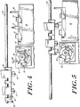
- FIG. 6 is a front, plan view of the service station of FIG. 2 showing the wiper arm at its final position of rotation;
- FIG. 7 is a front, plan view of the service station of FIG. 2 showing the printhead carriage engaging and rotating the wiper arm back to its initial position;
- FIG. 8 is a front, plan view of the service station of FIG. 2 showing the color pen of the printhead carriage in contact with the wiper, with the positions of the printhead carriage necessary to achieve the wiping action shown in phantom;
- FIG. 9 is a front, plan view of the service station of FIG. 2 showing the black pen of the printhead carriage in contact with the wiper, with the positions of the printhead carriage necessary to achieve the wiping action shown in phantom.
- FIG. 10 is a front, plan view of the service station of FIG. 2 showing the printhead carriage in a capped position and the wiper mechanism in a neutral position;
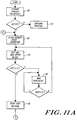
- FIG. 11A is a flow chart of the first two phases of the rehydration scrubbing cycle of the present invention;
- FIG. 11B is a flow chart of the third phase of the rehydration scrubbing cycle of FIG. 11A.
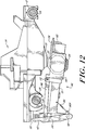
- FIG. 12 is a side view of a second embodiment of the wiper of this invention illustrating its relationship to the printhead carriage and the printhead;
- FIG. 13 is an isometric view of the wiper of FIG. 12;
- FIG. 14 is a perspective view of the cam carried by the printhead carriage of FIG. 12;
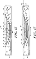
- FIG. 15 is a bottom, plan view of the cam of FIG. 14;
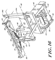
- FIG. 16 is a partial, prospective view of the wiper embodiment of FIG. 12 illustrating the relationship of the wiper to the cam as the printhead carriage approaches the service area;
- FIG. 17 is a bottom, plan view of the cam of FIG. 14 illustrating the path of the cam over the wiper mechanism to facilitate wiping of the printheads;
- FIG. 18 is a rear, plan view of the wiper embodiment of FIG. 12 illustrating the engagement of the cam and wiper mechanism to facilitate wiping of the printheads;
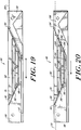
- FIG. 19 is a bottom, plan view of the cam of FIG. 14 illustrating the path of the cam over the wiper mechanism to facilitate rotation of the wiper blades; and
- FIG. 20 is a bottom, plan view of the cam of FIG. 14 illustrating the path of the cam over the wiper mechanism as the printhead carriage exits from the service area.
- With reference now to the drawings, and more particularly to FIG. 1 thereof, a typical ink-
jet printer 10 will be described with which the wiper of this invention may be used. Ink-jet printer 10, as shown in the drawings, is of the type in which printing is done in a substantially horizontal plane. However, it is to be understood that the wiper of this invention is shown used in conjunction with this type of printer for purposes of illustration only and that the wiper of this invention can be used with other types of ink-jet printers in which printing is not done in a substantially horizontal plane and which have different configurations. - Ink-
jet printer 10 includes ahousing 12, aprinthead carriage 14, acarriage guide 16, acarriage rod 18,drive roller assembly 20, platen 22,paper supply 26, andservice station 36. Driveroller assembly 20 feeds paper, or another print medium, supplied to it bypaper supply 26 to a printing zone disposed betweenprint head carriage 14 and platen 22 in a manner well known to those skilled in the art.Printhead carriage 14 travels back and forth oncarriage rod 18 and carriage guide 16 through the printing zone.Printhead carriage 14 is moved bi-directionally typically by means of abelt 19 connected to acarriage motor 27.Printhead carriage 14 includesprint cartridges electrical interconnect strip 24 to amicroprocessor 29.Microprocessor 29 also controlscarriage motor 27. Acontrol panel 28 is electrically associated withmicroprocessor 29 for selection of various options relating to the printing operation. Such control operations, provided by presently available microprocessors, are well known in the prior art and form no part of this invention. -
Print cartridges printhead carriage 14 bycarriage chutes Cartridges printhead Printheads printhead 31 is a color printhead which employs three sets of nozzles, each of which set expels a different primitive color, whileprinthead 33 utilizes only black ink. However, it is to be understood thatprintheads printhead 33 could use colored inks andprinthead 31 could use only black ink. Furthermore, any number of different colored inks could be used by any of the printheads, as desired. Typically, printheads 31 and 33 are thermal ink-jet printheads. However,printer 10 could operate with other ink-jet printheads, if the carriage interfaces are compatible, or with other carriage configurations. Furthermore, reconfiguration ofcartridges -
Printheads nozzle plate Nozzle plate 37 ofcolor printhead 31 contains three separate sets of plural nozzles, one for each color printed by the printhead. Ink is stored in reservoirs (not shown) withincartridges Printhead cartridges printheads - An assembled
service station 36 which includes the wiper of this invention is depicted in FIG. 2.Service station 36 is a region at one end of the bi-directional movement ofcarriage 14.Service station 36 includes a wiper mechanism, designated generally as 65. In theexemplary printer 10 with which this invention is being described,service station 36 also may include a sled 38, asled support 40 and a spittoon 41. However, the sled 38 forms no part of this invention and is not required for its operation. Typically,wiper mechanism 65 is disposed inservice station 36 on a side of sled 38 facing the center ofprinter 10 so thatprintheads mechanism 65 and so thatprintheads - Bosses 44 disposed on the sides of sled 38 rest on
ramps 46 ofsled support 40. Sled 38 is moveable alongramps 46 ofsled support 40 from left to right and right to left as shown in FIG. 2. Bosses 44 ride up along associatedramps 46 as the sled moves from left to right as shown in FIG. 2, from alower portion 48 to anupper portion 50, and visa versa. As sled 38 is in its most left-hand position, as shown in FIG. 2, bosses 44 reside inlower portion 48, while when sled 38 is in its most right-hand position (not shown), bosses 44 reside inupper portion 50 oframp 46. Sled 38 includes an upwardly extendingprojection 52 which is engaged by a surface ofcarriage 14, typically afront tab 54, as it moves over sled 38. Asfront tab 54strikes projection 52, caps 51 and 53 on sled 38 are automatically aligned withprintheads carriage 14 causes sled 38 to rise upwardly onramps 46 and causescaps orifice plates printheads ramps 46,projection 57 enters into a taperedslot 58intermediate printheads carriage 14 subsequently leavesservice station 36,projection 57 ensures that the sled 38 is returned to its inactive, lower position as shown in FIG. 2, in which bosses 44 reside inlower portion 48 oframp 46.Projection 57 drops out ofslot 58 as sled 38 is lowered to its inactive position. The purpose of the ramped sled motion is to prevent wear oncaps - Spittoon 41 is an open chamber which may be integrally formed with
sled support 40, as indicated in Fig. 2. Spittoon 41 retains ink ejected or spit fromprintheads - The wiper mechanism of this invention comprises at least the same number of blades as there are printheads. In the exemplary embodiment described herein, there are two wiping blades, one for each
printhead printhead carriage 14 dragging each printhead across its associated wiper blade while the blade is stationary. Thereafter, the blade is indexed for cleaning thereof and for bringing a fresh blade surface into wiping contact with a printhead. Ink may be expelled fromprintheads - A first embodiment of a wiper mechanism embodying this invention will now be described with particular reference to FIGS. 2-12. As shown in FIG 3,
wiper mechanism 65 compriseswiper 60, having at least twoblades arm 66,leaf spring 67,central shaft 68,pawl wheel 69,base 73, andhousing 70. - In the
printer 10 of the first illustrative embodiment of this invention,color printhead 31 is offset onprinthead carriage 14 with respect toblack printhead 33, so thatprinthead 31 is spaced farther from the paper and closer to the front ofprinter 10 than isprinthead 33. The typical orifice plate to paper spacing forprinthead 31 is 85/1000ths of an inch while the typical orifice plate to paper spacing forprinthead 33 is 52/1000ths of an inch. The positioning ofprintheads wiper 60 allows each printhead to be cleaned by a designated wiper blade, as explained hereinafter, and avoids cross-contamination or mixing of color and black ink on the printhead surfaces. -
Wiper 60 has a generally cylindrically shaped body with a central bore through whichshaft 68 passes.Wiper 60 includesblades shaft 68.Blades Blade 61 has a slightly greater length thanblade 63. Typically the difference between the lengths ofblades printhead 31 and that forprinthead 33. In the typical example provided herein, this difference is about 33/1000ths inch. When properly indexed, as explained hereinafter, the longer of the two blades,blade 61, is used to wipecolor printhead 31, which is recessed slightly, while the shorter blade,blade 63, is used to cleanblack printhead 33. - In the preferred embodiment,
shaft 68 has axial length of approximately 13 mm.Blades shaft 68 so that there is an overlap of approximately 1 mm. - In an alternate embodiment,
blades wiper 60 may be axially aligned alongshaft 68 providedprintheads wiper 60. -
Wiper 60 is preferably formed of a resilient material such as a synthetic rubber or the like, so that as a printhead passes over its corresponding wiper blade, the blade flexes to accommodate the irregular surface of the printhead and then returns to its original configuration without substantial deformation. A material suitable for use aswiper 60 is Ethylene Propylene Diene Monomer (EPDM) or nitrile rubber. A horizontal oscillating motion of a printhead over its respective wiper blade provides a firm aggressive wiping action along the distal tip of the blade which is preferred for satisfactory removal of dust, ink or other contaminants from the printhead. In the preferred embodiment,wiper 60 has four blades, oriented radially in an alternating pattern.Blades 61 and 61A wipeprinthead 31 andblades 63 and 63A wipeprinthead 33. Typically, the angular spacing betweenblades blades 63 and 61A andblades 61 and 63A is 60°. However, other numbers of blades and other spacings may be used, as desired. - The central bore of
wiper 60 is disposed aboutcentral shaft 68.Shaft 68 preferably has a rectangular cross-sectional configuration in the vicinity ofwiper 60 to provide a secure interlock betweenshaft 68 andwiper 60.Shaft 68 is rounded at its ends where it is journaled in cooperatively formed slots inhousing 70 andbase 73.Shaft 68 is coupled topawl wheel 69 which comprises acircular disk 69 having a plurality of inclined teeth, 69A and 69B, extending perpendicularly from each surface thereof.Pawl wheel 69 is movably coupled to ratchet 62.Ratchet 62 is comprised of a circular disk having a plurality ofinclined teeth 62A, similar to those ofpawl wheel 69, extending perpendicularly from one surface thereof.Ratchet 62 is disposed aboutshaft 68. The adjacent surfaces ofpawl wheel 69 and ratchet 62 which contain the inclined teeth, are engage in a complimentary mating manner.Leaf spring 67 is secured tobase 73 and biases pawlwheel 69 and ratchet 62 together in an interlocking relationship so thatwheel 69 and ratchet 62 rotate together in one direction, e.g. a clockwise direction.Wheel 69 is coupled towiper 60 viashaft 68 and produces rotation ofwiper 60 as it rotates.Wheel 69 andwiper 60 are prevented from rotating in a second direction, e.g., a counter clockwise direction, by inclined teeth 69B which engageleaf spring 67 to provide a ratcheting effect in a manner well known to those skilled in the art.Leaf spring 67 flexes in a direction parallel to the axis ofshaft 68 to permit movement ofratchet 62 in a direction opposite of the one direction with respect to ratchet 62, i.e., in a clockwise or counterclockwise direction. -
Arm 66, which is preferably comprised of a stiff, but resilient material such as plastic, is mounted to ratchet 62. Whenarm 66 is displaced, preferably with a rightward moving force applied to its distal end,inclined teeth 62A ofratchet 62 engageinclined teeth 69A ofpawl wheel 69 causing a rotation ofshaft 68 andwiper 60 in a clockwise direction. Asshaft 68 rotates,blades wiper 60 are rotated or indexed. When a leftward moving force is applied to the distal tip ofarm 66, leaf spring 77 flexes to allowratchet 62 to move in a counterclockwise direction over the surface ofpawl wheel 69 allowingarm 66 to return to its initial position. Simultaneously, one of the inclined teeth 69B engagesleaf spring 67 preventingpawl wheel 69 andshaft 68 from rotating, maintainingwiper 60 in its present status. In this manner,wiper blades wiper mechanism 65. -
Leaf spring 67 and cleaningapparatus 64 are secured towiper base 73.Shaft 68 is movably secured tobase 73 so thatratchet 62 andpawl wheel 69 are disposed inleaf spring 67 whilewiper 60 is disposed within cleaningapparatus 64.Wiper housing 70 is secured tobase 73 in an interlocking manner.Wiper housing 70 andbase 73 collectively enclose all elements ofwiper mechanism 65 except for the distal end ofarm 66 and the blades ofwiper 60 which extend through an irregular shaped aperture in the top surface ofhousing 70. -
Cleaning apparatus 64 encloses the portion ofwiper 60 spaced from the area in which wiping of the printheads occur.Blades apparatus 64 after wiping of the printheads aswiper 60 is indexed. In a preferred embodiment, cleaningapparatus 64 comprises at least one and preferably a plurality ofscrapers 72 disposed in an arcuate orientation around the perimeter of thewiper 60 as defined by the tips ofblades scrapers 72 are disposed extending towardwiper 60 from the interior surface of an arcuate cavity surrounding that portion ofwiper 60 spaced from the area where the wiping function is performed.Scrapers 72 each comprise a bilevel rigidblade having edges 72A and 72B that may face inwardly towardshaft 68, as shown in Fig. 3.Edge 72A rides along a portion of eachblade 61 and 61A, that passes thereover to perform the desired scraping action. Similarly, edge 72B rides along a portion of eachblade 63 and 63A that passes thereover.Edge 72A of each scraper is disposed closer to the interior surface of the arcuate cavity of cleaningapparatus 64, as shown in Fig. 3, to accommodateblades 61 and 61A which have a greater length.Scrapers 72 are rigidly mounted ontoapparatus 64 so that they do not move or flex asblades Scrapers 72 may each have an orientation generally parallel toblades shaft 68 or may have a non-radial alignment. Any circumferential spacing ofscrapers 72 is acceptable, so long as the tips ofblades edges 72A and 72B, respectively, of thescraper 72 during rotation ofwiper 60.Scrapers 72 are preferrably spaced inwardly from the tips of blades andnd 63 towardshaft 68 so that edges 72A-B scrape along the lateral surfaces of the blades and flex while passing thereover. This flexing of the blade produces a "flicking" action, as the blade tips return to their original configuration which also helps propel contaminants off the blades.Scrapers 72 may be disposed around the entire perimeter of the cavity in cleaningapparatus 64 except for the area abovewiper housing 70. - When more than one
scraper 72 is provided, eachblade scrapers 72, the length thereof, as well as their orientation is not critical, so long as the desired scraping action is provided. - It will be obvious that for an embodiment of
wiper 60 havingblades shaft 68 as shown in Figs. 1-2, 4-10, eachscraper 72 of cleaningapparatus 64 may have a single edge which scrapes all wiper blades, instead of a bilevel edge scraper in which eachedge 72A and 72B scrapes only selected blades. - Ink and contaminants which are removed from
wiper 60 byscrapers 72 tend to move under the influence of gravity and as a result of the flicking action ofblades scrapers 72 and away fromedges 72A-B. The ink tends to carry solid contaminants with it. Thus,scrapers 72 are self-cleaning, and need only be cleaned when solid contaminants have built up to an undesirably high level. -
Wiper 60 and the blades thereof are indexed as follows. A tab at the base ofarm 66 contacts a surface inbase 73 to limit rotary movement ofarm 66 from an initial position left of vertical, eg. 30°, to final position right of vertical, eg. 30°. Whenarm 66 rotates through a displacement, eg. 60°, ratchet 62 andpawl wheel 69 rotate in unison becauseleaf spring 67 urges them together and insures that the perpendicular surfaces of tooth 62B is adjacent the perpendicular surface of tooth 69B.Central shaft 68, which is coupled topawl wheel 69, causes a corresponding 60° rotation ofwiper 60 and a 60° angular displacement ofblades arm 66 is urged to its initial position at 30° left of vertical. Asarm 66 rotates to its initial position, the inclined surface oftooth 62A rides along inclined surface of one ofteeth 69A causing ratchet 69 andpawl wheel 69 to separate in an axial direction against the force ofspring 67 untilteeth 69A moves circumferentially into the next adjacent cooperatively formed slot. This process is repeated untilarm 66 strikes a surface ofbase 73.Pawl wheel 69 is retained in its current position byleaf spring 67 which is disposed adjacent the vertical surface oftooth 69A thereby preventing rotation ofwheel 69,shaft 68 andwiper 60. In this manner, successive displacements ofarm 66 by alternating rightwardly and leftwardly moving force cause indexing or rotation ofwiper 60 so that theblades wiper 60, precise positioning ofblades - The rotation of
blade wiper 60 in a clockwise direction through cleaningapparatus 64 provides an automatic cleansing of the blade tips following wiping of the printheads to prevent recontamination of the printheads and to reduce the servicing requirements forwiper 60. - The interaction of
wiper 60 withprinthead carriage 14 to achieve wiping ofprintheads printhead carriage 14, which is preferably belt driven, advances alongcarriage rod 18 with a rightwardly motion towardsservice station 36. Sled 38 is disposed insled support 40 at the lower portion of 48 oframp 46.Wiper 60 is disposed withinwiper housing 70 so that the "dead zone", the 120°area separating blades blades Arm 66 is disposed 30° left of the vertical, resting againstwiper housing 70, as shown. It should be noted thatrear tab 55 andflapper 56 ofprinthead carriage 14 as well asarm 66 ofwiper mechanism 65 are offset behindprintheads wiper 60. - As
printhead carriage 14 continues in a rightwardly direction towardsservice station 36,flapper 56, which is pivotally mounted toprinthead carriage 14,contacts arm 66 and is pivoted from its initial vertical position to a position 45° left of vertical to allow passage ofarm 66 thereunder. Asprinthead carriage 14 continues rightwardly,rear tab 55 engagesarm 66 causing it to rotate in a continuous manner to aposition 30° right of the vertical, as shown sequentially in FIGS. 5 and 6. Rotation ofarm 66 causes a similar rotation ofblade 61 from 60° left of vertical to vertical, as shown in FIG. 5. Asprinthead carriage 14 continues rightwardly,arm 66, which isposition 30° right of vertical, flexes to allow passage ofrear tab 55 thereover, as shown in Fig. 6.Printhead carriage 14 then stops, and changes directions, moving leftwardly. Asprinthead carriage 14 continues leftwardly,rear tab 55 again engagesarm 66 causing it to rotate in a continuous manner from its current position, 30° right of vertical, to its initial position, 30° left of vertical. Asprinthead carriage 14 continues leftwardly,arm 66 again flexes to allow passage ofrear tab 55 andflapper 56 thereover, as shown in Fig. 7. -
Leaf spring 67 engagesteeth 63 ofpawl wheel 69 preventingwiper 60 from rotating back to its initial position and retainingblade 61 in a vertical position, projecting fromhousing 70. - With the distal tip of
arm 66 disposed to the right oftab 55 andflapper 56,printhead carriage 14 next moves rightwardly to bring thenozzle plate 37 ofcolor printhead 31 into contact with the distal tip ofblade 61.Printhead carriage 14 then moves back and forth in an oscillating manner, causingnozzle plate 37 to be repeatedly drawn back and forth across the distal tip ofblade 61, thereby wipingnozzle plate 37 clean of contaminants. The various positions assumed byprinthead carriage 14,printhead 31 andblade 61 are shown in phantom in FIG. 8. In a preferred embodiment,printhead 31 is oscillated back and forth acrossblade 61 approximately three times to achieve adequate wiping of the nozzle plate. The algorithm of computer instructions which enablesmicroprocessor 29 to driveprinthead carriage 14 in an oscillating manner is well within the scope of those reasonably skilled in the data processing art. Such an algorithm simply manipulates the position ofprinthead carriage 14 along the axisparallel carriage rod 18 to create an oscillating ofprinthead 31. - After
printhead carriage 14 has moved acrossblade 61 the desired number of times, the printhead carriage moves rightwardly alongcarriage rod 18 so thatrear tab 55 again engagesarm 66 ofwiper mechanism 65 causing a 60° rotation ofarm 66 and a corresponding rotation ofwiper 60, as explained previously.Blade 63, which was positioned 60° left of vertical during the wiping ofcolor printhead 31 is now disposed vertically. Theprinthead carriage 14 then changes direction, moving leftwardly so thatrear tab 55 again engagesarm 66 causing it to rotate in a continuous manner, as previously described, to its initial position at 30° left of vertical. - The wiping of
black printhead 33 byblade 63 is achieved in a similar manner as that previously described with regard toprinthead 31 andblade 61. With the distal tip ofarm 66 disposed to the right oftab 55 andflapper 56,printhead carriage 14 moves rightwardly untilnozzle plate 39 ofprinthead 33 is in contact with the distal tip ofblade 63.Blade 63 remains stationary whilenozzle plate 39 is moved back and forth in an oscillating manner over the tip ofblade 63, as previously described with regard to the wiping ofprinthead 31. The various positions which printheadcarriage 14,printhead 33 andblade 63 assume during this process are shown in phantom in FIG. 9. Preferably,printhead 33 is moved acrossblade 63 three times to achieve adequate removal of contaminants from thenozzle plate 39. - The same computer algorithm used to manipulate the position of
printhead carriage 14 during the wiping ofprinthead 31 may be used to oscillate the position ofprinthead carriage 14 during the wiping ofprinthead 33, as would be obvious to one reasonably skilled in the art. - The number of wiping passes required to adequately
clean printheads - Once
printhead 33 has moved acrossblade 63 the desired number of times,printhead carriage 14 moves rightwardly towardsservice station 36.Rear tab 55 engagesarm 66, again causing a rotation ofarm 66 and corresponding rotation ofwiper 60, as previously described. This rotation ofwiper 60causes blade 63 to be rotated from vertical to 60° right of vertical causing another "dead zone" ofwiper 60, between blades 61A and 63A, to be facing upward as shown in Fig. 10. Asprinthead carriage 14 travels into theservice station 36,front tab 54 engagesprojection 52 of sled 38 with a rightwardly force. Asprojection 52 is moved to the right, bosses 44 are drawn from thelower level 48 oframp 46 to theupper level 50 oframp 46, coming to rest at the top ofsled support 40. Simultaneously,projection 57 enters taperedslot 58 and caps 51 and 53 are pressed against the perimeter ofnozzle plates Printhead carriage 14 remains in theservice station 36 while inactive as shown in FIG. 11. - When printhead
carriage 14 subsequently leavesservice station 36, the leftwardly motion of the printhead carriage movesprojection 57, and thus sled 38 leftwardly.Projection 57 withdraws fromslot 58, as sled 38 returns to its inactive, lower position, in which bosses 44 reside in lower portion oframp 46. Asprinthead carriage 14 moves leftwardly,rear tab 55 engagesarm 66 causing it to rotate in a continuous manner to its initial position and 30° left of vertical, as previously described. Due to its resilient nature,arm 66 flexes to allow the passage ofrear tab 55 andflapper 56 thereover. Sincewiper 60 is positioned with a "dead zone",printheads wiper assembly 65 without contact.Printhead carriage 14 may then continues with its printing functions. - The wiping operations described above may be programmed to automatically occur at the beginning or end of each page, as desired. Such instructional routines may be encoded into firmware which controls the printer operations and is well within the scope of one reasonably skilled in the firmware development arts.
- For proper execution of the above described wiping
sequences wiper 60 must be initially disposed in the "dead zone" position. To insure thatwiper 60 is in the dead zone position upon initialization or reset ofprinter 10,printhead carriage 14 moves through a "homing" sequence. The homing sequence ensures thatwiper 60 is in the dead zone position prior to initialization of a wiping sequence, even ifprinter 10 was accidentally powered down during a previous wiping sequence. - The homing sequence occurs as follows. Upon power-up or resetting of
printer 10,printhead carriage 14 moves into the print zone to the left ofservice station 36. Asprinthead carriage 14 moves leftwardly,rear tab 55encounters arm 66 and rotates it to its initial position, 30° left of vertical, if not already in that position at the time of powering or resetting ofprinter 10. Once in the print zone,printhead carriage 14 reverses directions, moving rightwardly so thatflapper 56contacts arm 66 and pivots thereover. Asprinthead carriage 14 continues rightwardly,rear tab 55 engagesarm 66 and rotates it continuously from its initial position, 30° left of vertical to a vertical position.Printhead carriage 14 then reverses directions, moving leftwardly so thatflapper 56 engagesarm 66 and rotates it continuously from its vertical position back to its initial position at 30° left of vertical. This step of rotatingarm 66, viatab 55, from its initial position to vertical, and from vertical back to its initial position, viaflapper 56, is repeated six times by manipulating the position and direction ofprinthead carriage 14, accordingly. - Referring again to Fig. 3, inclined teeth 69B of
pawl wheel 69 are arranged serially in groups of five teeth separated by flat surfaces 69C. Whenarm 66 is rotated clockwise through a displacement of 30°, ratchet 62 andpawl wheel 69 move in unison, as previously described, causing a corresponding 30° angular displacement ofshaft 68 andwiper 60. Upon rotation ofarm 66 in a counterclockwise direction,leaf spring 67 ratchets one of teeth 69B preventing rotation ofshaft 68 andwiper 60, thereby maintaining the position ofwiper blades pawl wheel 69 is rotated counterclockwise so thatleaf spring 67 encounters flat surface 69C, no ratcheting ofwheel 69 occurs.Wiper 60, in this instance only, also rotates counterclockwise due to the inability ofleaf spring 67 to engage flat surface 69C. Subsequent pairs of positive and negative 30° angular displacements result in no net displacement ofwiper blade 60 from its current position.Shaft 68 andwiper 60 are coupled topawl wheel 69 so that whenleaf spring 67 encounters one of the two flat surfaces 69C the "dead zone" ofwiper 60 is facing vertically. - If upon initiation of the homing sequence,
leaf spring 67 is ratcheted against any tooth 69B other than the first of a five tooth series,pawl wheel 69 will be rotated clockwise over the remaining teeth 69B, and, uponleaf 67 encountering flat space 69C, will rotate in both a clockwise and counterclockwise direction for the remainder of the homing sequence. Onceleaf spring 67 encounteres space 69C, subsequent pairs of positive and negative 30° angular displacements ofarm 66 will result in no net displacement ofwiper 60. If the homing sequence is initiated whenleaf spring 67 is currently positioned at flat surface 69C,wiper 60 will rotate 30° clockwise, followed by a 30° counterclockwise rotation, for each of the six stages in the homing sequence. However, the total net angular displacement ofwiper 60 during the homing sequence will be 0°. In this manner, regardless of the position ofwiper 60 upon initializing or resettingprinter 10,rear tab 55 andflapper 56 are used to ensure, thatwiper 60 is disposed with the dead zone facing vertically, as required for proper wiping ofprintheads - The homing sequence described above may be programmed to automatically occur upon initialization of
printer 10 after power up or reset, as desired. Such instructional routines may be encoded into firmware which controls the printer operations and is well within the scope of one reaonsably skilled in the firmware development arts. - It may be appreciated from the above explanation that the present invention provides a wiping mechanism which allows a printhead carriage having both a color printhead and a black printhead to be freed of contaminants by a wiper mechanism which has a separate, self-cleaning blades for each printhead, to prevent recontamination of a printhead and to further prevent cross contamination between the different printheads.
- The length of the wiper blades depends on the application, and manufacturing tolerances. For most applications,
blades blades 61 and 61A are longer thanblades 63 and 63A, typically by a distance of approximately .033". - As previously mentioned, during the printing process, debris such as paper fibers and dust, as well as ink spray, accumulate on the nozzle plates of the printheads. This debris and ink can cause poor nozzle performance resulting in poor quality printing. In printers which contain color printheads, such as
printer 10 of the illustrative embodiment, the accumulation of ink oncolor printhead 31 may cause mixing of ink or color contamination. Thenozzle plate 37 ofprinthead 31 needs to be cleaned periodically to eliminate these contaminants. If the printhead is used in a high air flow or heated environment, the ink begins to dry and subsequent wiping of the nozzle plate with a dry wiper blade often is not sufficient to remove the contaminants from the nozzle plate. - According to another aspect of the present invention, the ink from a printhead itself is used to rehydrate the ink residue and contaminants adhered to the nozzle plate surface. Generally, the method of the present invention, referred to as a rehydrating scrub cycle, includes the steps of spitting ink from the printhead to be wiped onto a wiper blade. This ink may be spit either as the printhead is drawn across the blade tip at a slow speed prior to wiping, or as the printhead is actually being wiped. The printhead is drawn across the wet blade at various speeds to remove ink and other debris in the manner previously described. This aspect of the invention typically is used only when initiated by the operator when the print quality has been observed to fall below an acceptable level. It is not generally routinely initiated at the beginning or end of each page of print.
- The preferred rehydrating scrub cycle described below is for illustrative purposes only and is not meant to limit the scope of the present invention. While the rehydrating scrub cycle of the present invention utilizes the interaction of the printer operator, it will be obvious to those reasonably skilled in the art that this method may be actuated and executed under control of a computer or microprocessor at periodic intervals. The instructional routine necessary for such an automated execution is within the scope of those reasonably skilled in the art and will not be explained in detail here.
- Referring to FIG. 11A, a flow chart of the steps comprising the rehydrating scrub cycle of the present invention is illustrated. The operator of ink-
jet printer 10 visually checks the printer output for defects in the printing quality of the printheads, as indicated bystep 90 of FIG. 11A. If no print errors exist, normal operation ofprinter 10 continues, as indicated bystep 91. If the print quality degrades below an acceptable level, or if a visually detectable defect exists, the operator stops the current print operation, as indicated bystep 92. The stepping of the current operation or clearing of the printhead typically occurs by depressing a clear button oncontrol panel 28 ofprinter 10. Such control operations, provided by presently available microprocessors, are well-known in the prior art and form no part of this invention. - The initial phase of the rehydrating scrub cycle begins with
printhead 31 moving across the distal tip ofblade 61 at a slow rate, preferably 1 inch per second, afterblade 61 has been indexed into a vertical position, as previously described. As the tip ofblade 61 approaches the nozzles ofprinthead 31, the printhead spits ink ontoblade 61, as indicated bystep 94 of FIG. 11A, referred to as a "wetting" pass. The ink ejected fromprinterhead 31 moistens the distal tip ofblade 61 and further moistens any dried ink and encrusted contaminants onnozzle plate 37. Some wiping occurs in this wetting pass. Following the wetting pass,printhead 31 is again drawn acrossblade 61 at a slow speed, preferably 1 inch per second, referred to as a "wiping" pass, indicated bystep 96 of FIG. 11A. The wiping pass further loosens and removes any contaminants and rehydrated ink. - As indicated by the flow chart of FIG. 11A, the rehydrating scrub cycle of the present invention provides four wetting passes each followed by four wiping passes to ensure that
nozzle plate 37 is free of contaminants The wiping passes must occur before the ink ejected in the wetting passes begins to dry on the nozzle plate of the printhead and the wiper blade. It will be obvious to those reasonably skilled in the art that the number and sequence of wetting and wiping passes may be selected according to the ink used and the printing environment. More passes may be required for more viscous ink, for finer solid contaminants or for faster build up of contaminants. It will be further obvious to those reasonably skilled in the art how to programmicroprocessor 29 to achieve the desired type, number, sequence, of passes of theprinthead 31 overblade 61. - The above-described initial phase of the rehydrating scrub cycle is generally effective in removing encrusted contaminants from
nozzle plate 37. However, due to the spitting of ink fromcolor printhead 31, inadvertent mixing of colored ink on thenozzle plate 37 may occur. To eliminate the mixing of colored ink onnozzle plate 37, second and third phases of the rehydrating scrub cycle are executed. - In the second phase of the rehydrating scrub cycle,
printer 10 executes a test pattern in which each nozzle ofnozzle plate 37 prints a horizontal line to determine whether each nozzle is firing properly and to clear any mixing of ink which may have occured onnozzle plate 37. Next, a dense pattern of graphics in the form of bar graphs is printed to ensure that all nozzles for each color ofprinthead 31 are firing properly and to clear any mixing of ink which may have occurred onnozzle plate 37. Following the bar graph pattern, another print test pattern of horizontal lines for each nozzle is printed. This printing step of test patterns is indicated asstep 98 of FIG. 11A. The printer operator visually inspects the printed test patterns to determine whether a problem exists with any particular nozzle or set of nozzles ofprinthead 31. - In the third and final phase of the rehydrating scrub cycle, a sequence of ink spitting and wiping passes is performed. As indicated by
step 100 of FIG. 11B,printhead 31 spits ink ten times into spittoon 41. Next, four wiping passes are executed in which the printhead is drawn across the tip ofblade 61 at a higher speed, preferably 6 inches per second. The combined sequence of 10 spits followed by four wiping passes is executed four times to further ensure removal of excess ink fromnozzle plate 37 and allow the nozzles to spit out encrusted material which has been loosened during the previous phases of the rehydrating scrub cycle. The number and sequence of ink spitting and wiping passes of the third phase of the rehydrating scrub cycle, as well as the programming steps necessary to achieve the same, as an obvious design choice, similar with that of the initial phase. - It will be obvious to those reasonably skilled in the art that any number or sequence of wiping and wetting passes, spitting and printing may be chosen to achieve the desired result. The above-described cycle is illustrative only and is not meant to be limiting.
- Following the third phase of the rehydrating scrub cycle, the operator of
printer 10 examines the print quality for further defects, as indicated bystep 104 of FIG. 11B. If the defects have been removed, normal printing operation continues, as indicated bystep 105. If defects in print quality continue to exist, the rehydrating scrub cycle may be executed as many as three times. If a printing defect still exists, replacement of the printhead cartridge may be necessary, as indicated bystep 106 of FIG. 11B. - It will be obvious to those reasonably skilled in the art that the rehydrating scrub cycle described above may be utilized with
black printhead 33 in a manner similar to that utilized for freeingprinthead 31 of contaminants. Because there is no danger of ink mixing onblack printhead 33, fewer wiping and wetting passes may be required than the above described method. However, the steps of the rehydrating scrub cycle are substantially similar. - A second embodiment of the present invention, referred to generally as
wiper mechanism 140, will now be described with particular reference to FIGS. 12-20. This second embodiment is particularly desirable in printers which require a high air-flow environment, as more vigorous scrubbing can be produced to remove dried ink and ink can be spit onto the blades to rehydrate the ink for each wiping operation. A typical ink-jet printer 110 with which the wiper of the second embodiment of the present invention may be used is substantially similar toprinter 10 of the first embodiment of the present invention, except thatprinthead carriage 114 travels back and forth through the printing zone oncarriage rods printhead carriage 114 has been modified to receive thesecond carriage rod 119. Referring to FIG. 12, a side view ofprinthead carriage 114 is shown illustrating its relationship towiper mechanism 140.Printhead carriage 114 is slidably mounted oncarriage rods -
Printhead carriage 114 includes print cartridges 130 and 132. Print cartridge 130 includescolor printhead 131 withnozzle plate 137 which are similar in function and design to printhead 31 and itsnozzle plate 37 ofprinter 10 of the first embodiment. Similarly, print cartridge 130 includesblack printhead 133, which is similar in function and design toblack printhead 33 ofprinter 10 of the first embodiment. Unlikeprintheads printheads printhead carriage 114 and therefore have the same printhead to paper spacing. Otherwise, the means by which theprinthead carriage 114 is positioned and the operation of theprintheads printer 10 of the first embodiment. - A
cam 180 is secured to the rear ofprinthead carriage 114 to selectively engagewiper mechanism 140, depending on the position ofprinthead carriage 114, as explained hereinafter. - Referring to FIGS. 12 and 13,
wiper mechanism 140 is comprised ofwiper frame 150,first cam follower 142,second cam follower 144,lever 146,slider mechanism 148,axle 152,color blade 154,black blade 156,blade cleaners spring 166,bosses 168, anddisks 170. - As illustrated in FIG. 13,
wiper frame 150 is generally rectangular in shape with aframe arm 151 extending perpendicularly from one side thereof.Wiper frame 150 is pivotally coupled to the machine frame in the service station atpivot point 172 to permit pivoting aboutaxis 155. The distal end offrame arm 151 includes a pair of spaced downwardly facing legs 151D. Afirst cam follower 142 is disposed intermediate legs 151D and pivotally coupled at itsproximal end 142P to the lower ends of the legs 151D. A distal tip 142D is disposed at the opposite end ofcam follower 142. The extreme distal portion of tip 142D has a tapered shape to facilitate engagingcam 180, as explained hereinafter. Theproximal end 142P ofcam follower 142 has a tab tip which extends towardwiper frame 150, as illustrated in FIG. 13. The tab onproximal end 142P ofcam follower 142 is coupled toarm 151 ofwiper frame 150 by acoil spring 166 which biasesfirst cam follower 142 in a direction away fromwiper frame 150. AU-shaped stop 170 is attached to legs 151D ofarm 151 to limit pivoting ofcam follower 142 away fromarm 151. A downward force, applied to distal tip 142D ofcam follower 142 will causewiper frame 150 to pivot aboutaxis 155 atpivot point 172, as explained hereinafter. - A
second cam follower 144 includes a generally U-shaped body portion with upwardly facingarms 144A and 144B, as illustrated in FIG. 13. A pair ofbosses 168 project perpendicularly from the sides ofcam follower 144 near its base.Bosses 168 enablecam follower 144 to be pivotally mounted to the machine frame in the service station of printer 110.Arm 144A ofcam follower 144 includes a distal tip 144D which has a configuration of lateral surfaces adapted to interact withcam 180 ofprinthead carriage 114, as explained hereinafter. Arm 144B ofcam follower 144 has a pair of spaced legs. Alever 146 is disposed between the legs and is pivotally coupled thereto. - The second end of
lever 146 is pivotally coupled to aslider mechanism 148 which is in turn slidably mounted about one side ofwiper frame 150 in a sleeve-like manner.Slider 148 is coupled to a conventional ratchet mechanism 149 which converts the reciprocating motion ofslider 148 into a rotary motion for rotation of the wiper blades, as explained hereinafter. - An
axle 152, having a pair of octagonal-shaped disks at each end thereof, is rotatably mounted at each end inwiper frame 150. Awiper blade 154 is disposed intermediateoctagonal disks 172 at one end ofaxle 152, and an octagonal-shapedwiper blade 156 is disposed intermediateoctagonal disks 174 at the opposite end ofaxle 152.Disks 174 should have the same configuration asblades blade Blades Wiper blades exterior disk 174adjacent wiper 154 is coupled to ratchet mechanism 149 so thataxle 152 andblades slider 148 activates ratchet mechanism 149 in a conventional manner which is well understood by those skilled in the art. - A pair of blade cleaners, 158 and 160, preferably each comprised of an absorbent material, and having a slit in one side thereof is mounted to
wiper frame 150 bysupport members Blade wipers blades wiper blades blade cleaners wipers blades Wipers - It may be appreciated from the previous explanation that the
wiper mechanism 140 of the second embodiment of the present invention, when pivotally mounted to the service station of printer 110, provides contact betweenwiper blades printheads 131 and 132 respectively, depending upon the position ofprinthead carriage 114 in relation towiper mechanism 140.Blade 154 only wipes printhead 131 andblade 156 only wipes printhead 132 to prevent cross-contamination. - This engagement occurs as follows.
Cam 180, attached toprinthead carriage 114, has a plurality of camming surfaces separated by dividing walls. Asprinthead carriage 114 advances towards the service station of printer 110,first cam follower 142 engagescam 180. Asprinthead carriage 114 continues in its rightwardly motion, the distal tip 142D ofcam follower 142 rides up on the camming surfaces ofcam 180 which pushesfollower 142 downwardly and causes a pivoting ofwiper frame 150 aboutaxis 155. A corresponding but opposite upward displacement ofwiper blades cam 180 with a plurality of selectively contoured grooves which cause variations in vertical displacement ofcam follower 142 as the position ofcam 180 andprinthead carriage 114 change,wiper blades printheads printhead carriage 114 passes overwiper mechanism 140. Whenprinthead carriage 114 is reciprocated back and forth in an oscillating manner overwiper mechanism 140,wiper blades printheads color printhead 131 and theblack printhead 133 are wiped simultaneously. - As
printhead carriage 114 andcam 180 travel further in a rightwardly direction,cam 180 engagessecond cam follower 144 causing an indexing ofwiper blades wiper blades printhead carriage 114 continues into the service station area of printer 110,cam 180 disengagesfirst cam follower 142 and engagessecond cam follower 144.Cam 180 selectively deflects distal tip 144D ofsecond cam follower 144. The deflection of distal tip 144D causes pivotal rotation ofcam follower 144 aboutaxis 165. The rotary motion ofcam follower 144 is translated into a reciprocating motion bylever 146 which is pivotally coupled to bothcam follower 144 andslider 148.Slider 148 imparts the reciprocating motion to ratchet mechanism 149 which in turn rotatesaxle 152 andwiper blades wiper blades blade cleaners - Referring to FIGS. 14 and 15, a
preferred cam 180 contemplated for use with the second embodiment of the present invention is illustrated.Cam 180 has a flat, rectangular top surface from which a number of camming surfaces, ramps and grooves project downwardly.Cam 180 comprisestop surface 181, cam surfaces 182, 184 and 186,cam grooves walls - As illustrated in FIGS. 14 and 15, cam surfaces 182, 184, and 186 and
cam groove 198 lie in planes parallel totop surface 181.Ramps cam surface 186.Ramps cam groove 198. -
Walls cam surface 182.Cam groove 188 liesintermediate walls Cam groove 190 liesintermediate wall cam grooves Ramp 191 extends between cam surfaces 182 and 184 and liesadjacent wall 204.Wall 200 is terminated at one end by an oblique surface, designatedrelease surface 206. Similarly,walls -
Cam 180 is preferably comprised of a rigid material such as plastic or the like so that the cam will not deform when engaged bycam followers cam 180 moves over the cam followers. - A description of the engagement of
wiper 140 andcam 180 to facilitate wiping ofprintheads printhead carriage 114 advances rightwardly toward the service station of printer 110,cam 180 engagesfirst cam follower 142. The path ofcam 180 across distal tip 142D ofcam follower 142 is illustrated by dashedline 250 in FIG. 17. Asprinthead carriage 114 moves rightwardly,cam surface 182 moves over distal tip 142D. When the center ofcam surface 182 passes over distal tip 142D,printheads wiper blades blades nozzle plates 137 and 139, respectively, as explained hereinafter. Ascam 180 continues rightwardly, distal tip 142D contacts ramp 191 which displaces tip 142D downwardly causingwiper frame 150 to pivot aboutaxis 155 and displaceblades printheads cam 180 continues its rightward,movement cam surface 184 maintains the displacement ofcam follower 142 and maintainsblades nozzle plates 137 and 139 ofprintheads - As
cam 180 continues rightwardly, distal tip 142D reaches the edge ofcam surface 184 and pivots upward to its normal position causing a corresponding downward movement of wiper blades of 154 and 156 away fromprintheads -
Printhead carriage 114 then changes direction, now moving leftwardly. Ascam 180 continues to the left, tip 142D, which is spring biased away fromwiper 140, contacts ramp 192 and is deflected thereby. Tip 142D is increasingly deflected as it followsramp 192. Upon reaching the end oframp 192, tip 142Dfollow ramp 193 which maintain its deflection, ascam 180 continues leftward. Upon reaching the edge oframp 193, tip 142D pivots, because of its spring bias, intocam groove 188. - At this point,
printhead carriage 114 again reverses direction now moving rightwardly. Ascam 180 continues rightwardly, distal tip 142D, retained bywalls contacts cam groove 188 which causes a gradual downward displacement of tip 142D and a corresponding gradual, upward displacement ofblades surface 188A, at the center ofcam groove 188 reaches tip 142D, the displacement of tip 142D andblades blades nozzle plates 137 and 139, respectively as shown in FIG. 18. - As
printhead carriage 114 andcam 180 continue respectively rightwardly,nozzle plates 137 and 139 are drawn acrossblades printhead carriage 114 continues rightwardly, tip 142D is gradually displaced upwardly, causingblades printhead carriage 114 andcam 180 changes directions, moving leftwardly so thatcam groove 188 displaces tip 142D downwardly a second time causing a second short scrub stroke of the printheads. - It will be obvious to those reasonably skilled in the art that once tip 142D is positioned within
cam groove 188 subsequent scrub stroke wipings ofprintheads printhead carriage 114 andcam 180, in an oscillating manner. In the preferred embodiment,cam 180 reverses direction three times causing four "scrub" strokes asnozzle plates 137 and 139 are dragged acrosswiper blades cam groove 188 is drawn across distal tip 142D at a rate of approximately three inches per second. However, both this value or the number of strokes should not be considered limiting in any manner. - Following the last scrub stroke,
cam 180 is moving leftwardly with distal tip 142D biased againstwall 202. Upon reaching the edge ofwall 202, atrelease point 208, tip 142D, because of its spring bias, pivots intocam groove 190, as indicated in FIG. 17. At this point,printhead carriage 114 again changes direction, now moving rightwardly. Asprinthead cam 180 continues rightwardly,cam groove 190 is drawn across distal tip 142D causing a gradual, downward, displacement thereof and a corresponding gradual, upward displacement ofblades cam groove 190, is drawn across distal tip 142D,cam follower 142 reaches a constant vertical displacement. At this point,blades nozzle plates 137 and 139, respectively. Asprinthead carriage 114 continues rightwardly,nozzle plates 137 and 139 are drawn acrossblades cam surface 190A. - As illustrated in FIG. 17,
surface 190A is considerably larger thansurface 188A allowing for greater contact between the wiper blades and the nozzle plates. The resulting wiping action is referred to as a "wiping" stroke. In the preferred embodiment, thecam groove 190 is drawn across distal tip 142D at a rate of approximately twelve inches per second, causingnozzle plates 137 and 139 to be drawn acrosswiper blades printhead carriage 114 andcam 180 are drawn acrosswiper mechanism 140 may vary according to the environment and the viscosity of the ink used in ink jet printer 110. The above rate used in the preferred embodiment should not be interpreted as limiting in any manner. - As
cam 180 continues rightwardly, distal tip 142D reaches the edge ofcam groove 190 and is displaced upwardly therefrom. Tip 142D is biased againstramp 192 which it follows until reaching its neutral position. Asprinthead carriage 114 andcam 180 continue rightwardly,surface 186 moves above distal tip 142D without contact. - As
printhead carriage 114 continues rightwardly,second cam follower 144 ofwiper mechanism 140 engagescam 180. Ascam 180 moves farther rightwardly,second cam follower 144 is received withincam groove 198 which moves above distal tip 144D in a noncontacting manner. Ascam 180 continues rightwardly distal tip 144D contacts ramp 194 and is increasingly deflected thereby, following the path indicated by dashedline 260 of FIG. 19. The deflection of distal tip 144D causes pivotal rotation ofcam follower 144 aboutaxis 165. The rotary motion ofcam follower 144 is translated into a reciprocating motion bylever 146 which is pivotally coupled to bothcam follower 144 andslider 148.Slider 148 imparts the reciprocating motion to ratchet mechanism 149 which in turn rotatesaxle 152 andwiper blades wiper blades slits blade cleaners - As
printhead carriage 114 continues rightwardly distal tip 144D contacts ramp 197 and remains in a deflected position, as indicated in FIG. 19 asprinthead carriage 114 comes to rest in the service station area.Printhead carriage 114 is then in a position, as previously described with regard to the first embodiment of the present invention, in whichprintheads printhead carriage 114 leaves the service area moving leftwardly, causing distal tip 144D ofsecond cam follower 144 to disengage fromcam 180, following the same path as that of its initial engagement except in reverse, as indicated in FIG. 19. - As
printhead carriage 114 andcam 180 continue leftwardly,cam 180 re-engages distal tip 142D offirst cam follower 142, as shown by dashedline 270 in FIG. 20.Cam surface 186 moves abovedistal tip 142 in a noncontacting manner. Ascam 180 continues leftward, tip 142D is deflected byramp 192. Tip 142D is deflected byramp 192 which it follows until reachingramp 193. Ascam 180 continues leftwardly, tip 142D followsramp 193 until reachingrelease point 206. Atrelease point 206, tip 142D pivots againstwall 202 which it follows briefly until reachingrelease point 208. Atrelease point 208, tip 142D pivots againstwall 204 which it follows briefly until reachingrelease point 210. Atrelease point 210, tip 142D is biased to its normal position. Ascam 180 continues leftward,surface 182 andcam groove 198 move over distal tip 142D, without further contact asprinthead carriage 114 moves into the print zone, as indicated in FIG. 20. - It may be appreciated from the above description that as
printhead carriage 114 exits from the service station area, the contact betweencam 180 and the cam followers does not cause further pivoting ofwiper frame 150 or rotation ofblades printheads - The interaction of
cam 180 andwiper mechanism 140 as described above enablesprintheads printhead carriage 114 andcam 180. In the preferred embodiment,printhead carriage 114 is oscillated in a back and forth manner to provide four short "scrub" strokes followed by one long "wipe" stroke, and further followed by a rotation ofwiper blades printheads printhead carriage 114 may be manipulated to achieve other sequences or types of wiping action, the instructional algorithms used to manipulate theprinthead carriage 114 for such actions being obvious to those reasonably skilled in the art. Also, it will also be obvious to those reasonably skilled in the art that the surfaces ofcam 180 may be modified to achieve different deflections and displacements ofcam followers wiper blades - The wiper of this invention permits the removal of dust, ink and other contaminants from color and black printheads, and prevents their buildup during use. Cross contamination of the printheads is prevented, and automatic self-cleaning is provided.
- In view of the above description, it is likely that modifications and improvements will occur to those skilled in the art which are within the scope of this invention. The above description is intended to be exemplary only, the scope of the invention being defined by the following claims and their equivalents.
Claims (22)
- Apparatus for cleaning first and second printheads disposed on a printhead carriage (14) in an ink-jet printer comprising:
a first wiper blade (61, 154) for wiping a first printhead (31);
a second wiper blade (63, 158) for wiping a second printhead (33);
means (65) for selectively bringing said first wiper blade (61) into wiping contact only with said first printhead (31), and for selectively bringing said second wiper blade (63) into wiping contact only with said second printhead (63); and
means (14, 27, 29, 19, 18) for producing relative wiping motion between said first printhead (31) and said first wiper blade (61) and said second printhead (33) and said second wiper blade (63). - Apparatus as recited in claim 1 further comprising means (55) for actuating said bringing means in response to motion of the printhead carriage (14).
- Apparatus as recited in claim 1 wherein the printhead carriage (14) travels bidirectionally through a printing zone in which printing is produced by the first and second printheads (31, 33) on a print medium and wherein said first and second wiper blades (61, 63) are disposed in a service station area (36) disposed outside of said printing zone adjacent one end of the printing zone.
- Apparatus as recited in claim 3 wherein said bringing means (65) is actuated by movement of the printhead carriage (14) into said service station area (36).
- Apparatus as recited in claim 4 wherein surfaces (55, 54) on the printhead carriage (14) mechanically interact with at least one arm (66) associated with said bringing means (65) to cause said bringing means (65) to selectively bring said first wiper blade (61) into wiping contact only with said first printhead (31) and to selectively bring said second wiper blade (63) into wiping contact only with said second printhead (33).
- Apparatus as recited in claim 5 wherein said producing means (14, 18, 19, 27, 29) comprises means (19, 27, 29) for moving the printhead carriage (14).
- Apparatus as recited in claim 6 wherein said moving means comprises:
a motor (27);
means (19) coupling said motor to the printhead carriage;
computer means (29) for controlling said motor (27) and said coupling means (19); and
means (18) for guiding movement of the printhead carriage (14) in said service station area (36). - Apparatus as recited in claim 1 further comprising means (64) for removing contaminants from said first and said second wiper blades (61, 63).
- Apparatus as recited in claim 8 wherein said removing means comprises at least one scraper (72).
- Apparatus as recited in claim 1 wherein said first wiper blade (61) and said second wiper blade (63) extend from a wiper body (60) rotable about a central axis.
- Apparatus as recited in claim 10 wherein said first and second wiper blades (61, 63) extend generally radially outwardly from said central axis and have distal tips which are spaced from one another.
- Apparatus as recited in claim 10 wherein said bringing means (65) comprises means (62, 66, 67, 68, 69) for rotating said wiper body (60) about said central axis of rotation.
- Apparatus as recited in claim 12 wherein said rotating means (62, 66, 67, 68, 69) is responsive to movement of the printhead carriage (14).
- Apparatus as recited in claim 13 wherein said rotating means (62, 66, 67, 68, 69) comprises a lever arm (66) actuated by movement of the printhead carriage (14).
- Apparatus as recited in claim 14 wherein said lever arm (66) is selectively actuated by movement of the printhead carriage (14) in only one direction.
- Apparatus as described in claim 11 wherein said first wiper blade (61) and said second wiper blade (63) each have a length extending from its distal tip to said axis of rotation, wherein the length of said first wiper blade (61) is different from the length of said second wiper blade (63), and wherein said first printhead (31) has a printhead-to-paper spacing different from the printhead-to-paper spacing of the second printhead (33).
- Apparatus as recited in claim 1 further comprising a third wiper blade (61A) for cleaning the first printhead (31) and a fourth wiper blade (63A) for cleaning the second printhead (33).
- Apparatus as recited in claim 1 wherein said first (154) and said second (156) wiper blades each have a polygonal shape and a central axis of rotation passing through a center thereof.
- Apparatus as recited in claim 18 wherein said bringing means comprises:
a cam (180) coupled to the printhead carriage;
a pivotally mounted frame (150) to which said first and second blades (154, 158) are secured; and
a cam follower (142) responsive to movement of said cam (180) for pivoting said frame (150) about an axis of rotation. - Apparatus as recited in claim 19 in which said first and second wiper blades (154, 156) are selectively pivoted into contact with said first printhead (131) and said second printhead (133), respectively, in response to said cam (180).
- Apparatus as recited in claim 19 further comprising indexing means (144, 146, 148, 152, 174) for rotating said first and said second wiper blades (154, 156) about said central axis of rotation.
- Apparatus as recited in claim 21 comprising first (162) and second (164) absorbent members disposed in frictional contact with said first (154) and second (156) wiper blades, respectively, for absorbing contaminants as said wiper blades are rotated.
Applications Claiming Priority (2)
| Application Number | Priority Date | Filing Date | Title |
|---|---|---|---|
| US07/549,583 US5103244A (en) | 1990-07-05 | 1990-07-05 | Method and apparatus for cleaning ink-jet printheads |
| US549583 | 1990-07-05 |
Publications (3)
| Publication Number | Publication Date |
|---|---|
| EP0465260A2 true EP0465260A2 (en) | 1992-01-08 |
| EP0465260A3 EP0465260A3 (en) | 1992-02-26 |
| EP0465260B1 EP0465260B1 (en) | 1995-10-04 |
Family
ID=24193588
Family Applications (1)
| Application Number | Title | Priority Date | Filing Date |
|---|---|---|---|
| EP91306107A Expired - Lifetime EP0465260B1 (en) | 1990-07-05 | 1991-07-04 | Method and apparatus for cleaning ink-jet orifice plate |
Country Status (4)
| Country | Link |
|---|---|
| US (1) | US5103244A (en) |
| EP (1) | EP0465260B1 (en) |
| JP (1) | JP3290448B2 (en) |
| DE (1) | DE69113534T2 (en) |
Cited By (30)
| Publication number | Priority date | Publication date | Assignee | Title |
|---|---|---|---|---|
| EP0526061A2 (en) * | 1991-07-30 | 1993-02-03 | Hewlett-Packard Company | Service station for ink-jet printer |
| EP0581553A2 (en) * | 1992-07-28 | 1994-02-02 | Canon Kabushiki Kaisha | Wiping mechanism for ink jet recording head and recording apparatus using same |
| EP0604067A2 (en) * | 1992-12-21 | 1994-06-29 | Hewlett-Packard Company | Printhead servicing apparatus |
| EP0630755A2 (en) * | 1993-06-21 | 1994-12-28 | Canon Kabushiki Kaisha | Ink jet recording apparatus having discharge recovery means |
| EP0653306A2 (en) * | 1993-11-11 | 1995-05-17 | OLIVETTI-CANON INDUSTRIALE S.p.A. | Service station for an ink jet printer |
| EP0676290A2 (en) * | 1994-04-08 | 1995-10-11 | Hewlett-Packard Company | Inkjet printer with variable wiping capabilities for multiple printheads |
| EP0678389A1 (en) * | 1994-04-21 | 1995-10-25 | Fujitsu Limited | Method of and apparatus for cleaning ink jet head |
| EP0705700A1 (en) * | 1994-09-30 | 1996-04-10 | Hewlett-Packard Company | Multiple chimneys for inkjet printer |
| EP0709204A1 (en) * | 1994-10-28 | 1996-05-01 | Hewlett-Packard Company | Wet wiping system for inkjet printheads |
| EP0714778A1 (en) * | 1994-05-17 | 1996-06-05 | Seiko Epson Corporation | Ink jet recorder and method of cleaning recording head |
| EP0732211A1 (en) * | 1995-03-06 | 1996-09-18 | Hewlett-Packard Company | Independent service stations for multiple printheads in inkjet printers |
| US5614930A (en) * | 1994-03-25 | 1997-03-25 | Hewlett-Packard Company | Orthogonal rotary wiping system for inkjet printheads |
| US5680162A (en) * | 1994-09-30 | 1997-10-21 | Hewlett-Packard Company | Multiple chimneys for ink jet printer |
| EP0858895A2 (en) * | 1997-02-18 | 1998-08-19 | Canon Kabushiki Kaisha | Liquid discharge apparatus |
| EP0913263A1 (en) * | 1997-10-29 | 1999-05-06 | Hewlett-Packard Company | Hide-away wiper cleaner for inkjet printheads |
| EP0913262A1 (en) * | 1997-10-31 | 1999-05-06 | Hewlett-Packard Company | Narrow and wide wiper blade cleaning system for ink jet printheads |
| US5905514A (en) * | 1996-11-13 | 1999-05-18 | Hewlett-Packard Company | Servicing system for an inkjet printhead |
| US5907335A (en) * | 1996-11-13 | 1999-05-25 | Hewlett-Packard Company | Wet wiping printhead cleaning system using a non-contact technique for applying a printhead treatment fluid |
| US5914734A (en) * | 1996-11-13 | 1999-06-22 | Hewlett-Packard Company | Printhead servicing system and method using a moveable wiper between a fluid source and a printhead |
| US5969731A (en) * | 1996-11-13 | 1999-10-19 | Hewlett-Packard Company | Print head servicing system and method employing a solid liquefiable substance |
| EP1010535A2 (en) * | 1998-12-15 | 2000-06-21 | Canon Kabushiki Kaisha | Ink jet printing apparatus |
| GB2357735A (en) * | 2000-01-31 | 2001-07-04 | Hewlett Packard Co | Flipping wiper scraper service station for cleaning a wiper blade of an inkjet printhead system |
| EP1195251A1 (en) * | 2000-10-04 | 2002-04-10 | Canon Kabushiki Kaisha | Head recovery device, head recovery method and ink jet recording apparatus |
| US6409303B1 (en) * | 2000-03-31 | 2002-06-25 | Hewlett-Packard Company | Two-stage scraper system for inkjet wipers |
| EP1310367A1 (en) * | 2001-11-08 | 2003-05-14 | Agfa-Gevaert | Service station for inkjet printing system |
| GB2389079A (en) * | 2000-01-31 | 2003-12-03 | Hewlett Packard Co | Flipping wiper scraper system for inkjet printheads |
| EP1464498A2 (en) * | 2003-03-25 | 2004-10-06 | Toshiba Tec Kabushiki Kaisha | An ink jet recording apparatus having maintenance means for cleaning an ink jet recording head |
| CN100999157B (en) * | 2006-01-12 | 2010-12-15 | 精工爱普生株式会社 | Wiper device and liquid ejection apparatus |
| WO2011067339A1 (en) * | 2009-12-02 | 2011-06-09 | Prometal Rct Gmbh | Print head cleaning device |
| DE19608487B4 (en) * | 1995-03-06 | 2014-05-15 | Hewlett-Packard Development Co., L.P. | Inkjet printer and method of servicing an inkjet printer |
Families Citing this family (123)
| Publication number | Priority date | Publication date | Assignee | Title |
|---|---|---|---|---|
| ATE164552T1 (en) * | 1991-01-11 | 1998-04-15 | Canon Kk | INKJET RECORDING DEVICE |
| JP2901361B2 (en) * | 1991-02-28 | 1999-06-07 | キヤノン株式会社 | Ink jet recording device |
| JP3058200B2 (en) * | 1991-06-24 | 2000-07-04 | セイコーエプソン株式会社 | Ink jet recording device |
| DE69214007T2 (en) * | 1991-05-15 | 1997-02-06 | Seiko Epson Corp | Ink jet type recording device and cleaning method of the recording head |
| ATE181882T1 (en) * | 1992-03-09 | 1999-07-15 | Canon Kk | MULTIPLE RECORDING APPARATUS USING A MONOCHROME PRINTER |
| JP3110151B2 (en) * | 1992-04-14 | 2000-11-20 | キヤノン株式会社 | Ink jet recording device |
| JP2832776B2 (en) * | 1992-06-12 | 1998-12-09 | キヤノン株式会社 | Ink jet recording device |
| US5621441A (en) * | 1992-09-21 | 1997-04-15 | Hewlett-Packard Company | Service station for inkjet printer having reduced noise, increased ease of assembly and variable wiping capability |
| US5434605A (en) * | 1992-09-21 | 1995-07-18 | Hewlett-Packard Company | Automatic failure recovery method and system for ink-jet printheads |
| US5563638A (en) * | 1992-09-21 | 1996-10-08 | Hewlett-Packard Company | Ink-jet printhead capping and wiping method and apparatus |
| US5396277A (en) * | 1992-09-25 | 1995-03-07 | Hewlett-Packard Company | Synchronized carriage and wiper motion method and apparatus for ink-jet printers |
| EP0590853B1 (en) * | 1992-09-30 | 2000-11-08 | Hewlett-Packard Company | Ink-jet printer color palette selection method and system |
| JP3535885B2 (en) * | 1992-12-16 | 2004-06-07 | セイコーエプソン株式会社 | Ink jet recording device |
| US5394178A (en) * | 1992-12-21 | 1995-02-28 | Hewlett-Packard Company | Printhead servicing apparatus with pivotal servicing lever |
| EP0604938B1 (en) * | 1992-12-28 | 1997-05-07 | Canon Kabushiki Kaisha | Ink jet apparatus and recovery method therefor |
| JP3241844B2 (en) * | 1993-01-25 | 2001-12-25 | キヤノン株式会社 | Recording device and recording method |
| JPH06340081A (en) * | 1993-04-19 | 1994-12-13 | Xerox Corp | Printing head maintenance device for full-width ink jet printer |
| US5455608A (en) * | 1993-04-30 | 1995-10-03 | Hewlett-Packard Company | Pen start up algorithm for black and color thermal ink-jet pens |
| US5602573A (en) * | 1993-04-30 | 1997-02-11 | Hewlett-Packard Company | Service station for inkjet printer having wipers with concave wiping edges |
| US5585826A (en) * | 1993-04-30 | 1996-12-17 | Hewlett-Packard Company | Service station for simultaneous capping/wiping of multiple inkjet cartridges having different inks |
| US5424768A (en) * | 1993-06-21 | 1995-06-13 | Xerox Corporation | Zero-volume maintenance cap for an ink jet printhead |
| US5500660A (en) * | 1993-06-24 | 1996-03-19 | Hewlett-Packard Company | Wiper for inkjet printhead nozzle member |
| US5534897A (en) * | 1993-07-01 | 1996-07-09 | Xerox Corporation | Ink jet maintenance subsystem |
| US5489927A (en) * | 1993-08-30 | 1996-02-06 | Hewlett-Packard Company | Wiper for ink jet printers |
| US6206497B1 (en) * | 1993-09-10 | 2001-03-27 | Canon Kabushiki Kaisha | Liquid ejecting apparatus with variable wiping of a liquid ejection head |
| US5563637A (en) * | 1993-10-26 | 1996-10-08 | Lexmark International, Inc. | Maintenance station for ink jet printhead |
| US5612722A (en) * | 1993-10-26 | 1997-03-18 | Lexmark International, Inc. | Ink jet printhead wiper having side surfaces intersecting a top surface at acute angles to form wiping edges and a slat centered in a bottom surface |
| JPH07137270A (en) * | 1993-11-16 | 1995-05-30 | Canon Inc | Ink jet recorder |
| DE4443923B4 (en) * | 1993-12-10 | 2008-08-07 | Seiko Epson Corp. | inkjet |
| JP3088615B2 (en) * | 1994-01-25 | 2000-09-18 | キヤノン株式会社 | Discharged ink processing method, recovery device and ink ejection device for implementing the method |
| JPH07246708A (en) * | 1994-03-10 | 1995-09-26 | Canon Inc | Ink jet recording device |
| US5572245A (en) * | 1994-03-10 | 1996-11-05 | Hewlett-Packard Company | Protective cover apparatus for an ink-jet pen |
| US5712668A (en) * | 1994-03-25 | 1998-01-27 | Hewlett-Packard Company | Rotary Multi-ridge capping system for inkjet printheads |
| US5617124A (en) * | 1994-03-25 | 1997-04-01 | Hewlett-Packard Company | Self-cleaning service station for inkjet printing mechanisms |
| US6000780A (en) * | 1994-04-08 | 1999-12-14 | Hewlett-Packard Company | Wiping system for inkjet printer |
| US5644346A (en) * | 1994-04-08 | 1997-07-01 | Hewlett-Packard Company | Modular wiping unit for inkjet printer |
| DE69507730T2 (en) * | 1994-04-08 | 1999-09-16 | Hewlett Packard Co | Damp wiper for an inkjet printhead |
| US5627572A (en) * | 1994-10-24 | 1997-05-06 | Lexmark International, Inc. | Programmable head type detection and maintenance system |
| US5694157A (en) * | 1994-10-28 | 1997-12-02 | Hewlett-Packard Company | Multiple wiper servicing system for inkjet printheads |
| US5592202A (en) * | 1994-11-10 | 1997-01-07 | Laser Master Corporation | Ink jet print head rail assembly |
| US5589865A (en) * | 1994-12-14 | 1996-12-31 | Hewlett-Packard Company | Inkjet page-wide-array printhead cleaning method and apparatus |
| US5635965A (en) * | 1995-01-31 | 1997-06-03 | Hewlett-Packard Company | Wet capping system for inkjet printheads |
| US5583548A (en) * | 1995-03-01 | 1996-12-10 | Hewlett-Packard Company | Bi-directional wiper for ink jet printhead and method of operation |
| US5714991A (en) * | 1995-03-03 | 1998-02-03 | Hewlett-Packard Company | Rotary priming system for inkjet printheads |
| US5898445A (en) * | 1995-03-06 | 1999-04-27 | Hewlett-Packard Company | Translational wiping technique for a stationary inkjet printhead |
| US5801725A (en) * | 1995-05-03 | 1998-09-01 | Encad, Inc. | Slidable wiping and capping service station for ink jet printer |
| JPH0957989A (en) * | 1995-08-29 | 1997-03-04 | Oki Data:Kk | Ink jet recording apparatus |
| US5757395A (en) * | 1995-09-25 | 1998-05-26 | Hewlett-Packard Company | Color capable single-cartridge inkjet service station |
| US6193350B1 (en) | 1995-09-29 | 2001-02-27 | Hewlett-Packard Company | Method and apparatus for dynamically aligning a printer printhead |
| US5751305A (en) * | 1995-09-29 | 1998-05-12 | Hewlett-Packard Company | Method and apparatus for dynamically aligning a printer printhead |
| US5815176A (en) * | 1996-01-30 | 1998-09-29 | Hewlett-Packard Company | Multi-finned wiping system for inkjet printheads |
| KR980001283U (en) * | 1996-06-30 | 1998-03-30 | Head capping device of inkjet printer | |
| US6132027A (en) * | 1996-07-30 | 2000-10-17 | Fuji Xerox Co., Ltd. | Ink-jet type image forming apparatus |
| US5790147A (en) * | 1996-08-20 | 1998-08-04 | Laser Cycle, Inc. | Method of cleaning an ink jet head |
| US5936647A (en) * | 1996-10-31 | 1999-08-10 | Hewlett-Packard Company | Flexible frame onsert capping of inkjet printheads |
| US5956053A (en) * | 1996-10-31 | 1999-09-21 | Hewlett-Packard Company | Dual seal capping system for inkjet printheads |
| US7037382B2 (en) * | 1996-12-20 | 2006-05-02 | Z Corporation | Three-dimensional printer |
| US6007318A (en) * | 1996-12-20 | 1999-12-28 | Z Corporation | Method and apparatus for prototyping a three-dimensional object |
| JP3428893B2 (en) * | 1997-02-19 | 2003-07-22 | キヤノン株式会社 | Ink jet recording apparatus and ink jet recording head recovery method |
| US6000779A (en) * | 1997-08-29 | 1999-12-14 | Hewlett-Packard Company | Triple-cartridge inkjet service station |
| EP0911170B1 (en) * | 1997-10-20 | 2004-09-15 | Canon Kabushiki Kaisha | An ink jet printer provided with an improved cleaning unit |
| JPH11254707A (en) * | 1998-03-13 | 1999-09-21 | Canon Inc | Ink-jet recording apparatus and cleaning unit |
| US6247783B1 (en) | 1998-01-15 | 2001-06-19 | Hewlett-Packard Company | Storage and spittoon system for waste inkjet ink |
| US6299278B1 (en) * | 1998-02-05 | 2001-10-09 | Canon Kabushiki Kaisha | Head wiping mechanism for ink jet printer |
| US6493937B1 (en) | 1998-03-16 | 2002-12-17 | Hewlett-Packard Company | Method of manufacture for ink-jet hard copy apparatus using a modular approach to ink-jet technology |
| US6082854A (en) | 1998-03-16 | 2000-07-04 | Hewlett-Packard Company | Modular ink-jet hard copy apparatus and methodology |
| US6244685B1 (en) | 1998-05-01 | 2001-06-12 | Canon Kabushiki Kaisha | Head wiping arrangement for ink jet printer |
| EP0976563A1 (en) | 1998-07-31 | 2000-02-02 | Eastman Kodak Company | Non-contact ultrasonic cleaning of ink jet printhead cartridges |
| US6312117B1 (en) | 1998-09-03 | 2001-11-06 | Hewlett-Packard Company | Ink jet printer pen with extra fluid dispenser |
| US6196656B1 (en) | 1998-10-27 | 2001-03-06 | Eastman Kodak Company | High frequency ultrasonic cleaning of ink jet printhead cartridges |
| US6267464B1 (en) | 1998-12-28 | 2001-07-31 | Eastman Kodak Company | Self cleaning ink jet printhead cartridges |
| US6135585A (en) | 1999-01-08 | 2000-10-24 | Hewlett-Packard Company | Replaceable capping system for inkjet printheads |
| US6193357B1 (en) | 1999-09-24 | 2001-02-27 | Hewlett-Packard Company | Contoured cross-sectional wiper for cleaning inkjet printheads |
| US6428228B1 (en) * | 1999-12-02 | 2002-08-06 | Hewlett-Packard Company | Removable paper module for an orthogonal inkjet printer |
| US6367904B1 (en) * | 1999-12-23 | 2002-04-09 | Hewlett-Packard Company | Wiper cleaning apparatus and method of using same |
| US6402291B1 (en) | 2000-01-31 | 2002-06-11 | Hewlett-Packard Company | Composite wiper for inkjet printheads |
| US6352330B1 (en) * | 2000-03-01 | 2002-03-05 | Eastman Kodak Company | Ink jet plate maker and proofer apparatus and method |
| US6554391B1 (en) * | 2000-07-20 | 2003-04-29 | Eastman Kodak Company | Rotating disk cleaning assembly apparatus and method for an ink jet print head with fixed gutter |
| US6648449B2 (en) | 2001-08-01 | 2003-11-18 | Hewlett-Packard Development Company, L.P. | Printhead cleaner cassette with switchable wipers |
| US20040155921A1 (en) * | 2001-09-05 | 2004-08-12 | Simmons Laura Elisabeth | Pen wiping method and system that employs a treadmill belt |
| US6547369B1 (en) | 2001-10-12 | 2003-04-15 | Xerox Corporation | Layered cleaning blade and image forming device arranged with the same |
| US6585351B2 (en) | 2001-10-30 | 2003-07-01 | Hewlett-Packard Development Company, L.P. | Angular wiping system for inkjet printheads |
| US6547365B1 (en) | 2001-10-31 | 2003-04-15 | Hewlett-Packard Company | Printhead end of life detection system |
| US6755504B2 (en) * | 2002-04-26 | 2004-06-29 | Hewlett-Packard Development Company. Lp. | Independent wiping of printhead |
| US7275534B2 (en) * | 2003-01-31 | 2007-10-02 | Hewlett-Packard Development Company, L.P. | Medicament ejector with ejection port servicing |
| US6851787B2 (en) * | 2003-03-06 | 2005-02-08 | Hewlett-Packard Development Company, L.P. | Printer servicing system and method |
| US6932455B2 (en) * | 2003-04-30 | 2005-08-23 | Hewlett-Packard Development Company, L.P. | Printing apparatus and method |
| WO2004106041A2 (en) * | 2003-05-23 | 2004-12-09 | Z Corporation | Apparatus and methods for 3d printing |
| US7467630B2 (en) * | 2004-02-11 | 2008-12-23 | Hewlett-Packard Development Company, L.P. | Medicament dispenser |
| US7481213B2 (en) * | 2004-02-11 | 2009-01-27 | Hewlett-Packard Development Company, L.P. | Medicament dispenser |
| US7753471B2 (en) * | 2004-02-17 | 2010-07-13 | Hewlett-Packard Development Company, L.P. | Printing mechanism and method |
| WO2005097476A2 (en) * | 2004-04-02 | 2005-10-20 | Z Corporation | Methods and apparatus for 3d printing |
| GB0410999D0 (en) * | 2004-05-18 | 2004-06-23 | Rolls Royce Plc | Method and aparatus for electrode dressing |
| US7118189B2 (en) * | 2004-05-28 | 2006-10-10 | Videojet Technologies Inc. | Autopurge printing system |
| US7387359B2 (en) * | 2004-09-21 | 2008-06-17 | Z Corporation | Apparatus and methods for servicing 3D printers |
| US7311376B2 (en) * | 2004-09-22 | 2007-12-25 | Hewlett-Packard Development Company, L.P. | Imaging device and method |
| JP2006095881A (en) * | 2004-09-29 | 2006-04-13 | Fuji Photo Film Co Ltd | Liquid delivering apparatus and image forming apparatus |
| US7159964B2 (en) * | 2004-09-30 | 2007-01-09 | Lexmark International, Inc. | Inkjet printer spit cup assembly |
| JP4609101B2 (en) * | 2005-02-14 | 2011-01-12 | セイコーエプソン株式会社 | Liquid ejecting apparatus and liquid ejecting apparatus cleaning method |
| JP2006224360A (en) * | 2005-02-16 | 2006-08-31 | Seiko Epson Corp | Liquid jetting apparatus and method for wiping liquid jetting head |
| JP4609105B2 (en) * | 2005-02-16 | 2011-01-12 | セイコーエプソン株式会社 | Liquid ejecting apparatus and liquid ejecting apparatus cleaning method |
| JP2006224359A (en) * | 2005-02-16 | 2006-08-31 | Seiko Epson Corp | Liquid jetting apparatus and method for recovering delivering capability of liquid jetting apparatus |
| KR100965573B1 (en) * | 2005-06-20 | 2010-06-23 | 엘지디스플레이 주식회사 | Washing Apparatus of Ink Jet Head |
| US20070126157A1 (en) * | 2005-12-02 | 2007-06-07 | Z Corporation | Apparatus and methods for removing printed articles from a 3-D printer |
| KR101537494B1 (en) * | 2006-05-26 | 2015-07-16 | 3디 시스템즈 인코오퍼레이티드 | Apparatus and methods for handling materials in a 3-d printer |
| WO2008124679A1 (en) | 2007-04-05 | 2008-10-16 | Marvell International Ltd. | Operating mechanism for an inkjet printer |
| US7922279B2 (en) * | 2008-01-16 | 2011-04-12 | Silverbrook Research Pty Ltd | Printhead maintenance facility with ink storage and driven vacuum drainage coupling |
| US7758149B2 (en) * | 2008-01-16 | 2010-07-20 | Silverbrook Research Pty Ltd | Printhead maintenance facility with interchangeable stations |
| US7758152B2 (en) * | 2008-01-16 | 2010-07-20 | Silverbrook Research Pty Ltd | Printhead nozzle wiper and doctor blade for ink removal |
| US7753477B2 (en) * | 2008-01-16 | 2010-07-13 | Silverbrook Research Pty Ltd | Rotating printhead maintenance facility with tubular chassis |
| JP5262399B2 (en) * | 2008-07-29 | 2013-08-14 | ブラザー工業株式会社 | Inkjet recording device |
| FR2937584B1 (en) * | 2008-10-28 | 2010-12-24 | Imaje Sa | PRINTER WITH A CONTINUOUS JET PRINTING HEAD AND DEVICE FOR CLEANING THE HEAD |
| DE102009060651A1 (en) * | 2009-12-22 | 2011-06-30 | Mathea, Hans, 76344 | Printing device has print head that is arranged at carriage, which is adjusted from working position into cleaning position, where print head is placed over medium in working position |
| FR2955801B1 (en) | 2010-02-01 | 2012-04-13 | Markem Imaje | DEVICE FORMING A CONTINUOUS INK JET PRINTER WITH SOLVENT VAPOR CONCENTRATIONS INSIDE AND AROUND THE DECREASED PUPITRE |
| JP5750836B2 (en) * | 2010-05-27 | 2015-07-22 | セイコーエプソン株式会社 | Fluid ejection device |
| WO2012089182A1 (en) | 2010-12-27 | 2012-07-05 | Hans Mathea | Printing apparatus |
| JP5828231B2 (en) * | 2011-06-27 | 2015-12-02 | ブラザー工業株式会社 | Liquid ejector |
| JP5438738B2 (en) * | 2011-09-28 | 2014-03-12 | 富士フイルム株式会社 | Inkjet recording device |
| JP5979171B2 (en) * | 2014-04-01 | 2016-08-24 | セイコーエプソン株式会社 | Liquid ejecting apparatus and maintenance method for liquid ejecting apparatus |
| US9315029B2 (en) | 2014-07-31 | 2016-04-19 | Ricoh Company, Ltd. | Printhead cleaning assembly |
| EP3523130A4 (en) | 2016-10-05 | 2020-09-16 | Hewlett-Packard Development Company, L.P. | Wiping nozzles of fluid ejection dies |
| CN110431017B (en) * | 2017-06-13 | 2022-02-15 | 惠普发展公司,有限责任合伙企业 | Liquid dispenser |
| US11214068B2 (en) * | 2018-04-30 | 2022-01-04 | Hewlett-Packard Development Company, L.P. | Printhead servicing |
Citations (4)
| Publication number | Priority date | Publication date | Assignee | Title |
|---|---|---|---|---|
| JPS5914963A (en) * | 1982-07-15 | 1984-01-25 | Seiko Epson Corp | Nozzle cap for inkjet printer |
| JPS62101447A (en) * | 1985-10-30 | 1987-05-11 | Canon Inc | Ink jet recorder |
| JPS62251146A (en) * | 1986-04-25 | 1987-10-31 | Canon Inc | Ink jet recorder |
| JPS62251145A (en) * | 1986-04-25 | 1987-10-31 | Canon Inc | Ink jet recorder |
Family Cites Families (10)
| Publication number | Priority date | Publication date | Assignee | Title |
|---|---|---|---|---|
| US4436439A (en) * | 1980-08-27 | 1984-03-13 | Epson Corporation | Small printer |
| JPS583870A (en) * | 1981-06-29 | 1983-01-10 | Sharp Corp | Device for preventing nozzle clog in ink jet printer |
| GB2112715B (en) * | 1981-09-30 | 1985-07-31 | Shinshu Seiki Kk | Ink jet recording apparatus |
| JPS58194557A (en) * | 1982-05-11 | 1983-11-12 | Canon Inc | Recording apparatus |
| JPS5945163A (en) * | 1982-09-08 | 1984-03-13 | Seiko Epson Corp | Ink jet printer |
| JPS6277943A (en) * | 1985-10-01 | 1987-04-10 | Canon Inc | Ink jet recorder |
| US4745414A (en) * | 1986-04-09 | 1988-05-17 | Canon Kabushiki Kaisha | Recovery device for an ink jet recorder and a recovery method thereof |
| US4853717A (en) * | 1987-10-23 | 1989-08-01 | Hewlett-Packard Company | Service station for ink-jet printer |
| JP2527774B2 (en) * | 1987-12-29 | 1996-08-28 | キヤノン株式会社 | Ink jet recording device |
| JP2728436B2 (en) * | 1988-06-23 | 1998-03-18 | キヤノン株式会社 | Ink jet recording device |
-
1990
- 1990-07-05 US US07/549,583 patent/US5103244A/en not_active Expired - Lifetime
-
1991
- 1991-07-04 DE DE69113534T patent/DE69113534T2/en not_active Expired - Lifetime
- 1991-07-04 EP EP91306107A patent/EP0465260B1/en not_active Expired - Lifetime
- 1991-07-05 JP JP16537391A patent/JP3290448B2/en not_active Expired - Fee Related
Patent Citations (4)
| Publication number | Priority date | Publication date | Assignee | Title |
|---|---|---|---|---|
| JPS5914963A (en) * | 1982-07-15 | 1984-01-25 | Seiko Epson Corp | Nozzle cap for inkjet printer |
| JPS62101447A (en) * | 1985-10-30 | 1987-05-11 | Canon Inc | Ink jet recorder |
| JPS62251146A (en) * | 1986-04-25 | 1987-10-31 | Canon Inc | Ink jet recorder |
| JPS62251145A (en) * | 1986-04-25 | 1987-10-31 | Canon Inc | Ink jet recorder |
Non-Patent Citations (4)
| Title |
|---|
| PATENT ABSTRACTS OF JAPAN vol. 11, no. 318 (M-632)(2765), 16 October 1987; & JP - A - 62101447 (CANON INC.) 11.05.1987 * |
| PATENT ABSTRACTS OF JAPAN vol. 12, no. 126 (M-687)(2973), 19 April 1988; & JP - A - 62251145 (CANON INC.) 31.10.1987 * |
| PATENT ABSTRACTS OF JAPAN vol. 12, no. 126 (M-687)(2973), 19 April 1988; & JP - A - 62251146 (CANON INC.) 31.10.1987 * |
| PATENT ABSTRACTS OF JAPAN vol. 8, no. 100 (M-295)(1537), 11 May 1984; & JP - A - 59014963 (EPUSON K.K.) 25.01.1984 * |
Cited By (59)
| Publication number | Priority date | Publication date | Assignee | Title |
|---|---|---|---|---|
| EP0526061A2 (en) * | 1991-07-30 | 1993-02-03 | Hewlett-Packard Company | Service station for ink-jet printer |
| EP0526061A3 (en) * | 1991-07-30 | 1993-04-28 | Hewlett-Packard Company | Service station for ink-jet printer |
| US6109725A (en) * | 1992-07-28 | 2000-08-29 | Canon Kabushiki Kaisha | Wiping mechanism for ink jet recording head and recording apparatus using same |
| EP0581553A3 (en) * | 1992-07-28 | 1994-06-22 | Canon Kk | Wiping mechanism for ink jet recording head and recording apparatus using same |
| EP0581553A2 (en) * | 1992-07-28 | 1994-02-02 | Canon Kabushiki Kaisha | Wiping mechanism for ink jet recording head and recording apparatus using same |
| US5644347A (en) * | 1992-09-21 | 1997-07-01 | Hewlett-Packard Company | Inkjet printer with variable wiping capabilities for multiple printheads |
| EP0604067A2 (en) * | 1992-12-21 | 1994-06-29 | Hewlett-Packard Company | Printhead servicing apparatus |
| EP0604067A3 (en) * | 1992-12-21 | 1994-08-17 | Hewlett Packard Co | Printhead servicing apparatus. |
| EP0630755A2 (en) * | 1993-06-21 | 1994-12-28 | Canon Kabushiki Kaisha | Ink jet recording apparatus having discharge recovery means |
| EP0630755A3 (en) * | 1993-06-21 | 1996-07-24 | Canon Kk | Ink jet recording apparatus having discharge recovery means. |
| US6062670A (en) * | 1993-06-21 | 2000-05-16 | Canon Kabushiki Kaisha | Ink jet recording apparatus having discharge recovery means |
| EP0653306A2 (en) * | 1993-11-11 | 1995-05-17 | OLIVETTI-CANON INDUSTRIALE S.p.A. | Service station for an ink jet printer |
| EP0653306A3 (en) * | 1993-11-11 | 1995-09-06 | Olivetti Canon Ind Spa | Service station for an ink jet printer. |
| US5644345A (en) * | 1993-11-11 | 1997-07-01 | Olivetti-Canon Industriale S.P.A. | Service station for ink jet printer |
| US5614930A (en) * | 1994-03-25 | 1997-03-25 | Hewlett-Packard Company | Orthogonal rotary wiping system for inkjet printheads |
| US5896145A (en) * | 1994-03-25 | 1999-04-20 | Hewlett-Packard Company | Orthogonal rotary wiping system for inkjet printheads |
| EP0676290A2 (en) * | 1994-04-08 | 1995-10-11 | Hewlett-Packard Company | Inkjet printer with variable wiping capabilities for multiple printheads |
| EP0676290A3 (en) * | 1994-04-08 | 1995-12-20 | Hewlett Packard Co | Inkjet printer with variable wiping capabilities for multiple printheads. |
| US5784081A (en) * | 1994-04-21 | 1998-07-21 | Fujitsu Limited | Method of and apparatus for cleaning ink jet head |
| EP0678389A1 (en) * | 1994-04-21 | 1995-10-25 | Fujitsu Limited | Method of and apparatus for cleaning ink jet head |
| EP0714778A4 (en) * | 1994-05-17 | 1997-02-12 | Seiko Epson Corp | Ink jet recorder and method of cleaning recording head |
| EP0714778A1 (en) * | 1994-05-17 | 1996-06-05 | Seiko Epson Corporation | Ink jet recorder and method of cleaning recording head |
| US5847736A (en) * | 1994-05-17 | 1998-12-08 | Seiko Epson Corporation | Ink jet recorder and recording head cleaning method |
| US5680162A (en) * | 1994-09-30 | 1997-10-21 | Hewlett-Packard Company | Multiple chimneys for ink jet printer |
| EP0705700A1 (en) * | 1994-09-30 | 1996-04-10 | Hewlett-Packard Company | Multiple chimneys for inkjet printer |
| US5706038A (en) * | 1994-10-28 | 1998-01-06 | Hewlett-Packard Company | Wet wiping system for inkjet printheads |
| EP0709204A1 (en) * | 1994-10-28 | 1996-05-01 | Hewlett-Packard Company | Wet wiping system for inkjet printheads |
| US5984450A (en) * | 1995-03-06 | 1999-11-16 | Hewlett-Packard Company | Inkjet printer having multiple printheads and multiple independent printhead service stations for performing different wiping procedures |
| DE19608487B4 (en) * | 1995-03-06 | 2014-05-15 | Hewlett-Packard Development Co., L.P. | Inkjet printer and method of servicing an inkjet printer |
| EP0732211A1 (en) * | 1995-03-06 | 1996-09-18 | Hewlett-Packard Company | Independent service stations for multiple printheads in inkjet printers |
| US5907335A (en) * | 1996-11-13 | 1999-05-25 | Hewlett-Packard Company | Wet wiping printhead cleaning system using a non-contact technique for applying a printhead treatment fluid |
| US5914734A (en) * | 1996-11-13 | 1999-06-22 | Hewlett-Packard Company | Printhead servicing system and method using a moveable wiper between a fluid source and a printhead |
| US5969731A (en) * | 1996-11-13 | 1999-10-19 | Hewlett-Packard Company | Print head servicing system and method employing a solid liquefiable substance |
| USRE40294E1 (en) * | 1996-11-13 | 2008-05-06 | Hewlett-Packard Development Company, L.P. | Servicing system for an inkjet printhead |
| US5905514A (en) * | 1996-11-13 | 1999-05-18 | Hewlett-Packard Company | Servicing system for an inkjet printhead |
| USRE39242E1 (en) * | 1996-11-13 | 2006-08-22 | Hewlett-Packard Development Company, L.P. | Wet wiping printhead cleaning system using a non-contact technique for applying a printhead treatment fluid |
| EP0858895A3 (en) * | 1997-02-18 | 1999-10-20 | Canon Kabushiki Kaisha | Liquid discharge apparatus |
| EP0858895A2 (en) * | 1997-02-18 | 1998-08-19 | Canon Kabushiki Kaisha | Liquid discharge apparatus |
| US6293647B2 (en) | 1997-02-18 | 2001-09-25 | Canon Kabushiki Kaisha | Liquid discharge apparatus |
| EP0913263A1 (en) * | 1997-10-29 | 1999-05-06 | Hewlett-Packard Company | Hide-away wiper cleaner for inkjet printheads |
| US6357851B1 (en) | 1997-10-29 | 2002-03-19 | Hewlett-Packard Company | Hide-away wiper scraper for inkjet printheads |
| US6151044A (en) * | 1997-10-29 | 2000-11-21 | Hewlett-Packard Company | Hide-away wiper cleaner for inkjet printheads |
| EP0913262A1 (en) * | 1997-10-31 | 1999-05-06 | Hewlett-Packard Company | Narrow and wide wiper blade cleaning system for ink jet printheads |
| EP1010535A3 (en) * | 1998-12-15 | 2001-10-31 | Canon Kabushiki Kaisha | Ink jet printing apparatus |
| US6530642B1 (en) | 1998-12-15 | 2003-03-11 | Canon Kabushiki Kaisha | Cleaning device, method and printer with virtually equal wiping condition for different print unit to recording surface distances |
| EP1010535A2 (en) * | 1998-12-15 | 2000-06-21 | Canon Kabushiki Kaisha | Ink jet printing apparatus |
| GB2389079B (en) * | 2000-01-31 | 2004-07-21 | Hewlett Packard Co | Flipping wiper scraper system for inkjet printheads |
| GB2357735A (en) * | 2000-01-31 | 2001-07-04 | Hewlett Packard Co | Flipping wiper scraper service station for cleaning a wiper blade of an inkjet printhead system |
| US6561619B1 (en) | 2000-01-31 | 2003-05-13 | Hewlett-Packard Company | Flipping wiper scraper system for inkjet printheads |
| GB2389079A (en) * | 2000-01-31 | 2003-12-03 | Hewlett Packard Co | Flipping wiper scraper system for inkjet printheads |
| GB2357735B (en) * | 2000-01-31 | 2004-05-19 | Hewlett Packard Co | Flipping wiper scraper system for inkjet printheads |
| US6409303B1 (en) * | 2000-03-31 | 2002-06-25 | Hewlett-Packard Company | Two-stage scraper system for inkjet wipers |
| US6663218B2 (en) | 2000-10-04 | 2003-12-16 | Canon Kabushiki Kaisha | Head recovery device, head recovery method and ink jet recording apparatus |
| EP1195251A1 (en) * | 2000-10-04 | 2002-04-10 | Canon Kabushiki Kaisha | Head recovery device, head recovery method and ink jet recording apparatus |
| EP1310367A1 (en) * | 2001-11-08 | 2003-05-14 | Agfa-Gevaert | Service station for inkjet printing system |
| EP1464498A2 (en) * | 2003-03-25 | 2004-10-06 | Toshiba Tec Kabushiki Kaisha | An ink jet recording apparatus having maintenance means for cleaning an ink jet recording head |
| EP1464498A3 (en) * | 2003-03-25 | 2005-08-24 | Toshiba Tec Kabushiki Kaisha | An ink jet recording apparatus having maintenance means for cleaning an ink jet recording head |
| CN100999157B (en) * | 2006-01-12 | 2010-12-15 | 精工爱普生株式会社 | Wiper device and liquid ejection apparatus |
| WO2011067339A1 (en) * | 2009-12-02 | 2011-06-09 | Prometal Rct Gmbh | Print head cleaning device |
Also Published As
| Publication number | Publication date |
|---|---|
| US5103244A (en) | 1992-04-07 |
| EP0465260A3 (en) | 1992-02-26 |
| EP0465260B1 (en) | 1995-10-04 |
| DE69113534T2 (en) | 1996-03-07 |
| JPH04232754A (en) | 1992-08-21 |
| DE69113534D1 (en) | 1995-11-09 |
| JP3290448B2 (en) | 2002-06-10 |
Similar Documents
| Publication | Publication Date | Title |
|---|---|---|
| EP0465260B1 (en) | Method and apparatus for cleaning ink-jet orifice plate | |
| EP0437361B1 (en) | Wiper for ink-jet printhead | |
| CA2143780C (en) | Orthogonal rotary wiping system for inkjet printheads | |
| EP0724959B1 (en) | Wet capping system for inkjet printheads | |
| US5949448A (en) | Fiber cleaning system for inkjet printhead wipers | |
| US6601943B2 (en) | Indexing scraper cleaning system for inkjet printheads | |
| EP0913263B1 (en) | Hide-away wiper cleaner for inkjet printheads | |
| US6755502B2 (en) | Sliced sponge scraper system for inkjet wipers | |
| US5815176A (en) | Multi-finned wiping system for inkjet printheads | |
| US6193353B1 (en) | Translational inkjet servicing module with multiple functions | |
| EP1251007B1 (en) | Ink jet printer with maintenance device and maintenance method for the printer | |
| US6530643B1 (en) | Rotary wiping assembly for a nozzle plate in an ink jet printer | |
| EP0914953B1 (en) | Electrical interconnect cleaning system for inkjet cartridges | |
| US6247783B1 (en) | Storage and spittoon system for waste inkjet ink | |
| JPH0623999A (en) | Ink jet printer | |
| US6318837B1 (en) | Bristled scraper cleaning system for inkjet printheads | |
| EP0913262A1 (en) | Narrow and wide wiper blade cleaning system for ink jet printheads | |
| US6340218B1 (en) | Single-pass wiping system for inkjet printheads | |
| JPH03290259A (en) | Maintenance mechanism for ink jet printer |
Legal Events
| Date | Code | Title | Description |
|---|---|---|---|
| PUAI | Public reference made under article 153(3) epc to a published international application that has entered the european phase |
Free format text: ORIGINAL CODE: 0009012 |
|
| AK | Designated contracting states |
Kind code of ref document: A2 Designated state(s): DE FR GB IT |
|
| PUAL | Search report despatched |
Free format text: ORIGINAL CODE: 0009013 |
|
| AK | Designated contracting states |
Kind code of ref document: A3 Designated state(s): DE FR GB IT |
|
| 17P | Request for examination filed |
Effective date: 19920430 |
|
| 17Q | First examination report despatched |
Effective date: 19940311 |
|
| GRAA | (expected) grant |
Free format text: ORIGINAL CODE: 0009210 |
|
| AK | Designated contracting states |
Kind code of ref document: B1 Designated state(s): DE FR GB IT |
|
| PG25 | Lapsed in a contracting state [announced via postgrant information from national office to epo] |
Ref country code: FR Effective date: 19951004 |
|
| REF | Corresponds to: |
Ref document number: 69113534 Country of ref document: DE Date of ref document: 19951109 |
|
| ITF | It: translation for a ep patent filed |
Owner name: SOCIETA' ITALIANA BREVETTI S.P.A. |
|
| EN | Fr: translation not filed | ||
| PLBE | No opposition filed within time limit |
Free format text: ORIGINAL CODE: 0009261 |
|
| STAA | Information on the status of an ep patent application or granted ep patent |
Free format text: STATUS: NO OPPOSITION FILED WITHIN TIME LIMIT |
|
| 26N | No opposition filed | ||
| PGFP | Annual fee paid to national office [announced via postgrant information from national office to epo] |
Ref country code: GB Payment date: 19980626 Year of fee payment: 8 |
|
| PG25 | Lapsed in a contracting state [announced via postgrant information from national office to epo] |
Ref country code: GB Free format text: LAPSE BECAUSE OF NON-PAYMENT OF DUE FEES Effective date: 19990704 |
|
| GBPC | Gb: european patent ceased through non-payment of renewal fee |
Effective date: 19990704 |
|
| PG25 | Lapsed in a contracting state [announced via postgrant information from national office to epo] |
Ref country code: IT Free format text: LAPSE BECAUSE OF NON-PAYMENT OF DUE FEES;WARNING: LAPSES OF ITALIAN PATENTS WITH EFFECTIVE DATE BEFORE 2007 MAY HAVE OCCURRED AT ANY TIME BEFORE 2007. THE CORRECT EFFECTIVE DATE MAY BE DIFFERENT FROM THE ONE RECORDED. Effective date: 20050704 |
|
| PGFP | Annual fee paid to national office [announced via postgrant information from national office to epo] |
Ref country code: DE Payment date: 20100728 Year of fee payment: 20 |
|
| REG | Reference to a national code |
Ref country code: DE Ref legal event code: R071 Ref document number: 69113534 Country of ref document: DE |
|
| REG | Reference to a national code |
Ref country code: DE Ref legal event code: R071 Ref document number: 69113534 Country of ref document: DE |
|
| PG25 | Lapsed in a contracting state [announced via postgrant information from national office to epo] |
Ref country code: DE Free format text: LAPSE BECAUSE OF EXPIRATION OF PROTECTION Effective date: 20110705 |