EP0467853A1 - Device and method for the measurement of blood pressure - Google Patents
Device and method for the measurement of blood pressure Download PDFInfo
- Publication number
- EP0467853A1 EP0467853A1 EP91810569A EP91810569A EP0467853A1 EP 0467853 A1 EP0467853 A1 EP 0467853A1 EP 91810569 A EP91810569 A EP 91810569A EP 91810569 A EP91810569 A EP 91810569A EP 0467853 A1 EP0467853 A1 EP 0467853A1
- Authority
- EP
- European Patent Office
- Prior art keywords
- blood pressure
- blood
- measure
- variable
- pulse wave
- Prior art date
- Legal status (The legal status is an assumption and is not a legal conclusion. Google has not performed a legal analysis and makes no representation as to the accuracy of the status listed.)
- Granted
Links
Images


Classifications
-
- A—HUMAN NECESSITIES
- A61—MEDICAL OR VETERINARY SCIENCE; HYGIENE
- A61B—DIAGNOSIS; SURGERY; IDENTIFICATION
- A61B5/00—Measuring for diagnostic purposes; Identification of persons
- A61B5/02—Detecting, measuring or recording pulse, heart rate, blood pressure or blood flow; Combined pulse/heart-rate/blood pressure determination; Evaluating a cardiovascular condition not otherwise provided for, e.g. using combinations of techniques provided for in this group with electrocardiography or electroauscultation; Heart catheters for measuring blood pressure
- A61B5/021—Measuring pressure in heart or blood vessels
- A61B5/02108—Measuring pressure in heart or blood vessels from analysis of pulse wave characteristics
- A61B5/02125—Measuring pressure in heart or blood vessels from analysis of pulse wave characteristics of pulse wave propagation time
-
- A—HUMAN NECESSITIES
- A61—MEDICAL OR VETERINARY SCIENCE; HYGIENE
- A61B—DIAGNOSIS; SURGERY; IDENTIFICATION
- A61B5/00—Measuring for diagnostic purposes; Identification of persons
- A61B5/02—Detecting, measuring or recording pulse, heart rate, blood pressure or blood flow; Combined pulse/heart-rate/blood pressure determination; Evaluating a cardiovascular condition not otherwise provided for, e.g. using combinations of techniques provided for in this group with electrocardiography or electroauscultation; Heart catheters for measuring blood pressure
- A61B5/021—Measuring pressure in heart or blood vessels
-
- A—HUMAN NECESSITIES
- A61—MEDICAL OR VETERINARY SCIENCE; HYGIENE
- A61B—DIAGNOSIS; SURGERY; IDENTIFICATION
- A61B5/00—Measuring for diagnostic purposes; Identification of persons
- A61B5/02—Detecting, measuring or recording pulse, heart rate, blood pressure or blood flow; Combined pulse/heart-rate/blood pressure determination; Evaluating a cardiovascular condition not otherwise provided for, e.g. using combinations of techniques provided for in this group with electrocardiography or electroauscultation; Heart catheters for measuring blood pressure
- A61B5/026—Measuring blood flow
- A61B5/0285—Measuring or recording phase velocity of blood waves
-
- A—HUMAN NECESSITIES
- A61—MEDICAL OR VETERINARY SCIENCE; HYGIENE
- A61B—DIAGNOSIS; SURGERY; IDENTIFICATION
- A61B5/00—Measuring for diagnostic purposes; Identification of persons
- A61B5/02—Detecting, measuring or recording pulse, heart rate, blood pressure or blood flow; Combined pulse/heart-rate/blood pressure determination; Evaluating a cardiovascular condition not otherwise provided for, e.g. using combinations of techniques provided for in this group with electrocardiography or electroauscultation; Heart catheters for measuring blood pressure
- A61B5/026—Measuring blood flow
- A61B5/0295—Measuring blood flow using plethysmography, i.e. measuring the variations in the volume of a body part as modified by the circulation of blood therethrough, e.g. impedance plethysmography
-
- A—HUMAN NECESSITIES
- A61—MEDICAL OR VETERINARY SCIENCE; HYGIENE
- A61B—DIAGNOSIS; SURGERY; IDENTIFICATION
- A61B8/00—Diagnosis using ultrasonic, sonic or infrasonic waves
- A61B8/04—Measuring blood pressure
-
- A—HUMAN NECESSITIES
- A61—MEDICAL OR VETERINARY SCIENCE; HYGIENE
- A61B—DIAGNOSIS; SURGERY; IDENTIFICATION
- A61B2562/00—Details of sensors; Constructional details of sensor housings or probes; Accessories for sensors
- A61B2562/04—Arrangements of multiple sensors of the same type
- A61B2562/043—Arrangements of multiple sensors of the same type in a linear array
-
- A—HUMAN NECESSITIES
- A61—MEDICAL OR VETERINARY SCIENCE; HYGIENE
- A61B—DIAGNOSIS; SURGERY; IDENTIFICATION
- A61B5/00—Measuring for diagnostic purposes; Identification of persons
- A61B5/05—Detecting, measuring or recording for diagnosis by means of electric currents or magnetic fields; Measuring using microwaves or radio waves
- A61B5/053—Measuring electrical impedance or conductance of a portion of the body
- A61B5/0535—Impedance plethysmography
-
- A—HUMAN NECESSITIES
- A61—MEDICAL OR VETERINARY SCIENCE; HYGIENE
- A61B—DIAGNOSIS; SURGERY; IDENTIFICATION
- A61B5/00—Measuring for diagnostic purposes; Identification of persons
- A61B5/68—Arrangements of detecting, measuring or recording means, e.g. sensors, in relation to patient
- A61B5/6801—Arrangements of detecting, measuring or recording means, e.g. sensors, in relation to patient specially adapted to be attached to or worn on the body surface
- A61B5/6813—Specially adapted to be attached to a specific body part
- A61B5/6824—Arm or wrist
-
- A—HUMAN NECESSITIES
- A61—MEDICAL OR VETERINARY SCIENCE; HYGIENE
- A61B—DIAGNOSIS; SURGERY; IDENTIFICATION
- A61B5/00—Measuring for diagnostic purposes; Identification of persons
- A61B5/72—Signal processing specially adapted for physiological signals or for diagnostic purposes
- A61B5/7235—Details of waveform analysis
- A61B5/7239—Details of waveform analysis using differentiation including higher order derivatives
Definitions
- the invention relates to a device and a method for measuring blood pressure.
- the device and the method are used for blood pressure measurement, specifically for non-invasive blood pressure measurement.
- non-invasive here means that the measurement is carried out without an instrument inserted into a blood vessel and thus with sensor means that are located completely outside the living, human or possibly animal body on which the blood pressure measurement is carried out.
- Blood pressure is currently mostly measured using methods based on the Riva-Rocci method.
- Known devices provided for such blood pressure measurements have a deformable cuff. This delimits a cavity which is connected to a compressed gas source usually formed by a pump for pumping air, an outlet and a pressure measuring device.
- Means are also available in order to be able to assign two values of this pressure to the systolic and the diastolic pressure when changing the pressure prevailing in the cuff - namely when venting the cuff.
- the assignment to the systolic and to the diastolic pressure can take place either on the basis of the Korotkoff tones generated by the blood when flowing through an artery or according to the oscillometric method variant.
- the pressure measuring devices have a measuring transducer connected to the cavity of the cuff for converting the pressure into an electrical quantity, electronic switching means and a display element for analog or digital display of the systolic and diastolic blood pressure.
- Devices for determining the systolic and diastolic blood pressure based on the Korotkoff tones also have either a stethoscope or a microphone. Reference is made here, for example, to German Offenlegungsschrift 30 14 199 and the corresponding US Pat. No. 4,459,991.
- the pulsating flow of blood can excite vibrations of the gas normally present in the cuff.
- the pressure transducer and the electronic circuit means are designed to detect the fluctuations in the pressure prevailing in the cuff associated with the said vibrations.
- the cuff When measuring using the Riva-Rocci method, the cuff is attached to a part of the body - for example, an upper arm or finger and inflated until the pressure of the air in its cavity is sufficient to pinch off the artery in the enclosed limb. Then the cuff is slowly deflated.
- two values of the pressure prevailing in the cavity of the cuff during the ventilation process are identified and recorded as systolic or diastolic blood pressure due to the noise.
- the pressure prevailing in the cuff when Korotkoff tones first appear is assigned to the systolic blood pressure.
- the diastolic pressure is recognized by the fact that the actual Korotkoff tones disappear, and the sounds made by the blood flow become quieter and duller or disappear entirely.
- the pressures of the air contained in the cuff corresponding to the systolic and diastolic blood pressures are determined by the fact that the fluctuations in the cuff pressure caused by the pulsating flow of the blood appear or disappear for the first time.
- Riva-Rocci method In seriously ill or seriously injured and / or freshly operated patients and in other cases, it may be necessary or at least desirable to monitor the patient's blood pressure continuously and as continuously as possible for a certain period of time - for example for several hours or days.
- Devices intended for this purpose and working according to the Riva-Rocci method are known in practice, in which the cuff can be automatically inflated and deflated during operation, the systolic and diastolic blood pressure being measured during the deflation.
- Periodic inflation and subsequent deflation of the cuff and the respective prevention of blood circulation in the limb provided with the cuff is uncomfortable for the examined patient and may even be harmful to health. Since an inflation / deflation cycle usually takes at least about one minute and since there should also be small pauses between successive measurements in order to keep the patient's disorder as low as possible, the Riva-Rocci method also does not allow a really continuous blood pressure measurement.
- the pulse wave speed does not change periodically, it would in particular also not be possible to determine the systolic and diastolic blood pressure from the pulse wave speed.
- the walls of the large arteries and the light parts that mostly cover them against the outside for a wavelength of 300 nm to 500 nm are practically opaque.
- the method known from the publication by M. Okada is therefore only suitable for measurements on thin-walled, near-surface and accordingly small blood vessels and not for measurements on large, correspondingly thick-walled and possibly relatively far from the surface of the examined body part.
- the invention is therefore based on the object of providing a device and a method for non-invasive blood pressure measurement, the device and the method being intended to avoid disadvantages of the known devices and methods and, in particular, to enable the blood pressure of a person or possibly an animal to be essentially continuous to be monitored without having to alternately inflate and deflate a cuff, although good measurement accuracy is nevertheless to be achieved.
- the blood circulation has arterial blood vessels - ie arteries -, venous blood vessels and capillary vessels connecting the two types of vessels.
- the smallest arterial blood vessels or arteries that are directly connected to the capillary vessels are called arterioles.
- the arterial blood vessels have elastically deformable walls and are at least partially provided with and / or surrounded by muscle fibers. These muscle fibers can vary the arteries and especially the arterioles squeeze strongly and thereby influence the elasticity, the flow resistance as well as the blood distribution on the different blood vessels.
- the heart pumps the blood pulsating through the blood vessels.
- rho is the density of the blood and K is the compression modulus, which is also referred to as the volume elastic modulus and is equal to the reciprocal of the compressibility usually designated with kappa.
- the arterial blood vessels do not have rigid walls, but - as already mentioned - elastically deformable walls.
- the arterial blood vessels are dilated with every blood surge caused by a heartbeat and the associated impulsive pressure increase. These extensions spread along the arterial blood vessels.
- the speed with which a pressure change caused by a heartbeat or blood pulse spreads along an arterial blood vessel under the influence of its elasticity of change forms the already mentioned pulse wave speed c pw . According to the book "Guide through fluid mechanics", Ludwig Prandtl, Verlag Friedr.
- E is the modulus of elasticity of the blood vessel wall, s the thickness of the blood vessel wall and d the inside diameter of the blood vessel.
- the flow velocity of the blood is - as already mentioned - dependent on location and time. Their maximum value in an arterial blood vessel and in particular in a large artery of an adult human being is at most about 0.5 m / s and usually somewhat less.
- the pulse wave velocity depends on the ratio between the wall thickness and the diameter of the arteries. Since this increases from the heart to the capillary vessels and since the pulse wave speed also depends on the elastic modulus and the tension of the muscle fibers belonging to the blood vessel in question, the pulse wave speed changes along the arterial blood vessels and is also dependent on the condition of the people or animals examined. In the arteries, the pulse wave speed is typically around 4 m / s to 5 m / s.
- the speed of sound in water which is the main constituent of the blood, is around 1500 m / s.
- the pulse wave velocity c pw is therefore essential, namely at least or approximately 10 times greater than the flow velocity v and the speed of sound c s is again much greater than the pulse wave speed.
- the blood pressure resulting in a certain blood vessel depends on the pumping power of the heart, on the flow resistance of the blood vessel, on the current flow rate, on the elasticity of the blood vessel wall and on the viscosity of the blood.
- the blood pressure can be determined relatively precisely by determining two different variables, the first variable in at least one measuring range being continuously a variable that changes periodically in time with the pulse and / or its pulse-related change and as other, second variable a variable is determined which gives a measure of the pulse wave velocity and / or its change.
- the first variable in at least one measuring range being continuously a variable that changes periodically in time with the pulse and / or its pulse-related change and as other, second variable a variable is determined which gives a measure of the pulse wave velocity and / or its change.
- at least one calibration value determined by the Riva-Rocci method described above at least one variable can then be formed by linking the two variables, which gives a measure of a characteristic value of the blood pressure and / or its change, for example at least the systolic and for example also the diastolic and / or mean blood pressure can be measured and displayed.
- the device has sensor means which, for example, have at least one sensor detachably attached to a body part, it being possible for there to be approximately two identical or two different types of sensors. At least the or each for measuring the first, periodically changing variable serving sensor is preferably attached to an arm or possibly a leg.
- the device also preferably has a display and monitoring device, formed by a device or a plurality of such devices, which contains at least part of the electronic circuit means of the device.
- the first variable mentioned which changes in time synchronously with the pulse, also changes synchronously with the blood pressure - ie at the same rate as this - and is correlated with the blood pressure by a physical link, but should of course be different from the blood pressure and not already directly through the blood pressure itself or its change must be formed.
- the sensor means and electronic circuit means can be designed to determine a size as a first variable and to represent it by an electrical signal, which is a measure of the instantaneous value and / or the change in the flow velocity and / or the flow rate and / or the flow rate and / or the volume of the blood in a measuring area and / or a cross-sectional dimension and / or the passage cross-sectional area of at least one arterial blood vessel.
- the cross-sectional dimension mentioned, if any, can be at least approximately formed by the inside or outside diameter or an average diameter of the blood vessel. It should also be noted that the variables given for the first size are closely linked. If one measures the flow rate in volume units per unit of time, the flow rate is namely the product of the average flow velocity averaged over the cross-sectional area times the passage cross-sectional area of the blood vessel.
- the device can be designed, for example, to detect the flow rate and / or flow rate as the first variable, in that light waves - namely monochromatic, coherent light waves - or ultrasound waves are radiated into a part of the body to be examined and scattered by the blood or - more precisely - by the blood cells
- Light waves or ultrasonic waves are collected.
- the irradiation of the light or ultrasonic waves can take place in pulses.
- components of the flow velocity or flow directed at right angles and / or parallel to the direction of irradiation of the light or ultrasound can be detected, as desired.
- Various types of measurement methods based on the scattering of light or ultrasound are known.
- the measurements can be carried out, for example, with the aid of photon correlation, light-beating spectroscopy (English: “light beating spectroscopy”), spot interferometry (English: “speckle interferometry”) or the Doppler effect.
- light-beating spectroscopy English: “light beating spectroscopy”
- spot interferometry English: “speckle interferometry”
- Doppler effect For example, reference is made to the publication "Laser doppler anemometry, a comparative study of the measurement of motion by light scattering", E.R. Pike, in “The engineering uses of coherent optics", “Proceedings and edited discussion of a conference held at the University of Strathclyde, Glasgow” April 8-11, 1975, pages 431-457, Cambridge University Press.
- the measurements can be carried out in similar ways, for example using the time-domain correlation, the interference speckle pattern and / or the Fourier transform or the Doppler effect.
- Some such measurement methods are described, for example, in the following essays in the "Proceedings of the IEEE Ultrasonics Symposium" 1990, Volume 3: "An improved blood velocity estimator optimized for real-time ultrasound flow applications ", MR Sturgill, RH Love, BK Herres, pages 1467 to 1471;” Preliminary study into high velocity transverse blood flow measurement ", HF Routh, TL Pusateri, DD Waters, pages 1523 to 1526 and” Determination of 2-D velocity vectors using color Doppler ultrasound ", T.
- the Doppler effect processes are sometimes also assigned methods in which a flow velocity perpendicular to the direction of radiation is measured, although strictly speaking the Doppler effect is understood to mean the generation of a frequency shift by a speed component of a wave radiation source that is parallel to the direction of wave propagation.
- the device can have one or more light emitters and one or more light receivers.
- the or each sensor can then have, for example, at least one optoelectronic converter serving as a light emitter, for example a laser light-emitting diode, and at least one optoelectronic converter serving as a light receiver, for example a photodiode or a phototransistor.
- These transducers can then be connected to the or a device of the display and monitoring device via a flexible electrical cable.
- the sensors then contain as light emitters and / or light receivers or only one end of the light guide in question and, for example, an optical transmission element.
- light is generated with at least one light emitter, the wavelength of which is in the near infrared range and is at least 700 nm, at most 1200 nm and for example 800 nm to 1000 nm.
- Such light can penetrate relatively thick layers of tissue and, above all, the walls of large arteries, so that the flow rate and / or flow rate can be measured not only in small but also in large arteries.
- the or each sensor can have at least one transducer which has a piezoelectric element and forms both an ultrasound emitter for irradiating ultrasound pulses into a body part and an ultrasound receiver for receiving backscattered ultrasound.
- the device can have sensor means with electrodes that run along a large artery in the relevant body part Distance from each other so releasably attached to the body part in question that they at least for the most part and completely surround, for example.
- the device preferably has a high-frequency generator in order to generate an alternating voltage and to supply at least two electrodes.
- the frequency of the alternating voltage can be approximately in the range from 30 kHz to 3 MHz and is namely preferably at least 70 kHz, at most 150 kHz and for example 80 kHz to 100 kHz.
- the frequency of the alternating voltage can be approximately in the range from 30 kHz to 3 MHz and is namely preferably at least 70 kHz, at most 150 kHz and for example 80 kHz to 100 kHz.
- the flow rate of the blood can also be measured inductively with sensor means having at least one coil.
- the or each coil can be releasably attached to an arm or other body part in such a way that the coil axis runs approximately at right angles to a large artery and preferably crosses it at least approximately.
- a size which gives a measure of the diameter of a large artery can be determined as the first size by utilizing the reflection of ultrasound on the artery wall.
- the passage cross-sectional area of the artery can of course also be determined from the diameter.
- the sensor means and electronic circuit means can, for example, be designed to receive the first, The time-changing variable synchronous to the pulse - ie variable - at two measuring points or measuring ranges spaced apart from one another along the flow path of the arterial blood, in particular along a large artery, and to be represented by electrical signals. Furthermore, the time difference can be determined by which the time profiles of the first variable determined in the two measuring ranges - for example the maxima of the first variable - are shifted from one another. If the distance between the two measuring ranges is fixed, the pulse wave speed is then inversely proportional to the said time difference.
- the second variable can also be represented in the form of an electrical signal and can thus be formed, for example, by the time difference mentioned and / or by its reciprocal value and / or directly by the pulse wave speed.
- the pulse waves generated by a heart propagate away from it along arterial blood vessels to the capillary vessels and are reflected by them with a more or less greatly reduced amplitude.
- this reflection of the pulse waves makes it possible to derive a second variable from the time course of the first variable measured in a single measuring range, which second variable gives a measure of the pulse wave velocity.
- a pulse wave running away from the heart along an artery is referred to below as the primary pulse wave.
- a large artery - such as that of an arm or leg - is usually connected to capillaries via several branches distributed along it
- pulse waves reflected from different capillaries can return to the large artery mentioned and overlap in it to form a larger, reflected pulse wave, which in turn is superimposed on the primary pulse wave and thus interferes with it.
- the path difference between the primary pulse wave and the reflected pulse wave that results at a specific measuring point of the large artery is of Pulse wave speed and the distance of the capillaries causing reflection from the measuring range. If the measuring area is located on one arm, the reflection mainly takes place in the hand containing many capillaries, so that the said path difference is largely determined by the distance of the hand from the measuring area.
- the curve representing the time course of the blood pressure has a main maximum in each period, the value of which is equal to the systolic blood pressure, and a more or less pronounced, smaller secondary maximum caused by the interference between a primary and a reflected pulse wave the technical term is called dicrotic knot (English: "dicrotic notch"). Otherwise, the dicrotic node is located in the falling part of the blood pressure curve, ie between a systolic blood pressure value and the subsequent diastolic blood pressure value.
- the flow velocity and the other specified variables, which can form the first variable to be measured become greater with increasing blood pressure and smaller with decreasing blood pressure.
- the time profiles of the variables named as the first variable have a main extremum, namely the main maximum, assigned to the systolic pressure, and a secondary extremum, namely a secondary maximum and a relative intermediate minimum, which is assigned to the dicrotic node.
- the temporal or phase-related shift between a main extremum and the subsequent secondary extremum that is adjacent to it in time is dependent on the path difference between the primary pulse wave and the reflected pulse wave and thus also on the pulse wave speed.
- the sensor means and circuit means can therefore be designed to determine the time difference and / or phase angle difference between the main extremum as the second variable in a measuring range from the time profile of the variables determined for the first variable and to form an adjacent, subsequent extremum, namely the secondary maximum or possibly the intermediate minimum, and to present it in the form of an electrical signal.
- a further possibility for determining the pulse wave speed is to design the sensor means and the electronic circuit means in order to detect at least one current of the heart muscle and the so-called R-wave of the heart muscle in a measuring range, as one of the variables mentioned as the first variable, and additionally analogously to electrocardiography Determine the cardiogram at which the systole - ie the contraction of the heart muscle - and the blood is expelled from the heart.
- the flow velocity or other pulse period forming the first variable has a maximum occurring at the same time as the systolic blood pressure.
- the device can therefore also be designed to determine the time difference between specific, predetermined positions of the curves which are present once in each pulse period and which represent the time profiles of the heart muscle current and the variables measured as the first-mentioned variable. For example, the time difference between the R wave of the heart muscle current curve and the point in time at which the first variable has a maximum during a pulse period can be determined. This time difference or its change and / or a variable linked to this time difference and its change can then serve as a second variable which gives a measure of the pulse wave velocity or its change.
- the arm 1 shows a body part 1, namely an arm 1 of a living human body.
- the arm 1 which is also shown partially schematically and simplified in FIG. 2, contains blood vessels. These include a large artery 3 running along the entire arm, from which sections of the radial artery present in the forearm are drawn and which has a progressive enlargement 3a produced by a blood clot.
- the artery 3 is connected to the one end of capillary vessels 6 by means of smaller arteries 4 and arterioles 5 which are distributed along and branched off from it. In particular, there are many arterioles that run close to the surface of the body in and / or under the skin and at least approximately parallel to it.
- the ends of the capillaries 6 which are not connected to arterioles 5 are connected to larger veins 8 via venules 7.
- a device 11 shown in FIGS. 1 and 2 is used for blood pressure measurement and pulse frequency measurement and has sensor means 13 arranged on the outside of arm 1 - namely on the forearm. These have a holder 15 which is detachably attached to the arm 1 and has an elongated, plate-like or strip-shaped, for example a little flexible, holding body 17 made of electrically insulating plastic, the longitudinal direction of which is approximately parallel to that of the arm and which bears on one side thereof.
- the detachable attachment of the holder 15 can for example be carried out with detachable adhesive connection means, not shown, which, for example, has a double-sided adhesive strip arranged between the arm 1 and the holding body 17 and / or at least one on the outside of the holder 15 on this and also on Have adhesive tape stuck to the arm.
- the holder 15 can also be provided with a sleeve which encloses the arm 1 and which has a Velcro fastener or any other fastener.
- the holder 15 holds a first sensor 21 and a second sensor 23.
- the two sensors 21, 23 are spaced apart from one another in the longitudinal direction of the arm 1 and the artery 3 and are, for example, detachably or non-releasably attached to the holding body 17, for example by gluing.
- Each sensor 21, 23 has, for example, an essentially cylindrical housing 25 in which at least one light emitter 27 and at least one light receiver 29 are arranged.
- the light emitters 27 and light receivers 29 of the two sensors each have an optoelectronic converter, namely a laser light-emitting diode or a photodiode.
- the laser light-emitting diodes of the light emitters generate coherent, monochromatic light whose wavelength is 780 to 820 nm and namely, for example, approximately 810 nm.
- such light in the near infrared range can penetrate the tissues present in the arm and the walls of all arteries present in arm 1 - in particular also the large artery 3.
- the light emitters 27 of the two sensors 21, 23 are arranged such that their radiation axes - ie the central axes of the light wave bundles they emit into the arm 1 - run approximately at right angles to the surface and to the longitudinal direction of the arm 1 and to the artery 3.
- the light receivers 29 are also arranged such that they can receive light that emerges from the arm 1 approximately at right angles to the surface thereof.
- the sensors 21, 23 can be formed, for example, by sensors each having a light emitter and light receiver, as are supplied by Moor Instruments Ltd., Devon, Great Britain, for the two-channel blood flow monitors manufactured by this company under the type designation MBF3D.
- the sensors 21, 23 can be arranged such that the radiation axes either cross the large artery 3 or do not.
- the distance a between the two sensors 21, 23 in FIG. 2 is preferably at least 3 cm. In particular if the light emitters are not aligned with the large artery 3, it is advantageous if the distance a is relatively large and is, for example, at least or approximately 6 cm. If the two sensors according to FIG. 1 are arranged on the forearm, the distance a can be, for example, up to approximately 10 cm or possibly even up to approximately 15 cm. However, it should be added that one sensor can also be attached to the upper arm and the other sensor to the forearm, in which case the distance measured along the extended arm can be even greater than the values given above.
- the two sensors 21, 23 have, for example, a diameter of approximately 7 mm and an axial dimension of 5 mm.
- the sensor means 13 thus take up little space, are light in weight and, in contrast to the devices working according to the Riva-Rocci method, contain no cuff to be inflated and deflated and also no other to be deformed and / or closed during the measurement described in more detail moving parts so that they only bother the patient to whom they are attached.
- the two sensors 21, 23 of the sensor means 13 are electrically conductively connected by an electrical cable 35 to a display and monitoring device 41 arranged at a distance from the examined person, for example on a table or a console of a bed frame.
- a display and monitoring device 41 arranged at a distance from the examined person, for example on a table or a console of a bed frame.
- This has a device with a housing, but could also be formed by several devices with separate housings.
- the device 41 has electronic circuit means 43 arranged in and / or on the housing with the block diagram shown in FIG. 2, at least one display device 45 for digital and / or analog display of various measured variables and manually operable, for example push and / or rotatable and / or tiltable switching and / or actuating elements 47.
- an alarm device 51 with at least one optical alarm signal transmitter 53 which consist of LEDs and / or lamps.
- the alarm device 51 can also have at least one acoustic alarm signal generator and / or be electrically connected to one. If the device is used in a hospital, it can also be provided that the devices 41 of a plurality of devices can transmit alarm signals and possibly measured values to a central monitoring and alarm device which has optical and / or acoustic alarm signal transmitters via electrical conductors or wirelessly.
- the electronic circuit means 43 have an electrically conductive feed and detector device 61 connected to the optoelectronic transducers of the light emitters 27 and light receivers 29 of the two sensors 21, 23.
- This has at least one excitation voltage source, for example formed by a pulse generator, in order to generate at least one excitation voltage, for example consisting of a pulse train, and to supply it to the light emitters 27, so that these emit light, for example light pulses, into the arm.
- the feed and detector device 61 now also has switching means in order to determine the flow velocities of the pulsating arterial blood in the measuring ranges of the arm 1 detected by the two sensors 21, 23 on the basis of the backscattered light.
- the device 61 can then form electrical signals or quantities that are in analog or digital form Give a measure of the current values of the mentioned flow velocities of the blood.
- the feed and detector device 61 can determine the flow velocities in the same or a similar manner, as is described in the literature cited in the introduction for light beams directed transversely to the flow direction.
- the device 61 can also be designed, for example, the same or similar to the circuit in the already mentioned, under the type designation MBF3D from Moor Instruments Ltd. available two-channel blood flow monitors.
- the display and monitoring device also has a calibration value input device 63 with electronic circuit means, which are connected to at least one of the manually operable actuators 47.
- the feed and detector device 61 is connected to an evaluation device 65 and, during the measurement, feeds said electrical signals or quantities, which are a measure of the flow velocities for the two sensors 21, 23.
- the calibration value input device 63 is also connected to the evaluation device 65 in order to supply it with calibration values represented by electrical signals or quantities in analog or digital form during calibration.
- the evaluation device 65 preferably has a microprocessor, at least one memory for storing digitally represented data and, if necessary, analog / digital and / or digital / analog converter.
- the evaluation device 65 has outputs which are connected to the display device 45 and to the alarm device 51.
- the division of the electronic circuit means 43 into three functional blocks — ie devices 61, 63 and 65 — shown in the block diagram shown in FIG. 2, is only schematic and that, for example, certain parts of these blocks or devices are represented by single and the same integrated circuit and / or can be formed by one and the same microprocessor.
- the intermittent pumping of blood causes periodic changes in blood pressure over time, which are synchronous with the pulse, and which spread with the pulse wave velocity.
- Each pressure maximum that arises as a result of a heartbeat is linked to a maximum of the flow velocity and causes the already mentioned enlargement 3a in the artery 3, which progresses along the artery 3 with the pulse wave velocity c pw in the flow direction of the blood.
- the direction of flow of the blood and the direction of propagation of the pressure change and the expansion 3a are indicated by an arrow in FIG. 2.
- the enlargement or - more precisely - its maximum first passes the first sensor 21 and then after a running time T a the second sensor 23, which is at a distance a from the first sensor accordingly in time around the running time T a shifted against each other.
- the two sensors can be arranged such that the light beams generated by their light emitters cross the large artery 3. If this is the case, light reflected by the blood flowing through the artery 3 can reach the light receivers. In such a case, the flow velocity of blood flowing through the artery 3 can be determined directly.
- artery 3 is normally not exactly parallel to the connecting straight line mentioned connecting the sensors.
- the pulse wave speed is then still inversely proportional to the transit time T a .
- the sensors can also be arranged in such a way that the light beams radiated into the arm 1 do not cross the large artery 3, but only smaller arterial blood vessels, in particular arterioles 5 that are more or less parallel to the surface of the arm. Since these arterioles are connected to the large artery 3 by relatively short, small arteries 4, the temporal course of the pulse wave in the arterioles 5 is only relatively little shifted from the temporal course of the pulse wave in those sections of the large arteries 3 that are in the Measuring ranges are in which the sensors are arranged.
- the pulse wave velocity is then likewise determined at least approximately by the formula (4) and in any case still proportional to the reciprocal of the transit time T a .
- the evaluation circuit 65 is designed to determine the transit time T a from the two sequences of signals fed to it by the feed and detector device 65 and to generate an electrical, preferably digital signal which gives a measure of the pulse wave velocity. From the measured values determined with the two sensors, the relative values of two variables can thus be determined and represented by electrical signals, one of which is a measure of the flow velocity in one of the two sensors 21, 23 and the other a measure of the pulse wave velocity in artery 3 there. Since the flow rate varies in time with the pulse, the electronic circuit means 43 can also determine the pulse frequency. In addition, the circuit means can be designed to possibly also determine the amplitude value or the time average of the pulsating flow velocity and to represent it by an electrical signal. Furthermore, the circuit means can, for example, also form the mean value of the amplitude values measured in the two sensors or mean values of the flow velocities over time.
- the device 11 is calibrated with the aid of an additional calibration measuring device 71, which is only used temporarily and only for a short time compared to the entire measurement period, indicated by dash-dotted lines in FIG.
- This has an inflatable cuff 73 and a measuring device 75 connected to it and is designed for measuring blood pressure according to the Riva-Rocci method.
- the cuff 73 is temporarily attached to one part of the body, namely to the upper arm of the other arm 2, after the sensor means 13 have been attached to the arm 1.
- the cuff 73 and the sensor means 13 should preferably not be arranged along the same blood flow path, because the blocking of the blood flow through the cuff and the after-effects of the constriction which persist for a certain period of time after the removal of the cuff could cause measurement errors.
- the display and monitoring device 41 of the device 11 is then brought into a calibration mode, ie into an operating mode provided for calibration, is measured simultaneously with the additional calibration measuring device 71 according to the method of Riva Rocci in one of the ways described in the introduction the values of the systolic blood pressure p s as well as the diastolic blood pressure p d and possibly still some intermediate values of the blood pressure.
- These calibration values determined using the calibration measuring device are then entered manually into the evaluation circuit 65 with at least one of the switching and / or actuating elements 47 via the calibration value input device 63.
- the display and monitoring device 41 and the calibration measuring device 71 in such a way that the two devices 41 and 71 can be temporarily connected to one another via a cable and plug connections during calibration.
- the calibration measuring device 71 automatically supplies the device 41 with at least some of the calibration values required for calibrating the device 11 in the form of electrical signals. If the device 11 has been calibrated in one way or another, the sleeve 73 of the calibration measuring device 71 can be removed from the arm 1 again, while the sensor means 13 remain attached to the arm 1 until the end of the intended measuring period.
- the device 11 can be re-calibrated from time to time with the calibration measuring device 71, for example once a day.
- a blood vessel detected during measurement consists of a circular cylindrical tube with a thick wall.
- p L denotes the pressure difference present over a piece of pipe with the length L and eta the dynamic viscosity coefficient.
- the instantaneous blood pressure p is proportional to the pressure difference p L and thus according to the formulas (5) and (6) proportional to the instantaneous flow rate Q and the instantaneous flow velocity v.
- k v denotes a constant. If the blood vessel walls are rigid according to the assumption, r2 is also constant. The then constant quotient k v / r2 could then be determined during the calibration. To determine the blood pressure, one would then only need to measure the flow velocity v and multiply it by the quotients mentioned according to formula (7).
- the walls of the arterial blood vessels are in reality elastically stretchable, so that in addition to the flow velocity of the blood, the inner radius r and also increase when the pressure increases
- mü denotes the transverse contraction number of the blood vessel wall and D the outer diameter of the blood vessel.
- the elongation of a blood vessel is therefore dependent on the relationship between the blood pressure p and the modulus of elasticity E.
- the stretch and thus the blood pressure also depend on the modulus of elasticity.
- a reduction in the elasticity - while the heart's output remains constant - causes an increase in blood pressure.
- the inner radius r and modulus of elasticity E of the blood vessel walls depend on the type of blood vessels detected during the measurement, on the individual anatomical configuration of the person examined and also on the physiological state of the blood vessels.
- the modulus of elasticity is smaller in a young athlete than in an old person suffering from arteriosclerosis.
- the inner radius and / or change the modulus of elasticity relatively quickly during the measurement period.
- Such a change can be caused, for example, by a change in the tension of the muscle fibers belonging to the wall of the artery.
- the tension of muscle fibers belonging to arterial blood vessels can be changed, for example, if a larger part of the blood flow is temporarily directed to the digestive organs for digestion or if the blood supply to the skin is changed to adapt to changes in the ambient temperature.
- the tension of the said muscle fibers can also be influenced by the activity and the state of mind of the person examined.
- the modulus of elasticity E of the blood vessel walls is linked to the pulse wave velocity c pw according to formula (2) or (3). The pulse wave velocity or a quantity derived from it therefore gives a measure of the relative value of the elastic modulus.
- each value of v is uniquely assigned a value of p.
- the pulse wave speed changes, it also causes the link between v and p to change.
- any, but constant value of the pulse wave velocity there is a clear link between v and p.
- the evaluation device 65 can use the measured values supplied by the excitation and detector circuit 61 in the form of electrical signals to provide a measure of the instantaneous flow velocities and / or flow rates for the two sensors 21, 23 and a relative value for the pulse wave velocity calculate. If necessary, a variable can also be formed from the measured values determined for the pulse wave velocity during measurement, ie calculated, which gives a measure of the elastic modulus.
- the evaluation device 65 is now designed to link the values formed from the entered calibration values and values of the two measured variables - ie the flow rate and / or flow rate and the pulse wave velocity - with one another in a predetermined manner in such a way that a variable is formed and by an electrical signal is shown, which gives a measure for at least one characteristic value of the blood pressure and namely at least for the value of the particularly important systolic blood pressure p s . Furthermore, the evaluation device 65 also generates, for example, electrical signals which are a measure of the mean blood pressure averaged over a pulse period p ⁇ and or type / p d of the diastolic blood pressure. In addition, the evaluation device 65 preferably generates an electrical signal that gives a measure of the pulse frequency f.
- k 1 and p 1 are each a constant and f 1 (v, c pw ) is a function of the variables v and c pw .
- the term “function” is understood in a very general way and is intended to include assignment rules which are defined in any form and which each assign a function value to a pair of discrete values or value ranges of the independent variables v and c pw .
- the pulse wave speed normally remains constant during the calibration process. Therefore, when calibrating, the values of the systolic and diastolic blood pressure can be measured on the one hand with the calibration measuring device 71 and on the other hand at least approximately simultaneously with the device 11 according to the invention, for example at the same heartbeat, which the values of the flow velocity v measure up.
- the blood pressure values measured with the calibration measuring device 71 can be fed with the calibration value input device 63 to the evaluation device 65 which determines the two constants k 1 and p 1 and then to the next one Calibration in an erasable memory.
- the evaluation device can also be designed and / or programmed to assign a value of the function f 1 (v, c pw ) to the measured values of v and c pw on the basis of the stored table and from this to the instantaneous value according to the formula (9) Calculate blood pressure value.
- the function f1 (v, c pw) can be split into a good approximation to a product of two functions g1 (v) and h1 (c pw), of which the first only of v and the second only c pw is dependent.
- the evaluation device can then call up the values of the functions g 1 (v) or h 1 (c pw ) assigned to the measured values of v and c pw and calculate the blood pressure p according to the formula (9).
- crete is understood here to mean a function or formula which, like, for example, a power series, gives a calculation rule for calculating the function values.
- the microprocessor of the evaluation device can then be programmed in such a way that it is switched off the measured values of v and / or c pw can calculate the values of the relevant function with the aid of the above-mentioned calculation rule.
- either the values of both functions g 1, h 1 can be calculated in accordance with a calculation rule or the values of one of the two functions f 1, g 1 can be called up from a stored table and only the values of the other function in accordance with a calculation rule be calculated.
- p would be proportional to v.
- the device 11 can then also measure the value of the flow velocity v corresponding to this or each intermediate blood pressure value. This then enables the connection of the blood pressure p to the measured variable quantities v and c pw to be represented by formulas which contain three or more constants which can be determined by oak.
- the evaluation circuit can determine the diastolic blood pressure “directly” from the calibration values and the measured values or “indirectly” from the average blood pressure that may have been recorded.
- the mean blood pressure averaged over a pulse period p ⁇ is linked to the systolic blood pressure p s and the diastolic blood pressure p d .
- k is a number that is dependent on the body area selected as the measurement area, but is at least approximately constant over time, which is used for central, i.e. Arterial blood vessels located along the flow path at the heart are about 2 and for peripheral, i.e. arterial blood vessels that are relatively far from the heart along the flow path have a value of approximately 3.
- k has a value between 2 and 3, but close to 2.
- the mean blood pressure p ⁇ and the systolic blood pressure p s is determined. After that will be out p ⁇ and p s is calculated with the formula (12) the diastolic blood pressure.
- the value of the number k contained in the formulas (11) and (12) can be entered manually, for example - depending on the selected measuring point - or possibly from the blood pressure calibration values entered and from the measurement values determined by the device 11 in the calibration mode automatically from the evaluation device 65 be determined.
- the "indirect" determination of the diastolic blood pressure can, for example, be advantageous in order to falsify the measured value to reduce diastolic blood pressure through zero-point drift processes.
- the ratio between the flow rate and the pressure when flowing through a rigid-walled tube and thus of course also when flowing through a blood vessel also depends on the viscosity.
- the viscosity coefficient of blood usually changes only slightly and slowly at most over time. For example, if the device is calibrated once a day, the viscosity coefficient remains practically constant in the measuring intervals between successive calibrations. However, certain medical treatments may change the viscosity coefficient. If such treatments are carried out, provision can be made to re-calibrate the device 1 after each such treatment.
- the device can also be designed to also determine a quantity which is a measure of the viscosity and, for example, of the relative value of the dynamic viscosity coefficient eta already mentioned and / or of the relative value of the kinematic viscosity coefficient only there.
- the display device 45 shows the determined values of the systolic blood pressure p s , the mean blood pressure p ⁇ and / or the diastolic blood pressure p d as well as the pulse frequency f and possibly other values. It should be noted here that the device 11 can determine and display the different values of the blood pressure and possibly also the value of the pulse rate anew with each heart or pulse beat. However, the device 11 can instead the values of p s , p ⁇ , p d and f time averaged over a few heart or pulse beats and display these time averaged values.
- the display device 45 can be designed to display several values, for example p s , p ⁇ , p d , f - to be displayed simultaneously and continuously. However, it can also be provided that the The display device only alternately displays the various displayable values or a part of them. In the latter case, for example, by actuating at least one of the switching and / or actuating elements, one can select which of several possible sizes is to be displayed.
- the switching and / or adjusting elements 47 also enable the setting of at least one limit value.
- the device 11 can be designed, for example, to enable an operator to enter at least one lower and one upper limit value for the systolic blood pressure and for the pulse rate.
- the evaluation device 65 of the device 11 can then compare the continuously newly determined values of p s and f with the predetermined limit values during measurement and generate a corresponding electrical signal when the limit value is exceeded or undershot, and to the alarm device 51 and, if appropriate, any additional central ones Feed the monitoring and alarm device.
- the exceeding or falling below the relevant limit value is then signaled by an assigned optical alarm signal transmitter 53 of the alarm device 51 and any other optical and / or acoustic alarm signal transmitter that is still present.
- the values determined for the blood pressure and the pulse frequency can be stored and / or registered.
- FIG. 3 shows a limb 101 with a large artery 103 which has an enlargement 103a caused by the pulsating flowing blood and progressing with the pulse wave speed.
- the sensor means 113 arranged on the outside of the link 101 according to FIG. 3 have a holder 115 detachably attached to the link 101, a first sensor 121 and a second sensor 123.
- the two sensors 121, 123 are mutually offset along the link, but each have at least one ultrasonic transducer 125 instead of optoelectronic transducers on.
- the holder 115 may be flat and straight or slightly curved in a section perpendicular to the longitudinal direction of the arm 101 on its side intended to rest on this side.
- Each ultrasound transducer 125 has at least one piezoelectric element and is designed such that it serves as a radiator and as a receiver for ultrasound waves and can therefore convert both electrical signals - namely voltage pulses - into ultrasound waves and backscattered received ultrasound waves into electrical signals.
- the transducers and their main radiation / reception directions and / or central axes indicated by double arrows in FIG. 3 are approximately perpendicular to the longitudinal directions of the arm 101 and the artery 103.
- Ultrasound transmitter 127 available, which consists for example of a gelatinous mass made of polyethylene glycol.
- the ultrasonic transducers 125 of the sensors 121, 123 are electrically conductively connected to a feed and detector device of the electronic circuit means of a display and monitoring device, not shown.
- the feed and detector device is designed such that the ultrasound transducers pulse ultrasound waves into the arm in pulses and receive ultrasound waves reflected or backscattered between the successive pulses.
- the transducers are arranged on the arm 101 in such a way that the ultrasonic wave bundles they generate cross the artery 103.
- the ultrasound waves penetrating into the large artery 103 are at least partially scattered and / or reflected by the blood flowing through the artery 103.
- the electronic circuit means of the display and monitoring device are designed to prevent the backscattered ultrasound from the sensors 121, 123 generated electrical signals to produce a quantity that gives a measure of the flow velocity of the blood.
- the determination of the flow velocity can take place, for example, in the same or a similar manner, as is known from the publications cited in the introduction for a method using an ultrasonic wave bundle directed transverse to the flow direction.
- the remaining parts of the device having the sensor means 113 can - unless previously stated otherwise - be designed similarly and perform similar functions as described for the device 11.
- FIG. 4 shows an arm 201 with a large artery 203 which has a progressive enlargement 203a.
- the sensor means 213 also shown in FIG. 4 have a holder 215 which is detachably attached to the arm.
- Two sensors 121, 123 are attached to these, each of which has at least one ultrasound transducer 125 with a piezoelectric element and serves both as an ultrasound emitter for pulsing ultrasound and as an ultrasound receiver.
- the ultrasound transducers 225 are arranged differently from the ultrasound transducers 125 in such a way that their main radiation / reception directions and / or central axes are inclined to the longitudinal direction of the arm 201 and the large artery 203, and accordingly to the direction of flow through the large one Artery 203 flowing blood have parallel component.
- An ultrasound transmitter 227 is present between the surface of the arm 201 and the sides or ends of the transducers facing it, which ultrasound transmitter 227 can in turn consist of a polyethylene glycol mass.
- the sensors are connected to a display and monitoring device, not shown, whose electronic Circuit means are designed to determine the flow rate due to the Doppler effect.
- the viscosity of the blood is primarily determined by the number, size and structure of the red and possibly white blood cells contained in a unit volume of the blood.
- Light and ultrasound waves are scattered in the blood primarily through its blood cells.
- a variable can therefore be derived from the scattering of light and, above all, ultrasonic waves, which gives a measure of the dynamic and / or kinematic viscosity coefficient and / or at least of its change over time.
- the devices designed to detect scattered light or ultrasound can - as already mentioned - be provided with means and designed to determine a size based on the scatter, which is a measure of the viscosity of the blood or at least of its change.
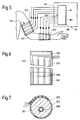
- FIGS. 5 and 7. An arm 301 with a large artery 303 is drawn in FIGS. 5 and 7.
- the device 311, likewise shown in FIG. 5, is designed to determine the blood pressure by detecting the electrical impedance or admittance.
- the device 311 has sensor means 313 with two sensors 321, 323 detachably attached to the arm 301, which in turn are spaced apart along the arm. For example, one, first sensor 321 is attached to the upper arm and the other, second sensor 323 is attached to the forearm.
- Each of the two sensors one of which can also be seen in FIGS. 6 and 7, has a sleeve 325 with a flexible, electrically insulating and possibly a little elastic band 327, which has four contact points on its side facing the arm when in use.
- Electrodes 329 is provided, which consist of flexible, electrically conductive metal foil strips running at a distance from one another parallel to the longitudinal direction of the tape.
- Velcro fastener elements 331, 333 are fastened to the band 327.
- the cuff 325 is used to carry out a measurement each sensor is wrapped around the arm 301 in such a way that the contact electrodes 329 abut it and completely surround it.
- the cuff is fastened at its overlapping end sections with the aid of the Velcro fastener elements 331, 333.
- a display and monitoring device 341 has electronic circuit means 343.
- Each contact electrode 329 is connected by a conductor of a cable to a feed and detector device 361 belonging to the circuit means 343.
- the latter has a generator or two generators in order to generate a supply voltage or a supply current with a frequency of 80 kHz to 100 kHz and to supply it to the two outermost electrodes of the two sensors 323.
- the or each generator can be designed to feed a current of constant amplitude into the arm 301 for each sensor.
- the feed and detector device 361 is further designed to detect the electrical impedance or admittance for each sensor from the electrical voltages that can be removed between the two inner electrodes of each sensor.
- the device 361 can furthermore form at least a first variable from the part of the impedance or admittance which changes in time with the pulse, which gives a measure of the volume.
- the volume of the blood in a blood vessel is proportional to its passage cross-sectional area and proportional to the square of the inner diameter of the blood vessel.
- the volumes, passage cross-sectional areas and diameter of the large arteries change - ie the brachial artery of the upper arm and the radial artery as well as the somewhat smaller ulnar artery of the forearm.
- the measurement of the impedance or admittance therefore also gives a measure of the passage cross-sectional area and of the inside diameter of at least one artery present in the measuring area.
- the electronic circuitry of device 341 may also be configured to be electrically through an analog or digital form of differentiation of the first derivative of the volume after time.
- the derivations or differential quotients determined for the two measuring ranges then each give a measure of the flow rate of the arterial blood in the arm regions detected by the two sensors.
- the device 311 thus makes it possible to determine a first size in the two measuring ranges, which gives a relative measure for the volume and / or the flow rate of the blood and / or for the passage cross-sectional area and / or the inside diameter of at least one blood vessel.
- the feed and detector device 361 is connected to an evaluation device (not shown) which, like the evaluation device 65, can determine the pulse wave speed from the time shift of the pulsating first variable detected by the two sensors.
- the evaluation device belonging to the electronic circuit means 343 can also be designed to determine the blood pressure from the measured values of the pulse wave velocity c pw measured in at least one measuring range for at least one of the variants measured as the first variable and the calibration values in an analogous manner to the evaluation device 65 blood pressure determined from v and c pw .
- the blood pressure according to the formula (5) would be proportional to the ratio Q / r4.
- Sensor means 413 which have two sensors 421, 423 for measuring the electrical impedance or admittance, are detachably attached to the arm 401 shown in FIG.
- the sensor means 413 differ from the sensor means 313 in that they have only six contact electrodes 429 in total. When measuring, the two outermost electrodes 429 introduce a high-frequency alternating current common to both sensors into the arm.
- the two sensors each have a cuff indicated by dash-dotted lines, but could also have a common cuff.
- the devices described with reference to FIGS. 5 to 8 can possibly still be changed by replacing some or all of the contact electrodes by electrodes which are electrically insulated from the body surface and which enclose the arm or another part of the body.
- the device could also be designed to measure the diameter of an artery, preferably a large artery, using ultrasound reflection as the first variable.
- the device can, for example, have sensors which, like sensors 121, 123, are provided with ultrasonic transducers 125.
- the electronic circuit means can then be designed to form electrical signals due to the reflection of ultrasound waves on at least a section of the arterial wall and preferably on two approximately diametrically opposed sections of the arterial wall, which signals measure the instantaneous values and / or temporal changes in the internal or external or average diameter or other cross-sectional dimensions and thus also the passage cross-sectional areas for the two sensors.
- the pulse wave speed can then be determined from the temporal shift between the periodic changes in the two sensors which are synchronous with the pulse and which result. Furthermore, blood pressure can be determined from the measured values and the entered calibration values. This can be done in a similar manner as was explained for the device 11 measuring the flow velocity described with reference to FIGS. 1 and 2.
- sensor means can also be provided which have only a single sensor for measuring the first variable.
- the pulse wave speed can then, for example - as also explained in the introduction - be determined from the influencing of the temporal course of the variables measured as the first variable caused by the reflection of the pulse waves.
- FIG. 9 contains two partial diagrams with a common abscissa, on which the time t is plotted.
- the flow velocity v is plotted on the ordinate in the upper part diagram.
- Curve 501 of the upper part diagram shows the somewhat schematic course of the flow velocity of the blood flowing through an artery during approximately one pulse period.
- the differential quotient dv / dt is plotted on the ordinate.
- curve 511 of the lower part diagram shows - likewise schematically - the course of the differential quotient mentioned.
- the flow velocity v begins to increase in the case of a heartbeat starting from a minimum value at time t o and reaches a main maximum 501a at time t 1, which coincides at least approximately with the occurrence of the systolic blood pressure.
- the flow velocity v then drops, reaches a relative intermediate minimum 501b at time t2, then rises again and reaches a secondary maximum 501c at time t3, in which the dicrotic node occurs in the blood pressure curve.
- the flow rate then drops again to approximately the initial minimum value.
- the curve 511 representing the course of the differential quotient dv / dt has accordingly at times t 1, t 2, t 3 each a zero crossing 511a or 511b or 511c, the zero line at zero crossings 511a and 511c from top to bottom and at Zero crossing 511b penetrates from bottom to top.
- the dicrotic knot and thus the associated secondary maximum 501c is caused by the interference of the primary pulse wave running away from the heart with a reflected pulse wave.
- the time difference T d between the two maxima 501a and 501c therefore gives a measure of the transit time of the reflected pulse waves and thus of the pulse wave speed.
- the electronic circuit means and in particular the evaluation device of the device provided for determining the pulse wave speed on the basis of the pulse wave reflection are designed to use the flow rate measured as the first variable to derive the first derivative over time - ie the differential quotient dv / dt - and preferably also the second derivative of time, ie to form the differential quotient d2v / dt2.
- This differentiation can be carried out electrically using a differentiating circuit in analog form or using a microprocessor in digital form.
- the circuit means can then identify the times t 1 and t 3 on the basis of the differential quotients and measure the time difference T d .
- the time difference T d or an associated variable, for example its reciprocal value, forms then the second quantity, which gives a measure of the pulse wave velocity, the value of which is represented in the form of a digital or analog, electrical signal.
- variable which gives a measure for the pulse wave velocity can be determined in a similar manner as was explained for the flow velocity v with reference to FIG.
- FIG. 10 shows a person with an arm 301 and a device for measuring blood pressure, designated 611 here.
- the sensor means 613 of the device 611 have only a single sensor 621 which is detachably attached to the arm 601. This has, for example, transducers for measuring the flow velocity by means of light or ultrasound, but could also be designed to determine a variable that can be used as the first variable by means of another measurement, for example an impedance or admittance measurement. However, the sensor means 613 still have contact electrodes, which are attached to the chest of the examined person and together form at least one sensor 623.
- the sensor 621 and the contact electrodes of the sensor 623 are connected to the display and monitoring device 641 via cables.
- the electronic circuit means of this are designed to detect at least one current of the heart muscle together with the contact electrodes of the sensor 623 analogously to electrocardiography and to determine the so-called R-wave of the cardiogram, in which the systole - ie the contraction of the Cardiac muscle - and the blood is emitted from the heart.
- the device 641 can then also determine the time difference between the R wave and the point in time at which the flow velocity of the blood in the arm 601 or the other first variable measured by the sensor 621 reaches the maximum value during a pulse period. These Time difference and its change or a quantity derived from this time difference and its change then give a measure of the pulse wave speed and its change.
- sensors can be provided which, like the sensors 21, 23, have light emitters and light receivers, but are arranged analogously to the sensors 121, 123 provided with an ultrasound transducer, in order to radiate light in a direction inclined towards the arm, so that then an optical Doppler effect measurement can be carried out.
- sensors can also be provided, each of which has a plurality of similar transducers which are offset from one another transversely to said artery. If such a sensor is attached, for example, to an arm containing the aforementioned large artery, it can be achieved without exact positioning of the sensor that the central radiation axis of one of its transducers crosses the large artery.
- the electronic circuit means can then be designed to automatically select the signal from the converter for further processing during measurement which is most strongly modulated by the pulse.
- the described devices and methods according to the invention all have the advantage that a long-term, continuous or at least quasi-continuous measurement of the blood pressure, for example taking place with every heartbeat, is possible, the examined person or possibly the examined animal being disturbed relatively little. It is particularly advantageous that only for A one-time calibration measurement or a few calibration measurements must or must be carried out using the Riva-Rocci method and that no cuff inflation and deflation is necessary for most of the measurement period.
- the method for blood pressure measurement and pulse rate measurement carried out using one of the described devices can be used commercially in therapy for long-term monitoring and furthermore, for example, also in examinations carried out in hospitals and possibly medical practices for the clarification of the general state of health, for human medicine as well as veterinary research and the development and testing of medicinal products are carried out.
Abstract
Description
Die Erfindung betrifft eine Einrichtung und ein Verfahren zur Blutdruckmessung.The invention relates to a device and a method for measuring blood pressure.
Die Einrichtung und das Verfahren dienen zur Blutdruckmessung, und zwar zur nicht-invasiven Blutdruckmessung. Der Begriff "nicht-invasiv" besagt hierbei, dass die Messung ohne in ein Blutgefäss eingeführtes Instrument und also mit Sensormitteln durchgeführt wird, die sich vollständig ausserhalb des lebenden, menschlichen oder eventuell tierischen Körpers befinden, an dem die Blutdruckmessung durchgeführt wird.The device and the method are used for blood pressure measurement, specifically for non-invasive blood pressure measurement. The term “non-invasive” here means that the measurement is carried out without an instrument inserted into a blood vessel and thus with sensor means that are located completely outside the living, human or possibly animal body on which the blood pressure measurement is carried out.
Der Blutdruck wird derzeit meistens mit Verfahren gemessen, die auf der Methode von Riva-Rocci basieren. Bekannte, für derartige Blutdruckmessungen vorgesehene Einrichtungen weisen eine deformierbare Manschette auf. Diese begrenzt einen Hohlraum, der mit einer üblicherweise durch eine Pumpe zum Pumpen von Luft gebildeten Druckgasquelle, einem Auslass und einer Druckmessvorrichtung verbunden ist. Ferner sind Mittel vorhanden, um beim Ändern des in der Manschette herrschenden Drucks - nämlich beim Entlüften der Manschette - zwei Werte dieses Drucks dem systolischen und dem diastolischen Druck zuordnen zu können. Die Zuordnung zum systolischen und zum diastolischen Druck kann dabei entweder aufgrund der vom Blut beim Durchströmen einer Arterie erzeugten Korotkoff-Töne oder nach der oszillometrischen Verfahrensvariante erfolgen. Bei bekannten, neueren Blutdruckmesseinrichtungen weisen die Druckmessvorrichtungen einen mit dem Hohlraum der Manschette verbundenen Messwandler zur Umwandlung des Druckes in eine elektrische Grösse, elektronische Schaltungsmittel und ein Anzeigeorgan zur analogen oder digitalen Anzeige des systolischen und diastolischen Blutdrucks auf. Einrichtungen für die Ermittlung des systolischen und diastolischen Blutdrucks aufgrund der Korotkoff-Töne weisen zudem entweder ein Stethoskop oder ein Mikrofon auf. Es sei hierbei zum Beispiel auf die deutsche Offenlegungsschrift 30 14 199 und die dieser entsprechenden US Patentschrift 4 459 991 verwiesen. Das pulsierende Fliessen des Blutes kann Schwingungen des in der Manschette vorhandenen, normalerweise aus Luft bestehenden Gases erregen. Bei den für die oszillometrische Messung vorgesehene Einrichtungen sind der Druck-Messwandler sowie die elektronischen Schaltungsmittel ausgebildet, um die mit den besagten Schwingungen verbundenen Schwankungen des in der Manschette herrschenden Drucks zu erfassen.Blood pressure is currently mostly measured using methods based on the Riva-Rocci method. Known devices provided for such blood pressure measurements have a deformable cuff. This delimits a cavity which is connected to a compressed gas source usually formed by a pump for pumping air, an outlet and a pressure measuring device. Means are also available in order to be able to assign two values of this pressure to the systolic and the diastolic pressure when changing the pressure prevailing in the cuff - namely when venting the cuff. The assignment to the systolic and to the diastolic pressure can take place either on the basis of the Korotkoff tones generated by the blood when flowing through an artery or according to the oscillometric method variant. In known, newer blood pressure measuring devices, the pressure measuring devices have a measuring transducer connected to the cavity of the cuff for converting the pressure into an electrical quantity, electronic switching means and a display element for analog or digital display of the systolic and diastolic blood pressure. Devices for determining the systolic and diastolic blood pressure based on the Korotkoff tones also have either a stethoscope or a microphone. Reference is made here, for example, to German Offenlegungsschrift 30 14 199 and the corresponding US Pat. No. 4,459,991. The pulsating flow of blood can excite vibrations of the gas normally present in the cuff. In the devices provided for the oscillometric measurement, the pressure transducer and the electronic circuit means are designed to detect the fluctuations in the pressure prevailing in the cuff associated with the said vibrations.
Beim Messen nach der Methode von Riva-Rocci wird die Manschette an einem Körperteil - zum Beispiel an einem Oberarm oder Finger befestigt und aufgepumpt, bis der Druck der in ihrem Hohlraum vorhandenen Luft ausreicht, um die Arterie im umschlossenen Glied abzuschnüren. Danach wird die Manschette langsam entlüftet. Bei der Variante mit Erfassung der Korotkoff-Töne mittels eines Stethoskops oder Mikrofons werden zwei Werte des während des Entlüftungsvorgangs im Hohlraum der Manschette herrschenden Drucks aufgrund der Geräusche als systolischer bzw. diastolischer Blutdruck identifiziert und erfasst. Dabei wird der beim ersten Auftreten von Korotkoff-Tönen in der Manschette herrschende Druck dem systolischen Blutdruck zugeordnet. Der diastolische Druck wird daran erkannt, dass die eigentlichen Korotkoff-Töne verschwinden, wobei die von der Blutströmung erzeugten Geräusche leiser und dumpfer werden oder ganz verschwinden. Bei der oszillometrischen Verfahrensvariante werden die den systolischen und den diastolischen Blutdrücken entsprechenden Drücke der in der Manschette enthaltenen Luft dadurch ermittelt, dass die durch das pulsierende Fliessen des Blutes verursachten Schwankungen des Manschettendrucks erstmals erscheinen bzw. wieder verschwinden.When measuring using the Riva-Rocci method, the cuff is attached to a part of the body - for example, an upper arm or finger and inflated until the pressure of the air in its cavity is sufficient to pinch off the artery in the enclosed limb. Then the cuff is slowly deflated. In the variant with recording the Korotkoff tones by means of a stethoscope or microphone, two values of the pressure prevailing in the cavity of the cuff during the ventilation process are identified and recorded as systolic or diastolic blood pressure due to the noise. The pressure prevailing in the cuff when Korotkoff tones first appear is assigned to the systolic blood pressure. The diastolic pressure is recognized by the fact that the actual Korotkoff tones disappear, and the sounds made by the blood flow become quieter and duller or disappear entirely. In the oscillometric method variant, the pressures of the air contained in the cuff corresponding to the systolic and diastolic blood pressures are determined by the fact that the fluctuations in the cuff pressure caused by the pulsating flow of the blood appear or disappear for the first time.
Bei schwer kranken oder schwer verunfallten und/oder frisch operierten Patienten sowie in anderen Fällen kann es notwendig oder zumindest wünschenswert sein, den Blutdruck des betreffenden Patienten während einer gewissen Zeitdauer - zum Beispiel während mehrerer Stunden oder Tage - dauernd und möglichst kontinuierlich zu überwachen. Aus der Praxis sind für diesen Zweck vorgesehene, nach der Methode von Riva-Rocci arbeitende Einrichtungen bekannt, bei denen die Manschette beim Betrieb automatisch zyklisch aufgepumpt und entlüftet werden kann, wobei während der Entlüftung jeweils der systolische und diastolische Blutdruck gemessen wird. Ein periodisches Aufpumpen sowie anschliessendes Entlüften der Manschette und die dabei jeweils stattfindende Unterbindung der Blutzirkulation im mit der Manschette versehenen Glied ist jedoch für den untersuchten Patienten unangenehm und eventuell sogar gesundheitsschädlich. Da ein Aufpump/Entlüftungszyklus meistens mindestens etwa eine Minute benötigt und da zudem zwischen aufeinanderfolgenden Messungen kleine Pausen eingeschaltet werden sollten, um die Störung des untersuchten Patienten möglichst gering zu halten, ermöglicht die Methode nach Riva-Rocci ferner gar keine wirklich kontinuierliche Blutdruckmessung.In seriously ill or seriously injured and / or freshly operated patients and in other cases, it may be necessary or at least desirable to monitor the patient's blood pressure continuously and as continuously as possible for a certain period of time - for example for several hours or days. Devices intended for this purpose and working according to the Riva-Rocci method are known in practice, in which the cuff can be automatically inflated and deflated during operation, the systolic and diastolic blood pressure being measured during the deflation. Periodic inflation and subsequent deflation of the cuff and the respective prevention of blood circulation in the limb provided with the cuff is uncomfortable for the examined patient and may even be harmful to health. Since an inflation / deflation cycle usually takes at least about one minute and since there should also be small pauses between successive measurements in order to keep the patient's disorder as low as possible, the Riva-Rocci method also does not allow a really continuous blood pressure measurement.
Die Publikation "Possible determinants of pulse-wave velocity in vivo", Masahiko Okada, IEEE Transactions on Biomedical Engineering, Vol. 35, Nr. 5, May 1988, Seiten 357 bis 361, offenbart ein photoplethysmographisches Verfahren für die Messung der noch näher erörterten Pulswellengeschwindigkeit. Die Messung erfolgt unter Verwendung von Licht mit einer Wellenlänge von 300 nm bis 500 nm an den Finger- oder Zehenspitzen. In dieser Publikation wird die Korrelation der Pulswellengeschwindigkeit mit verschiedenen anderen Parametern und Variablen beschrieben, unter denen sich auch der Blutdruck befindet. Gemäss dieser Publikation wurde eine gewisse Korrelation zwischen der Pulswellengeschwindigkeit und dem systolischen sowie diastolischen Blutdruck festgestellt. Eine solche, relativ geringe Korrelation ermöglicht aber keine Bestimmung des Blutdrucks. Da die Pulswellengeschwindigkeit nicht periodisch ändert, wäre es insbesondere auch nicht möglich, aus der Pulswellengeschwindigkeit den systolischen und den diastolischen Blutdruck zu ermitteln. Im übrigen sind die Wände der grossen Arterien und die diese meistens gegen aussen abdeckenden Gewebeteile für eine Wellenlänge von 300 nm bis 500 nm aufweisendes Licht praktisch undurchlässig. Das aus der Publikation von M. Okada bekannte Verfahren ist daher nur für Messungen an dünnwandigen, oberflächennahen und dementsprechend kleinen Blutgefässen und nicht für Messungen an grossen, entsprechend dickwandigen und eventuell relativ weit von der Oberfläche des untersuchten Körperteils entfernten Blutgefässen geeignet.The publication "Possible determinants of pulse-wave velocity in vivo", Masahiko Okada, IEEE Transactions on Biomedical Engineering, Vol. 35, No. 5, May 1988, pages 357 to 361, discloses a photoplethysmographic method for the measurement of those discussed in more detail Pulse wave velocity. The measurement is carried out using light with a wavelength of 300 nm to 500 nm at the tips of the fingers or toes. This publication describes the correlation of pulse wave velocity with various other parameters and variables, including blood pressure. According to this publication, a certain correlation between the pulse wave velocity and the systolic and diastolic blood pressure was found. Such, relatively low correlation does not allow blood pressure to be determined. Since the pulse wave speed does not change periodically, it would in particular also not be possible to determine the systolic and diastolic blood pressure from the pulse wave speed. For the rest, the walls of the large arteries and the light parts that mostly cover them against the outside for a wavelength of 300 nm to 500 nm are practically opaque. The method known from the publication by M. Okada is therefore only suitable for measurements on thin-walled, near-surface and accordingly small blood vessels and not for measurements on large, correspondingly thick-walled and possibly relatively far from the surface of the examined body part.
Der Erfindung liegt daher die Aufgabe zugrunde, eine Einrichtung und ein Verfahren zur nicht-invasiven Blutdruckmessung zu schaffen, wobei die Einrichtung und das Verfahren Nachteile der bekannten Einrichtungen bzw. Verfahren vermeiden und insbesondere ermöglichen soll, den Blutdruck eines Menschen oder eventuell Tieres im wesentlichen kontinuierlich zu überwachen, ohne dass abwechselnd eine Manschette aufgepumpt sowie entlüftet werden muss, wobei trotzdem eine gute Messgenauigkeit erreicht werden soll.The invention is therefore based on the object of providing a device and a method for non-invasive blood pressure measurement, the device and the method being intended to avoid disadvantages of the known devices and methods and, in particular, to enable the blood pressure of a person or possibly an animal to be essentially continuous to be monitored without having to alternately inflate and deflate a cuff, although good measurement accuracy is nevertheless to be achieved.
Im folgenden werden zunächst einige allgemeine, den Blutkreislauf betreffenden Eigenschaften erörtert. Der Blutkreislauf weist arterielle Blutgefässe - d.h. Arterien -, venöse Blutgefässe und die beiden Gefässarten miteinander verbindende Kapillargefässe auf. Die kleinsten, unmittelbar mit den Kapillargefässen verbundenen, arteriellen Blutgefässe oder Arterien werden als Arteriolen bezeichnet. Die arteriellen Blutgefässe haben elastisch deformierbare Wände und sind mindestens zum Teil mit Muskelfasern versehen und/oder von solchen umschlossen. Diese Muskelfasern können die Arterien und insbesondere die Arteriolen unterschiedlich stark zusammendrücken und dadurch die Elastizität, den Strömungswiderstand sowie die Blutverteilung auf die verschiedenen Blutgefässe beeinflussen. Das Herz pumpt das Blut pulsierend - d.h. stossweise - durch die Blutgefässe. Das Blut strömt mit einer Strömungsgeschwindigkeit v durch die Blutgefässe, die sowohl vom Ort als auch von der Zeit abhängig ist. Wenn man zur Vereinfachung zunächst annimmt, dass die Blutgefässe starre Wände haben, breiten sich Druckänderungen im Blut mit der Schallgeschwindigkeit cs aus, deren zweite Potenz gegeben ist durch die Formel![]()
![]()
Hierbei ist rho die Dichte des Blutes und K der Kompressionsmodul, der auch als Volumenelastizitätsmodul bezeichnet wird und gleich dem Reziprokwert der üblicherweise mit kappa bezeichneten Kompressibilität ist.Here rho is the density of the blood and K is the compression modulus, which is also referred to as the volume elastic modulus and is equal to the reciprocal of the compressibility usually designated with kappa.
In Wirklichkeit haben die arteriellen Blutgefässe jedoch nicht starre Wände, sondern - wie bereits erwähnt - elastisch deformierbare Wände. Die arteriellen Blutgefässe werden bei jedem durch einen Herzschlag verursachten Blutstoss und der damit verbundenen impulsartigen Druckerhöhung erweitert. Diese Erweiterungen breiten sich entlang den arteriellen Blutgefässen aus. Die Geschwindigkeit, mit der sich eine durch einen Herzschlag oder Blutstoss verursachte Druckänderung entlang einem arteriellen Blutgefäss unter der Einwirkung von dessen Wandelastizität ausbreitet, bildet die schon erwähnte Pulswellengeschwindigkeit cpw. Gemäss dem Buch "Führer durch die Strömungslehre", Ludwig Prandtl, Verlag Friedr. Vieweg & Sohn, Braunschweig, 1965, ist die zweite Potenz der Ausbreitungsgeschwindigkeit von Druckänderungen in Rohren mit elastisch dehnbaren Wänden bei Vernachlässigung von Biegeschwingungen und damit mindestens näherungsweise auch die zweite Potenz der Pulswellengeschwindigkeit gegeben durch die Formel![]()
![]()
Dabei ist E der Elastizitätsmodul der Blutgefässwand, s die Dicke der Blutgefässwand und d der Innendurchmesser des Blutgefässes.E is the modulus of elasticity of the blood vessel wall, s the thickness of the blood vessel wall and d the inside diameter of the blood vessel.
Gemäss der schon zitierten Publikation von M. Okada ist die Pulswellengeschwindigkeit im Quadrat gegeben durch die Formel![]()
![]()
Durch Einsetzen von cs in die Formel (2) kann man zeigen, dass die Formel (3) aus der Formel (2) hervorgeht, wenn man in der letzteren zur Vereinfachung im Klammerausdruck den zweiten Summanden weglässt.By inserting c s into the formula (2) it can be shown that the formula (3) emerges from the formula (2) if, in the latter, the second addend is omitted in the parentheses for simplicity.
Die Strömungsgeschwindigkeit des Blutes ist - wie schon erwähnt - sowohl orts- als auch zeitabhängig. Ihr Maximalwert beträgt in einem arteriellen Blutgefäss und insbesondere in einer grossen Arterie eines erwachsenen Menschen höchstens etwa 0,5 m/s und normalerweise etwas weniger. Die Pulswellengeschwindigkeit ist gemäss den Formen (2) und (3) vom Verhältnis zwischen der Wanddicke und dem Durchmesser der Arterien abhängig. Da sich dieses vom Herzen zu den Kapillargefässen hin vergrössert und da die Pulswellengeschwindigkeit zudem vom Elastizitätsmodul und von der Spannung der zum betreffenden Blutgefäss gehörenden Muskelfasern abhängig ist, ändert sich die Pulswellengeschwindigkeit entlang den arteriellen Blutgefässen und ist auch vom Zustand der untersuchten Menschen oder Tiere abhängig. In den Arterien beträgt die Pulswellengeschwindigkeit typischerweise etwa 4 m/s bis 5 m/s. Die Schallgeschwindigkeit in Wasser, das ja den Hauptbestandteil des Blutes bildet, liegt in der Grösse von 1500 m/s. Die Pulswellengeschwindigkeit cpw ist also wesentlich, nämlich mindestens oder ungefähr 10 Mal grösser als die Strömungsgeschwindigkeit v und die Schallgeschwindigkeit cs ist wiederum sehr viel grösser als die Pulswellengeschwindigkeit.The flow velocity of the blood is - as already mentioned - dependent on location and time. Their maximum value in an arterial blood vessel and in particular in a large artery of an adult human being is at most about 0.5 m / s and usually somewhat less. According to forms (2) and (3), the pulse wave velocity depends on the ratio between the wall thickness and the diameter of the arteries. Since this increases from the heart to the capillary vessels and since the pulse wave speed also depends on the elastic modulus and the tension of the muscle fibers belonging to the blood vessel in question, the pulse wave speed changes along the arterial blood vessels and is also dependent on the condition of the people or animals examined. In the arteries, the pulse wave speed is typically around 4 m / s to 5 m / s. The speed of sound in water, which is the main constituent of the blood, is around 1500 m / s. The pulse wave velocity c pw is therefore essential, namely at least or approximately 10 times greater than the flow velocity v and the speed of sound c s is again much greater than the pulse wave speed.
Der sich in einem bestimmten Blutgefäss ergebende Blutdruck hängt von der Pumpleistung des Herzens, vom Strömungswiderstand des Blutgefässes, von der momentanen Durchflussmenge, von der Elastizität der Blutgefässwand und von der Viskosität des Blutes ab.The blood pressure resulting in a certain blood vessel depends on the pumping power of the heart, on the flow resistance of the blood vessel, on the current flow rate, on the elasticity of the blood vessel wall and on the viscosity of the blood.
Die gestellte Aufgabe wird durch eine Einrichtung und ein Verfahren mit den Merkmalen des Anspruchs 1 bzw. 14 gelöst. Vorteilhafte Ausgestaltungen der Einrichtung und des Verfahrens gehen aus den abhängigen Ansprüchen hervor.The object is achieved by a device and a method having the features of claims 1 and 14, respectively. Advantageous refinements of the device and the method emerge from the dependent claims.
Es wurde nämlich gefunden, dass sich der Blutdruck relativ genau dadurch bestimmen lässt, dass zwei verschiedene Grössen ermittelt werden, wobei als eine, erste Grösse bei mindestens einem Messbereich kontinuierlich eine zeitlich periodisch im Takt des Pulses ändernde Variable und/oder deren pulsbedingte Änderung und als andere, zweite Grösse eine Grösse ermittelt wird, die ein Mass für die Pulswellengeschwindigkeit und/oder deren Änderung gibt. Unter Verwendung von mindestens einem nach der weiter vorne beschriebenen Methode von Riva-Rocci ermittelten Eichwert kann dann durch Verknüpfen der beiden Grössen mindestens eine Grösse gebildet werden, die ein Mass für einen charakteristischen Wert des Blutdrucks und/oder dessen Änderung gibt, wobei zum Beispiel mindestens der systolische und zum Beispiel auch noch der diastolische und/oder mittlere Blutdruck gemessen und angezeigt werden kann.It has been found that the blood pressure can be determined relatively precisely by determining two different variables, the first variable in at least one measuring range being continuously a variable that changes periodically in time with the pulse and / or its pulse-related change and as other, second variable a variable is determined which gives a measure of the pulse wave velocity and / or its change. Using at least one calibration value determined by the Riva-Rocci method described above, at least one variable can then be formed by linking the two variables, which gives a measure of a characteristic value of the blood pressure and / or its change, for example at least the systolic and for example also the diastolic and / or mean blood pressure can be measured and displayed.
Die Einrichtung besitzt Sensormittel, die zum Beispiel mindestens einen lösbar an einen Körperteil befestigten Sensor aufweisen, wobei etwa zwei gleichartige oder zwei verschiedenartige Sensoren vorhanden sein können. Zumindest der bzw. jeder zur Messung der ersten, periodisch ändernden Grösse dienende Sensor wird vorzugsweise an einem Arm oder eventuell einem Bein befestigt. Die Einrichtung besitzt ferner vorzugsweise eine durch ein Gerät oder mehrere solche gebildete Anzeige- und Überwachungsvorrichtung, die mindestens einen Teil der elektronischen Schaltungsmittel der Einrichtung enthält.The device has sensor means which, for example, have at least one sensor detachably attached to a body part, it being possible for there to be approximately two identical or two different types of sensors. At least the or each for measuring the first, periodically changing variable serving sensor is preferably attached to an arm or possibly a leg. The device also preferably has a display and monitoring device, formed by a device or a plurality of such devices, which contains at least part of the electronic circuit means of the device.
Die genannte erste, zeitlich synchron mit dem Puls ändernde Grösse ändert auch synchron zum Blutdruck - d.h. im gleichen Takt wie dieser - und ist mit dem Blutdruck durch eine physikalische Verknüpfung korreliert, soll aber selbstverständlich verschieden vom Blutdruck und nicht bereits direkt durch den Blutdruck selbst bzw. dessen Änderung gebildet sein. Die Sensormittel und elektronischen Schaltungsmittel können ausgebildet sein, um als erste Grösse eine Grösse zu ermitteln und durch ein elektrisches Signal darzustellen, die ein Mass für den momentanen Wert und/oder die synchron mit dem Puls erfolgende Änderung der Strömungsgeschwindigkeit und/oder der Durchflussmenge und/oder des Volumens des Blutes in einem Messbereich und/oder einer Querschnittsabmessung und/oder der Durchlassquerschnittsfläche mindestens eines arteriellen Blutgefässes gibt. Da die Blutgefässe und insbesondere die Arterien im Querschnitt normalerweise mindestens annähernd kreisförmig sind, kann die genannte, allenfalls ermittelte Querschnittsabmessung mindestens näherungsweise durch den Innen- oder Aussendurchmesser oder einen mittleren Durchmesser des Blutgefässes gebildet sein. Es sei hierzu noch angemerkt, dass die für die erste Grösse angegebenen Variablen eng miteinander verknüpft sind. Wenn man die Durchflussmenge in Volumeneinheiten pro Zeiteinheit misst, so ist die Durchflussmenge nämlich gleich dem Produkt der über die Querschnittsfläche gemittelten, mittleren Strömungsgeschwindigkeit mal der Durchlassquerschnittsfläche des Blutgefässes.The first variable mentioned, which changes in time synchronously with the pulse, also changes synchronously with the blood pressure - ie at the same rate as this - and is correlated with the blood pressure by a physical link, but should of course be different from the blood pressure and not already directly through the blood pressure itself or its change must be formed. The sensor means and electronic circuit means can be designed to determine a size as a first variable and to represent it by an electrical signal, which is a measure of the instantaneous value and / or the change in the flow velocity and / or the flow rate and / or the flow rate and / or the volume of the blood in a measuring area and / or a cross-sectional dimension and / or the passage cross-sectional area of at least one arterial blood vessel. Since the blood vessels and in particular the arteries are usually at least approximately circular in cross-section, the cross-sectional dimension mentioned, if any, can be at least approximately formed by the inside or outside diameter or an average diameter of the blood vessel. It should also be noted that the variables given for the first size are closely linked. If one measures the flow rate in volume units per unit of time, the flow rate is namely the product of the average flow velocity averaged over the cross-sectional area times the passage cross-sectional area of the blood vessel.
Die Einrichtung kann zum Beispiel ausgebildet sein, um als erste Grösse die Strömungsgeschwindigkeit und/oder Durchflussmenge zu erfassen, indem Lichtwellen - nämlich monochromatische, kohärente Lichtwellen - oder Ultraschallwellen in einen zu untersuchenden Körperteil eingestrahlt und vom Blut oder - genauer gesagt - von den Blutkörperchen gestreute Lichtwellen bzw. Ultraschallwellen aufgefangen werden. Die Einstrahlung der Licht- bzw. Ultraschallwellen kann dabei impulsweise erfolgen. Bei diesen auf der Streuung von Licht oder Ultraschall beruhenden Verfahren können je nach Wunsch rechtwinklig und/oder parallel zur Einstrahlungsrichtung des Lichts bzw. Ultraschalls gerichtete Komponenten der Strömungsgeschwindigkeit oder des Durchflusses erfasst werden. Es sind verschiedene Arten von solchen auf der Streuung von Licht oder Ultraschall basierende Messmethoden bekannt. Bei Verwendung von Licht können die Messungen zum Beispiel mit Hilfe der Photonen-Korrelation, der Licht-Schwebungs-Spektroskopie, (englisch: "light beating spectroscopy"), der Tupfen-Interferometrie (englisch: "speckle interferometry") oder des Dopplereffekts erfolgen. Es sei hierzu beispielsweise auf die Publikation "Laser doppler anemometry, a comparative study of the measurement of motion by light scattering", E.R. Pike, in "The engineering uses of coherent optics", "Proceedings and edited discussion of a conference held at the University of Strathclyde, Glasgow" 8. - 11. April 1975, Seiten 431 bis 457, Cambridge University Press, verwiesen.The device can be designed, for example, to detect the flow rate and / or flow rate as the first variable, in that light waves - namely monochromatic, coherent light waves - or ultrasound waves are radiated into a part of the body to be examined and scattered by the blood or - more precisely - by the blood cells Light waves or ultrasonic waves are collected. The irradiation of the light or ultrasonic waves can take place in pulses. In these methods, which are based on the scattering of light or ultrasound, components of the flow velocity or flow directed at right angles and / or parallel to the direction of irradiation of the light or ultrasound can be detected, as desired. Various types of measurement methods based on the scattering of light or ultrasound are known. When using light, the measurements can be carried out, for example, with the aid of photon correlation, light-beating spectroscopy (English: "light beating spectroscopy"), spot interferometry (English: "speckle interferometry") or the Doppler effect. For example, reference is made to the publication "Laser doppler anemometry, a comparative study of the measurement of motion by light scattering", E.R. Pike, in "The engineering uses of coherent optics", "Proceedings and edited discussion of a conference held at the University of Strathclyde, Glasgow" April 8-11, 1975, pages 431-457, Cambridge University Press.
Bei der Verwendung von Ultraschall können die Messungen auf ähnliche Arten, nämlich zum Beispiel mit Hilfe der Zeit-Domänen-Korrelation (englisch: "time domain correlation"), des Interferenz-Tupfen-Musters (englisch: "interference speckle pattern") und/oder der Fourier-Transformation oder des Dopplereffekts erfolgen. Einige solche Messmethoden sind zum Beispiel in folgenden Aufsätzen in den "Proceedings zum IEEE Ultrasonics Symposium" 1990, Band 3 beschrieben: "An improved blood velocity estimator optimized for real-time ultrasound flow applications", M.R. Sturgill, R.H. Love, B.K. Herres, Seiten 1467 bis 1471; "Preliminary study into high velocity transverse blood flow measurement", H.F. Routh, T.L. Pusateri, D.D. Waters, Seiten 1523 bis 1526 und "Determination of 2-D velocity vectors using color Doppler ultrasound", T. Tamura, R.S.C. Cobbold, K.W. Johnston, Seiten 1537 bis 1540. Ferner sei noch die Publikation "A novel method for angle independent ultrasonic imaging of blood flow and tissue motion", L.N. Bohs, G.E. Trahey, IEEE Transactions on Biomedical Engineering, Band 38, No. 3, 1991, Seiten 280 bis 286, hingewiesen.When using ultrasound, the measurements can be carried out in similar ways, for example using the time-domain correlation, the interference speckle pattern and / or the Fourier transform or the Doppler effect. Some such measurement methods are described, for example, in the following essays in the "Proceedings of the IEEE Ultrasonics Symposium" 1990, Volume 3: "An improved blood velocity estimator optimized for real-time ultrasound flow applications ", MR Sturgill, RH Love, BK Herres, pages 1467 to 1471;" Preliminary study into high velocity transverse blood flow measurement ", HF Routh, TL Pusateri, DD Waters, pages 1523 to 1526 and" Determination of 2-D velocity vectors using color Doppler ultrasound ", T. Tamura, RSC Cobbold, KW Johnston, pages 1537 to 1540. Furthermore, there is also the publication" A novel method for angle independent ultrasonic imaging of blood flow and tissue motion ", LN Bohs, GE Trahey , IEEE Transactions on Biomedical Engineering, Volume 38, No. 3, 1991, pages 280 to 286.
Zu den verschiedenen auf der Streuung von Lichtwellen oder Ultraschallwellen beruhenden Methoden sei noch angemerkt, dass diese von den verschiedenen Autoren und Gerätherstellern zum Teil etwas uneinheitlich bezeichnet werden. Beispielsweise werden den Dopplereffekt-Vertahren zum Teil auch noch Verfahren zugeordnet, bei denen eine zur Strahlungsrichtung rechtwinklige Strömungsgeschwindigkeit gemessen wird, obschon unter dem Dopplereffekt strenggenommen und im klassischen Sinn die Erzeugung einer Frequenzverschiebung durch eine zur Wellenausbreitungsrichtung parallele Geschwindigkeitskomponente einer Wellenstrahlungsquelle verstanden wird.Regarding the different methods based on the scattering of light waves or ultrasonic waves, it should be noted that these are sometimes called somewhat inconsistently by the various authors and device manufacturers. For example, the Doppler effect processes are sometimes also assigned methods in which a flow velocity perpendicular to the direction of radiation is measured, although strictly speaking the Doppler effect is understood to mean the generation of a frequency shift by a speed component of a wave radiation source that is parallel to the direction of wave propagation.
Falls eine Ermittlung der Strömungsgeschwindigkeit und/oder Durchflussmenge mittels Licht vorgesehen ist, kann die Einrichtung einen oder mehrere Lichtstrahler und einen oder mehrere Lichtempfänger aufweisen. Der oder jeder Sensor kann dann zum Beispiel mindestens einen als Lichtstrahler dienenden, optoelektronischen Wandler, zum Beispiel eine Laser-Leuchtdiode, und mindestens einen als Lichtempfänger dienenden, optoelektronischen Wandler, zum Beispiel eine Photodiode oder einen Phototransistor, aufweisen. Diese Wandler können dann über ein flexibles, elektrisches Kabel mit dem oder einem Gerät der Anzeige- und Überwachungsvorrichtung verbunden sein. Es besteht jedoch auch die Möglichkeit, mindestens einen oder jeden optoelektronischen Wandler im genannten Gerät anzuordnen und über einen flexiblen Lichtleiter mit einem Sensor zu verbinden. In diesem Fall enthalten dann die Sensoren als Lichtstrahler und/oder Lichtempfänger bzw. von diesen nur noch das eine Ende des betreffenden Lichtleiters und beispielsweise noch ein optisches Übertragungselement.If a determination of the flow rate and / or flow rate by means of light is provided, the device can have one or more light emitters and one or more light receivers. The or each sensor can then have, for example, at least one optoelectronic converter serving as a light emitter, for example a laser light-emitting diode, and at least one optoelectronic converter serving as a light receiver, for example a photodiode or a phototransistor. These transducers can then be connected to the or a device of the display and monitoring device via a flexible electrical cable. However, there is also the option of at least one or Arrange each optoelectronic converter in the device mentioned and connect it to a sensor via a flexible light guide. In this case, the sensors then contain as light emitters and / or light receivers or only one end of the light guide in question and, for example, an optical transmission element.
Bei einer vorteilhaften Ausgestaltung einer Einrichtung zur Messung der Strömungsgeschwindigkeit oder Durchflussmenge mit Hilfe der Lichtstreuung wird mit mindestens einem Lichtstrahler Licht erzeugt, dessen Wellenlänge im nahen Infrarotbereich liegt und mindestens 700 nm, höchstens 1200 nm und zum Beispiel 800 nm bis 1000 nm beträgt. Derartiges Licht kann relativ dicke Gewebeschichten und vor allem auch die Wände grosser Arterien durchdringen, so dass die Strömungsgeschwindigkeit und/oder Durchflussmenge nicht nur in kleinen, sondern auch in grossen Arterien gemessen werden kann.In an advantageous embodiment of a device for measuring the flow rate or flow rate with the aid of light scattering, light is generated with at least one light emitter, the wavelength of which is in the near infrared range and is at least 700 nm, at most 1200 nm and for example 800 nm to 1000 nm. Such light can penetrate relatively thick layers of tissue and, above all, the walls of large arteries, so that the flow rate and / or flow rate can be measured not only in small but also in large arteries.
Bei der Ermittlung der Strömungsgeschwindigkeit und/oder Durchflussmenge unter Verwendung von Ultraschall kann der oder jeder Sensor mindestens einen Wandler aufweisen, der ein piezoelektrisches Element besitzt und sowohl einen Ultraschallstrahler zum Einstrahlen von Ultraschallimpulsen in einen Körperteil als auch einen Ultraschallempfänger zum Aufnehmen von zurückgestreutem Ultraschall bildet.When determining the flow rate and / or flow rate using ultrasound, the or each sensor can have at least one transducer which has a piezoelectric element and forms both an ultrasound emitter for irradiating ultrasound pulses into a body part and an ultrasound receiver for receiving backscattered ultrasound.
Eine andere Möglichkeit besteht darin, die Einrichtung auszubilden, um aufgrund einer Messung der elektrischen Impedanz oder Admittanz eine erste Grösse zu ermitteln, die ein Mass für das zeitlich ändernde Volumen des in einem Messbereich eines Körperteils vorhandenen Blutes und/oder des Durchmessers und/oder der Durchlassquerschnittsfläche von mindestens einer im Messbereich vorhandenen Arterie und/ oder von der Blut-Durchflussmenge gibt. Die Einrichtung kann Sensormittel mit Elektroden aufweisen, die entlang einer im betreffenden Körperteil vorhandenen, grossen Arterie in Abstand voneinander derart lösbar am betreffenden Körperteil befestigt werden, dass sie diesen mindestens zum grössten Teil und beispielsweise vollständig umschliessen. Die Einrichtung besitzt vorzugsweise einen Hochfrequenz-Generator, um eine Wechselspannung zu erzeugen und mindestens zwei Elektroden zuzuführen. Die Frequenz der Wechselspannung kann etwa im Bereich von 30 kHz bis 3 MHz liegen und beträgt nämlich vorzugsweise mindestens 70 kHz, höchstens 150 kHz und beispielsweise 80 kHz bis 100 kHz. Für weitere allgemeine Information zu dieser Variante der Messmethode sei auf die Publikationen "The measurement of peripheral blood flow by the electrical inpedance technique", S.N. Mohapatra, H.M. Arenson, Journal of Medical Engineering and Technology, Band 3, No. 3, 1979, Seite 132 bis 137 und "Digital enhancement of the peripheral admittance plethysmogram", L.A. Marks, IEEE Transactions on Biomedical Engineering, Band BME-34, No. 3, 1987, Seiten 192 bis 197, verwiesen.Another possibility is to design the device to determine a first variable based on a measurement of the electrical impedance or admittance, which is a measure of the time-changing volume of the blood present in a measurement area of a body part and / or the diameter and / or the Passage cross-sectional area of at least one artery present in the measurement area and / or of the blood flow rate. The device can have sensor means with electrodes that run along a large artery in the relevant body part Distance from each other so releasably attached to the body part in question that they at least for the most part and completely surround, for example. The device preferably has a high-frequency generator in order to generate an alternating voltage and to supply at least two electrodes. The frequency of the alternating voltage can be approximately in the range from 30 kHz to 3 MHz and is namely preferably at least 70 kHz, at most 150 kHz and for example 80 kHz to 100 kHz. For further general information on this variant of the measurement method, reference is made to the publications "The measurement of peripheral blood flow by the electrical inpedance technique", SN Mohapatra, HM Arenson, Journal of Medical Engineering and Technology,
Die Strömungsgeschwindigkeit des Blutes kann auch induktiv mit mindestens eine Spule aufweisenden Sensormitteln gemessen werden. Die bzw. jede Spule kann derart lösbar an einem Arm oder andern Körperteil befestigt werden, dass die Spulenachse ungefähr rechtwinklig zu einer grossen Arterie verläuft und diese vorzugsweise mindestens annähernd kreuzt.The flow rate of the blood can also be measured inductively with sensor means having at least one coil. The or each coil can be releasably attached to an arm or other body part in such a way that the coil axis runs approximately at right angles to a large artery and preferably crosses it at least approximately.
Ferner kann als erste Grösse eine ein Mass für den Durchmesser einer grossen Arterie gebende Grösse ermittelt werden, indem die Reflexion von Ultraschall an der Arterienwand verwertet wird. Aus dem Durchmesser kann dann selbstverständlich auch die Durchlassquerschnittsfläche der Arterie bestimmt werden.Furthermore, a size which gives a measure of the diameter of a large artery can be determined as the first size by utilizing the reflection of ultrasound on the artery wall. The passage cross-sectional area of the artery can of course also be determined from the diameter.
Zur Bestimmung der Pulswellengeschwindigkeit und/oder der zeitlichen Änderung von dieser bestehen ebenfalls verschiedene Möglichkeiten. Die Sensormittel und elektronischen Schaltungsmittel können zum Beispiel ausgebildet sein, um die erste, synchron zum Puls zeitlich ändernde Grösse - d.h. Variable-bei zwei entlang dem Strömungsweg des arteriellen Blutes, insbesondere entlang einer grossen Arterie, voneinander im Abstand stehenden Mess-Stellen oder Messbereiche zu ermitteln und durch elektrische Signale darzustellen. Des weitern kann die Zeitdifferenz ermittelt werden, um welche die zeitlichen Verläufe der bei den zwei Messbereichen ermittelten, ersten Grösse - beispielsweise die Maxima der ersten Grösse - gegeneinander verschoben sind. Bei festgelegtem Abstand der beiden Messbereiche ist die Pulswellengeschwindigkeit dann umgekehrt proportional zur besagten Zeitdifferenz. Die zweite Grösse kann ebenfalls in Form eines elektrischen Signals dargestellt werden und also beispielsweise durch die genannte Zeitdifferenz und/oder durch deren Reziprokwert und/oder direkt durch die Pulswellengeschwindigkeit gebildet sein.There are also various possibilities for determining the pulse wave velocity and / or the change over time thereof. The sensor means and electronic circuit means can, for example, be designed to receive the first, The time-changing variable synchronous to the pulse - ie variable - at two measuring points or measuring ranges spaced apart from one another along the flow path of the arterial blood, in particular along a large artery, and to be represented by electrical signals. Furthermore, the time difference can be determined by which the time profiles of the first variable determined in the two measuring ranges - for example the maxima of the first variable - are shifted from one another. If the distance between the two measuring ranges is fixed, the pulse wave speed is then inversely proportional to the said time difference. The second variable can also be represented in the form of an electrical signal and can thus be formed, for example, by the time difference mentioned and / or by its reciprocal value and / or directly by the pulse wave speed.
Die von einem Herzen erzeugten Pulswellen breiten sich von diesem weg entlang von arteriellen Blutgefässen zu den Kapillargefässen aus und werden von diesen mit mehr oder weniger stark reduzierter Amplitude reflektiert. Wie nun erläutert wird, ermöglicht diese Reflexion der Pulswellen, aus dem zeitlichen Verlauf der bei einem einzigen Messbereich gemessenen, ersten Grösse eine zweite Grösse abzuleiten, die ein Mass für die Pulswellengeschwindigkeit gibt. Eine entlang einer Arterie vom Herzen weglaufende Pulswelle wird im folgenden als primäre Pulswelle bezeichnet. Da eine grosse Arterie - wie etwa diejenige eines Arms oder Beins - normalerweise über mehrere entlang von ihr verteilte Verzweigungen mit Kapillargefässen verbunden ist, können von verschiedenen Kapillargefässen reflektierte Pulswellen zur genannten, grossen Arterie zurückgelangen und sich in dieser zu einer grössern, reflektierten Pulswelle überlagern, die ihrerseits der primären Pulswelle überlagert wird und also mit dieser interferiert. Der sich bei einer bestimmten Mess-Stelle der grossen Arterie ergebende Gangunterschied zwischen der primären Pulswelle und der reflektierten Pulswelle ist von der Pulswellengeschwindigkeit und von der Entfernung der die Reflexion bewirkenden Kapillargefässe vom Messbereich abhängig. Wenn sich der Messbereich an einem Arm befindet, erfolgt die Reflexion vor allem in der viele Kapillargefässe enthaltenden Hand, so dass der besagte Gangunterschied massgeblich durch die Entfernung der Hand vom Messbereich bestimmt wird. Bei einer Messung an einem Bein, ist analog die Entfernung des Fusses vom Messbereich massgebend für den Gangunterschied. Die den zeitlichen Verlauf des Blutdruckes wiedergebende Kurve hat in jeder Periode ein Haupt-Maximum, dessen Wert gleich dem systolischen Blutdruck ist, und ein durch die Interferenz zwischen einer primären und einer reflektierten Pulswelle verursachtes mehr oder weniger ausgeprägtes, kleineres Neben-Maximum, das in der Fachsprache als dikrotischer Knoten (englisch: "dicrotic notch") bezeichnet wird. Im übrigen befindet sich der dikrotische Knoten jeweils im abfallenden Teil der Blutdruckkurve, d.h. zwischen einem systolischen Blutdruckwert und dem nachfolgenden diastolischen Blutdruckwert. Die Strömungsgeschwindigkeit und die andern angegebenen Variablen, welche die erste zu messende Grösse bilden können, werden bei wachsendem Blutdruck grösser und bei abnehmendem Blutdruck kleiner. Dementsprechend haben die zeitlichen Verläufe der als erste Grösse genannten Variablen bei jedem Herzschlag ein dem systolischen Druck zugeordnetes Haupt-Extremum, nämlich Haupt-Maximum, und ein dem dikrotischen Knoten zugeordnetes Neben-Extremum, nämlich Neben-Maximum und dazwischen ein relatives Zwischen-Minimum. Die zeitliche oder phasenmässige Verschiebung zwischen einem Haupt-Extremum und dem diesem zeitlich benachbarten, nachfolgenden Neben-Extremum ist vom Gangunterschied zwischen der primären Pulswelle sowie der reflektierten Pulswelle und damit auch von der Pulswellengeschwindigkeit abhängig. Die Sensormittel und Schaltungsmittel können daher ausgebildet sein, um bei einem Messbereich aus dem zeitlichen Verlauf der für die erste Grösse ermittelten Variablen als zweite Grösse die Zeitdifferenz und/oder Phasenwinkeldifferenz zwischen dem Haupt-Extremum sowie einem benachbarten, nachfolgenden Extremum, nämlich dem Neben-Maximum oder eventuell dem Zwischen-Minimum, zu bilden und in Form eines elektrischen Signals darzustellen.The pulse waves generated by a heart propagate away from it along arterial blood vessels to the capillary vessels and are reflected by them with a more or less greatly reduced amplitude. As will now be explained, this reflection of the pulse waves makes it possible to derive a second variable from the time course of the first variable measured in a single measuring range, which second variable gives a measure of the pulse wave velocity. A pulse wave running away from the heart along an artery is referred to below as the primary pulse wave. Since a large artery - such as that of an arm or leg - is usually connected to capillaries via several branches distributed along it, pulse waves reflected from different capillaries can return to the large artery mentioned and overlap in it to form a larger, reflected pulse wave, which in turn is superimposed on the primary pulse wave and thus interferes with it. The path difference between the primary pulse wave and the reflected pulse wave that results at a specific measuring point of the large artery is of Pulse wave speed and the distance of the capillaries causing reflection from the measuring range. If the measuring area is located on one arm, the reflection mainly takes place in the hand containing many capillaries, so that the said path difference is largely determined by the distance of the hand from the measuring area. When measuring on one leg, the distance of the foot from the measuring area is also decisive for the gait difference. The curve representing the time course of the blood pressure has a main maximum in each period, the value of which is equal to the systolic blood pressure, and a more or less pronounced, smaller secondary maximum caused by the interference between a primary and a reflected pulse wave the technical term is called dicrotic knot (English: "dicrotic notch"). Otherwise, the dicrotic node is located in the falling part of the blood pressure curve, ie between a systolic blood pressure value and the subsequent diastolic blood pressure value. The flow velocity and the other specified variables, which can form the first variable to be measured, become greater with increasing blood pressure and smaller with decreasing blood pressure. Accordingly, the time profiles of the variables named as the first variable have a main extremum, namely the main maximum, assigned to the systolic pressure, and a secondary extremum, namely a secondary maximum and a relative intermediate minimum, which is assigned to the dicrotic node. The temporal or phase-related shift between a main extremum and the subsequent secondary extremum that is adjacent to it in time is dependent on the path difference between the primary pulse wave and the reflected pulse wave and thus also on the pulse wave speed. The sensor means and circuit means can therefore be designed to determine the time difference and / or phase angle difference between the main extremum as the second variable in a measuring range from the time profile of the variables determined for the first variable and to form an adjacent, subsequent extremum, namely the secondary maximum or possibly the intermediate minimum, and to present it in the form of an electrical signal.
Eine weitere Möglichkeit zur Ermittlung der Pulswellengeschwindigkeit besteht darin, die Sensormittel und die elektronischen Schaltungsmittel auszubilden, um bei einem Messbereich eine der als erste Grösse genannten Variablen und zusätzlich analog wie bei der Elektrokardiographie mindestens einen Strom des Herzmuskels zu erfassen und die sogenannte R-Zacke des Kardiogramms zu ermitteln, bei welcher die Systole - d.h. die Kontraktion des Herzmuskels - und der Blutausstoss aus dem Herzen erfolgt. Wie schon beschrieben, hat die Strömungsgeschwindigkeit oder sonstige, die erste Grösse bildende Variable währende Pulsperiode ein im gleichen Zeitpunkt wie der systolische Blutdruck auftretendes Maximum. Die Einrichtung kann daher ferner ausgebildet sein, um die Zeitdifferenz zwischen bestimmten, vorgegebenen, in jeder Pulsperiode einmal vorhandenen Stellen der Kurven zu ermitteln, welche die zeitlichen Verläufe des Herzmuskelstroms und der als erstgenannten Grösse gemessenen Variablen darstellen. Dabei kann zum Beispiel die Zeitdifferenz zwischen der R-Zacke der Herzmuskelstrom-Kurve und dem Zeitpunkt ermittelt werden, in dem die erste Grösse während einer Pulsperiode ein Maximum hat. Diese Zeitdifferenz oder ihre Änderung und/oder eine mit dieser Zeitdifferenz und deren Änderung verknüpfte Grösse können dann als zweite Grösse dienen, die ein Mass für die Pulswellengeschwindigkeit bzw. deren Änderung gibt.A further possibility for determining the pulse wave speed is to design the sensor means and the electronic circuit means in order to detect at least one current of the heart muscle and the so-called R-wave of the heart muscle in a measuring range, as one of the variables mentioned as the first variable, and additionally analogously to electrocardiography Determine the cardiogram at which the systole - ie the contraction of the heart muscle - and the blood is expelled from the heart. As already described, the flow velocity or other pulse period forming the first variable has a maximum occurring at the same time as the systolic blood pressure. The device can therefore also be designed to determine the time difference between specific, predetermined positions of the curves which are present once in each pulse period and which represent the time profiles of the heart muscle current and the variables measured as the first-mentioned variable. For example, the time difference between the R wave of the heart muscle current curve and the point in time at which the first variable has a maximum during a pulse period can be determined. This time difference or its change and / or a variable linked to this time difference and its change can then serve as a second variable which gives a measure of the pulse wave velocity or its change.
Der Erfindungsgegenstand wird anschliessend anhand in der Zeichnung beschriebener Ausführungsbeispiele näher erläutert. In der Zeichnung zeigt
- die Figur 1 eine schematische Ansicht einer Einrichtung zur Blutdruckmessung mit am Arm einer Person angeordneten Sensormitteln,
- die
Figur 2 einen schematischen Längsschnitt durch Abschnitte des Arms sowie der an diesem befestigten, Licht-strahler und Lichtempfänger aufweisenden Sensormittel und ein Blockschema elektronischer Schaltungsmittel der Einrichtung, - die
Figur 3 einen schematischen Längsschnitt durch Abschnitte eines Arms sowie der an diesem befestigten, Ultraschall-Wandler aufweisenden Sensormittel, - die
Figur 4 einen der Figur 3 entsprechenden Längsschnitt durch Abschnitte eines Arms und andersartige Ultraschall-Wandler aufweisende Sensormittel, - die
Figur 5 eine schematische Ansicht einer Variante einer Blutdruckmess-Einrichtung mit am Arm einer Person angeordneten Sensormittel, die zwei Sensoren mit Elektroden zur Messung der elektrischen Impedanz oder Admittanz aufweisen, - die
Figur 6 eine Draufsicht auf die zum Anliegen am Arm bestimmte Seite von einem vom Arm entfernten Sensor der Einrichtung gemäss der Figur 5 in grösserem Massstab, - die
Figur 7 einen stark vereinfachten Querschnitt durch den inder Figur 5 ersichtlichen Arm und einen der an diesem befestigten Sensoren in noch grösserem Massstab als dieFigur 6, - die
Figur 8 eine schematische Ansicht einer Variante von an einem Arm angeordneten Sensormitteln mit Elektroden für die Messung der elektrischen Impedanz oder Admittanz, - die Figur 9 ein Diagramm in zu Veranschaulichung der Ermittlung der Pulswellengeschwindigkeit aufgrund der Reflexion der Pulswellen und
- die Figur 10 eine schematische Ansicht einer Person und einer Blutdruckmess-Einrichtung, die zur Ermittlung der Pulswellengeschwindigkeit durch Erfassen eines Herzmuskelstroms ausgebildet ist.
- FIG. 1 shows a schematic view of a device for measuring blood pressure with sensor means arranged on the arm of a person,
- FIG. 2 shows a schematic longitudinal section through sections of the arm and the sensor means attached to it, having light emitters and light receivers, and a block diagram of electronic circuit means of the device,
- FIG. 3 shows a schematic longitudinal section through sections of an arm and the sensor means attached to it and having ultrasonic transducers,
- FIG. 4 shows a longitudinal section corresponding to FIG. 3 through sections of an arm and different sensor means having ultrasonic transducers,
- 5 shows a schematic view of a variant of a blood pressure measuring device with sensor means arranged on the arm of a person, which have two sensors with electrodes for measuring the electrical impedance or admittance,
- FIG. 6 shows a plan view on a larger scale of the side intended to rest on the arm from a sensor of the device according to FIG. 5 which is removed from the arm,
- FIG. 7 shows a greatly simplified cross section through the arm shown in FIG. 5 and one of the sensors attached to it on an even larger scale than FIG. 6,
- FIG. 8 shows a schematic view of a variant of sensor means arranged on an arm with electrodes for measuring the electrical impedance or admittance,
- FIG. 9 shows a diagram to illustrate the determination of the pulse wave speed on the basis of the reflection of the pulse waves and
- FIG. 10 shows a schematic view of a person and a blood pressure measuring device, which is designed to determine the pulse wave velocity by detecting a heart muscle current.
In der Figur 1 ist ein Körperteil 1, nämlich ein Arm 1 eines lebenden, menschlichen Körpers dargestellt. Der zum Teil auch schematisch sowie vereinfacht in der Figur 2 gezeichnete Arm 1 enthält Blutgefässe. Zu diesen gehört eine grosse, entlang dem ganzen Arm verlaufende Arterie 3, von welcher Abschnitte der im Unterarm vorhandenen Arteria radialis gezeichnet sind und die eine durch einen Blutstoss erzeugte, fortschreitende Erweiterung 3a aufweist. Die Arterie 3 ist durch entlang von ihr verteilte und abgezweigte, kleinere Arterien 4 und Arteriolen 5 mit den einen Enden von Kapillargefässen 6 verbunden. Dabei sind insbesondere viele Arteriolen vorhanden, die nahe der Körperoberfläche in und/oder unter der Haut und mindestens annähernd parallel zu dieser verlaufen. Die nicht mit Arteriolen 5 zusammenhängenden Enden der Kapillargefässe 6 sind über Venolen 7 mit grössern Venen 8 verbunden.1 shows a body part 1, namely an arm 1 of a living human body. The arm 1, which is also shown partially schematically and simplified in FIG. 2, contains blood vessels. These include a
Eine in den Figuren 1 und 2 ersichtliche Einrichtung 11 dient zur Blutdruckmessung sowie zur Pulsfrequenzmessung und weist aussen am Arm 1 - nämlich am Unterarm - angeordnete Sensormittel 13 auf. Diese haben einen lösbar am Arm 1 befestigten Halter 15 mit einem länglichen, plättchen- oder streifenförmigen, beispielsweise ein wenig flexiblen, aus elektrisch isolierendem Kunststoff bestehenden Haltekörper 17, dessen Längsrichtung ungefähr parallel zu derjenigen des Arms ist und der auf einer Seite an diesem anliegt. Die lösbare Befestigung des Halters 15 kann zum Beispiel mit nicht gezeichneten, lösbaren Klebeverbindungsmitteln erfolgen, die etwa einen zwischen dem Arm 1 und dem Haltekörper 17 angeordneten, beidseitig klebenden Klebstreifen und/oder mindestens einen auf der Aussenseite des Halters 15 an diesem und auch am Arm angeklebten Klebstreifen aufweisen. Statt Klebeverbindungsmittel kann der Halter 15 auch mit einer den Arm 1 umschliessenden Manschette versehen werden, die einen Klettverschluss oder irgend einen anderen Verschluss aufweist.A
Der Halter 15 hält einen ersten Sensor 21 und einen zweiten Sensor 23. Die beiden Sensoren 21, 23 stehen in der Längsrichtung des Arms 1 sowie der Arterie 3 voneinander in Abstand und sind beispielsweise lösbar oder unlösbar am Haltekörper 17 befestigt, etwa festgeklebt. Jeder Sensor 21, 23 besitzt ein beispielsweise im wesentlichen zylindrisches Gehäuse 25, in welchem mindestens ein Lichtstrahler 27 und mindestens ein Lichtempfänger 29 angeordnet sind. Die Lichtstrahler 27 und Lichtempfänger 29 der beiden Sensoren weisen je einen optoelektronischen Wandler, nämlich eine Laser-Leuchtdiode bzw. eine Photodiode auf. Die Laser-Leuchtdioden der Lichtstrahler erzeugen beim Betrieb kohärentes, monochromatisches Licht dessen Wellenlänge 780 bis 820 nm und nämlich beispielsweise ungefähr 810 nm beträgt. Wie schon in der Einleitung dargelegt, kann derartiges, im nahen Infrarotbereich liegendes Licht, die im Arm vorhandenen Gewebe und die Wände aller im Arm 1 vorhandenen Arterien - also insbesondere auch der grossen Arterie 3 - durchdringen. Die Lichtstrahler 27 der beiden Sensoren 21, 23 sind derart angeordnet, dass ihre Strahlungsachsen - d.h. die Mittelachsen der von ihnen in den Arm 1 eingestrahlten Lichtwellenbündel - ungefähr rechtwinklig zur Oberfläche und zur Längsrichtung des Arms 1 und zur Arterie 3 verlaufen. Die Lichtempfänger 29 sind ebenfalls derart angeordnet, dass sie Licht aufnehmen können, das ungefähr rechtwinklig zur Oberfläche des Arms 1 aus diesem austritt. Die Sensoren 21, 23 können beispielsweise durch je einen Lichtstrahler und Lichtempfänger aufweisende Sensoren gebildet sein, wie sie von der Firma Moor Instruments Ltd., Devon, Grossbritannien, für die von dieser Firma unter der Typen-Bezeichnung MBF3D hergestellten Zweikanal-Blutströmungsmonitoren geliefert werden. Die Sensoren 21, 23 können dabei derart angeordnet werden, dass die Strahlungsachsen entweder die grosse Arterie 3 kreuzen oder dies nicht tun.The
Der in der Figur 2 mit a bezeichnete Abstand der beiden Sensoren 21, 23 voneinander beträgt vorzugsweise mindestens 3 cm. Insbesondere wenn die Lichtstrahler nicht auf die grosse Arterie 3 ausgerichtet werden, ist es vorteilhaft, wenn der Abstand a relativ gross ist und beispielsweise mindestens oder ungefähr 6 cm beträgt. Wenn die beiden Sensoren gemäss der Figur 1 am Unterarm angeordnet werden, kann der Abstand a beispielsweise bis etwa 10 cm oder eventuell sogar bis etwa 15 cm betragen. Es sei jedoch eingefügt, dass man auch den einen Sensor am Oberarm und den andern Sensor am Unterarm befestigen kann, wobei dann der entlang dem gestreckten Arm gemessene Abstand noch grösser als die vorgängig angegebene Werte sein kann. Die zwei Sensoren 21, 23 haben zum Beispiel einen etwa 7 mm betragenden Durchmesser sowie eine in der Grösse von 5 mm liegende, axiale Abmessung. Die Sensormittel 13 beanspruchen also nur wenig Platz, haben nur ein geringes Gewicht und enthalten im Gegensatz zu den nach der Methode von Riva-Rocci arbeitenden Einrichtungen keine aufzublähende und zu entlüftende Manschette und auch sonst keine beim noch näher beschriebenen Messen zu deformierenden und/oder zu bewegenden Teile, so dass sie den Patienten, an dem sie angebracht sind, nur wenig stören.The distance a between the two
Die beiden Sensoren 21, 23 der Sensormittel 13 sind durch ein elektrisches Kabel 35 elektrisch leitend mit einem in Abstand vom untersuchten Menschen etwa auf einem Tisch oder einer Konsole eines Bettgestells angeordneten Anzeige- und Überwachungsvorrichtung 41 verbunden. Diese weist ein Gerät mit einem Gehäuse auf, könnte aber auch durch mehrere Geräte mit separaten Gehäusen gebildet sein. Die Vorrichtung 41 besitzt im und/oder am Gehäuse angeordnete, elektronische Schaltungsmittel 43 mit dem in der Figur 2 gezeichneten Blockschema, mindestens eine Anzeigevorrichtung 45 zur digitalen und/oder analogen Anzeige verschiedener Messgrössen und manuell betätigbare, zum Beispiel drück- und/oder dreh-und/oder kippbare Schalt- und/oder Stellorgane 47. Ferner ist eine Alarmiervorrichtung 51 mit mindestens einem optischen Alarmsignalgeber 53 und nämlich mit mehreren solchen vorhanden, die etwa aus Leuchtdioden und/oder Lämpchen bestehen. Die Alarmiervorrichtung 51 kann ferner noch mindestens einen akustischen Alarmsignalgeber aufweisen und/oder elektrisch mit einem solchen verbunden sein. Falls die Einrichtung in einem Spital benutzt wird, kann übrigens noch vorgesehen werden, dass die Vorrichtungen 41 mehrerer Einrichtungen über elektrische Leiter oder drahtlos Alarmsignale und eventuell Messwerte auf eine zentrale Überwachungs- und Alarmiervorrichtung übertragen können, die optische und/oder akustische Alarmsignalgeber aufweist.The two
Die elektronischen Schaltungsmittel 43 weisen eine elektrisch leitende mit den optoelektronischen Wandlern der Lichtstrahler 27 und Lichtempfänger 29 der beiden Sensoren 21, 23 verbundene Speise- und Detektorvorrichtung 61 auf. Diese besitzt mindestens eine beispielsweise durch einen Impulsgenerator gebildete Erregerspannungsquelle, um mindestens eine beispielsweise aus einer Impulsfolge bestehende Erregerspannung zu erzeugen und den Lichtstrahlern 27 zuzuführen, so dass diese Licht - beispielsweise Lichtimpulse - in den Arm einstrahlen. Bei der Benutzung der Einrichtung gelangt von den Blutkörperchen des den Arm 1 durchströmenden, arteriellen Blutes reflektiertes oder - genauer gesagt - zurückgestreutes Licht in die Lichtempfänger 29, deren Wandler dieses Licht in elektrische Signale umwandeln. Die Speise- und Detektorvorrichtung 61 besitzt nun des weitern Schaltungsmittel, um aufgrund des rückgestreuten Lichts die Strömungsgeschwindigkeiten des pulsierenden, arteriellen Blutes in den von den beide Sensoren 21, 23 erfassten Messbereichen des Arms 1 zu ermitteln. Die Vorrichtung 61 kann dann elektrische Signale oder Grössen bilden, die in analoger oder digitaler Form ein Mass für die momentanen, Werte der genannten Strömungsgeschwindigkeiten des Blutes geben. Die Speise- und Detektorvorrichtung 61 kann die Strömungsgeschwindigkeiten gleich oder ähnlich ermitteln, wie es in der in der Einleitung zitierten Literatur für quer zur Strömungsrichtung gerichtete Lichtstrahlen beschrieben ist. Die Vorrichtung 61 kann ferner zum Beispiel gleich oder ähnlich ausgebildet sein, wie die Schaltung in den bereits erwähnten, unter der Typen-Bezeichnung MBF3D der Firma Moor Instruments Ltd. erhältlichen Zweikanal-Blutströmungsmonitoren.The electronic circuit means 43 have an electrically conductive feed and
Die Anzeige- und Überwachungsvorrichtung besitzt noch eine Eichwerteingabevorrichtung 63 mit elektronischen Schaltungsmitteln, die mit mindestens einem der manuell betätigbaren Betätigungsorgane 47 verbunden sind.The display and monitoring device also has a calibration
Die Speise- und Detektorvorrichtung 61 ist mit einer Auswertungsvorrichtung 65 verbunden und führt dieser beim Messen die erwähnten, ein Mass für die Strömungsgeschwindigkeiten bei den beiden Sensoren 21, 23 gebenden, elektrischen Signale oder Grössen zu. Die Eichwerteingabevorrichtung 63 ist ebenfalls mit der Auswertungsvorrichtung 65 verbunden, um dieser beim Eichen durch elektrische Signale oder Grössen in analoger oder digitaler Form dargestellte Eichwerte zuzuführen. Die Auswertungsvorrichtung 65 weist vorzugsweise einen Mikroprozessor, mindestens einen Speicher für die Speicherung digital dargestellter Daten und nötigenfalls Analog/Digital- und/oder Digital/Analogwandler auf. Die Auswertungsvorrichtung 65 hat Ausgänge, die mit der Anzeige-vorrichtung 45 und mit der Alarmiervorrichtung 51 verbunden sind. Es sei hier noch angemerkt, dass die im in der Figur 2 ersichtlichen Blockschema gezeichnete Aufteilung der elektronischen Schaltungsmittel 43 auf drei funktionelle Blöcke-d.h. Vorrichtungen 61, 63 und 65 - nur schematisch ist und dass beispielsweise gewisse Teile dieser Blöcke oder Vorrichtungen durch ein- und dieselbe integrierte Schaltung und/oder durch ein und denselben Mikroprozessor gebildet sein können.The feed and
Nun sollen noch einige Aspekte der Messung näher erläutert werden. Wie bereits erwähnt, gelangt beim Betrieb der Einrichtung von den Blutkörperchen des arteriellen Bluts reflektiertes bzw. zurückgestreutes Licht in die Lichtempfänger 29 der beiden Sensoren 21, 23. Dabei kann zusätzlich zu dem vom arteriellen Blut reflektierten Licht auch Licht in die Lichtempfänger gelangen, das von venösem Blut oder von Gewebeteilen oder irgendwelchen andern Komponenten des Arms 1 gestreut wurde. Da jedoch von dem in die Lichtempfänger gelangenden Licht nur dasjenige zeitlich im Takt des Pulses variiert, das vom pulsierenden, arteriellen Blut gestreut wurde, kann die Speise- und Detektorvorrichtung 61 den pulsierenden Lichtanteil herausfiltern oder in anderer Weise erkennen und eben die Strömungsgeschwindigkeit des arteriellen Blutes ermitteln.Now some aspects of the measurement will be explained in more detail. As already mentioned, during operation of the device, light reflected or backscattered by the blood cells of the arterial blood reaches the
Wie bereits in der Einleitung erörtert, verursacht das stossweise Pumpen des Blutes periodische und zum Puls synchrone, zeitliche Blutdruckänderungen, die sich mit der Pulswellengeschwindigkeit ausbreiten. Jedes infolge eines Herzschlages entstehende Druckmaximum ist mit einem Maximum der Strömungsgeschwindigkeit verknüpft und verursacht in der Arterie 3 die bereits erwähnte Erweiterung 3a, die mit der Pulswellengeschwindigkeit cpw in der Strömungsrichtung des Blutes entlang der Arterie 3 fortschreitet. Die Strömungsrichtung des Blutes und die Ausbreitungrichtung der Druckänderung sowie der Erweiterung 3a sind in der Figur 2 durch einen Pfeil bezeichnet. Die Erweiterung oder - genauer gesagt - deren Maximum passiert zuerst den ersten Sensor 21 und dann nach einer Laufzeit Ta den im Abstand a vom ersten Sensor stehenden, zweiten Sensor 23. Die sich bei den beiden Sensoren in der Arterie 3 ergebenden Maxima der Strömungsgeschwindigkeiten sind dementsprechend um die Laufzeit Ta zeitlich gegeneinander verschoben. Die beiden Sensoren können - wie erwähnt - derart angeordnet sein, dass die von ihren Lichtstrahlern erzeugten Lichtstrahlenbündel die grosse Arterie 3 kreuzen. Wenn dies zutrifft, kann vom die Arterie 3 durchströmenden Blut reflektiertes Licht in die Lichtempfänger gelangen. In einem solchen Fall kann direkt die Strömungsgeschwindigkeit von die Arterie 3 durchströmendem Blut ermittelt werden. Unter dieser Voraussetzung und unter der Voraussetzung, dass der sich zwischen den beiden Sensoren 21, 23 befindende Abschnitt der Arterie 3 gerade ist sowie parallel zur Verbindungsgeraden zwischen den Zentren der am Arm anliegenden Flächen der beiden Sensoren verläuft, kann die Pulswellengeschwindigkeit errechnet werden gemäss der Formel![]()
![]()
In Wirklichkeit ist die Arterie 3 normalerweise nicht genau parallel zur erwähnten, die Sensoren verbindenden Verbindungsgeraden. Die Pulswellengeschwindigkeit ist dann aber immer noch umgekehrt proportional zur Laufzeit Ta.In reality,
Wie erwähnt, können die Sensoren auch derart angeordnet werdend, dass die in den Arm 1 gestrahlten Lichtstrahlenbündel nicht die grosse Arterie 3, sondern nur kleinere arterielle Blutgefässe, insbesondere mehr oder weniger zur Oberfläche des Arms parallele Arteriolen 5, kreuzen. Da diese Arteriolen durch relativ kurze, kleine Arterien 4 mit der grossen Arterie 3 verbunden sind, ist der zeitliche Verlauf der Pulswelle in den Arteriolen 5 nur relativ wenig gegen den zeitlichen Verlauf der Pulswelle in denjenigen Abschnitten der grossen Arterien 3 verschoben, die sich in den Messbereichen befinden, bei denen die Sensoren angeordnet sind. Zumindest wenn der Abstand a so gross gewählt wird, dass die in den Messbereichen der beiden Sensoren vorhandenen Arteriolen bei entlang der Arterie 3 in Abstand voneinander stehenden Abzweigungen mit dieser verbunden sind, ist die Pulswellengeschwindigkeit dann ebenfalls mindestens annähernd durch die Formel (4) bestimmt und jedenfalls noch proportional zum Reziprokwert der Laufzeit Ta.As mentioned, the sensors can also be arranged in such a way that the light beams radiated into the arm 1 do not cross the
Die Auswertungsschaltung 65 ist ausgebildet, um aus den beiden ihr von der Speise- und Detektorvorrichtung 65 zugeführten Folgen von Signalen die Laufzeit Ta zu ermitteln und ein elektrisches, vorzugsweise digitales Signal zu erzeugen, das ein Mass für die Pulswellengeschwindigkeit gibt. Aus den mit den beiden Sensoren ermittelten Messwerten können also die relativen Werte von zwei Grössen ermittelt und durch elektrische Signale dargestellt werden, von denen die eine ein Mass für die Strömungsgeschwindigkeit bei einem der beiden Sensoren 21, 23 und die andere ein Mass für die Pulswellengeschwindigkeit in der Arterie 3 gibt. Da die Strömungsgeschwindigkeit im Takt des Pulses variiert, können die elektronischen Schaltungsmittel 43 auch die Pulsfrequenz ermitteln. Zudem können die Schaltungsmittel ausgebildet sein, um eventuell noch den Amplitudenwert oder den zeitlichen Mittelwert der pulsierenden Strömungsgeschwindigkeit zu ermitteln und durch ein elektrisches Signal darzustellen. Ferner können die Schaltungsmittel zum Beispiel auch den Mittelwert der bei den beiden Sensoren gemessenen Amplitudenwerte oder zeitlichen Mittelwerte der Strömungsgeschwindigkeiten bilden.The
Für das Durchführen einer kontinuierlichen Messung des Blutdrucks wird die Einrichtung 11 mit Hilfe einer zusätzlichen, nur vorübergehend und nur während einer im Vergleich zur ganzen Messdauer kurzen Zeit benutzten, strichpunktiert in der Figur 1 angedeuteten Eich-Messvorrichtung 71 geeicht. Diese weist eine aufblähbare Manschette 73 sowie ein mit dieser verbundenes Messgerät 75 auf und ist zum Messen des Blutdrucks nach der Methode von Riva-Rocci ausgebildet. Zum Eichen wird die Manschette 73 nach dem Befestigen der Sensormittel 13 am Arm 1 vorübergehend an einem Körperteil, und zwar am Oberarm des andern Arms 2 angebracht. Hierzu ist anzumerken, dass die Manschette 73 und die Sensormittel 13 vorzugsweise nicht entlang dem gleichen Blutströmungsweg angeordnet werden sollten, weil das Abschnüren der Blutströmung durch die Manschette und die nach dem Entfernen der Manschette noch während einer gewissen Zeitdauer vorhandenen Nachwirkungen der Abschnürung Messfehler verursachen könnten. Mit Hilfe von einem Schalt- und/oder Stellorgan 47 bringt man dann die Anzeige- und Überwachungsvorrichtung 41 der Einrichtung 11 in einen Eichmodus, d.h. in eine zum Eichen vorgesehene Betriebsart, misst gleichzeitig mit der zusätzlichen Eich-Messvorrichtung 71 nach der Methode von Riva-Rocci in einer der in der Einleitung beschriebenen Arten die Werte des systolischen Blutdrucks ps sowie des diastolischen Blutdrucks pd sowie eventuell noch gewisse Zwischenwerte des Blutdrucks. Diese mit der Eich-Messvorrichtung ermittelten Eichwerte werden dann manuell mit mindestens einem der Schalt- und/oder Stellorgane 47 über die Eichwerteingabevorrichtung 63 in die Auswertungsschaltung 65 eingegeben. Es besteht jedoch auch die Möglichkeit, die Anzeige- und Überwachungsvorrichtung 41 und die Eich-Messvorrichtung 71 derart auszubilden, dass die beiden Vorrichtungen 41 und 71 beim Eichen vorübergehend über ein Kabel und Steckverbindungen miteinander verbunden werden können. In diesem Fall kann ferner vorgesehen werden, dass die Eich-Messvorrichtung 71 der Vorrichtung 41 mindestens einen Teil der zum Eichen der Einrichtung 11 erforderlichen Eichwerte automatisch in Form elektrischer Signale zuführt. Wenn die Einrichtung 11 auf die eine oder andere Weise geeicht wurde, kann die Manschette 73 der Eich-Messvorrichtung 71 wieder vom Arm 1 entfernt werden, während die Sensormittel 13 bis zum Ende der vorgesehenen Messdauer am Arm 1 befestigt bleiben.In order to carry out a continuous measurement of the blood pressure, the
Wenn sich die Messung über längere Zeit - zum Beispiel über mehrere Tage - erstreckt, kann die Einrichtung 11 mit Hilfe der Eich-Messvorrichtung 71 von Zeit zu Zeit - zum Beispiel ein Mal täglich - neu geeicht werden.If the measurement extends over a longer time - for example over several days - the
Nun soll erläutert werden, wie aus den gemessenen Werten Strömungsgeschwindigkeit sowie der Pulswellengeschwindigkeit und den Eichwerten der Blutdruck ermittelt werden kann. Hierzu wird zunächst angenommen, dass ein beim Messen erfasstes Blutgefäss aus einem kreiszylindrischen Rohr mit einer starken Wand besteht. Die in Volumeneinheiten pro Zeiteinheit gemessene Durchflussmenge Q durch ein Rohr mit einer starren Wand, dem Innenradius r und der Länge L ist bei laminarer Strömung gemäss dem Gesetz von Hagen-Poiseuille gegeben durch die Formel![]()
![]()
Dabei bezeichnet pL die über einem Rohrstück mit der Länge L vorhandene Druckdifferenz und eta den dynamischen Viskositäts-koeffizienten.Here, p L denotes the pressure difference present over a piece of pipe with the length L and eta the dynamic viscosity coefficient.
Wenn die in der Formel (5) auf beiden Seiten des Gleichheitszeichens stehenden Grössen durch die Innen- oder Durchlassquerschnittsfläche F des vorderhand als starrwandiges Rohr betrachteten Blutgefässes dividiert, ergibt sich für die Strömungsgeschwindigkeit![]()
![]()
Unter der vereinfachenden Annahme, dass die Blutgefässe starre Wände haben, ist der momentane Blutdruck p proportional zur Druckdifferenz pL und also gemäss den Formeln (5) und (6) proportional zur momentanen Durchflussmenge Q und zur momentanen Strömungsgeschwindigkeit v. Unter der genannten Annahme und unter der Voraussetzung, dass die Viskosität des Blutes während einer Messung konstant bleibt, kann also die Verknüpfung des Blutdrucks p mit der Strömungsgeschwindigkeit v dargestellt werden durch die Formel![]()
![]()
Wie weiter vorne erörtert, sind jedoch die Wände der arteriellen Blutgefässe in Wirklichkeit elastisch dehnbar, so dass sich bei einem Druckanstieg zusätzlich zur Strömungsgeschwindigkeit des Blutes auch der Innenradius r sowie dieAs discussed earlier, however, the walls of the arterial blood vessels are in reality elastically stretchable, so that in addition to the flow velocity of the blood, the inner radius r and also increase when the pressure increases
Durchlassquerschnittsfläche der Blutgefässe vergrössert.Passage cross-sectional area of the blood vessels enlarged.
Wenn man ein Blutgefäss als Rohr mit einer elastisch dehnbaren Wand auffasst, ist die relative Dehnung epsilon des Umfangs sowie auch des Durchmessers gegeben durch die Formel![]()
![]()
Dabei bezeichnet mü die Querkontraktionszahl der Blutgefässwand und D den Aussendurchmesser des Blutgefässes.Here, mü denotes the transverse contraction number of the blood vessel wall and D the outer diameter of the blood vessel.
Die Dehnung eines Blutgefässes ist also vom Verhältnis zwischen dem Blutdruck p und dem Elastizitätsmodul E abhängig. Selbstverständlich ist umgekehrt auch die Dehnung und damit der Blutdruck vom Elastizitätsmodul abhängig. Zum Beispiel bewirkt eine Verkleinerung der Dehnbarkeit - bei konstant bleibender Förderleistung des Herzens - eine Vergrösserung des Blutdrucks. Der Innenradius r und Elastizitätsmodul E der Blutgefässwände hängen von der Art der beim Messen erfassten Blutgefässe, von der individuellen anatomischen Konfiguration der untersuchten Person und auch vom physiologischen Zustand der Blutgefässe ab. Zum Beispiel ist der Elastizitätsmodul bei einem jungen Sportler kleiner als bei einem alten, an Arteriosklerose leidenden Menschen. Zudem kann der Innenradius und/oder der Elastizitätsmodul während der Messzeitdauer relativ schnell ändern. Eine solche Änderung kann etwa durch eine Änderung der Spannung der zur Wand der Arterie gehörenden Muskelfasern verursacht werden. Die Spannung von zu arteriellen Blutgefässen gehörenden Muskelfasern kann zum Beispiel geändert werden, wenn für die Verdauung vorübergehend ein grösserer Teil des Blutstromes zu den Verdauungsorganen geleitet wird oder wenn die Durchblutung der Haut zur Anpassung an Änderungen der Umgebungstemperatur geändert wird. Des weitern kann die Spannung der besagten Muskelfasern auch durch die Tätigkeit und den Gemütszustand der untersuchten Person beeinflusst werden. Der Elastizitätsmodul E der Blutgefässwände ist jedoch gemäss der Formel (2) oder (3) mit der Pulswellengeschwindigkeit cpw verknüpft. Die Pulswellengeschwindigkeit oder eine daraus abgeleitete Grösse gibt daher ein Mass für den relativen Wert des Elastizitätsmoduls.The elongation of a blood vessel is therefore dependent on the relationship between the blood pressure p and the modulus of elasticity E. Conversely, of course, the stretch and thus the blood pressure also depend on the modulus of elasticity. For example, a reduction in the elasticity - while the heart's output remains constant - causes an increase in blood pressure. The inner radius r and modulus of elasticity E of the blood vessel walls depend on the type of blood vessels detected during the measurement, on the individual anatomical configuration of the person examined and also on the physiological state of the blood vessels. For example, the modulus of elasticity is smaller in a young athlete than in an old person suffering from arteriosclerosis. In addition, the inner radius and / or change the modulus of elasticity relatively quickly during the measurement period. Such a change can be caused, for example, by a change in the tension of the muscle fibers belonging to the wall of the artery. The tension of muscle fibers belonging to arterial blood vessels can be changed, for example, if a larger part of the blood flow is temporarily directed to the digestive organs for digestion or if the blood supply to the skin is changed to adapt to changes in the ambient temperature. Furthermore, the tension of the said muscle fibers can also be influenced by the activity and the state of mind of the person examined. However, the modulus of elasticity E of the blood vessel walls is linked to the pulse wave velocity c pw according to formula (2) or (3). The pulse wave velocity or a quantity derived from it therefore gives a measure of the relative value of the elastic modulus.
Wenn v ändert, ist also r² in der Formel (7) in Wirklichkeit abweichend von der vorherigen Annahme nicht konstant, sondern ändert ebenfalls. Da die zusätzlich zur Strömungsgeschwindigkeit v gemessene Pulswellengeschwindigkeit cpw gemäss der Formel (2) oder (3) ein Mass für den Elastizitätsmodul E gibt, kann der Einfluss der Elastizität beim Auswerten der Messwerte v und cpw durch die Auswertungsvorrichtung 65 berücksichtigt werden.So if v changes, r² in formula (7) is in reality not constant, deviating from the previous assumption, but also changes. Since the pulse wave velocity c pw measured in addition to the flow velocity v gives a measure of the elasticity module E according to formula (2) or (3), the influence of the elasticity when evaluating the measured values v and c pw can be taken into account by the
Es wurden Vergleichsmessungen durchgeführt, bei denen gleichzeitig mit der erfindungsgemässen Einrichtung die Strömungsgeschwindigkeit v sowie die Pulswellengeschwindigkeit cpw und mit der Eich-Messvorrichtung 71 nach der Methode von Riva-Rocci der Blutdruck gemessen wurde. Gemäss diesen Vergleichsmessungen besteht bei konstanter Pulswellengeschwindigkeit cpw eine sehr enge Korrelation zwischen dem Blutdruck p und der Strömungsgeschwindigkeit v sowie auch der Durchflussmenge Q. Wenn hingegen die Pulswellengeschwindigkeit ändert, so ändert auch die Verknüpfung des Blutdrucks mit der Strömungsgeschwindigkeit.Comparative measurements were carried out in which the flow velocity v and the pulse wave velocity c pw were measured simultaneously with the device according to the invention and the blood pressure was measured with the calibration measuring device 71 using the Riva-Rocci method. According to these comparative measurements, there is a very close correlation between the blood pressure p and the flow velocity v and also the flow rate Q at a constant pulse wave velocity c pw . However, if the pulse wave velocity changes, so does the link between blood pressure and flow velocity.
Bei einer bestimmten, konstanten Pulswellengeschwindigkeit ist also jedem Wert von v in eindeutiger Weise ein Wert von p zugeordnet. Wenn die Pulswellengeschwindigkeit ändert, verursacht dies auch eine Änderung der Verknüpfung zwischen v und p. Dabei ergibt sich aber bei jedem beliebigen, aber gleichbleibenden Wert der Pulswellengeschwindigkeit eben eine eindeutige Verknüpfung zwischen v und p.At a certain, constant pulse wave velocity, each value of v is uniquely assigned a value of p. When the pulse wave speed changes, it also causes the link between v and p to change. However, with any, but constant value of the pulse wave velocity, there is a clear link between v and p.
Wie bereits erwähnt, kann die Auswertungsvorrichtung 65 aus den ihr von der Erreger- und Detektorschaltung 61 in Form elektrischer Signale zugeführten Messwerten ein Mass für die momentanen Strömungsgeschwindigkeiten und/oder Durchflussmengen bei den beiden Sensoren 21, 23 gebende Werte und einen relativen Wert für die Pulswellengeschwindigkeit errechnen. Aus den beim Messen für die Pulswellengeschwindigkeit ermittelten Messwerten kann nötigenfalls ferner eine Grösse gebildet - d.h. berechnet - werden, die ein Mass für den Elastizitätsmodul gibt. Die Auswertungsvorrichtung 65 ist nun ausgebildet, um aus den eingegebenen Eichwerten gebildete Werte sowie Werte der beiden gemessenen Grössen - d.h. der Strömungsgeschwindigkeit und/oder Durchflussmenge und der Pulswellengeschwindigkeit - in einer vorgegebenen Weise derart miteinander zu verknüpfen, dass eine Grösse gebildet und durch ein elektrisches Signal dargestellt wird, die ein Mass für mindestens einen charakteristischen Wert des Blutdrucks und nämlich mindestens für den Wert des besonders wichtigen, systolischen Blutdruck ps gibt. Ferner erzeugt die Auswertungsvorrichtung 65 zum Beispiel auch noch elektrische Signale, die ein Mass für den zeitlich über eine Pulsperiodendauer gemittelten, mittleren Blutdruck ![]()
![]()
Die Auswertungsvorrichtung 65 kann den Blutdruck auf verschiedenartige Weise aus den Messwerten der Strömungsgeschwindigkeit und der Pulswellengeschwindigkeit ermitteln. Einige solche Möglichkeiten sollen nun erläutert werden. Der Blutdruck p kann zum Beispiel dargestellt werden durch die Formel![]()
![]()
Dabei ist k₁ und p₁ je eine Konstante und f₁(v, cpw) eine von den Variablen v und cpw abhängige Funktion. Der Begriff "Funktion" wird hierbei sehr allgemein verstanden und soll in beliebiger Form festgelegte Zuordnungsvorschriften umfassen, die einem Paar von diskreten Werten oder Wertebereichen der unabhängigen Variablen v und cpw jeweils einen Funktionswert zuordnen. Man kann zum Beispiel aufgrund der genannten Vergleichsmessungen eine Tabelle erstellen, die jeden im vorgesehenen Messbereich liegenden Wert oder Wertebereich der Variablen v und cpw einen Wert der Funktion f₁ zuordnet. Diese Tabelle kann dann bei oder nach der Herstellung der Einrichtung in einem Speicher - beispielsweise einen ROM-Speicher - der Auswertungsvorrichtung gespeichert werden und bleibt darnach für alle durchzuführenden Messungen erhalten.Here, k 1 and p 1 are each a constant and f 1 (v, c pw ) is a function of the variables v and c pw . The term “function” is understood in a very general way and is intended to include assignment rules which are defined in any form and which each assign a function value to a pair of discrete values or value ranges of the independent variables v and c pw . One can, for example, create a table based on the comparison measurements mentioned, which assigns a value of the function f 1 to each value or range of values of the variables v and c pw within the intended measuring range. This table can then be stored in or after the manufacture of the device in a memory - for example a ROM memory - of the evaluation device and is then retained for all measurements to be carried out.
Da zum Eichen nur eine kurze Zeitdauer erforderlich ist, bleibt die Pulswellengeschwindigkeit während des Eichvorgangs normalerweise konstant. Man kann daher beim Eichen einerseits mit der Eich-Messvorrichtung 71 die Werte des systolischen und des diastolischen Blutdrucks und andererseits mit der erfindungsgemässen Einrichtung 11 mindestens annähernd gleichzeitig, beispielsweise beim gleichen Herzschlag, die diesen zwei Blutdruckwerten bei der gerade vorhandenen Pulswellengeschwindigkeit zugeordneten Werte der Strömungsgeschwindigkeit v messen. Die mit der Eich-Messvorrichtung 71 gemessenen Blutdruckwerte können mit der Eichwerteingabevorrichtung 63 der Auswertungsvorrichtung 65 zugeführt werden, welche die zwei Konstanten k₁ und p₁ bestimmt und dann bis zur nächsten Eichung in einem löschbaren Speicher speichert. Die Auswertungsvorrichtung kann des weitern ausgebildet und/oder programmiert sein, um den beim Messen gemessenen Werten von v und cpw aufgrund der gespeicherten Tabelle einen Wert der Funktion f₁(v, cpw) zuzuordnen und aus diesem gemäss der Formel (9) den momentanen Wert des Blutdrucks berechnen.Since calibration takes only a short period of time, the pulse wave speed normally remains constant during the calibration process. Therefore, when calibrating, the values of the systolic and diastolic blood pressure can be measured on the one hand with the calibration measuring device 71 and on the other hand at least approximately simultaneously with the
Im übrigen wurde gefunden, dass die Funktion f₁ (v, cpw) in guter Näherung in ein Produkt von zwei Funktionen g₁(v) und h₁(cpw) aufgespalten werden kann, von denen die erste nur von v und die zweite nur von cpw abhängig ist. Der Blutdruck kann also näherungsweise auch dargestellt werden durch die Formel![]()
![]()
Statt bei den Vergleichsmessungen die Werte der von zwei Variablen abhängigen Funktion f₁ zu ermitteln, und zu speichern, besteht daher auch die Möglichkeit, bei den Vergleichsmessungen die Werte der beiden Funktionen g₁(v) und h₁(cpw) für verschiedene Werte von v bzw. cpw zu bestimmen und in Form einer Tabelle zu speichern. Beim Durchführen einer Messung kann die Auswertungsvorrichtung dann die den Messwerten von v und cpw zugeordneten Werte der Funktionen g₁(v) bzw. h₁(cpw) in der gespeicherten Tabelle abrufen und gemäss der Formel (9) den Blutdruck p berechnen.Instead of determining and storing the values of the function f 1, which is dependent on two variables, in the comparison measurements, it is therefore also possible, in the comparison measurements, for the values of the two functions g 1 (v) and h 1 (c pw ) for different values of v or . c pw to be determined and saved in the form of a table. When carrying out a measurement, the evaluation device can then call up the values of the functions g 1 (v) or h 1 (c pw ) assigned to the measured values of v and c pw and calculate the blood pressure p according to the formula (9).
Des weitern besteht die Möglichkeit, aus den bei den Vergleichsmessungen ermittelten Daten durch ein mathematisches Näherungsverfahren - d.h. eine Ausgleichs- oder Regressionsrechnung - eine "konkrete" Funktion abzuleiten, welche die vorher nur abstrakt definierte Funktion f₁ oder mindestens eine der Funktionen g₁, h₁ darstellt. Unter einer "konkreten" wird hierbei eine Funktion oder Formel verstanden, die wie zum Beispiel eine Potenzreihe eine Rechenvorschrift zum Berechnen der Funktionswerte gibt. Der Mikroprozessor der Auswertungsvorrichtung kann dann derart programmiert werden, dass er aus den Messwerten von v und/oder cpw mit Hilfe der genannten Rechenvorschrift die Werte der betreffenden Funktion ausrechnen kann. Falls die Auswertung aufgrund der Formel (10) erfolgt, können entweder die Werte beider Funktionen g₁, h₁ gemäss einer Rechenvorschrift berechnet oder die Werte von einer der beiden Funktionen f₁, g₁ aus einer gespeicherten Tabelle abgerufen und nur die Werte der andern Funktion gemäss einer Rechenvorschrift berechnet werden. Wie schon erörtert, wäre p im Fall, dass die Blutgefässe starre Wände hätten, proportional zu v. Man kann daher eventuell als Werte für die Funktion f₁ (v) die Werte der Variablen v einsetzen und also in der Formel (10) f₁(v) durch v ersetzen.Furthermore, there is the possibility of deriving a "concrete" function from the data determined in the comparative measurements by a mathematical approximation method - ie a compensation or regression calculation - which represents the previously only abstractly defined function f 1 or at least one of the functions g 1, h 1. A "concrete" is understood here to mean a function or formula which, like, for example, a power series, gives a calculation rule for calculating the function values. The microprocessor of the evaluation device can then be programmed in such a way that it is switched off the measured values of v and / or c pw can calculate the values of the relevant function with the aid of the above-mentioned calculation rule. If the evaluation is based on the formula (10), either the values of both functions g 1, h 1 can be calculated in accordance with a calculation rule or the values of one of the two functions f 1, g 1 can be called up from a stored table and only the values of the other function in accordance with a calculation rule be calculated. As previously discussed, if the blood vessels had rigid walls, p would be proportional to v. One can therefore possibly use the values of the variable v as values for the function f 1 (v) and thus replace f 1 (v) in the formula (10) with v.
Des weitern besteht die Möglichkeit aufgrund der Theorie oder durch Kombinieren von theoretischen Ableitungen mit Ergebnissen von Vergleichsmessungen noch andere konkrete Formeln abzuleiten, die zwei durch Eichen bestimmte Konstanten erhalten. Selbstverständlich kann man auch versuchen, die Verknüpfung zwischen dem Blutdruck p und den Variablen v und cpw statt durch die Formeln (10) und (11) durch eine Formel darzustellen, die nur eine einzige durch Eichen zu ermittelnde Konstante enthält.Furthermore, there is the possibility, based on the theory or by combining theoretical derivations with results of comparative measurements, to derive other concrete formulas that receive two constants determined by oak. Of course, one can also try to represent the link between the blood pressure p and the variables v and c pw instead of using the formulas (10) and (11) with a formula that contains only one constant to be determined by oak.
Wie schon erwähnt, besteht andererseits die Möglichkeit, beim Eichen zusätzlich zu den Werten des systolischen und diastolischen Blutdrucks noch mindestens einen zwischen diesen Blutdruckwerten liegenden Zwischenwert zu messen und als Eichwert zu verwenden. Ferner kann dann mit der Einrichtung 11 auch die diesem bzw. jedem Blutdruck-Zwischenwert entsprechende Wert der Strömungsgeschwindigkeit v gemessen werden. Dies ermöglicht dann, die Verknüpfung des Blutdrucks p mit den gemessenen variablen Grössen v und cpw durch Formeln darzustellen, die drei oder noch mehr durch Eichen bestimmbare Konstanten enthalten.As already mentioned, on the other hand it is possible to measure at least one intermediate value between these blood pressure values and use it as a calibration value in addition to the values of the systolic and diastolic blood pressure. Furthermore, the
Es sei hier noch angemerkt, dass die Auswertungsschaltung den diastolischen Blutdruck "direkt" aus den Eichwerten sowie den Messwerten oder "indirekt" aus dem allenfalls erfassten, mittleren Blutdruck ermitteln kann. Der zeitlich über eine Pulsperiodendauer gemittelte, mittlere Blutdruck ![]()
![]()
![]()
![]()
Durch Umformung dieser Formel ergibt für den diastolischen Blutdruck die Formel![]()
![]()
In diesen beiden Formeln ist k eine vom als Messbereich gewählten Körperbereich abhängige, aber mindestens annähernd zeitlich konstante Zahl, die für zentrale, d.h. entlang dem Strömungsweg beim Herzen liegende, arterielle Blutgefässe etwa den Wert 2 und für periphere, d.h. entlang dem Strömungsweg relativ weit vom Herzen entfernte, arterielle Blutgefässe etwa den Wert 3 hat. Für die grosse Arterie 3 des Arms hat k einen zwischen 2 und 3, aber nahe bei 2 liegenden Wert.In these two formulas, k is a number that is dependent on the body area selected as the measurement area, but is at least approximately constant over time, which is used for central, i.e. Arterial blood vessels located along the flow path at the heart are about 2 and for peripheral, i.e. arterial blood vessels that are relatively far from the heart along the flow path have a value of approximately 3. For the
Bei der indirekten Methode werden zuerst der mittlere Blutdruck ![]()
![]()
![]()
![]()
Gemäss den Formeln (5) und (6) ist das Verhältnis zwischen der Durchflussmenge und dem Druck bei der Strömung durch ein starrwandiges Rohr und damit selbstverständlich auch bei der Strömung durch ein Blutgefäss auch von der Viskosität abhängig. Der Viskositätskoeffizient von Blut ändert jedoch normalerweise zeitlich höchstens geringfügig sowie langsam. Wenn die Einrichtung zum Beispiel ein Mal täglich geeicht wird, bleibt der Viskositätskoeffizient in den zwischen aufeinanderfolgenden Eichungen liegenden Messintervallen praktisch konstant. Der Viskositätskoeffizient kann jedoch eventuell durch gewisse medizinische Behandlungen verändert werden. Falls solche Behandlungen durchgeführt werden, kann vorgesehen werden, die Einrichtung 1 nach jeder derartigen Behandlung neu zu eichen. Wie noch erläutert wird, kann die Einrichtung zudem ausgebildet werden, um auch noch eine Grösse zu ermitteln, die ein Mass für die Viskosität und zum Beispiel für den relativen Wert des bereits erwähnten, dynamischen Viskositätskoeffizienten eta und/oder für den relativen Wert des kinematischen Viskositätskoeffizienten nü gibt.According to formulas (5) and (6), the ratio between the flow rate and the pressure when flowing through a rigid-walled tube and thus of course also when flowing through a blood vessel also depends on the viscosity. However, the viscosity coefficient of blood usually changes only slightly and slowly at most over time. For example, if the device is calibrated once a day, the viscosity coefficient remains practically constant in the measuring intervals between successive calibrations. However, certain medical treatments may change the viscosity coefficient. If such treatments are carried out, provision can be made to re-calibrate the device 1 after each such treatment. As will be explained further, the device can also be designed to also determine a quantity which is a measure of the viscosity and, for example, of the relative value of the dynamic viscosity coefficient eta already mentioned and / or of the relative value of the kinematic viscosity coefficient only there.
Beim Messen zeigt die Anzeigevorrichtung 45 die ermittelten Werte des systolischen Blutdrucks ps, des mittleren Blutdrucks ![]()
![]()
![]()
![]()
![]()
![]()
Die Schalt- und/oder Stellorgane 47 ermöglichen auch das Einstellen mindestens eines Grenzwerts. Die Einrichtung 11 kann beispielsweise ausgebildet sein, um einer Bedienungsperson die Eingabe von je mindestens einem untern und einem obern Grenzwert für den systolischen Blutdruck und für die Pulsfrequenz zu ermöglichen. Die Auswertungsvorrichtung 65 der Einrichtung 11 kann beim Messen dann die fortlaufend neu ermittelten Werte von ps und f mit den vorgegebenen Grenzwerten vergleichen und beim Überschreiten oder Unterschreiten eines Grenzwertes ein entsprechendes elektrisches Signal erzeugen und der Alarmiervorrichtung 51 und gegebenenfalls der eventuell zusätzlich noch vorhandenen, zentralen Überwachungsund Alarmiervorrichtung zuführen. Das Über- oder Unterschreiten des betreffenden Grenzwerts wird dann durch einen zugeordneten optischen Alarmsignalgeber 53 der Alarmiervorrichtung 51 und allenfalls sonst noch vorhandene optische und/oder akustische Alarmsignalgeber signalisiert. Ferner können die für den Blutdruck und die Pulsfrequenz ermittelten Werte gespeichert und/oder registriert werden.The switching and / or adjusting
In der Figur 3 ist ein Glied 101 mit einer grossen Arterie 103 ersichtlich, die eine durch das pulsierend fliessende Blut verursachte, mit der Pulswellengeschwindigkeit fortschreitende Erweiterung 103a aufweist. Die gemäss der Figur 3 aussen am Glied 101 angeordneten Sensormittel 113 weisen einen lösbar am Glied 101 befestigten Halter 115, einen ersten Sensor 121 und einen zweiten Sensor 123 auf. Die beiden Sensoren 121, 123 sind analog zu den Sensoren 21 bzw. 23 entlang dem Glied gegeneinander versetzt, weisen jedoch anstelle optoelektronischer Wandler je mindestens einen Ultraschall-Wandler 125 auf. Der Halter 115 kann in einem zur Längsrichtung des Arms 101 rechtwinkligen Schnitt auf seiner zum Anliegen an diesem bestimmten Seite eben und gerade oder leicht gebogen sein. Ferner kann der Halter eventuell ein wenig flexibel sein, so dass er möglichst gut passend an der Oberfläche des Arms 101 anliegen kann. Jeder Ultraschall-Wandler 125 weist mindestens ein piezoelektrisches Element auf und ist derart ausgebildet, dass er als Strahler und als Empfänger für Ultraschallwellen dienen und also sowohl elektrische Signale - nämlich Spannungsimpulse - in Ultraschallwellen als auch zurückgestreute, empfangene Ultraschallwellen in elektrische Signale umwandeln kann. Die Wandler und ihre in der Figur 3 durch Doppelpfeile angedeuteten Strahlungs/Empfangs-Hauptrichtungen und/oder Mittelachsen sind annähernd rechtwinklig zur Längsrichtungen des Arms 101 und der Arterie 103. Zwischen den dem Arm 101 zugewandten Seiten der piezoelektrischen Elemente und der Oberfläche des Arms ist ein Ultraschall-Übertrager 127 vorhanden, der zum Beispiel aus einer gallertartigen Masse aus Polyäthylenglykol besteht.FIG. 3 shows a
Die Ultraschall-Wandler 125 der Sensoren 121, 123 sind elektrisch leitend mit einer Speise- und Detektorvorrichtung der elektronischen Schaltungsmittel eines nicht gezeichneten Anzeige- und Überwachungsgerätes verbunden. Die Speise- und Detektorvorrichtung ist derart ausgebildet, dass die Ultraschall-Wandler impulsweise Ultraschallwellen in den Arm einstrahlen und zwischen den aufeinanderfolgenden Impulsen reflektierte bzw. zurückgestreute Ultraschallwellen empfangen. Die Wandler werden derart am Arm 101 angeordnet, dass die von ihnen erzeugten Ultraschallwellenbündel die Arterie 103 kreuzen. Die in die grosse Arterie 103 eindringenden Ultraschallwellen werden von dem durch die Arterie 103 fliessenden Blut mindestens zum Teil gestreut und/oder reflektiert. Die elektronischen Schaltungsmittel des nicht gezeichneten Anzeige- und Überwachungsgerätes sind ausgebildet, um aus den beim Empfang von zurückgestreutem Ultraschall von den Sensoren 121, 123 erzeugten elektrischen Signalen eine Grösse zu erzeugen, die ein Mass für Strömungsgeschwindigkeit des Blutes gibt. Die Bestimmung der Strömungsgeschwindigkeit kann dabei zum Beispiel gleich oder ähnlich erfolgen, wie aus den in der Einleitung zitierten Publikationen für ein quer zur Strömungsrichtung gerichtetes Ultraschallwellenbündel verwendende Methode bekannt ist.The
Die restlichen Teile der die Sensormittel 113 aufweisenden Einrichtung können - soweit vorgängig nichts anderes angegeben wurde - ähnlich ausgebildet sein und ähnliche Funktionen ausüben, wie es für die Einrichtung 11 beschrieben wurde.The remaining parts of the device having the sensor means 113 can - unless previously stated otherwise - be designed similarly and perform similar functions as described for the
In der Figur 4 ist ein Arm 201 mit einer grossen Arterie 203 ersichtlich, die eine fortschreitende Erweiterung 203a aufweist. Die in der Figur 4 ebenfalls ersichtlichen Sensormittel 213 weisen einen lösbar am Arm befestigten Halter 215 auf. An diesen sind zwei Sensoren 121, 123 befestigt, von denen jeder mindestens einen Ultraschall-Wandler 125 mit einem piezoelektrischen Element besitzt und sowohl als Ultraschallstrahler zum impulsweisen Anstrahlen von Ultraschall als auch als Ultraschallempfänger dient. Die Ultraschall-Wandler 225 sind abweichend von den Ultraschall-Wandlern 125 derart angeordnet, dass ihre Strahlungs/Empfangs-Hauptrichtungen und/oder -Mittelachsen zur Längsrichtung des Arms 201 und der grossen Arterie 203 geneigt sind, und dementsprechend eine zur Strömungsrichtung des durch die grosse Arterie 203 fliessenden Blutes parallele Komponente haben. Zwischen der Oberfläche des Arms 201 und den diesem zugewandten Seiten oder Enden der Wandler 225 ist ein Ultraschall-Übertrager 227 vorhanden, der wiederum aus einer Polyäthylenglykol-Masse bestehen kann.FIG. 4 shows an
Die Sensoren sind mit einer nicht gezeichneten Anzeigeund Überwachungsvorrichtung verbunden, deren elektronische Schaltungsmittel ausgebildet sind, um die Strömungsgeschwindigkeit aufgrund des Dopplereffekts zu ermitteln.The sensors are connected to a display and monitoring device, not shown, whose electronic Circuit means are designed to determine the flow rate due to the Doppler effect.
Die Viskosität des Blutes wird vor allem durch die Anzahl, Grösse und Struktur der in einer Volumeneinheit des Blutes enthaltenen, roten und eventuell weissen Blutkörperchen bestimmt. Licht- und Ultraschallwellen werden im Blut vor allem durch dessen Blutkörperchen gestreut. Aus der Streuung von Licht- und vor allem von Ultraschallwellen kann daher eine Grösse abgeleitet werden, die ein Mass für den dynamischen und/oder kinematischen Viskositätskoeffizienten und/oder mindestens für dessen zeitliche Änderung gibt. Dementsprechend können die zur Erfassung von gestreutem Licht oder Ultraschall ausgebildeten Einrichtungen - wie schon erwähnt - mit Mitteln versehen und ausgebildet werden, um eben aufgrund der Streuung noch eine Grösse zu ermitteln, die ein Mass für die Viskosität des Blutes oder mindestens für deren Änderung gilt.The viscosity of the blood is primarily determined by the number, size and structure of the red and possibly white blood cells contained in a unit volume of the blood. Light and ultrasound waves are scattered in the blood primarily through its blood cells. A variable can therefore be derived from the scattering of light and, above all, ultrasonic waves, which gives a measure of the dynamic and / or kinematic viscosity coefficient and / or at least of its change over time. Accordingly, the devices designed to detect scattered light or ultrasound can - as already mentioned - be provided with means and designed to determine a size based on the scatter, which is a measure of the viscosity of the blood or at least of its change.
In den Figuren 5 und 7 ist ein Arm 301 mit einer grossen Arterie 303 gezeichnet. Die ebenfalls in der Figur 5 ersichtliche Einrichtung 311 ist zur Ermittlung des Blutdrucks durch Erfassen der elektrischen Impedanz oder Admittanz ausgebildet. Die Einrichtung 311 besitzt Sensormittel 313 mit zwei lösbar am Arm 301 befestigte Sensoren 321, 323, die wiederum entlang dem Arm in Abstand voneinander stehen. Dabei ist zum Beispiel der eine, erste Sensor 321 am Oberarm und der andere, zweite Sensor 323 am Unterarm befestigt. Jeder der beiden Sensoren, von denen einer auch in den Figuren 6 und 7 ersichtlich ist, besitzt eine Manschette 325 mit einem flexiblen, elektrisch isolierenden und eventuell ein wenig elastischen Band 327, das auf seiner bei der Benutzung dem Arm zugewandten Seite mit vier Kontakt-Elektroden 329 versehen ist, die aus flexiblen, elektrisch leitenden, in Abstand nebeneinander parallel zur Band-Längsrichtung verlaufenden Metallfolienstreifen bestehen. Am Band 327 sind Klettverschlusselemente 331, 333 befestigt. Für die Durchführung einer Messung wird die Manschette 325 jedes Sensors derart um den Arm 301 herumgewickelt, dass die Kontakt-Elektroden 329 an diesem anliegen und diesen vollständig umschliessen. Die Manschette wird dabei bei ihren sich überlappenden Endabschnitten mit Hilfe der Klettverschlusselemente 331, 333 befestigt.An
Eine Anzeige- und Überwachungsvorrichtung 341 besitzt elektronische Schaltungsmittel 343. Jede Kontakt-Elektrode 329 ist durch einen Leiter eines Kabels mit einer zu den Schaltungsmitteln 343 gehörenden Speise- und Detektorvorrichtung 361 verbunden. Die letztere weist einen Generator oder zwei Generatoren auf, um eine Speisespannung bzw. einen Speisestrom mit einer 80 kHz bis 100 kHz betragenden Frequenz zu erzeugen und den beiden äussersten Elektroden der beiden Sensoren 323 zuzuführen. Der bzw. jeder Generator kann ausgebildet sein, um bei jedem Sensor einen Strom mit konstanter Amplitude in den Arm 301 einzuspeisen. Die Speise- und Detektorvorrichtung 361 ist des weitern ausgebildet, um aus den zwischen den beiden innern Elektroden jedes Sensors abnehmbaren elektrischen Spannungen bei jedem Sensor die elektrische Impedanz oder Admittanz zu erfassen. Die Vorrichtung 361 kann ferner aus dem zeitlich im Takt des Pulses ändernden Teil der Impedanz bzw. Admittanz mindestens eine erste Grösse bilden, die ein Mass für das Volumen gibt. Das Volumen des Blutes in einem Blutgefäss ist proportional zu dessen Durchlassquerschnittsfläche und proportional zum Quadrat des Innendurchmessers des Blutgefässes. Bei der Pulsation der Blutströmung ändern vor allem die Volumina, Durchlassquerschnittsflächen und Durchmesser der grossen Arterien - d.h. der Arteria brachialis des Oberarms und der Arteria radialis sowie der etwas kleineren Arteria ulnaris des Unterarms. Die Messung der Impedanz oder Admittanz gibt also auch ein Mass für die Durchlassquerschnittsfläche und für den Innendurchmesser von mindestens einer im Messbereich vorhandenen Arterie. Die elektronischen Schaltungsmittel der Vorrichtung 341 können ferner ausgebildet sein, um durch einen elektrisch in analoger oder digitaler Form durchgeführten Differenziervorgang der ersten Ableitung des Volumens nach der Zeit zu bilden. Die für die beiden Messbereiche ermittelten Ableitungen oder Differentialquotienten geben dann je ein Mass für die Durchflussmenge des arteriellen Blutes in den von den beiden Sensoren erfassten Armbereichen. Die Einrichtung 311 ermöglicht also bei den zwei Messbereichen eine erste Grösse zu ermitteln, die ein relatives Mass für das Volumen und/oder die Durchflussmenge des Blutes und/oder für die Durchlassquerschnittsfläche und/oder den Innendurchmesser mindestens eines Blutgefässes gibt. Für weitere allgemeine Grundlagen zu dieser Messart sei auf die in der Einleitung zitierten Publikationen verwiesen.A display and
Die Speise- und Detektorvorrichtung 361 ist mit einer nicht gezeichneten Auswertungsvorrichtung verbunden, die ähnlich wie die Auswertungsvorrichtung 65 aus der zeitlichen Verschiebung der mit den beiden Sensoren erfassten, pulsierenden, ersten Grösse die Pulswellengeschwindigkeit ermitteln kann. Die zu den elektronischen Schaltungsmitteln 343 gehörende Auswertungsvorrichtung kann zudem ausgebildet sein, um den Blutdruck aus den bei mindestens einem Messbereich für mindestens eine der als erste Grösse gemessenen Varianten gemessenen Messwerten der Pulswellengeschwindigkeit cpw und den Eichwerten in analoger Weise zu ermitteln, wie die Auswertungsvorrichtung 65 den Blutdruck aus v und cpw ermittelt. Im Fall, dass als erste Grösse die Durchflussmenge oder die dazu proportionale Durchlassquerschnittsfläche ermittelt und ferner angenommen wird, dass die Blutgefässe starre Wände hätten, wäre übrigens der Blutdruck gemäss der Formel (5) proportional zum Verhältnis Q/r⁴.The feed and
An dem in der Figur 8 ersichtlichen Arm 401 sind Sensormittel 413 lösbar befestigt, die zwei Sensoren 421, 423 zur Messung der elektrischen Impedanz oder Admittanz besitzen. Die Sensormittel 413 unterscheiden sich von den Sensormitteln 313 dadurch, dass sie insgesamt nur sechs Kontakt-Elektroden 429 besitzen. Beim Messen wird bei den beiden äussersten Elektroden 429 ein für beide Sensoren gemeinsamer, hochfrequenter Wechselstrom in den Arm eingeleitet. Im übrigen besitzen die beiden Sensoren je eine strichpunktiert angedeutete Manschette, könnten aber auch eine gemeinsame Manschette aufweisen.Sensor means 413, which have two
Die anhand der Figuren 5 bis 8 beschriebenen Einrichtungen können eventuell noch dadurch geändert werden, dass einige oder alle Kontakt-Elektroden durch elektrisch gegen die Körperoberfläche isolierte Elektroden ersetzt werden, die den Arm oder einen andern Körperteil umschliessen. Jede dieser elektrisch isoliert am Körper angebrachten Elektroden bildet dann gewissermassen eine spulenartige Antenne, welche ebenfalls eine Messung der Impedanz oder Admittanz ermöglicht.The devices described with reference to FIGS. 5 to 8 can possibly still be changed by replacing some or all of the contact electrodes by electrodes which are electrically insulated from the body surface and which enclose the arm or another part of the body. Each of these electrodes, which are attached to the body in an electrically insulated manner, forms a coil-like antenna, which also enables a measurement of the impedance or admittance.
Wie schon in der Einleitung erwähnt, könnte die Einrichtung auch ausgebildet sein, um als erste Grösse den Durchmesser einer Arterie, und zwar vorzugsweise einer grossen Arterie, unter Verwendung der Ultraschallreflexion zu messen. Die Einrichtung kann in diesem Fall beispielsweise Sensoren aufweisen, die gleich wie die Sensoren 121, 123 mit Ultraschall-Wandlern 125 versehen sind. Die elektronischen Schaltungsmittel können dann ausgebildet sein, um aufgrund der Reflexion von Ultraschallwellen an mindestens einem Abschnitt der Arterienwand und vorzugsweise an zwei sich ungefähr diametral gegenüberstehenden Abschnitten der Arterienwand elektrische Signale bilden, die ein Mass für die momentanen Werte und/oder zeitlichen Änderungen der inneren oder äusseren oder mittleren Durchmesser oder anderer Querschnittsabmessungen und damit auch der Durchlassquerschnittsflächen bei den beiden Sensoren geben. Aus der zeitlichen Verschiebung zwischen den sich bei den beiden Sensoren ergebenden, periodischen, zum Puls synchronen, zeitlichen Änderungen kann dann die Pulswellengeschwindigkeit ermittelt werden. Ferner kann aus den gemessenen Grössen und eingegebenen Eichwerten der Blutdruck ermittelt werden. Dies kann auf ähnliche Weise geschehen, wie es für die anhand der Figuren 1 und 2 beschriebene, die Strömungsgeschwindigkeit messende Einrichtung 11 erläutert wurde.As already mentioned in the introduction, the device could also be designed to measure the diameter of an artery, preferably a large artery, using ultrasound reflection as the first variable. In this case, the device can, for example, have sensors which, like
Bei den bisher beschriebenen Ausführungsformen der erfindungsgemässen Einrichtung sind zwei gleichartige, entlang einer Arterie versetzte Sensoren vorhanden. Wie schon in der Einleitung erörtert, kann man jedoch auch Sensormittel vorsehen, die nur einen einzigen Sensor zum Messen der ersten Grösse aufweisen.In the embodiments of the device according to the invention described so far, two sensors of the same type, offset along an artery, are present. As already discussed in the introduction, sensor means can also be provided which have only a single sensor for measuring the first variable.
Die Pulswellengeschwindigkeit kann dann beispielsweise - wie ebenfalls in der Einleitung dargelegt - aus der durch die Reflexion der Pulswellen verursachten Beeinflussung des zeitlichen Verlaufs der als erste Grösse gemessenen Variablen ermittelt werden. Dies soll nun anhand der Figur 9 für den Fall erläutert werden, dass ein Sensor und elektronische Schaltungsmittel vorhanden sind, um als erste Grösse mit Hilfe von Licht oder Ultraschall die Strömungsgeschwindigkeit v des Blutes messen. Die Figur 9 enthält zwei Teil-Diagramme mit einer gemeinsamen Abszisse, auf welcher die Zeit t aufgetragen ist. Im oberen Teil-Diagramm ist auf der Ordinate die Strömungsgeschwindigkeit v aufgetragen. Die Kurve 501 des oberen Teil-Diagramms zeigt den etwas schematisierten Verlauf der Strömungsgeschwindigkeit des eine Arterie durchströmenden Blutes während ungefähr einer Pulsperiode . Im unteren Teil-Diagramm ist auf der Ordinate der Differentialquotient dv/dt aufgetragen. Die Kurve 511 des unteren Teil-Diagramms zeigt dementsprechend - ebenfalls schematisiert - den Verlauf des genannten Differentialquotienten. Gemäss der Kurve 501 beginnt die Strömungsgeschwindigkeit v bei einem Herzschlag ausgehend von einem Minimalwert im Zeitpunkt to anzusteigen und erreicht im Zeitpunkt t₁, der mindestens ungefähr mit dem Auftreten des systolischen Blutdrucks zusammenfällt, ein Haupt-Maximum 501a. Die Strömungsgeschwindigkeit v fällt dann ab, erreicht im Zeitpunkt t₂ ein relatives Zwischen-Minimum 501b, steigt anschliessend wieder an und erreicht im Zeitpunkt t₃, in welchem bei der Blutdruckkurve der dikrotische Knoten auftritt, ein Neben-Maximum 501c. Daraufhin fällt die Strömungsgeschwindigkeit wieder bis etwa auf den anfänglichen Minimalwert ab. Die den Verlauf des Differentialquotienten dv/dt darstellenden Kurve 511 hat dementsprechend in den Zeitpunkten t₁, t₂, t₃ je einen Nulldurchgang 511a bzw. 511b bzw. 511c, wobei sie die Null-Linie bei den Nulldurchgängen 511a und 511c von oben nach unten und beim Nulldurchgang 511b von unten nach oben durchdringt.The pulse wave speed can then, for example - as also explained in the introduction - be determined from the influencing of the temporal course of the variables measured as the first variable caused by the reflection of the pulse waves. This will now be explained with reference to FIG. 9 in the event that a sensor and electronic circuit means are present in order to measure the flow velocity v of the blood as the first variable using light or ultrasound. FIG. 9 contains two partial diagrams with a common abscissa, on which the time t is plotted. The flow velocity v is plotted on the ordinate in the upper part diagram.
Wie in der Einleitung erörtert, wird der dikrotische Knoten und damit das diesem zugeordnete Neben-Maximum 501c durch die Interferenz der primären, vom Herzen weg verlaufenden Pulswelle mit einer reflektierten Pulswelle verursacht. Die Zeitdifferenz Td zwischen den beiden Maxima 501a und 501c gibt daher ein Mass für die Laufzeit der reflektierten Pulswellen und damit für die Pulswellengeschwindigkeit.As discussed in the introduction, the dicrotic knot and thus the associated secondary maximum 501c is caused by the interference of the primary pulse wave running away from the heart with a reflected pulse wave. The time difference T d between the two
Die elektronischen Schaltungsmittel und insbesondere die Auswertungsvorrichtung der zur Ermittlung der Pulswellengeschwindigkeit aufgrund der Pulswellenreflexion vorgesehenen Einrichtung sind ausgebildet, um von der als erste Grösse gemessenen Strömungsgeschwindigkeit die erste Ableitung nach der Zeit - d.h. den Differentialquotienten dv/dt - und vorzugsweise auch noch die zweite Ableitung nach der Zeit, d.h. den Differentialquotienten d²v/dt² zu bilden. Diese Differentiation kann elektrisch mit Hilfe einer Differenzierschaltung in analoger Form oder mit Hilfe eines Mikroprozessrechners in digitaler Form durchgeführt werden. Die Schaltungsmittel können dann die Zeitpunkte t₁ und t₃ aufgrund der Differentialquotienten identifizieren und die Zeitdifferenz Td messen. Die Zeitdifferenz Td oder eine damit verknüpfte Grösse, beispielsweise ihr Reziprokwert, bildet dann die ein Mass für die Pulswellengeschwindigkeit gebende, zweite Grösse, deren Wert in Form eines digitalen oder analogen, elektrischen Signals dargestellt wird.The electronic circuit means and in particular the evaluation device of the device provided for determining the pulse wave speed on the basis of the pulse wave reflection are designed to use the flow rate measured as the first variable to derive the first derivative over time - ie the differential quotient dv / dt - and preferably also the second derivative of time, ie to form the differential quotient d²v / dt². This differentiation can be carried out electrically using a differentiating circuit in analog form or using a microprocessor in digital form. The circuit means can then identify the times t 1 and
Falls als erste Grösse anstelle der Strömungsgeschwindigkeit v eine andere der in Frage kommenden Variablen gemessen wird, kann die ein Mass für die Pulswellengeschwindigkeit gebende Grösse in ähnlicher Weise ermittelt werden, wie es anhand der Figur 9 für die Strömungsgeschwindigkeit v erläutert wurde.If, instead of the flow velocity v, another of the variables in question is measured as the first variable, the variable which gives a measure for the pulse wave velocity can be determined in a similar manner as was explained for the flow velocity v with reference to FIG.
In die Figur 10 sind eine Person mit einem Arm 301 und eine hier mit 611 bezeichnete Einrichtung zur Messung des Blutdrucks ersichtlich. Die Sensormittel 613 der Einrichtung 611 weisen nur einen einzigen, lösbar am Arm 601 befestigten Sensor 621 auf. Dieser besitzt beispielsweise zur Messung der Strömungsgeschwindigkeit mittels Licht oder Ultraschall dienende Wandler, könnte aber auch ausgebildet sein, um eine als erste Grösse verwendbare Variable durch eine andere Messung, etwa eine Impedanz- oder Admittanz-Messung zu ermitteln. Die Sensormittel 613 weisen jedoch noch etwa an der Brust der untersuchten Person befestigte, zusammen mindestens einen Sensor 623 bildende Kontakt-Elektroden auf. Der Sensor 621 und die Kontakt-Elektroden des Sensors 623 sind über Kabel mit der Anzeige- und Überwachungsvorrichtung 641 verbunden. Die elektronischen Schaltungsmittel von dieser sind ausgebildet, um zusammen mit den Kontakt-Elektroden des Sensors 623 analog wie bei der Elektrokardiographie mindestens einen Strom des Herzmuskels zu erfassen und die sogenannte R-Zacke des Kardiogramms zu ermitteln, bei welcher die Systole - d.h. die Kontraktion des Herzmuskels - und der Blutausstoss aus dem Herzen erfolgt. Die Vorrichtung 641 kann dann ferner die Zeitdifferenz zwischen der R-Zacke und dem Zeitpunkt ermitteln, in dem die Strömungsgeschwindigkeit des Blutes im Arm 601 oder die sonstige vom Sensor 621 gemessene, erste Grösse während einer Pulsperiode den Maximalwert erreicht. Diese Zeitdifferenz und deren Änderung oder eine aus dieser Zeitdifferenz abgeleitete Grösse und deren Änderung geben dann ein Mass für die Pulswellengeschwindigkeit und deren Änderung.FIG. 10 shows a person with an
Die Einrichtungen und die Verfahren zu ihrem Betrieb können noch in anderer Hinsicht modifiziert werden. Dabei können insbesondere Merkmale von verschiedenen beschriebenen Einrichtungen bzw. Verfahren miteinander kombiniert werden. Zum Beispiel können Sensoren vorgesehen werden, die wie die Sensoren 21, 23 Lichtstrahler und Lichtempfänger aufweisen, aber analog wie die mit einem Ultraschall-Wandler versehenen Sensoren 121, 123 angeordnet sind, um Licht in einer zum Arm geneigten Richtung in diesen einzustrahlen, so dass dann eine optische Dopplereffekt-Messung durchgeführt werden kann.The facilities and methods for operating them can be modified in other ways. In particular, features of various described devices or methods can be combined with one another. For example, sensors can be provided which, like the
Wenn eine Messung mit einem eine grosse Arterie kreuzenden Licht- oder Ultraschallstrahlenbündel durchgeführt werden soll, kann man ferner Sensoren vorsehen, von denen jeder mehrere gleichartige Wandler aufweist, die quer zur besagten Arterie gegeneinander versetzt sind. Wenn ein derartiger Sensor etwa an einen die genannte grosse Arterie enthaltenden Arm befestigt wird, kann ohne genaues Positionieren des Sensors erreicht werden, dass die Strahlungs-Mittelachse von einem seiner Wandler die grosse Arterie kreuzt. Die elektronischen Schaltungsmittel können dann ausgebildet sein, um beim Messen automatisch das Signal von demjenigen Wandler für den die Weiterverarbeitung auszuwählen, das am stärksten durch den Puls moduliert ist.If a measurement is to be carried out with a bundle of light or ultrasound beams crossing a large artery, sensors can also be provided, each of which has a plurality of similar transducers which are offset from one another transversely to said artery. If such a sensor is attached, for example, to an arm containing the aforementioned large artery, it can be achieved without exact positioning of the sensor that the central radiation axis of one of its transducers crosses the large artery. The electronic circuit means can then be designed to automatically select the signal from the converter for further processing during measurement which is most strongly modulated by the pulse.
Die beschriebenen, erfindungsgemässen Einrichtungen und Verfahren haben alle den Vorteil, dass eine langdauernde, kontinuierliche oder mindestens quasi-kontinuierliche, zum Beispiel bei jedem Herzschlag stattfindende Messung des Blutdrucks möglich ist, wobei die untersuchte Person oder eventuell das untersuchte Tier nur relativ wenig gestört wird. Dabei ist es insbesondere von Vorteil, dass nur gerade zum Eichen eine einmalige Eich-Messung oder einige wenige Eich-Messungen nach der Methode von Riva-Rocci durchgeführt werden muss bzw. müssen und dass während des grössten Teils der Messdauer kein Aufblasen und Entlüften einer Manschette erforderlich ist.The described devices and methods according to the invention all have the advantage that a long-term, continuous or at least quasi-continuous measurement of the blood pressure, for example taking place with every heartbeat, is possible, the examined person or possibly the examined animal being disturbed relatively little. It is particularly advantageous that only for A one-time calibration measurement or a few calibration measurements must or must be carried out using the Riva-Rocci method and that no cuff inflation and deflation is necessary for most of the measurement period.
Das unter Verwendung von einer der beschriebenen Einrichtungen durchgeführte Verfahren zur Blutdruckmessung und zur Pulsfrequenzmessung kann in der Therapie für langdauernde Überwachung und ferner zum Beispiel noch bei Untersuchungen gewerblich angewendet werden, die in Spitälern und eventuell Arztpraxen für die Abklärung des allgemeinen Gesundheitszustandes, für die humanmedizinische sowie die tiermedizinische Forschung und bei der Entwicklung sowie Prüfung von Heilmitteln durchgeführt werden.The method for blood pressure measurement and pulse rate measurement carried out using one of the described devices can be used commercially in therapy for long-term monitoring and furthermore, for example, also in examinations carried out in hospitals and possibly medical practices for the clarification of the general state of health, for human medicine as well as veterinary research and the development and testing of medicinal products are carried out.
Claims (15)
Applications Claiming Priority (2)
| Application Number | Priority Date | Filing Date | Title |
|---|---|---|---|
| CH2390/90 | 1990-07-18 | ||
| CH239090 | 1990-07-18 |
Publications (2)
| Publication Number | Publication Date |
|---|---|
| EP0467853A1 true EP0467853A1 (en) | 1992-01-22 |
| EP0467853B1 EP0467853B1 (en) | 1996-01-10 |
Family
ID=4232665
Family Applications (1)
| Application Number | Title | Priority Date | Filing Date |
|---|---|---|---|
| EP91810569A Expired - Lifetime EP0467853B1 (en) | 1990-07-18 | 1991-07-15 | Device and method for the measurement of blood pressure |
Country Status (5)
| Country | Link |
|---|---|
| US (1) | US5309916A (en) |
| EP (1) | EP0467853B1 (en) |
| JP (1) | JP2750023B2 (en) |
| AT (1) | ATE132720T1 (en) |
| DE (1) | DE59107232D1 (en) |
Cited By (19)
| Publication number | Priority date | Publication date | Assignee | Title |
|---|---|---|---|---|
| FR2703900A1 (en) * | 1993-04-15 | 1994-10-21 | Zacouto Fred | Method for establishing the parameters of a pulsating system, in particular the circulation system of the body of a living being, and arrangement for implementing the method |
| FR2704416A1 (en) * | 1993-04-27 | 1994-11-04 | Labadie Dominique | Electronic apparatus for measuring the propagation time of a pulse wave (pulse velocity) |
| WO1994028794A1 (en) * | 1993-06-08 | 1994-12-22 | Stu-Ert Medical Devices Limited | Peripheral vascular disease testing |
| EP0772998A2 (en) * | 1995-11-06 | 1997-05-14 | Colin Corporation | Apparatus for measuring pulse-wave propagation velocity |
| WO1998017172A2 (en) * | 1996-10-24 | 1998-04-30 | Massachusetts Institute Of Technology | Patient monitoring finger ring sensor |
| FR2790197A1 (en) * | 1999-02-25 | 2000-09-01 | Novamed | System for monitoring arterial pressure using non-invasive means |
| WO2000072750A1 (en) * | 1999-06-01 | 2000-12-07 | Massachusetts Institute Of Technology | Cuffless continuous blood pressure monitor |
| US6402690B1 (en) | 1999-04-23 | 2002-06-11 | Massachusetts Institute Of Technology | Isolating ring sensor design |
| DE10061189A1 (en) * | 2000-12-08 | 2002-06-27 | Ingo Stoermer | Method for continuous determination of mean, systolic and diastolic arterial blood pressure by measurement of the pulse transition time using electrodes measuring impedance of separate body regions |
| DE10114383A1 (en) * | 2001-03-23 | 2002-10-02 | Fresenius Medical Care De Gmbh | Automatic blood pressure monitoring device, especially for use with extracorporeal blood treatment apparatus provides accurate and reliable predictions of dangerous blood pressure conditions |
| US6699199B2 (en) | 2000-04-18 | 2004-03-02 | Massachusetts Institute Of Technology | Photoplethysmograph signal-to-noise line enhancement |
| US6947781B2 (en) | 2002-12-13 | 2005-09-20 | Massachusetts Institute Of Technology | Vibratory venous and arterial oximetry sensor |
| WO2010057495A2 (en) * | 2008-11-18 | 2010-05-27 | Sense A/S | Methods, apparatus and sensor for measurement of cardiovascular quantities |
| EP2193745A1 (en) * | 2008-12-04 | 2010-06-09 | Müller & Sebastiani Elektronik GmbH | Long term blood pressure measuring device |
| WO2012087634A3 (en) * | 2010-12-23 | 2012-09-07 | Draeger Medical Systems, Inc. | Device and method for combined continuous non-invasive measurement of blood pressure and pulse oximetry (spo2) |
| WO2015149822A1 (en) * | 2014-04-04 | 2015-10-08 | Up-Med Gmbh | Method for determining blood pressure in a blood vessel and device for carrying out said method |
| JP2016187618A (en) * | 2011-02-17 | 2016-11-04 | クアルコム ライフ インコーポレイテッドQualcomm Life,Inc. | Method of and system for determining cardiovascular quantity of mammal |
| DE102015109450A1 (en) * | 2015-06-12 | 2016-12-15 | Abb Schweiz Ag | Device for measuring the pressure of a fluid flowing through a pipeline |
| JP2017063892A (en) * | 2015-09-28 | 2017-04-06 | 京セラ株式会社 | Measuring apparatus and measuring system |
Families Citing this family (189)
| Publication number | Priority date | Publication date | Assignee | Title |
|---|---|---|---|---|
| US5199424A (en) * | 1987-06-26 | 1993-04-06 | Sullivan Colin E | Device for monitoring breathing during sleep and control of CPAP treatment that is patient controlled |
| US6371921B1 (en) | 1994-04-15 | 2002-04-16 | Masimo Corporation | System and method of determining whether to recalibrate a blood pressure monitor |
| JP3318727B2 (en) * | 1994-06-06 | 2002-08-26 | 日本光電工業株式会社 | Pulse wave transit time sphygmomanometer |
| AU3759795A (en) * | 1994-10-13 | 1996-05-06 | Vital Insite, Inc. | Automatically activated blood pressure measurement device |
| US5743857A (en) * | 1995-01-17 | 1998-04-28 | Colin Corporation | Blood pressure monitor apparatus |
| JP3580924B2 (en) * | 1995-12-22 | 2004-10-27 | コーリンメディカルテクノロジー株式会社 | Arterial elasticity evaluation device |
| US6027452A (en) | 1996-06-26 | 2000-02-22 | Vital Insite, Inc. | Rapid non-invasive blood pressure measuring device |
| US6050950A (en) | 1996-12-18 | 2000-04-18 | Aurora Holdings, Llc | Passive/non-invasive systemic and pulmonary blood pressure measurement |
| JP3857788B2 (en) * | 1997-09-01 | 2006-12-13 | テルモ株式会社 | Cardiovascular information measurement system |
| JP2981208B1 (en) * | 1998-06-01 | 1999-11-22 | 松下電器産業株式会社 | Non-invasive continuous blood pressure monitor |
| JP3037265B2 (en) * | 1998-05-13 | 2000-04-24 | 松下電器産業株式会社 | Non-invasive continuous blood pressure monitor |
| JP3037266B2 (en) * | 1998-05-13 | 2000-04-24 | 松下電器産業株式会社 | Non-invasive continuous blood pressure monitor |
| JP3046275B2 (en) * | 1998-04-20 | 2000-05-29 | 松下電器産業株式会社 | Non-invasive continuous blood pressure monitor |
| IL128482A (en) * | 1999-02-11 | 2003-06-24 | Ultrasis Internat 1993 Ltd | Method and device for continuous analysis of cardiovascular activity of a subject |
| US6984207B1 (en) * | 1999-09-14 | 2006-01-10 | Hoana Medical, Inc. | Passive physiological monitoring (P2M) system |
| EP1233697A4 (en) * | 1999-10-07 | 2005-06-22 | Alexander K Mills | Device and method for noninvasive continuous determination of physiologic characteristics |
| JP4505093B2 (en) * | 1999-12-28 | 2010-07-14 | 株式会社 タウザー研究所 | Blood pressure measuring device |
| JP4540784B2 (en) * | 2000-01-07 | 2010-09-08 | 春江 劉 | Blood pressure measurement method and blood pressure monitor |
| AU2001221391A1 (en) | 2000-01-26 | 2001-08-07 | Vsm Medtech Ltd. | Continuous blood pressure monitoring method and apparatus |
| US6447459B1 (en) * | 2000-04-07 | 2002-09-10 | Pds Healthcare Products, Inc. | Device and method for measuring lung performance |
| US6616613B1 (en) * | 2000-04-27 | 2003-09-09 | Vitalsines International, Inc. | Physiological signal monitoring system |
| US6475153B1 (en) * | 2000-05-10 | 2002-11-05 | Motorola Inc. | Method for obtaining blood pressure data from optical sensor |
| US6705990B1 (en) * | 2000-07-25 | 2004-03-16 | Tensys Medical, Inc. | Method and apparatus for monitoring physiologic parameters of a living subject |
| FR2812534B1 (en) * | 2000-08-03 | 2002-10-11 | France Etat | DEVICE AND METHOD FOR MEASURING BY DOPPLER EFFECT, THE EVOLUTION OF THE DIAMETER OF A VEIN |
| US6436038B1 (en) | 2000-08-11 | 2002-08-20 | Clarissa Engstrom | Animal vital signs monitoring system |
| US7666151B2 (en) | 2002-11-20 | 2010-02-23 | Hoana Medical, Inc. | Devices and methods for passive patient monitoring |
| US6423010B1 (en) * | 2000-10-04 | 2002-07-23 | Critikon Company, L.L.C. | Oscillometric blood pressure monitor with improved performance in the presence of arrhythmias |
| SG94349A1 (en) * | 2000-10-09 | 2003-02-18 | Healthstats Int Pte Ltd | Method and device for monitoring blood pressure |
| US6918879B2 (en) * | 2000-10-09 | 2005-07-19 | Healthstats International Pte. Ltd. | Method and device for monitoring blood pressure |
| JP2002238898A (en) * | 2001-02-14 | 2002-08-27 | Aloka Co Ltd | Ultrasonic probe scanning device and ultrasonic diagnostic apparatus |
| DE10126539A1 (en) * | 2001-05-30 | 2002-12-05 | Friendly Sensors Ag | Apparatus for determining deformations and/or displacements comprises a pair of sensors which are joined by means of an elastic and/or deformable element capable of conducting ultrasound |
| JP3495348B2 (en) * | 2001-07-02 | 2004-02-09 | 日本コーリン株式会社 | Pulse wave velocity information measurement device |
| US6893401B2 (en) * | 2001-07-27 | 2005-05-17 | Vsm Medtech Ltd. | Continuous non-invasive blood pressure monitoring method and apparatus |
| JP3530892B2 (en) | 2001-10-10 | 2004-05-24 | コーリンメディカルテクノロジー株式会社 | Vascular disorder diagnostic device |
| US6953435B2 (en) | 2001-12-10 | 2005-10-11 | Kabushiki Gaisha K -And- S | Biological data observation apparatus |
| JP3621379B2 (en) * | 2002-01-09 | 2005-02-16 | コーリンメディカルテクノロジー株式会社 | Atherosclerosis evaluation device |
| US6648828B2 (en) | 2002-03-01 | 2003-11-18 | Ge Medical Systems Information Technologies, Inc. | Continuous, non-invasive technique for measuring blood pressure using impedance plethysmography |
| DE50307880D1 (en) * | 2002-03-28 | 2007-09-20 | Heidelberg Engineering Optisch | METHOD AND DEVICE FOR STUDYING VESSELS |
| AU2003227359A1 (en) * | 2002-04-24 | 2003-11-10 | Colin Corporation | Pulse wave analyzing method, pulse wave analyzing software, and so forth |
| EP1388321A1 (en) * | 2002-08-09 | 2004-02-11 | Instrumentarium Oyj | Method and system for continuous and non-invasive blood pressure measurement |
| JP4269623B2 (en) * | 2002-10-07 | 2009-05-27 | 株式会社 東北テクノアーチ | Blood flow visualization diagnostic device |
| DE10249863A1 (en) * | 2002-10-25 | 2004-05-19 | Biosign Gmbh | Non-invasive blood pressure measurement method in which the difference between a signal measured using an impedance cardiograph and that determined using an optical or acoustic peripheral pulse wave is determined |
| JP4517619B2 (en) * | 2002-12-05 | 2010-08-04 | オムロンヘルスケア株式会社 | Pulse wave measuring device |
| US20050148882A1 (en) * | 2004-01-06 | 2005-07-07 | Triage Wireless, Incc. | Vital signs monitor used for conditioning a patient's response |
| US20060142648A1 (en) * | 2003-01-07 | 2006-06-29 | Triage Data Networks | Wireless, internet-based, medical diagnostic system |
| US6843771B2 (en) * | 2003-01-15 | 2005-01-18 | Salutron, Inc. | Ultrasonic monitor for measuring heart rate and blood flow rate |
| US7011631B2 (en) * | 2003-01-21 | 2006-03-14 | Hemonix, Inc. | Noninvasive method of measuring blood density and hematocrit |
| JP2007524468A (en) * | 2003-06-26 | 2007-08-30 | ホアナ メディカル、インコーポレイテッド | Radiation stress type non-invasive blood pressure measurement method |
| US7559894B2 (en) * | 2003-09-18 | 2009-07-14 | New Paradigm Concepts, LLC | Multiparameter whole blood monitor and method |
| US7410550B2 (en) * | 2003-12-11 | 2008-08-12 | Sherwin Michael J | Flexible insulating sleeve |
| US7125383B2 (en) * | 2003-12-30 | 2006-10-24 | General Electric Company | Method and apparatus for ultrasonic continuous, non-invasive blood pressure monitoring |
| US20050216199A1 (en) * | 2004-03-26 | 2005-09-29 | Triage Data Networks | Cuffless blood-pressure monitor and accompanying web services interface |
| US20050228297A1 (en) * | 2004-04-07 | 2005-10-13 | Banet Matthew J | Wrist-worn System for Measuring Blood Pressure |
| US20050228300A1 (en) * | 2004-04-07 | 2005-10-13 | Triage Data Networks | Cuffless blood-pressure monitor and accompanying wireless mobile device |
| US7238159B2 (en) * | 2004-04-07 | 2007-07-03 | Triage Wireless, Inc. | Device, system and method for monitoring vital signs |
| US7179228B2 (en) * | 2004-04-07 | 2007-02-20 | Triage Wireless, Inc. | Cuffless system for measuring blood pressure |
| US20060009698A1 (en) * | 2004-04-07 | 2006-01-12 | Triage Wireless, Inc. | Hand-held monitor for measuring vital signs |
| US7004907B2 (en) * | 2004-04-07 | 2006-02-28 | Triage Wireless, Inc. | Blood-pressure monitoring device featuring a calibration-based analysis |
| US20060009697A1 (en) * | 2004-04-07 | 2006-01-12 | Triage Wireless, Inc. | Wireless, internet-based system for measuring vital signs from a plurality of patients in a hospital or medical clinic |
| US20050261598A1 (en) * | 2004-04-07 | 2005-11-24 | Triage Wireless, Inc. | Patch sensor system for measuring vital signs |
| US20050228244A1 (en) * | 2004-04-07 | 2005-10-13 | Triage Wireless, Inc. | Small-scale, vital-signs monitoring device, system and method |
| DE102004025042A1 (en) * | 2004-05-18 | 2005-12-29 | Schönfeld, Andreas, Dipl.-Ing. | Device for determining the transit time of a blood pulse |
| AU2004203059A1 (en) * | 2004-06-08 | 2005-12-22 | The Government Of The United States Of America As Represented By The Secretary Of The Department Of Health And Human Services, Centers For Disease Control And Prevention | Apparatus and method for assessing peripheral circulation to evaluate a physiological condition |
| US7909768B1 (en) * | 2004-07-19 | 2011-03-22 | Pacesetter, Inc. | Reducing data acquisition, power and processing for hemodynamic signal sampling |
| US7324848B1 (en) | 2004-07-19 | 2008-01-29 | Pacesetter, Inc. | Reducing data acquisition, power and processing for photoplethysmography and other applications |
| US20060020216A1 (en) * | 2004-07-20 | 2006-01-26 | Sharp Kabushiki Kaisha | Medical information detection apparatus and health management system using the medical information detection apparatus |
| US7381186B2 (en) * | 2004-08-02 | 2008-06-03 | The United States Of America As Represented By The Administrator Of The National Aeronautics And Space Administration | Method and apparatus to assess compartment syndrome |
| US7502498B2 (en) | 2004-09-10 | 2009-03-10 | Available For Licensing | Patient monitoring apparatus |
| US7609145B2 (en) * | 2004-10-06 | 2009-10-27 | Martis Ip Holdings, Llc | Test authorization system |
| US20080281635A1 (en) * | 2004-10-06 | 2008-11-13 | Martis Dinesh J | Method of administering a beneficiary medical procedure |
| US7683759B2 (en) * | 2004-10-06 | 2010-03-23 | Martis Ip Holdings, Llc | Patient identification system |
| US7946994B2 (en) * | 2004-10-07 | 2011-05-24 | Tensys Medical, Inc. | Compact apparatus and methods for non-invasively measuring hemodynamic parameters |
| US20060084878A1 (en) * | 2004-10-18 | 2006-04-20 | Triage Wireless, Inc. | Personal computer-based vital signs monitor |
| US7658716B2 (en) * | 2004-12-07 | 2010-02-09 | Triage Wireless, Inc. | Vital signs monitor using an optical ear-based module |
| WO2006079888A1 (en) * | 2005-01-31 | 2006-08-03 | Koninklijke Philips Electronics, N.V. | Multi-conductor connection device for a medical sensor |
| DE102005013429A1 (en) * | 2005-03-21 | 2006-09-28 | Flore, Ingo, Dr. | Mobile diagnostic device |
| DE102005014048B4 (en) * | 2005-03-23 | 2010-08-12 | Gert Dr. Küchler | Method and apparatus for noninvasive blood pressure determination |
| US20070016053A1 (en) * | 2005-06-08 | 2007-01-18 | Lo Thomas Y | Ultrasonic monitor with an adhesive member |
| EP1931239B1 (en) * | 2005-08-09 | 2012-08-08 | Flore, Ingo | Medical measuring device |
| US7674231B2 (en) * | 2005-08-22 | 2010-03-09 | Massachusetts Institute Of Technology | Wearable pulse wave velocity blood pressure sensor and methods of calibration thereof |
| JP2009505710A (en) * | 2005-08-26 | 2009-02-12 | コーニンクレッカ フィリップス エレクトロニクス エヌ ヴィ | Pulse wave velocity measurement |
| US7420472B2 (en) * | 2005-10-16 | 2008-09-02 | Bao Tran | Patient monitoring apparatus |
| US7733224B2 (en) | 2006-06-30 | 2010-06-08 | Bao Tran | Mesh network personal emergency response appliance |
| JP4880971B2 (en) * | 2005-10-20 | 2012-02-22 | セイコーインスツル株式会社 | Blood circulation measurement device |
| JP4880972B2 (en) * | 2005-10-20 | 2012-02-22 | セイコーインスツル株式会社 | Blood circulation measurement device |
| WO2007066343A2 (en) * | 2005-12-08 | 2007-06-14 | Dan Furman | Implantable biosensor assembly and health monitoring system |
| IL185609A0 (en) * | 2007-08-30 | 2008-01-06 | Dan Furman | Multi function senssor |
| US20070142715A1 (en) * | 2005-12-20 | 2007-06-21 | Triage Wireless, Inc. | Chest strap for measuring vital signs |
| US20070185393A1 (en) * | 2006-02-03 | 2007-08-09 | Triage Wireless, Inc. | System for measuring vital signs using an optical module featuring a green light source |
| FR2900560A1 (en) * | 2006-05-04 | 2007-11-09 | Andrei Cividjian | METHOD AND NON-INVASIVE DEVICE FOR CONTINUOUS MEASUREMENT OF ARTERIAL PRESSURE |
| US9060683B2 (en) | 2006-05-12 | 2015-06-23 | Bao Tran | Mobile wireless appliance |
| US8968195B2 (en) | 2006-05-12 | 2015-03-03 | Bao Tran | Health monitoring appliance |
| US8684922B2 (en) | 2006-05-12 | 2014-04-01 | Bao Tran | Health monitoring system |
| US7558622B2 (en) * | 2006-05-24 | 2009-07-07 | Bao Tran | Mesh network stroke monitoring appliance |
| US7539532B2 (en) | 2006-05-12 | 2009-05-26 | Bao Tran | Cuffless blood pressure monitoring appliance |
| US8323189B2 (en) | 2006-05-12 | 2012-12-04 | Bao Tran | Health monitoring appliance |
| US8500636B2 (en) | 2006-05-12 | 2013-08-06 | Bao Tran | Health monitoring appliance |
| JP5441689B2 (en) | 2006-05-13 | 2014-03-12 | テンシス メディカル インコーポレイテッド | Continuous positioning apparatus and method |
| US7539533B2 (en) | 2006-05-16 | 2009-05-26 | Bao Tran | Mesh network monitoring appliance |
| US8684900B2 (en) | 2006-05-16 | 2014-04-01 | Bao Tran | Health monitoring appliance |
| CA2653228C (en) * | 2006-05-24 | 2016-09-13 | Tarilian Laser Technologies, Limited | Optical vital sign detection method and measurement device |
| US20080071180A1 (en) * | 2006-05-24 | 2008-03-20 | Tarilian Laser Technologies, Limited | Vital Sign Detection Method and Measurement Device |
| US7993275B2 (en) * | 2006-05-25 | 2011-08-09 | Sotera Wireless, Inc. | Bilateral device, system and method for monitoring vital signs |
| US9149192B2 (en) * | 2006-05-26 | 2015-10-06 | Sotera Wireless, Inc. | System for measuring vital signs using bilateral pulse transit time |
| US9820658B2 (en) | 2006-06-30 | 2017-11-21 | Bao Q. Tran | Systems and methods for providing interoperability among healthcare devices |
| US8905939B2 (en) * | 2006-07-13 | 2014-12-09 | Edwards Lifesciences Corporation | Method and apparatus for continuous assessment of a cardiovascular parameter using the arterial pulse pressure propagation time and waveform |
| JP2009545356A (en) * | 2006-08-02 | 2009-12-24 | コーニンクレッカ フィリップス エレクトロニクス エヌ ヴィ | Sensor that detects the passage of pulse waves from the patient's arterial system |
| US8442607B2 (en) * | 2006-09-07 | 2013-05-14 | Sotera Wireless, Inc. | Hand-held vital signs monitor |
| US20080082004A1 (en) * | 2006-09-08 | 2008-04-03 | Triage Wireless, Inc. | Blood pressure monitor |
| US8449469B2 (en) * | 2006-11-10 | 2013-05-28 | Sotera Wireless, Inc. | Two-part patch sensor for monitoring vital signs |
| US9603521B2 (en) * | 2006-11-23 | 2017-03-28 | Ingo Flore | Medical measuring device |
| JP2008136655A (en) * | 2006-12-01 | 2008-06-19 | Omron Healthcare Co Ltd | Sphygmometric electrode unit and sphygmometer |
| WO2008085157A1 (en) * | 2007-01-08 | 2008-07-17 | Juvent Inc. | Non-invasive blood flow monitor |
| ES2396258T3 (en) | 2007-01-31 | 2013-02-20 | Tarilian Laser Technologies, Limited | Optical power modulation |
| US20080221461A1 (en) * | 2007-03-05 | 2008-09-11 | Triage Wireless, Inc. | Vital sign monitor for cufflessly measuring blood pressure without using an external calibration |
| US20080221399A1 (en) * | 2007-03-05 | 2008-09-11 | Triage Wireless, Inc. | Monitor for measuring vital signs and rendering video images |
| US20080306387A1 (en) * | 2007-04-13 | 2008-12-11 | Schutz Ronald W | Finger mounted imaging and sensing assembly |
| US8750971B2 (en) * | 2007-05-24 | 2014-06-10 | Bao Tran | Wireless stroke monitoring |
| US20100130875A1 (en) * | 2008-06-18 | 2010-05-27 | Triage Wireless, Inc. | Body-worn system for measuring blood pressure |
| US20080319327A1 (en) * | 2007-06-25 | 2008-12-25 | Triage Wireless, Inc. | Body-worn sensor featuring a low-power processor and multi-sensor array for measuring blood pressure |
| US7920913B1 (en) | 2007-06-29 | 2011-04-05 | Pacesetter, Inc. | Systems and methods for increasing implantable sensor accuracy |
| US20100204589A1 (en) * | 2007-08-02 | 2010-08-12 | Neurodx Development Llc | Non-invasive intracranial pressure sensor |
| EP2203114B1 (en) * | 2007-09-07 | 2011-11-16 | Flore, Ingo | Medical measuring device for bioelectrical impedance measurement |
| CN101896117B (en) | 2007-10-12 | 2015-03-04 | 坦西斯医药股份有限公司 | Apparatus and methods for non-invasively measuring a patient's arterial blood pressure |
| US20090118628A1 (en) * | 2007-11-01 | 2009-05-07 | Triage Wireless, Inc. | System for measuring blood pressure featuring a blood pressure cuff comprising size information |
| ATE543430T1 (en) | 2007-12-21 | 2012-02-15 | Suisse Electronique Microtech | METHOD AND DEVICE FOR CONTINUOUS, NON-INVASIVE AND NON-OBSTRUCTIVE MONITORING OF BLOOD PRESSURE |
| JP5098721B2 (en) * | 2008-03-14 | 2012-12-12 | オムロンヘルスケア株式会社 | Blood pressure measurement device, blood pressure derivation program, and blood pressure derivation method |
| DE102009011381A1 (en) | 2009-03-05 | 2010-09-09 | Flore, Ingo, Dr. | Diagnostic measuring device |
| US8313439B2 (en) * | 2009-03-20 | 2012-11-20 | Massachusetts Institute Of Technology | Calibration of pulse transit time measurements to arterial blood pressure using external arterial pressure applied along the pulse transit path |
| ITPI20090099A1 (en) * | 2009-07-31 | 2011-02-01 | Cnr Consiglio Naz Delle Ric Erche | EQUIPMENT FOR MEASURING THE SPEED OF PROPAGATION OF A PRESSORIAL WAVE IN THE ARTERIAL SYSTEM |
| AT508114B1 (en) * | 2009-09-03 | 2010-11-15 | Heller Arnulf Dipl Ing | DEVICE FOR NON-INVASIVE DETERMINATION OF ARTERIAL BLOOD PRESSURE |
| JP5884256B2 (en) * | 2010-05-19 | 2016-03-15 | セイコーエプソン株式会社 | Blood pressure measuring device and blood pressure measuring method |
| US9408542B1 (en) * | 2010-07-22 | 2016-08-09 | Masimo Corporation | Non-invasive blood pressure measurement system |
| PT2433561E (en) * | 2010-09-27 | 2015-02-10 | Tex Ray Ind Co Ltd | Garment with three-dimensional wearable electrode set |
| TWI420723B (en) * | 2011-03-25 | 2013-12-21 | Tex Ray Ind Co Ltd | Wearable battery set |
| JP5686030B2 (en) * | 2011-04-20 | 2015-03-18 | セイコーエプソン株式会社 | Ultrasonic measuring device and ultrasonic measuring method |
| JP5766569B2 (en) * | 2011-09-27 | 2015-08-19 | 株式会社東芝 | Pulse wave velocity measuring device |
| US9622666B2 (en) * | 2011-12-14 | 2017-04-18 | California Institute Of Technology | Noninvasive systems for blood pressure measurement in arteries |
| JP5927889B2 (en) * | 2011-12-14 | 2016-06-01 | セイコーエプソン株式会社 | Blood pressure measurement device and blood pressure measurement method |
| CA2858386A1 (en) | 2011-12-22 | 2013-06-27 | California Institute Of Technology | Intrinsic frequency hemodynamic waveform analysis |
| JP5821658B2 (en) * | 2012-01-25 | 2015-11-24 | オムロンヘルスケア株式会社 | Measuring apparatus and measuring method |
| JP6028898B2 (en) * | 2012-04-18 | 2016-11-24 | セイコーエプソン株式会社 | Blood pressure measurement device, blood pressure estimation parameter calibration method, and blood pressure measurement method |
| JP6028897B2 (en) * | 2012-04-18 | 2016-11-24 | セイコーエプソン株式会社 | Blood pressure measurement device and blood pressure estimation parameter calibration method |
| JP5900129B2 (en) * | 2012-04-18 | 2016-04-06 | セイコーエプソン株式会社 | Blood pressure estimation parameter calibration method, blood pressure measurement method, and blood pressure measurement device |
| KR20130123597A (en) * | 2012-05-03 | 2013-11-13 | 삼성전자주식회사 | Portable device for measuring blood pressure and method thereof in mobile terminal |
| US20140081098A1 (en) * | 2012-09-14 | 2014-03-20 | Nellcor Puritan Bennett Llc | Sensor system |
| KR20150082401A (en) * | 2012-11-08 | 2015-07-15 | 르 타이 | Improved blood pressure monitor and method |
| US9877659B2 (en) | 2012-11-30 | 2018-01-30 | Industrial Technology Research Institute | Sensing system and method for physiology measurements |
| US9865176B2 (en) | 2012-12-07 | 2018-01-09 | Koninklijke Philips N.V. | Health monitoring system |
| ITRM20130384A1 (en) * | 2013-06-28 | 2014-12-29 | Diagnostic Engineering Solutions S R L | WEARABLE DEVICE FOR THE MEASUREMENT OF BLOOD FLOW, AND ITS SYSTEM. |
| US20150099988A1 (en) * | 2013-10-07 | 2015-04-09 | Andre Cernasov | Blood viscosity measuring method and system |
| MX368824B (en) | 2013-10-18 | 2019-10-17 | California Inst Of Techn | Intrinsic frequency analysis for left ventricle ejection fraction or stroke volume determination. |
| CN103610454B (en) * | 2013-12-06 | 2017-01-11 | 黄志海 | Blood pressure measurement method and system |
| CN105916439B (en) | 2014-01-21 | 2020-03-31 | 加州理工学院 | Portable electronic hemodynamic sensor system |
| WO2015173679A1 (en) * | 2014-05-12 | 2015-11-19 | Koninklijke Philips N.V. | Motion triggered vital sign measurement |
| US10039455B2 (en) | 2014-05-19 | 2018-08-07 | Qualcomm Incorporated | Continuous calibration of a blood pressure measurement device |
| US10709424B2 (en) * | 2014-06-20 | 2020-07-14 | Healthcare Technology Innovation Centre | Method and system for cuff-less blood pressure (BP) measurement of a subject |
| US9778749B2 (en) | 2014-08-22 | 2017-10-03 | Google Inc. | Occluded gesture recognition |
| US11169988B2 (en) | 2014-08-22 | 2021-11-09 | Google Llc | Radar recognition-aided search |
| US9600080B2 (en) | 2014-10-02 | 2017-03-21 | Google Inc. | Non-line-of-sight radar-based gesture recognition |
| US11246495B2 (en) * | 2014-10-27 | 2022-02-15 | Vital Sines International Inc. | System and method for monitoring aortic pulse wave velocity and blood pressure |
| WO2016081519A1 (en) * | 2014-11-17 | 2016-05-26 | Borkholder David A | Blood pressure and arterial compliance estimation from arterial segments |
| US10016162B1 (en) | 2015-03-23 | 2018-07-10 | Google Llc | In-ear health monitoring |
| US9848780B1 (en) * | 2015-04-08 | 2017-12-26 | Google Inc. | Assessing cardiovascular function using an optical sensor |
| CN107430444B (en) | 2015-04-30 | 2020-03-03 | 谷歌有限责任公司 | RF-based micro-motion tracking for gesture tracking and recognition |
| JP6582199B2 (en) * | 2015-05-25 | 2019-10-02 | セイコーエプソン株式会社 | Blood pressure measurement device and blood pressure measurement method |
| US10842464B2 (en) * | 2015-05-28 | 2020-11-24 | Koninklijke Philips N.V. | Apparatus and method for determining blood flow velocity |
| WO2016194308A1 (en) * | 2015-05-29 | 2016-12-08 | 京セラ株式会社 | Electronic device |
| US10244952B2 (en) | 2015-09-28 | 2019-04-02 | Kyocera Corporation | Measuring apparatus and measuring system |
| JP6482440B2 (en) * | 2015-09-28 | 2019-03-13 | 京セラ株式会社 | Measuring apparatus and measuring system |
| US10817065B1 (en) | 2015-10-06 | 2020-10-27 | Google Llc | Gesture recognition using multiple antenna |
| CN105286919B (en) * | 2015-10-13 | 2018-06-22 | 广州丰谱信息技术有限公司 | Blood vessel state detection method and device based on heart point fluctuation transport properties |
| EP3175786A1 (en) * | 2015-12-01 | 2017-06-07 | Panasonic Intellectual Property Corporation of America | Estimation of physical conditions |
| EP3383267B1 (en) | 2015-12-02 | 2023-02-22 | Spry Health, Inc. | Systems and methods for non-invasive respiratory rate measurement |
| US11020058B2 (en) * | 2016-02-12 | 2021-06-01 | Qualcomm Incorporated | Methods and devices for calculating blood pressure based on measurements of arterial blood flow and arterial lumen |
| JP6761337B2 (en) * | 2016-12-28 | 2020-09-23 | オムロン株式会社 | Pulse wave measuring device and pulse wave measuring method, and blood pressure measuring device |
| WO2018136135A1 (en) | 2017-01-18 | 2018-07-26 | Physio-Control, Inc. | Non-invasive blood pressure measurement using ultrasound |
| JP6837881B2 (en) * | 2017-03-15 | 2021-03-03 | オムロン株式会社 | Biometric information measuring devices, methods and programs |
| US10548487B2 (en) * | 2017-04-24 | 2020-02-04 | Monovo, LLC | Wearable vital sign monitor |
| US11413005B2 (en) * | 2017-08-14 | 2022-08-16 | Stryker Corporation | Constitutive equation for non-invasive blood pressure measurement systems and methods |
| US11317805B2 (en) * | 2017-09-13 | 2022-05-03 | Battelle Memorial Institute | Wearable health monitoring device |
| US11357415B2 (en) | 2017-10-27 | 2022-06-14 | Stryker Corporation | Light-based non-invasive blood pressure systems and methods |
| CN108113707A (en) * | 2017-12-21 | 2018-06-05 | 潍坊医学院 | A kind of cardiovascular blood flow velocity sensor |
| JP2019110987A (en) * | 2017-12-21 | 2019-07-11 | オムロンヘルスケア株式会社 | Measuring apparatus and program |
| US11638529B2 (en) | 2017-12-22 | 2023-05-02 | Assistance Publique—Hopitaux de Paris | System for measuring the mean arterial pressure |
| US20220022763A1 (en) * | 2018-12-03 | 2022-01-27 | Duke University | Systems, devices, and methods for noninvasively monitoring blood pressure in a user |
| US11534071B2 (en) * | 2019-04-12 | 2022-12-27 | Beijing Shunyuan Kaihua Technology Limited | Blood pressure measurement |
| AU2021273801A1 (en) * | 2020-05-19 | 2022-12-22 | Coravie Medical, Inc. | Injectable hemodynamic monitoring devices, systems and methods |
| US11800986B2 (en) | 2020-12-28 | 2023-10-31 | Industrial Technology Research Institute | Non-pressure continuous blood pressure measuring device and method |
Citations (5)
| Publication number | Priority date | Publication date | Assignee | Title |
|---|---|---|---|---|
| DE1905620A1 (en) * | 1969-02-05 | 1970-08-20 | Siemens Ag | Device for measuring the pulse wave speed |
| EP0027215A1 (en) * | 1979-10-15 | 1981-04-22 | Fraunhofer-Gesellschaft Zur Förderung Der Angewandten Forschung E.V. | Cardiotachometer |
| FR2481917A1 (en) * | 1979-08-14 | 1981-11-13 | Inst Nat Sante Rech Med | Arterial pulse measuring appts. - uses two IR signals reflected through artery to determine blood flow speed |
| US4370985A (en) * | 1979-04-26 | 1983-02-01 | Kuniyasu Kodaira | Medical measuring apparatus |
| FR2523432A1 (en) * | 1982-03-17 | 1983-09-23 | Jozon Martine | External arterial pressure measuring device - measures blood velocity by doppler effect and establishes correlation with arterial pressure |
Family Cites Families (17)
| Publication number | Priority date | Publication date | Assignee | Title |
|---|---|---|---|---|
| JPS5033676A (en) * | 1973-07-30 | 1975-03-31 | ||
| JPS52146987A (en) * | 1976-06-01 | 1977-12-07 | Yoshihisa Ushiyama | Digital pulse wave propagation speedometer |
| JPS54127399A (en) * | 1978-03-27 | 1979-10-03 | Yoshimura Shiyouzou | Compensated propagation velocity calculator |
| DE2829269C3 (en) * | 1978-07-04 | 1981-11-05 | Ewald Max Christian Dipl.-Phys. 6000 Frankfurt Hennig | Method for determining cardiological parameters and device for carrying out the method |
| US4562843A (en) * | 1980-09-29 | 1986-01-07 | Ljubomir Djordjevich | System for determining characteristics of blood flow |
| US4703758A (en) * | 1982-09-30 | 1987-11-03 | Yoshiaki Omura | Non-invasive monitoring of blood flow and cerebral blood pressure using ultra miniature reflection type photoelectric plethysmographic sensors or ultrasonic doppler flow meter |
| JPS60198128A (en) * | 1984-03-21 | 1985-10-07 | 横須賀 甫 | Blood pressure measuring apparatus |
| US5111826A (en) * | 1984-12-07 | 1992-05-12 | Nasiff Roger E | Indirect continuous blood pressure method |
| JPS6382623A (en) * | 1986-09-27 | 1988-04-13 | 日立建機株式会社 | Apparatus for recording intracranial pressure |
| US4807638A (en) * | 1987-10-21 | 1989-02-28 | Bomed Medical Manufacturing, Ltd. | Noninvasive continuous mean arterial blood prssure monitor |
| US4873987A (en) * | 1988-06-30 | 1989-10-17 | Ljubomir Djordjevich | Noninvasive continuous monitor of arterial blood pressure waveform |
| JP2579665B2 (en) * | 1988-07-07 | 1997-02-05 | コーリン電子株式会社 | Blood vessel diameter measuring device |
| JPH02126830A (en) * | 1988-11-07 | 1990-05-15 | Nippon Koden Corp | Non-open type automatic blood pressure measuring device |
| US5111817A (en) * | 1988-12-29 | 1992-05-12 | Medical Physics, Inc. | Noninvasive system and method for enhanced arterial oxygen saturation determination and arterial blood pressure monitoring |
| JPH02213324A (en) * | 1989-02-14 | 1990-08-24 | Masayoshi Matsuda | Arm band for measuring blood pressure and pulse wave moving time |
| CH678690A5 (en) * | 1989-03-08 | 1991-10-31 | Asulab Sa | |
| JPH03164043A (en) * | 1989-11-21 | 1991-07-16 | Toshiba Corp | Pony motor driving device |
-
1991
- 1991-07-15 EP EP91810569A patent/EP0467853B1/en not_active Expired - Lifetime
- 1991-07-15 AT AT91810569T patent/ATE132720T1/en not_active IP Right Cessation
- 1991-07-15 DE DE59107232T patent/DE59107232D1/en not_active Expired - Fee Related
- 1991-07-16 US US07/730,596 patent/US5309916A/en not_active Expired - Fee Related
- 1991-07-18 JP JP3178378A patent/JP2750023B2/en not_active Expired - Fee Related
Patent Citations (5)
| Publication number | Priority date | Publication date | Assignee | Title |
|---|---|---|---|---|
| DE1905620A1 (en) * | 1969-02-05 | 1970-08-20 | Siemens Ag | Device for measuring the pulse wave speed |
| US4370985A (en) * | 1979-04-26 | 1983-02-01 | Kuniyasu Kodaira | Medical measuring apparatus |
| FR2481917A1 (en) * | 1979-08-14 | 1981-11-13 | Inst Nat Sante Rech Med | Arterial pulse measuring appts. - uses two IR signals reflected through artery to determine blood flow speed |
| EP0027215A1 (en) * | 1979-10-15 | 1981-04-22 | Fraunhofer-Gesellschaft Zur Förderung Der Angewandten Forschung E.V. | Cardiotachometer |
| FR2523432A1 (en) * | 1982-03-17 | 1983-09-23 | Jozon Martine | External arterial pressure measuring device - measures blood velocity by doppler effect and establishes correlation with arterial pressure |
Cited By (28)
| Publication number | Priority date | Publication date | Assignee | Title |
|---|---|---|---|---|
| US5803907A (en) * | 1992-06-08 | 1998-09-08 | Stu-Ert Medical Devices Limited | Peripheral vascular disease testing |
| FR2703900A1 (en) * | 1993-04-15 | 1994-10-21 | Zacouto Fred | Method for establishing the parameters of a pulsating system, in particular the circulation system of the body of a living being, and arrangement for implementing the method |
| FR2704416A1 (en) * | 1993-04-27 | 1994-11-04 | Labadie Dominique | Electronic apparatus for measuring the propagation time of a pulse wave (pulse velocity) |
| WO1994028794A1 (en) * | 1993-06-08 | 1994-12-22 | Stu-Ert Medical Devices Limited | Peripheral vascular disease testing |
| EP0772998A2 (en) * | 1995-11-06 | 1997-05-14 | Colin Corporation | Apparatus for measuring pulse-wave propagation velocity |
| EP0772998A3 (en) * | 1995-11-06 | 1998-08-26 | Colin Corporation | Apparatus for measuring pulse-wave propagation velocity |
| WO1998017172A2 (en) * | 1996-10-24 | 1998-04-30 | Massachusetts Institute Of Technology | Patient monitoring finger ring sensor |
| WO1998017172A3 (en) * | 1996-10-24 | 1998-07-23 | Massachusetts Inst Technology | Patient monitoring finger ring sensor |
| US5964701A (en) * | 1996-10-24 | 1999-10-12 | Massachusetts Institute Of Technology | Patient monitoring finger ring sensor |
| FR2790197A1 (en) * | 1999-02-25 | 2000-09-01 | Novamed | System for monitoring arterial pressure using non-invasive means |
| US6402690B1 (en) | 1999-04-23 | 2002-06-11 | Massachusetts Institute Of Technology | Isolating ring sensor design |
| WO2000072750A1 (en) * | 1999-06-01 | 2000-12-07 | Massachusetts Institute Of Technology | Cuffless continuous blood pressure monitor |
| US6699199B2 (en) | 2000-04-18 | 2004-03-02 | Massachusetts Institute Of Technology | Photoplethysmograph signal-to-noise line enhancement |
| DE10061189A1 (en) * | 2000-12-08 | 2002-06-27 | Ingo Stoermer | Method for continuous determination of mean, systolic and diastolic arterial blood pressure by measurement of the pulse transition time using electrodes measuring impedance of separate body regions |
| DE10114383B4 (en) * | 2001-03-23 | 2010-09-23 | Fresenius Medical Care Deutschland Gmbh | Blood pressure device and device for extracorporeal blood treatment with such a blood monitoring device |
| DE10114383A1 (en) * | 2001-03-23 | 2002-10-02 | Fresenius Medical Care De Gmbh | Automatic blood pressure monitoring device, especially for use with extracorporeal blood treatment apparatus provides accurate and reliable predictions of dangerous blood pressure conditions |
| US6947781B2 (en) | 2002-12-13 | 2005-09-20 | Massachusetts Institute Of Technology | Vibratory venous and arterial oximetry sensor |
| WO2010057495A2 (en) * | 2008-11-18 | 2010-05-27 | Sense A/S | Methods, apparatus and sensor for measurement of cardiovascular quantities |
| WO2010057495A3 (en) * | 2008-11-18 | 2010-08-19 | Sense A/S | Methods, apparatus and sensor for measurement of cardiovascular quantities |
| US9138161B2 (en) | 2008-11-18 | 2015-09-22 | Qualcomm Incorporated | Methods, apparatus and sensor for measurement of cardiovascular quantities |
| EP2193745A1 (en) * | 2008-12-04 | 2010-06-09 | Müller & Sebastiani Elektronik GmbH | Long term blood pressure measuring device |
| WO2012087634A3 (en) * | 2010-12-23 | 2012-09-07 | Draeger Medical Systems, Inc. | Device and method for combined continuous non-invasive measurement of blood pressure and pulse oximetry (spo2) |
| US9839362B2 (en) | 2010-12-23 | 2017-12-12 | Draeger Medical Systems, Inc. | Device and method for combined continuous non-invasive measurement of blood pressure and pulse oximetry (SpO2) |
| JP2016187618A (en) * | 2011-02-17 | 2016-11-04 | クアルコム ライフ インコーポレイテッドQualcomm Life,Inc. | Method of and system for determining cardiovascular quantity of mammal |
| WO2015149822A1 (en) * | 2014-04-04 | 2015-10-08 | Up-Med Gmbh | Method for determining blood pressure in a blood vessel and device for carrying out said method |
| DE102015109450A1 (en) * | 2015-06-12 | 2016-12-15 | Abb Schweiz Ag | Device for measuring the pressure of a fluid flowing through a pipeline |
| US10732063B2 (en) | 2015-06-12 | 2020-08-04 | Abb Schweiz Ag | Device for measuring the pressure of a fluid flowing through a pipeline |
| JP2017063892A (en) * | 2015-09-28 | 2017-04-06 | 京セラ株式会社 | Measuring apparatus and measuring system |
Also Published As
| Publication number | Publication date |
|---|---|
| JPH04250135A (en) | 1992-09-07 |
| DE59107232D1 (en) | 1996-02-22 |
| EP0467853B1 (en) | 1996-01-10 |
| ATE132720T1 (en) | 1996-01-15 |
| JP2750023B2 (en) | 1998-05-13 |
| US5309916A (en) | 1994-05-10 |
Similar Documents
| Publication | Publication Date | Title |
|---|---|---|
| EP0467853B1 (en) | Device and method for the measurement of blood pressure | |
| DE69632317T2 (en) | DEVICE FOR MEASURING THE CONSTITUTION OF A LIVING BODY | |
| DE69630932T2 (en) | Method and device for determining arterial blood pressure waveform of an arm based on bloodless measurements of a finger blood pressure waveform | |
| DE60035470T2 (en) | Method and device for determining cardiac output or total peripheral resistance | |
| DE112009000339B4 (en) | Blood pressure information measurement device and blood pressure information measurement device detection unit | |
| DE3807672C2 (en) | ||
| EP2240072B1 (en) | Manometer, particularly blood pressure manometer, method for determining pressure values, method for calibrating a manometer and computer program fro implementing these methods | |
| DE69835843T2 (en) | Pulse wave examination apparatus | |
| DE60035214T2 (en) | METHOD FOR MEASURING AN INDUCED INTERFERENCE FOR DETERMINING A PHYSIOLOGICAL PARAMETER | |
| DE60215283T2 (en) | Device for determining left ventricular ejection time in a heart | |
| DE69434152T2 (en) | DEVICE FOR ASSESSING AID OF THE CARDIOVASCULAR STATE OF A PATIENT | |
| EP3125743B1 (en) | Method for determining blood pressure in a blood vessel and device for carrying out said method | |
| DE10209027A1 (en) | Amount of blood measurement used in medical facility involves computing amount of pumped blood based on presumed systolic pressure value measured sequentially during shrinkage and extended period | |
| EP0063649A1 (en) | Non-invasive measuring device for locating drainage and circulation malfunctions in veins and arteries | |
| AT502921A2 (en) | DEVICE FOR MEASURING HEART AND VESSEL FUNCTION (FUNCTION) AND BODY SPACES (SPACES) BY MEANS OF IMPEDANCE MEASUREMENT | |
| DE102004011779A1 (en) | Pushing back artifacts using pulse quality values | |
| EP2473101B1 (en) | Device for the non-invasive determination of arterial blood pressure | |
| DE60036080T2 (en) | METHOD AND DEVICE FOR CONTINUOUS ANALYSIS OF CARDIOVASCULAR ACTIVITY IN A SUBJECT | |
| DE69634901T2 (en) | DEVICE FOR MEASURING INDUCED INTERFERENCE TUNES FOR DETERMINING THE PHYSIOLOGICAL STATE OF THE HUMAN ARTERY SYSTEM | |
| DE69532610T2 (en) | AUTOMATICALLY ACTIVATED BLOOD PRESSURE MEASURING DEVICE | |
| EP2166933A1 (en) | Method for determination of a quasi-continuous blood pressure change in a pulsatile blood stream | |
| DE10249863A1 (en) | Non-invasive blood pressure measurement method in which the difference between a signal measured using an impedance cardiograph and that determined using an optical or acoustic peripheral pulse wave is determined | |
| EP3439538A1 (en) | Measurement method and measuring device for noninvasively measuring the aortal pulse wave velocity of a measurement subject | |
| DE102011122700A1 (en) | Motion-correlated method and optical-electronic device for the noninvasive determination of the dermal venous oxygen supply of peripheral leg areas | |
| DE10033171A1 (en) | Device for non-invasive, stress-free blood pressure measurement has non-invasive sensor device, signal processing unit for deriving blood flow/blood flow rate at least five times per second |
Legal Events
| Date | Code | Title | Description |
|---|---|---|---|
| PUAI | Public reference made under article 153(3) epc to a published international application that has entered the european phase |
Free format text: ORIGINAL CODE: 0009012 |
|
| AK | Designated contracting states |
Kind code of ref document: A1 Designated state(s): AT CH DE FR GB LI |
|
| 17P | Request for examination filed |
Effective date: 19920703 |
|
| RAP1 | Party data changed (applicant data changed or rights of an application transferred) |
Owner name: AVL MEDICAL INSTRUMENTS AG |
|
| 17Q | First examination report despatched |
Effective date: 19940420 |
|
| GRAA | (expected) grant |
Free format text: ORIGINAL CODE: 0009210 |
|
| AK | Designated contracting states |
Kind code of ref document: B1 Designated state(s): AT CH DE FR GB LI |
|
| REF | Corresponds to: |
Ref document number: 132720 Country of ref document: AT Date of ref document: 19960115 Kind code of ref document: T |
|
| ET | Fr: translation filed | ||
| GBT | Gb: translation of ep patent filed (gb section 77(6)(a)/1977) |
Effective date: 19960122 |
|
| REF | Corresponds to: |
Ref document number: 59107232 Country of ref document: DE Date of ref document: 19960222 |
|
| PG25 | Lapsed in a contracting state [announced via postgrant information from national office to epo] |
Ref country code: AT Effective date: 19960715 |
|
| PG25 | Lapsed in a contracting state [announced via postgrant information from national office to epo] |
Ref country code: LI Effective date: 19960731 Ref country code: CH Effective date: 19960731 |
|
| PLBQ | Unpublished change to opponent data |
Free format text: ORIGINAL CODE: EPIDOS OPPO |
|
| PLBQ | Unpublished change to opponent data |
Free format text: ORIGINAL CODE: EPIDOS OPPO |
|
| PLBI | Opposition filed |
Free format text: ORIGINAL CODE: 0009260 |
|
| PLBF | Reply of patent proprietor to notice(s) of opposition |
Free format text: ORIGINAL CODE: EPIDOS OBSO |
|
| 26 | Opposition filed |
Opponent name: DR. WALTER SCHMID Effective date: 19961010 Opponent name: METRAX GMBH Effective date: 19960928 |
|
| PLBF | Reply of patent proprietor to notice(s) of opposition |
Free format text: ORIGINAL CODE: EPIDOS OBSO |
|
| PLBF | Reply of patent proprietor to notice(s) of opposition |
Free format text: ORIGINAL CODE: EPIDOS OBSO |
|
| PGFP | Annual fee paid to national office [announced via postgrant information from national office to epo] |
Ref country code: GB Payment date: 19970703 Year of fee payment: 7 |
|
| PGFP | Annual fee paid to national office [announced via postgrant information from national office to epo] |
Ref country code: DE Payment date: 19970725 Year of fee payment: 7 |
|
| PGFP | Annual fee paid to national office [announced via postgrant information from national office to epo] |
Ref country code: FR Payment date: 19970729 Year of fee payment: 7 |
|
| PLBL | Opposition procedure terminated |
Free format text: ORIGINAL CODE: EPIDOS OPPC |
|
| PLBM | Termination of opposition procedure: date of legal effect published |
Free format text: ORIGINAL CODE: 0009276 |
|
| STAA | Information on the status of an ep patent application or granted ep patent |
Free format text: STATUS: OPPOSITION PROCEDURE CLOSED |
|
| 27C | Opposition proceedings terminated |
Effective date: 19970925 |
|
| PG25 | Lapsed in a contracting state [announced via postgrant information from national office to epo] |
Ref country code: GB Free format text: LAPSE BECAUSE OF NON-PAYMENT OF DUE FEES Effective date: 19980715 |
|
| GBPC | Gb: european patent ceased through non-payment of renewal fee |
Effective date: 19980715 |
|
| PG25 | Lapsed in a contracting state [announced via postgrant information from national office to epo] |
Ref country code: FR Free format text: LAPSE BECAUSE OF NON-PAYMENT OF DUE FEES Effective date: 19990331 |
|
| PG25 | Lapsed in a contracting state [announced via postgrant information from national office to epo] |
Ref country code: DE Free format text: LAPSE BECAUSE OF NON-PAYMENT OF DUE FEES Effective date: 19990501 |
|
| REG | Reference to a national code |
Ref country code: FR Ref legal event code: ST |
|
| REG | Reference to a national code |
Ref country code: CH Ref legal event code: PL Ref country code: CH Ref legal event code: EP |