EP0477986B1 - Image detection system for a car - Google Patents
Image detection system for a car Download PDFInfo
- Publication number
- EP0477986B1 EP0477986B1 EP91116608A EP91116608A EP0477986B1 EP 0477986 B1 EP0477986 B1 EP 0477986B1 EP 91116608 A EP91116608 A EP 91116608A EP 91116608 A EP91116608 A EP 91116608A EP 0477986 B1 EP0477986 B1 EP 0477986B1
- Authority
- EP
- European Patent Office
- Prior art keywords
- image
- output
- wiper
- data
- angle
- Prior art date
- Legal status (The legal status is an assumption and is not a legal conclusion. Google has not performed a legal analysis and makes no representation as to the accuracy of the status listed.)
- Expired - Lifetime
Links
Images


Classifications
-
- H—ELECTRICITY
- H04—ELECTRIC COMMUNICATION TECHNIQUE
- H04N—PICTORIAL COMMUNICATION, e.g. TELEVISION
- H04N7/00—Television systems
- H04N7/18—Closed-circuit television [CCTV] systems, i.e. systems in which the video signal is not broadcast
-
- B—PERFORMING OPERATIONS; TRANSPORTING
- B60—VEHICLES IN GENERAL
- B60S—SERVICING, CLEANING, REPAIRING, SUPPORTING, LIFTING, OR MANOEUVRING OF VEHICLES, NOT OTHERWISE PROVIDED FOR
- B60S1/00—Cleaning of vehicles
- B60S1/02—Cleaning windscreens, windows or optical devices
- B60S1/04—Wipers or the like, e.g. scrapers
- B60S1/06—Wipers or the like, e.g. scrapers characterised by the drive
- B60S1/08—Wipers or the like, e.g. scrapers characterised by the drive electrically driven
Definitions
- the present invention relates to an image detection system for a car, and in particular to a system for detecting and processing an image of a TV camera mounted on a car.
- the TV camera can be mounted outside a car on one hand or inside a car on the other hand.
- a system for removing raindrops or dust which thus adheres to the surface of the lens of the TV camera is disclosed in Japanese Utility Model Application Laid-open JP-U-5925528.
- this system is disadvantageous in that the lens of the TV camera should be rotated every time one desires to clean up raindrops or dust on the lens, which consumes time and disables an image taken meanwhile to be used.
- the TV camera is mounted outside a car
- the TV camera per se is exposed to raindrops or dust so that the function thereof is easily deteriorated, resulting in a short life.
- the TV camera mounted inside a car is preferable to the one mounted outside a car.
- JP-A-1 273 114 suggests an image detection system which suppresses the wiper image.
- image detecting means continuously detects an image in front of a wiper and provides it for image updating-storing means and an change-over means in the form of data.
- the controlling means determines whether or not the detected drive angle of the wiper resides within a predetermined image pickup angle of the image detecting means and controls the change-over means to the side of the image updating-storing means. At the same time, the controlling means makes the updating-storing means provide the image as data output.
- the dynamic image A detected by the image detecting means is directly provided as an output without change while when the wiper resides within the predetermined image pickup angle ⁇ 1 ⁇ ⁇ 2 , the dynamic image is unavailable so that an update image A having been updated and stored in the image updating-storing means from the image detecting means so far is provided as an static image output.
- the image detecting means is panned in the up, down, right and left directions within a certain fixed range by panning means to obtain a desired image.
- the detected dynamic image A in Fig.2 is relatively moved according to the panning of the image detecting means even though the moving range of the wiper is fixed.
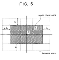
- the panning range of the detected dynamic image A is such as shown by dotted lines in Fig.5, and in case where the detected dynamic image A is panned up, down, right and left by the panning means to e.g. the moved lower left position shown by oblique lines in Fig.6, it is found necessary that the wiper angle ⁇ 2 - ⁇ 1 of invalid image before panning is corrected for the processing to an angle ⁇ 1 + ⁇ 2 .
- the controlling means takes into account not only the drive angle of the driving means but also the pan angle from the panning means in which comparison and determination are made between the predetermined image pickup angle range corrected from the above noted predetermined image pickup angle range ⁇ 1 ⁇ ⁇ 2 according to the pan angle and the drive angle of the driving means, thereby changing the dynamic image A over to the dynamic image A'.
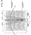
- the scanning lines of an image detected by the image detecting means is preset in the direction substantially perpendicular to the moving (cleaning) direction of the wiper as shown in Fig.9.
- image processing means which has taken in the detected image from the image detection means determines the scanning lines in the masking range for the wiper on the basis of the drive angle of the driving means, in a range which crosses the detected image of the wiper in scanning lines forming the detected image.
- the image processing means masks only the scanning lines in the masking range and provides them as blank data output and provides as an output the detected image with respect to other scanning lines as it is.
- the portion of the scanning lines not crossing the image of the wiper is provided as an output while only the portion of the scanning lines crossing the same is masked and then provided as an output.
- the image processing means instead of the above masking operation, may substitute update static detected image in a valid portion of scanning lines not including the wiper image for the image of the scanning lines in range to be masked. Therefore, only the image of the scanning lines in the masked range is transplanted with static image data for the corresponding scanning lines among an update detected image not including the wiper image.
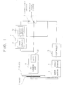
- Fig.1 is a block diagram illustrating the arrangement of one embodiment of a distance measuring equipment according to the present invention, in which a non-reflecting protective glass 1 forms a front window (or a rear window under some circumstances) of a car (not shown), a wiper 2 is provided outside the protective glass 1 to clean up raindrops or dust which adheres to the protective glass 1, a wiper motor 3 is connected to the wiper 2 and serves as means for driving the wiper 2, and an angle sensor 4 is provided for detecting a drive angle of the wiper motor 3.
- a controller 5 is connected to the angle sensor 4 and serves as change-over controlling means to generate a control signal on the basis of the output signal of the angle sensor 4.
- a TV camera unit 6 is provided to detect an image in front of the wiper 2 and includes an A/D (Analog/Digital) converter which converts the detected image into digital data.
- An image storage 7 which includes an image memory 71 and an output image memory 72 is connected to the TV camera unit 6 and serves as means for updating and storing (hereinafter abbreviated as updating-storing) the output data of the TV camera unit 6.
- a change-over switch 8 is connected to the TV camera unit 6 and the image storage 7, and changes the image storage 7 over to the TV camera unit 6. The image storage 7 and the change-over switch 8 are under control of the controller 5.
- the TV camera unit 6 detects an image A (Fig.2) in front of the wiper 2, converts it into digital data at the A/D converter 61 included therein, and continuously delivers the data to the image memory 71 of the image storage 7 as well as the change-over switch 8. At this time, storing the image data from the TV camera unit 6, the image memory 71 is updated by the latest image data.
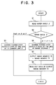
- the wiper 2 is being driven by the wiper motor 3 the drive angle ⁇ of which is detected by the angle sensor 4 and is read to the controller 5, as shown at Step S1 in Fig.3.
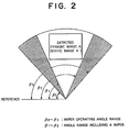
- the controller 5 determines whether or not the drive angle ⁇ resides within a predetermined image pickup angle range ⁇ 1 ⁇ ⁇ 2 shown in Fig.2 of the TV camera unit 6, as shown at Step S2.
- the controller 5 makes the change-over switch 8 change over to the side of the TV camera unit 6 to provide as an output the detected image data, as shown at Step S3.
- the drive angle ⁇ of the wiper 2 resides in the angle range ( ⁇ 1 ⁇ ⁇ ⁇ ⁇ 2 ) other than the oblique line portion in Fig.2, the detected image A is disturbed by the wiper 2 so that it can not be used as it is.
- the angle range ⁇ 1 ⁇ ⁇ 2 can be preset in the controller 5 so as to correspond with the detected image A as a reference.
- the controller 5 makes the change-over switch 8 change over to the side of the image storage 7, as shown at Step S4.
- the controller 5 makes the update image data which is always updated and stored at the image memory 71 of the image storage 7 transfer to the output image memory 72 as shown at Step S5, and makes the data of the output image memory 72 provide as an output through the change-over switch 8 as shown at Step S6.
- the wiper 2 when the wiper 2 resides outside the angle ran ge ⁇ 1 ⁇ ⁇ 2 , the detected image A from the TV camera unit 6 is directly provided as dynamic image data output without change, and when the wiper 2 resides inside the pickup angle range ⁇ 1 ⁇ ⁇ 2 , the update image A' which has been stored while updated at the image memory 71 is sequentially transferred as a static image to the output image memory 72 for a time interval the wiper 2 takes to pass through the angle range ⁇ 1 ⁇ ⁇ 2 . Then, the static image data of the output image memory 72 is read out and provided as an output through the change-over switch 8.
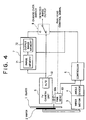
- Fig.4 is a block diagram illustrating the arrangement of another embodiment of an image detection system according to the present invention for the purpose of chasing an object in front of the car by using an image taken by the TV camera unit 6.
- the TV camera unit 6 is mounted on a pan head 60 which serves as panning means for panning the TV camera unit 6 in the up/down and right/left directions and provides as an output an angle signal in the respective directions at the time of panning.
- the controller 5 serving as change-over controlling means generates a control signal for the image storage 7 and the change-over switch 8 by comparing a predetermined image pickup angle range as shown in Fig.2 of the TV camera unit 6 corrected with the pan angle provided from the pan head 60 with the angle of the wiper 2 detected by the angle sensor 4.
- a control signal shown by dotted line in Fig. 4 is provided for the pan head 60 when a control unit (not shown) finds it necessary to pan the TV camera unit 6 as a result of processing image data from the change-over switch 8, and that other elements correspond with the elements shown by the same reference numerals in Fig.1.
- a pickup image A shown by oblique lines, corresponding to the detected dynamic image A in Fig.2 can move within an area shown by dotted line.
- the pan head 60 always provides as an output for the controller 5, by means of a potentiometer or a rotary encoder included therein, the angles of ⁇ ( ⁇ ⁇ ⁇ 1 ) and ⁇ ( ⁇ ⁇ ⁇ 1 ) respectively in the up/down and right/left directions at the the time of panning. It is to be noted that such an angle detection may be carried out by various known techniques.
- the TV camera unit 6 on the pan head 60 takes an image A (see Fig.2) in front of the wiper 2, converts it into digital data at the A/D converter 61, and continuously delivers the data to the image memory 71 of the image storage 7 and the change-over switch 8.
- the image storage 71 is continuously updated by the latest image data. In this state, the data of the image memory 71 has not yet been transferred to the output image memory 72.
- the wiper 2 is being driven by the wiper motor 3 the drive angle ⁇ of which is detected by the angle sensor 4 and is provided for the controller 5, shown at Step S11 in the flow chart of the controller 5 in Fig.7.
- controller 5 is given with an up/down angle ⁇ and a right/left angle ⁇ which are the pan angles of the TV camera unit 6, as shown at Step S12.
- the controller 5 recognizes the pickup direction of the TV camera unit 6 and correspondingly converts the predetermined angle range ⁇ 1 ⁇ ⁇ 2 of the detected dynamic image A shown by oblique lines in Fig.5 into an angle ⁇ 1 commencing the interference with the wiper 2 and an angle ⁇ 2 , terminating the interference of the pickup area A as shown in Fig.6, as follows at Step S13:
- the wiper image gets into the pickup area.
- the controller 5 which has thus calculated the corrected angle range k 1 ⁇ k 2 determines whether or not the drive angle ⁇ from the angle sensor 4 resides within the corrected angle range k 1 ⁇ k 2 of the TV camera unit 6, as shown at Step S14.
- the controller 5 makes the change-over switch 8 change over to the side of the TV camera unit 6 to provide as an output the detected image data without changes, as shown at Step S15.
- the controller 5 makes the change-over switch 8 change over to the side of the image storage 7, as shown at Step S16.
- the controller 5 makes the update image data which is always updated and stored at the image memory 71 of the image storage 7 transfer to the output image memory 72, as shown at Step S17, and makes the data of the static image A' of the output image memory 72 provide as an output through the change-over switch 8, as shown at Step S18.
- the wiper 2 when the wiper 2 resides outside the predetermined image pickup angle range k 1 ⁇ k 2 corrected according to the pan angle of the TV camera unit 6, the detected dynamic image A is directly provided as a dynamic image data output without changes.
- the update static image A' which has been stored while updated at the image memory 71 is sequentially transferred as static image data to the output image memory 72 for a time interval the wiper 2 takes to pass through the pickup angle k 1 ⁇ k 2 . Then, the data of the output image memory 72 are read out therefrom and provided as outputs through the change-over switch 8.
- an image processing circuit 50 is connected to the TV camera unit 6 and the angle sensor 4 and serves as image processing means which determines the range of scanning lines to be mashed with an angle signal from the angle sensor 4 and masks the portion of scanning lines in the masked range with respect to an image signal obtained from the TV camera unit 6.
- the image processing circuit 50 is formed of a horizontal synchronizing detection circuit 51 for detecting a horizontal synchronizing signal in the image signal from the TV camera unit 6, a scanning line counter 52 for counting the scanning line number of the detected image signal based on the horizontal synchronizing signal detected at the horizontal synchronizing detection circuit 51, an A/D converter 53 for converting pixel signals into the corresponding digital signals between adjacent scanning lines, a buffer memory 54 for storing the output data from the A/D converter 53, and CPU 55 responsive to the scanning line number from the counter 52 and the wiper angle ⁇ from the angle sensor 4 to control the A/D converter 53 and the buffer memory 54. It is to be noted that other elements correspond with the elements shown by the same reference numerals in Figs.1 and 4.
- the TV camera unit 6 detects an image A of an object (see Fig.8) in front of the wiper 2 and continuously delivers the image signal to the image processing circuit 50, as shown at Step S21 in the flow chart of the image processing circuit 50 in Fig.11.
- the wiper 2 is being electrically driven by the wiper motor 3, and a signal indicating a drive angle ⁇ of the wiper motor 3 is detected by the angle sensor 4 interlocked with the wiper motor 3 and is then provided for the image processing circuit 50, as shown at Step S22.
- the position of the camera is preset such that the direction of scanning lines of the TV camera unit 6 be perpendicular to the direction of the moving (cleaning) of the wiper 2, as shown by oblique lines in Fig.9.
- the image of the wiper 2 during the cleaning operation is detected by the TV camera unit 6. If the wiper image is positioned at such a position as shown by oblique lines in Fig.9 and it is assumed that the number of invalid scanning lines which the image of the wiper crosses and forms an image signal be n, the CPU 65 of the image processing circuit 50 calculates scanning line numbers j+1 and j+n in the scanning line range on the basis of the drive angle ⁇ of the wiper 2 detected by the angle sensor 4, as shown at Step S23.
- the drive angle at the time when the wiper 2 passes through the image pickup area A shown by a dot-dash line in Fig.9 is predetermined from the mutual positional relationship of the wiper 2 and the TV camera unit 6 so that where in the image taken by the TV camera unit 6 the image of the wiper 2 intrudes into is to be found from the drive angle ⁇ from the angle sensor 4.
- the position of the scanning lines of the image of the wiper 2 resides between the distances l 1 and l 2 .
- the horizontal synchronizing detection circuit 51 of the image processing circuit 50 detects a horizontal synchronizing signal from the detected image signal of the TV camera unit 6, as shown at Step S24.
- a row of blank data corresponding to the pixels of the scanning line is stored at the buffer memory 54, as shown at Step S26.
- the blank data may be "1” if "0" data are detected for actual wiper images. Other various blank data may also be used if predetermined.
- the CPU 55 sequentially reads the data row for each scanning line out of the buffer memory 54, as shown at Step S29, and provides as image data output for one screen after the masking operation, while the wiper portion gives no rise to processing error because of the blank data disregarded for the following data processing.
- the range of the scanning lines 1 ⁇ j+1 and j+n ⁇ 525 is provided as valid image region where no image of the wiper 2 is included.
- the CPU 55 makes each of the pixel data row for each of the scanning lines after the A/D conversion which have been stored as data in the buffer memory 64 store in the frame memory 56 for one frame of the screen in the case where the count a is such that a ⁇ j+1 or j+n ⁇ a, as shown at Step S30. Namely, the pixel data for each of the scanning lines stored in the frame memory 66 are update non-masked data.
- the CPU 55 reads the pixel data row of the scanning lines corresponding to the count of the scanning line counter 52 out of the frame memory 56 in the case where the count a is such that j+1 ⁇ a ⁇ j+n, as shown at Step S31.
- the pixel data row as read out is again stored in the buffer memory 54, as shown at Step S32.
- the data of the buffer memory 54 are provided as outputs as aforementioned, as shown at Step S29, thereby transplanting the data just before masked into the scanning line portion to be masked.
- the image of the wiper 2 intruding into the detected image is masked and blank-displayed, or substituted by image data just before masked, whereby a portion displaying no wiper, i.e. non-masked portion is provided as an output data out of the buffer memory 64 because of being valid.
Description
- The present invention relates to an image detection system for a car, and in particular to a system for detecting and processing an image of a TV camera mounted on a car.
- Heretofore, a system has been researched and developed in which a TV camera is mounted on a car as image detection means in order to find out obstacles on a forward or backward road of the car whereby an alarm is given to a driver, or a brake or a steering gear is automatically operated.
- In this system, the TV camera can be mounted outside a car on one hand or inside a car on the other hand.
- In the former case, it is disadvantageous in that raindrops in case of rain etc. or dust adheres to the surface of the lens of the TV camera, thereby disturbing a clear image.
- A system for removing raindrops or dust which thus adheres to the surface of the lens of the TV camera is disclosed in Japanese Utility Model Application Laid-open JP-U-5925528. However, this system is disadvantageous in that the lens of the TV camera should be rotated every time one desires to clean up raindrops or dust on the lens, which consumes time and disables an image taken meanwhile to be used.
- Moreover, in the latter case where the TV camera is mounted outside a car, the TV camera per se is exposed to raindrops or dust so that the function thereof is easily deteriorated, resulting in a short life.
- Therefore, the TV camera mounted inside a car is preferable to the one mounted outside a car.
- However, it is also disadvantageous in that the image of a wiper for removing raindrops or dust intrudes into images detected by the TV camera. Therefore, if image processing is carried out as it is, a screen including the wiper image has no context with the adjacent screens so that the wiper image is to be detected as the nearest obstacle.
- Thus, useless image processing with such an unavailable image, is carried out so as to cause the car erroneously to run in an automatic chase for an object.
- In view of these problems, JP-A-1 273 114 suggests an image detection system which suppresses the wiper image.
- Accordingly, it is an object of the present invention to provide an improved image detection system for a car, with a TV camera mounted inside a car, which always makes clear images available under no influence of a wiper image.
- According to the present invention, image detecting means continuously detects an image in front of a wiper and provides it for image updating-storing means and an change-over means in the form of data.
- While the wiper is driven by driving means, when the drive angle of the driving means is detected by drive angle detecting means and provided for controlling means, the controlling means determines whether or not the detected drive angle of the wiper resides within a predetermined image pickup angle of the image detecting means and controls the change-over means to the side of the image updating-storing means. At the same time, the controlling means makes the updating-storing means provide the image as data output.
- Thus, as shown in Fig.2, when the wiper resides outside the predetermined image pickup angle β1 ∼ β2, the dynamic image A detected by the image detecting means is directly provided as an output without change while when the wiper resides within the predetermined image pickup angle β1 ∼ β2, the dynamic image is unavailable so that an update image A having been updated and stored in the image updating-storing means from the image detecting means so far is provided as an static image output.
- Accordingly, a clear image is detected under no influence of the wiper image even in rainy weather etc. and useless processing time can be removed in image processing and recognition etc. which are carried out for the provided image data.
- According to another aspect of the present invention, normally, for the purpose of more accurate recognition (object chase) of visual information around the car with reference to the region of the detected image A as shown in Fig.2, the image detecting means is panned in the up, down, right and left directions within a certain fixed range by panning means to obtain a desired image.
- Since the image detecting means is thus panned up, down, right and left by the panning means, the detected dynamic image A in Fig.2 is relatively moved according to the panning of the image detecting means even though the moving range of the wiper is fixed.
- Therefore, if the panning range of the detected dynamic image A is such as shown by dotted lines in Fig.5, and in case where the detected dynamic image A is panned up, down, right and left by the panning means to e.g. the moved lower left position shown by oblique lines in Fig.6, it is found necessary that the wiper angle β2 - β1 of invalid image before panning is corrected for the processing to an angle γ1 + γ2.
- Thereupon, the controlling means takes into account not only the drive angle of the driving means but also the pan angle from the panning means in which comparison and determination are made between the predetermined image pickup angle range corrected from the above noted predetermined image pickup angle range β1 ∼ β2 according to the pan angle and the drive angle of the driving means, thereby changing the dynamic image A over to the dynamic image A'.
- Thus, even if the image detecting means is panned up, down, left and right anyhow, a clear image is obtained under no infulentce of the wiper image and whatever panning position the image detecting means is controlled to chase an object
- According to a further aspect of the present invention, the scanning lines of an image detected by the image detecting means is preset in the direction substantially perpendicular to the moving (cleaning) direction of the wiper as shown in Fig.9.
- Hereupon, since the wiper has a certain width as shown by oblique lines in Fig.9, image processing means which has taken in the detected image from the image detection means determines the scanning lines in the masking range for the wiper on the basis of the drive angle of the driving means, in a range which crosses the detected image of the wiper in scanning lines forming the detected image.
- Then, the image processing means masks only the scanning lines in the masking range and provides them as blank data output and provides as an output the detected image with respect to other scanning lines as it is.
- Hereby, when the wiper image intrudes into the image processing means in the form of the detected image, the portion of the scanning lines not crossing the image of the wiper is provided as an output while only the portion of the scanning lines crossing the same is masked and then provided as an output.
- Also, according to the present invention, the image processing means, instead of the above masking operation, may substitute update static detected image in a valid portion of scanning lines not including the wiper image for the image of the scanning lines in range to be masked. Therefore, only the image of the scanning lines in the masked range is transplanted with static image data for the corresponding scanning lines among an update detected image not including the wiper image.
- Thus, the deterioration of the quality of the image data due to the wiper image in rainy weather etc. is kept to an extremely limited, minimum area in which the wiper can exist on the detected image.
- The present invention will now be more apparent to those skilled in the art from the attached drawings in which;
- Fig.1 is a block diagram showing a system arrangement of one embodiment of an image detection system for a car according to the present invention;
- Fig.2 is a principle graph for the illustration of the relationship between an operating angle of a wiper and a detected image in the present invention;
- Fig.3 is a flow chart showing the processing algorithm of a controller used in Fig.1;
- Fig.4 is a block diagram of a system arrangement of another embodiment of an image detection system for a car according to the present invention;
- Fig.5 is a graph for the illustration of a movable area of an image pickup area of a TV camera unit at the time of panning in the embodiment in Fig.4;
- Fig.6 is a principle graph showing the relationship between an operating angle of a wiper and a movable image pickup area when the TV camera unit is panned in the embodiment in Fig.4;
- Fig.7 is a flow chart showing the processing algorithm of a controller used in the embodiment in Fig. 4;
- Fig. 8 is a block diagram showing a system arrangement of a further embodiment of an image detection system for a car according to the present invention;
- Fig. 9 is a graph for the illustration of the relationship between the image of a wiper and scanning lines of a TV camera unit in the embodiment in Fig.8;
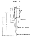
- Fig.10 is a principle graph for the illustration of of a method for determining a scanning line range to be masked in the embodiment in Fig.8; and,
- Fig.11 is a flow chart showing the masking algorithm of the embodiment in Fig. 8.
- Fig.1 is a block diagram illustrating the arrangement of one embodiment of a distance measuring equipment according to the present invention, in which a non-reflecting
protective glass 1 forms a front window (or a rear window under some circumstances) of a car (not shown), awiper 2 is provided outside theprotective glass 1 to clean up raindrops or dust which adheres to theprotective glass 1, awiper motor 3 is connected to thewiper 2 and serves as means for driving thewiper 2, and anangle sensor 4 is provided for detecting a drive angle of thewiper motor 3. - A
controller 5 is connected to theangle sensor 4 and serves as change-over controlling means to generate a control signal on the basis of the output signal of theangle sensor 4. ATV camera unit 6 is provided to detect an image in front of thewiper 2 and includes an A/D (Analog/Digital) converter which converts the detected image into digital data. Animage storage 7 which includes animage memory 71 and anoutput image memory 72 is connected to theTV camera unit 6 and serves as means for updating and storing (hereinafter abbreviated as updating-storing) the output data of theTV camera unit 6. A change-over switch 8 is connected to theTV camera unit 6 and theimage storage 7, and changes theimage storage 7 over to theTV camera unit 6. Theimage storage 7 and the change-over switch 8 are under control of thecontroller 5. - Next, the operation of the above embodiment will be described with reference to Fig.2 and Fig.3 showing the processing algorithm of the
controller 5. - The
TV camera unit 6 detects an image A (Fig.2) in front of thewiper 2, converts it into digital data at the A/D converter 61 included therein, and continuously delivers the data to theimage memory 71 of theimage storage 7 as well as the change-overswitch 8. At this time, storing the image data from theTV camera unit 6, theimage memory 71 is updated by the latest image data. - In this state, the data of the
image memory 71 has not yet been transferred to theoutput image memory 72. - In the meantime, the
wiper 2 is being driven by thewiper motor 3 the drive angle β of which is detected by theangle sensor 4 and is read to thecontroller 5, as shown at Step S1 in Fig.3. - The
controller 5 then determines whether or not the drive angle β resides within a predetermined image pickup angle range β1 ∼ β2 shown in Fig.2 of theTV camera unit 6, as shown at Step S2. - As a result of this determination, if it is found that the drive angle β of the
wiper 2 resides in the angle range (β0 < β ≦ β1 or β2 < β ≦ β3) shown by oblique lines in Fig.2, which means that the detected image A is not disturbed by thewiper 2, thecontroller 5 makes the change-overswitch 8 change over to the side of theTV camera unit 6 to provide as an output the detected image data, as shown at Step S3. - If it is found that the drive angle β of the
wiper 2 resides in the angle range (β1 < β < β2) other than the oblique line portion in Fig.2, the detected image A is disturbed by thewiper 2 so that it can not be used as it is. It should be noted that the angle range β1 ∼ β2 can be preset in thecontroller 5 so as to correspond with the detected image A as a reference. - Therefore, the
controller 5 makes the change-over switch 8 change over to the side of theimage storage 7, as shown at Step S4. - Then, the
controller 5 makes the update image data which is always updated and stored at theimage memory 71 of theimage storage 7 transfer to theoutput image memory 72 as shown at Step S5, and makes the data of theoutput image memory 72 provide as an output through the change-overswitch 8 as shown at Step S6. - Thus, when the
wiper 2 resides outside the angle ran ge β1 ∼ β2, the detected image A from theTV camera unit 6 is directly provided as dynamic image data output without change, and when thewiper 2 resides inside the pickup angle range β1 ∼ β2, the update image A' which has been stored while updated at theimage memory 71 is sequentially transferred as a static image to theoutput image memory 72 for a time interval thewiper 2 takes to pass through the angle range β1 ∼ β2. Then, the static image data of theoutput image memory 72 is read out and provided as an output through the change-over switch 8. - Fig.4 is a block diagram illustrating the arrangement of another embodiment of an image detection system according to the present invention for the purpose of chasing an object in front of the car by using an image taken by the
TV camera unit 6. - For this purpose, the
TV camera unit 6 is mounted on apan head 60 which serves as panning means for panning theTV camera unit 6 in the up/down and right/left directions and provides as an output an angle signal in the respective directions at the time of panning. So, thecontroller 5 serving as change-over controlling means generates a control signal for theimage storage 7 and the change-overswitch 8 by comparing a predetermined image pickup angle range as shown in Fig.2 of theTV camera unit 6 corrected with the pan angle provided from thepan head 60 with the angle of thewiper 2 detected by theangle sensor 4. It is to be noted that a control signal shown by dotted line in Fig. 4 is provided for thepan head 60 when a control unit (not shown) finds it necessary to pan theTV camera unit 6 as a result of processing image data from the change-overswitch 8, and that other elements correspond with the elements shown by the same reference numerals in Fig.1. - Next, the operation of the above embodiment in Fig.4 will be described with reference to Fig.2 and Figs.5 to 7.
- It is now assumed that the
TV camera unit 6 supported by thepan head 60 can pan to the maximum angle ± α1 in the up/down pickup directions and the maximum angle ± θ1 in the right/left pickup directions with reference to the origin 0 as shown in Fig.5. Namely, a pickup image A, shown by oblique lines, corresponding to the detected dynamic image A in Fig.2 can move within an area shown by dotted line. - At this time, the
pan head 60 always provides as an output for thecontroller 5, by means of a potentiometer or a rotary encoder included therein, the angles of α (α ≦ α1) and θ (θ ≦ θ1) respectively in the up/down and right/left directions at the the time of panning. It is to be noted that such an angle detection may be carried out by various known techniques. - The
TV camera unit 6 on thepan head 60 takes an image A (see Fig.2) in front of thewiper 2, converts it into digital data at the A/D converter 61, and continuously delivers the data to theimage memory 71 of theimage storage 7 and the change-overswitch 8. - At this time, storing the image data from the
TV camera unit 6, theimage storage 71 is continuously updated by the latest image data. In this state, the data of theimage memory 71 has not yet been transferred to theoutput image memory 72. - In the meantime, the
wiper 2 is being driven by thewiper motor 3 the drive angle β of which is detected by theangle sensor 4 and is provided for thecontroller 5, shown at Step S11 in the flow chart of thecontroller 5 in Fig.7. - Also, the
controller 5 is given with an up/down angle α and a right/left angle θ which are the pan angles of theTV camera unit 6, as shown at Step S12. - From these angles, the
controller 5 recognizes the pickup direction of theTV camera unit 6 and correspondingly converts the predetermined angle range β1 ∼ β2 of the detected dynamic image A shown by oblique lines in Fig.5 into an angle γ1 commencing the interference with thewiper 2 and an angle γ2, terminating the interference of the pickup area A as shown in Fig.6, as follows at Step S13: - At first, assuming that a distance from the panning
axis 60a of thepan head 60 to the cleaning face of the wiper be δ, the size of the pickup area A be L1 long by L2 wide, and a distance between the rotating axsis of thewiper 2 and the origin 0 of the pickup area A be H, the angles γ1, γ 2 are given by the following equation: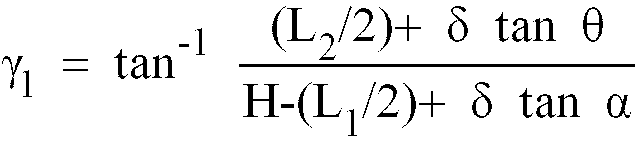

- Therefore, according to the up/down angle α and the right/left angle θ of the pan angle, pickup angles k1, k2 are corrected from the reference angle range β1 ∼ β2 (see Fig.2) as follows:


- Namely, in the angle range k1 ∼ k2, the wiper image gets into the pickup area.
- It is to be noted that the size L1, L2 of the pickup area A can be predetermined by the aforementioned distance δ and the pickup angle of the
TV camera unit 6. - The
controller 5 which has thus calculated the corrected angle range k1 ∼k2 determines whether or not the drive angle β from theangle sensor 4 resides within the corrected angle range k1∼k2 of theTV camera unit 6, as shown at Step S14. - As a result of this determination, if the drive angle β of the
wiper 2 resides in the angle range (β ≦ k1 or k2 ≦ β) shown by oblique lines in Fig.6, which means that the detected dynamic image A is not disturbed by thewiper 2, thecontroller 5 makes the change-overswitch 8 change over to the side of theTV camera unit 6 to provide as an output the detected image data without changes, as shown at Step S15. - On the other hand, if the drive angle β of the
wiper 2 resides in the angle range (k1 < β < k2) within the oblique line portion in Fig.6, the detected image A is disturbed by thewiper 2 so that it can not be used as it is. - Therefore, the
controller 5 makes the change-overswitch 8 change over to the side of theimage storage 7, as shown at Step S16. - Then, the
controller 5 makes the update image data which is always updated and stored at theimage memory 71 of theimage storage 7 transfer to theoutput image memory 72, as shown at Step S17, and makes the data of the static image A' of theoutput image memory 72 provide as an output through the change-overswitch 8, as shown at Step S18. - Thus, when the
wiper 2 resides outside the predetermined image pickup angle range k1∼k2 corrected according to the pan angle of theTV camera unit 6, the detected dynamic image A is directly provided as a dynamic image data output without changes. However, when thewiper 2 resides within the pickup angle range k1∼k2, the update static image A' which has been stored while updated at theimage memory 71 is sequentially transferred as static image data to theoutput image memory 72 for a time interval thewiper 2 takes to pass through the pickup angle k1∼k2. Then, the data of theoutput image memory 72 are read out therefrom and provided as outputs through the change-overswitch 8. - Fig.8 is a block diagram illustrating the arrangement of a further embodiment of an image detection system according to the present invention for the purpose of substituting predetermined data for the image of the wiper during moving.
- For this purpose, an
image processing circuit 50 is connected to theTV camera unit 6 and theangle sensor 4 and serves as image processing means which determines the range of scanning lines to be mashed with an angle signal from theangle sensor 4 and masks the portion of scanning lines in the masked range with respect to an image signal obtained from theTV camera unit 6. - The
image processing circuit 50 is formed of a horizontalsynchronizing detection circuit 51 for detecting a horizontal synchronizing signal in the image signal from theTV camera unit 6, ascanning line counter 52 for counting the scanning line number of the detected image signal based on the horizontal synchronizing signal detected at the horizontalsynchronizing detection circuit 51, an A/D converter 53 for converting pixel signals into the corresponding digital signals between adjacent scanning lines, abuffer memory 54 for storing the output data from the A/D converter 53, andCPU 55 responsive to the scanning line number from thecounter 52 and the wiper angle θ from theangle sensor 4 to control the A/D converter 53 and thebuffer memory 54. It is to be noted that other elements correspond with the elements shown by the same reference numerals in Figs.1 and 4. - Next, the operation of the above embodiment in Fig.8 will be described with reference to Figs.9-11.
- The
TV camera unit 6 detects an image A of an object (see Fig.8) in front of thewiper 2 and continuously delivers the image signal to theimage processing circuit 50, as shown at Step S21 in the flow chart of theimage processing circuit 50 in Fig.11. - On the other hand, the
wiper 2 is being electrically driven by thewiper motor 3, and a signal indicating a drive angle θ of thewiper motor 3 is detected by theangle sensor 4 interlocked with thewiper motor 3 and is then provided for theimage processing circuit 50, as shown at Step S22. - It is to be noted that the position of the camera is preset such that the direction of scanning lines of the
TV camera unit 6 be perpendicular to the direction of the moving (cleaning) of thewiper 2, as shown by oblique lines in Fig.9. - Then, the image of the
wiper 2 during the cleaning operation is detected by theTV camera unit 6. If the wiper image is positioned at such a position as shown by oblique lines in Fig.9 and it is assumed that the number of invalid scanning lines which the image of the wiper crosses and forms an image signal be n, the CPU 65 of theimage processing circuit 50 calculates scanning line numbers j+1 and j+n in the scanning line range on the basis of the drive angle θ of thewiper 2 detected by theangle sensor 4, as shown at Step S23. It is to be noted that the drive angle at the time when thewiper 2 passes through the image pickup area A shown by a dot-dash line in Fig.9 is predetermined from the mutual positional relationship of thewiper 2 and theTV camera unit 6 so that where in the image taken by theTV camera unit 6 the image of thewiper 2 intrudes into is to be found from the drive angle θ from theangle sensor 4. - Hereinafter, the method of calculating the above-noted scanning line numbers j+1 and j+n from the drive angle of the
wiper 2 will be described with reference to Fig.10. - In Fig.10, assuming that the size of the pickup area be L1 long and L2 wide and the distance between the rotational center of the
wiper 2 and the origin 0 of the pickup area A be H, and the horizontal distances ℓ1, ℓ2 from the origin 0 in the range of the scanning lines j+1∼j+n (shown by oblique lines) which are thought to be crossing thewiper 2 are given by the repective equations:

- Namely, if the wide distance L2 of the pickup area is formed by N scanning lines, the position of the scanning lines of the image of the
wiper 2 resides between the distances ℓ1 and ℓ2. - Accordingly, the scanning line numbers j+1 and j+n corresponding to the distance range ℓ1 ∼ ℓ2 are given by the following equations because L2 corresponds to N, ℓ1 corresponds to j+1, and ℓ2 corresponds to j+n, respectively:


- It is to be noted that in practice a margin may be given to the above j+1 and j+n, taking into account that the
wiper 2 has an arm or blade as can be unintentionally moved due to its transformation. - Then, the following masking operation will be carried out with respect to the j+1st scanning line∼ j+nth scanning line to be masked as noted-above among all of the scanning lines forming the image signal provided as an output from the TV camera unit 6:
- First of all, the horizontal
synchronizing detection circuit 51 of theimage processing circuit 50 detects a horizontal synchronizing signal from the detected image signal of theTV camera unit 6, as shown at Step S24. - Then, the scanning line counter 52 counts the scanning lines from the number of 1 to the maximum N included in the horizontal sysnchronizing signal as detected and the count is provided for the
CPU 55, which carries out the following processing in the respective cases of the count a being such that j+1 ≦ a ≦ j+n, a<j+1, or j+n <a, as shown at Step S25. - At first, in the case where the count a is such that j+1≦ a ≦ j+n, a row of blank data corresponding to the pixels of the scanning line is stored at the
buffer memory 54, as shown at Step S26. It is to be noted that the blank data may be "1" if "0" data are detected for actual wiper images. Other various blank data may also be used if predetermined. - In the case where the count a is such that a<j+1 or j+n < a, the
CPU 55 makes the A/D converter 53 convert the pixel signals into the corresponding digital data in the scanning lines, as shown at Step S27 and stores the data row into thebuffer memory 54 in correspondence with the scanning lines, as shown at Step S28. - The
CPU 55 sequentially reads the data row for each scanning line out of thebuffer memory 54, as shown at Step S29, and provides as image data output for one screen after the masking operation, while the wiper portion gives no rise to processing error because of the blank data disregarded for the following data processing. - It is to be noted that the scanning lines forming the image shown in Fig.9 are formed of 525 scanning lines (=N scanning lines) according to the NTSC system. In this case, the range of the
scanning lines 1∼j+1 and j+n ∼525 is provided as valid image region where no image of thewiper 2 is included. - Next, the method of the present invention wherein instead of the scanning line portion as masked in the above masking operation being given blank data, this portion is substituted by data before masked will be described. It is to be noted that the flow of the processing of this alternative is shown by dotted lines.
- The
CPU 55 makes each of the pixel data row for each of the scanning lines after the A/D conversion which have been stored as data in thebuffer memory 64 store in theframe memory 56 for one frame of the screen in the case where the count a is such that a<j+1 or j+n< a, as shown at Step S30. Namely, the pixel data for each of the scanning lines stored in the frame memory 66 are update non-masked data. - Therefore, the
CPU 55 reads the pixel data row of the scanning lines corresponding to the count of thescanning line counter 52 out of theframe memory 56 in the case where the count a is such that j+1 ≦ a ≦ j+n, as shown at Step S31. - Then, the pixel data row as read out is again stored in the
buffer memory 54, as shown at Step S32. - Thereafter, the data of the
buffer memory 54 are provided as outputs as aforementioned, as shown at Step S29, thereby transplanting the data just before masked into the scanning line portion to be masked. - Thus, the image of the
wiper 2 intruding into the detected image is masked and blank-displayed, or substituted by image data just before masked, whereby a portion displaying no wiper, i.e. non-masked portion is provided as an output data out of thebuffer memory 64 because of being valid. - While a number of alternatives and modifications have been discussed above, it will be appreciated that the invention encompasses all forms and variations within the scope of the appended claims.
Claims (6)
- An image detection system for a car, having means (3) for driving a wiper (2) and means (6) for detecting an image in front of said wiper (2) from the inside of the car and providing it as data output, characterized by comprising:means (4) for detecting a drive angle of said driving means (3);means for updating-storing the image data output from said image detecting means (6);means (8) for switching over between the connection of the output of the system with the output of the image detecting means (6) and the connection of the output of the system with the output of the updating-storing means (7); andmeans (5) for controlling said switching means (8) in such a way that the output of the system is connected with the output of the updating-storing means (7) only in case said drive angle resides in a predetermined image pickup angle range of said image detecting means (6), the output of the system thus providing static image data from said updating-storing means (7).
- An image detection system as claimed in claim 1, characterized by means (60) for panning said image detecting means (6) up, down, right and left within a predetermined range and for providing, as an output, the pan angle.
- An image detecting system as claimed in claim 1 or 2, characterized in that said updating-storing means (7) includes an image memory (71) continouosly updated by the data output of said image detecting means (6) and an output image memory (72) connected to one side of said switching means (8) and storing and providing as outputs the update image data of said image memory (71) when said change-over means (8) is changed over to the side of said image storage (7).
- An image detecting system as claimed in claims 1 or 2, characterized in that said controlling means (5) controls said switching means (8) in such a way that the output of the system is connected with the output of the image detecting means (6) only in case said drive angle resides outside the predetermined image pickup angle range of said image detecting means (6), the output of the system thus providing dynamic image data from said image detecting means (6).
- An image detection system as claimed in any one of the claims 1-4, characterized by further comprising: Image processing means (50) for calculating, from said drive angle, a masking range said wiper (2) crosses in all of the perpendicular scanning lines of the image detected by said image detecting means (8) and for masking only the image of the scanning lines in the masking range and providing, as outputs, blank data or static image data just before masking.
- An image detection system as claimed in claim 5, wherein said image processing means (50) includes a buffer memory (54) continuously updated by the output of said image detecting means (8) for providing as outputs the updated data and a frame memory (56) continuously storing the updated image data of said buffer memory (54) and transferring the data therein corresponding to the masking range into said buffer memory (54) only when said wiper (2) crosses the masking range.
Applications Claiming Priority (6)
| Application Number | Priority Date | Filing Date | Title |
|---|---|---|---|
| JP2262661A JPH0825423B2 (en) | 1990-09-28 | 1990-09-28 | Vehicle image detection device |
| JP2262663A JPH0832509B2 (en) | 1990-09-28 | 1990-09-28 | Vehicle image detection device |
| JP262663/90 | 1990-09-28 | ||
| JP262661/90 | 1990-09-28 | ||
| JP2262662A JPH078041B2 (en) | 1990-09-28 | 1990-09-28 | Vehicle image detection device |
| JP262662/90 | 1990-09-28 |
Publications (3)
| Publication Number | Publication Date |
|---|---|
| EP0477986A2 EP0477986A2 (en) | 1992-04-01 |
| EP0477986A3 EP0477986A3 (en) | 1992-09-23 |
| EP0477986B1 true EP0477986B1 (en) | 1996-11-20 |
Family
ID=27335149
Family Applications (1)
| Application Number | Title | Priority Date | Filing Date |
|---|---|---|---|
| EP91116608A Expired - Lifetime EP0477986B1 (en) | 1990-09-28 | 1991-09-27 | Image detection system for a car |
Country Status (3)
| Country | Link |
|---|---|
| US (1) | US5177606A (en) |
| EP (1) | EP0477986B1 (en) |
| DE (1) | DE69123212T2 (en) |
Cited By (6)
| Publication number | Priority date | Publication date | Assignee | Title |
|---|---|---|---|---|
| US8818042B2 (en) | 2004-04-15 | 2014-08-26 | Magna Electronics Inc. | Driver assistance system for vehicle |
| US8842176B2 (en) | 1996-05-22 | 2014-09-23 | Donnelly Corporation | Automatic vehicle exterior light control |
| US8917169B2 (en) | 1993-02-26 | 2014-12-23 | Magna Electronics Inc. | Vehicular vision system |
| US8993951B2 (en) | 1996-03-25 | 2015-03-31 | Magna Electronics Inc. | Driver assistance system for a vehicle |
| US9171217B2 (en) | 2002-05-03 | 2015-10-27 | Magna Electronics Inc. | Vision system for vehicle |
| US9436880B2 (en) | 1999-08-12 | 2016-09-06 | Magna Electronics Inc. | Vehicle vision system |
Families Citing this family (41)
| Publication number | Priority date | Publication date | Assignee | Title |
|---|---|---|---|---|
| US5729016A (en) * | 1994-04-12 | 1998-03-17 | Hughes Aircraft Company | Low cost night vision system for nonmilitary surface vehicles |
| DE29514364U1 (en) * | 1995-09-07 | 1996-01-18 | Hohe Gmbh & Co Kg | Image acquisition module |
| JP4571246B2 (en) * | 1998-06-26 | 2010-10-27 | 富士フイルム株式会社 | Tv camera housing |
| DE10126492B4 (en) * | 2001-05-31 | 2004-05-19 | Daimlerchrysler Ag | Method for improving the visibility in vehicles |
| US6882287B2 (en) | 2001-07-31 | 2005-04-19 | Donnelly Corporation | Automotive lane change aid |
| US7697027B2 (en) | 2001-07-31 | 2010-04-13 | Donnelly Corporation | Vehicular video system |
| JP2003098424A (en) * | 2001-09-25 | 2003-04-03 | Fujitsu Ten Ltd | Range finder based on image processing |
| JP2006050263A (en) * | 2004-08-04 | 2006-02-16 | Olympus Corp | Image generation method and device |
| US7881496B2 (en) | 2004-09-30 | 2011-02-01 | Donnelly Corporation | Vision system for vehicle |
| US7720580B2 (en) | 2004-12-23 | 2010-05-18 | Donnelly Corporation | Object detection system for vehicle |
| US7196305B2 (en) * | 2005-01-18 | 2007-03-27 | Ford Global Technologies, Llc | Vehicle imaging processing system and method having obstructed image detection |
| US7972045B2 (en) | 2006-08-11 | 2011-07-05 | Donnelly Corporation | Automatic headlamp control system |
| US8017898B2 (en) | 2007-08-17 | 2011-09-13 | Magna Electronics Inc. | Vehicular imaging system in an automatic headlamp control system |
| ES2538827T3 (en) | 2009-09-01 | 2015-06-24 | Magna Mirrors Of America, Inc. | Imaging and display system for a vehicle |
| WO2012075250A1 (en) | 2010-12-01 | 2012-06-07 | Magna Electronics Inc. | System and method of establishing a multi-camera image using pixel remapping |
| US9264672B2 (en) | 2010-12-22 | 2016-02-16 | Magna Mirrors Of America, Inc. | Vision display system for vehicle |
| US9357208B2 (en) | 2011-04-25 | 2016-05-31 | Magna Electronics Inc. | Method and system for dynamically calibrating vehicular cameras |
| US9834153B2 (en) | 2011-04-25 | 2017-12-05 | Magna Electronics Inc. | Method and system for dynamically calibrating vehicular cameras |
| JP5953658B2 (en) * | 2011-05-25 | 2016-07-20 | ソニー株式会社 | ROBOT CONTROL DEVICE, ROBOT DEVICE CONTROL METHOD, COMPUTER PROGRAM, PROGRAM STORAGE MEDIUM, AND ROBOT DEVICE |
| WO2013016409A1 (en) | 2011-07-26 | 2013-01-31 | Magna Electronics Inc. | Vision system for vehicle |
| WO2013019707A1 (en) | 2011-08-01 | 2013-02-07 | Magna Electronics Inc. | Vehicle camera alignment system |
| US20140218535A1 (en) | 2011-09-21 | 2014-08-07 | Magna Electronics Inc. | Vehicle vision system using image data transmission and power supply via a coaxial cable |
| WO2013074604A2 (en) | 2011-11-15 | 2013-05-23 | Magna Electronics, Inc. | Calibration system and method for vehicular surround vision system |
| US10099614B2 (en) | 2011-11-28 | 2018-10-16 | Magna Electronics Inc. | Vision system for vehicle |
| WO2013086249A2 (en) | 2011-12-09 | 2013-06-13 | Magna Electronics, Inc. | Vehicle vision system with customized display |
| US10457209B2 (en) | 2012-02-22 | 2019-10-29 | Magna Electronics Inc. | Vehicle vision system with multi-paned view |
| US9436005B2 (en) | 2012-08-02 | 2016-09-06 | Gentex Corporation | Amplified piezoelectric camera lens cleaner |
| US9380190B2 (en) | 2012-08-06 | 2016-06-28 | Gentex Corporation | Rotating lens apparatus |
| US9723272B2 (en) | 2012-10-05 | 2017-08-01 | Magna Electronics Inc. | Multi-camera image stitching calibration system |
| US10179543B2 (en) | 2013-02-27 | 2019-01-15 | Magna Electronics Inc. | Multi-camera dynamic top view vision system |
| US9508014B2 (en) | 2013-05-06 | 2016-11-29 | Magna Electronics Inc. | Vehicular multi-camera vision system |
| US9205776B2 (en) | 2013-05-21 | 2015-12-08 | Magna Electronics Inc. | Vehicle vision system using kinematic model of vehicle motion |
| US9563951B2 (en) | 2013-05-21 | 2017-02-07 | Magna Electronics Inc. | Vehicle vision system with targetless camera calibration |
| US9916660B2 (en) | 2015-01-16 | 2018-03-13 | Magna Electronics Inc. | Vehicle vision system with calibration algorithm |
| US10946799B2 (en) | 2015-04-21 | 2021-03-16 | Magna Electronics Inc. | Vehicle vision system with overlay calibration |
| US11277558B2 (en) | 2016-02-01 | 2022-03-15 | Magna Electronics Inc. | Vehicle vision system with master-slave camera configuration |
| US11433809B2 (en) | 2016-02-02 | 2022-09-06 | Magna Electronics Inc. | Vehicle vision system with smart camera video output |
| US10935949B2 (en) * | 2016-05-17 | 2021-03-02 | Mitsubishi Electric Corporation | Controller system |
| JP2018043642A (en) * | 2016-09-14 | 2018-03-22 | 株式会社東海理化電機製作所 | Vehicular visual confirmation device |
| CN109435852B (en) * | 2018-11-08 | 2021-11-02 | 湖北工业大学 | Panoramic auxiliary driving system and method for large truck |
| CN115902904B (en) * | 2023-01-06 | 2023-06-30 | 四川三思德科技有限公司 | Image data acquisition method and device based on dynamic identification |
Family Cites Families (4)
| Publication number | Priority date | Publication date | Assignee | Title |
|---|---|---|---|---|
| DE3111728A1 (en) * | 1981-03-25 | 1982-10-07 | Philips Patentverwaltung Gmbh, 2000 Hamburg | "TESTING PROCEDURE FOR WORKPIECES" |
| JPH01273114A (en) * | 1988-04-25 | 1989-11-01 | Mazda Motor Corp | Image processor for moving car |
| US4843463A (en) * | 1988-05-23 | 1989-06-27 | Michetti Joseph A | Land vehicle mounted audio-visual trip recorder |
| US5111289A (en) * | 1990-04-27 | 1992-05-05 | Lucas Gary L | Vehicular mounted surveillance and recording system |
-
1991
- 1991-09-27 US US07/766,068 patent/US5177606A/en not_active Expired - Fee Related
- 1991-09-27 EP EP91116608A patent/EP0477986B1/en not_active Expired - Lifetime
- 1991-09-27 DE DE69123212T patent/DE69123212T2/en not_active Expired - Fee Related
Cited By (10)
| Publication number | Priority date | Publication date | Assignee | Title |
|---|---|---|---|---|
| US8917169B2 (en) | 1993-02-26 | 2014-12-23 | Magna Electronics Inc. | Vehicular vision system |
| US8993951B2 (en) | 1996-03-25 | 2015-03-31 | Magna Electronics Inc. | Driver assistance system for a vehicle |
| US8842176B2 (en) | 1996-05-22 | 2014-09-23 | Donnelly Corporation | Automatic vehicle exterior light control |
| US9436880B2 (en) | 1999-08-12 | 2016-09-06 | Magna Electronics Inc. | Vehicle vision system |
| US9171217B2 (en) | 2002-05-03 | 2015-10-27 | Magna Electronics Inc. | Vision system for vehicle |
| US9555803B2 (en) | 2002-05-03 | 2017-01-31 | Magna Electronics Inc. | Driver assistance system for vehicle |
| US8818042B2 (en) | 2004-04-15 | 2014-08-26 | Magna Electronics Inc. | Driver assistance system for vehicle |
| US9008369B2 (en) | 2004-04-15 | 2015-04-14 | Magna Electronics Inc. | Vision system for vehicle |
| US9191634B2 (en) | 2004-04-15 | 2015-11-17 | Magna Electronics Inc. | Vision system for vehicle |
| US9428192B2 (en) | 2004-04-15 | 2016-08-30 | Magna Electronics Inc. | Vision system for vehicle |
Also Published As
| Publication number | Publication date |
|---|---|
| DE69123212T2 (en) | 1997-04-10 |
| EP0477986A2 (en) | 1992-04-01 |
| DE69123212D1 (en) | 1997-01-02 |
| EP0477986A3 (en) | 1992-09-23 |
| US5177606A (en) | 1993-01-05 |
Similar Documents
| Publication | Publication Date | Title |
|---|---|---|
| EP0477986B1 (en) | Image detection system for a car | |
| US7697055B2 (en) | Camera unit and apparatus for monitoring vehicle periphery | |
| US7557691B2 (en) | Obstacle detector for vehicle | |
| US9272731B2 (en) | Driving-operation assist and recording medium | |
| US7605856B2 (en) | Camera unit and apparatus for monitoring vehicle periphery | |
| US7619668B2 (en) | Abnormality detecting apparatus for imaging apparatus | |
| JP3739693B2 (en) | Image recognition device | |
| JP2002074339A (en) | On-vehicle image pickup unit | |
| JPH04313199A (en) | Distance between cars detector | |
| JP3847547B2 (en) | Vehicle periphery monitoring support device | |
| JP5036891B2 (en) | Camera device and vehicle periphery monitoring device mounted on vehicle | |
| JP2008098858A (en) | Vehicle periphery monitoring device | |
| US20050057651A1 (en) | Apparatus for visually confirming vehicle periphery | |
| JPH04188014A (en) | Apparatus for detecting distance between vehicles | |
| JP2006012191A (en) | Lane marking recognition device for vehicle | |
| JP2002099908A (en) | Detection of approaching vehicle, and image processing device detecting vehicle lane position | |
| JP2006178652A (en) | Vehicle environment recognition system and image processor | |
| JP3882304B2 (en) | Self-driving vehicle position detector | |
| JPH07250268A (en) | Vehicle periphery monitoring device | |
| JP3424386B2 (en) | Vehicle rear monitoring device | |
| JP2001071790A (en) | Vehicular display device | |
| JPH09266572A (en) | Camera for monitoring outside of vehicle | |
| JPH0832509B2 (en) | Vehicle image detection device | |
| JPH078041B2 (en) | Vehicle image detection device | |
| EP0498416B1 (en) | Inter-car distance detecting device |
Legal Events
| Date | Code | Title | Description |
|---|---|---|---|
| PUAI | Public reference made under article 153(3) epc to a published international application that has entered the european phase |
Free format text: ORIGINAL CODE: 0009012 |
|
| AK | Designated contracting states |
Kind code of ref document: A2 Designated state(s): DE FR GB |
|
| PUAL | Search report despatched |
Free format text: ORIGINAL CODE: 0009013 |
|
| AK | Designated contracting states |
Kind code of ref document: A3 Designated state(s): DE FR GB |
|
| 17P | Request for examination filed |
Effective date: 19921026 |
|
| 17Q | First examination report despatched |
Effective date: 19940502 |
|
| GRAA | (expected) grant |
Free format text: ORIGINAL CODE: 0009210 |
|
| AK | Designated contracting states |
Kind code of ref document: B1 Designated state(s): DE FR GB |
|
| ET | Fr: translation filed | ||
| REF | Corresponds to: |
Ref document number: 69123212 Country of ref document: DE Date of ref document: 19970102 |
|
| PLBE | No opposition filed within time limit |
Free format text: ORIGINAL CODE: 0009261 |
|
| STAA | Information on the status of an ep patent application or granted ep patent |
Free format text: STATUS: NO OPPOSITION FILED WITHIN TIME LIMIT |
|
| 26N | No opposition filed | ||
| PGFP | Annual fee paid to national office [announced via postgrant information from national office to epo] |
Ref country code: FR Payment date: 19990909 Year of fee payment: 9 |
|
| PGFP | Annual fee paid to national office [announced via postgrant information from national office to epo] |
Ref country code: GB Payment date: 19990922 Year of fee payment: 9 |
|
| PGFP | Annual fee paid to national office [announced via postgrant information from national office to epo] |
Ref country code: DE Payment date: 19990927 Year of fee payment: 9 |
|
| PG25 | Lapsed in a contracting state [announced via postgrant information from national office to epo] |
Ref country code: GB Free format text: LAPSE BECAUSE OF NON-PAYMENT OF DUE FEES Effective date: 20000927 |
|
| GBPC | Gb: european patent ceased through non-payment of renewal fee |
Effective date: 20000927 |
|
| PG25 | Lapsed in a contracting state [announced via postgrant information from national office to epo] |
Ref country code: FR Free format text: LAPSE BECAUSE OF NON-PAYMENT OF DUE FEES Effective date: 20010531 |
|
| PG25 | Lapsed in a contracting state [announced via postgrant information from national office to epo] |
Ref country code: DE Free format text: LAPSE BECAUSE OF NON-PAYMENT OF DUE FEES Effective date: 20010601 |
|
| REG | Reference to a national code |
Ref country code: FR Ref legal event code: ST |