EP0484154A2 - Inserting and separating frequency folding information - Google Patents
Inserting and separating frequency folding information Download PDFInfo
- Publication number
- EP0484154A2 EP0484154A2 EP91310061A EP91310061A EP0484154A2 EP 0484154 A2 EP0484154 A2 EP 0484154A2 EP 91310061 A EP91310061 A EP 91310061A EP 91310061 A EP91310061 A EP 91310061A EP 0484154 A2 EP0484154 A2 EP 0484154A2
- Authority
- EP
- European Patent Office
- Prior art keywords
- frequency
- folding information
- frequency folding
- signal
- video signal
- Prior art date
- Legal status (The legal status is an assumption and is not a legal conclusion. Google has not performed a legal analysis and makes no representation as to the accuracy of the status listed.)
- Granted
Links
Images


Classifications
-
- G—PHYSICS
- G11—INFORMATION STORAGE
- G11B—INFORMATION STORAGE BASED ON RELATIVE MOVEMENT BETWEEN RECORD CARRIER AND TRANSDUCER
- G11B20/00—Signal processing not specific to the method of recording or reproducing; Circuits therefor
- G11B20/02—Analogue recording or reproducing
- G11B20/06—Angle-modulation recording or reproducing
-
- H—ELECTRICITY
- H04—ELECTRIC COMMUNICATION TECHNIQUE
- H04N—PICTORIAL COMMUNICATION, e.g. TELEVISION
- H04N9/00—Details of colour television systems
- H04N9/79—Processing of colour television signals in connection with recording
- H04N9/80—Transformation of the television signal for recording, e.g. modulation, frequency changing; Inverse transformation for playback
- H04N9/82—Transformation of the television signal for recording, e.g. modulation, frequency changing; Inverse transformation for playback the individual colour picture signal components being recorded simultaneously only
- H04N9/8205—Transformation of the television signal for recording, e.g. modulation, frequency changing; Inverse transformation for playback the individual colour picture signal components being recorded simultaneously only involving the multiplexing of an additional signal and the colour video signal
-
- H—ELECTRICITY
- H04—ELECTRIC COMMUNICATION TECHNIQUE
- H04N—PICTORIAL COMMUNICATION, e.g. TELEVISION
- H04N9/00—Details of colour television systems
- H04N9/79—Processing of colour television signals in connection with recording
- H04N9/7904—Processing of colour television signals in connection with recording using intermediate digital signal processing
-
- H—ELECTRICITY
- H04—ELECTRIC COMMUNICATION TECHNIQUE
- H04N—PICTORIAL COMMUNICATION, e.g. TELEVISION
- H04N9/00—Details of colour television systems
- H04N9/79—Processing of colour television signals in connection with recording
- H04N9/797—Processing of colour television signals in connection with recording for recording the signal in a plurality of channels, the bandwidth of each channel being less than the bandwidth of the signal
- H04N9/7976—Processing of colour television signals in connection with recording for recording the signal in a plurality of channels, the bandwidth of each channel being less than the bandwidth of the signal by spectrum folding of the high frequency components of the luminance signal
Definitions
- This invention relates to the inserting and separating of frequency folding information in and from a video signal.
- a video recording/reproducing apparatus records or reproduces video signals on or from a recording medium.
- the video signal recorded or reproduced on or from a video recording/reproducing apparatus has a bandwidth limited according to the quality of the recording medium.
- a video recording/reproducing apparatus should bring about inclusion of a large amount of information in a limited bandwidth in order to improve horizontal resolution.
- a technique for improving horizontal resolution by including a large amount of information in a limited bandwidth is described in our co-pending European Patent Application EP 91 307 342.5 filed 09 August 1991, and claiming priority from U. S. Patent Application No. 07/569,029 on the invention titled "Video Signal Recording System” and filed on August 17, 1990.
- the attenuated high frequency video signal component is mixed with a folding carrier wave for placement in the base band, and the above mixed high frequency video signal component is mixed for inclusion in the video signal component within the base band.
- the frequency of the folding carrier wave is chosen so as to maximize the distances between the luminance signal in the base band and the folding carrier wave in the time, vertical and horizontal directions.
- the folding carrier wave thus selected is suitably placed at half the maximum vertical frequency, half the maximum time frequency (i.e. Fukinuki hole) in the time and vertical dimensions, and at approximately 5 MHz in the horizontal direction.
- the frequency of the following carrier wave is established differently by a specific amount between fields. Therefore, information on the frequency of the folding carrier wave according to separate fields must be recorded with the video signals so that, during reproduction, the high frequency video signal component folded into the low frequency video signal component in the base band can be unfolded and reproduced into the original frequency band.
- Preferred embodiments of the present invention aim to provide a frequency folding information inserting circuit for inserting information on the frequency of the folding carrier wave into video signals in a video recording apparatus for recording video information of the frequency band higher than the base band on a recording medium by folding the video information of the frequency band higher than the base band into the video signal component of the base band so as to improve horizontal resolution.
- Another aim is to provide a frequency folding information separating circuit which, in a video reproducing apparatus, is able to separate information on the frequency of the folding carrier wave from the read out video signals so as to read out and reproduce, from a recording medium, video signals which have video signal components of high frequencies higher than the base band and are folded into video signal components of the base band. It is a further aim to provide a frequency folding information generating method which generates frequency folding information to represent a frequency folding state of the folded video signal in a video recording apparatus for folding a high frequency video signal into a low frequency video signal and recording the folded video signal so as to store a video signal having a full bandwidth on a recording medium having a limited bandwidth.
- a frequency folding information inserting circuit in a video recording apparatus for folding a high frequency video signal into a low frequency video signal and recording the folded video signal having a full bandwidth on a recording medium having a limited bandwidth
- said circuit comprising: an even/odd number field detector for detecting whether said folded video signal is of an even number field or an odd number field, and generating an even/odd number field detector signal of different logic states according to the detected result; a frequency folding information generator for responding to said even/odd number field detector signal to generate frequency folding information representing the frequency folding state of said folded video signal; an adder for adding the folded video signal to said frequency folding information; and a position setter connected between said frequency folding information generator and said adder, and for supplying said frequency folding information to said adder when reaching a position where the frequency folding information is to be inserted into the folded video signal.
- said position of insertion of said frequency folding information is set between one vertical synchronous signal and the next subsequent vertical synchronous signal.
- said position of insertion of said frequency folding information is set between an arbitrary horizontal synchronous signal and the next subsequent horizontal synchronous signal in an interval between one vertical synchronous signal and the next subsequent vertical synchronous signal.
- said frequency folding information is positioned during any arbitrary horizontal scanning period.
- a frequency folding information separating circuit in a video reproducing apparatus including a luminance reproducer for reproducing a folded luminance signal from a video signal recorded by folding a high frequency video signal into a low frequency video signal so as to record the folded video signal of a full bandwidth on a recording medium of a limited bandwidth, and a frequency unfolder for generating a luminance signal of a full bandwidth by unfolding the folded high frequency luminance signal into the original frequency band, said circuit comprising: a position detector for detecting an insertion position of frequency folding information from synchronous signals included in said reproduced luminance signal; and a frequency folding information separator for separating the frequency folding information inserted in said reproduced luminance signal by responding to the detected result of said position detector and supplying the separated frequency folding information to said frequency unfolder.
- said position detector comprises a synchronous signal separator for separating the synchronous signals from the reproduced luminance signal.
- a frequency folding information generating method for representing a frequency folding state of a folded video signal in a video recording apparatus for folding a high frequency video signal into a low frequency video signal and for recording the folded video signal of a full bandwidth on a recording medium of a limited bandwidth, said method comprising the steps of: separating a horizontal synchronous signal and a vertical synchronous signal from the folded video signal including synchronous signals; generating a standard clock pulse train having a frequency which is a predetermined number of times higher than that of the horizontal synchronous signal; counting up a scanning period of the horizontal synchronous signal according to said standard clock pulse train; comparing the counted value with a value corresponding to a half-period of the horizontal synchronous signal when a blanking duration of the vertical synchronous signal starts during said counting-up step; generating an even/odd number field detection signal of a predetermined logic state according to the compared result at said comparing step; generating frequency folding information according to the logic state of said generated even
- a value of said frequency folding information is increased by one for every inversion of the logic state of the even/odd number field detection signal in said generating step of said frequency folding information.
- said frequency folding information takes a value of "0" after reaching a specified value in said generating step of said frequency folding information.
- Said frequency folding information may take a value of "0" after reaching a value of "3".
- Said frequency folding information may be a pulse in which an inserting position of the pulse is slightly altered for each field.
- Said frequency folding information may be an impulse in which an inserting position of the impulse is slightly altered for each field.
- Said frequency folding information may be a code word with a fixed inserting position.
- Said frequency folding information may be generated to be inserted in only any one field of four fields of the video signal in said generating step of the frequency folding information.
- Said frequency folding information may be generated to be inserted in only any two fields of four fields of the video signal.
- Said frequency folding information may be generated to be inserted in only any three fields of four fields of the video signal.
- a frequency folding information inserting circuit comprises: an even/odd number field detector for detecting whether a video signal on an input terminal is of an odd number field or an even number field; a frequency folding information generator for generating frequency folding information representing a frequency folding state according to the detected result of the even/odd number field detector; an adder for inserting the frequency folding information into the video signal supplied at the input terminal; and a position setter connected between the adder and the frequency folding information generator for supplying the generated frequency folding information to the adder at an arbitrary point of time.
- a frequency folding information separating circuit comprises:
- a position detector for detecting the position where frequency folding information has been inserted within a reproduced video signal
- a frequency folding information separator for separating the frequency folding information included in the reproduced video signal according to the detected result of the position detector.
- input terminal 5 is connected to a frequency folder (not shown) to receive folded luminance signals including synchronous signals. Also, input terminal 5 is connected to a first input terminal of an adder 60 and an input terminal of a synchronous signal separator 10.
- An output terminal of a standard clock generator 20 is connected to a third input terminal of an even/odd number field detector 30 (hereinafter, referred to as E/O field detector) and a third input terminal of a position setter 50.
- E/O field detector even/odd number field detector
- First and second output terminals of the synchronous signal separator 10 are connected to first and second input terminals of the E/O field detector 30 and first and second input terminals of the position setter 50.
- An output terminal of the E/O field detector 30 is connected to an input terminal of a frequency folding information generator 40.
- An output terminal of the frequency folding information generator 40 is connected to a fourth input terminal of the position setter 50.
- An output terminal of the position setter 50 is connected to a second input terminal of the adder 60.
- An output terminal of the adder 60 is connected to an input terminal of a luminance recorder 70.
- An output terminal of the luminance recorder 70 is connected to a magnetic recording head 80.
- the synchronous signal separator 10 separates the horizontal and vertical synchronous signals HS and VS from the folded luminance signal FL including the synchronous signals and supplies the separated synchronous signals to the E/O field detector 30 and the position setter 50.
- the standard clock generator 20 generates a standard clock pulse train RC with a frequency much higher than that of the horizontal synchronous signals HS.
- the frequency of the standard clock pulse train takes a value of 320fH or 640fH.
- fH is the frequency of the horizontal synchronous signal.
- E/O field detector 30 performs a count up of the scanning period of the horizontal synchronous signals HS by the standard clock pulse train RS, and when the blanking period of the vertical synchronous signal VS starts during the count, detects whether the counted value is larger than the value corresponding to the half-period of the horizontal synchronous signal HS.
- the E/O field detector 30 generates an E/O field detector signal FCS of a predetermined logic state, representing that the folded luminance signal input to the input terminal 5 is an even number field if the counted value is greater than the half-period value of the horizontal synchronous signal HS, and conversely, generates an E/O field detector signal FCS of a logic state opposite to that in the case of an even number field, representing that the folded luminance signal input to the input terminal 5 is an odd number field if the counted value is less than the half-period value of the horizontal synchronous signal HS.
- the frequency folding information generator 40 generates frequency folding information DF increasing by one for every inversion of the logic state of the E/O field detector signal FCS.
- the above frequency folding information takes a value of "0" after reaching a specified value (actually "3").
- the frequency folding information generator 40 applied to the frequency folding information inserting circuit of the illustrated embodiment of the invention generates frequency folding information DF increasing by one for every field of the video signals as described above. Accordingly, frequency folding information DF which are repeated by a period of four fields may be inserted into predetermined scanning lines of the video signals.
- the frequency folding information generator 40 may be constructed to generate the frequency folding information DF only for any one field among the four fields of the video signals.
- the frequency folding information generator 40 may be constructed to generate the frequency folding information DF only for any two fields or three fields among the four fields of the video signals.
- the position setter 50 counts the number of horizontal synchronous signals HS to select the position of the scanning line for inserting the frequency folding information from the vertical synchronous signal VS, and upon reaching the desired scanning line, counts the standard clock pulse train to set the position for inserting frequency folding information.
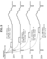
- the frequency folding information is inserted between one vertical synchronous signal and the next subsequent vertical synchronous signal, as shown in 201 through 204 of Figure 3, and more desirably is inserted between any one horizontal synchronous signal and the next subsequent horizontal synchronous signal in an interval between one vertical synchronous signal and the next vertical synchronous signal.
- the position setter 50 supplies frequency folding information DF generated from the frequency folding information generator 40 to the second input terminal of the adder 60.
- the frequency folding information DF supplied to the second input terminal of the adder 60 may be, as shown in 201 through 204 of Figure 3, a pulse in which the inserting position of the pulse may be slightly altered for each field.
- the pulse may be any pulse having a form such as an impulse or a rectangular wave pulse.
- the frequency folding information DF may be a code word with the inserting position fixed.
- the adder 60 adds the frequency folding information DF input from the above position setter 50 to the folded luminance signal FL input from the input terminal 5 and supplies the result to the luminance recorder 70.
- the luminance recorder 70 modulates the frequency of the folded luminance signal including frequency folding information and supplies the result to the magnetic recording head 80.
- the magnetic head 80 records the output of the luminance recorder 70 on magnetic tape.
- a magnetic reproducing head 100 is connected to an input terminal of a luminance reproducer 110.
- An output terminal of the luminance reproducer 110 is connected to a first output terminal 105, an input terminal of a position detector 120, and a first input terminal of a frequency folding information separator 130.
- An output terminal of the position detector 120 is connected to a second input terminal of the frequency folding information separator 130.
- An output terminal of the frequency folding information separator 130 is connected to a second output terminal 115.
- the second output terminal 115 is connected to a control terminal of a frequency unfolding circuit (not shown).
- the first output terminal 105 is connected to an input terminal of an A-D converter (not shown).
- the magnetic head 100 reads out the information recorded on magnetic tape and supplies the result to the luminance reproducer 110.
- the luminance reproducer 110 carries out frequency demodulation of the information read out by the magnetic head 100 and generates a luminance signal.
- the demodulated luminance signal is a signal in which high frequency luminance signal components are folded into low frequency luminance signal components, and also includes frequency folding information.
- the position detector 120 separates vertical and horizontal synchronous signals from the luminance signals FL+DF reproduced from the luminance reproducer 110, detects the number of the above separated horizontal synchronous signals during the scanning of the above separated vertical synchronous signal, and generates a position detection signal of a pulse form with a specific logic state for a predetermined time to reach the horizontal scanning line in which the frequency information is inserted.
- the frequency folding information separator 130 samples the frequency folding information DF included in the luminance signal FL+DF according to the position detection signal of a pulse with a specific logic state, and after decoding, supplies the result to the output terminal 115.
- the frequency folding information inserting circuit 340 is connected between a D-A converter 311 and a luminance signal recorder 350.
- the frequency folding information inserting circuit 340 may alternatively be installed between a frequency folder 330 and the D-A converter 311, without changing the effect of the circuit 340.
- A-D converter 310 samples a composite video signal according to a sampling clock of about 10MHz and encodes the sampled signal to generate a digital composite video signal.
- a motion signal separator 322 separates the motion signal representing the amount of movement of pixels on the screen from the digital composite video signal.
- a luminance signal separator 320 separates the spatially derived luminance signal and the temporally derived luminance signal from the digital composite video signal, suitably mixes the two separated luminance signals stated above according to the motion signal, and then supplies the mixed luminance signal to the frequency folder 330.
- a chrominance signal separator 321 separates the chrominance signal from the digital composite video signal.
- the frequency folder 330 attenuates high frequency components of luminance signals (luminance signals above 2.5 MHz) input from the luminance signal separator 320, and performs sub-Nyquist sampling of the attenuated high frequency components by means of the folding carrier wave.
- the frequency folder 330 also mixes the sampled high frequency luminance signals with low frequency luminance signals, generates a folded luminance signal, performs a low pass filtering of the folded luminance signal so as to provide a high frequency cut-off characteristic of 2.5 MHz thereto, and thus generates a desired folded luminance signal.
- the D-A converter 311 converts the digital folded luminance signal input from the frequency folder 330 into an analog form.
- the frequency folding information inserting circuit 340 inserts frequency folding information according to fields during the nth horizontal scanning period of the analog folded luminance signal input from the D-A converter 311.
- a luminance signal recorder 350 frequency-modulates the analog folded luminance signal input from the frequency folding information inserting circuit 340 to enable recording on a recording medium.
- a chrominance/motion signal mixer 360 mixes the motion signal and the chrominance signal and supplies the result to a D-A converter 312.
- the D-A converter 312 converts the chrominance signal mixed with the motion signal in digital form input from the chrominance/motion signal mixer 360 into analog form.
- a chrominance signal recorder 370 amplitude-modulates the chrominance signal input from the D-A converter 312 according to a carrier wave of approximate 629 MHz.
- a chrominance/luminance signal mixer 380 mixes the frequency-modulated luminance signal and the amplitude-modulated chrominance signal and supplies the result to the magnetic recording head 390.
- the magnetic recording head 390 records the output of the chrominance/luminance signal mixer 380 on a magnetic tape.
- an embodiment of a frequency folding information separating circuit 490 is connected between an output terminal of a luminance signal reproducer 420 and a control terminal of a frequency unfolder 450.
- the frequency folding information separating circuit 490 may alternatively be installed between an A-D converter 430 and a low pass filter 440, without changing the effect of the circuit 490.
- the magnetic reproducing head 400 reads out the information recorded on a video tape and supplies the result to a chrominance/luminance signal separator 410.
- the chrominance/luminance signal separator 410 separates the frequency-modulated luminance signal and the amplitude-modulated chrominance signal from the information supplied from the magnetic reproducing head 400.
- the luminance signal reproducer 420 frequency-demodulates the frequency-modulated luminance signal separated from the chrominance/luminance signal separator 410 and generates a luminance signal.
- A-D converter 430 converts the demodulated luminance signal into a multiple-bit digital video signal.
- the low pass filter 440 filters the digital luminance signal and detects luminance signals distributed within the limited bandwidth (within 2.5 MHz).
- the frequency folding information separating circuit 490 separates frequency folding information from the luminance signal input from the luminance signal reproducer 420 and supplies the result to the frequency unfolder 450.
- the frequency unfolder 450 unfolds the high frequency luminance component folded in the filtered luminance signal having a limited bandwidth supplied from the low pass filter 440 into the original frequency band according to the frequency folding information supplied from the above frequency folding information separating circuit 490, suitably mixes the low frequency luminance signal and the high frequency luminance signal according to the magnitude of the motion signal applied from a chrominance/motion signal separator 411, and generates a luminance signal having a full bandwidth.
- a D-A converter 460 converts the unfolded digital luminance signal supplied from the frequency unfolder 450 into an analog form.
- the chrominance signal reproducer 470 amplitude-demodulates the amplitude-modulated chrominance signal and generates a chrominance signal.
- the chrominance signal includes motion signals when reproducing a video tape on which video signals are recorded by a video cassette recorder to which the circuits embodying this invention are applied.
- A-D converter 431 converts the demodulated chrominance signal into a digital chrominance signal.
- the chrominance/motion signal separator 411 separates the digital chrominance signal into the motion signal and the chrominance signal, and supplies the motion signal to frequency unfolder 450, and supplies the chrominance signal to D-A converter 461.
- D-A converter 461 converts the digital chrominance signal input from the chrominance/motion signal separator 411 into an analog form.
- a composite video signal generator 480 mixes the luminance signal output from the D-A converter 460 and the chrominance signal output from the other D-A converter 461 to form a standard composite video signal.
- the composite video signal generator 480 supplies the standard composite video signal to display apparatus.
- the above-described embodiments of the invention enable recording of information on the frequency of the folding carrier wave which changes according to fields by inserting the information in the luminance signal, separating of frequency folding information inserted in the luminance signal, and accurately unfolding the high frequency luminance signal components included in low frequency luminance signal components into the original band during reproduction by recording frequency folding information with the luminance signal.
Abstract
Description
- This invention relates to the inserting and separating of frequency folding information in and from a video signal.
- Generally, a video recording/reproducing apparatus records or reproduces video signals on or from a recording medium. However, the video signal recorded or reproduced on or from a video recording/reproducing apparatus has a bandwidth limited according to the quality of the recording medium.
- A video recording/reproducing apparatus should bring about inclusion of a large amount of information in a limited bandwidth in order to improve horizontal resolution. A technique for improving horizontal resolution by including a large amount of information in a limited bandwidth is described in our co-pending European Patent Application EP 91 307 342.5 filed 09 August 1991, and claiming priority from U. S. Patent Application No. 07/569,029 on the invention titled "Video Signal Recording System" and filed on August 17, 1990.
- According to the above European Patent Application EP 91 307 342.5, after video signal components distributed in the frequency band higher than the frequency band limited by the recording medium (hereinafter referred to as a base band) in video signals are detected and attenuated, the attenuated high frequency video signal component is mixed with a folding carrier wave for placement in the base band, and the above mixed high frequency video signal component is mixed for inclusion in the video signal component within the base band. Here, the frequency of the folding carrier wave is chosen so as to maximize the distances between the luminance signal in the base band and the folding carrier wave in the time, vertical and horizontal directions. The folding carrier wave thus selected is suitably placed at half the maximum vertical frequency, half the maximum time frequency (i.e. Fukinuki hole) in the time and vertical dimensions, and at approximately 5 MHz in the horizontal direction.
- As a result, the frequency of the following carrier wave is established differently by a specific amount between fields. Therefore, information on the frequency of the folding carrier wave according to separate fields must be recorded with the video signals so that, during reproduction, the high frequency video signal component folded into the low frequency video signal component in the base band can be unfolded and reproduced into the original frequency band.
- Preferred embodiments of the present invention aim to provide a frequency folding information inserting circuit for inserting information on the frequency of the folding carrier wave into video signals in a video recording apparatus for recording video information of the frequency band higher than the base band on a recording medium by folding the video information of the frequency band higher than the base band into the video signal component of the base band so as to improve horizontal resolution.
- Another aim is to provide a frequency folding information separating circuit which, in a video reproducing apparatus, is able to separate information on the frequency of the folding carrier wave from the read out video signals so as to read out and reproduce, from a recording medium, video signals which have video signal components of high frequencies higher than the base band and are folded into video signal components of the base band. It is a further aim to provide a frequency folding information generating method which generates frequency folding information to represent a frequency folding state of the folded video signal in a video recording apparatus for folding a high frequency video signal into a low frequency video signal and recording the folded video signal so as to store a video signal having a full bandwidth on a recording medium having a limited bandwidth.
- According to a first aspect of the present invention, there is provided a frequency folding information inserting circuit in a video recording apparatus for folding a high frequency video signal into a low frequency video signal and recording the folded video signal having a full bandwidth on a recording medium having a limited bandwidth, said circuit comprising:
an even/odd number field detector for detecting whether said folded video signal is of an even number field or an odd number field, and generating an even/odd number field detector signal of different logic states according to the detected result;
a frequency folding information generator for responding to said even/odd number field detector signal to generate frequency folding information representing the frequency folding state of said folded video signal;
an adder for adding the folded video signal to said frequency folding information; and
a position setter connected between said frequency folding information generator and said adder, and for supplying said frequency folding information to said adder when reaching a position where the frequency folding information is to be inserted into the folded video signal. - Preferably, said position of insertion of said frequency folding information is set between one vertical synchronous signal and the next subsequent vertical synchronous signal.
- Preferably, said position of insertion of said frequency folding information is set between an arbitrary horizontal synchronous signal and the next subsequent horizontal synchronous signal in an interval between one vertical synchronous signal and the next subsequent vertical synchronous signal.
- Preferably, said frequency folding information is positioned during any arbitrary horizontal scanning period.
- According to another aspect of the present invention, there is provided a frequency folding information separating circuit in a video reproducing apparatus including a luminance reproducer for reproducing a folded luminance signal from a video signal recorded by folding a high frequency video signal into a low frequency video signal so as to record the folded video signal of a full bandwidth on a recording medium of a limited bandwidth, and a frequency unfolder for generating a luminance signal of a full bandwidth by unfolding the folded high frequency luminance signal into the original frequency band, said circuit comprising:
a position detector for detecting an insertion position of frequency folding information from synchronous signals included in said reproduced luminance signal; and
a frequency folding information separator for separating the frequency folding information inserted in said reproduced luminance signal by responding to the detected result of said position detector and supplying the separated frequency folding information to said frequency unfolder. - Preferably, said position detector comprises a synchronous signal separator for separating the synchronous signals from the reproduced luminance signal.
- According to a further aspect of the present invention, there is provided a frequency folding information generating method for representing a frequency folding state of a folded video signal in a video recording apparatus for folding a high frequency video signal into a low frequency video signal and for recording the folded video signal of a full bandwidth on a recording medium of a limited bandwidth, said method comprising the steps of:
separating a horizontal synchronous signal and a vertical synchronous signal from the folded video signal including synchronous signals;
generating a standard clock pulse train having a frequency which is a predetermined number of times higher than that of the horizontal synchronous signal;
counting up a scanning period of the horizontal synchronous signal according to said standard clock pulse train;
comparing the counted value with a value corresponding to a half-period of the horizontal synchronous signal when a blanking duration of the vertical synchronous signal starts during said counting-up step;
generating an even/odd number field detection signal of a predetermined logic state according to the compared result at said comparing step;
generating frequency folding information according to the logic state of said generated even/odd number field detection signal; and
setting a position of a scanning line for inserting said frequency folding information. - Preferably, a value of said frequency folding information is increased by one for every inversion of the logic state of the even/odd number field detection signal in said generating step of said frequency folding information.
- Preferably, said frequency folding information takes a value of "0" after reaching a specified value in said generating step of said frequency folding information.
- Said frequency folding information may take a value of "0" after reaching a value of "3".
- Said frequency folding information may be a pulse in which an inserting position of the pulse is slightly altered for each field.
- Said frequency folding information may be an impulse in which an inserting position of the impulse is slightly altered for each field.
- Said frequency folding information may be a code word with a fixed inserting position.
- Said frequency folding information may be generated to be inserted in only any one field of four fields of the video signal in said generating step of the frequency folding information.
- Said frequency folding information may be generated to be inserted in only any two fields of four fields of the video signal.
- Said frequency folding information may be generated to be inserted in only any three fields of four fields of the video signal.
- In another aspect of the invention, a frequency folding information inserting circuit comprises:
an even/odd number field detector for detecting whether a video signal on an input terminal is of an odd number field or an even number field;
a frequency folding information generator for generating frequency folding information representing a frequency folding state according to the detected result of the even/odd number field detector;
an adder for inserting the frequency folding information into the video signal supplied at the input terminal; and
a position setter connected between the adder and the frequency folding information generator for supplying the generated frequency folding information to the adder at an arbitrary point of time. - In a further aspect of the invention, a frequency folding information separating circuit comprises:
- a position detector for detecting the position where frequency folding information has been inserted within a reproduced video signal; and
- a frequency folding information separator for separating the frequency folding information included in the reproduced video signal according to the detected result of the position detector.
- For a better understanding of the invention, and to show how the same may be carried into effect, reference will now be made, by way of example, to the accompanying diagrammatic drawings, in which:
- Figure 1 is a block diagram of one example of an embodiment of a frequency folding information inserting circuit according to the invention;
- Figure 2 is a block diagram of one example of an embodiment of a frequency folding information separating circuit according to the invention;
- Figure 3 illustrates video signal waveforms including frequency folding information;
- Figure 4 is a block diagram of an example of a video recording system to which a frequency folding information inserting circuit embodying the invention is applied; and
- Figure 5 is a block diagram of an example of a video reproducing system to which a frequency folding information separating circuit embodying the invention is applied.
- In the circuit for inserting frequency folding information, as shown in Figure 1,
input terminal 5 is connected to a frequency folder (not shown) to receive folded luminance signals including synchronous signals. Also,input terminal 5 is connected to a first input terminal of anadder 60 and an input terminal of asynchronous signal separator 10. An output terminal of astandard clock generator 20 is connected to a third input terminal of an even/odd number field detector 30 (hereinafter, referred to as E/O field detector) and a third input terminal of aposition setter 50. First and second output terminals of thesynchronous signal separator 10 are connected to first and second input terminals of the E/O field detector 30 and first and second input terminals of theposition setter 50. An output terminal of the E/O field detector 30 is connected to an input terminal of a frequency folding information generator 40. An output terminal of the frequency folding information generator 40 is connected to a fourth input terminal of theposition setter 50. An output terminal of theposition setter 50 is connected to a second input terminal of theadder 60. An output terminal of theadder 60 is connected to an input terminal of aluminance recorder 70. An output terminal of theluminance recorder 70 is connected to amagnetic recording head 80. - In operation of the circuit, the
synchronous signal separator 10 separates the horizontal and vertical synchronous signals HS and VS from the folded luminance signal FL including the synchronous signals and supplies the separated synchronous signals to the E/O field detector 30 and theposition setter 50. - The
standard clock generator 20 generates a standard clock pulse train RC with a frequency much higher than that of the horizontal synchronous signals HS. For example, the frequency of the standard clock pulse train takes a value of 320fH or 640fH. Here, fH is the frequency of the horizontal synchronous signal. - E/
O field detector 30 performs a count up of the scanning period of the horizontal synchronous signals HS by the standard clock pulse train RS, and when the blanking period of the vertical synchronous signal VS starts during the count, detects whether the counted value is larger than the value corresponding to the half-period of the horizontal synchronous signal HS. The E/O field detector 30 generates an E/O field detector signal FCS of a predetermined logic state, representing that the folded luminance signal input to theinput terminal 5 is an even number field if the counted value is greater than the half-period value of the horizontal synchronous signal HS, and conversely, generates an E/O field detector signal FCS of a logic state opposite to that in the case of an even number field, representing that the folded luminance signal input to theinput terminal 5 is an odd number field if the counted value is less than the half-period value of the horizontal synchronous signal HS. - The frequency folding information generator 40 generates frequency folding information DF increasing by one for every inversion of the logic state of the E/O field detector signal FCS. The above frequency folding information takes a value of "0" after reaching a specified value (actually "3").
- That is, the frequency folding information generator 40 applied to the frequency folding information inserting circuit of the illustrated embodiment of the invention generates frequency folding information DF increasing by one for every field of the video signals as described above. Accordingly, frequency folding information DF which are repeated by a period of four fields may be inserted into predetermined scanning lines of the video signals. However, in another embodiment of the present invention, the frequency folding information generator 40 may be constructed to generate the frequency folding information DF only for any one field among the four fields of the video signals. On the other hand, in a still further embodiment, the frequency folding information generator 40 may be constructed to generate the frequency folding information DF only for any two fields or three fields among the four fields of the video signals.
- The
position setter 50 counts the number of horizontal synchronous signals HS to select the position of the scanning line for inserting the frequency folding information from the vertical synchronous signal VS, and upon reaching the desired scanning line, counts the standard clock pulse train to set the position for inserting frequency folding information. The frequency folding information is inserted between one vertical synchronous signal and the next subsequent vertical synchronous signal, as shown in 201 through 204 of Figure 3, and more desirably is inserted between any one horizontal synchronous signal and the next subsequent horizontal synchronous signal in an interval between one vertical synchronous signal and the next vertical synchronous signal. Whenever a position is set, theposition setter 50 supplies frequency folding information DF generated from the frequency folding information generator 40 to the second input terminal of theadder 60. Here, the frequency folding information DF supplied to the second input terminal of theadder 60 may be, as shown in 201 through 204 of Figure 3, a pulse in which the inserting position of the pulse may be slightly altered for each field. Here, the pulse may be any pulse having a form such as an impulse or a rectangular wave pulse. Otherwise, the frequency folding information DF may be a code word with the inserting position fixed. - The
adder 60 adds the frequency folding information DF input from theabove position setter 50 to the folded luminance signal FL input from theinput terminal 5 and supplies the result to theluminance recorder 70. - The
luminance recorder 70 modulates the frequency of the folded luminance signal including frequency folding information and supplies the result to themagnetic recording head 80. - The
magnetic head 80 records the output of theluminance recorder 70 on magnetic tape. - In the circuit for separating frequency folding information, as shown in Figure 2, a magnetic reproducing
head 100 is connected to an input terminal of aluminance reproducer 110. An output terminal of theluminance reproducer 110 is connected to afirst output terminal 105, an input terminal of aposition detector 120, and a first input terminal of a frequencyfolding information separator 130. An output terminal of theposition detector 120 is connected to a second input terminal of the frequency foldinginformation separator 130. An output terminal of the frequency foldinginformation separator 130 is connected to asecond output terminal 115. Thesecond output terminal 115 is connected to a control terminal of a frequency unfolding circuit (not shown). Thefirst output terminal 105 is connected to an input terminal of an A-D converter (not shown). - In operation of the circuit of Figure 2, the
magnetic head 100 reads out the information recorded on magnetic tape and supplies the result to theluminance reproducer 110. - The
luminance reproducer 110 carries out frequency demodulation of the information read out by themagnetic head 100 and generates a luminance signal. Here, the demodulated luminance signal is a signal in which high frequency luminance signal components are folded into low frequency luminance signal components, and also includes frequency folding information. - The
position detector 120 separates vertical and horizontal synchronous signals from the luminance signals FL+DF reproduced from theluminance reproducer 110, detects the number of the above separated horizontal synchronous signals during the scanning of the above separated vertical synchronous signal, and generates a position detection signal of a pulse form with a specific logic state for a predetermined time to reach the horizontal scanning line in which the frequency information is inserted. - The frequency
folding information separator 130 samples the frequency folding information DF included in the luminance signal FL+DF according to the position detection signal of a pulse with a specific logic state, and after decoding, supplies the result to theoutput terminal 115. - In the video recording system of Figure 4, an embodiment of a frequency folding information inserting circuit according to this invention is applied. Referring to Figure 4, the frequency folding
information inserting circuit 340 is connected between aD-A converter 311 and aluminance signal recorder 350. - However, the frequency folding
information inserting circuit 340 may alternatively be installed between afrequency folder 330 and theD-A converter 311, without changing the effect of thecircuit 340. - An example of the operation of the video recording system shown in Figure 4 is described as follows.
-
A-D converter 310 samples a composite video signal according to a sampling clock of about 10MHz and encodes the sampled signal to generate a digital composite video signal. Amotion signal separator 322 separates the motion signal representing the amount of movement of pixels on the screen from the digital composite video signal. - A
luminance signal separator 320 separates the spatially derived luminance signal and the temporally derived luminance signal from the digital composite video signal, suitably mixes the two separated luminance signals stated above according to the motion signal, and then supplies the mixed luminance signal to thefrequency folder 330. - A
chrominance signal separator 321 separates the chrominance signal from the digital composite video signal. - The
frequency folder 330 attenuates high frequency components of luminance signals (luminance signals above 2.5 MHz) input from theluminance signal separator 320, and performs sub-Nyquist sampling of the attenuated high frequency components by means of the folding carrier wave. Thefrequency folder 330 also mixes the sampled high frequency luminance signals with low frequency luminance signals, generates a folded luminance signal, performs a low pass filtering of the folded luminance signal so as to provide a high frequency cut-off characteristic of 2.5 MHz thereto, and thus generates a desired folded luminance signal. - The
D-A converter 311 converts the digital folded luminance signal input from thefrequency folder 330 into an analog form. - The frequency folding
information inserting circuit 340 inserts frequency folding information according to fields during the nth horizontal scanning period of the analog folded luminance signal input from theD-A converter 311. - A
luminance signal recorder 350 frequency-modulates the analog folded luminance signal input from the frequency foldinginformation inserting circuit 340 to enable recording on a recording medium. - A chrominance/
motion signal mixer 360 mixes the motion signal and the chrominance signal and supplies the result to aD-A converter 312. - The
D-A converter 312 converts the chrominance signal mixed with the motion signal in digital form input from the chrominance/motion signal mixer 360 into analog form. - A
chrominance signal recorder 370 amplitude-modulates the chrominance signal input from theD-A converter 312 according to a carrier wave of approximate 629 MHz. - A chrominance/
luminance signal mixer 380 mixes the frequency-modulated luminance signal and the amplitude-modulated chrominance signal and supplies the result to themagnetic recording head 390. Themagnetic recording head 390 records the output of the chrominance/luminance signal mixer 380 on a magnetic tape. - In the video reproducing system of Figure 5, an embodiment of a frequency folding
information separating circuit 490 is connected between an output terminal of aluminance signal reproducer 420 and a control terminal of afrequency unfolder 450. - However, the frequency folding
information separating circuit 490 may alternatively be installed between anA-D converter 430 and alow pass filter 440, without changing the effect of thecircuit 490. - An example of the operation of the video reproducing system shown in Figure 5 is described as follows.
- The magnetic reproducing
head 400 reads out the information recorded on a video tape and supplies the result to a chrominance/luminance signal separator 410. - The chrominance/
luminance signal separator 410 separates the frequency-modulated luminance signal and the amplitude-modulated chrominance signal from the information supplied from the magnetic reproducinghead 400. - The
luminance signal reproducer 420 frequency-demodulates the frequency-modulated luminance signal separated from the chrominance/luminance signal separator 410 and generates a luminance signal. -
A-D converter 430 converts the demodulated luminance signal into a multiple-bit digital video signal. - The
low pass filter 440 filters the digital luminance signal and detects luminance signals distributed within the limited bandwidth (within 2.5 MHz). The frequency foldinginformation separating circuit 490 separates frequency folding information from the luminance signal input from theluminance signal reproducer 420 and supplies the result to thefrequency unfolder 450. - The
frequency unfolder 450 unfolds the high frequency luminance component folded in the filtered luminance signal having a limited bandwidth supplied from thelow pass filter 440 into the original frequency band according to the frequency folding information supplied from the above frequency foldinginformation separating circuit 490, suitably mixes the low frequency luminance signal and the high frequency luminance signal according to the magnitude of the motion signal applied from a chrominance/motion signal separator 411, and generates a luminance signal having a full bandwidth. AD-A converter 460 converts the unfolded digital luminance signal supplied from thefrequency unfolder 450 into an analog form. - The
chrominance signal reproducer 470 amplitude-demodulates the amplitude-modulated chrominance signal and generates a chrominance signal. The chrominance signal includes motion signals when reproducing a video tape on which video signals are recorded by a video cassette recorder to which the circuits embodying this invention are applied. -
A-D converter 431 converts the demodulated chrominance signal into a digital chrominance signal. - The chrominance/
motion signal separator 411 separates the digital chrominance signal into the motion signal and the chrominance signal, and supplies the motion signal tofrequency unfolder 450, and supplies the chrominance signal toD-A converter 461. -
D-A converter 461 converts the digital chrominance signal input from the chrominance/motion signal separator 411 into an analog form. - A composite
video signal generator 480 mixes the luminance signal output from theD-A converter 460 and the chrominance signal output from the otherD-A converter 461 to form a standard composite video signal. The compositevideo signal generator 480 supplies the standard composite video signal to display apparatus. - The above-described embodiments of the invention enable recording of information on the frequency of the folding carrier wave which changes according to fields by inserting the information in the luminance signal, separating of frequency folding information inserted in the luminance signal, and accurately unfolding the high frequency luminance signal components included in low frequency luminance signal components into the original band during reproduction by recording frequency folding information with the luminance signal.
- The reader's attention is directed to all papers and documents which are filed concurrently with or previous to this specification in connection with this application and which are open to public inspection with this specification, and the contents of all such papers and documents are incorporated herein by reference.
- All of the features disclosed in this specification (including any accompanying claims, abstract and drawings), and/or all of the steps of any method or process so disclosed, may be combined in any combination, except combinations where at least some of such features and/or steps are mutually exclusive
- Each feature disclosed in this specification (including any accompanying claims, abstract and drawings), may be replaced by alternative features serving the same, equivalent or similar purpose, unless expressly stated otherwise. Thus, unless expressly stated otherwise, each feature disclosed is one example only of a generic series of equivalent or similar features.
- The invention is not restricted to the details of the foregoing embodiment(s). The invention extends to any novel one, or any novel combination, of the features disclosed in this specification (including any accompanying claims, abstract and drawings), or to any novel one, or any novel combination, of the steps of any method or process so disclosed.
Claims (16)
- A frequency folding information inserting circuit (340) in a video recording apparatus for folding a high frequency video signal into a low frequency video signal and recording the folded video signal (FL) having a full bandwidth on a recording medium having a limited bandwidth, said circuit (340) comprising:
an even/odd number field detector (30) for detecting whether said folded video signal (FL) is of an even number field or an odd number field, and generating an even/odd number field detector signal (FCS) of different logic states according to the detected result;
a frequency folding information generator (40) for responding to said even/odd number field detector signal (FCS) to generate frequency folding information (DF) representing the frequency folding state of said folded video signal (FL);
an adder (60) for adding the folded video signal (FL) to said frequency folding information (DF); and
a position setter (50) connected between said frequency folding information generator (40) and said adder (60), and for supplying said frequency folding information (DF) to said adder (60) when reaching a position where the frequency folding information (DF) is to be inserted into the folded video signal (FL). - A frequency folding information inserting circuit as claimed in claim 1, wherein said position of insertion of said frequency folding information (DF) is set between one vertical synchronous signal (VS) and the next subsequent vertical synchronous signal (VS).
- A frequency folding information inserting circuit as claimed in claim 2, wherein said position of insertion of said frequency folding information (DF) is set between an arbitrary horizontal synchronous signal (HS) and the next subsequent horizontal synchronous signal (HS) in an interval between one vertical synchronous signal (VS) and the next subsequent vertical synchronous signal (VS).
- A frequency folding information inserting circuit as claimed in claim 3, wherein said frequency folding information (DF) is positioned during any arbitrary horizontal scanning period (HS).
- A frequency folding information separating circuit (490) in a video reproducing apparatus including a luminance reproducer (420) for reproducing a folded luminance signal from a video signal recorded by folding a high frequency video signal into a low frequency video signal so as to record the folded video signal of a full bandwidth on a recording medium of a limited bandwidth, and a frequency unfolder (450) for generating a luminance signal of a full bandwidth by unfolding the folded high frequency luminance signal into the original frequency band, said circuit (490) comprising:
a position detector (120) for detecting an insertion position of frequency folding information from synchronous signals included in said reproduced luminance signal; and
a frequency folding information separator (130) for separating the frequency folding information inserted in said reproduced luminance signal by responding to the detected result of said position detector (120) and supplying the separated frequency folding information to said frequency unfolder (450). - A frequency folding information separating circuit as claimed in claim 5, wherein said position detector (120) comprises a synchronous signal separator for separating the synchronous signals from the reproduced luminance signal.
- A frequency folding information generating method for representing a frequency folding state of a folded video signal in a video recording apparatus for folding a high frequency video signal into a low frequency video signal and for recording the folded video signal of a full bandwidth on a recording medium of a limited bandwidth, said method comprising the steps of:
separating a horizontal synchronous signal and a vertical synchronous signal from the folded video signal including synchronous signals;
generating a standard clock pulse train having a frequency which is a predetermined number of times higher than that of the horizontal synchronous signal;
counting up a scanning period of the horizontal synchronous signal according to said standard clock pulse train;
comparing the counted value with a value corresponding to a half-period of the horizontal synchronous signal when a blanking duration of the vertical synchronous signal starts during said counting-up step;
generating an even/odd number field detection signal of a predetermined logic state according to the compared result at said comparing step;
generating frequency folding information according to the logic state of said generated even/odd number field detection signal; and
setting a position of a scanning line for inserting said frequency folding information. - A frequency folding information generating method as claimed in claim 7, wherein a value of said frequency folding information is increased by one for every inversion of the logic state of the even/odd number field detection signal in said generating step of said frequency folding information.
- A frequency folding information generating method as claimed in claim 8, wherein said frequency folding information takes a value of "0" after reaching a specified value in said generating step of said frequency folding information.
- A frequency folding information generating method as claimed in claim 9, wherein said frequency folding information takes a value of "0" after reaching a value of "3".
- A frequency folding information generating method as claimed in claim 7, wherein said frequency folding information is a pulse in which an inserting position of the pulse is slightly altered for each field.
- A frequency folding information generating method as claimed in claim 7, wherein said frequency folding information is an impulse in which an inserting position of the impulse is slightly altered for each field.
- A frequency folding information generating method as claimed in claim 7, wherein said frequency folding information is a code word with a fixed inserting position.
- A frequency folding information generating method as claimed in claim 7, wherein said frequency folding information is generated to be inserted in only any one field of four fields of the video signal in said generating step of the frequency folding information.
- A frequency folding information generating method as claimed in claim 7, wherein said frequency folding information is generated to be inserted in only any two fields of four fields of the video signal.
- A frequency folding information generating method as claimed in claim 7, wherein said frequency folding information is generated to be inserted in only any three fields of four fields of the video signal.
Priority Applications (1)
| Application Number | Priority Date | Filing Date | Title |
|---|---|---|---|
| EP96102840A EP0719056B1 (en) | 1990-10-31 | 1991-10-31 | Frequency folding information inserting circuit |
Applications Claiming Priority (2)
| Application Number | Priority Date | Filing Date | Title |
|---|---|---|---|
| KR9017587 | 1990-10-31 | ||
| KR1019900017587A KR930002795B1 (en) | 1990-10-31 | 1990-10-31 | Frequency filing-up data inserting and seperating circuit |
Related Child Applications (2)
| Application Number | Title | Priority Date | Filing Date |
|---|---|---|---|
| EP96102840.4 Division-Into | 1991-10-31 | ||
| EP96102840A Division EP0719056B1 (en) | 1990-10-31 | 1991-10-31 | Frequency folding information inserting circuit |
Publications (3)
| Publication Number | Publication Date |
|---|---|
| EP0484154A2 true EP0484154A2 (en) | 1992-05-06 |
| EP0484154A3 EP0484154A3 (en) | 1993-05-05 |
| EP0484154B1 EP0484154B1 (en) | 1996-12-18 |
Family
ID=19305474
Family Applications (2)
| Application Number | Title | Priority Date | Filing Date |
|---|---|---|---|
| EP91310061A Expired - Lifetime EP0484154B1 (en) | 1990-10-31 | 1991-10-31 | Inserting and separating frequency folding information |
| EP96102840A Expired - Lifetime EP0719056B1 (en) | 1990-10-31 | 1991-10-31 | Frequency folding information inserting circuit |
Family Applications After (1)
| Application Number | Title | Priority Date | Filing Date |
|---|---|---|---|
| EP96102840A Expired - Lifetime EP0719056B1 (en) | 1990-10-31 | 1991-10-31 | Frequency folding information inserting circuit |
Country Status (9)
| Country | Link |
|---|---|
| US (1) | US5740302A (en) |
| EP (2) | EP0484154B1 (en) |
| JP (1) | JP3110107B2 (en) |
| KR (1) | KR930002795B1 (en) |
| CN (1) | CN1029184C (en) |
| CA (1) | CA2052225C (en) |
| DE (2) | DE69123706T2 (en) |
| ES (2) | ES2182923T3 (en) |
| RU (1) | RU2087080C1 (en) |
Cited By (8)
| Publication number | Priority date | Publication date | Assignee | Title |
|---|---|---|---|---|
| EP0471517A2 (en) * | 1990-08-17 | 1992-02-19 | Samsung Electronics Co., Ltd. | Video signal recording and/or reproducing systems |
| US5500739A (en) * | 1990-05-31 | 1996-03-19 | Samsung Electronics Co., Ltd. | Frequency-multiplexing FM luma signal with color and 2nd under signals having overlapping frequency spectra |
| US5596418A (en) * | 1990-08-17 | 1997-01-21 | Samsung Electronics Co., Ltd. | Deemphasis and subsequent reemphasis of high-energy reversed-spectrum components of a folded video signal |
| US5673355A (en) * | 1990-08-17 | 1997-09-30 | Samsung Electronics Co., Ltd. | Deemphasis & Subsequent reemphasis of high-energy reversed-spectrum components of a folded video signal |
| US5822490A (en) * | 1990-05-31 | 1998-10-13 | Samsung Electronics Co., Ltd. | Apparatus and method for color-under chroma channel encoded with a high frequency luminance signal |
| US6134373A (en) * | 1990-08-17 | 2000-10-17 | Samsung Electronics Co., Ltd. | System for recording and reproducing a wide bandwidth video signal via a narrow bandwidth medium |
| US6246827B1 (en) | 1990-08-17 | 2001-06-12 | Samsung Electronics Co., Ltd. | Deemphasis and subsequent reemphasis of high-energy reversed-spectrum components of a folded video signal |
| US6253022B1 (en) | 1990-08-17 | 2001-06-26 | Samsung Electronics Co., Ltd. | Video signal encoded with additional detail information |
Families Citing this family (3)
| Publication number | Priority date | Publication date | Assignee | Title |
|---|---|---|---|---|
| CN1158865C (en) * | 1994-09-26 | 2004-07-21 | 三菱电机株式会社 | Digital video signal record and playback device and method for recording and playing back the same |
| GB9421206D0 (en) * | 1994-10-20 | 1994-12-07 | Thomson Consumer Electronics | Digital VCR MPEG- trick play processing |
| US7953293B2 (en) * | 2006-05-02 | 2011-05-31 | Ati Technologies Ulc | Field sequence detector, method and video device |
Citations (2)
| Publication number | Priority date | Publication date | Assignee | Title |
|---|---|---|---|---|
| US3947870A (en) * | 1973-07-24 | 1976-03-30 | Hitachi, Ltd. | Receiving system for auxiliary information signal transmitted during the vertical blanking period of a television signal |
| US4745460A (en) * | 1983-03-18 | 1988-05-17 | Hitachi, Ltd. | Method for transmitting a television signal by field to field processing |
Family Cites Families (14)
| Publication number | Priority date | Publication date | Assignee | Title |
|---|---|---|---|---|
| US5063457A (en) * | 1986-11-19 | 1991-11-05 | Canon Kabushiki Kaisha | Wide-band video signal recording apparatus by using frequency interleave |
| US4831463A (en) * | 1987-01-30 | 1989-05-16 | Faroudja Y C | Video processing in which high frequency luminance components are folded into a mid-band spectrum |
| US4819059A (en) * | 1987-11-13 | 1989-04-04 | Polaroid Corporation | System and method for formatting a composite still and moving image defining electronic information signal |
| JPH01221070A (en) * | 1988-02-29 | 1989-09-04 | Casio Comput Co Ltd | Image information processor |
| US4912549A (en) * | 1988-09-07 | 1990-03-27 | Rca Licensing Corporation | Video signal synchronization system as for an extended definition widescreen television signal processing system |
| US5012239A (en) * | 1989-08-21 | 1991-04-30 | Visa-Trak Corporation | High resolution position sensor circuit |
| US5023727A (en) * | 1989-10-12 | 1991-06-11 | Ian A. R. Boyd | Method and device for producing a substantially continuous composite video signal |
| JPH03132183A (en) * | 1989-10-18 | 1991-06-05 | Hitachi Ltd | Digital image reproducing system |
| US5025496A (en) * | 1990-05-07 | 1991-06-18 | Rca Licensing Corporation | Odd/even field detector for video signals |
| US5113262A (en) * | 1990-08-17 | 1992-05-12 | Samsung Electronics Co., Ltd. | Video signal recording system enabling limited bandwidth recording and playback |
| KR930012145B1 (en) * | 1990-10-31 | 1993-12-24 | 삼성전자 주식회사 | Brightness signal reproducing circuit and method of different system |
| US5208707A (en) * | 1990-10-31 | 1993-05-04 | Samsung Electronics Co., Ltd. | Circuit for maintaining compatibility between different image systems during reproduction having an adaptive de-emphasis unit |
| KR930008182B1 (en) * | 1990-11-27 | 1993-08-26 | 삼성전자 주식회사 | Motion signal detecting circuit |
| KR940007160B1 (en) * | 1991-06-27 | 1994-08-06 | 삼성전자 주식회사 | Method and device for folding dynamic applied frequency |
-
1990
- 1990-10-31 KR KR1019900017587A patent/KR930002795B1/en not_active IP Right Cessation
-
1991
- 1991-09-20 US US07/763,291 patent/US5740302A/en not_active Expired - Fee Related
- 1991-09-25 CA CA002052225A patent/CA2052225C/en not_active Expired - Fee Related
- 1991-10-22 JP JP03274192A patent/JP3110107B2/en not_active Expired - Fee Related
- 1991-10-30 RU SU915010108A patent/RU2087080C1/en not_active IP Right Cessation
- 1991-10-31 ES ES96102840T patent/ES2182923T3/en not_active Expired - Lifetime
- 1991-10-31 ES ES91310061T patent/ES2098332T3/en not_active Expired - Lifetime
- 1991-10-31 DE DE69123706T patent/DE69123706T2/en not_active Expired - Fee Related
- 1991-10-31 CN CN91110547A patent/CN1029184C/en not_active Expired - Fee Related
- 1991-10-31 EP EP91310061A patent/EP0484154B1/en not_active Expired - Lifetime
- 1991-10-31 EP EP96102840A patent/EP0719056B1/en not_active Expired - Lifetime
- 1991-10-31 DE DE69133117T patent/DE69133117T2/en not_active Expired - Fee Related
Patent Citations (2)
| Publication number | Priority date | Publication date | Assignee | Title |
|---|---|---|---|---|
| US3947870A (en) * | 1973-07-24 | 1976-03-30 | Hitachi, Ltd. | Receiving system for auxiliary information signal transmitted during the vertical blanking period of a television signal |
| US4745460A (en) * | 1983-03-18 | 1988-05-17 | Hitachi, Ltd. | Method for transmitting a television signal by field to field processing |
Non-Patent Citations (3)
| Title |
|---|
| ELECTRONICS 6 February 1967, pages 101 - 103 'Pulses on a television signal control stations in network' * |
| NTZ NACHRICHTENTECHNISCHE ZEITSCHRIFT vol. 29, no. 3, 1976, BERLIN DE pages 240 - 248 NUMAGUCHI 'Wie man stillstehende Bilder überträgt' * |
| SMPTE JOURNAL August 1985, pages 814 - 820 HAYES 'Vertical-Interval Encoding for the Recordable Laser Videodisc' * |
Cited By (9)
| Publication number | Priority date | Publication date | Assignee | Title |
|---|---|---|---|---|
| US5500739A (en) * | 1990-05-31 | 1996-03-19 | Samsung Electronics Co., Ltd. | Frequency-multiplexing FM luma signal with color and 2nd under signals having overlapping frequency spectra |
| US5822490A (en) * | 1990-05-31 | 1998-10-13 | Samsung Electronics Co., Ltd. | Apparatus and method for color-under chroma channel encoded with a high frequency luminance signal |
| EP0471517A2 (en) * | 1990-08-17 | 1992-02-19 | Samsung Electronics Co., Ltd. | Video signal recording and/or reproducing systems |
| EP0471517A3 (en) * | 1990-08-17 | 1993-03-17 | Samsung Electronics Co., Ltd. | Video signal recording and/or reproducing systems |
| US5596418A (en) * | 1990-08-17 | 1997-01-21 | Samsung Electronics Co., Ltd. | Deemphasis and subsequent reemphasis of high-energy reversed-spectrum components of a folded video signal |
| US5673355A (en) * | 1990-08-17 | 1997-09-30 | Samsung Electronics Co., Ltd. | Deemphasis & Subsequent reemphasis of high-energy reversed-spectrum components of a folded video signal |
| US6134373A (en) * | 1990-08-17 | 2000-10-17 | Samsung Electronics Co., Ltd. | System for recording and reproducing a wide bandwidth video signal via a narrow bandwidth medium |
| US6246827B1 (en) | 1990-08-17 | 2001-06-12 | Samsung Electronics Co., Ltd. | Deemphasis and subsequent reemphasis of high-energy reversed-spectrum components of a folded video signal |
| US6253022B1 (en) | 1990-08-17 | 2001-06-26 | Samsung Electronics Co., Ltd. | Video signal encoded with additional detail information |
Also Published As
| Publication number | Publication date |
|---|---|
| CN1029184C (en) | 1995-06-28 |
| EP0484154B1 (en) | 1996-12-18 |
| EP0719056A3 (en) | 1996-09-04 |
| DE69133117D1 (en) | 2002-10-24 |
| EP0484154A3 (en) | 1993-05-05 |
| CA2052225A1 (en) | 1992-05-01 |
| CA2052225C (en) | 1996-05-21 |
| RU2087080C1 (en) | 1997-08-10 |
| ES2098332T3 (en) | 1997-05-01 |
| JP3110107B2 (en) | 2000-11-20 |
| ES2182923T3 (en) | 2003-03-16 |
| DE69123706D1 (en) | 1997-01-30 |
| US5740302A (en) | 1998-04-14 |
| KR930002795B1 (en) | 1993-04-10 |
| EP0719056B1 (en) | 2002-09-18 |
| DE69133117T2 (en) | 2003-01-16 |
| EP0719056A2 (en) | 1996-06-26 |
| JPH04332282A (en) | 1992-11-19 |
| CN1062067A (en) | 1992-06-17 |
| DE69123706T2 (en) | 1997-06-19 |
| KR920008719A (en) | 1992-05-28 |
Similar Documents
| Publication | Publication Date | Title |
|---|---|---|
| US4597019A (en) | Clock pulse generating circuit in a color video signal reproducing apparatus | |
| JP2667900B2 (en) | Recording and playback device | |
| EP0719056B1 (en) | Frequency folding information inserting circuit | |
| US4626929A (en) | Color video signal recording and reproducing apparatus | |
| KR930010360B1 (en) | Restoring circuit for corresponding signal | |
| US4628369A (en) | Video signal dropout compensation circuit | |
| GB2249451A (en) | A circuit for folding the high frequency component of a luminance signal | |
| EP0138573A1 (en) | Multiplexed color video signal recording and reproducing apparatus | |
| JPH0685587B2 (en) | Playback device | |
| EP0169013B1 (en) | Video signal recording and reproducing apparatus | |
| CA1249365A (en) | Process for recording and playback of tv-signals in analog form | |
| EP0140706B1 (en) | Jitter-immune time expansion for time-compressed line-sequential video signals | |
| US4692814A (en) | Jitter-immune time expansion for time-compressed line-sequential video signals | |
| JP2982271B2 (en) | Image playback device | |
| KR0155693B1 (en) | Caption information recording reproducing apparatus and its method | |
| JP3180586B2 (en) | Video signal processing device | |
| JPH0134512B2 (en) | ||
| JPH0832065B2 (en) | Video signal recording method | |
| JPH0325759A (en) | Recording system discriminating method in reproducing device | |
| CN1061690A (en) | The recording/reproducing circuit of time base error correction reference signal | |
| JPS6370690A (en) | Picture recording and reproducing device | |
| JPH09182110A (en) | Method and device for generating decoding clock for digital data element | |
| JPS61258590A (en) | Picture recording and reproducing device | |
| JPH01192061A (en) | Video floppy reproducing device | |
| JPH0678333A (en) | Video signal recording and reproducing device |
Legal Events
| Date | Code | Title | Description |
|---|---|---|---|
| PUAI | Public reference made under article 153(3) epc to a published international application that has entered the european phase |
Free format text: ORIGINAL CODE: 0009012 |
|
| AK | Designated contracting states |
Kind code of ref document: A2 Designated state(s): DE ES GB NL |
|
| PUAL | Search report despatched |
Free format text: ORIGINAL CODE: 0009013 |
|
| AK | Designated contracting states |
Kind code of ref document: A3 Designated state(s): DE ES GB NL |
|
| 17P | Request for examination filed |
Effective date: 19931012 |
|
| 17Q | First examination report despatched |
Effective date: 19950127 |
|
| GRAG | Despatch of communication of intention to grant |
Free format text: ORIGINAL CODE: EPIDOS AGRA |
|
| GRAH | Despatch of communication of intention to grant a patent |
Free format text: ORIGINAL CODE: EPIDOS IGRA |
|
| GRAH | Despatch of communication of intention to grant a patent |
Free format text: ORIGINAL CODE: EPIDOS IGRA |
|
| GRAA | (expected) grant |
Free format text: ORIGINAL CODE: 0009210 |
|
| AK | Designated contracting states |
Kind code of ref document: B1 Designated state(s): DE ES GB NL |
|
| DX | Miscellaneous (deleted) | ||
| REF | Corresponds to: |
Ref document number: 69123706 Country of ref document: DE Date of ref document: 19970130 |
|
| REG | Reference to a national code |
Ref country code: ES Ref legal event code: FG2A Ref document number: 2098332 Country of ref document: ES Kind code of ref document: T3 |
|
| PLBE | No opposition filed within time limit |
Free format text: ORIGINAL CODE: 0009261 |
|
| STAA | Information on the status of an ep patent application or granted ep patent |
Free format text: STATUS: NO OPPOSITION FILED WITHIN TIME LIMIT |
|
| 26N | No opposition filed | ||
| REG | Reference to a national code |
Ref country code: GB Ref legal event code: IF02 |
|
| PGFP | Annual fee paid to national office [announced via postgrant information from national office to epo] |
Ref country code: NL Payment date: 20081005 Year of fee payment: 18 |
|
| PGFP | Annual fee paid to national office [announced via postgrant information from national office to epo] |
Ref country code: DE Payment date: 20081027 Year of fee payment: 18 |
|
| PGFP | Annual fee paid to national office [announced via postgrant information from national office to epo] |
Ref country code: ES Payment date: 20081121 Year of fee payment: 18 |
|
| PGFP | Annual fee paid to national office [announced via postgrant information from national office to epo] |
Ref country code: GB Payment date: 20081029 Year of fee payment: 18 |
|
| REG | Reference to a national code |
Ref country code: NL Ref legal event code: V1 Effective date: 20100501 |
|
| PG25 | Lapsed in a contracting state [announced via postgrant information from national office to epo] |
Ref country code: NL Free format text: LAPSE BECAUSE OF NON-PAYMENT OF DUE FEES Effective date: 20100501 Ref country code: DE Free format text: LAPSE BECAUSE OF NON-PAYMENT OF DUE FEES Effective date: 20100501 |
|
| PG25 | Lapsed in a contracting state [announced via postgrant information from national office to epo] |
Ref country code: GB Free format text: LAPSE BECAUSE OF NON-PAYMENT OF DUE FEES Effective date: 20091031 |
|
| REG | Reference to a national code |
Ref country code: ES Ref legal event code: FD2A Effective date: 20110309 |
|
| PG25 | Lapsed in a contracting state [announced via postgrant information from national office to epo] |
Ref country code: ES Free format text: LAPSE BECAUSE OF NON-PAYMENT OF DUE FEES Effective date: 20110308 |
|
| PG25 | Lapsed in a contracting state [announced via postgrant information from national office to epo] |
Ref country code: ES Free format text: LAPSE BECAUSE OF NON-PAYMENT OF DUE FEES Effective date: 20091101 |