EP0484918A2 - Improved cellular telephone service using spread spectrum transmission - Google Patents
Improved cellular telephone service using spread spectrum transmission Download PDFInfo
- Publication number
- EP0484918A2 EP0484918A2 EP91118930A EP91118930A EP0484918A2 EP 0484918 A2 EP0484918 A2 EP 0484918A2 EP 91118930 A EP91118930 A EP 91118930A EP 91118930 A EP91118930 A EP 91118930A EP 0484918 A2 EP0484918 A2 EP 0484918A2
- Authority
- EP
- European Patent Office
- Prior art keywords
- spread spectrum
- vehicle location
- voice
- digital
- signals
- Prior art date
- Legal status (The legal status is an assumption and is not a legal conclusion. Google has not performed a legal analysis and makes no representation as to the accuracy of the status listed.)
- Granted
Links
Images


Classifications
-
- H—ELECTRICITY
- H04—ELECTRIC COMMUNICATION TECHNIQUE
- H04W—WIRELESS COMMUNICATION NETWORKS
- H04W88/00—Devices specially adapted for wireless communication networks, e.g. terminals, base stations or access point devices
- H04W88/08—Access point devices
-
- H—ELECTRICITY
- H04—ELECTRIC COMMUNICATION TECHNIQUE
- H04W—WIRELESS COMMUNICATION NETWORKS
- H04W64/00—Locating users or terminals or network equipment for network management purposes, e.g. mobility management
Definitions
- the present invention relates generally to cellular telephone systems, and more particularly,to a cellular telephone system that employs spread spectrum transmission to provide additional services without degrading the existing voice communications service, while utilizing much of the present cellular telephone infrastructure.
- the cellular telephone band was designed to carry a large number of two-way voice conversations to mobile users.
- vehicle location and messaging services In addition to two way voice communication, there is interest in using the cellular telephone band to provide vehicle location and messaging services, emergency SOS information, and vehicle anti-theft protection services, for example.
- current systems that are confined to narrow band voice channels of the cellular band produce location accuracies that are about two orders of magnitude lower than are required to provide these services, and these are generally not useful for most applications.
- the present invention enables the incorporation of messaging and vehicle location capabilities into existing cellular services without causing objectionable interference to users of the cellular voice channels.
- a spread spectrum processor that utilizes a unique signal architecture/waveform design is the key to this capability.
- the system of the present invention is designed to share the existing cellular frequencies, cell site real estate, cell site antenna towers and antennas, and low noise amplifiers used in the cell site radio frequency receiver chain.
- the only additional cell site equipment is a unique spread spectrum signal processor.
- New mobile telephone equipment for deployment in vehicles would include a spread spectrum transmitter in accordance with the present invention.
- this system has the economic viability for both regional and nationwide deployment.
- the vehicular electronics package requires a much lower power transmitter because the transmission distances are of the order of 20 miles, instead of 20,000 miles for systems that use satellites. Vehicle transmitter power may be reduced from hundreds of watts to less than one watt with a consequent downward revision in cost per unit.
- the present invention permits dual usage of the frequency spectrum assigned for cellular telephone service.
- voice conversations are supported by dividing the spectral space into individual 30 KHz channels.
- Cellular service suppliers are assigned blocks of channels in contiguous fashion covering bandwidths in excess of 10 MHz.
- digital signalling is supported in the same spectral space and in the presence of the existing voice traffic.
- no objectionable interference is generated to affect the existing traffic since the spread spectrum transmissions are either below the normal noise levels for digital messaging, or of such short duration that they are imperceptible in the normal burst noise background for position location applications.
- Class I is a digital messaging service that permits the simultaneous transmission from nominally 100 vehicles each sending data messages at the rate of 300 bits per second to access the normal telephone network.
- Class II provides for the accurate location of vehicles, with accuracies on the order of 100 feet.
- the applications of this technology are numerous. For instance, if a motion sensor coupled to the system identifies that a vehicle theft is in progress,thus energizing the vehicular transmitter, the system permits location tracking of the vehicle for law enforcement officers. Police, ambulance and/or tow truck service may be directed to an exact location. Customized yellow pages directory service which depends on knowledge of vehicle location may also be facilitated.
- a burst spread waveform pattern having a burst duration on the order of 10 milliseconds or less is employed to maximize location accuracy and to minimize interference which is naturally suppressed by the clipping action of the existing narrowband cellular FM receivers.
- the spread spectrum system employes rapid synchronization techniques and uses a single code for access to the system by the transmitting vehicle.
- a waveform variant may be used.
- the entire band of cellular frequencies could be divided into n (say 10) narrower spread spectrum channels with center frequencies at f1 through f n .
- each burst transmission (the pulse amplitude and duration remain unchanged) would be sent at a new center frequency.
- the reduced bandwidth transmissions sacrifices some location accuracy, but distributes the imperceptible voice channel blockage to a new set of voice users with each transmission. Thus, the non-objectionable interference characteristic is preserved.
- CW continuous wave
- the service request and power control architecture is employed to minimize interference and maximize message capacity.
- the system could use a number of separate spread spectrum codes to facilitate load distribution within a cell site and between cell sites.
- the code reuse concept is analogous to the frequency reuse technique currently in use in the existing cellular system.
- the present invention provides for the following. First, it provides a means of radiating from a vehicle a signal in the transmit band of the national cellular telephone system without causing objectionable interference to the voice telephone users of that band. Second, it provides a means for achieving vehicle location accuracies that are improved by greater than two orders of magnitude over that which is possible by the current transmissions in that band. Third, it incorporates a means of achieving transmit power control of the vehicle transmitter to combat the extremely large variation (dynamic range) of radio signal path loss to the receiving sites. The main variables are distance and the multipath caused by intervening obstructions to the line of site due to buildings, terrain features and other vehicles. Fourth, it incorporates a means of excising at the receiver the excessively strong conventional voice cellular signals that are not under power control which ordinarily might interfere with the successful reception of the new broadband signals.
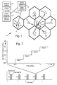
- Fig. 1 illustrates a cellular system 10 implemented using the principles of the present invention, and also illustrates the operation of the two main services provided by the present invention, namely, vehicle location and messaging services. More specifically, the cellular system 10 includes a plurality of cell sites 13, 20-26. A first vehicle having a first vehicle transmitter 11 is located within a central cell site 20 while a second vehicle is located within a local cell site 13. The first transmitter 11 is shown transmitting a vehicle location signal 29 to each of the local cell sites 20-26 adjacent thereto. The second transmitter 12 is shown transmitting a digital message 18 or second spread spectrum signal 18 to the local cell site 13, while the local cell site 13 is shown transmitting a probe signal 29, which signals will be described in more detail below.
- the local cell site 13 and cell sites 20-26 are coupled to a mobile telephone switching office (MTSO) 14 by way of a microwave communications link 17 which in turn is coupled through a public switched telephone network 15 by way of the microwave communications link 17 to a regional location processing center 16 using a wired connection path 30.
- MTSO mobile telephone switching office
- the conventional aspects of the cellular system 10 are well known to those in the cellular communications art and the conventional aspects of its design and operation will not be described in detail herein.
- Fig. 2 shows the details of a typical cell site 21, but also includes a spread spectrum processor 40 in accordance with the principles of the present invention.
- the typical cell site 21 comprises an antenna 31 that is coupled to a low noise amplifier 32.
- the low noise amplifier 32 is coupled by way of a 48:1 power splitter 33 to a plurality of receivers 34, typically a subset of the 333 possible receive channels assigned to a single service provider and then to a land based telephone system.
- the output of the receivers 34 are voice signals that are coupled to the public switched telephone network 15.
- the spread spectrum processor 40 in accordance with the principles of the present invention is coupled to one output of the 48:1 power splitter 33 and is in turn coupled to the mobile telephone switching office (MTSO) 14, the public switched telephone network 15, and the regional location processing center 16, as described above.
- MTSO mobile telephone switching office
- the spread spectrum processor 40 of the present invention is designed to share the existing cellular frequencies, cell site real estate, cell site antenna towers and antennas, and cell site low noise amplifiers and cell site power splitters.
- the incorporation of the processor 40 into the cellular system has the economic viability for both regional and nationwide deployment.
- the vehicular electronics package for use with the present invention (described with reference to Figs. 4 and 5 below) requires a much lower power transmitter because of the transmission distances are of the order of 20 miles, instead of 20,000 miles for systems that use satellites.
- Vehicular transmitter powers may be reduced from hundreds of watts to less than one watt with a consequent downward revision in cost per transmitter 11.
- the present invention permits dual usage of the frequency spectrum assigned for cellular telephone service.
- voice conversations are supported by dividing the spectral space into individual 30 KHz channels.
- Cellular service suppliers are assigned blocks of channels in contiguous fashion covering bandwidths in excess of 10 MHz.
- digital signalling is supported in the same spectral space and in the presence of the existing voice traffic.
- no objectionable interference is generated to affect the existing traffic since the spread spectrum transmissions are either below the normal noise levels for digital messaging, or of such short duration that they are imperceptible in the normal burst noise background for position location applications.
- Spread spectrum processors such as the spread spectrum processor 40 are generally well known in the art, and reference is made to U.S. Patent No. 4,740,792, the contents of which is incorporated herein by reference.
- the spread spectrum processor described therein may be readily adapted for use in the present invention. Modifications to the 4,740,792 processor and the characteristics of the present invention are described hereinbelow.
- the present invention may employ a modified Position Location and Reporting System (PLRS) spread spectrum processor, which is manufactured by Hughes Aircraft Company, the assignee of the present invention, for the U.S. Army.
- PLRS Position Location and Reporting System
- Fig. 3 illustrates the details of the spread spectrum processor 40 of Fig. 2.
- the spread spectrum processor 40 comprises a low noise amplifier 41 that is coupled to a hybrid coupler 42.
- One output of the hybrid coupler 42 is coupled to one or more time of arrival correlators 43 that are adapted to respond to a Class I message (Code "A"), and transfer output signals therefrom through a data buffer 44 to the regional location processing center 16 by way of conventional telephone lines.
- the correlator 43 is adapted to sort out signals that may overlap one another due to near-simultaneous, random transmission from different transmitters 11 so that corresponding time differences of arrival of signals received at different cell sites 20-26 transmitted by a particular transmitter 11 may be determined later at the regional location processing center 16 where the individual transmitter locations may be determined.
- the other output of the hybrid coupler 42 is coupled to a message preamble correlator 45 comprising a bank of "P" correlators adapted to respond to a Class II message (Code "B"), and transfer output signals therefrom through a message correlator 46, comprising a bank of "M” correlators and a corresponding plurality of message buffers, to the public switched telephone network 15 through the mobile switching office 14.
- a message preamble correlator 45 comprising a bank of "P” correlators adapted to respond to a Class II message (Code "B")
- message correlator 46 comprising a bank of "M” correlators and a corresponding plurality of message buffers
- Fig. 4 illustrates a typical vehicle transmitter 11 incorporating the principles of the present invention that may be employed for the purposes of transmitting emergency information, and the like.
- the transmitter 11 incorporates a reference oscillator or clock 51, a sequencer or operation timer 52, a memory 53 comprising a PROM 54 and a buffer 55, a logic controller 56, a low pass filter 57 an exciter 58, a power amplifier 59, a pulse forming network 61, and an antenna 60.
- the exciter 58 comprises an UHF oscillator 63, a phase lock loop 64, and a summer 65.
- optional devices including a motion sensor 66, a crash sensor 67, a vehicle anti-theft system 68 and a manual message selector 69.
- the motion sensor 66 and crash sensor 67 preferably comprise conventional accelerometers which may be set or selected for different levels of acceleration.
- the anti-theft system 68 is any commercially available anti-theft apparatus that provides an electric signal in response to vehicle intrusion, tampering or unauthorized movement.
- the message selector 69 may comprise a conventional keyboard or switch (not shown) by means of which several prestored message codes may be selected for encoding in the transmission the of the transmitter 11.
- the sequencer 52 controls RF signal repetition rate and formatting of a transmitted RF signal.
- the memory 53 which may comprise the PROM 54, and the data buffer 55, for example, contain signal formatting information, including a transmitter identification code and specific message codes. Codes for a predetermined number of messages, and "accident" or “need assistance” codes may be stored in the PROM 54 and automatically selected by signals from the crash sensor 67 or anti-theft system 68, or manually selected by the manual message selector 69, and which are transmitted under control of the logic controller 56.
- a burst spread waveform pattern having a burst duration on the order of 10 milliseconds or less is employed to maximize location accuracy and to minimize interference which is naturally suppressed by the clipping action of the existing narrowband cellular FM receivers.
- the spread spectrum system employes rapid synchronization techniques and uses a single code for access to the system by the transmitting vehicle.
- a waveform variant may be used.
- the entire band of cellular frequencies may be divided into n (say 10) narrower spread spectrum channels with center frequencies at f1 through f n .
- each burst transmission (the pulse amplitude and duration remain unchanged) is sent at a new center frequency.
- the reduced bandwidth transmissions sacrifices some location accuracy, but distributes the imperceptible voice channel blockage to a new set of voice users with each transmission. Thus, the non-objectionable interference characteristic is preserved.
- Fig. 5 illustrates a typical vehicle transmitter 12 incorporating the principles of the present invention that may be employed for the purposes of transmitting messages. It is to be understood that the transmitters 11, 12 shown in Figs. 4 and 5 may be integrated into one single transmitter, and are not limited to use as stand alone units.
- the transmitter 12 incorporates many of the components described with reference to Fig. 4, including the reference oscillator 51, the memory 53, the logic controller 56, the low pass filter 57, the exciter 58, the power amplifier 59, and the antenna 60. Replacing the remainder of the components is a keyboard 66 that is coupled through a data buffer 67 to the logic controller 56. In operation, the logic controller 56 selects respective inputs from either the keyboard 66 or the memory 53 for transmission from the transmitter 12 in a conventional manner.
- a below the noise continuous wave (CW) spread spectrum waveform is employed which is naturally suppressed by the FM limiters in the existing narrowband cellular receivers 34 (Fig. 2).
- a service request and power control architecture is employed to minimize interference and maximize message capacity.
- the system may employ a number of separate spread spectrum codes to facilitate load distribution within a cell site and between cell sites.
- the code reuse concept is substantially analogous to the frequency reuse technique currently in use in the existing cellular system.
- Fig. 6 illustrates a data processor 75 located in the regional location processing center 15 that processes vehicle location signals 29 produced in accordance with the principles of the present invention and transmitted from the cell sites 20-26 to the regional location processing center 16.
- the data processor 75 comprises a time of arrival (TOA) accumulator 77, a time difference of arrival (TDOA) processor 78, a data processor 79, an operator display and controller 80 and a subscriber interface 81.
- the subscriber interface 81 comprises a plurality of modems 82 that are adapted to transmit computed location information to subscribers over conventional phone lines.
- Time of arrival measurements made at the cell sites 20-26 are fed to the accumulator 77 where they are sorted by ID.
- the individual transmitter locations may be determined in a manner described in U.S. Patent No. 4,740,792. More detailed information regarding the design and operation of the transmitter 11 and data processing station may be had from a reading of U.S. Patent No. 4,740,792.
- the technique for establishing power level control over the vehicle transmitters 11, 12 is as follows.
- One standard administrative cellular telephone channel (30 KHz wide) is set aside to communicate from cell sites 13, 20-26 to vehicles using the probe signal 29. Because of the greater transmit power available at cell sites, a high rate transmission, TDMA (time division multiple access) digital communications signal is employed.
- the probe signal 29 is transmitted from cell sites 13, 20-26 to achieve an initial power level setting on the transmitters 11, 12 in vehicles that wish to communicate. On the assumption that most radio frequency transmission paths are bilateral, the probe signal 29 having the form shown in Fig. 7 is employed.
- the probe signal 29 comprising a short duration pulse (approximately 8 msec) is transmitted every second from each cell site 13, 20-26 with a staircase power level that changes in intensity by 15 dB per step, for example. If the step #1 signal is too weak to be heard by a particular vehicle transmitter 11, 12, the vehicle transmitter 11, 12 waits until reception is possible at one of the higher power levels.
- the transmission at each level contains information bits defining the transmitted power levels, the cell site identification number, and the noise levels of signals at that cell site receiver. In this manner, the vehicle transmitter 11, 12 derives information enabling it to set its own power level for successful reception at that site 13, 20-26.
- the signals transmitted from other cell sites 13, 20-26 are synchronized in time to assure that they do not overlap at a vehicle transmitter 11, 12. In this manner the optimum cell site receiver is selected. This minimizes the transmit power thus maximizing the overall system capacity.
- the first vehicle transmitter 11 radiates a short (approximately 1 millisecond) burst of spread spectrum coded location signal 28 utilizing a 5 megachip per second (for example) code rate.
- the short burst duration does not cause objectionable interference even at full power.
- Full power is used to help ensure reception at the more distant cell cites 21-26.
- the signal power is spread over a wide bandwidth (100 times the normal voice transmission bandwidth) and therefore its energy density is in the noise of the standard voice signal.
- the location signal 28 is received at cell sites 20-26, for example. For proper location the location signal 28 need only be heard at three of the seven adjacent sites 20-26.
- the spread spectrum signal processor 40 at each cell site 20-26 decodes the signal to determine the exact time of arrival of the signal, an identification number of the vehicle transmitting the signal, and unique data bits that identify the class of service requested.
- This decoded data is "packetized" and sent to the regional location processing center 16.
- the function of the regional location processing center 16 is to collect and sort all of the information packets concerning a single vehicle transmitter 11 and calculate the difference in the time of arrival of a single transmission burst at respective pairs of cell sites 20-26 that heard the signal 28. Each such pair creates a hyperbolic line of position. At the intersection of at least two of these lines of position, a vehicle location is declared in two dimensional space.
- a transmitted message signal comprising the digital message 18 (second spread spectrum signal 18), need only be heard at a single cell site 15. Therefore the signal transmit level of the digital message 18 may be reduced in amplitude from that of the vehicle location signal 28 when messages at 300 bits per second are sent, for example.
- the messages are typical data messages that are handled in the same manner as voice messages, except that the digital messages are encoded by spread spectrum techniques.
- the digital message 18 is transmitted to the cell site 13 where its class is decoded. It is then transferred to the public switched telephone network 15 for transmission to the destination contained in the digital message 18.
- Class I is digital messaging service that permits simultaneous transmission from nominally 100 vehicles each sending data messages at the rate of 300 bits per second to access the public switched telephone network 15.
- Class II provides for the accurate location of vehicles, with accuracies on the order of 100 feet.
- the applications of this technology are numerous. For instance, if the motion sensor 66 or anti-theft system 69 (Fig. 4) identifies that a vehicle theft is in progress, the system permits location tracking of the vehicle which is reported to law enforcement officers in real time. Police, ambulance and/or tow truck service may be directed to an exact location determined by the present system. Customized yellow pages directory service which depends on knowledge of vehicle location may also be provided.
- the present invention achieves for the following. It provides for additional communication capability using the national cellular telephone system without causing objectionable interference to the voice telephone users. It provides a means for determining vehicle location accuracies that are improved by greater than two orders of magnitude over that which is possible by the current transmissions in the cellular band. It provides for transmit power control of a vehicle transmitter 12 to combat the extremely large variation (dynamic range) of radio signal path loss to the cell sites 20-26. It employs an excisor which removes excessively strong conventional voice cellular signals that are not under power control which ordinarily might interfere with the successful reception of the broadband spread spectrum signals 18, 28.
- the effect of the spread spectrum signals on a narrow band cellular channel is as follows. Given a 3 KHz voice information rate require a a 3 watt power level, a 300 Hz data information rate requires a a 0.3 watt power level. Therefore, a +10 dB advantage exists for the voice signal. Given a 30 kHz voice transmission bandwidth, and a 24 MHz data transmission bandwidth, a +29 dB spreading factor exists. Therefore, a +39 dB voice signal advantage per spread spectrum signal exists. Given a -20 dB loss for 100 simultaneous spread spectrum signals, the signal to noise ratio for the narrow band voice signal is +19 dB for 100 simultaneous spread spectrum channels, which is accepted as good quality by the cellular industry.
- the effect of all the voice channel transmissions and the spread spectrum transmissions on the successful reception of a single object spread spectrum transmission is as follows. Given a 24 MHz data transmission bandwidth and a 300 Hz data information rate, a 49 dB processing gain is achieved. If the cellular voice channels are fully loaded, there are 666 narrow band users using 3 watts of power, and this yields 2000 watts of noise (interference) power. If the spread spectrum channel is fully loaded, there are 100 wide band users using 0.3 watts of power, which yields 30 watts of noise (interference) power. This results in a total noise (interference) power of 2030 watts. One spread spectrum user times 0.3 watts yields a 0.3 watt signal power.
- the input signal to noise ratio for the spread spectrum channel is -38 dB. If the processing gain is 49 dB, the output signal to noise ratio is then +11 dB. If there is a +9 dB threshold for adequate bit error rate performance, a margin of 2 dB is provided. However, a communications network is rarely if ever fully loaded, so that additional margin is indicated.
- the present invention also provides for flexibility in resource allocation that is achievable by the system 10 using spread spectrum modulation techniques.
- the present invention provides for matching the channel resource allocation to functional needs, and permits simultaneous mix of different data rate users. For example, the present system permits 100 users to transmit at a 300 bit per second data rate using a 0.3 watt power level, or 10 users to transmit at a 3000 bit per second data rate using a 3.0 watt power level, or 1 user to transmit at a 30,000 bit per second data rate using a 30.0 watt power level.
Abstract
Description
- The present invention relates generally to cellular telephone systems, and more particularly,to a cellular telephone system that employs spread spectrum transmission to provide additional services without degrading the existing voice communications service, while utilizing much of the present cellular telephone infrastructure.
- The cellular telephone band was designed to carry a large number of two-way voice conversations to mobile users. In addition to two way voice communication, there is interest in using the cellular telephone band to provide vehicle location and messaging services, emergency SOS information, and vehicle anti-theft protection services, for example. However, current systems that are confined to narrow band voice channels of the cellular band produce location accuracies that are about two orders of magnitude lower than are required to provide these services, and these are generally not useful for most applications.
- Previous nationwide vehicle location systems, disclosed in U.S. Patent Nos. 4,359,733 and 4,740,792, for example, have not come to fruition to date because of the relatively high start up capital cost of using satellites. Other nationwide location systems are planned (TELETRAC and GEOSTAR), but they operate in frequency bands other than the cellular band and therefore require a very expensive special purpose infrastructure. The IBM-Motorola mobile data service currently operational in the New York, Chicago and Los Angeles areas also requires a special purpose infrastructure which results in high usage fees.
- The use of spread spectrum communications in conjunction with the cellular voice channel has been investigated in recent years. One implementation proposed by Qualcomm, Inc. of San Diego, California, would partition the cellular band such that a 1 MHz frequency band would be dedicated to each of the transmit and receive bands for spread spectrum voice communication, while the balance of the two bands would continue to provide standard cellular service. As spread spectrum systems increased in usage, the spread spectrum portion of the bands would increase in size to match the need. It is apparent that, since this proposed system requires its own dedicated frequency subbands, that the Qualcomm implementation of spread spectrum communication would interfere with the operation of the standard cellular voice channels.
- Accordingly, it is an objective of the present invention to employ technology that overlays the narrow band cellular telephone voice signals with wide band spread spectrum signals to provide for messaging and vehicle tracking capabilities without adversely affecting the quality or capacity of the voice channels.
- The present invention enables the incorporation of messaging and vehicle location capabilities into existing cellular services without causing objectionable interference to users of the cellular voice channels. A spread spectrum processor that utilizes a unique signal architecture/waveform design is the key to this capability.
- Through the use of wide bandwidth spread spectrum radio transmissions overlaid over the existing cellular voice signals, new services which depend on the ability to accurately locate vehicles are provided. In addition, a second class of spread spectrum radio transmissions supports a large number of users transmitting low rate digital messages. Both areas of functionality (vehicle location and messages) are obtained without sacrificing any of the existing voice channel capacity. By employing the concepts of the present invention, since a large fraction of the cellular telephone infrastructure may be used in common, a large savings in deployment costs results.
- The system of the present invention is designed to share the existing cellular frequencies, cell site real estate, cell site antenna towers and antennas, and low noise amplifiers used in the cell site radio frequency receiver chain. The only additional cell site equipment is a unique spread spectrum signal processor. New mobile telephone equipment for deployment in vehicles would include a spread spectrum transmitter in accordance with the present invention. Thus, this system has the economic viability for both regional and nationwide deployment. When compared to a nationwide system using a satellite infrastructure, the vehicular electronics package requires a much lower power transmitter because the transmission distances are of the order of 20 miles, instead of 20,000 miles for systems that use satellites. Vehicle transmitter power may be reduced from hundreds of watts to less than one watt with a consequent downward revision in cost per unit.
- The present invention permits dual usage of the frequency spectrum assigned for cellular telephone service. Currently voice conversations are supported by dividing the spectral space into individual 30 KHz channels. Cellular service suppliers are assigned blocks of channels in contiguous fashion covering bandwidths in excess of 10 MHz. Through the use of unique spread spectrum waveforms (which spread energy over the full 10 MHz bandwidth), digital signalling is supported in the same spectral space and in the presence of the existing voice traffic. At the same time no objectionable interference is generated to affect the existing traffic since the spread spectrum transmissions are either below the normal noise levels for digital messaging, or of such short duration that they are imperceptible in the normal burst noise background for position location applications.
- Two new classes of functionality are created by the present invention. Class I is a digital messaging service that permits the simultaneous transmission from nominally 100 vehicles each sending data messages at the rate of 300 bits per second to access the normal telephone network. The other class of digital signalling (Class II) provides for the accurate location of vehicles, with accuracies on the order of 100 feet. The applications of this technology are numerous. For instance, if a motion sensor coupled to the system identifies that a vehicle theft is in progress,thus energizing the vehicular transmitter, the system permits location tracking of the vehicle for law enforcement officers. Police, ambulance and/or tow truck service may be directed to an exact location. Customized yellow pages directory service which depends on knowledge of vehicle location may also be facilitated.
- For vehicle location, a burst spread waveform pattern having a burst duration on the order of 10 milliseconds or less is employed to maximize location accuracy and to minimize interference which is naturally suppressed by the clipping action of the existing narrowband cellular FM receivers. For vehicle location, the spread spectrum system employes rapid synchronization techniques and uses a single code for access to the system by the transmitting vehicle.
- In anti-theft applications, when it is necessary to make a number of sequential location measurements in a relatively short period of time, a waveform variant may be used. In this case, the entire band of cellular frequencies could be divided into n (say 10) narrower spread spectrum channels with center frequencies at f₁ through fn. Then each burst transmission (the pulse amplitude and duration remain unchanged) would be sent at a new center frequency. The reduced bandwidth transmissions sacrifices some location accuracy, but distributes the imperceptible voice channel blockage to a new set of voice users with each transmission. Thus, the non-objectionable interference characteristic is preserved.
- For messaging, a below the noise continuous wave (CW) spread spectrum waveform is employed which is naturally suppressed by the FM limiters in the existing narrowband cellular receivers. The service request and power control architecture is employed to minimize interference and maximize message capacity. The system could use a number of separate spread spectrum codes to facilitate load distribution within a cell site and between cell sites. The code reuse concept is analogous to the frequency reuse technique currently in use in the existing cellular system.
- In summary, the present invention provides for the following. First, it provides a means of radiating from a vehicle a signal in the transmit band of the national cellular telephone system without causing objectionable interference to the voice telephone users of that band. Second, it provides a means for achieving vehicle location accuracies that are improved by greater than two orders of magnitude over that which is possible by the current transmissions in that band. Third, it incorporates a means of achieving transmit power control of the vehicle transmitter to combat the extremely large variation (dynamic range) of radio signal path loss to the receiving sites. The main variables are distance and the multipath caused by intervening obstructions to the line of site due to buildings, terrain features and other vehicles. Fourth, it incorporates a means of excising at the receiver the excessively strong conventional voice cellular signals that are not under power control which ordinarily might interfere with the successful reception of the new broadband signals.
- The various features and advantages of the present invention may be more readily understood with reference to the following detailed description taken in conjunction with the accompanying drawings, wherein like reference numerals designate like structural elements, and in which:
- Fig. 1 illustrates a cellular system incorporating spread spectrum signal processors in accordance with the principles of the present invention;
- Fig. 2 shows the details of a typical cell site incorporating the present invention;
- Fig. 3 illustrates the details of the spread spectrum processor of Fig. 2;
- Figs. 4 and 5 illustrate typical vehicle transmitter configurations incorporating the principles of the present invention;
- Fig. 6 illustrates a data processing station located in a regional location processing center that processes data obtained from signals produced in accordance with the principles of the present invention; and
- Fig. 7 is useful in illustrating a technique for establishing power level control that employs a multi-step probe signal.
- With reference to the drawings, Fig. 1 illustrates a
cellular system 10 implemented using the principles of the present invention, and also illustrates the operation of the two main services provided by the present invention, namely, vehicle location and messaging services. More specifically, thecellular system 10 includes a plurality ofcell sites 13, 20-26. A first vehicle having afirst vehicle transmitter 11 is located within acentral cell site 20 while a second vehicle is located within alocal cell site 13. Thefirst transmitter 11 is shown transmitting avehicle location signal 29 to each of the local cell sites 20-26 adjacent thereto. Thesecond transmitter 12 is shown transmitting adigital message 18 or secondspread spectrum signal 18 to thelocal cell site 13, while thelocal cell site 13 is shown transmitting aprobe signal 29, which signals will be described in more detail below. Thelocal cell site 13 and cell sites 20-26 (but not shown for diagram clarity) are coupled to a mobile telephone switching office (MTSO) 14 by way of a microwave communications link 17 which in turn is coupled through a public switchedtelephone network 15 by way of the microwave communications link 17 to a regionallocation processing center 16 using awired connection path 30. The conventional aspects of thecellular system 10 are well known to those in the cellular communications art and the conventional aspects of its design and operation will not be described in detail herein. - Fig. 2 shows the details of a
typical cell site 21, but also includes aspread spectrum processor 40 in accordance with the principles of the present invention. Thetypical cell site 21 comprises anantenna 31 that is coupled to alow noise amplifier 32. Thelow noise amplifier 32 is coupled by way of a 48:1power splitter 33 to a plurality ofreceivers 34, typically a subset of the 333 possible receive channels assigned to a single service provider and then to a land based telephone system. The output of thereceivers 34 are voice signals that are coupled to the public switchedtelephone network 15. Thespread spectrum processor 40 in accordance with the principles of the present invention is coupled to one output of the 48:1power splitter 33 and is in turn coupled to the mobile telephone switching office (MTSO) 14, the public switchedtelephone network 15, and the regionallocation processing center 16, as described above. - The
spread spectrum processor 40 of the present invention is designed to share the existing cellular frequencies, cell site real estate, cell site antenna towers and antennas, and cell site low noise amplifiers and cell site power splitters. Thus, the incorporation of theprocessor 40 into the cellular system has the economic viability for both regional and nationwide deployment. In addition, the vehicular electronics package for use with the present invention (described with reference to Figs. 4 and 5 below) requires a much lower power transmitter because of the transmission distances are of the order of 20 miles, instead of 20,000 miles for systems that use satellites. Vehicular transmitter powers may be reduced from hundreds of watts to less than one watt with a consequent downward revision in cost pertransmitter 11. - The present invention permits dual usage of the frequency spectrum assigned for cellular telephone service. Currently voice conversations are supported by dividing the spectral space into individual 30 KHz channels. Cellular service suppliers are assigned blocks of channels in contiguous fashion covering bandwidths in excess of 10 MHz. Through the use of unique spread spectrum waveforms (which spread energy over the full 10 MHz bandwidth), digital signalling is supported in the same spectral space and in the presence of the existing voice traffic. At the same time no objectionable interference is generated to affect the existing traffic since the spread spectrum transmissions are either below the normal noise levels for digital messaging, or of such short duration that they are imperceptible in the normal burst noise background for position location applications.
- Spread spectrum processors, such as the
spread spectrum processor 40 are generally well known in the art, and reference is made to U.S. Patent No. 4,740,792, the contents of which is incorporated herein by reference. The spread spectrum processor described therein may be readily adapted for use in the present invention. Modifications to the 4,740,792 processor and the characteristics of the present invention are described hereinbelow. In addition, the present invention may employ a modified Position Location and Reporting System (PLRS) spread spectrum processor, which is manufactured by Hughes Aircraft Company, the assignee of the present invention, for the U.S. Army. - Fig. 3 illustrates the details of the
spread spectrum processor 40 of Fig. 2. Thespread spectrum processor 40 comprises alow noise amplifier 41 that is coupled to ahybrid coupler 42. One output of thehybrid coupler 42 is coupled to one or more time ofarrival correlators 43 that are adapted to respond to a Class I message (Code "A"), and transfer output signals therefrom through adata buffer 44 to the regionallocation processing center 16 by way of conventional telephone lines. Thecorrelator 43 is adapted to sort out signals that may overlap one another due to near-simultaneous, random transmission fromdifferent transmitters 11 so that corresponding time differences of arrival of signals received at different cell sites 20-26 transmitted by aparticular transmitter 11 may be determined later at the regionallocation processing center 16 where the individual transmitter locations may be determined. The other output of thehybrid coupler 42 is coupled to amessage preamble correlator 45 comprising a bank of "P" correlators adapted to respond to a Class II message (Code "B"), and transfer output signals therefrom through amessage correlator 46, comprising a bank of "M" correlators and a corresponding plurality of message buffers, to the public switchedtelephone network 15 through themobile switching office 14. The correlators and buffers comprising themessage preamble correlator 45 andmessage correlator 46 are generally well known and will not be described in detail herein. More detail of these types of devices are provided in U.S. Patent No. 4,740,792. - Fig. 4 illustrates a
typical vehicle transmitter 11 incorporating the principles of the present invention that may be employed for the purposes of transmitting emergency information, and the like. Thetransmitter 11 incorporates a reference oscillator orclock 51, a sequencer oroperation timer 52, amemory 53 comprising aPROM 54 and abuffer 55, alogic controller 56, alow pass filter 57 anexciter 58, apower amplifier 59, apulse forming network 61, and anantenna 60. Theexciter 58 comprises anUHF oscillator 63, aphase lock loop 64, and asummer 65. Also included are optional devices, including amotion sensor 66, acrash sensor 67, avehicle anti-theft system 68 and amanual message selector 69. - The
motion sensor 66 andcrash sensor 67 preferably comprise conventional accelerometers which may be set or selected for different levels of acceleration. Theanti-theft system 68 is any commercially available anti-theft apparatus that provides an electric signal in response to vehicle intrusion, tampering or unauthorized movement. In turn, themessage selector 69 may comprise a conventional keyboard or switch (not shown) by means of which several prestored message codes may be selected for encoding in the transmission the of thetransmitter 11. - In operation, the
sequencer 52 controls RF signal repetition rate and formatting of a transmitted RF signal. Thememory 53, which may comprise thePROM 54, and thedata buffer 55, for example, contain signal formatting information, including a transmitter identification code and specific message codes. Codes for a predetermined number of messages, and "accident" or "need assistance" codes may be stored in thePROM 54 and automatically selected by signals from thecrash sensor 67 oranti-theft system 68, or manually selected by themanual message selector 69, and which are transmitted under control of thelogic controller 56. - Regarding the data transmitted by the
transmitter 11, for vehicle location, a burst spread waveform pattern having a burst duration on the order of 10 milliseconds or less is employed to maximize location accuracy and to minimize interference which is naturally suppressed by the clipping action of the existing narrowband cellular FM receivers. For vehicle location, the spread spectrum system employes rapid synchronization techniques and uses a single code for access to the system by the transmitting vehicle. - In anti-theft applications, when it is necessary to make a number of sequential location measurements in a relatively short period of time, a waveform variant may be used. In this case, the entire band of cellular frequencies may be divided into n (say 10) narrower spread spectrum channels with center frequencies at f₁ through fn. Then each burst transmission (the pulse amplitude and duration remain unchanged) is sent at a new center frequency. The reduced bandwidth transmissions sacrifices some location accuracy, but distributes the imperceptible voice channel blockage to a new set of voice users with each transmission. Thus, the non-objectionable interference characteristic is preserved.
- Fig. 5 illustrates a
typical vehicle transmitter 12 incorporating the principles of the present invention that may be employed for the purposes of transmitting messages. It is to be understood that thetransmitters transmitter 12 incorporates many of the components described with reference to Fig. 4, including thereference oscillator 51, thememory 53, thelogic controller 56, thelow pass filter 57, theexciter 58, thepower amplifier 59, and theantenna 60. Replacing the remainder of the components is akeyboard 66 that is coupled through adata buffer 67 to thelogic controller 56. In operation, thelogic controller 56 selects respective inputs from either thekeyboard 66 or thememory 53 for transmission from thetransmitter 12 in a conventional manner. - Regarding the data transmitted by the
transmitter 12, for messaging, a below the noise continuous wave (CW) spread spectrum waveform is employed which is naturally suppressed by the FM limiters in the existing narrowband cellular receivers 34 (Fig. 2). A service request and power control architecture is employed to minimize interference and maximize message capacity. For example, the system may employ a number of separate spread spectrum codes to facilitate load distribution within a cell site and between cell sites. The code reuse concept is substantially analogous to the frequency reuse technique currently in use in the existing cellular system. - Fig. 6 illustrates a
data processor 75 located in the regionallocation processing center 15 that processes vehicle location signals 29 produced in accordance with the principles of the present invention and transmitted from the cell sites 20-26 to the regionallocation processing center 16. Thedata processor 75 comprises a time of arrival (TOA)accumulator 77, a time difference of arrival (TDOA)processor 78, adata processor 79, an operator display andcontroller 80 and asubscriber interface 81. Thesubscriber interface 81 comprises a plurality ofmodems 82 that are adapted to transmit computed location information to subscribers over conventional phone lines. - Time of arrival measurements made at the cell sites 20-26 are fed to the
accumulator 77 where they are sorted by ID. The individual transmitter locations may be determined in a manner described in U.S. Patent No. 4,740,792. More detailed information regarding the design and operation of thetransmitter 11 and data processing station may be had from a reading of U.S. Patent No. 4,740,792. - With reference to Fig. 7, the technique for establishing power level control over the
vehicle transmitters cell sites 13, 20-26 to vehicles using theprobe signal 29. Because of the greater transmit power available at cell sites, a high rate transmission, TDMA (time division multiple access) digital communications signal is employed. Theprobe signal 29 is transmitted fromcell sites 13, 20-26 to achieve an initial power level setting on thetransmitters probe signal 29 having the form shown in Fig. 7 is employed. Theprobe signal 29 comprising a short duration pulse (approximately 8 msec) is transmitted every second from eachcell site 13, 20-26 with a staircase power level that changes in intensity by 15 dB per step, for example. If thestep # 1 signal is too weak to be heard by aparticular vehicle transmitter vehicle transmitter vehicle transmitter site 13, 20-26. The signals transmitted fromother cell sites 13, 20-26 are synchronized in time to assure that they do not overlap at avehicle transmitter - Referring again to Fig. 1, the overall operation of the system of the present invention will now be described. For vehicle location, the
first vehicle transmitter 11 radiates a short (approximately 1 millisecond) burst of spread spectrumcoded location signal 28 utilizing a 5 megachip per second (for example) code rate. The short burst duration does not cause objectionable interference even at full power. Full power is used to help ensure reception at the more distant cell cites 21-26. In this case the signal power is spread over a wide bandwidth (100 times the normal voice transmission bandwidth) and therefore its energy density is in the noise of the standard voice signal. Thelocation signal 28 is received at cell sites 20-26, for example. For proper location thelocation signal 28 need only be heard at three of the seven adjacent sites 20-26. The spreadspectrum signal processor 40 at each cell site 20-26 decodes the signal to determine the exact time of arrival of the signal, an identification number of the vehicle transmitting the signal, and unique data bits that identify the class of service requested. - This decoded data is "packetized" and sent to the regional
location processing center 16. The function of the regionallocation processing center 16 is to collect and sort all of the information packets concerning asingle vehicle transmitter 11 and calculate the difference in the time of arrival of a single transmission burst at respective pairs of cell sites 20-26 that heard thesignal 28. Each such pair creates a hyperbolic line of position. At the intersection of at least two of these lines of position, a vehicle location is declared in two dimensional space. - For messaging service, for example, a transmitted message signal comprising the digital message 18 (second spread spectrum signal 18), need only be heard at a
single cell site 15. Therefore the signal transmit level of thedigital message 18 may be reduced in amplitude from that of thevehicle location signal 28 when messages at 300 bits per second are sent, for example. The messages are typical data messages that are handled in the same manner as voice messages, except that the digital messages are encoded by spread spectrum techniques. Thedigital message 18 is transmitted to thecell site 13 where its class is decoded. It is then transferred to the public switchedtelephone network 15 for transmission to the destination contained in thedigital message 18. - Two new classes of functionality are created by the present invention. Class I is digital messaging service that permits simultaneous transmission from nominally 100 vehicles each sending data messages at the rate of 300 bits per second to access the public switched
telephone network 15. The other class of digital signalling (Class II) provides for the accurate location of vehicles, with accuracies on the order of 100 feet. The applications of this technology are numerous. For instance, if themotion sensor 66 or anti-theft system 69 (Fig. 4) identifies that a vehicle theft is in progress, the system permits location tracking of the vehicle which is reported to law enforcement officers in real time. Police, ambulance and/or tow truck service may be directed to an exact location determined by the present system. Customized yellow pages directory service which depends on knowledge of vehicle location may also be provided. - In summary, the present invention achieves for the following. It provides for additional communication capability using the national cellular telephone system without causing objectionable interference to the voice telephone users. It provides a means for determining vehicle location accuracies that are improved by greater than two orders of magnitude over that which is possible by the current transmissions in the cellular band. It provides for transmit power control of a
vehicle transmitter 12 to combat the extremely large variation (dynamic range) of radio signal path loss to the cell sites 20-26. It employs an excisor which removes excessively strong conventional voice cellular signals that are not under power control which ordinarily might interfere with the successful reception of the broadband spread spectrum signals 18, 28. - Presented below is analysis that illustrates the number of simultaneous spread spectrum transmissions that the
system 10 supports without causing undue interference on the voice channels if the full 24 MHz of the cellular transmission frequency band is used. The effect of the spread spectrum signals on a narrow band cellular channel is as follows. Given a 3 KHz voice information rate requirea a 3 watt power level, a 300 Hz data information rate requires a a 0.3 watt power level. Therefore, a +10 dB advantage exists for the voice signal. Given a 30 kHz voice transmission bandwidth, and a 24 MHz data transmission bandwidth, a +29 dB spreading factor exists. Therefore, a +39 dB voice signal advantage per spread spectrum signal exists. Given a -20 dB loss for 100 simultaneous spread spectrum signals, the signal to noise ratio for the narrow band voice signal is +19 dB for 100 simultaneous spread spectrum channels, which is accepted as good quality by the cellular industry. - The effect of all the voice channel transmissions and the spread spectrum transmissions on the successful reception of a single object spread spectrum transmission is as follows. Given a 24 MHz data transmission bandwidth and a 300 Hz data information rate, a 49 dB processing gain is achieved. If the cellular voice channels are fully loaded, there are 666 narrow band users using 3 watts of power, and this yields 2000 watts of noise (interference) power. If the spread spectrum channel is fully loaded, there are 100 wide band users using 0.3 watts of power, which yields 30 watts of noise (interference) power. This results in a total noise (interference) power of 2030 watts. One spread spectrum user times 0.3 watts yields a 0.3 watt signal power. Therefore, the input signal to noise ratio for the spread spectrum channel is -38 dB. If the processing gain is 49 dB, the output signal to noise ratio is then +11 dB. If there is a +9 dB threshold for adequate bit error rate performance, a margin of 2 dB is provided. However, a communications network is rarely if ever fully loaded, so that additional margin is indicated.
- The present invention also provides for flexibility in resource allocation that is achievable by the
system 10 using spread spectrum modulation techniques. The present invention provides for matching the channel resource allocation to functional needs, and permits simultaneous mix of different data rate users. For example, the present system permits 100 users to transmit at a 300 bit per second data rate using a 0.3 watt power level, or 10 users to transmit at a 3000 bit per second data rate using a 3.0 watt power level, or 1 user to transmit at a 30,000 bit per second data rate using a 30.0 watt power level. - Thus there has been described a new addition to the existing cellular telephone system that employs spread spectrum transmission to provide additional services without imposing changes on existing system components and without degrading voice communication. It is to be understood that the above-described embodiment is merely illustrative of some of the many specific embodiments which represent applications of the principles of the present invention. Clearly, numerous and other arrangements can be readily devised by those skilled in the art without departing from the scope of the invention.
Claims (13)
- In a cellular telephone system (10) having a plurality of cell sites comprising voice communication equipment that is adapted to permit two-way voice communication between mobile and land based telephone systems, and wherein the cellular telephone system (21) comprises a low noise amplifier (32) coupled to a narrowband voice signal transceiver (34) located in each mobile system and at each cell site that includes an antenna (31) adapted to transmit and receive voice communications signals, a vehicle location and digital messaging system characterized by:
a vehicle location processor (16) coupled to the cellular telephone system that is adapted to process encoded vehicle location messages transmitted thereto from a plurality of cell sites (13, 20-26), which location messages comprise time of arrival information received by each of the respective cell sites that corresponds to the relative location of a vehicle that has transmitted a vehicle location signal thereto; and
a spread spectrum radio transmission system characterized by:
a spread spectrum processor (40) coupled to the low noise amplifier (32) of the cellular telephone sites that is adapted to receive and process digital spread spectrum radio transmissions comprising digital messages and vehicle location signals, and which is adapted to transmit the digital message signals to designations identified therein by way of the land based telephone system, and which is adapted to transmit the vehicle location signals to the vehicle location processor for determination of the relative locations of the transmitting vehicles; and
a spread spectrum exciter (58) coupled to the transceiver of each mobile system that is adapted to transmit digital spread spectrum radio transmissions using the antenna thereof, which radio transmissions comprise digital message signals and the vehicle location signals that are processed by the land based telephone system and which are simultaneously transmitted with two-way voice communication signals transmitted by the cellular telephone system without adversely affecting voice transmission. - The vehicle location and digital messaging system of Claim 1 which is further characterized by:
probe signal transmitting means located at each of the cell sites (13, 20-26) for transmitting a probe signal (29) that has a predetermined stepped configuration and that is adapted to control the transmit power of the transmitters (11, 12) in the vehicles to ensure that the energy density of the digital message signals received at the cell site are below the noise level in each narrowband voice signal transceiver located therein. - The vehicle location and digital messaging system of Claim 2 which is further characterized by:
probe signal receiving means disposed in the transceiver (11, 12) of each mobile system for receiving the probe signal (29) transmitted by the probe signal transmitting means and for adjusting the transmit power of the transceiver (11, 12) of the mobile system in accordance with the strength of the probe signal received thereby. - The vehicle location and digital messaging system of Claim 2 wherein the probe signal (29) is characterized by a short duration pulse that is transmitted at predetermined time intervals.
- The vehicle location and digital messaging system of Claim 4 wherein the probe signal (29) is characterized by a pulse having a duration of approximately 8 milliseconds.
- The vehicle location and digital messaging system of Claim 1 wherein the burst waveform of the spread spectrum location signals transmitted by each of the spread spectrum exciters (58) has a relatively short duration so that they are imperceptible in the normal burst noise background of the cellular telephone system.
- The vehicle location and digital messaging system of Claim 1 wherein the burst rate of the spread spectrum signals transmitted by each of the spread spectrum exciters is less than 10 milliseconds.
- The vehicle location and digital messaging system of Claim 1 wherein successive spread spectrum tracking signals are sequentially transmitted in successively higher spread spectrum subbands and the process is repeated once the highest subband is reached.
- The vehicle location and digital messaging system of Claim 1 wherein the sprad spectrum processor (40) is characterized by:
spread spectrum transmitting means for transmitting a location waveform that is not objectionable to users of the voice channel, and that is indicative of an emergency situation at the transmitting vehicle, which waveform is a relatively short spread spectrum pulse that is spread across the entire narrowband voice channel, which pulse is on the order of 10 milliseconds or less in duration, and which is transmitted at predetermined time intervals. - The vehicle location and digital messaging system of Claim 9 wherein the spread spectrum pulse has a duration of approximately 2 milliseconds.
- The vehicle location and digital messaging system of Claim 9 that is adapted to transmit a tracking waveform that is not objectionable to users of the voice channel, and that is indicative of the location of the transmitting vehicle, which waveform comprises a full power spread spectrum pulse having a duration of approximately 10 milliseconds, which pulse is transmitted at successive predetermined time intervals, and wherein each succeeding pulse is transmitted in different spread spectrum subband of a plurality of subbands distributed across the full mobile transmit voice band.
- The vehicle location and digital messaging system of Claim 11 wherein the spread spectrum pulse has a duration of approximately 2 milliseconds.
- The vehicle location and digital messaging system of Claim 1 wherein the sprad spectrum processor (40) is characterized by:
spread spectrum transmitting means for transmitting a messaging waveform that is not objectionable to users of the voice channel, and that is suitable for continuous digital message transmission compatible with the voice channel, which waveform is spread across the entire band of voice channels, and which has a signal level that is always below the noise level of the narrowband voice channels.
Applications Claiming Priority (2)
| Application Number | Priority Date | Filing Date | Title |
|---|---|---|---|
| US609851 | 1990-11-07 | ||
| US07/609,851 US5218618A (en) | 1990-11-07 | 1990-11-07 | Cellular telephone service using spread spectrum transmission |
Publications (3)
| Publication Number | Publication Date |
|---|---|
| EP0484918A2 true EP0484918A2 (en) | 1992-05-13 |
| EP0484918A3 EP0484918A3 (en) | 1993-04-14 |
| EP0484918B1 EP0484918B1 (en) | 1997-12-29 |
Family
ID=24442603
Family Applications (1)
| Application Number | Title | Priority Date | Filing Date |
|---|---|---|---|
| EP91118930A Expired - Lifetime EP0484918B1 (en) | 1990-11-07 | 1991-11-06 | Improved cellular telephone service using spread spectrum transmission |
Country Status (8)
| Country | Link |
|---|---|
| US (1) | US5218618A (en) |
| EP (1) | EP0484918B1 (en) |
| JP (1) | JP2530399B2 (en) |
| CA (1) | CA2054361C (en) |
| DE (1) | DE69128518T2 (en) |
| DK (1) | DK0484918T3 (en) |
| ES (1) | ES2110424T3 (en) |
| GR (1) | GR3026441T3 (en) |
Cited By (17)
| Publication number | Priority date | Publication date | Assignee | Title |
|---|---|---|---|---|
| US5335246A (en) * | 1992-08-20 | 1994-08-02 | Nexus Telecommunication Systems, Ltd. | Pager with reverse paging facility |
| US5349630A (en) * | 1992-09-01 | 1994-09-20 | Nokia Mobile Phones, Ltd. | Radio telephone system |
| WO1995003598A1 (en) * | 1993-07-20 | 1995-02-02 | Philip Bernard Wesby | Locating/map dissemination system |
| US5430759A (en) * | 1992-08-20 | 1995-07-04 | Nexus 1994 Limited | Low-power frequency-hopped spread spectrum reverse paging system |
| WO1995026598A2 (en) * | 1994-03-18 | 1995-10-05 | Philips Electronics N.V. | A spread-spectrum based cellular mobile radio system, and a control arrangement, a radio base station, and a mobile radio station |
| EP0700525A1 (en) * | 1993-05-07 | 1996-03-13 | TruePosition, Inc. | Cellular telephone location system |
| US5530452A (en) * | 1993-10-21 | 1996-06-25 | Nexus Telecommunication Systems Ltd. | Method of synchronizing spread spectrum radio transmitters |
| FR2734108A1 (en) * | 1995-05-08 | 1996-11-15 | Motorola Inc | METHOD AND DEVICE FOR DETERMINING A POSITION IN A CODE DIVISION MULTIPLE ACCESS SYSTEM (CDMA) |
| EP0797342A1 (en) * | 1995-10-11 | 1997-09-24 | Sony Corporation | Information providing device and portable communication terminal |
| WO1998044662A2 (en) * | 1997-04-02 | 1998-10-08 | Siemens Aktiengesellschaft | Base station and receiver device for a mobile communications system with tdma subscriber separation |
| WO1998051065A2 (en) * | 1997-05-05 | 1998-11-12 | Highwaymaster Communications, Inc. | System and method for communicating a message using a cellular telephone network |
| WO1998048578A3 (en) * | 1997-04-22 | 1999-03-04 | Ericsson Ge Mobile Inc | Systems and methods for locating remote terminals in radiocommunication systems |
| EP0933961A2 (en) * | 1997-11-06 | 1999-08-04 | Nokia Mobile Phones Ltd. | A method and arrangement for locating a mobile station |
| US6044265A (en) * | 1995-06-05 | 2000-03-28 | Bellsouth Corporation | Methods and apparatus for cellular set programming |
| EP1133845A1 (en) * | 1998-03-13 | 2001-09-19 | Motorola, Inc. | Method and apparatus for mobile station location within a communication system |
| RU2333598C2 (en) * | 2000-05-09 | 2008-09-10 | Квэлкомм Инкорпорейтед | Method and device for compensating frequency error of heterodyne by controlling external conditions |
| US8195188B2 (en) | 1997-08-04 | 2012-06-05 | Enovsys Llc | Location reporting satellite paging system with optional blocking of location reporting |
Families Citing this family (158)
| Publication number | Priority date | Publication date | Assignee | Title |
|---|---|---|---|---|
| US6389010B1 (en) * | 1995-10-05 | 2002-05-14 | Intermec Ip Corp. | Hierarchical data collection network supporting packetized voice communications among wireless terminals and telephones |
| US7020125B2 (en) * | 1990-12-05 | 2006-03-28 | Interdigital Technology Corporation | Broadband CDMA overlay system and method |
| US5506864A (en) * | 1990-12-05 | 1996-04-09 | Interdigital Technology Corporation | CDMA communications and geolocation system and method |
| US5703874A (en) * | 1990-12-05 | 1997-12-30 | Interdigital Technology Corporation | Broadband CDMA overlay system and method |
| US5351269A (en) * | 1990-12-05 | 1994-09-27 | Scs Mobilecom, Inc. | Overlaying spread spectrum CDMA personal communications system |
| US5365544A (en) * | 1990-12-05 | 1994-11-15 | Interdigital Technology Corporation | CDMA communications and geolocation system and method |
| US5185762A (en) * | 1991-05-15 | 1993-02-09 | Scs Mobilecom, Inc. | Spread spectrum microwave overlay with notch filter |
| US5402413A (en) * | 1991-04-08 | 1995-03-28 | Omnipoint Corporation | Three-cell wireless communication system |
| US5887020A (en) | 1991-05-13 | 1999-03-23 | Omnipoint Corporation | Multi-band, multi-mode spread-spectrum communication system |
| US5694414A (en) | 1991-05-13 | 1997-12-02 | Omnipoint Corporation | Multi-band, multi-mode spread-spectrum communication system |
| US5796772A (en) | 1991-05-13 | 1998-08-18 | Omnipoint Corporation | Multi-band, multi-mode spread-spectrum communication system |
| US5790587A (en) | 1991-05-13 | 1998-08-04 | Omnipoint Corporation | Multi-band, multi-mode spread-spectrum communication system |
| US5815525A (en) | 1991-05-13 | 1998-09-29 | Omnipoint Corporation | Multi-band, multi-mode spread-spectrum communication system |
| US6407989B2 (en) * | 1994-01-21 | 2002-06-18 | Interdigital Technology Corporation | Spread spectrum microwave overlay with notch filter |
| US5285469A (en) | 1991-06-03 | 1994-02-08 | Omnipoint Data Corporation | Spread spectrum wireless telephone system |
| US5365516A (en) * | 1991-08-16 | 1994-11-15 | Pinpoint Communications, Inc. | Communication system and method for determining the location of a transponder unit |
| US5504803A (en) * | 1991-11-25 | 1996-04-02 | Matsushita Electric Industrial Co., Ltd. | Method for automatic mode selection for a dual-mode telephone handset for use in a cellular mobile telephone system and in a wireless telephone system |
| DE69232442T2 (en) | 1991-12-16 | 2002-08-22 | Xircom Wireless Inc | Spread spectrum DATA RELEASE SYSTEM |
| GB2267627B (en) * | 1992-05-27 | 1996-01-03 | Roke Manor Research | Improvements in or relating to radio communication systems |
| AU5668994A (en) * | 1992-11-16 | 1994-06-08 | Omnipoint Corporation | Spread-spectrum using ten-megahertz channelization |
| JP3381870B2 (en) * | 1992-11-30 | 2003-03-04 | ヒューレット・パッカード・カンパニー | Mobile computer network adapter |
| US5422813A (en) * | 1992-12-17 | 1995-06-06 | Stanford Telecommunications, Inc. | No-outage GPS/commercial RF positioning system |
| US5726893A (en) * | 1992-12-17 | 1998-03-10 | Stanford Telecommunications, Inc. | Cellular telephone with voice-in-data modem |
| SE518014C2 (en) * | 1993-06-25 | 2002-08-13 | Motorola Inc | Dual mode mobile station transceiving signals in communication system |
| US5377223A (en) * | 1993-08-30 | 1994-12-27 | Interdigital Technology Corporation | Notch filtering a spread spectrum signal using fourier series coefficients |
| US6094575A (en) | 1993-11-01 | 2000-07-25 | Omnipoint Corporation | Communication system and method |
| US6088590A (en) | 1993-11-01 | 2000-07-11 | Omnipoint Corporation | Method and system for mobile controlled handoff and link maintenance in spread spectrum communication |
| US6005856A (en) * | 1993-11-01 | 1999-12-21 | Omnipoint Corporation | Communication protocol for spread spectrum wireless communication system |
| US5504804A (en) * | 1994-01-19 | 1996-04-02 | Telefonaktiebolaget Lm Ericsson | Providing individual subscriber services in a cellular mobile communications network |
| AU687996B2 (en) * | 1994-02-24 | 1998-03-05 | Gte Wireless Service Corporation | Cellular radiotelephone system with remotely programmed mobile stations |
| US5594782A (en) * | 1994-02-24 | 1997-01-14 | Gte Mobile Communications Service Corporation | Multiple mode personal wireless communications system |
| US5758287A (en) * | 1994-05-20 | 1998-05-26 | Airtouch Communications, Inc. | Hub and remote cellular telephone system |
| US5511067A (en) * | 1994-06-17 | 1996-04-23 | Qualcomm Incorporated | Layered channel element in a base station modem for a CDMA cellular communication system |
| US5610906A (en) | 1994-06-29 | 1997-03-11 | Interdigital Technology Corporation | Spread-spectrum changeable base station |
| US5614914A (en) * | 1994-09-06 | 1997-03-25 | Interdigital Technology Corporation | Wireless telephone distribution system with time and space diversity transmission for determining receiver location |
| US5757847A (en) | 1994-09-09 | 1998-05-26 | Omnipoint Corporation | Method and apparatus for decoding a phase encoded signal |
| US5610940A (en) | 1994-09-09 | 1997-03-11 | Omnipoint Corporation | Method and apparatus for noncoherent reception and correlation of a continous phase modulated signal |
| US5627856A (en) | 1994-09-09 | 1997-05-06 | Omnipoint Corporation | Method and apparatus for receiving and despreading a continuous phase-modulated spread spectrum signal using self-synchronizing correlators |
| US5754585A (en) | 1994-09-09 | 1998-05-19 | Omnipoint Corporation | Method and apparatus for serial noncoherent correlation of a spread spectrum signal |
| US5856998A (en) | 1994-09-09 | 1999-01-05 | Omnipoint Corporation | Method and apparatus for correlating a continuous phase modulated spread spectrum signal |
| US5680414A (en) | 1994-09-09 | 1997-10-21 | Omnipoint Corporation | Synchronization apparatus and method for spread spectrum receiver |
| US5953370A (en) | 1994-09-09 | 1999-09-14 | Omnipoint Corporation | Apparatus for receiving and correlating a spread spectrum signal |
| US5832028A (en) | 1994-09-09 | 1998-11-03 | Omnipoint Corporation | Method and apparatus for coherent serial correlation of a spread spectrum signal |
| US5659574A (en) | 1994-09-09 | 1997-08-19 | Omnipoint Corporation | Multi-bit correlation of continuous phase modulated signals |
| US5963586A (en) | 1994-09-09 | 1999-10-05 | Omnipoint Corporation | Method and apparatus for parallel noncoherent correlation of a spread spectrum signal |
| US5648982A (en) | 1994-09-09 | 1997-07-15 | Omnipoint Corporation | Spread spectrum transmitter |
| US5692007A (en) | 1994-09-09 | 1997-11-25 | Omnipoint Corporation | Method and apparatus for differential phase encoding and decoding in spread-spectrum communication systems with continuous-phase modulation |
| US5629956A (en) | 1994-09-09 | 1997-05-13 | Omnipoint Corporation | Method and apparatus for reception and noncoherent serial correlation of a continuous phase modulated signal |
| US5881100A (en) | 1994-09-09 | 1999-03-09 | Omnipoint Corporation | Method and apparatus for coherent correlation of a spread spectrum signal |
| US5754584A (en) | 1994-09-09 | 1998-05-19 | Omnipoint Corporation | Non-coherent spread-spectrum continuous-phase modulation communication system |
| ATE438960T1 (en) * | 1994-09-09 | 2009-08-15 | Xircom Wireless Inc | WIRELESS SPREAD SPECTRUM COMMUNICATION WITH PREAMBLE PROBING GAP |
| US5742583A (en) * | 1994-11-03 | 1998-04-21 | Omnipoint Corporation | Antenna diversity techniques |
| US6075993A (en) * | 1994-11-16 | 2000-06-13 | Sony Corporation | Personal station and information providing system |
| US5612948A (en) * | 1994-11-18 | 1997-03-18 | Motorola, Inc. | High bandwidth communication network and method |
| US5574747A (en) | 1995-01-04 | 1996-11-12 | Interdigital Technology Corporation | Spread spectrum adaptive power control system and method |
| US5561843A (en) * | 1995-03-21 | 1996-10-01 | Northern Telecom Limited | Mobile radio communications system |
| US5812522A (en) * | 1995-03-31 | 1998-09-22 | Airtouch Communications, Inc. | Location-ruled radio-integrated network |
| US6041046A (en) * | 1995-07-14 | 2000-03-21 | Omnipoint Corporation | Cyclic time hopping in time division multiple access communication system |
| US6049711A (en) * | 1995-08-23 | 2000-04-11 | Teletrac, Inc. | Method and apparatus for providing location-based information services |
| US5719898A (en) * | 1995-09-29 | 1998-02-17 | Golden Bridge Technology, Inc. | Fuzzy-logic spread-spectrum adaptive power control |
| US5828737A (en) * | 1995-10-24 | 1998-10-27 | Telefonaktiebolaget L M Ericsson | Communications service billing based on bandwidth use |
| US5794140A (en) * | 1995-10-24 | 1998-08-11 | Telefonaktiebolaget L M Ericcson (Publ) | Method and apparatus for offering subscribers access to unused communications capacity in a cellular communications system |
| US6088586A (en) * | 1996-01-24 | 2000-07-11 | Codem Systems, Inc. | System for signaling within a cellular telephone system |
| US6034635A (en) * | 1996-06-06 | 2000-03-07 | Gilhousen; Klein S. | Method for using only two base stations for determining the position of a mobile subscriber in a CDMA cellular telephone system |
| US5943014A (en) * | 1996-06-06 | 1999-08-24 | Qualcom Incorporated | Using a signal with increased power for determining the position of a mobile subscriber in a CDMA cellular telephone system |
| US6195046B1 (en) | 1996-06-06 | 2001-02-27 | Klein S. Gilhousen | Base station with slave antenna for determining the position of a mobile subscriber in a CDMA cellular telephone system |
| US7714778B2 (en) | 1997-08-20 | 2010-05-11 | Tracbeam Llc | Wireless location gateway and applications therefor |
| US7903029B2 (en) | 1996-09-09 | 2011-03-08 | Tracbeam Llc | Wireless location routing applications and architecture therefor |
| US6249252B1 (en) | 1996-09-09 | 2001-06-19 | Tracbeam Llc | Wireless location using multiple location estimators |
| WO1998010307A1 (en) | 1996-09-09 | 1998-03-12 | Dennis Jay Dupray | Location of a mobile station |
| US9134398B2 (en) | 1996-09-09 | 2015-09-15 | Tracbeam Llc | Wireless location using network centric location estimators |
| US7274332B1 (en) | 1996-09-09 | 2007-09-25 | Tracbeam Llc | Multiple evaluators for evaluation of a purality of conditions |
| US6236365B1 (en) | 1996-09-09 | 2001-05-22 | Tracbeam, Llc | Location of a mobile station using a plurality of commercial wireless infrastructures |
| DE19640735A1 (en) * | 1996-10-02 | 1998-04-23 | Bosch Gmbh Robert | Telematics device for a motor vehicle |
| US5890068A (en) * | 1996-10-03 | 1999-03-30 | Cell-Loc Inc. | Wireless location system |
| US5974308A (en) * | 1996-11-13 | 1999-10-26 | Telefonaktiebolaget Lm Ericsson | Selective broadcasting of charge rates |
| DE19648543A1 (en) * | 1996-11-25 | 1998-05-28 | Alsthom Cge Alcatel | Test transmitter, method and computer for testing a cellular mobile radio network |
| US5960351A (en) * | 1997-02-26 | 1999-09-28 | Ericsson Inc. | Radio frequency planning and assignment in a discontiguous spectrum environment |
| US6282228B1 (en) * | 1997-03-20 | 2001-08-28 | Xircom, Inc. | Spread spectrum codes for use in communication |
| US6233459B1 (en) | 1997-04-10 | 2001-05-15 | The Atlantis Company, Limited, Japan | System for providing Geolocation of a mobile transceiver |
| US6690681B1 (en) * | 1997-05-19 | 2004-02-10 | Airbiquity Inc. | In-band signaling for data communications over digital wireless telecommunications network |
| AU753409B2 (en) * | 1997-05-19 | 2002-10-17 | Airbiquity Inc. | System and method to communicate time stamped, 3-axis geo-position data within telecommunication networks |
| US6493338B1 (en) * | 1997-05-19 | 2002-12-10 | Airbiquity Inc. | Multichannel in-band signaling for data communications over digital wireless telecommunications networks |
| US6304562B1 (en) | 1997-06-26 | 2001-10-16 | Samsung Electronics Co., Ltd. | Asymmetric forward power control in a CDMA communication |
| US6201499B1 (en) * | 1998-02-03 | 2001-03-13 | Consair Communications | Time difference of arrival measurement system |
| US6324392B1 (en) * | 1998-06-08 | 2001-11-27 | Harris Corporation | Emergency locator and communicator |
| US6330452B1 (en) | 1998-08-06 | 2001-12-11 | Cell-Loc Inc. | Network-based wireless location system to position AMPs (FDMA) cellular telephones, part I |
| US6266014B1 (en) | 1998-10-09 | 2001-07-24 | Cell-Loc Inc. | Methods and apparatus to position a mobile receiver using downlink signals part IV |
| US6204812B1 (en) | 1998-10-09 | 2001-03-20 | Cell-Loc Inc. | Methods and apparatus to position a mobile receiver using downlink signals, part II |
| US6208297B1 (en) | 1998-10-09 | 2001-03-27 | Cell-Loc Inc. | Methods and apparatus to position a mobile receiver using downlink signals, part I |
| US8135413B2 (en) | 1998-11-24 | 2012-03-13 | Tracbeam Llc | Platform and applications for wireless location and other complex services |
| WO2002000316A1 (en) | 1999-09-24 | 2002-01-03 | Goldberg Sheldon F | Geographically constrained network services |
| US6397068B1 (en) | 2000-03-17 | 2002-05-28 | Verizon Laboratories Inc. | System and method for optimally selecting guard bands in a dual mode network |
| US9875492B2 (en) | 2001-05-22 | 2018-01-23 | Dennis J. Dupray | Real estate transaction system |
| US10684350B2 (en) | 2000-06-02 | 2020-06-16 | Tracbeam Llc | Services and applications for a communications network |
| US10641861B2 (en) | 2000-06-02 | 2020-05-05 | Dennis J. Dupray | Services and applications for a communications network |
| AU2001275924A1 (en) * | 2000-07-17 | 2002-01-30 | Alcor Communications Llc | Method and system for determining a cellular phone's position within a communication network |
| US6845240B2 (en) | 2000-12-11 | 2005-01-18 | Grayson Wireless | System and method for analog cellular radio geolocation |
| US6952158B2 (en) * | 2000-12-11 | 2005-10-04 | Kennedy Jr Joseph P | Pseudolite positioning system and method |
| US6920329B2 (en) * | 2001-01-16 | 2005-07-19 | Allen Telecom | Method and system for applying wireless geolocation technology |
| US8082096B2 (en) | 2001-05-22 | 2011-12-20 | Tracbeam Llc | Wireless location routing applications and architecture therefor |
| US6871077B2 (en) | 2001-10-09 | 2005-03-22 | Grayson Wireless | System and method for geolocating a wireless mobile unit from a single base station using repeatable ambiguous measurements |
| US7215965B2 (en) * | 2001-11-01 | 2007-05-08 | Airbiquity Inc. | Facility and method for wireless transmission of location data in a voice channel of a digital wireless telecommunications network |
| US7519373B2 (en) * | 2002-08-29 | 2009-04-14 | Andrew Llc | System and method for geo-location of mobile appliances using diverse standard tasking and reporting |
| US8032149B2 (en) | 2002-08-29 | 2011-10-04 | Andrew Llc | Tasking and reporting method and implementation for wireless appliance location systems |
| US7162252B2 (en) * | 2002-12-23 | 2007-01-09 | Andrew Corporation | Method and apparatus for supporting multiple wireless carrier mobile station location requirements with a common network overlay location system |
| US7429914B2 (en) * | 2003-06-04 | 2008-09-30 | Andrew Corporation | System and method for CDMA geolocation |
| US7508810B2 (en) * | 2005-01-31 | 2009-03-24 | Airbiquity Inc. | Voice channel control of wireless packet data communications |
| US20060237384A1 (en) * | 2005-04-20 | 2006-10-26 | Eric Neumann | Track unit with removable partitions |
| EP1882320A4 (en) * | 2005-05-17 | 2008-05-21 | Andrew Corp | Method and apparatus for determining path loss by active signal detection |
| US7924934B2 (en) * | 2006-04-07 | 2011-04-12 | Airbiquity, Inc. | Time diversity voice channel data communications |
| US8000702B2 (en) * | 2006-05-16 | 2011-08-16 | Andrew, Llc | Optimizing location services performance by combining user plane and control plane architectures |
| US8000701B2 (en) | 2006-05-16 | 2011-08-16 | Andrew, Llc | Correlation mechanism to communicate in a dual-plane architecture |
| US8019339B2 (en) | 2006-05-16 | 2011-09-13 | Andrew Llc | Using serving area identification in a mixed access network environment |
| US8311018B2 (en) | 2007-02-05 | 2012-11-13 | Andrew Llc | System and method for optimizing location estimate of mobile unit |
| JP5185390B2 (en) | 2007-10-20 | 2013-04-17 | エアビクティ インコーポレイテッド | Wireless in-band signaling method and system using in-vehicle system |
| US8170585B2 (en) | 2007-11-14 | 2012-05-01 | Andrew, Llc | Ranging in UMTS networks |
| US8447319B2 (en) * | 2007-11-15 | 2013-05-21 | Andrew Llc | System and method for locating UMTS user equipment using measurement reports |
| US7800530B2 (en) * | 2007-12-07 | 2010-09-21 | Andrew, Llc | Method and system for providing assistance data for A-GPS location of handsets in wireless networks |
| US8213955B2 (en) | 2008-05-01 | 2012-07-03 | Andrew, Llc | Network measurement report caching for location of mobile devices |
| US8503517B2 (en) * | 2008-06-05 | 2013-08-06 | Qualcomm Incorporated | System and method of an in-band modem for data communications over digital wireless communication networks |
| US8725502B2 (en) * | 2008-06-05 | 2014-05-13 | Qualcomm Incorporated | System and method of an in-band modem for data communications over digital wireless communication networks |
| US8964788B2 (en) * | 2008-06-05 | 2015-02-24 | Qualcomm Incorporated | System and method of an in-band modem for data communications over digital wireless communication networks |
| US8825480B2 (en) * | 2008-06-05 | 2014-09-02 | Qualcomm Incorporated | Apparatus and method of obtaining non-speech data embedded in vocoder packet |
| US9083521B2 (en) | 2008-06-05 | 2015-07-14 | Qualcomm Incorporated | System and method of an in-band modem for data communications over digital wireless communication networks |
| US8958441B2 (en) | 2008-06-05 | 2015-02-17 | Qualcomm Incorporated | System and method of an in-band modem for data communications over digital wireless communication networks |
| US8594138B2 (en) | 2008-09-15 | 2013-11-26 | Airbiquity Inc. | Methods for in-band signaling through enhanced variable-rate codecs |
| US7983310B2 (en) | 2008-09-15 | 2011-07-19 | Airbiquity Inc. | Methods for in-band signaling through enhanced variable-rate codecs |
| US8073463B2 (en) | 2008-10-06 | 2011-12-06 | Andrew, Llc | System and method of UMTS UE location using uplink dedicated physical control channel and downlink synchronization channel |
| US8762519B2 (en) * | 2008-10-28 | 2014-06-24 | Andrew Llc | System and method for providing location services for multiple access networks from a single location server |
| US8035557B2 (en) * | 2008-11-24 | 2011-10-11 | Andrew, Llc | System and method for server side detection of falsified satellite measurements |
| US8249622B2 (en) | 2008-11-26 | 2012-08-21 | Andrew, Llc | System and method for multiple range estimation location |
| US8160609B2 (en) * | 2008-11-26 | 2012-04-17 | Andrew Llc | System and method for multiple range estimation location |
| US8380222B2 (en) | 2008-11-26 | 2013-02-19 | Andrew Llc | System and method for multiple range estimation location |
| US7916071B2 (en) * | 2008-12-23 | 2011-03-29 | Andrew, Llc | System and method for determining a reference location of a mobile device |
| JP5073858B2 (en) * | 2009-03-03 | 2012-11-14 | エアビクティ インコーポレイテッド | Emergency data communication vehicle-mounted system (IVS) control |
| US8391884B2 (en) | 2009-03-26 | 2013-03-05 | Andrew Llc | System and method for managing created location contexts in a location server |
| US8073440B2 (en) | 2009-04-27 | 2011-12-06 | Airbiquity, Inc. | Automatic gain control in a personal navigation device |
| US8290510B2 (en) * | 2009-06-11 | 2012-10-16 | Andrew Llc | System and method for SUPL held interworking |
| US8855100B2 (en) * | 2009-06-16 | 2014-10-07 | Qualcomm Incorporated | System and method for supporting higher-layer protocol messaging in an in-band modem |
| US8743864B2 (en) * | 2009-06-16 | 2014-06-03 | Qualcomm Incorporated | System and method for supporting higher-layer protocol messaging in an in-band modem |
| US8418039B2 (en) * | 2009-08-03 | 2013-04-09 | Airbiquity Inc. | Efficient error correction scheme for data transmission in a wireless in-band signaling system |
| WO2011016804A1 (en) | 2009-08-05 | 2011-02-10 | Andrew Llc | System and method for hybrid location in an lte network |
| US8217832B2 (en) * | 2009-09-23 | 2012-07-10 | Andrew, Llc | Enhancing location accuracy using multiple satellite measurements based on environment |
| US8289210B2 (en) | 2009-10-15 | 2012-10-16 | Andrew Llc | Location measurement acquisition adaptive optimization |
| US8188920B2 (en) * | 2009-10-15 | 2012-05-29 | Andrew, Llc | Location measurement acquisition optimization with Monte Carlo simulation |
| US8249865B2 (en) * | 2009-11-23 | 2012-08-21 | Airbiquity Inc. | Adaptive data transmission for a digital in-band modem operating over a voice channel |
| US9331798B2 (en) * | 2010-01-08 | 2016-05-03 | Commscope Technologies Llc | System and method for mobile location by proximity detection |
| US8718673B2 (en) | 2010-05-21 | 2014-05-06 | Maple Acquisition Llc | System and method for location assurance of a mobile device |
| US9538493B2 (en) | 2010-08-23 | 2017-01-03 | Finetrak, Llc | Locating a mobile station and applications therefor |
| US8958754B2 (en) | 2010-09-29 | 2015-02-17 | Andrew, Llc | System and method for sub-coherent integration for geo-location using weak or intermittent signals |
| US8489122B2 (en) | 2010-12-09 | 2013-07-16 | Andrew Llc | System and method for total flight time ratio pattern matching |
| US8526968B2 (en) | 2011-02-14 | 2013-09-03 | Andrew Llc | System and method for mobile location by dynamic clustering |
| US9715001B2 (en) | 2011-06-13 | 2017-07-25 | Commscope Technologies Llc | Mobile location in a remote radio head environment |
| US8848825B2 (en) | 2011-09-22 | 2014-09-30 | Airbiquity Inc. | Echo cancellation in wireless inband signaling modem |
| US9423508B2 (en) | 2012-01-12 | 2016-08-23 | Commscope Technologies Llc | Autonomous Transmit Chain Delay Measurements |
| US8897813B2 (en) | 2012-02-03 | 2014-11-25 | Andrew Llc | LTE user equipment positioning system and method |
| CN111416637B (en) * | 2020-05-12 | 2024-03-08 | 泉州市铁通电子设备有限公司 | Railway train reconnection induction communication equipment and anti-interference method |
Citations (6)
| Publication number | Priority date | Publication date | Assignee | Title |
|---|---|---|---|---|
| DE2122179A1 (en) * | 1971-05-05 | 1972-11-16 | Kraftwerk Union AG, 4330 Mülheim | Heat exchangers, in particular feed water preheaters for steam power plants |
| DE2122719A1 (en) * | 1971-05-08 | 1975-04-30 | Licentia Gmbh | Coded binary signals transmission method - between stations of wide radio network, uses addresses of respective called station |
| US4475208A (en) * | 1982-01-18 | 1984-10-02 | Ricketts James A | Wired spread spectrum data communication system |
| EP0250105A1 (en) * | 1986-05-22 | 1987-12-23 | Signal Processors Limited | Radio location and apparatus |
| DE3626059A1 (en) * | 1986-08-01 | 1988-02-11 | Bosch Gmbh Robert | Radio network |
| US4740792A (en) * | 1986-08-27 | 1988-04-26 | Hughes Aircraft Company | Vehicle location system |
Family Cites Families (10)
| Publication number | Priority date | Publication date | Assignee | Title |
|---|---|---|---|---|
| US3714573A (en) * | 1970-05-06 | 1973-01-30 | Hazeltine Corp | Spread-spectrum position monitoring system |
| US4222115A (en) * | 1978-03-13 | 1980-09-09 | Purdue Research Foundation | Spread spectrum apparatus for cellular mobile communication systems |
| US4229620A (en) * | 1978-11-09 | 1980-10-21 | Bell Telephone Laboratories, Incorporated | Mobile radiotelephone station two-way ranging system |
| JPS5739633A (en) * | 1980-08-22 | 1982-03-04 | Nippon Telegr & Teleph Corp <Ntt> | Large capacity information transmission system using car telephone system |
| JPS57173235A (en) * | 1981-04-20 | 1982-10-25 | Nec Corp | System and device for circuit control |
| IT1209566B (en) * | 1984-07-06 | 1989-08-30 | Face Standard Ind | SYSTEM AND PROCEDURE TO IDENTIFY THE POSITION OF A RADIO USER WITHIN A WIDE GEOGRAPHICAL SURFACE. |
| US4654879A (en) * | 1985-03-29 | 1987-03-31 | Itt Corporation | Cellular mobile radio subscriber location detection |
| JPH01114222A (en) * | 1987-10-28 | 1989-05-02 | Iwatsu Electric Co Ltd | Method and system for transmission diversity |
| JPH01117432A (en) * | 1987-10-30 | 1989-05-10 | Canon Inc | Mobile communication system |
| US5055851A (en) * | 1988-05-16 | 1991-10-08 | Trackmobile, Inc. | Vehicle location system |
-
1990
- 1990-11-07 US US07/609,851 patent/US5218618A/en not_active Expired - Lifetime
-
1991
- 1991-10-28 CA CA002054361A patent/CA2054361C/en not_active Expired - Lifetime
- 1991-11-06 DE DE69128518T patent/DE69128518T2/en not_active Expired - Lifetime
- 1991-11-06 ES ES91118930T patent/ES2110424T3/en not_active Expired - Lifetime
- 1991-11-06 EP EP91118930A patent/EP0484918B1/en not_active Expired - Lifetime
- 1991-11-06 DK DK91118930T patent/DK0484918T3/en active
- 1991-11-07 JP JP3291710A patent/JP2530399B2/en not_active Expired - Lifetime
-
1998
- 1998-03-24 GR GR980400633T patent/GR3026441T3/en unknown
Patent Citations (6)
| Publication number | Priority date | Publication date | Assignee | Title |
|---|---|---|---|---|
| DE2122179A1 (en) * | 1971-05-05 | 1972-11-16 | Kraftwerk Union AG, 4330 Mülheim | Heat exchangers, in particular feed water preheaters for steam power plants |
| DE2122719A1 (en) * | 1971-05-08 | 1975-04-30 | Licentia Gmbh | Coded binary signals transmission method - between stations of wide radio network, uses addresses of respective called station |
| US4475208A (en) * | 1982-01-18 | 1984-10-02 | Ricketts James A | Wired spread spectrum data communication system |
| EP0250105A1 (en) * | 1986-05-22 | 1987-12-23 | Signal Processors Limited | Radio location and apparatus |
| DE3626059A1 (en) * | 1986-08-01 | 1988-02-11 | Bosch Gmbh Robert | Radio network |
| US4740792A (en) * | 1986-08-27 | 1988-04-26 | Hughes Aircraft Company | Vehicle location system |
Non-Patent Citations (1)
| Title |
|---|
| MIDCON 78 December 1978, DALLAS,US pages 28.2.1 - 28.2.7 COOPER 'Multi-Service Aspects of Spread-spectrum Mobile Communication Systems' * |
Cited By (29)
| Publication number | Priority date | Publication date | Assignee | Title |
|---|---|---|---|---|
| US5499266A (en) * | 1992-08-20 | 1996-03-12 | Nexus 1994 Limited | Low-power frequency-hopped spread spectrum acknowledgement paging system |
| US5335246A (en) * | 1992-08-20 | 1994-08-02 | Nexus Telecommunication Systems, Ltd. | Pager with reverse paging facility |
| US5430759A (en) * | 1992-08-20 | 1995-07-04 | Nexus 1994 Limited | Low-power frequency-hopped spread spectrum reverse paging system |
| US5519718A (en) * | 1992-08-20 | 1996-05-21 | Nexus 1994 Limited | Remote unit for use with remote pager |
| US5349630A (en) * | 1992-09-01 | 1994-09-20 | Nokia Mobile Phones, Ltd. | Radio telephone system |
| EP0700525B1 (en) * | 1993-05-07 | 1998-04-15 | TruePosition, Inc. | Cellular telephone location system |
| EP0700525A1 (en) * | 1993-05-07 | 1996-03-13 | TruePosition, Inc. | Cellular telephone location system |
| WO1995003598A1 (en) * | 1993-07-20 | 1995-02-02 | Philip Bernard Wesby | Locating/map dissemination system |
| US5530452A (en) * | 1993-10-21 | 1996-06-25 | Nexus Telecommunication Systems Ltd. | Method of synchronizing spread spectrum radio transmitters |
| WO1995026598A3 (en) * | 1994-03-18 | 1995-11-30 | A spread-spectrum based cellular mobile radio system, and a control arrangement, a radio base station, and a mobile radio station | |
| WO1995026598A2 (en) * | 1994-03-18 | 1995-10-05 | Philips Electronics N.V. | A spread-spectrum based cellular mobile radio system, and a control arrangement, a radio base station, and a mobile radio station |
| FR2734108A1 (en) * | 1995-05-08 | 1996-11-15 | Motorola Inc | METHOD AND DEVICE FOR DETERMINING A POSITION IN A CODE DIVISION MULTIPLE ACCESS SYSTEM (CDMA) |
| US6044265A (en) * | 1995-06-05 | 2000-03-28 | Bellsouth Corporation | Methods and apparatus for cellular set programming |
| EP0797342A1 (en) * | 1995-10-11 | 1997-09-24 | Sony Corporation | Information providing device and portable communication terminal |
| EP0797342A4 (en) * | 1995-10-11 | 2001-05-30 | Sony Corp | Information providing device and portable communication terminal |
| WO1998044662A2 (en) * | 1997-04-02 | 1998-10-08 | Siemens Aktiengesellschaft | Base station and receiver device for a mobile communications system with tdma subscriber separation |
| WO1998044662A3 (en) * | 1997-04-02 | 1999-01-21 | Siemens Ag | Base station and receiver device for a mobile communications system with tdma subscriber separation |
| US6040800A (en) * | 1997-04-22 | 2000-03-21 | Ericsson Inc. | Systems and methods for locating remote terminals in radiocommunication systems |
| WO1998048578A3 (en) * | 1997-04-22 | 1999-03-04 | Ericsson Ge Mobile Inc | Systems and methods for locating remote terminals in radiocommunication systems |
| US6018657A (en) * | 1997-05-05 | 2000-01-25 | Highwaymaster Communications, Inc. | System and method for communicating a message using a cellular telephone network |
| WO1998051065A3 (en) * | 1997-05-05 | 1999-02-04 | Highwaymaster Comm Inc | System and method for communicating a message using a cellular telephone network |
| WO1998051065A2 (en) * | 1997-05-05 | 1998-11-12 | Highwaymaster Communications, Inc. | System and method for communicating a message using a cellular telephone network |
| US8195188B2 (en) | 1997-08-04 | 2012-06-05 | Enovsys Llc | Location reporting satellite paging system with optional blocking of location reporting |
| EP0933961A2 (en) * | 1997-11-06 | 1999-08-04 | Nokia Mobile Phones Ltd. | A method and arrangement for locating a mobile station |
| EP0933961A3 (en) * | 1997-11-06 | 2000-02-02 | Nokia Mobile Phones Ltd. | A method and arrangement for locating a mobile station |
| US6442392B2 (en) | 1997-11-06 | 2002-08-27 | Nokia Mobile Phones | Method and arrangement for locating a mobile station |
| EP1133845A1 (en) * | 1998-03-13 | 2001-09-19 | Motorola, Inc. | Method and apparatus for mobile station location within a communication system |
| EP1133845A4 (en) * | 1998-03-13 | 2004-07-21 | Motorola Inc | Method and apparatus for mobile station location within a communication system |
| RU2333598C2 (en) * | 2000-05-09 | 2008-09-10 | Квэлкомм Инкорпорейтед | Method and device for compensating frequency error of heterodyne by controlling external conditions |
Also Published As
| Publication number | Publication date |
|---|---|
| GR3026441T3 (en) | 1998-06-30 |
| CA2054361C (en) | 1995-02-07 |
| DE69128518T2 (en) | 1998-04-16 |
| DK0484918T3 (en) | 1998-08-31 |
| ES2110424T3 (en) | 1998-02-16 |
| CA2054361A1 (en) | 1992-05-08 |
| JP2530399B2 (en) | 1996-09-04 |
| EP0484918B1 (en) | 1997-12-29 |
| EP0484918A3 (en) | 1993-04-14 |
| JPH04267638A (en) | 1992-09-24 |
| US5218618A (en) | 1993-06-08 |
| DE69128518D1 (en) | 1998-02-05 |
Similar Documents
| Publication | Publication Date | Title |
|---|---|---|
| US5218618A (en) | Cellular telephone service using spread spectrum transmission | |
| US5812522A (en) | Location-ruled radio-integrated network | |
| US4697260A (en) | Method of and arrangement for transmitting messages in a digital radio transmission system | |
| EP0779991B1 (en) | Wireless telephone distribution system with time and space diversity transmission | |
| US5511233A (en) | System and method for mobile communications in coexistence with established communications systems | |
| AU612308B2 (en) | Cellular data system | |
| EP0752113B1 (en) | A position determination method for use with analog cellular system | |
| WO1996008908A9 (en) | Wireless telephone distribution system with time and space diversity transmission | |
| EP0250105A1 (en) | Radio location and apparatus | |
| Banks | DATATRAK automatic vehicle location and position reporting system |
Legal Events
| Date | Code | Title | Description |
|---|---|---|---|
| PUAI | Public reference made under article 153(3) epc to a published international application that has entered the european phase |
Free format text: ORIGINAL CODE: 0009012 |
|
| AK | Designated contracting states |
Kind code of ref document: A2 Designated state(s): BE CH DE DK ES FR GB GR IT LI NL SE |
|
| PUAL | Search report despatched |
Free format text: ORIGINAL CODE: 0009013 |
|
| AK | Designated contracting states |
Kind code of ref document: A3 Designated state(s): BE CH DE DK ES FR GB GR IT LI NL SE |
|
| 17P | Request for examination filed |
Effective date: 19931013 |
|
| 17Q | First examination report despatched |
Effective date: 19960703 |
|
| GRAG | Despatch of communication of intention to grant |
Free format text: ORIGINAL CODE: EPIDOS AGRA |
|
| GRAG | Despatch of communication of intention to grant |
Free format text: ORIGINAL CODE: EPIDOS AGRA |
|
| GRAH | Despatch of communication of intention to grant a patent |
Free format text: ORIGINAL CODE: EPIDOS IGRA |
|
| GRAH | Despatch of communication of intention to grant a patent |
Free format text: ORIGINAL CODE: EPIDOS IGRA |
|
| GRAA | (expected) grant |
Free format text: ORIGINAL CODE: 0009210 |
|
| AK | Designated contracting states |
Kind code of ref document: B1 Designated state(s): BE CH DE DK ES FR GB GR IT LI NL SE |
|
| REG | Reference to a national code |
Ref country code: CH Ref legal event code: NV Representative=s name: ISLER & PEDRAZZINI AG Ref country code: CH Ref legal event code: EP |
|
| REF | Corresponds to: |
Ref document number: 69128518 Country of ref document: DE Date of ref document: 19980205 |
|
| REG | Reference to a national code |
Ref country code: ES Ref legal event code: FG2A Ref document number: 2110424 Country of ref document: ES Kind code of ref document: T3 |
|
| ITF | It: translation for a ep patent filed |
Owner name: SOCIETA' ITALIANA BREVETTI S.P.A. |
|
| ET | Fr: translation filed | ||
| REG | Reference to a national code |
Ref country code: GB Ref legal event code: 732E |
|
| REG | Reference to a national code |
Ref country code: DK Ref legal event code: T3 |
|
| PGFP | Annual fee paid to national office [announced via postgrant information from national office to epo] |
Ref country code: DK Payment date: 19981009 Year of fee payment: 8 |
|
| PGFP | Annual fee paid to national office [announced via postgrant information from national office to epo] |
Ref country code: SE Payment date: 19981013 Year of fee payment: 8 |
|
| PGFP | Annual fee paid to national office [announced via postgrant information from national office to epo] |
Ref country code: BE Payment date: 19981022 Year of fee payment: 8 |
|
| PGFP | Annual fee paid to national office [announced via postgrant information from national office to epo] |
Ref country code: NL Payment date: 19981028 Year of fee payment: 8 |
|
| PGFP | Annual fee paid to national office [announced via postgrant information from national office to epo] |
Ref country code: CH Payment date: 19981105 Year of fee payment: 8 |
|
| PLBE | No opposition filed within time limit |
Free format text: ORIGINAL CODE: 0009261 |
|
| STAA | Information on the status of an ep patent application or granted ep patent |
Free format text: STATUS: NO OPPOSITION FILED WITHIN TIME LIMIT |
|
| PGFP | Annual fee paid to national office [announced via postgrant information from national office to epo] |
Ref country code: ES Payment date: 19981111 Year of fee payment: 8 |
|
| PGFP | Annual fee paid to national office [announced via postgrant information from national office to epo] |
Ref country code: GR Payment date: 19981126 Year of fee payment: 8 |
|
| 26N | No opposition filed | ||
| PG25 | Lapsed in a contracting state [announced via postgrant information from national office to epo] |
Ref country code: DK Free format text: LAPSE BECAUSE OF NON-PAYMENT OF DUE FEES Effective date: 19991106 |
|
| PG25 | Lapsed in a contracting state [announced via postgrant information from national office to epo] |
Ref country code: ES Free format text: LAPSE BECAUSE OF NON-PAYMENT OF DUE FEES Effective date: 19991107 Ref country code: SE Free format text: LAPSE BECAUSE OF NON-PAYMENT OF DUE FEES Effective date: 19991107 |
|
| PG25 | Lapsed in a contracting state [announced via postgrant information from national office to epo] |
Ref country code: CH Free format text: LAPSE BECAUSE OF NON-PAYMENT OF DUE FEES Effective date: 19991130 Ref country code: GR Free format text: LAPSE BECAUSE OF NON-PAYMENT OF DUE FEES Effective date: 19991130 Ref country code: LI Free format text: LAPSE BECAUSE OF NON-PAYMENT OF DUE FEES Effective date: 19991130 Ref country code: BE Free format text: LAPSE BECAUSE OF NON-PAYMENT OF DUE FEES Effective date: 19991130 |
|
| BERE | Be: lapsed |
Owner name: HUGHES AIRCRAFT CY Effective date: 19991130 |
|
| PG25 | Lapsed in a contracting state [announced via postgrant information from national office to epo] |
Ref country code: NL Free format text: LAPSE BECAUSE OF NON-PAYMENT OF DUE FEES Effective date: 20000601 |
|
| REG | Reference to a national code |
Ref country code: CH Ref legal event code: PL |
|
| EUG | Se: european patent has lapsed |
Ref document number: 91118930.6 |
|
| NLV4 | Nl: lapsed or anulled due to non-payment of the annual fee |
Effective date: 20000601 |
|
| REG | Reference to a national code |
Ref country code: FR Ref legal event code: CD Ref country code: FR Ref legal event code: CA Ref country code: FR Ref legal event code: TP |
|
| REG | Reference to a national code |
Ref country code: DK Ref legal event code: EBP |
|
| REG | Reference to a national code |
Ref country code: GB Ref legal event code: IF02 |
|
| REG | Reference to a national code |
Ref country code: ES Ref legal event code: FD2A Effective date: 20001214 |
|
| PG25 | Lapsed in a contracting state [announced via postgrant information from national office to epo] |
Ref country code: IT Free format text: LAPSE BECAUSE OF NON-PAYMENT OF DUE FEES;WARNING: LAPSES OF ITALIAN PATENTS WITH EFFECTIVE DATE BEFORE 2007 MAY HAVE OCCURRED AT ANY TIME BEFORE 2007. THE CORRECT EFFECTIVE DATE MAY BE DIFFERENT FROM THE ONE RECORDED. Effective date: 20051106 |
|
| PGFP | Annual fee paid to national office [announced via postgrant information from national office to epo] |
Ref country code: FR Payment date: 20101130 Year of fee payment: 20 |
|
| PGFP | Annual fee paid to national office [announced via postgrant information from national office to epo] |
Ref country code: DE Payment date: 20101119 Year of fee payment: 20 |
|
| PGFP | Annual fee paid to national office [announced via postgrant information from national office to epo] |
Ref country code: GB Payment date: 20101118 Year of fee payment: 20 |
|
| REG | Reference to a national code |
Ref country code: DE Ref legal event code: R071 Ref document number: 69128518 Country of ref document: DE |
|
| REG | Reference to a national code |
Ref country code: DE Ref legal event code: R071 Ref document number: 69128518 Country of ref document: DE |
|
| REG | Reference to a national code |
Ref country code: GB Ref legal event code: PE20 Expiry date: 20111105 |
|
| PG25 | Lapsed in a contracting state [announced via postgrant information from national office to epo] |
Ref country code: GB Free format text: LAPSE BECAUSE OF EXPIRATION OF PROTECTION Effective date: 20111105 |
|
| PG25 | Lapsed in a contracting state [announced via postgrant information from national office to epo] |
Ref country code: DE Free format text: LAPSE BECAUSE OF EXPIRATION OF PROTECTION Effective date: 20111107 |