EP0485196B1 - Optical connection to backplanes - Google Patents
Optical connection to backplanes Download PDFInfo
- Publication number
- EP0485196B1 EP0485196B1 EP91310269A EP91310269A EP0485196B1 EP 0485196 B1 EP0485196 B1 EP 0485196B1 EP 91310269 A EP91310269 A EP 91310269A EP 91310269 A EP91310269 A EP 91310269A EP 0485196 B1 EP0485196 B1 EP 0485196B1
- Authority
- EP
- European Patent Office
- Prior art keywords
- connector
- optical
- optical fibre
- mechanical
- body part
- Prior art date
- Legal status (The legal status is an assumption and is not a legal conclusion. Google has not performed a legal analysis and makes no representation as to the accuracy of the status listed.)
- Revoked
Links
Images


Classifications
-
- H—ELECTRICITY
- H01—ELECTRIC ELEMENTS
- H01R—ELECTRICALLY-CONDUCTIVE CONNECTIONS; STRUCTURAL ASSOCIATIONS OF A PLURALITY OF MUTUALLY-INSULATED ELECTRICAL CONNECTING ELEMENTS; COUPLING DEVICES; CURRENT COLLECTORS
- H01R13/00—Details of coupling devices of the kinds covered by groups H01R12/70 or H01R24/00 - H01R33/00
- H01R13/62—Means for facilitating engagement or disengagement of coupling parts or for holding them in engagement
-
- G—PHYSICS
- G02—OPTICS
- G02B—OPTICAL ELEMENTS, SYSTEMS OR APPARATUS
- G02B6/00—Light guides; Structural details of arrangements comprising light guides and other optical elements, e.g. couplings
- G02B6/24—Coupling light guides
- G02B6/36—Mechanical coupling means
- G02B6/38—Mechanical coupling means having fibre to fibre mating means
- G02B6/3807—Dismountable connectors, i.e. comprising plugs
- G02B6/3873—Connectors using guide surfaces for aligning ferrule ends, e.g. tubes, sleeves, V-grooves, rods, pins, balls
- G02B6/3885—Multicore or multichannel optical connectors, i.e. one single ferrule containing more than one fibre, e.g. ribbon type
-
- G—PHYSICS
- G02—OPTICS
- G02B—OPTICAL ELEMENTS, SYSTEMS OR APPARATUS
- G02B6/00—Light guides; Structural details of arrangements comprising light guides and other optical elements, e.g. couplings
- G02B6/24—Coupling light guides
- G02B6/36—Mechanical coupling means
- G02B6/38—Mechanical coupling means having fibre to fibre mating means
- G02B6/3807—Dismountable connectors, i.e. comprising plugs
- G02B6/3897—Connectors fixed to housings, casing, frames or circuit boards
-
- G—PHYSICS
- G02—OPTICS
- G02B—OPTICAL ELEMENTS, SYSTEMS OR APPARATUS
- G02B6/00—Light guides; Structural details of arrangements comprising light guides and other optical elements, e.g. couplings
- G02B6/24—Coupling light guides
- G02B6/36—Mechanical coupling means
- G02B6/38—Mechanical coupling means having fibre to fibre mating means
- G02B6/3807—Dismountable connectors, i.e. comprising plugs
- G02B6/381—Dismountable connectors, i.e. comprising plugs of the ferrule type, e.g. fibre ends embedded in ferrules, connecting a pair of fibres
- G02B6/3818—Dismountable connectors, i.e. comprising plugs of the ferrule type, e.g. fibre ends embedded in ferrules, connecting a pair of fibres of a low-reflection-loss type
- G02B6/3821—Dismountable connectors, i.e. comprising plugs of the ferrule type, e.g. fibre ends embedded in ferrules, connecting a pair of fibres of a low-reflection-loss type with axial spring biasing or loading means
Definitions
- circuit boards In complex electronic apparatus incorporating a plurality of circuit boards arranged with their major faces lying in substantially parallel planes, it is the general practice to interconnect circuits of such boards by means of multi-circuits and associated connectors carried on a board, frequently referred to as a motherboard or backplane, to which edge connectors of said plurality of circuit boards are permanently or detachably connected.
- the circuit boards are generally removably accommodated with their major faces lying in substantially parallel planes in racks mounted in a housing and it is the custom to provide a degree of play between a circuit board and the rack in which it is accommodated to provide for ready insertion and removal of the board.
- an edge connector carried by a circuit board is to effect interconnection between electric circuits carried on the circuit board and electric circuits carried by a backplane and/or by another circuit board or other circuit boards
- the degree of such play makes it difficult to effect readily, by means of an optical edge connector carried by a circuit board and an optical connector carried by the backplane, an optical connection between an optical guide carried by or interconnected between devices on the circuit board and an optical guide carried by or interconnected between devices on the backplane and/or an optical guide carried by or interconnected between devices on another circuit board or other circuit boards.
- the improved optical connecting means comprises a mechanical connector having a plug connector part and a socket connector part, the optical connecting means being characterised by, one connector part of the mechanical connector being so mounted on the backplane or on the circuit board that said one connector part can move to a limited extent with respect to the backplane or circuit board in at least two rectilinear directions substantially normal to the connection axis of the connector defined by the direction of insertion of the plug in the socket and the other connector part of the mechanical connector being fixedly secured to the circuit board or to the backplane or being so mounted on the circuit board or on the backplane that said other connector part can move to a limited extent with respect to the circuit board or backplane in at least two rectilinear directions substantially normal to the connection axis of the connector; and an optical fibre connector comprising at least two separately formed mating body parts, each mating body part having at least one substantially flat end face with which an end face of at least one optical fibre secured in said mating body part is substantially co-planar, one mating body part of
- the or each movable connector part of the plug and socket mechanical connector is capable of limited movement with respect to the circuit board or backplane on which it is mounted in at least two rectilinear directions substantially normal to the axis of the connector and to one another, when an optical connection between the circuit board and the backplane is to be effected the or each movable connector part can accommodate any play between the circuit board and the rack in which the circuit board is disposed.
- the optical fibre connector is a two-part plug and socket optical fibre connector.
- one connector part of the plug and socket mechanical connector is fixedly secured to a circuit board or to the backplane
- one connector part of a two-part optical fibre connector is housed in and fixedly secured with respect to the fixed connector part of the mechanical connector as above described.
- the fixed connector part of the plug and socket mechanical connector is fixedly secured to the backplane and the mating body part of the optical fibre connector housed in and fixedly secured with respect to the fixed connector part of the mechanical connector is removable from said fixed connector part of the mechanical connector through a hole in the backplane in a rectilinear direction away from the mating end of said fixed connector part of the mechanical connector.
- a supplementary body having a hole therethrough may be secured to the face of the backplane remote from the mating end of the fixed connector part of the mechanical connector with its hole in axial alignment with the hole in the backplane, and be said mating body part of the optical fibre connector may detachably secured in the hole of said supplementary body so that it protrudes into said fixed connector part of the mechanical connector.
- each mating body part of the two-part optical fibre connector may lie in a plane substantially normal to the axis of the optical fibre connector and, in this case, preferably the end face of the mating body part of the optical fibre connector housed in and fixedly secured with respect to the fixed connector part of the mechanical connector lies in a plane substantially parallel to the major faces of the backplane and the end face of the body part of the optical fibre connector slidably mounted in and with respect to the movable connector part of the mechanical connector lies in a plane substantially normal to the major faces of the circuit board.
- the plug and socket connection between the body parts of the mechanical connector may take any convenient form.
- the plug and socket connection is effected by two substantially rigid pins protruding from the mating end of the fixed connector part of the mechanical connector and transversely spaced on opposite sides of and in substantially the same plane as the central longitudinal axis of said fixed connector part, which pins will engage in two correspondingly transversely spaced holes which open into the mating end face of the movable body connector part of the mechanical connector and which extend substantially parallel to and lie in substantially the same plane as the central longitudinal axis of said movable connector part.
- the movable connector part of the mechanical connector itself effectively constitutes at least a part of a plug which is adapted to engage in a peripherally continuous or discontinuous shroud constituting the fixed connector part of the mechanical connector.
- a third preferred embodiment of the plug and socket connection of the two-part mechanical connector incorporates a combination of the first and second preferred embodiments.
- the movable connector part may be slidably mounted between a pair of transversely spaced guides carried on a major face of the circuit board or on a major face of the backplane, which guides are of such a form as to permit such limited movement in said two rectilinear directions and, to this end, the transversely spaced guides may be oppositely disposed longitudinally extending channels and the movable connector part may have a pair of oppositely disposed longitudinally extending flanges which are slidable within the channels.
- the movable connector part may be resiliently mounted in a recess in the rear edge of a circuit board by means of a plurality of coil springs or other resilient devices mutually spaced at intervals around a part of the periphery of the connector part between the connector part and parts of the circuit board bounding the recess.
- the plug and socket connection between the two mating body parts of the optical fibre connector may also take any convenient form but, preferably, the fixed mating body part of the optical fibre connector has a pair of substantially rigid pins protruding from its mating end face substantially parallel to the central longitudinal axis of said fixed mating body part and disposed on transversely opposite sides of the optical fibre or optical fibres secured in the fixed body part, the pins and the optical fibre or fibres lying in a substantially common plane.
- the mating body part of the optical fibre connector slidably mounted in the movable connector part of the mechanical connector has opening into its mating end face a pair of holes extending substantially parallel to the central longitudinal axis of the slidable mating body part and correspondingly transversely spaced on opposite sides of the optical fibre or optical fibres secured in the slidable mating body part, the pins and the optical fibre or fibres lying in a substantially common plane.
- the end face of one or each mating body part of the optical fibre connector preferably is set back from the mating end face of the connector part of the mechanical connector in which it is mounted to reduce risk of damage to the end face of the or each optical fibre.
- the set back end face of the or each mating body part of the optical fibre connector may be further protected by a spring loaded shutter which must be opened against the action of its spring to permit the body parts of the optical fibre connector to effect a plug and socket connection.
- the two-part plug and socket mechanical connector may serve only as a means for accommodating play between a circuit board and the rack in which the circuit board is disposed, in some circumstances, the mechanical connector may additionally constitute an edge connector for effecting interconnection between electric circuits of a circuit board and electric circuits of the backplane.
- the plug and socket connection between the two connector parts of the mechanical connector may be constituted by a plurality of substantially rigid electric contact pins in one connector part, preferably the fixed connector part, which will effect electrical connection in a plurality of similarly disposed plated through holes or other electrically conductive sockets in the other connector part of the mechanical connector.
- one connector part 1 of a two-part plug and socket connector is fixedly secured to a backplane B and the other connector part 2 of the mechanical connector is movably mounted on a circuit board C.
- the connector part 1 is of substantially rectangular shape and comprises a peripherally discontinuous shroud 3 defining an opening 4 constituting a socket.
- Protruding from the end wall 5 of the connector part 1 towards the open mating end of the socket 4 are two rigid pins 6 transversely spaced on opposite sides of the central longitudinal axis of the connector part, the rigid pins and longitudinal axis lying in a common plane.
- the movable connector part 2 is disposed between a pair of transversely spaced guides 7 mounted on the circuit board C and has a pair of oppositely disposed longitudinally extending flanges 8 which slide loosely within guide channels 9 defined by the guides 7, the extent of such sliding movement being limited by an end wall 10.
- the relative transverse dimensions of the guide channels 9 and flanges 8 are such that the movable connector part 2 can move to a limited extent with respect to the circuit board C in at least two rectilinear directions normal to the axis of the connector and to one another, i.e. in a direction normal to the major faces of the circuit board and in a direction parallel to the major faces of the circuit board and normal to the axis of the connector.
- the guides 7 have a pair of oppositely disposed longitudinally extending flanges 11 which, together with the adjacent circuit board C, will slidably engage in a pair of slots 12 in oppositely disposed side walls of the shroud 3 of the fixed body part 1.
- the movable connector part 2 has opening into its end face two holes 14 which are transversely spaced on opposite sides of the central longitudinal axis of the connector part, the holes and longitudinal axis lying in a common plane, and in which the rigid pins 6 of the fixed connector part 1 will slidably engage when the movable connector part 2 is introduced into the socket 4 constituted by the shroud 3 of the connector part 1 to effect a plug and socket connection.
- One mating body 15 of a two-part plug and socket optical fibre connector is housed in and fixedly secured with respect to the fixed connector part 1 of the mechanical connector with the axes of the connector and the mating body parts parallel to one another; the other mating body part 16 of the optical fibre connector is slidably mounted in a closed bore in the movable connector part 2 of the mechanical connector with its axis parallel to the axis of the movable connector part and is urged by a spring 21 housed in the closed end of the bore in a rectilinear direction parallel to the axes towards the mating end of the movable connector part.
- Each mating body part 15, 16 of the optical fibre connector has a flat end face which lies in a plane normal to the axis of the body part and with which end faces of optical fibres 17, 18 secured in the body part are co-planar, the optical fibres 17 of the body part 15 being optically connected to optical fibres 19 carried by the backplane B and the optical fibres 18 of the body part 16 being optically connected to optical fibres 20 interconnected between devices (not shown) on the circuit board C.
- the fixed body part 15 of the optical fibre connector has a pair of rigid pins 22 protruding from its mating end face parallel to the central longitudinal axis of the fixed body part and disposed on transversely opposite sides of the optical fibres 17, the pins and optical fibres lying in a common plane;
- the slidable body part 16 of the optical fibre connector has opening into its mating end face a pair of holes 23 extending parallel to the central longitudinal axis of the slidable body part and correspondingly transversely disposed on opposite sides of the optical fibres 18, the holes and optical fibres lying in a common plane.
- the end faces of the body parts 15, 16 of the optical fibre connector are set back from the mating end faces of the connector parts 1, 2 of the mechanical connector to reduce risk of damage to the end faces of the optical fibres 17, 18.
- the movable connector part 2 can move to a limited extent with respect to the circuit board C in a direction normal to the major faces of the circuit board and in a direction parallel to the major faces of the circuit board and normal to the axis of the connector, when an optical connection between a circuit board and the backplane B is to be effected the movable connector part 2 can accommodate any play between the circuit board and the rack in which the circuit board is disposed.
- the body part 16 of the optical fibre connector is slidably mounted in the connector part 2 of the mechanical connector with the axes of these body parts parallel to one another, appropriate limited movement of the connector part 2 to effect a plug and socket connection with the body part 1 effectively axially aligns the body parts 15, 16 of the optical fibre connector.
- the form of the two-part plug and socket mechanical connector differs from the form of mechanical connector of each of the other preferred forms of optical connecting means but the forms of the two-part plug and socket optical fibre connectors of these preferred forms of optical connecting means and the manner in which the fixed and slidable mating body parts, respectively of the optical fibre connectors are mounted in the fixed and movable connector parts of the mechanical connectors are substantially identical to the fixed and slidable mating body parts of the optical fibre connector of the first preferred form of optical connecting means and to the manner in which they are mounted within the fixed and movable connector parts 1, 2 of the mechanical connector as described with respect to and illustrated in Figures 1 and 2.
- Figure 3 illustrates the movable connector part 32 of the two-part plug and socket mechanical connectors of the second and third preferred forms of optical connecting means.
- the movable connector part 32 is of substantially rectangular shape and has a closed bore in which one body part 16 of a two-part optical fibre connector is slidably mounted and is urged by a spring 21 housed in the closed end of the bore towards the mating end of the movable connector part. Opening into the mating end face of the movable connector part 32 are two holes 34 which are transversely spaced on opposite sides of the central longitudinal axis of the connector part, the holes and longitudinal axis lying in a common plane.
- the movable connector part 32 is resiliently mounted in a recess R in the rear edge of a circuit board C by means of a plurality of coil springs 39 mutually spaced on each of two opposite sides of the connector part between the connector part and parts of the circuit board bounding the recess.
- the coil springs 39 provide for movement of the movable connector part 32 to a limited extent with respect to the circuit board C in substantially any direction.
- the second preferred form of optical connecting means includes a two-part plug and socket mechanical connector of which the movable connector part 32 is as shown in Figure 3 and the fixed connector part 31 is as shown in Figure 4.
- the fixed connector part 31 fixedly secured to a backplane B is of rectangular shape and comprises a peripherally discontinuous shroud 33 defining an opening 34 constituting a socket.
- a body part 15 of a two-part plug and socket optical fibre connector is fixedly secured in the end wall 35 of the connector part 31 and in the backplane B.
- two blind slots 36 In oppositely disposed side walls of the shroud 33 are two blind slots 36 for accommodating the circuit board C when the movable connector part 32 shown in Figure 3 effects a plug and socket connection in the fixed connector part 31.
- the third preferred form of optical connecting means includes a two-part plug and socket mechanical connector of which the movable connector part 32 is shown in Figure 3 and the fixed connector part 41 is shown in Figure 5.
- the fixed connector part 41 fixedly secured to a backplane B is of substantially channel-shape and comprises a base or end wall 45 and oppositely disposed side walls 43.
- a body part 15 of a two-part plug and socket optical fibre connector is fixedly secured in the base 45 and backplane B.
- Upstanding from the base 45 into the channel are two rigid pins 46 which are transversely spaced on opposite sides of the central longitudinal axis of the fixed connector part 41, the pins and longitudinal axis lying in a common plane.
- the movable connector part 32, 42 when an optical connection between optical guides associated with the circuit board C and the backplane B is effected, the movable connector part 32, 42 will accommodate any play between the circuit board and the rack in which the circuit board is disposed whilst effecting a satisfactory optical connection between the optical fibres 17,18 of the body parts 15,16 of the optical fibre connection.
- the connector part 51 of the mechanical connector fixedly secured to the backplane B comprises a peripherally discontinuous shroud 53 of approximately C-shaped cross-section defining an opening 54 constituting a socket and having, in oppositely disposed side walls of the shroud, a pair of inwardly protruding guide ribs 56.
- the movable connector part 52 has a pair of oppositely disposed longitudinally extending flanges 58 which slide loosely within guide channels 59 defined by a pair of transversely spaced guides 57 mounted on the circuit board C in substantially the same manner as described with respect to the first preferred form of optical connecting means illustrated in Figures 1 and 2.
- a pair of guide channels 64 into which the guide ribs 56 of the fixed connector part 51 will slidably engage when the movable connector part 52 is introduced into the socket 54 constituted by the shroud 53 to effect a plug and socket connection.
- the connector part 71 of the mechanical connector of the fifth preferred form of optical connecting means fixedly secured to the backplane B comprises a peripherally discontinuous shroud 73 of approximately C-shaped cross-section defining an opening 74 constituting a socket and having in the inner surfaces of two oppositely disposed side walls of the shroud a pair of guide channels 76.
- the movable connector part 72 of the mechanical connector has upstanding from two oppositely disposed surfaces a pair of guide ribs 84 which will slidably engage in the guide channels 76 of the shroud 73 when a plug and socket connection is made between the fixed connector part 71 and movable connector part 72.
- a pair of transversely spaced guides 77 Secured to the circuit board C adjacent the oppositely disposed surfaces of the movable connector part 72 from which the guide ribs 84 upstand is a pair of transversely spaced guides 77 each having an inwardly directed, longitudinally extending tongue 78 which is a loose sliding fit in a groove 79 in the adjacent of said surfaces of the movable connector part, the groove being closed at each of its ends.
- the relative transverse dimensions of the tongues 78 and grooves 79 are such that the movable connector part 72 can move to a limited extent with respect to the circuit board C at least in a direction normal to the major faces of the circuit board and in a direction parallel to the major faces of the circuit board and normal to the axis of the connector.
- a supplementary body 96 is detachably secured to the face of the backplane B remote from the mating end of the fixed connector part 91, the supplementary body having a hole therethrough in axial alignment with a hole in the backplane opening into the fixed connector part, and the associated body part 15 of the optical fibre connector, optically connected to an end of an optical cable 100 associated with the backplane, is detachably secured in the hole of the supplementary body so that it protrudes into, and is fixedly secured with respect to, the fixed connector part.
- each of the fourth, fifth and sixth preferred forms of optical connecting means when an optical connection is made between optical guides associated with the circuit board C and backplane B, any play between the circuit board and the rack in which the circuit board is disposed will be accommodated whilst effecting a satisfactory optical connection between the optical fibres 17,18 of the mating body parts 15,16 of the optical fibre connector in substantially the same manner as in the other preferred forms of optical connecting means.
Description
- In complex electronic apparatus incorporating a plurality of circuit boards arranged with their major faces lying in substantially parallel planes, it is the general practice to interconnect circuits of such boards by means of multi-circuits and associated connectors carried on a board, frequently referred to as a motherboard or backplane, to which edge connectors of said plurality of circuit boards are permanently or detachably connected. The circuit boards are generally removably accommodated with their major faces lying in substantially parallel planes in racks mounted in a housing and it is the custom to provide a degree of play between a circuit board and the rack in which it is accommodated to provide for ready insertion and removal of the board.
- Whilst the provision of such play is acceptable where an edge connector carried by a circuit board is to effect interconnection between electric circuits carried on the circuit board and electric circuits carried by a backplane and/or by another circuit board or other circuit boards, the degree of such play makes it difficult to effect readily, by means of an optical edge connector carried by a circuit board and an optical connector carried by the backplane, an optical connection between an optical guide carried by or interconnected between devices on the circuit board and an optical guide carried by or interconnected between devices on the backplane and/or an optical guide carried by or interconnected between devices on another circuit board or other circuit boards.
- It is an object of the present invention to provide improved means for effecting a disconnectable optical connection between an optical guide carried by or otherwise associated with a circuit board and an optical guide carried by or otherwise associated with a backplane, by which improved optical connection means such an optical connection can be effected with no more difficulty than hitherto experienced when effecting an equivalent electrical connection.
- According to the invention, the improved optical connecting means comprises a mechanical connector having a plug connector part and a socket connector part, the optical connecting means being characterised by, one connector part of the mechanical connector being so mounted on the backplane or on the circuit board that said one connector part can move to a limited extent with respect to the backplane or circuit board in at least two rectilinear directions substantially normal to the connection axis of the connector defined by the direction of insertion of the plug in the socket and the other connector part of the mechanical connector being fixedly secured to the circuit board or to the backplane or being so mounted on the circuit board or on the backplane that said other connector part can move to a limited extent with respect to the circuit board or backplane in at least two rectilinear directions substantially normal to the connection axis of the connector; and an optical fibre connector comprising at least two separately formed mating body parts, each mating body part having at least one substantially flat end face with which an end face of at least one optical fibre secured in said mating body part is substantially co-planar, one mating body part of the optical fibre connector being slidably mounted within and with respect to one connector part of the mechanical connector with its optical axis substantially parallel to the connection axis of said one connector part of the mechanical connector and with the optical fibre or each of its optical fibres optically connected to or integral with an optical guide carried by or otherwise associated with the circuit board or backplane by which said one connector part of the mechanical connector is carried and being urged by resilient means housed in said one connector part of the mechanical connector in a rectilinear direction substantially parallel to said axes towards the mating end of said connector part of the mechanical connector and the other or another mating body part of the optical fibre connector being housed in and fixedly secured with respect to the other connector part of the mechanical connector with the axes of said mating and connector parts substantially parallel to one another and with the optical fibre or each of its optical fibres optically connected to or integral with an optical guide carried by or otherwise associated with the backplane or circuit board by which said other connector part of the mechanical connector is carried or being slidably mounted in and with respect to said other connector part of the mechanical connector with its axis substantially parallel to the axis of said other mating body part and with the optical fibre or each of its optical fibres optically connected to or integral with an optical guide carried by or otherwise associated with the backplane or circuit board by which said other connector part of the mechanical connector is carried and being urged by resilient means housed in said other connector part in a rectilinear direction substantially parallel to said axes towards the mating end of said other connector part.
- By virtue of the fact that the or each movable connector part of the plug and socket mechanical connector is capable of limited movement with respect to the circuit board or backplane on which it is mounted in at least two rectilinear directions substantially normal to the axis of the connector and to one another, when an optical connection between the circuit board and the backplane is to be effected the or each movable connector part can accommodate any play between the circuit board and the rack in which the circuit board is disposed. Furthermore, since at least one body part of the plug and socket optical fibre connector is slidably mounted in a connector part of the mechanical connector with the axes of these parts substantially parallel to one another, appropriate limited movement of one or each connector part of the mechanical connector to effect a plug and socket connection with the other connector part of the mechanical connector effectively axially aligns the mating body parts of the optical fibre connector.
- Preferably, the optical fibre connector is a two-part plug and socket optical fibre connector.
- Where, as is preferred, one connector part of the plug and socket mechanical connector is fixedly secured to a circuit board or to the backplane, preferably one connector part of a two-part optical fibre connector is housed in and fixedly secured with respect to the fixed connector part of the mechanical connector as above described. In this case, preferably the fixed connector part of the plug and socket mechanical connector is fixedly secured to the backplane and the mating body part of the optical fibre connector housed in and fixedly secured with respect to the fixed connector part of the mechanical connector is removable from said fixed connector part of the mechanical connector through a hole in the backplane in a rectilinear direction away from the mating end of said fixed connector part of the mechanical connector. A supplementary body having a hole therethrough may be secured to the face of the backplane remote from the mating end of the fixed connector part of the mechanical connector with its hole in axial alignment with the hole in the backplane, and be said mating body part of the optical fibre connector may detachably secured in the hole of said supplementary body so that it protrudes into said fixed connector part of the mechanical connector.
- The end face of each mating body part of the two-part optical fibre connector may lie in a plane substantially normal to the axis of the optical fibre connector and, in this case, preferably the end face of the mating body part of the optical fibre connector housed in and fixedly secured with respect to the fixed connector part of the mechanical connector lies in a plane substantially parallel to the major faces of the backplane and the end face of the body part of the optical fibre connector slidably mounted in and with respect to the movable connector part of the mechanical connector lies in a plane substantially normal to the major faces of the circuit board.
- The plug and socket connection between the body parts of the mechanical connector may take any convenient form. In one preferred embodiment, the plug and socket connection is effected by two substantially rigid pins protruding from the mating end of the fixed connector part of the mechanical connector and transversely spaced on opposite sides of and in substantially the same plane as the central longitudinal axis of said fixed connector part, which pins will engage in two correspondingly transversely spaced holes which open into the mating end face of the movable body connector part of the mechanical connector and which extend substantially parallel to and lie in substantially the same plane as the central longitudinal axis of said movable connector part. In an alternative preferred embodiment, the movable connector part of the mechanical connector itself effectively constitutes at least a part of a plug which is adapted to engage in a peripherally continuous or discontinuous shroud constituting the fixed connector part of the mechanical connector. A third preferred embodiment of the plug and socket connection of the two-part mechanical connector incorporates a combination of the first and second preferred embodiments.
- To provide for movement of the movable connector part of the mechanical connector to a limited extent with respect to the circuit board or backplane on which it is mounted in at least two rectilinear directions substantially normal to the axis of the connector and to one another, the movable connector part may be slidably mounted between a pair of transversely spaced guides carried on a major face of the circuit board or on a major face of the backplane, which guides are of such a form as to permit such limited movement in said two rectilinear directions and, to this end, the transversely spaced guides may be oppositely disposed longitudinally extending channels and the movable connector part may have a pair of oppositely disposed longitudinally extending flanges which are slidable within the channels. Alternatively, the movable connector part may be resiliently mounted in a recess in the rear edge of a circuit board by means of a plurality of coil springs or other resilient devices mutually spaced at intervals around a part of the periphery of the connector part between the connector part and parts of the circuit board bounding the recess.
- The plug and socket connection between the two mating body parts of the optical fibre connector may also take any convenient form but, preferably, the fixed mating body part of the optical fibre connector has a pair of substantially rigid pins protruding from its mating end face substantially parallel to the central longitudinal axis of said fixed mating body part and disposed on transversely opposite sides of the optical fibre or optical fibres secured in the fixed body part, the pins and the optical fibre or fibres lying in a substantially common plane. In this case, the mating body part of the optical fibre connector slidably mounted in the movable connector part of the mechanical connector has opening into its mating end face a pair of holes extending substantially parallel to the central longitudinal axis of the slidable mating body part and correspondingly transversely spaced on opposite sides of the optical fibre or optical fibres secured in the slidable mating body part, the pins and the optical fibre or fibres lying in a substantially common plane.
- The end face of one or each mating body part of the optical fibre connector preferably is set back from the mating end face of the connector part of the mechanical connector in which it is mounted to reduce risk of damage to the end face of the or each optical fibre. If desired, the set back end face of the or each mating body part of the optical fibre connector may be further protected by a spring loaded shutter which must be opened against the action of its spring to permit the body parts of the optical fibre connector to effect a plug and socket connection.
- Although the two-part plug and socket mechanical connector may serve only as a means for accommodating play between a circuit board and the rack in which the circuit board is disposed, in some circumstances, the mechanical connector may additionally constitute an edge connector for effecting interconnection between electric circuits of a circuit board and electric circuits of the backplane. For example, the plug and socket connection between the two connector parts of the mechanical connector may be constituted by a plurality of substantially rigid electric contact pins in one connector part, preferably the fixed connector part, which will effect electrical connection in a plurality of similarly disposed plated through holes or other electrically conductive sockets in the other connector part of the mechanical connector.
- The invention is further illustrated by a description, by way of example, of six preferred means for effecting a disconnectable optical connection between an optical guide carried by a circuit board and an optical guide passing through or carried by a backplane, with reference to the accompanying drawings, in which:-
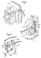
- Figures 1 and 2, respectively, show the fixed and movable parts of a first preferred form of optical connecting means;
- Figure 3 shows the movable connector part and mating body part of second and third preferred forms of optical connecting means and Figures 4 and 5, respectively, show the fixed connector part and mating body part of the second and third preferred forms of optical connecting means;
- Figures 6 and 7, respectively, show the fixed and movable parts of a fourth preferred form of optical connecting means;
- Figures 8 and 9, respectively, show the fixed and movable parts of a fifth preferred form of optical connecting means, and
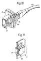
- Figures 10 and 11, respectively, show the fixed and movable parts of a sixth preferred form of optical connecting means.
- In the first preferred form of optical connecting means shown in Figures 1 and 2, one connector part 1 of a two-part plug and socket connector is fixedly secured to a backplane B and the
other connector part 2 of the mechanical connector is movably mounted on a circuit board C. The connector part 1 is of substantially rectangular shape and comprises a peripherally discontinuous shroud 3 defining an opening 4 constituting a socket. Protruding from the end wall 5 of the connector part 1 towards the open mating end of the socket 4 are two rigid pins 6 transversely spaced on opposite sides of the central longitudinal axis of the connector part, the rigid pins and longitudinal axis lying in a common plane. Themovable connector part 2 is disposed between a pair of transverselyspaced guides 7 mounted on the circuit board C and has a pair of oppositely disposed longitudinally extendingflanges 8 which slide loosely within guide channels 9 defined by theguides 7, the extent of such sliding movement being limited by an end wall 10. The relative transverse dimensions of the guide channels 9 andflanges 8 are such that themovable connector part 2 can move to a limited extent with respect to the circuit board C in at least two rectilinear directions normal to the axis of the connector and to one another, i.e. in a direction normal to the major faces of the circuit board and in a direction parallel to the major faces of the circuit board and normal to the axis of the connector. Theguides 7 have a pair of oppositely disposed longitudinally extendingflanges 11 which, together with the adjacent circuit board C, will slidably engage in a pair of slots 12 in oppositely disposed side walls of the shroud 3 of the fixed body part 1. Themovable connector part 2 has opening into its end face two holes 14 which are transversely spaced on opposite sides of the central longitudinal axis of the connector part, the holes and longitudinal axis lying in a common plane, and in which the rigid pins 6 of the fixed connector part 1 will slidably engage when themovable connector part 2 is introduced into the socket 4 constituted by the shroud 3 of the connector part 1 to effect a plug and socket connection. - One
mating body 15 of a two-part plug and socket optical fibre connector is housed in and fixedly secured with respect to the fixed connector part 1 of the mechanical connector with the axes of the connector and the mating body parts parallel to one another; the othermating body part 16 of the optical fibre connector is slidably mounted in a closed bore in themovable connector part 2 of the mechanical connector with its axis parallel to the axis of the movable connector part and is urged by aspring 21 housed in the closed end of the bore in a rectilinear direction parallel to the axes towards the mating end of the movable connector part. Eachmating body part optical fibres optical fibres 17 of thebody part 15 being optically connected tooptical fibres 19 carried by the backplane B and theoptical fibres 18 of thebody part 16 being optically connected tooptical fibres 20 interconnected between devices (not shown) on the circuit board C. Thefixed body part 15 of the optical fibre connector has a pair ofrigid pins 22 protruding from its mating end face parallel to the central longitudinal axis of the fixed body part and disposed on transversely opposite sides of theoptical fibres 17, the pins and optical fibres lying in a common plane; theslidable body part 16 of the optical fibre connector has opening into its mating end face a pair ofholes 23 extending parallel to the central longitudinal axis of the slidable body part and correspondingly transversely disposed on opposite sides of theoptical fibres 18, the holes and optical fibres lying in a common plane. The end faces of thebody parts connector parts 1, 2 of the mechanical connector to reduce risk of damage to the end faces of theoptical fibres - By virtue of the fact that the
movable connector part 2 can move to a limited extent with respect to the circuit board C in a direction normal to the major faces of the circuit board and in a direction parallel to the major faces of the circuit board and normal to the axis of the connector, when an optical connection between a circuit board and the backplane B is to be effected themovable connector part 2 can accommodate any play between the circuit board and the rack in which the circuit board is disposed. Additionally, since thebody part 16 of the optical fibre connector is slidably mounted in theconnector part 2 of the mechanical connector with the axes of these body parts parallel to one another, appropriate limited movement of theconnector part 2 to effect a plug and socket connection with the body part 1 effectively axially aligns thebody parts - In each of the second to sixth preferred forms of optical connecting means to be described with reference to Figures 3 to 11, the form of the two-part plug and socket mechanical connector differs from the form of mechanical connector of each of the other preferred forms of optical connecting means but the forms of the two-part plug and socket optical fibre connectors of these preferred forms of optical connecting means and the manner in which the fixed and slidable mating body parts, respectively of the optical fibre connectors are mounted in the fixed and movable connector parts of the mechanical connectors are substantially identical to the fixed and slidable mating body parts of the optical fibre connector of the first preferred form of optical connecting means and to the manner in which they are mounted within the fixed and
movable connector parts 1, 2 of the mechanical connector as described with respect to and illustrated in Figures 1 and 2. Accordingly, for the sake of brevity and clarity, when describing the preferred forms of optical connecting means shown in Figures 3 to 11, the body parts of the optical fibre connectors thereof will not be described again in detail and, where appropriate, in respect of the optical fibre connectors the same numerical references will be used as those employed in Figures 1 and 2. - Figure 3 illustrates the
movable connector part 32 of the two-part plug and socket mechanical connectors of the second and third preferred forms of optical connecting means. Themovable connector part 32 is of substantially rectangular shape and has a closed bore in which onebody part 16 of a two-part optical fibre connector is slidably mounted and is urged by aspring 21 housed in the closed end of the bore towards the mating end of the movable connector part. Opening into the mating end face of themovable connector part 32 are twoholes 34 which are transversely spaced on opposite sides of the central longitudinal axis of the connector part, the holes and longitudinal axis lying in a common plane. Themovable connector part 32 is resiliently mounted in a recess R in the rear edge of a circuit board C by means of a plurality ofcoil springs 39 mutually spaced on each of two opposite sides of the connector part between the connector part and parts of the circuit board bounding the recess. Thecoil springs 39 provide for movement of themovable connector part 32 to a limited extent with respect to the circuit board C in substantially any direction. - Referring to Figures 3 and 4, the second preferred form of optical connecting means includes a two-part plug and socket mechanical connector of which the
movable connector part 32 is as shown in Figure 3 and thefixed connector part 31 is as shown in Figure 4. Thefixed connector part 31 fixedly secured to a backplane B is of rectangular shape and comprises a peripherallydiscontinuous shroud 33 defining an opening 34 constituting a socket. Abody part 15 of a two-part plug and socket optical fibre connector is fixedly secured in theend wall 35 of theconnector part 31 and in the backplane B. In oppositely disposed side walls of theshroud 33 are twoblind slots 36 for accommodating the circuit board C when themovable connector part 32 shown in Figure 3 effects a plug and socket connection in thefixed connector part 31. - Referring to Figures 3 and 5, the third preferred form of optical connecting means includes a two-part plug and socket mechanical connector of which the
movable connector part 32 is shown in Figure 3 and thefixed connector part 41 is shown in Figure 5. Thefixed connector part 41 fixedly secured to a backplane B is of substantially channel-shape and comprises a base orend wall 45 and oppositely disposedside walls 43. Abody part 15 of a two-part plug and socket optical fibre connector is fixedly secured in thebase 45 and backplane B. Upstanding from thebase 45 into the channel are tworigid pins 46 which are transversely spaced on opposite sides of the central longitudinal axis of thefixed connector part 41, the pins and longitudinal axis lying in a common plane. When themovable connector part 32 is slidably engaged between theside walls 43 of thefixed connector part 41, therigid pins 46 effect plug and socket connections in theholes 34 in the movable connector part. - In each of the second and third preferred forms of optical connecting means, when an optical connection between optical guides associated with the circuit board C and the backplane B is effected, the
movable connector part 32, 42 will accommodate any play between the circuit board and the rack in which the circuit board is disposed whilst effecting a satisfactory optical connection between theoptical fibres body parts - In the fourth preferred form of optical connecting means shown in Figures 6 and 7, the
connector part 51 of the mechanical connector fixedly secured to the backplane B comprises a peripherallydiscontinuous shroud 53 of approximately C-shaped cross-section defining an opening 54 constituting a socket and having, in oppositely disposed side walls of the shroud, a pair of inwardly protrudingguide ribs 56. Themovable connector part 52 has a pair of oppositely disposed longitudinally extendingflanges 58 which slide loosely withinguide channels 59 defined by a pair of transverselyspaced guides 57 mounted on the circuit board C in substantially the same manner as described with respect to the first preferred form of optical connecting means illustrated in Figures 1 and 2. In two oppositely disposed surfaces of theconnector part 52 is a pair ofguide channels 64 into which theguide ribs 56 of thefixed connector part 51 will slidably engage when themovable connector part 52 is introduced into thesocket 54 constituted by theshroud 53 to effect a plug and socket connection. - Referring to Figures 8 and 9, the
connector part 71 of the mechanical connector of the fifth preferred form of optical connecting means fixedly secured to the backplane B comprises a peripherallydiscontinuous shroud 73 of approximately C-shaped cross-section defining an opening 74 constituting a socket and having in the inner surfaces of two oppositely disposed side walls of the shroud a pair ofguide channels 76. Themovable connector part 72 of the mechanical connector has upstanding from two oppositely disposed surfaces a pair ofguide ribs 84 which will slidably engage in theguide channels 76 of theshroud 73 when a plug and socket connection is made between thefixed connector part 71 andmovable connector part 72. Secured to the circuit board C adjacent the oppositely disposed surfaces of themovable connector part 72 from which the guide ribs 84 upstand is a pair of transverselyspaced guides 77 each having an inwardly directed, longitudinally extendingtongue 78 which is a loose sliding fit in agroove 79 in the adjacent of said surfaces of the movable connector part, the groove being closed at each of its ends. The relative transverse dimensions of thetongues 78 andgrooves 79 are such that themovable connector part 72 can move to a limited extent with respect to the circuit board C at least in a direction normal to the major faces of the circuit board and in a direction parallel to the major faces of the circuit board and normal to the axis of the connector. - In the sixth preferred form of optical connecting means shown in Figures 10 and 11, the fixed and
movable connector parts supplementary body 96 is detachably secured to the face of the backplane B remote from the mating end of thefixed connector part 91, the supplementary body having a hole therethrough in axial alignment with a hole in the backplane opening into the fixed connector part, and theassociated body part 15 of the optical fibre connector, optically connected to an end of anoptical cable 100 associated with the backplane, is detachably secured in the hole of the supplementary body so that it protrudes into, and is fixedly secured with respect to, the fixed connector part. - In each of the fourth, fifth and sixth preferred forms of optical connecting means, when an optical connection is made between optical guides associated with the circuit board C and backplane B, any play between the circuit board and the rack in which the circuit board is disposed will be accommodated whilst effecting a satisfactory optical connection between the
optical fibres mating body parts
Claims (17)
- Optical connecting means adapted to effect a disconnectable optical connection between an optical guide carried by or otherwise associated with a circuit board and an optical guide carried by or otherwise associated with a backplane, comprising a mechanical connector having a plug connector part and a socket connector part, the optical connecting means being characterised by, one connector part (2;32;52;72;92;) of the mechanical connector being so mounted on the backplane or on the circuit board (C) that said one connector part can move to a limited extent with respect to the backplane or circuit board in at least two rectilinear directions substantially normal to the connection axis of the connector defined by the direction of insertion of the plug in the socket and the other connector part (1;31;41;51;71;91;) of the mechanical connector being fixedly secured to the circuit board or to the backplane (B) or being so mounted on the circuit board or on the backplane that said other connector part can move to a limited extent with respect to the circuit board or backplane in at least two rectilinear directions substantially normal to the connection axis of the connector; and an optical fibre connector comprising at least two separately formed mating body parts (15,16), each mating body part having at least one substantially flat end face with which an end face of at least one optical fibre (17,18) secured in said mating body part is substantially co-planar, one mating body part (16) of the optical fibre connector being slidably mounted within and with respect to one connector part (2;32;52;72;92) of the mechanical connector with its optical axis substantially parallel to the connection axis of said one connector part of the mechanical connector and with the optical fibre or each of its optical fibres (18) optically connected to or integral with an optical guide (20) carried by or otherwise associated with the circuit board or backplane by which said one connector part of the mechanical connector is carried and being urged by resilient means (21) housed in said one connector part of the mechanical connector in a rectilinear direction substantially parallel to said axes towards the mating end of said connector part of the mechanical connector and the other or another mating body part (15) of the optical fibre connector being housed in and fixedly secured with respect to the other connector part (1;31;41;51;71;91) of the mechanical connector with the axes of said mating and connector parts substantially parallel to one another and with the optical fibre or each of its optical fibres (17) optically connected to or integral with an optical guide (19) carried by or otherwise associated with the backplane or circuit board by which said other connector part of the mechanical connector is carried or being slidably mounted in and with respect to said other connector part of the mechanical connector with its axis substantially parallel to the axis of said other mating body part and with the optical fibre or each of its optical fibres optically connected to or integral with an optical guide carried by or otherwise associated with the backplane or circuit board by which said other connector part of the mechanical connector is carried and being urged by resilient means housed in said other connector part in a rectilinear direction substantially parallel to said axes towards the mating end of said other connector part.
- Optical connecting means as claimed in Claim 1, characterised in that the optical fibre connector is a two-part plug and socket optical fibre connector.
- Optical connecting means as claimed in Claim 2 in which one connector part (1;31;41;51;71;91) of the plug and socket mechanical connector is fixedly secured to a circuit board or to the backplane (B), characterised in that one mating body part (15) of the two-part optical fibre connector is housed in and fixedly secured with respect to the fixed connector part of the mechanical connector.
- Optical connecting means as claimed in Claim 3, characterised in that the fixed connector part (1;31;41;51;71;91) of the plug and socket mechanical connector is fixedly secured to the backplane (B) and the mating body part (15) of the optical fibre connector housed in and fixedly secured with respect to the fixed connector part of the mechanical connector is removable from said fixed connector part of the mechanical connector through a hole in the backplane in a rectilinear direction away from the mating end of said fixed connector part of the mechanical connector.
- Optical connecting means as claimed in Claim 4, characterised in that a supplementary body (96) having a hole therethrough is secured to the face of the backplane (B) remote from the mating end of the fixed connector part (91) of the mechanical connector with its hole in axial alignment with the hole in the backplane, and said mating body part (15) of the optical fibre connector is detachably secured in the hole of said supplementary body and protrudes into said fixed connector part of the mechanical connector.
- Optical connecting means as claimed in any one of Claims 3 to 5, characterised in that the end face of each mating body part (15,16) of the two-part optical fibre connector lies in a plane substantially normal to the axis of the optical fibre connector.
- Optical connecting means as claimed in Claim 6, characterised in that the end face of the mating body part (15) of the optical fibre connector housed in and fixedly secured with respect to the fixed connector part (1;31;41;51;71;91) of the mechanical connector lies in a plane substantially parallel to the major faces of the backplane (B) and the end face of the body part (16) of the optical fibre connector slidably mounted in and with respect to the movable connector part (2;32;52;72;92) of the mechanical connector lies in a plane substantially normal to the major faces of the circuit board (C).
- Optical connecting means as claimed in any one of Claims 3 to 7, characterised in that the fixed mating body part (15) of the optical fibre connector has a pair of substantially rigid pins (22) protruding from its mating end face substantially parallel to the central longitudinal axis of said fixed mating body part and disposed on transversely opposite sides of the optical fibre or optical fibres (17) secured in the fixed body part, the pins and the optical fibre or fibres lying in a substantially common plane, and the mating body part (16) of the optical fibre connector slidably mounted in the movable connector part (2;32;52;72;92) of the mechanical connector has opening into its mating end face a pair of holes (23) extending substantially parallel to the central longitudinal axis of the slidable mating body part and correspondingly transversely spaced on opposite sides of the optical fibre or optical fibres (18) secured in the slidable mating body part, the pins and the optical fibre or fibres lying in a substantially common plane.
- Optical connecting means as claimed in any one of the preceding Claims, characterised in that the end face of one or each mating body part (15,16) of the optical fibre connector is set back from the mating end face of the body part of the mechanical connector in which it is mounted.
- Optical connecting means as claimed in Claim 9, characterised in that the set back end face of the or each mating body part of the optical fibre connector is protected by a spring loaded shutter which must be opened against the action of its spring to permit the body parts of the optical fibre connector to effect a plug and socket connection.
- Optical connecting means as claimed in any one of the preceding Claims, characterised in that the plug and socket connection between the connector parts of the mechanical connector is effected by two substantially rigid pins (6) protruding from the mating end of the fixed connector part (1;41;) of the mechanical connector and transversely spaced on opposite sides of and in substantially the same plane as the central longitudinal axis of said fixed mating body part, which pins will engage in two correspondingly transversely spaced holes (14;34) which open into the mating end face of the movable connector part (2;32) of the mechanical connector and which in use extend substantially parallel to and lie in substantially the same plane as the central longitudinal axis of said movable connector part.
- Optical connecting means as claimed in any one of the preceding Claims, characterised in that the movable connector part (2;32;52;72;92) of the mechanical connector itself effectively constitutes at least a part of a plug which is adapted to engage in a peripherally continuous or discontinuous shroud (3;33;53;73;93) constituting the fixed body part (1;31;51;71;91) of the mechanical connector.
- Optical connecting means as claimed in any one of the preceding Claims, characterised in that the movable connector part (2;52;72;92) of the mechanical connector is slidably mounted between a pair of transversely spaced guides (7;57;77) carried on a major face of the circuit board (C) or on a major face of the backplane, which guides are of such a form as to permit said limited movement of the movable body part in at least said two rectilinear directions.
- Optical connecting means as claimed in Claim 13, characterised in that said transversely spaced guides (7;57) are oppositely disposed longitudinally extending channels (9;59) and the movable body part of the mechanical connector has a pair of oppositely disposed longitudinally extending flanges (8;58) which are slidable within the channels.
- Optical connecting means as claimed in any one of Claims 1 to 12, characterised in that the movable connector part (32) of the mechanical connector is resiliently mounted in a recess (R) in the rear edge of a circuit board (C) by means of a plurality of coil springs (39) or other resilient devices mutually spaced at intervals around a part of the periphery of the body part between the body part and parts of the circuit board bounding the recess.
- Optical connecting means as claimed in any one of the preceding Claims, characterised in that the two-part plug and socket mechanical connector additionally constitutes an edge connector for effecting interconnection between electric circuits of a circuit board and electric circuits of the backplane.
- Optical connecting means as claimed in Claim 16, characterised in that the plug and socket connection between the two connector parts of the mechanical connector is constituted by a plurality of substantially rigid electric contact pins in one body part which will effect electrical connection in a plurality of similarly disposed plated through holes or other electrically conductive sockets in the other body part of the mechanical connector.
Applications Claiming Priority (6)
| Application Number | Priority Date | Filing Date | Title |
|---|---|---|---|
| GB9024178 | 1990-11-07 | ||
| GB909024178A GB9024178D0 (en) | 1990-11-07 | 1990-11-07 | Optical connection to backplanes |
| GB9113064 | 1991-06-18 | ||
| GB919113064A GB9113064D0 (en) | 1991-06-18 | 1991-06-18 | Optical connection to backplanes |
| GB9113065 | 1991-06-18 | ||
| GB919113065A GB9113065D0 (en) | 1991-06-18 | 1991-06-18 | Optical connection to backplanes |
Publications (3)
| Publication Number | Publication Date |
|---|---|
| EP0485196A2 EP0485196A2 (en) | 1992-05-13 |
| EP0485196A3 EP0485196A3 (en) | 1992-09-30 |
| EP0485196B1 true EP0485196B1 (en) | 1994-12-14 |
Family
ID=27265361
Family Applications (1)
| Application Number | Title | Priority Date | Filing Date |
|---|---|---|---|
| EP91310269A Revoked EP0485196B1 (en) | 1990-11-07 | 1991-11-06 | Optical connection to backplanes |
Country Status (13)
| Country | Link |
|---|---|
| US (1) | US5155784A (en) |
| EP (1) | EP0485196B1 (en) |
| JP (1) | JPH0560939A (en) |
| KR (1) | KR920010996A (en) |
| AU (1) | AU654683B2 (en) |
| CA (1) | CA2055027A1 (en) |
| CS (1) | CS338691A3 (en) |
| DE (1) | DE69105922T2 (en) |
| GB (1) | GB2251090B (en) |
| HK (1) | HK87395A (en) |
| HU (1) | HUT60041A (en) |
| MX (1) | MX9101970A (en) |
| MY (1) | MY136243A (en) |
Cited By (3)
| Publication number | Priority date | Publication date | Assignee | Title |
|---|---|---|---|---|
| DE19539549C1 (en) * | 1995-10-12 | 1996-12-05 | Siemens Ag | Optical connector arrangement for electronic devices |
| DE19728960C1 (en) * | 1997-06-30 | 2000-07-06 | Siemens Ag | Optical multiple connector |
| US6116788A (en) * | 1996-10-11 | 2000-09-12 | Siemens Aktiengesellschaft | Optical plug connector |
Families Citing this family (69)
| Publication number | Priority date | Publication date | Assignee | Title |
|---|---|---|---|---|
| FR2682194B1 (en) * | 1991-10-08 | 1994-11-18 | Thomson Csf | OPTICAL INTERCONNECTION RULE. |
| US5325455A (en) * | 1992-10-21 | 1994-06-28 | Minnesota Mining And Manufacturing Company | Fiber optic edge card connector |
| NL9202172A (en) * | 1992-12-16 | 1994-07-18 | Framatome Connectors Belgium | Connector assembly. |
| US5280551A (en) * | 1992-12-23 | 1994-01-18 | At&T Bell Laboratories | Backplane optical spine |
| EP0860721B1 (en) * | 1993-03-31 | 2002-06-26 | Sumitomo Electric Industries, Ltd. | Optical fiber array and method of manufacturing |
| US5420954A (en) * | 1993-05-24 | 1995-05-30 | Photonics Research Incorporated | Parallel optical interconnect |
| US6004147A (en) * | 1993-09-02 | 1999-12-21 | State Of Israel, Ministry Of Defence, Etc. | Line terminal particularly signal transmitter, connector assembly |
| IL106876A (en) * | 1993-09-02 | 1995-10-31 | Israel State | Signal transmitter connector assembly |
| GB9320984D0 (en) * | 1993-10-12 | 1993-12-01 | Fujitsu Ltd | Rack-mounting opto-electronic equipment |
| FR2719389B1 (en) * | 1994-04-27 | 1996-07-05 | Radiall Sa | Fiber optic connector. |
| SE9402082L (en) * | 1994-06-14 | 1995-12-15 | Ericsson Telefon Ab L M | Miniature optical capsule |
| US5530783A (en) * | 1994-08-31 | 1996-06-25 | Berg Technology, Inc. | Backplane optical fiber connector for engaging boards of different thicknesses and method of use |
| US5631807A (en) * | 1995-01-20 | 1997-05-20 | Minnesota Mining And Manufacturing Company | Electronic circuit structure with aperture suspended component |
| US6045270A (en) * | 1995-12-22 | 2000-04-04 | Methode Electronics, Inc. | Massive parallel optical interconnect system |
| US5737463A (en) * | 1995-12-22 | 1998-04-07 | Weiss; Roger E. | Massive parallel optical interconnect system |
| DE59705771D1 (en) * | 1996-03-12 | 2002-01-24 | Diamond Sa | Device for connecting fiber optic cables in pairs with a plurality of optical fibers arranged in parallel |
| US5920670A (en) * | 1996-06-07 | 1999-07-06 | 3M Innovative Properties Company | Multiple alignment connector ferrule |
| US5823815A (en) * | 1996-04-02 | 1998-10-20 | Harness System Technologies Research, Ltd. | Structure of interconnecting units with respective connectors |
| US6095695A (en) * | 1996-10-28 | 2000-08-01 | Sumitomo Electric Industries, Ltd. | Optical connector, and using method and tool thereof |
| US5778121A (en) * | 1996-11-05 | 1998-07-07 | Itt Corporation | Connector with optic fiber terminal |
| JP4215831B2 (en) | 1997-06-24 | 2009-01-28 | シーメンス エレクトロメカニカル コンポーネンツ ゲゼルシャフト ミット ベシュレンクテル ハフツング ウント コンパニー コマンディートゲゼルシャフト | Connector connecting device for releasably connecting an optical waveguide to another optical waveguide |
| US6370145B1 (en) * | 1997-08-22 | 2002-04-09 | Avici Systems | Internet switch router |
| US6285679B1 (en) | 1997-08-22 | 2001-09-04 | Avici Systems, Inc. | Methods and apparatus for event-driven routing |
| US6205532B1 (en) | 1998-05-22 | 2001-03-20 | Avici Systems, Inc. | Apparatus and methods for connecting modules using remote switching |
| DE19934727B4 (en) * | 1999-07-23 | 2005-02-17 | Tyco Electronics Logistics Ag | Optical plug connection device |
| US6302590B1 (en) | 1999-09-03 | 2001-10-16 | Picolight Incorporated | Enclosure for optical subassembly having mechanical alignment features |
| US6485192B1 (en) * | 1999-10-15 | 2002-11-26 | Tyco Electronics Corporation | Optical device having an integral array interface |
| US7076144B2 (en) * | 1999-12-01 | 2006-07-11 | 3M Innovative Properties Company | Apparatus and method for controlling the bend radius of an optical fiber cable |
| US6789950B1 (en) | 1999-12-01 | 2004-09-14 | 3M Innovative Properties Company | Optical fiber connector system |
| US6419399B1 (en) * | 1999-12-01 | 2002-07-16 | 3M Innovative Properties Company | Optical fiber connector system |
| DE10001680C1 (en) | 2000-01-12 | 2001-08-23 | Infineon Technologies Ag | Multi-channel optical coupling arrangement |
| DE10021251A1 (en) | 2000-04-22 | 2001-10-25 | Francotyp Postalia Gmbh | Arrangement for an optical device interface |
| US6390690B1 (en) * | 2000-05-17 | 2002-05-21 | 3M Innovative Properties Company | Fiber optic connector for coupling devices on intersecting planes |
| US6682230B1 (en) * | 2000-08-09 | 2004-01-27 | Berg Technology, Inc. | Optical connector and printed circuit board assembly with movable connection |
| US7010232B1 (en) * | 2000-12-20 | 2006-03-07 | Cisco Technology, Inc. | Removable optical interface modules |
| US6863444B2 (en) | 2000-12-26 | 2005-03-08 | Emcore Corporation | Housing and mounting structure |
| US6867377B2 (en) | 2000-12-26 | 2005-03-15 | Emcore Corporation | Apparatus and method of using flexible printed circuit board in optical transceiver device |
| US6799902B2 (en) | 2000-12-26 | 2004-10-05 | Emcore Corporation | Optoelectronic mounting structure |
| US7021836B2 (en) | 2000-12-26 | 2006-04-04 | Emcore Corporation | Attenuator and conditioner |
| US6905260B2 (en) | 2000-12-26 | 2005-06-14 | Emcore Corporation | Method and apparatus for coupling optical elements to optoelectronic devices for manufacturing optical transceiver modules |
| US7061944B2 (en) | 2001-05-25 | 2006-06-13 | International Business Machines Corporation | Apparatus and method for wavelength-locked loops for systems and applications employing electromagnetic signals |
| US6751014B2 (en) | 2001-06-19 | 2004-06-15 | International Business Machines Corporation | Automatic gain control and dynamic equalization of erbium doped optical amplifiers in wavelength multiplexing networks |
| US7062166B2 (en) | 2001-09-26 | 2006-06-13 | International Business Machines Corporation | First and second derivative processing of wavelength multiplexed optical signals |
| US6970649B2 (en) * | 2001-10-30 | 2005-11-29 | International Business Machines Corporation | WDMA free space broadcast technique for optical backplanes and interplanar communications |
| US6893167B1 (en) * | 2002-01-17 | 2005-05-17 | Opnext, Inc. | Mountable optical transceiver |
| US6863453B2 (en) | 2003-01-28 | 2005-03-08 | Emcore Corporation | Method and apparatus for parallel optical transceiver module assembly |
| JP2005181959A (en) * | 2003-12-22 | 2005-07-07 | Rohm & Haas Electronic Materials Llc | Method and structure for coupling optical fiber with printed wiring board embedded waveguide |
| NL1025379C2 (en) * | 2004-02-02 | 2005-08-03 | Framatome Connectors Int | Optical connector system. |
| NL1025381C2 (en) | 2004-02-02 | 2005-08-03 | Framatome Connectors Int | Optical connector system. |
| US7217040B2 (en) * | 2004-09-30 | 2007-05-15 | Intel Corporation | Blind mate optical connector |
| GB2426831B (en) * | 2005-06-01 | 2007-04-25 | Xyratex Tech Ltd | An optical connector, a communication system and a method of connecting a user circuit to an optical backplane |
| DE102005029293A1 (en) | 2005-06-22 | 2007-01-11 | Thomson Broadcast And Media Solutions Gmbh | Device for mechanical and electrical connection |
| TWM294038U (en) * | 2006-01-20 | 2006-07-11 | Advanced Connectek Inc | Optical fiber connector |
| JP5311570B2 (en) | 2009-05-26 | 2013-10-09 | 日本航空電子工業株式会社 | Optical connector device and counterpart optical connector device |
| ES2398782T3 (en) * | 2009-09-03 | 2013-03-21 | Tyco Electronics Raychem Bvba | Fiber optic connector assembly and fiber termination unit |
| CN102576130B (en) | 2009-12-21 | 2014-04-09 | 惠普发展公司,有限责任合伙企业 | Circuit switched optical interconnection fabric |
| WO2011084155A1 (en) | 2010-01-06 | 2011-07-14 | Hewlett-Packard Development Company, L.P. | Optical interconnect |
| WO2011116159A1 (en) * | 2010-03-19 | 2011-09-22 | Corning Incorporated | Fiber optic interface device with bent optical path |
| JP2013522689A (en) * | 2010-03-19 | 2013-06-13 | コーニング インコーポレイテッド | Small form factor fiber optic interface assembly for electronic devices |
| ITMI20101692A1 (en) * | 2010-09-17 | 2012-03-18 | Compel Electronics S P A | OPTICAL INTERCONNECTION EQUIPMENT |
| FR2966609B1 (en) * | 2010-10-22 | 2012-12-14 | Radiall Sa | OPTICAL CONTACT, MULTICONTACT CONNECTOR AND METHOD FOR CONNECTING TWO OPTICAL CONTACTS |
| CN102866465A (en) * | 2011-07-05 | 2013-01-09 | 富士康(昆山)电脑接插件有限公司 | Optical connection assembly and photoelectric connector with same |
| JP2013257430A (en) * | 2012-06-12 | 2013-12-26 | Sumitomo Electric Ind Ltd | Optical and electric composite connector connection structure and optical and electric composite connector |
| US9182555B2 (en) | 2012-06-26 | 2015-11-10 | Japan Aviation Electronics Industry, Limited | Backplane optical connector |
| TW201409102A (en) * | 2012-08-29 | 2014-03-01 | Hon Hai Prec Ind Co Ltd | Optical fiber connector |
| US9529162B2 (en) | 2012-10-09 | 2016-12-27 | Corning Optical Communications LLC | Optical fiber connectors and methods of forming optical fiber connectors |
| US9086546B2 (en) * | 2012-11-29 | 2015-07-21 | Corning Cable Systems Llc | Connector systems having receptacle assembly and plug assembly |
| JP6021619B2 (en) * | 2012-12-05 | 2016-11-09 | 富士通コンポーネント株式会社 | Optical connector, optical connector system, optical backplane device |
| US9645327B2 (en) | 2014-06-09 | 2017-05-09 | Corning Optical Communications LLC | Side-facet coupler having external mounting surface molded to facilitate alignment of optical connections |
Family Cites Families (19)
| Publication number | Priority date | Publication date | Assignee | Title |
|---|---|---|---|---|
| NL7802231A (en) * | 1978-03-01 | 1979-09-04 | Tekade Felten & Guilleaume | CONTRAST PLUG WITH A LIGHT DETECTOR FOR A REMOVABLE PLUG CONNECTION FOR COUPLING A LIGHT-CONDUCTING FIBER TO A SEMICONDUCTOR LIGHT SOURCE. |
| FR2435057A1 (en) * | 1978-09-01 | 1980-03-28 | Thomson Csf | OPTICAL CONNECTOR FOR PRINTED CIRCUIT BOARD |
| DE2907705C2 (en) * | 1979-02-28 | 1984-10-11 | Schaltbau GmbH, 8000 München | Device for pressing an optical waveguide onto a photoelectric component |
| US4645295A (en) * | 1980-02-04 | 1987-02-24 | Allied Corporation | Fiber optic connector |
| US4406514A (en) * | 1980-03-26 | 1983-09-27 | Harris Corporation | Single fiber connector for pluggable card or module optical interconnections |
| US4470660A (en) * | 1981-08-28 | 1984-09-11 | Harris Corporation | Blind mating rack and panel fiber optic connector |
| US4432604A (en) * | 1982-04-28 | 1984-02-21 | Bell Telephone Laboratories, Incorporated | Self-adjusting fiberoptic connector assembly |
| FR2529349A1 (en) * | 1982-06-25 | 1983-12-30 | Souriau & Cie | OPTICAL FIBER CONNECTOR FOR SLIDING SUPPORT IN A ROCKER CABINET |
| US4597631A (en) * | 1982-12-02 | 1986-07-01 | The United States Of America As Represented By The Secretary Of The Navy | Printed circuit card hybrid |
| FR2562271B1 (en) * | 1984-03-29 | 1986-07-18 | Telecommunications Sa | CONNECTOR OF AN OPTICAL FIBER AND A PHOTO-ELEMENT, RECEIVER OR TRANSMITTER, AND POSITIONING METHOD THEREOF |
| US4840451A (en) * | 1987-12-08 | 1989-06-20 | Molex Incorporated | Shielded fiber optic connector assembly |
| EP0330231B1 (en) * | 1988-02-26 | 1995-05-10 | Nippon Telegraph And Telephone Corporation | Plug-in connector |
| US4881792A (en) * | 1988-03-31 | 1989-11-21 | American Telephone And Telegraph Company, At&T Bell Laboratories | Self-adjusting optical fiber connector assembly |
| US4863233A (en) * | 1988-05-12 | 1989-09-05 | Zenith Electronics Corporation | Fiber optic interconnect system |
| CA1312756C (en) * | 1988-06-15 | 1993-01-19 | Peter Tjing Hak Kwa | Optical connector |
| US4863232A (en) * | 1988-06-16 | 1989-09-05 | Northern Telecom Limited | Optical connector |
| US4993803A (en) * | 1989-05-18 | 1991-02-19 | General Motors Corporation | Electro-optical header connector |
| DE9001866U1 (en) * | 1990-02-16 | 1990-06-13 | Siemens Ag, 1000 Berlin Und 8000 Muenchen, De | |
| US5042891A (en) * | 1990-06-21 | 1991-08-27 | Amp Incorporated | Active device mount assembly with interface mount for push-pull coupling type optical fiber connectors |
-
1991
- 1991-10-30 US US07/784,969 patent/US5155784A/en not_active Expired - Fee Related
- 1991-10-30 AU AU86874/91A patent/AU654683B2/en not_active Ceased
- 1991-11-05 HU HU913473A patent/HUT60041A/en unknown
- 1991-11-06 MY MYPI91002049A patent/MY136243A/en unknown
- 1991-11-06 CA CA002055027A patent/CA2055027A1/en not_active Abandoned
- 1991-11-06 GB GB9123602A patent/GB2251090B/en not_active Expired - Lifetime
- 1991-11-06 EP EP91310269A patent/EP0485196B1/en not_active Revoked
- 1991-11-06 DE DE69105922T patent/DE69105922T2/en not_active Revoked
- 1991-11-07 KR KR1019910019700A patent/KR920010996A/en not_active Application Discontinuation
- 1991-11-07 JP JP3318575A patent/JPH0560939A/en active Pending
- 1991-11-07 MX MX9101970A patent/MX9101970A/en unknown
- 1991-11-07 CS CS913386A patent/CS338691A3/en unknown
-
1995
- 1995-06-01 HK HK87395A patent/HK87395A/en unknown
Cited By (4)
| Publication number | Priority date | Publication date | Assignee | Title |
|---|---|---|---|---|
| DE19539549C1 (en) * | 1995-10-12 | 1996-12-05 | Siemens Ag | Optical connector arrangement for electronic devices |
| US6116788A (en) * | 1996-10-11 | 2000-09-12 | Siemens Aktiengesellschaft | Optical plug connector |
| DE19728960C1 (en) * | 1997-06-30 | 2000-07-06 | Siemens Ag | Optical multiple connector |
| US6146023A (en) * | 1997-06-30 | 2000-11-14 | Infineon Technologies Ag | Optical multi-connector |
Also Published As
| Publication number | Publication date |
|---|---|
| HUT60041A (en) | 1992-07-28 |
| GB2251090B (en) | 1994-03-30 |
| EP0485196A3 (en) | 1992-09-30 |
| CS338691A3 (en) | 1992-10-14 |
| DE69105922T2 (en) | 1995-05-04 |
| JPH0560939A (en) | 1993-03-12 |
| DE69105922D1 (en) | 1995-01-26 |
| MX9101970A (en) | 1992-07-08 |
| HU913473D0 (en) | 1992-02-28 |
| US5155784A (en) | 1992-10-13 |
| KR920010996A (en) | 1992-06-27 |
| AU8687491A (en) | 1992-05-14 |
| HK87395A (en) | 1995-06-09 |
| EP0485196A2 (en) | 1992-05-13 |
| GB9123602D0 (en) | 1992-01-02 |
| MY136243A (en) | 2008-08-29 |
| GB2251090A (en) | 1992-06-24 |
| AU654683B2 (en) | 1994-11-17 |
| CA2055027A1 (en) | 1992-05-08 |
Similar Documents
| Publication | Publication Date | Title |
|---|---|---|
| EP0485196B1 (en) | Optical connection to backplanes | |
| US5046960A (en) | High density connector system | |
| US6234817B1 (en) | Blind-mate, floatable connectors assembly | |
| US9209539B2 (en) | Backplane or midplane communication system and connector | |
| US5216732A (en) | Optical fiber guide connection | |
| EP2169773B1 (en) | Assembly for interconnecting circuit boards | |
| US6682230B1 (en) | Optical connector and printed circuit board assembly with movable connection | |
| US6672878B2 (en) | Actuatable connector system | |
| EP0561642B1 (en) | Electrical connector | |
| US6513989B1 (en) | Ferrule container for holding a multiple optical fiber disposed in a ferrule, and a connector for connecting multiple optical fibers | |
| TWI620381B (en) | Cable connector assembly | |
| US5055061A (en) | Circuit card guide | |
| US9160088B2 (en) | Backplane communication system and rack assembly of the same | |
| JP3545023B2 (en) | Connector device | |
| US6984073B2 (en) | Optical and opto-electronic interconnect alignment system | |
| EP3790117A1 (en) | Electrical connector assembly | |
| WO1994019844A1 (en) | Circuit card interface system | |
| US9590366B1 (en) | Cable assembly and communication system configured to receive the cable assembly | |
| US10230203B2 (en) | Cable tray assembly | |
| EP0251515B1 (en) | Hingeable electrical connector assembly | |
| US20110170828A1 (en) | Connectors and assemblies having a plurality of moveable mating arrays | |
| US7632140B2 (en) | Card connector | |
| US9356381B2 (en) | Protective cover configured to cover a mating interface of an electrical connector | |
| US20080298751A1 (en) | Shelf-card assembly for optic fiber connection | |
| CN110611188B (en) | Floating type connecting module and floating type butt joint device with same |
Legal Events
| Date | Code | Title | Description |
|---|---|---|---|
| PUAI | Public reference made under article 153(3) epc to a published international application that has entered the european phase |
Free format text: ORIGINAL CODE: 0009012 |
|
| AK | Designated contracting states |
Kind code of ref document: A2 Designated state(s): DE GB IT SE |
|
| 17P | Request for examination filed |
Effective date: 19920422 |
|
| PUAL | Search report despatched |
Free format text: ORIGINAL CODE: 0009013 |
|
| AK | Designated contracting states |
Kind code of ref document: A3 Designated state(s): DE GB IT SE |
|
| 17Q | First examination report despatched |
Effective date: 19930721 |
|
| RBV | Designated contracting states (corrected) |
Designated state(s): DE IT SE |
|
| GRAA | (expected) grant |
Free format text: ORIGINAL CODE: 0009210 |
|
| AK | Designated contracting states |
Kind code of ref document: B1 Designated state(s): DE IT SE |
|
| REF | Corresponds to: |
Ref document number: 69105922 Country of ref document: DE Date of ref document: 19950126 |
|
| EAL | Se: european patent in force in sweden |
Ref document number: 91310269.5 |
|
| ITF | It: translation for a ep patent filed |
Owner name: SOCIETA' ITALIANA BREVETTI S.P.A. |
|
| PLBI | Opposition filed |
Free format text: ORIGINAL CODE: 0009260 |
|
| PLBI | Opposition filed |
Free format text: ORIGINAL CODE: 0009260 |
|
| PGFP | Annual fee paid to national office [announced via postgrant information from national office to epo] |
Ref country code: SE Payment date: 19951013 Year of fee payment: 5 |
|
| PGFP | Annual fee paid to national office [announced via postgrant information from national office to epo] |
Ref country code: DE Payment date: 19951023 Year of fee payment: 5 |
|
| 26 | Opposition filed |
Opponent name: THE WHITAKER CORPORATION Effective date: 19950906 |
|
| 26 | Opposition filed |
Opponent name: SIEMENS AG Effective date: 19950914 Opponent name: THE WHITAKER CORPORATION Effective date: 19950906 |
|
| PLAB | Opposition data, opponent's data or that of the opponent's representative modified |
Free format text: ORIGINAL CODE: 0009299OPPO |
|
| R26 | Opposition filed (corrected) |
Opponent name: THE WHITAKER CORPORATION * 950913 SIEMENS AG Effective date: 19950906 |
|
| PLBF | Reply of patent proprietor to notice(s) of opposition |
Free format text: ORIGINAL CODE: EPIDOS OBSO |
|
| RDAG | Patent revoked |
Free format text: ORIGINAL CODE: 0009271 |
|
| STAA | Information on the status of an ep patent application or granted ep patent |
Free format text: STATUS: PATENT REVOKED |
|
| 27W | Patent revoked |
Effective date: 19960624 |