EP0492263A1 - Magnetometer probe for measuring of magnetic fields arising from the activity of the brain - Google Patents
Magnetometer probe for measuring of magnetic fields arising from the activity of the brain Download PDFInfo
- Publication number
- EP0492263A1 EP0492263A1 EP91121131A EP91121131A EP0492263A1 EP 0492263 A1 EP0492263 A1 EP 0492263A1 EP 91121131 A EP91121131 A EP 91121131A EP 91121131 A EP91121131 A EP 91121131A EP 0492263 A1 EP0492263 A1 EP 0492263A1
- Authority
- EP
- European Patent Office
- Prior art keywords
- dewar
- spring
- support structure
- magnetometer
- spheres
- Prior art date
- Legal status (The legal status is an assumption and is not a legal conclusion. Google has not performed a legal analysis and makes no representation as to the accuracy of the status listed.)
- Granted
Links
Images


Classifications
-
- A—HUMAN NECESSITIES
- A61—MEDICAL OR VETERINARY SCIENCE; HYGIENE
- A61B—DIAGNOSIS; SURGERY; IDENTIFICATION
- A61B5/00—Measuring for diagnostic purposes; Identification of persons
- A61B5/24—Detecting, measuring or recording bioelectric or biomagnetic signals of the body or parts thereof
- A61B5/242—Detecting biomagnetic fields, e.g. magnetic fields produced by bioelectric currents
- A61B5/245—Detecting biomagnetic fields, e.g. magnetic fields produced by bioelectric currents specially adapted for magnetoencephalographic [MEG] signals
-
- Y—GENERAL TAGGING OF NEW TECHNOLOGICAL DEVELOPMENTS; GENERAL TAGGING OF CROSS-SECTIONAL TECHNOLOGIES SPANNING OVER SEVERAL SECTIONS OF THE IPC; TECHNICAL SUBJECTS COVERED BY FORMER USPC CROSS-REFERENCE ART COLLECTIONS [XRACs] AND DIGESTS
- Y10—TECHNICAL SUBJECTS COVERED BY FORMER USPC
- Y10S—TECHNICAL SUBJECTS COVERED BY FORMER USPC CROSS-REFERENCE ART COLLECTIONS [XRACs] AND DIGESTS
- Y10S505/00—Superconductor technology: apparatus, material, process
- Y10S505/825—Apparatus per se, device per se, or process of making or operating same
- Y10S505/842—Measuring and testing
- Y10S505/843—Electrical
- Y10S505/845—Magnetometer
- Y10S505/846—Magnetometer using superconductive quantum interference device, i.e. squid
Definitions
- This invention relates to a compact magnetometer element comprising of fiber glass and superconducting thin-film components on silicon, and a support structure used for integration of the individual magnetometer elements into a detector array applicable to magnetoencephalographic (MEG) recordings of human brain activity.
- MEG magnetoencephalographic
- Such devices are used for recording the weak, space and time dependent magnetic fields arising from neural activity. In medical research and diagnostics these methods are gaining more and more attention. Especially, the study of the brain function and malfunction in man can be done noninvasively with this method, i.e. without touching the subject or exposing him to electromagnetic radiation or radioactive tracers.
- EEG electroencephalographic
- the present invention is directed to a SQUID magnetometer element having a novel type of mechanical construction, and a support structure to be used in a helium dewar for integration of the individual magnetometer elements into an array that covers the entire cranium of a human subject.
- MEG devices collecting practically all the information available through the method, have not been constructed so far.
- a magnetometer insert on which the individual magnetometer elements and their support structure described here can be mounted is described in a co-pending patent application "A multichannel device for measurement of weak spatially and temporally varying magnetic fields" by Ahonen, Knuutila, Simola, and Vilkman, serial number
- the magnetometer element In constructing the magnetometer element one must be able to join together the substrate of the thin film SQUID, a piece of thin silicon wafer about one inch in diameter, and a base element made of insulating material and containing the electrical contacts and the structures needed for mechanical mounting of the magnetometer element on the support structure.
- the joint between the silicon and the base element must sustain the repeated thermal cycling between room temperature and the liquid helium temperature during the testing and maintenance of the magnetometer. Because of the relatively low thermal expansion of silicon such a joint made by gluing is not reliable. It is also impossible to mount commercially available connectors directly and reliably on silicon.
- the signal coil on the magnetometer element must be located as close to the bottom of the helium dewar as possible and the element itself must be flat.
- the first requirement arises from the need to minimize the distance between the detector coil and the source for the magnetic field located in the brain outside the dewar. This is necessary because the amplitude of the measured signal is inversely proportional to the third power of the distance from the source. The latter requirement is explained by the need to minimize the diameter of the neck through which the magnetometer array is introduced into the dewar. This minimizes the boil off rate of liquid helium which is an essential problem in the construction of dewars for MEG magnetometers. To cover the whole skull one must place magnetometer channels on opposite sides of the skull.
- the minimum inner diameter of the dewar neck is therefore approximately 25 centimeters added with the heights of the two magnetometer elements on opposite sides of the head.
- the height of the magnetometer elements along with the structures needed for their mounting has been several centimeters.
- the boil off rate in dewars with such wide necks is dominated by the conduction of heat along the neck, and reducing the diameter of the required neck, i.e. the height of the magnetometer elements, is therefore crucial.
- the central goal in both scientific and clinical use of MEG devices is to locate the cortical source currents responsible for the measured neuromagnetic field as accurately as possible. This goal can be achieved only if 1) the field is measured over the entire cortex and if 2) the geometry of the measuring device and its location with respect to the brain is known accurately.
- To cover the appropriate parts of the skull one needs a support structure for the magnetometer array which is roughly hemispherical in shape.
- the diameter of the hemisphere should be about 25 cm and the accuracy of its overall geometry better than a millimeter which roughly corresponds to the relevant accuracy in locating neurological current sources.
- the magnetometer structure described in this invention solves the problems associated with the fabrication of a whole cortex MEG device.
- the main problems, as described above, are associated with 1) integration of the silicon substrate with insulating base materials in a way resistant to repeated thermal cycling, 2) minimizing the diameter of the dewar neck necessary for insertion of a whole cortex detector array, and 3) accuracy of the overall geometry of the magnetometer array at liquid helium temperature.
- the base for mounting the silicon chip is a piece of printed circuit board made of fiber glass. The silicon is held in place by a glass fiber spring cut in the edge of the printed circuit board. No glue joint breaking easily in thermal cycling is needed.
- the signal coils on silicon are planar and the height of the magnetometer element (orthogonal to the plane of the coil) is less than a centimeter. Consequently, the diameter of the dewar neck does not essentially exceed the 25 centimeters necessary for whole cortex coverage of an average human skull.
- the support structure that integrates the individual magnetometer channels into an array covering the whole skull consists of a single shell made of glass fiber. The holes for mounting all the channels on this shell are machined on the blank shell without detaching it from the machine. This ensures that the relative location of channels even on opposite sides of the skull is accurate.
- Each individual channel element is mounted on the support structure elastically so that its final orientation with respect to the bottom of the dewar is determined by the three feet on the element leaning toward the bottom.
- the lower end of the magnetometer described in this invention is thus so constructed that the final geometry of the channel array is determined by the support structure and the bottom of the dewar together.
- the yielding of the spring must prevent the feet of individual channel elements from pressing against the bottom of the dewar too strongly.
- the location and orientation of an individual channel element is governed by six degrees of freedom, corresponding to three translational and three rotational coordinates.
- the translations are described in terms of the spherical coordinate system defined by the spherical bottom of the dewar.
- the signal coil When the signal coil is leaning on its three feet and oriented tangentially to the bottom it can be rotated into any position determined by the azimuthal ( ⁇ ) or polar ( ) angles or rotated around its own normal into an arbitrary orientation ( ⁇ ) without lifting the feet off from the spherical bottom surface. This means that motions along these degrees of freedom do not affect the force exerted on the bottom by the feet.
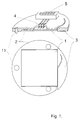
- Figure 1 illustrates a magnetometer element integrated from a thin silicon wafer and a fiber glass plate.
- Figure 2 shows the magnetometer support structure in its final place on a hemispherical bottom of the dewar.
- Figure 3 is a planar fiber glass spring used for mounting an individual channel element elastically on the support structure, and
- Figure 4 shows an example of the proper shape for the bottom of a MEG dewar providing whole cortex coverage. This geometry is completely characterized by four parameters.
- the silicon plate (1) carrying the SQUID and the planar signal coil made by thin film technique is mounted face to face with the base element (2) consisting of a piece of printed circuit board (fiber glass).
- a strung spring (3) cut in the edge of the printed circuit board holds the silicon element in place by exerting a compressive force in the plane of the silicon element.
- Each silicon element may carry either one or several signal coils wound to measure magnetic flux (magnetometer) or gradients of the flux (gradiometer), and the SQUIDs necessary for reading these coils.
- the electrical contacts (4) needed between the thin film components on silicon (1) and the printed circuit board (2) are made by using conventional microcircuit bonding techniques.
- the printed circuit board (2) is provided with small connectors (5) which take care of the necessary electrical connections as well. These connectors involve no superconducting contacts since both the SQUID and the signal coil are on the same channel element.
- the connectors (5) must be mounted on the base element (2) in such a way that when they are pressed against their counterparts (6) the channel element assumes a mechanically well defined and accurate position with respect to the magnetometer support structure (7).
- the magnetometer support structure, in Figure 2, on which the individual magnetometer channels shown in Figure 1 are attached is fabricated from a single glass fiber shell (7) molded to follow the shape of the bottom of the dewar. When inserted into the dewar the glass fiber shell settles toward the bottom (10) in a well defined position and orientation so that the gap (8) between the bottom and the shell is uniform.
- the counter connectors (6) on which the individual channel elements (Fig. 1) attach are fastened on the glass fiber shell (7) via elastic springs (Fig. 3) so that the channel elements together form a uniform array covering the whole skull.
- the support structure equipped with the magnetometer channels is in its final place in the dewar the channel elements are pressed by the glass fiber springs against the bottom of the dewar (10).
- the channel elements are provided with three feet (11) reaching beyond the silicon wafer (1), thus preventing the silicon from touching the bottom of the dewar.
- these feet keep the signal coils on the silicon wafer in tangential orientation and one millimeter apart from the bottom.
- a simple glass fiber spring (9) that works in the desired way and takes a small volume is shown in Figure 3.
- a thin, square shaped glass fiber plate (12) is opened by four cuts (13) in such a way that the center part of the plate (14) is able to rotate around two axes ( ⁇ and ⁇ ) in the plane of the plate and is able to come out from the plane of the plate (r).
- a piece of glass fiber (16, Fig. 2) carrying the counter connectors (6, Fig. 2) for mounting the channel element is fixed on the center part of the spring in a mechanically well defined way (by two screws).
- the outer edge of the spring is mounted on the support structure (7, Fig. 2) by screwing the spring on a normal plane (17, Fig.
- An ordinary cylindrical helium dewar is provided with a bottom determined by 1) two nonconcentric spheres (19,20) with different radii, 2) the conical surface (21) tangent to both spheres, and 3) the vertical cylindrical surface (23) tangential to the spheres and the cone.
- the continuous bottom surface consists of two spherical sections limited between the osculation curves of the spheres with the cone and the cylinder, and of the section of the conical surface left between its osculation circles with the spheres.
- the vertical cylindrical surface (23) reaches low enough to cover the entire cortex on the occipital side of the head but leaves the eyes uncovered to allow visual stimulation of the subject.
Abstract
Description
- This invention relates to a compact magnetometer element comprising of fiber glass and superconducting thin-film components on silicon, and a support structure used for integration of the individual magnetometer elements into a detector array applicable to magnetoencephalographic (MEG) recordings of human brain activity. Such devices are used for recording the weak, space and time dependent magnetic fields arising from neural activity. In medical research and diagnostics these methods are gaining more and more attention. Especially, the study of the brain function and malfunction in man can be done noninvasively with this method, i.e. without touching the subject or exposing him to electromagnetic radiation or radioactive tracers. The essential advantage of the MEG method as compared to the widely used electroencephalographic (EEG) method, i.e. measurement of the electric potential on the scalp, is due to the fact that the nonuniform conductivity of the human tissue distorts the magnetic signals of neural origin much less than the associated electric potential distributions on the scalp. Consequently, by the MEG method it is possible to locate the source currents associated with the brain activities with a spatial and temporal resolution of a few millimeters and milliseconds. The method has been described in more detail for example in CRC Critical Reviews in Biomedical Engineering, vol. 14 (1986),
number 2, pp. 93-126. - Practical MEG devices must be able to detect magnetic signals corresponding to flux densities of the order of 100 fT or below. In addition, the field must be measured simultaneously at several, up to hundred, different locations around the skull. The only technical device possessing a sensitivity sufficient for the measurement of these signals is the so called Superconducting Quantum Interference Device (SQUID) magnetometer. A modern SQUID with the associated signal coils is fabricated on a polished silicon substrate by using thin film technique widely used in the fabrication of integrated circuits (see for example Superconducting Quantum Interference Devices and their Applications, eds H. D. Hahlbohm and H. Lübbig, Walter de Gruyter, Berlin 1985, pp. 729-759). The principle and function of a SQUID magnetometer has been described in detail for example in Journal of Low Temperature Physics, vol. 76 (1989),
number 5/6, pp. 287-386. These devices work only in a very low ambient temperature. Typically, the device is immersed in liquid helium contained in a vacuum insulated dewar vessel. The working temperature of the SQUID is then 4.2 degrees Kelvin. - The present invention is directed to a SQUID magnetometer element having a novel type of mechanical construction, and a support structure to be used in a helium dewar for integration of the individual magnetometer elements into an array that covers the entire cranium of a human subject. Such MEG devices, collecting practically all the information available through the method, have not been constructed so far. A magnetometer insert on which the individual magnetometer elements and their support structure described here can be mounted is described in a co-pending patent application "A multichannel device for measurement of weak spatially and temporally varying magnetic fields" by Ahonen, Knuutila, Simola, and Vilkman, serial number
- In constructing the magnetometer element one must be able to join together the substrate of the thin film SQUID, a piece of thin silicon wafer about one inch in diameter, and a base element made of insulating material and containing the electrical contacts and the structures needed for mechanical mounting of the magnetometer element on the support structure. The joint between the silicon and the base element must sustain the repeated thermal cycling between room temperature and the liquid helium temperature during the testing and maintenance of the magnetometer. Because of the relatively low thermal expansion of silicon such a joint made by gluing is not reliable. It is also impossible to mount commercially available connectors directly and reliably on silicon.
- The signal coil on the magnetometer element must be located as close to the bottom of the helium dewar as possible and the element itself must be flat. The first requirement arises from the need to minimize the distance between the detector coil and the source for the magnetic field located in the brain outside the dewar. This is necessary because the amplitude of the measured signal is inversely proportional to the third power of the distance from the source. The latter requirement is explained by the need to minimize the diameter of the neck through which the magnetometer array is introduced into the dewar. This minimizes the boil off rate of liquid helium which is an essential problem in the construction of dewars for MEG magnetometers. To cover the whole skull one must place magnetometer channels on opposite sides of the skull. The minimum inner diameter of the dewar neck is therefore approximately 25 centimeters added with the heights of the two magnetometer elements on opposite sides of the head. In the prior art devices the height of the magnetometer elements along with the structures needed for their mounting has been several centimeters. The boil off rate in dewars with such wide necks is dominated by the conduction of heat along the neck, and reducing the diameter of the required neck, i.e. the height of the magnetometer elements, is therefore crucial.
- Other ways to avoid a large neck would be 1) to construct the dewar in such a way that the magnetometer insert is not introduced into the dewar through the neck, but it is rather built in the dewar permanently when fabricating the dewar (EP 200 958), or 2) to construct the vacuum of the dewar so that it can be opened (see for example Advances in Biomagnetism, eds S. J. Williamson, M. Hoke, G. Stroink and M. Kotani, Plenum, New York 1989, pp. 677-679). The first alternative makes the service of the detector coils difficult or even impossible. The SQUIDs at least need maintenance, and should therefore be mounted on an insert that can be taken out from the dewar. In this case one would have to use, between the SQUIDs and the detector coils, superconducting multicontact connectors which are not reliable enough. The second alternative, a dewar having a narrow neck for transfer siphon only but provided with a large cold vacuum seal, is potentially dangerous. These dewars are used in small, relatively closed magnetically shielded rooms in the presence of possibly disabled neurological patients. This implies that breaking of the vacuum seal might lead to severe consequences. Therefore, the MEG dewars must be manufactured by using conventional, reliable techniques.
- The central goal in both scientific and clinical use of MEG devices is to locate the cortical source currents responsible for the measured neuromagnetic field as accurately as possible. This goal can be achieved only if 1) the field is measured over the entire cortex and if 2) the geometry of the measuring device and its location with respect to the brain is known accurately. To cover the appropriate parts of the skull one needs a support structure for the magnetometer array which is roughly hemispherical in shape. The diameter of the hemisphere should be about 25 cm and the accuracy of its overall geometry better than a millimeter which roughly corresponds to the relevant accuracy in locating neurological current sources. Especially, one must know the size, shape, and location of the magnetometer array when it is at liquid helium temperature in the dewar.
- The magnetometer structure described in this invention, and characterized in
claims 1 to 7, solves the problems associated with the fabrication of a whole cortex MEG device. The main problems, as described above, are associated with 1) integration of the silicon substrate with insulating base materials in a way resistant to repeated thermal cycling, 2) minimizing the diameter of the dewar neck necessary for insertion of a whole cortex detector array, and 3) accuracy of the overall geometry of the magnetometer array at liquid helium temperature. In this invention the base for mounting the silicon chip is a piece of printed circuit board made of fiber glass. The silicon is held in place by a glass fiber spring cut in the edge of the printed circuit board. No glue joint breaking easily in thermal cycling is needed. The signal coils on silicon are planar and the height of the magnetometer element (orthogonal to the plane of the coil) is less than a centimeter. Consequently, the diameter of the dewar neck does not essentially exceed the 25 centimeters necessary for whole cortex coverage of an average human skull. The support structure that integrates the individual magnetometer channels into an array covering the whole skull consists of a single shell made of glass fiber. The holes for mounting all the channels on this shell are machined on the blank shell without detaching it from the machine. This ensures that the relative location of channels even on opposite sides of the skull is accurate. Each individual channel element is mounted on the support structure elastically so that its final orientation with respect to the bottom of the dewar is determined by the three feet on the element leaning toward the bottom. The length and location of these feet are such that the plane of the element is parallel with the tangential plane of the bottom of the dewar below the center of the element. By using this elastic supporting method it is possible to place the signal coils within about one millimeter from the inner bottom of the dewar. By using a stiff support structure which closely follows the shape of the bottom this would be impossible because the contraction and deformation of the relatively large fiber glass shell during cooling would proceed differently from those of the bottom of the dewar, and would therefore lead to mechanical mismatch and breaking of the magnetometer channels during cool down. - The lower end of the magnetometer described in this invention is thus so constructed that the final geometry of the channel array is determined by the support structure and the bottom of the dewar together. To allow this in a controlled and appropriate way one must choose a proper type of elastic spring to yield the geometric mismatch during cooling. The yielding of the spring must prevent the feet of individual channel elements from pressing against the bottom of the dewar too strongly.
- The location and orientation of an individual channel element is governed by six degrees of freedom, corresponding to three translational and three rotational coordinates. In the following the translations are described in terms of the spherical coordinate system defined by the spherical bottom of the dewar. When the signal coil is leaning on its three feet and oriented tangentially to the bottom it can be rotated into any position determined by the azimuthal (ϑ) or polar () angles or rotated around its own normal into an arbitrary orientation (γ) without lifting the feet off from the spherical bottom surface. This means that motions along these degrees of freedom do not affect the force exerted on the bottom by the feet. No yielding of the spring is needed in these directions, and the coordinates of each channel element are fixed by the machining of the common support structure. On the other hand, the remaining degrees of freedom, i.e. the rotations of the element around two axes lying in the plane of the signal coils (α, β) and the radial translation in the spherical coordinate system (r) correspond to motion of the feet normal to the bottom. The spring used for mounting the magnetometer element must therefore yield in these three directions. All the above applies to any dewar bottom which is essentially spherical in shape. A simple planar spring structure which works in the required way and takes very little space is depicted below in connection with the detailed description of the invention.

- The invention is described in detail below, with reference to Figures 1 to 4. Figure 1 illustrates a magnetometer element integrated from a thin silicon wafer and a fiber glass plate. Figure 2 shows the magnetometer support structure in its final place on a hemispherical bottom of the dewar. Figure 3 is a planar fiber glass spring used for mounting an individual channel element elastically on the support structure, and Figure 4 shows an example of the proper shape for the bottom of a MEG dewar providing whole cortex coverage. This geometry is completely characterized by four parameters.
- According to Figure 1 the silicon plate (1) carrying the SQUID and the planar signal coil made by thin film technique is mounted face to face with the base element (2) consisting of a piece of printed circuit board (fiber glass). A strung spring (3) cut in the edge of the printed circuit board holds the silicon element in place by exerting a compressive force in the plane of the silicon element. Each silicon element may carry either one or several signal coils wound to measure magnetic flux (magnetometer) or gradients of the flux (gradiometer), and the SQUIDs necessary for reading these coils. The electrical contacts (4) needed between the thin film components on silicon (1) and the printed circuit board (2) are made by using conventional microcircuit bonding techniques. For mechanical mounting of the individual channel elements on the rest of the magnetometer insert the printed circuit board (2) is provided with small connectors (5) which take care of the necessary electrical connections as well. These connectors involve no superconducting contacts since both the SQUID and the signal coil are on the same channel element. The connectors (5) must be mounted on the base element (2) in such a way that when they are pressed against their counterparts (6) the channel element assumes a mechanically well defined and accurate position with respect to the magnetometer support structure (7).
- The magnetometer support structure, in Figure 2, on which the individual magnetometer channels shown in Figure 1 are attached is fabricated from a single glass fiber shell (7) molded to follow the shape of the bottom of the dewar. When inserted into the dewar the glass fiber shell settles toward the bottom (10) in a well defined position and orientation so that the gap (8) between the bottom and the shell is uniform. The counter connectors (6) on which the individual channel elements (Fig. 1) attach are fastened on the glass fiber shell (7) via elastic springs (Fig. 3) so that the channel elements together form a uniform array covering the whole skull. When the support structure equipped with the magnetometer channels is in its final place in the dewar the channel elements are pressed by the glass fiber springs against the bottom of the dewar (10). The channel elements are provided with three feet (11) reaching beyond the silicon wafer (1), thus preventing the silicon from touching the bottom of the dewar. When the channel element is pressed against the curved bottom of the dewar by aid of the elastic spring (9) these feet keep the signal coils on the silicon wafer in tangential orientation and one millimeter apart from the bottom.
- A simple glass fiber spring (9) that works in the desired way and takes a small volume is shown in Figure 3. A thin, square shaped glass fiber plate (12) is opened by four cuts (13) in such a way that the center part of the plate (14) is able to rotate around two axes (α and β) in the plane of the plate and is able to come out from the plane of the plate (r). A piece of glass fiber (16, Fig. 2) carrying the counter connectors (6, Fig. 2) for mounting the channel element is fixed on the center part of the spring in a mechanically well defined way (by two screws). The outer edge of the spring is mounted on the support structure (7, Fig. 2) by screwing the spring on a normal plane (17, Fig. 2) machined on a desired location (ϑ, φ) on the spherical surface. The orientation (γ) on this plane is determined by the screw holes (18) drilled on this plane. When this spring yields moderately the coordinates ϑ, φ and γ stay at their values chosen in the machining of the magnetometer support but the final orientation (α, β) and position (r) of the magnetometer channel is determined by the feet (11) leaning on the bottom surface of the dewar.
- A proper choice for the shape of an MEG dewar covering the whole cortex is shown in Figure 4. An ordinary cylindrical helium dewar is provided with a bottom determined by 1) two nonconcentric spheres (19,20) with different radii, 2) the conical surface (21) tangent to both spheres, and 3) the vertical cylindrical surface (23) tangential to the spheres and the cone. The continuous bottom surface consists of two spherical sections limited between the osculation curves of the spheres with the cone and the cylinder, and of the section of the conical surface left between its osculation circles with the spheres. During the recording of MEG signals the frontal part of the skull is located under the smaller one (19) of the two spheres. The vertical cylindrical surface (23) reaches low enough to cover the entire cortex on the occipital side of the head but leaves the eyes uncovered to allow visual stimulation of the subject. By choosing the radii and the relative locations of the centers of the spheres in a proper way one obtains a simply parametrized (four parameters) surface following fairly closely the shape of an average human skull. In this respect the shape described is superior to the technically most simple choice, i.e. a hemisphere, which would keep the detectors on the temporal areas more than a centimeter further from the surface of the skull. However, no technical advantages associated with the spherical shape are lost because, 1) all the glass fiber shells needed (the inner and outer surfaces of the uniform vacuum gap and the blank for the magnetometer support structure) are obtained by simply varying the radii of both spheres by the same desired amount, and 2) all the points of the support structure surface lie on the two spheres (19 and 20) or on surfaces (21 and 23) tangential to them which implies that machining of the mounting holes (18) and planes (17) for the individual channels on the support structure can be done in a device which allows rotation of the blank around two orthogonal axes (by angles ϑ and φ ) and which after that allows operation in the local x,y, z coordinate system.
Claims (7)
- A device for measuring weak time and space dependent magnetic fields arising from the neural activity in human brain, comprising of several SQUID magnetometers or gradiometers operating in a thermally insulated dewar vessel containing cryogenic liquid, characterized in that the coils and SQUIDs measuring one or several components of the magnetic field are located in magnetometer elements each of which lean against the geometrically accurate inner bottom of the dewar vessel by aid of one or several feet mounted on the said element, thus settling in a well defined orientation determined by the said feet and the shape of the bottom of the dewar.
- A device according to claim 1, characterized in that the inner bottom surface of the dewar is the continuous surface consisting of sections of two nonconcentric spheres of different radii (19,20), and of a section of the conical surface (21) tangent to both spheres, and of an appropriate part of the vertical right cylinder surface (22) tangent to both the spheres and the cone, the section included from the said cone being the section between the tangenting circles and having the projection (p) of the outer normal (n) along the vertical axis (z) upward, and the sections included from the said spheres being those having the said projection (p) upward and limited between the tangent circles with the cone and the circles where their outer normals are horizontal, and the section of the said vertical cylinder being the one reaching downwards from its common, tangential lines with the spheres and the cone and reaching low enough to cover the occipital section of the cortex but leaving the eyes uncovered.
- A device according to claims 1 and 2, characterized in that each magnetometer element is mounted on a support structure (7), following closely the shape of the inner bottom of the dewar, by an elastic spring (9) made of material that maintains its elasticity at cryogenic temperatures.
- A device according to claim 3, characterized in that the spring (9) used in mounting the magnetometer element on the support structure (7) is cut from a thin planar material in such a way that it allows the rotation of the element around any axis in the plane of the spring, and the translation of the element in the direction normal to the plane of the spring, but prevents the other motions of the element relative to the support structure.
- A device according to claim 1, characterized in that the piece of substrate material containing the signal coils, or the SQUID and the signal coils, is mounted on the body of the magnetometer element by a spring.
- A device according to claims 1 and 5, characterized in that the spring (3) used to mount the substrate of thin film components on the body of the magnetometer element (2) is formed by cutting the edge of the said body plate (2).
- A device according to claims 1 and 3, characterized in that the connector or connectors (5) providing the electrical contacts for the magnetometer element are a fixed part of the element used for mounting it mechanically and do not move in relation to the signal coils on the said element.
Applications Claiming Priority (2)
| Application Number | Priority Date | Filing Date | Title |
|---|---|---|---|
| FI906342A FI89131C (en) | 1990-12-21 | 1990-12-21 | MAGNETOMETER DETECTOR OVER DERAS MONTAGE I EN FLORKANALIG ANORDNING FOER MAETNING AV MAENSKANS HJAERNFUNKTIONER ALSTRANDE MAGNETFAELT |
| FI906342 | 1990-12-21 |
Publications (2)
| Publication Number | Publication Date |
|---|---|
| EP0492263A1 true EP0492263A1 (en) | 1992-07-01 |
| EP0492263B1 EP0492263B1 (en) | 1995-10-11 |
Family
ID=8531631
Family Applications (1)
| Application Number | Title | Priority Date | Filing Date |
|---|---|---|---|
| EP91121131A Expired - Lifetime EP0492263B1 (en) | 1990-12-21 | 1991-12-10 | Magnetometer probe for measuring of magnetic fields arising from the activity of the brain |
Country Status (9)
| Country | Link |
|---|---|
| US (1) | US5309095A (en) |
| EP (1) | EP0492263B1 (en) |
| JP (1) | JP3096336B2 (en) |
| AT (1) | ATE128838T1 (en) |
| CA (1) | CA2057455C (en) |
| DE (1) | DE69113767T2 (en) |
| DK (1) | DK0492263T3 (en) |
| ES (1) | ES2078417T3 (en) |
| FI (1) | FI89131C (en) |
Cited By (10)
| Publication number | Priority date | Publication date | Assignee | Title |
|---|---|---|---|---|
| EP0554880A2 (en) * | 1992-02-06 | 1993-08-11 | Biomagnetic Technologies, Inc. | Compact superconducting magnetometer |
| EP0595227A1 (en) * | 1992-10-27 | 1994-05-04 | Biomagnetic Technologies, Inc. | Biomagnetometer having flexible sensor |
| EP0884601A1 (en) * | 1997-06-11 | 1998-12-16 | Kanazawa Institute of Technology | Magnetometer |
| US5896645A (en) * | 1995-12-14 | 1999-04-27 | Kanazawa Institute Of Technology | Method of assembling a magnetomeasuring apparatus |
| EP1215171A2 (en) | 2000-12-14 | 2002-06-19 | Degussa AG | Doped precipitated silica |
| US9132278B2 (en) | 2005-06-16 | 2015-09-15 | Brainsway, Ltd. | Transcranial magnetic stimulation system and methods |
| US9248308B2 (en) | 2013-02-21 | 2016-02-02 | Brainsway, Ltd. | Circular coils for deep transcranial magnetic stimulation |
| US9254394B2 (en) | 2013-02-21 | 2016-02-09 | Brainsway, Ltd. | Central base coils for deep transcranial magnetic stimulation |
| US9533168B2 (en) | 2013-02-21 | 2017-01-03 | Brainsway, Ltd. | Unilateral coils for deep transcranial magnetic stimulation |
| US10772520B2 (en) | 2015-06-25 | 2020-09-15 | DePuy Synthes Products, Inc. | Intraoperative magnetometry monitoring system |
Families Citing this family (52)
| Publication number | Priority date | Publication date | Assignee | Title |
|---|---|---|---|---|
| US5713354A (en) * | 1994-08-01 | 1998-02-03 | Biomagnetic Technologies, Inc. | Biomagnetometer with whole head coverage of a seated reclined subject |
| JP3368287B2 (en) * | 1996-05-23 | 2003-01-20 | 学校法人金沢工業大学 | Magnetic measuring device |
| US6455849B1 (en) | 1999-10-05 | 2002-09-24 | The United States Of America As Represented By The Secretary Of Commerce | Normal metal boundary conditions for multi-layer TES detectors |
| US7130675B2 (en) * | 2002-06-28 | 2006-10-31 | Tristan Technologies, Inc. | High-resolution magnetoencephalography system and method |
| US7470027B2 (en) * | 2004-12-03 | 2008-12-30 | Searete Llc | Temporal vision modification |
| US7486988B2 (en) * | 2004-12-03 | 2009-02-03 | Searete Llc | Method and system for adaptive vision modification |
| US7594727B2 (en) * | 2004-12-03 | 2009-09-29 | Searete Llc | Vision modification with reflected image |
| US7656569B2 (en) * | 2004-12-03 | 2010-02-02 | Searete Llc | Vision modification with reflected image |
| US7390088B2 (en) * | 2004-12-03 | 2008-06-24 | Searete Llc | Adjustable lens system with neural-based control |
| US8104892B2 (en) * | 2004-12-03 | 2012-01-31 | The Invention Science Fund I, Llc | Vision modification with reflected image |
| US7931373B2 (en) * | 2004-12-03 | 2011-04-26 | The Invention Science Fund I, Llc | Vision modification with reflected image |
| US7334894B2 (en) * | 2004-12-03 | 2008-02-26 | Searete, Llc | Temporal vision modification |
| US8244342B2 (en) * | 2004-12-03 | 2012-08-14 | The Invention Science Fund I, Llc | Method and system for adaptive vision modification |
| US7350919B2 (en) * | 2004-12-03 | 2008-04-01 | Searete Llc | Vision modification with reflected image |
| US7344244B2 (en) * | 2004-12-03 | 2008-03-18 | Searete, Llc | Adjustable lens system with neural-based control |
| US7334892B2 (en) * | 2004-12-03 | 2008-02-26 | Searete Llc | Method and system for vision enhancement |
| US9155483B2 (en) | 2004-12-03 | 2015-10-13 | The Invention Science Fund I, Llc | Vision modification with reflected image |
| US9814426B2 (en) | 2012-06-14 | 2017-11-14 | Medibotics Llc | Mobile wearable electromagnetic brain activity monitor |
| WO2019060298A1 (en) | 2017-09-19 | 2019-03-28 | Neuroenhancement Lab, LLC | Method and apparatus for neuroenhancement |
| US11717686B2 (en) | 2017-12-04 | 2023-08-08 | Neuroenhancement Lab, LLC | Method and apparatus for neuroenhancement to facilitate learning and performance |
| EP3731749A4 (en) | 2017-12-31 | 2022-07-27 | Neuroenhancement Lab, LLC | System and method for neuroenhancement to enhance emotional response |
| US11364361B2 (en) | 2018-04-20 | 2022-06-21 | Neuroenhancement Lab, LLC | System and method for inducing sleep by transplanting mental states |
| US10976386B2 (en) | 2018-07-17 | 2021-04-13 | Hi Llc | Magnetic field measurement system and method of using variable dynamic range optical magnetometers |
| WO2020036666A1 (en) | 2018-08-17 | 2020-02-20 | Hi Llc | Optically pumped magnetometer |
| US11136647B2 (en) | 2018-08-17 | 2021-10-05 | Hi Llc | Dispensing of alkali metals mediated by zero oxidation state gold surfaces |
| US10983177B2 (en) | 2018-08-20 | 2021-04-20 | Hi Llc | Magnetic field shaping components for magnetic field measurement systems and methods for making and using |
| US10627460B2 (en) | 2018-08-28 | 2020-04-21 | Hi Llc | Systems and methods including multi-mode operation of optically pumped magnetometer(s) |
| WO2020056418A1 (en) | 2018-09-14 | 2020-03-19 | Neuroenhancement Lab, LLC | System and method of improving sleep |
| US11237225B2 (en) | 2018-09-18 | 2022-02-01 | Hi Llc | Dynamic magnetic shielding and beamforming using ferrofluid for compact Magnetoencephalography (MEG) |
| US11370941B2 (en) | 2018-10-19 | 2022-06-28 | Hi Llc | Methods and systems using molecular glue for covalent bonding of solid substrates |
| US11307268B2 (en) | 2018-12-18 | 2022-04-19 | Hi Llc | Covalently-bound anti-relaxation surface coatings and application in magnetometers |
| US11294008B2 (en) | 2019-01-25 | 2022-04-05 | Hi Llc | Magnetic field measurement system with amplitude-selective magnetic shield |
| WO2020167450A1 (en) | 2019-02-12 | 2020-08-20 | Hi Llc | Neural feedback loop filters for enhanced dynamic range magnetoencephalography (meg) systems and methods |
| US11360164B2 (en) | 2019-03-29 | 2022-06-14 | Hi Llc | Integrated magnetometer arrays for magnetoencephalography (MEG) detection systems and methods |
| US11269027B2 (en) | 2019-04-23 | 2022-03-08 | Hi Llc | Compact optically pumped magnetometers with pump and probe configuration and systems and methods |
| US11131725B2 (en) | 2019-05-03 | 2021-09-28 | Hi Llc | Interface configurations for a wearable sensor unit that includes one or more magnetometers |
| US11786694B2 (en) | 2019-05-24 | 2023-10-17 | NeuroLight, Inc. | Device, method, and app for facilitating sleep |
| US11839474B2 (en) | 2019-05-31 | 2023-12-12 | Hi Llc | Magnetoencephalography (MEG) phantoms for simulating neural activity |
| US11131729B2 (en) | 2019-06-21 | 2021-09-28 | Hi Llc | Systems and methods with angled input beams for an optically pumped magnetometer |
| US11415641B2 (en) | 2019-07-12 | 2022-08-16 | Hi Llc | Detachable arrangement for on-scalp magnetoencephalography (MEG) calibration |
| US10996293B2 (en) | 2019-08-06 | 2021-05-04 | Hi Llc | Systems and methods having an optical magnetometer array with beam splitters |
| WO2021045953A1 (en) | 2019-09-03 | 2021-03-11 | Hi Llc | Methods and systems for fast field zeroing for magnetoencephalography (meg) |
| WO2021091867A1 (en) | 2019-11-08 | 2021-05-14 | Hi Llc | Methods and systems for homogenous optically-pumped vapor cell array assembly from discrete vapor cells |
| US11872042B2 (en) | 2020-02-12 | 2024-01-16 | Hi Llc | Self-calibration of flux gate offset and gain drift to improve measurement accuracy of magnetic fields from the brain using a wearable neural detection system |
| US11604236B2 (en) | 2020-02-12 | 2023-03-14 | Hi Llc | Optimal methods to feedback control and estimate magnetic fields to enable a neural detection system to measure magnetic fields from the brain |
| US11801003B2 (en) | 2020-02-12 | 2023-10-31 | Hi Llc | Estimating the magnetic field at distances from direct measurements to enable fine sensors to measure the magnetic field from the brain using a neural detection system |
| US11779250B2 (en) | 2020-05-28 | 2023-10-10 | Hi Llc | Systems and methods for recording biomagnetic fields of the human heart |
| US11428756B2 (en) | 2020-05-28 | 2022-08-30 | Hi Llc | Magnetic field measurement or recording systems with validation using optical tracking data |
| US11766217B2 (en) | 2020-05-28 | 2023-09-26 | Hi Llc | Systems and methods for multimodal pose and motion tracking for magnetic field measurement or recording systems |
| US11779251B2 (en) | 2020-05-28 | 2023-10-10 | Hi Llc | Systems and methods for recording neural activity |
| US11604237B2 (en) | 2021-01-08 | 2023-03-14 | Hi Llc | Devices, systems, and methods with optical pumping magnetometers for three-axis magnetic field sensing |
| US11803018B2 (en) | 2021-01-12 | 2023-10-31 | Hi Llc | Devices, systems, and methods with a piezoelectric-driven light intensity modulator |
Citations (2)
| Publication number | Priority date | Publication date | Assignee | Title |
|---|---|---|---|---|
| EP0200958A1 (en) * | 1985-04-26 | 1986-12-17 | Siemens Aktiengesellschaft | Apparatus for measuring weak magnetic fields using several gradiometers |
| EP0399499A2 (en) * | 1989-05-25 | 1990-11-28 | Hitachi, Ltd. | Integrated-type squid magnetometer and system for biomagnetic measurements using the same |
Family Cites Families (4)
| Publication number | Priority date | Publication date | Assignee | Title |
|---|---|---|---|---|
| DE3247585A1 (en) * | 1982-12-22 | 1984-06-28 | Siemens AG, 1000 Berlin und 8000 München | MULTI-CHANNEL DEVICE FOR MEASURING DIFFERENT FIELD SOURCES OF LOW MAGNETIC FIELDS |
| DE3247543A1 (en) * | 1982-12-22 | 1984-06-28 | Siemens AG, 1000 Berlin und 8000 München | DEVICE FOR MULTI-CHANNEL MEASUREMENT OF LOW, CHANGING MAGNETIC FIELDS AND METHOD FOR THEIR PRODUCTION |
| DE3515237A1 (en) * | 1985-04-26 | 1986-10-30 | Siemens AG, 1000 Berlin und 8000 München | DEVICE FOR MEASURING WEAK MAGNETIC FIELDS WITH AT LEAST ONE DC SQUID |
| US5158932A (en) * | 1989-07-31 | 1992-10-27 | Biomagnetic Technologies, Inc. | Superconducting biomagnetometer with inductively coupled pickup coil |
-
1990
- 1990-12-21 FI FI906342A patent/FI89131C/en active IP Right Grant
-
1991
- 1991-12-10 DK DK91121131.6T patent/DK0492263T3/en active
- 1991-12-10 CA CA002057455A patent/CA2057455C/en not_active Expired - Lifetime
- 1991-12-10 ES ES91121131T patent/ES2078417T3/en not_active Expired - Lifetime
- 1991-12-10 DE DE69113767T patent/DE69113767T2/en not_active Expired - Lifetime
- 1991-12-10 EP EP91121131A patent/EP0492263B1/en not_active Expired - Lifetime
- 1991-12-10 AT AT91121131T patent/ATE128838T1/en not_active IP Right Cessation
- 1991-12-13 US US07/807,122 patent/US5309095A/en not_active Expired - Lifetime
- 1991-12-21 JP JP03339133A patent/JP3096336B2/en not_active Expired - Fee Related
Patent Citations (2)
| Publication number | Priority date | Publication date | Assignee | Title |
|---|---|---|---|---|
| EP0200958A1 (en) * | 1985-04-26 | 1986-12-17 | Siemens Aktiengesellschaft | Apparatus for measuring weak magnetic fields using several gradiometers |
| EP0399499A2 (en) * | 1989-05-25 | 1990-11-28 | Hitachi, Ltd. | Integrated-type squid magnetometer and system for biomagnetic measurements using the same |
Cited By (11)
| Publication number | Priority date | Publication date | Assignee | Title |
|---|---|---|---|---|
| EP0554880A2 (en) * | 1992-02-06 | 1993-08-11 | Biomagnetic Technologies, Inc. | Compact superconducting magnetometer |
| EP0554880A3 (en) * | 1992-02-06 | 1994-01-19 | Biomagnetic Tech Inc | |
| EP0595227A1 (en) * | 1992-10-27 | 1994-05-04 | Biomagnetic Technologies, Inc. | Biomagnetometer having flexible sensor |
| US5896645A (en) * | 1995-12-14 | 1999-04-27 | Kanazawa Institute Of Technology | Method of assembling a magnetomeasuring apparatus |
| EP0884601A1 (en) * | 1997-06-11 | 1998-12-16 | Kanazawa Institute of Technology | Magnetometer |
| EP1215171A2 (en) | 2000-12-14 | 2002-06-19 | Degussa AG | Doped precipitated silica |
| US9132278B2 (en) | 2005-06-16 | 2015-09-15 | Brainsway, Ltd. | Transcranial magnetic stimulation system and methods |
| US9248308B2 (en) | 2013-02-21 | 2016-02-02 | Brainsway, Ltd. | Circular coils for deep transcranial magnetic stimulation |
| US9254394B2 (en) | 2013-02-21 | 2016-02-09 | Brainsway, Ltd. | Central base coils for deep transcranial magnetic stimulation |
| US9533168B2 (en) | 2013-02-21 | 2017-01-03 | Brainsway, Ltd. | Unilateral coils for deep transcranial magnetic stimulation |
| US10772520B2 (en) | 2015-06-25 | 2020-09-15 | DePuy Synthes Products, Inc. | Intraoperative magnetometry monitoring system |
Also Published As
| Publication number | Publication date |
|---|---|
| US5309095A (en) | 1994-05-03 |
| FI906342A (en) | 1992-06-22 |
| DE69113767D1 (en) | 1995-11-16 |
| CA2057455A1 (en) | 1992-06-22 |
| CA2057455C (en) | 2003-03-11 |
| EP0492263B1 (en) | 1995-10-11 |
| ATE128838T1 (en) | 1995-10-15 |
| JPH04296680A (en) | 1992-10-21 |
| DE69113767T2 (en) | 1996-03-14 |
| DK0492263T3 (en) | 1995-11-27 |
| ES2078417T3 (en) | 1995-12-16 |
| FI906342A0 (en) | 1990-12-21 |
| JP3096336B2 (en) | 2000-10-10 |
| FI89131C (en) | 1993-08-25 |
| FI89131B (en) | 1993-05-14 |
Similar Documents
| Publication | Publication Date | Title |
|---|---|---|
| EP0492263B1 (en) | Magnetometer probe for measuring of magnetic fields arising from the activity of the brain | |
| US4700135A (en) | Apparatus for measuring weak magnetic fields having several gradiometers with associated SQUID array | |
| US5713354A (en) | Biomagnetometer with whole head coverage of a seated reclined subject | |
| EP0483698B1 (en) | Sensor position indicator coils to be used in magnetoencephalographic experiments and a means of attaching them to the head | |
| US5471985A (en) | Biomagnetometer with whole head coverage of a seated or reclined subject | |
| US5442289A (en) | Biomagnetometer having flexible sensor | |
| Knuutila et al. | A 122-channel whole-cortex SQUID system for measuring the brain's magnetic fields | |
| US4951674A (en) | Biomagnetic analytical system using fiber-optic magnetic sensors | |
| JP2893714B2 (en) | Thin film type SQUID magnetometer and biomagnetism measuring device using the same | |
| KR101520801B1 (en) | SQUID Sensor Module And Magnetoencephalography Measuring Apparatus | |
| US20040254443A1 (en) | High-resolution magnetoencephalography system, components and method | |
| WO2015037847A1 (en) | Apparatus and method for measuring magnetoencephalography | |
| Williamson et al. | Advances in neuromagnetic instrumentation and studies of spontaneous brain activity | |
| US20040002645A1 (en) | High-resolution magnetoencephalography system and method | |
| CA2057466C (en) | Multichannel device for measurement of weak spatially and temporally varying magnetic fields | |
| Dössel et al. | A 31-channel SQUID system for biomagnetic imaging | |
| Nowak | Biomagnetic instrumentation | |
| Ueda et al. | Development of a biomagnetic measurement system for brain research | |
| Schneider et al. | Development and performance of a multichannel system for studies of biomagnetic signals of brain and heart | |
| JPH02243981A (en) | Magnetic field detecting device | |
| Lounasma et al. | SQUID technology and brain research | |
| Schneider et al. | Design and operation of a biomagnetic multichannel system | |
| JPH0295336A (en) | Biomagnetic measuring device | |
| Dössel et al. | Localization of current dipoles with multichannel SQUID systems | |
| Koch | Biomagnetic sensors |
Legal Events
| Date | Code | Title | Description |
|---|---|---|---|
| PUAI | Public reference made under article 153(3) epc to a published international application that has entered the european phase |
Free format text: ORIGINAL CODE: 0009012 |
|
| AK | Designated contracting states |
Kind code of ref document: A1 Designated state(s): AT BE CH DE DK ES FR GB IT LI NL SE |
|
| 17P | Request for examination filed |
Effective date: 19920529 |
|
| 17Q | First examination report despatched |
Effective date: 19940825 |
|
| RAP1 | Party data changed (applicant data changed or rights of an application transferred) |
Owner name: NEUROMAG LTD |
|
| ITF | It: translation for a ep patent filed |
Owner name: SAMA PATENTS |
|
| GRAA | (expected) grant |
Free format text: ORIGINAL CODE: 0009210 |
|
| AK | Designated contracting states |
Kind code of ref document: B1 Designated state(s): AT BE CH DE DK ES FR GB IT LI NL SE |
|
| REF | Corresponds to: |
Ref document number: 128838 Country of ref document: AT Date of ref document: 19951015 Kind code of ref document: T |
|
| REF | Corresponds to: |
Ref document number: 69113767 Country of ref document: DE Date of ref document: 19951116 |
|
| ET | Fr: translation filed | ||
| REG | Reference to a national code |
Ref country code: DK Ref legal event code: T3 |
|
| REG | Reference to a national code |
Ref country code: ES Ref legal event code: FG2A Ref document number: 2078417 Country of ref document: ES Kind code of ref document: T3 |
|
| PLBE | No opposition filed within time limit |
Free format text: ORIGINAL CODE: 0009261 |
|
| STAA | Information on the status of an ep patent application or granted ep patent |
Free format text: STATUS: NO OPPOSITION FILED WITHIN TIME LIMIT |
|
| PGFP | Annual fee paid to national office [announced via postgrant information from national office to epo] |
Ref country code: BE Payment date: 19960930 Year of fee payment: 6 |
|
| 26N | No opposition filed | ||
| PGFP | Annual fee paid to national office [announced via postgrant information from national office to epo] |
Ref country code: CH Payment date: 19961104 Year of fee payment: 6 |
|
| PGFP | Annual fee paid to national office [announced via postgrant information from national office to epo] |
Ref country code: SE Payment date: 19961112 Year of fee payment: 6 |
|
| PGFP | Annual fee paid to national office [announced via postgrant information from national office to epo] |
Ref country code: AT Payment date: 19961120 Year of fee payment: 6 |
|
| PGFP | Annual fee paid to national office [announced via postgrant information from national office to epo] |
Ref country code: DK Payment date: 19961205 Year of fee payment: 6 |
|
| PGFP | Annual fee paid to national office [announced via postgrant information from national office to epo] |
Ref country code: ES Payment date: 19961212 Year of fee payment: 6 |
|
| PG25 | Lapsed in a contracting state [announced via postgrant information from national office to epo] |
Ref country code: AT Free format text: LAPSE BECAUSE OF NON-PAYMENT OF DUE FEES Effective date: 19971210 Ref country code: DK Free format text: LAPSE BECAUSE OF NON-PAYMENT OF DUE FEES Effective date: 19971210 |
|
| PG25 | Lapsed in a contracting state [announced via postgrant information from national office to epo] |
Ref country code: ES Free format text: LAPSE BECAUSE OF THE APPLICANT RENOUNCES Effective date: 19971211 Ref country code: SE Free format text: LAPSE BECAUSE OF NON-PAYMENT OF DUE FEES Effective date: 19971211 |
|
| PG25 | Lapsed in a contracting state [announced via postgrant information from national office to epo] |
Ref country code: BE Free format text: LAPSE BECAUSE OF NON-PAYMENT OF DUE FEES Effective date: 19971231 Ref country code: LI Free format text: LAPSE BECAUSE OF NON-PAYMENT OF DUE FEES Effective date: 19971231 Ref country code: CH Free format text: LAPSE BECAUSE OF NON-PAYMENT OF DUE FEES Effective date: 19971231 |
|
| BERE | Be: lapsed |
Owner name: NEUROMAG LTD Effective date: 19971231 |
|
| REG | Reference to a national code |
Ref country code: CH Ref legal event code: PL |
|
| EUG | Se: european patent has lapsed |
Ref document number: 91121131.6 |
|
| REG | Reference to a national code |
Ref country code: DK Ref legal event code: EBP |
|
| REG | Reference to a national code |
Ref country code: ES Ref legal event code: FD2A Effective date: 20010402 |
|
| REG | Reference to a national code |
Ref country code: GB Ref legal event code: IF02 |
|
| PGFP | Annual fee paid to national office [announced via postgrant information from national office to epo] |
Ref country code: NL Payment date: 20071220 Year of fee payment: 17 |
|
| NLV4 | Nl: lapsed or anulled due to non-payment of the annual fee |
Effective date: 20090701 |
|
| PG25 | Lapsed in a contracting state [announced via postgrant information from national office to epo] |
Ref country code: NL Free format text: LAPSE BECAUSE OF NON-PAYMENT OF DUE FEES Effective date: 20090701 |
|
| PGFP | Annual fee paid to national office [announced via postgrant information from national office to epo] |
Ref country code: FR Payment date: 20100106 Year of fee payment: 19 Ref country code: IT Payment date: 20091217 Year of fee payment: 19 Ref country code: GB Payment date: 20091231 Year of fee payment: 19 |
|
| PGFP | Annual fee paid to national office [announced via postgrant information from national office to epo] |
Ref country code: DE Payment date: 20091217 Year of fee payment: 19 |
|
| GBPC | Gb: european patent ceased through non-payment of renewal fee |
Effective date: 20101210 |
|
| REG | Reference to a national code |
Ref country code: FR Ref legal event code: ST Effective date: 20110831 |
|
| PG25 | Lapsed in a contracting state [announced via postgrant information from national office to epo] |
Ref country code: FR Free format text: LAPSE BECAUSE OF NON-PAYMENT OF DUE FEES Effective date: 20110103 |
|
| PG25 | Lapsed in a contracting state [announced via postgrant information from national office to epo] |
Ref country code: GB Free format text: LAPSE BECAUSE OF NON-PAYMENT OF DUE FEES Effective date: 20101210 Ref country code: DE Free format text: LAPSE BECAUSE OF NON-PAYMENT OF DUE FEES Effective date: 20110701 |
|
| REG | Reference to a national code |
Ref country code: DE Ref legal event code: R119 Ref document number: 69113767 Country of ref document: DE Effective date: 20110701 |
|
| PG25 | Lapsed in a contracting state [announced via postgrant information from national office to epo] |
Ref country code: IT Free format text: LAPSE BECAUSE OF NON-PAYMENT OF DUE FEES Effective date: 20101210 |