EP0494720A2 - Arc furnace electrode control - Google Patents
Arc furnace electrode control Download PDFInfo
- Publication number
- EP0494720A2 EP0494720A2 EP92200056A EP92200056A EP0494720A2 EP 0494720 A2 EP0494720 A2 EP 0494720A2 EP 92200056 A EP92200056 A EP 92200056A EP 92200056 A EP92200056 A EP 92200056A EP 0494720 A2 EP0494720 A2 EP 0494720A2
- Authority
- EP
- European Patent Office
- Prior art keywords
- electrode
- voltage
- electrodes
- phase
- arc
- Prior art date
- Legal status (The legal status is an assumption and is not a legal conclusion. Google has not performed a legal analysis and makes no representation as to the accuracy of the status listed.)
- Granted
Links
Images


Classifications
-
- F—MECHANICAL ENGINEERING; LIGHTING; HEATING; WEAPONS; BLASTING
- F27—FURNACES; KILNS; OVENS; RETORTS
- F27D—DETAILS OR ACCESSORIES OF FURNACES, KILNS, OVENS, OR RETORTS, IN SO FAR AS THEY ARE OF KINDS OCCURRING IN MORE THAN ONE KIND OF FURNACE
- F27D21/00—Arrangements of monitoring devices; Arrangements of safety devices
-
- C—CHEMISTRY; METALLURGY
- C21—METALLURGY OF IRON
- C21C—PROCESSING OF PIG-IRON, e.g. REFINING, MANUFACTURE OF WROUGHT-IRON OR STEEL; TREATMENT IN MOLTEN STATE OF FERROUS ALLOYS
- C21C5/00—Manufacture of carbon-steel, e.g. plain mild steel, medium carbon steel or cast steel or stainless steel
- C21C5/52—Manufacture of steel in electric furnaces
- C21C5/5211—Manufacture of steel in electric furnaces in an alternating current [AC] electric arc furnace
-
- F—MECHANICAL ENGINEERING; LIGHTING; HEATING; WEAPONS; BLASTING
- F27—FURNACES; KILNS; OVENS; RETORTS
- F27B—FURNACES, KILNS, OVENS, OR RETORTS IN GENERAL; OPEN SINTERING OR LIKE APPARATUS
- F27B3/00—Hearth-type furnaces, e.g. of reverberatory type; Tank furnaces
- F27B3/08—Hearth-type furnaces, e.g. of reverberatory type; Tank furnaces heated electrically, with or without any other source of heat
- F27B3/085—Arc furnaces
-
- F—MECHANICAL ENGINEERING; LIGHTING; HEATING; WEAPONS; BLASTING
- F27—FURNACES; KILNS; OVENS; RETORTS
- F27D—DETAILS OR ACCESSORIES OF FURNACES, KILNS, OVENS, OR RETORTS, IN SO FAR AS THEY ARE OF KINDS OCCURRING IN MORE THAN ONE KIND OF FURNACE
- F27D19/00—Arrangements of controlling devices
-
- H—ELECTRICITY
- H02—GENERATION; CONVERSION OR DISTRIBUTION OF ELECTRIC POWER
- H02J—CIRCUIT ARRANGEMENTS OR SYSTEMS FOR SUPPLYING OR DISTRIBUTING ELECTRIC POWER; SYSTEMS FOR STORING ELECTRIC ENERGY
- H02J3/00—Circuit arrangements for ac mains or ac distribution networks
- H02J3/18—Arrangements for adjusting, eliminating or compensating reactive power in networks
- H02J3/1892—Arrangements for adjusting, eliminating or compensating reactive power in networks the arrangements being an integral part of the load, e.g. a motor, or of its control circuit
-
- H—ELECTRICITY
- H05—ELECTRIC TECHNIQUES NOT OTHERWISE PROVIDED FOR
- H05B—ELECTRIC HEATING; ELECTRIC LIGHT SOURCES NOT OTHERWISE PROVIDED FOR; CIRCUIT ARRANGEMENTS FOR ELECTRIC LIGHT SOURCES, IN GENERAL
- H05B7/00—Heating by electric discharge
- H05B7/02—Details
- H05B7/144—Power supplies specially adapted for heating by electric discharge; Automatic control of power, e.g. by positioning of electrodes
- H05B7/148—Automatic control of power
-
- F—MECHANICAL ENGINEERING; LIGHTING; HEATING; WEAPONS; BLASTING
- F27—FURNACES; KILNS; OVENS; RETORTS
- F27B—FURNACES, KILNS, OVENS, OR RETORTS IN GENERAL; OPEN SINTERING OR LIKE APPARATUS
- F27B3/00—Hearth-type furnaces, e.g. of reverberatory type; Tank furnaces
- F27B3/10—Details, accessories, or equipment peculiar to hearth-type furnaces
- F27B3/28—Arrangement of controlling, monitoring, alarm or the like devices
-
- Y—GENERAL TAGGING OF NEW TECHNOLOGICAL DEVELOPMENTS; GENERAL TAGGING OF CROSS-SECTIONAL TECHNOLOGIES SPANNING OVER SEVERAL SECTIONS OF THE IPC; TECHNICAL SUBJECTS COVERED BY FORMER USPC CROSS-REFERENCE ART COLLECTIONS [XRACs] AND DIGESTS
- Y02—TECHNOLOGIES OR APPLICATIONS FOR MITIGATION OR ADAPTATION AGAINST CLIMATE CHANGE
- Y02P—CLIMATE CHANGE MITIGATION TECHNOLOGIES IN THE PRODUCTION OR PROCESSING OF GOODS
- Y02P10/00—Technologies related to metal processing
- Y02P10/20—Recycling
-
- Y—GENERAL TAGGING OF NEW TECHNOLOGICAL DEVELOPMENTS; GENERAL TAGGING OF CROSS-SECTIONAL TECHNOLOGIES SPANNING OVER SEVERAL SECTIONS OF THE IPC; TECHNICAL SUBJECTS COVERED BY FORMER USPC CROSS-REFERENCE ART COLLECTIONS [XRACs] AND DIGESTS
- Y02—TECHNOLOGIES OR APPLICATIONS FOR MITIGATION OR ADAPTATION AGAINST CLIMATE CHANGE
- Y02P—CLIMATE CHANGE MITIGATION TECHNOLOGIES IN THE PRODUCTION OR PROCESSING OF GOODS
- Y02P10/00—Technologies related to metal processing
- Y02P10/25—Process efficiency
Definitions
- the present invention relates to a system for controlling the length of the arc of one or more of the three electrodes of a three phase electric arc furnace. More particularly, the present invention relates to a system wherein the pre-set voltage of a controller which regulates the height of an electrode above the furnace scrap charge is adjusted upon the occurrence of a disruptive event at another electrode, e.g. a short circuit or loss of arc due to scrap fall, so that electrode arc lengths are changed and increased real power, MW, is delivered to the furnace during such events leading to increased furnace efficiency.
- a disruptive event at another electrode e.g. a short circuit or loss of arc due to scrap fall
- Electric arc furnaces are widely used for the production of hot metal from iron and steel scrap and the overall objective in arc furnace melting is to produce hot metal of the desired quality at the lowest cost.
- meltdown i.e. the melting of scrap
- the secondary circuit of a three phase transformer is connected to the three electrodes of the furnace so that each electrode is powered by a different phase of the secondary circuit, the powering phase voltage being the voltage from phase to neutral, i.e. ground, to which the furnace shell is electrically connected.
- This distance (and the set point) is selected by the furnace operator based upon the type of charge material, available power input and other furnace parameters and is commonly about 100 to 300 mm.
- This selected pre-determined distance is maintained by the respective regulator devices during meltdown of the electrodes through the scrap by comparing the selected set point voltage with measured voltage and/or current information for each of the electrodes.
- the regulator operation proceeds routinely during melt-down to continuously maintain the predetermined distance between the electrode tips and the scrap below unless there is a disruptive occurrence, e.g. a "scrap fall" whereby scrap collapses inwardly toward and against the side of an electrode to thereby short circuit the electrode. Under such circumstances, current will increase substantially in the short-circuited electrode and also in an adjacent electrode.
- the regulators of the thus affected electrodes will operate to rapidly raise these electrodes to quickly reduce current in the electrodes and then re-establish the pre-selected distance between the electrode tip and the scrap below, based on the initially selected set point voltage. While the short circuit due to scrap-fall persists the real power, MW, applied to the scrap charge is substantially lessened and the result is that the average real power applied to the furnace charge during meltdown is reduced and the cost of furnace operation correspondingly increased.
- the regulator of the extinguished electrode operates to quickly lower this electrode to re-establish the pre-selected distance between the electrode tip and the scrap below based on the initially selected set point voltage.
- the present invention is an improvement in a system for the individual control of the arc furnace electrode positions of each of a first, second and third electrode in a three phase electric arc furnace wherein the electrodes are respectively powered by individual phase-to-neutral voltages of a transformer secondary winding having a relative phase sequence of first electrode before second electrode before third electrode (i.e. the voltage at the first electrode peaks, in time, before the voltage at the second electrode and the voltage at the second electrode peaks before the voltage at the third electrode).
- Each electrode of the furnace has a separate positioning means and a desired predetermined position of the respective electrodes is based on an individual pre-set voltage value which is proportional to the phase-to-neutral voltage powering such electrode and this voltage is continuously compared to a variable voltage responsive to the instantaneous position of such electrode.
- the result of the comparison is an error signal which is applied to the electrode positioning means, so as to cause the electrode positioning means to move such electrode toward its desired pre-determined position.
- first means are provided for respectively continuously determining the magnitude of the arc voltage of each electrode and means responsive to the first means are provided to instantaneously increase the pre-set voltage of one of the three electrodes of to increase the arc length of this electrode the furnace when the arc voltage of another of said electrodes is determined to be zero, the one said electrode being the electrode next ahead in phase rotation of said another electode.
- second means are provided for respectively continuously determining the magnitude of the arc current of each electrode and means are provided responsive to the second means to instantaneously decrease the pre-set voltage of two of the furnace electrodes to shorten the respective arc lengths thereof when the arc current of the other furnace electrode is determined to be zero.
- Figure 1 is a schematic block diagram and flow chart illustrating an embodiment of the present invention.
- Figure 2 illustrates a typical-electrode position during scrap melt down
- Figure 3 illustrates a condition of scrap fall against an electrode causing a short circuit of the electrode arc
- Figure 4 illustrates a condition of scrap fall beneath an electrode causing extinction of the electrode arc
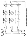
- Figure 5 shows a prior art circuit for determining the value of electrode arc voltage
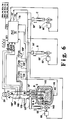
- Figure 6 is a block diagram and flow chart of a further embodiment of the present invention.
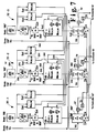
- Figure 7 shows a diagram and flow chart for a programmable controller for use in the present invention.
- Figure 1 is a schematic block diagram and flow chart illustrating a particular embodiment of the present invention.
- a three-phase electric furnace is shown at 10 with a scrap charge 20 contained and being melted therein which surrounds electrodes A, B, C which are respectively connected to separate phase windings of the secondary of a three-phase transformer 30.
- the neutral point of the three phase system is common with the furnace shell as indicated at 40 and the phase rotation of the three phase system for purposes of this description is A, B, C, i.e. the phase to neutral voltage at electrode A peaks before the voltage at electrode B and the voltage at electrode B peaks before the voltage at electrode C.
- Each electrode A, B, C is respectively provided with an identical conventional positioning device and a regulating system of which only the arrangement for one electrode is presented in full detail since the other arrangements are the same.
- the electrode positioning devices e.g.
- electrohydraulic systems 50, 50′, 50 ⁇ respond to the voltage signal output 55 of a conventional controller 60 which can suitably be of the proportional integral action, or other type.
- the voltage signal at 55 is developed in response to an error signal voltage at 70 which results from a comparison, e.g. the sum, of the voltages applied to summing network 80.
- Summing network 80 receives a signal at 90 which is proportional to the current in electrode A and is obtained from rectifier unit 100 in response to the continuous alternating current signal provided by current transformer 110 which is proportional to the current instantaneously flowing in electrode A.
- a scaling factor Fi is applied at 120 to provide a convenient voltage level for comparison at 70, e.g. 30 volts for an electrode current of 60 kA.
- phase-to-neutral voltage powering electrode A is measured at voltage transformer 125 and the alternating voltage signal thus obtained is rectified at voltage rectification unit 130 and a signal proportional to the voltage of electrode A is present at 140 and for routine operation of furnace 20 this signal is scaled by a scaling factor Fv1 at scaling unit 150 to provide to provide a convenient voltage level for comparison at 70 with the signal proportional to the current I A of electrode A, e.g. 30 volts for a phase-to-neutral voltage of 360 V.
- the scaling of the signal proportional to the phase-to-neutral voltage, V A , and the scaling of the electrode current, I A are conventionally adjustably settable and are selected so that the set values will establish a desired, predetermined height 143 of the tip of electrode A above scrap charge 30 as shown also in Figure 2.
- This pre-determined distance 143 establishes the length of arc 145, shown with more particularity in Figures 2-4, is routinely selected by the furnace operator on the basis of the type of charge material and well known furnace parameters, and the output 55 of controller 60, causes positioning device 50 to maintain the pre-determined distance 143 and the desired arc length 145 for electrode A in response to the error signal voltage at 70, raising the electrode A when the I A current signal applied to scaling unit 120 increases and lowering the electrode A when such signal decreases.
- This continuous regulating operation proceeds throughout routine meltdown of the charge for each of the electrodes A,B,C to provide optimum delivery of real power, MW, to the charge until a disruptive condition occurs such as, by way of example, a fall of scrap against an electrode which short circuits the electrode tip as illustrated at 150 in Figure 1 and Figure 3 for electrode B.
- a disruptive condition such as, by way of example, a fall of scrap against an electrode which short circuits the electrode tip as illustrated at 150 in Figure 1 and Figure 3 for electrode B.
- the current in the electrode B, I B greatly increases, increasing the voltage signal applied at 120′ and developing an error signal at 70′ which causes the positioning system 50′ for electrode B to rapidly raise electrode B to re-establish a distance, 143′, equal to the pre-determined distance 140 between the tip of electrode B and the scrap charge 20, at which time the routine regulation operation proceeds once again for electrode B as above-described.
- the arc voltages, V a A, V a B, V a C of the respective electrodes A, B, C are continuously determined and when one of these is determined to have a zero value, e.g. electrode B on account of a short circuiting scrap fall, the set point for the "phase ahead" electrode, in this exemplary case electrode A, is increased.
- a "Rogowski" coil 160 (such as described in BBC-Brown Bovari publication No. CH-1H 122 650F dated Lebada and Machler) is provided surrounding the secondary cable 70 for electrode A and identical coils 160′, 160" are provided for electrodes B and C.
- the arc voltage of an electrode is conveniently derived by subtracting inductive and resistive voltage drops from the secondary-to-ground phase voltages.
- the resistance values for r A , r B , r C and the mutual inductance "M" values vary for each furnace and are obtainable by measurement using conventional short circuit and open circuit tests on the particular furnace. Typical values for arc furnaces of 60 ton capacity and over are indicated in the table below.
- the determined values for the respective arc voltages V a B, V a C, V a A are obtained from summing network 75 and are applied respectively to the summing networks 80, 80′, 80′′ of the "phase ahead" electrodes; for example, when the arc voltage at electrode B, V a B, is determined at 75 to be zero, a relay device 140 responds to this condition and removes scaling factor FV1 from the summing network (FV3 hereinafter described is also out of the summing network for his condition) and scaling factor FV2 replaces FV1 in the summing network 80.
- FV3 hereinafter described is also out of the summing network for his condition
- scaling factor FV2 is larger than the scaling factor FV2 and as a result a higher voltage instantaneously appears at 70 and causes electrode A to move rapidly upward to increase the distance between the tip of electrode A and the scrap charge below and lengthen the arc at the tip of electrode A.
- scaling factor FV1 is selected at a value of about 0.5 to 0.85 which means that the initial set voltage appearing at 70 is 0.5 to 0.85 x the phase-to-neutral voltage powering the electrode A; the particular value in this range is selected routinely by the furnace operator based on the type of scrap and furnace parameters.
- a higher scaling factor in the range of 0.85 to 0.94 times the phase-to-neutral voltage powering electrode A is applied at 70 and this higher scaling factor remains operable until the arc voltage V a B of electrode B, the short circuited electrode, is determined to have increased from zero and returned to its-pre-scrap fall value, under which circumstances the relay device 140 re-instates FV1 as the operable scale factor for the phase-to-neutral voltage, V AU at summing network 80.
- a further type of disruptive occurrence can occur during scrap meltdown which is the falling away of scrap beneath an electrode to the extent that the arc of the electrode is extinguished and the electrode current becomes zero.
- the arc thereof is extinguished and the current in electrode B is determined to be zero, e.g. by the absence of a signal from Rogowski coil 160′.
- Electrode B is rapidly lowered under such circumstances to re-establish the pre-determined distance between its electrode tip and the scrap charge and relay device 140 simultaneously replaces scaling factor FV1 with scaling factor FV3 at both of the other electrodes, electrode A and electrode C, to provide an error voltage at 70 which will cause positioning means 50, 50′′ to rapidly lower both electrodes A and C to and thus shorten the arcs of electrodes A and C until the desired pre-determined distance between the tip of electrode B and the scrap charge is re-established.
- the scaling factor FV1 is selected at a value of 0.5 to 0.85 as hereinabove described
- FV3 is selected at a lower value of 0.28 to 0.49 X the phase-to-neutral voltage powering electrodes A and C and this lower scaling factor remains operable until the arc voltage of electrode B is reestablished.
- FIG. 6 A particular further embodiment of the present invention is illustrated in Figure 6 where summing network 75 of Figure 1 has been replaced by conventional programmable logical controllers at 75′, e.g. suitably commercially available units such as ALLEN BRADLEY PLC 5/15 which calculate the values of the arc voltages V a A, V a B, V a C in accordance with the relationships hereinabove described.
- the programmed logical controllers (PLC) 75′ receive the output of Rogowski coils 160, 160′, 160 ⁇ and values for the respective phase voltages VA, VB, VC, and provide output error signal voltages to controllers 60, 60′ and 60 ⁇ for the appropriate positioning of electodes A,B,C.
- PLC 75′-2 for the electrode B, short circuited by a scrapfall in the above described example, receives the output of Rogowski coil 160′ at 250 and phase voltage V B at 260 and resistance and inductance values are set at 262, 264, 266 for all electrode phases.
- the input from the Rogowski coil 160′ is integrated at 270 and the phase current I B is multiplied by the set value of r B at 280 which is subtracted from the phase voltage V B at 290 together with the applicable mutual reactance values as indicated in accordance with the cirucit of Figure 5, which are received at 292, 294.
- V a B The value determined for the arc voltage for phase B, V a B, is obtained from 290 at 295 and applied to network 800 where either scaling factor FV1 or FV2 or FV3 is applied to the phase voltage V A for the phase ahead i.e. phase A.
- V a B is not equal to zero, i.e. routine regulation conditions prevail, scaling factor FV1 is only applied to V A , the phase ahead voltage and the scaled voltage is compared at 310 to the pre-set signal, I A xFi; when V a B is equal to zero, i.e. a short circuit at electrode B due to a scrapfall, FV2 is only applied to V A , the phase ahead voltage i.e.
- phase A when either the phase current I B or the phase current I c of the other phases is zero, due to arc extinguishment by collapse of scrap at either electrode A or C, FV3 is only applied to the phase voltage V A .
- the respective scaled voltage obtained at 300 is summed at 310 with the scaled phase current I A of the phase ahead and the resultant error signal at 70 is applied to controller 60 of Figure 6 to move the positioning means 50′ for electrode B to achieve the results and benefits hereinbefore described.
- the PLC 75′-1 and 75′-3 for phases A and C respectively are similar to PLC 75′-1 for phase B described above and function in the same manner to determine arc voltages V a A and V a C for electrodes A and C and provide error signals in the same manner for controllers 60 ⁇ and 60′.
Abstract
Description
- The present invention relates to a system for controlling the length of the arc of one or more of the three electrodes of a three phase electric arc furnace. More particularly, the present invention relates to a system wherein the pre-set voltage of a controller which regulates the height of an electrode above the furnace scrap charge is adjusted upon the occurrence of a disruptive event at another electrode, e.g. a short circuit or loss of arc due to scrap fall, so that electrode arc lengths are changed and increased real power, MW, is delivered to the furnace during such events leading to increased furnace efficiency.
- Electric arc furnaces are widely used for the production of hot metal from iron and steel scrap and the overall objective in arc furnace melting is to produce hot metal of the desired quality at the lowest cost. By conducting meltdown, i.e. the melting of scrap, at optimum power levels and minimizing the time duration of interruptions of optimum power level operation during meltdown a maximum cost saving can be achieved since most of the energy required in producing hot metal product is used during meltdown. In a three phase electric arc furnace, the secondary circuit of a three phase transformer is connected to the three electrodes of the furnace so that each electrode is powered by a different phase of the secondary circuit, the powering phase voltage being the voltage from phase to neutral, i.e. ground, to which the furnace shell is electrically connected. At the beginning of the melting operation, i.e. melt down, metal scrap is charged to the furnace and the three electrodes descend toward the scrap charge. One of the electrodes first approaches the charge and stops and a second electrode approaches the charge and an arc is created at both electrodes. In this circumstance, the furnace is operating single phase, and, inefficiently, until the third electrode descends to create its arc and three phase furnace operation commences and scrap meltdown begins. In a typical commercial operation, an automatic regulator device is provided for each electrode and a set point voltage proportional to the phase voltage is selected for each regulator device to maintain a desired predetermined distance between each electrode tip and the scrap below. This distance (and the set point) is selected by the furnace operator based upon the type of charge material, available power input and other furnace parameters and is commonly about 100 to 300 mm. This selected pre-determined distance is maintained by the respective regulator devices during meltdown of the electrodes through the scrap by comparing the selected set point voltage with measured voltage and/or current information for each of the electrodes. The regulator operation proceeds routinely during melt-down to continuously maintain the predetermined distance between the electrode tips and the scrap below unless there is a disruptive occurrence, e.g. a "scrap fall" whereby scrap collapses inwardly toward and against the side of an electrode to thereby short circuit the electrode. Under such circumstances, current will increase substantially in the short-circuited electrode and also in an adjacent electrode. With conventional regulating systems the regulators of the thus affected electrodes will operate to rapidly raise these electrodes to quickly reduce current in the electrodes and then re-establish the pre-selected distance between the electrode tip and the scrap below, based on the initially selected set point voltage. While the short circuit due to scrap-fall persists the real power, MW, applied to the scrap charge is substantially lessened and the result is that the average real power applied to the furnace charge during meltdown is reduced and the cost of furnace operation correspondingly increased.
- In the situation where a scrap fall below the electrodes increases the distance from an electrode tip to the scrap so that the arc is extinguished, the particular electrode is open circuit and three phase operation is interrupted and the furnace operation is single phase, using only two arcs and there is a substantial drop in power delivered to the charge and furnace operation is thus highly inefficient. With conventional regulating systems, the regulator of the extinguished electrode operates to quickly lower this electrode to re-establish the pre-selected distance between the electrode tip and the scrap below based on the initially selected set point voltage. While the extinguished arc condition due to scrap fall persists the real power, MW, applied to the scrap charge is substantially lessened and the result is that the average real power applied to the furnace charge during meltdown is reduced and the cost of furnace operation correspondingly increased. It is accordingly an object of this invention to provide a regulation system for minimizing the reduction which occurs due to "scrap fall" at an electrode during meltdown.
- The present invention is an improvement in a system for the individual control of the arc furnace electrode positions of each of a first, second and third electrode in a three phase electric arc furnace wherein the electrodes are respectively powered by individual phase-to-neutral voltages of a transformer secondary winding having a relative phase sequence of first electrode before second electrode before third electrode (i.e. the voltage at the first electrode peaks, in time, before the voltage at the second electrode and the voltage at the second electrode peaks before the voltage at the third electrode). Each electrode of the furnace has a separate positioning means and a desired predetermined position of the respective electrodes is based on an individual pre-set voltage value which is proportional to the phase-to-neutral voltage powering such electrode and this voltage is continuously compared to a variable voltage responsive to the instantaneous position of such electrode. During routine furnace operation the result of the comparison is an error signal which is applied to the electrode positioning means, so as to cause the electrode positioning means to move such electrode toward its desired pre-determined position.
- For the disruptive occurrence situation where a scrap fall during meltdown results in the short circuit of a furnace electrode, first means are provided for respectively continuously determining the magnitude of the arc voltage of each electrode and means responsive to the first means are provided to instantaneously increase the pre-set voltage of one of the three electrodes of to increase the arc length of this electrode the furnace when the arc voltage of another of said electrodes is determined to be zero, the one said electrode being the electrode next ahead in phase rotation of said another electode.
- For the situation where a scrap fall during melt down results in the extinction of the arc of an electrode due to increased distance from the electrode tip to the scrap below, second means are provided for respectively continuously determining the magnitude of the arc current of each electrode and means are provided responsive to the second means to instantaneously decrease the pre-set voltage of two of the furnace electrodes to shorten the respective arc lengths thereof when the arc current of the other furnace electrode is determined to be zero.
- Figure 1 is a schematic block diagram and flow chart illustrating an embodiment of the present invention.
- Figure 2 illustrates a typical-electrode position during scrap melt down;
- Figure 3 illustrates a condition of scrap fall against an electrode causing a short circuit of the electrode arc;
- Figure 4 illustrates a condition of scrap fall beneath an electrode causing extinction of the electrode arc;
- Figure 5 shows a prior art circuit for determining the value of electrode arc voltage;
- Figure 6 is a block diagram and flow chart of a further embodiment of the present invention; and
- Figure 7 shows a diagram and flow chart for a programmable controller for use in the present invention.
- The present invention will be more fully understood with reference to Figure 1 which is a schematic block diagram and flow chart illustrating a particular embodiment of the present invention.
- With reference to Figure 1 a three-phase electric furnace is shown at 10 with a
scrap charge 20 contained and being melted therein which surrounds electrodes A, B, C which are respectively connected to separate phase windings of the secondary of a three-phase transformer 30. The neutral point of the three phase system is common with the furnace shell as indicated at 40 and the phase rotation of the three phase system for purposes of this description is A, B, C, i.e. the phase to neutral voltage at electrode A peaks before the voltage at electrode B and the voltage at electrode B peaks before the voltage at electrode C. Each electrode A, B, C is respectively provided with an identical conventional positioning device and a regulating system of which only the arrangement for one electrode is presented in full detail since the other arrangements are the same. The electrode positioning devices, e.g.electrohydraulic systems voltage signal output 55 of aconventional controller 60 which can suitably be of the proportional integral action, or other type. The voltage signal at 55 is developed in response to an error signal voltage at 70 which results from a comparison, e.g. the sum, of the voltages applied to summingnetwork 80. Summingnetwork 80 receives a signal at 90 which is proportional to the current in electrode A and is obtained fromrectifier unit 100 in response to the continuous alternating current signal provided bycurrent transformer 110 which is proportional to the current instantaneously flowing in electrode A. A scaling factor Fi is applied at 120 to provide a convenient voltage level for comparison at 70, e.g. 30 volts for an electrode current of 60 kA. The phase-to-neutral voltage powering electrode A is measured atvoltage transformer 125 and the alternating voltage signal thus obtained is rectified atvoltage rectification unit 130 and a signal proportional to the voltage of electrode A is present at 140 and for routine operation offurnace 20 this signal is scaled by a scaling factor Fv1 atscaling unit 150 to provide to provide a convenient voltage level for comparison at 70 with the signal proportional to the current IA of electrode A, e.g. 30 volts for a phase-to-neutral voltage of 360 V. The scaling of the signal proportional to the phase-to-neutral voltage, VA, and the scaling of the electrode current, IA, are conventionally adjustably settable and are selected so that the set values will establish a desired,predetermined height 143 of the tip of electrode Aabove scrap charge 30 as shown also in Figure 2. Thispre-determined distance 143 establishes the length ofarc 145, shown with more particularity in Figures 2-4, is routinely selected by the furnace operator on the basis of the type of charge material and well known furnace parameters, and theoutput 55 ofcontroller 60, causespositioning device 50 to maintain thepre-determined distance 143 and the desiredarc length 145 for electrode A in response to the error signal voltage at 70, raising the electrode A when the IA current signal applied toscaling unit 120 increases and lowering the electrode A when such signal decreases. This continuous regulating operation proceeds throughout routine meltdown of the charge for each of the electrodes A,B,C to provide optimum delivery of real power, MW, to the charge until a disruptive condition occurs such as, by way of example, a fall of scrap against an electrode which short circuits the electrode tip as illustrated at 150 in Figure 1 and Figure 3 for electrode B. Upon the occurrence of this situation, the current in the electrode B, IB, greatly increases, increasing the voltage signal applied at 120′ and developing an error signal at 70′ which causes thepositioning system 50′ for electrode B to rapidly raise electrode B to re-establish a distance, 143′, equal to thepre-determined distance 140 between the tip of electrode B and thescrap charge 20, at which time the routine regulation operation proceeds once again for electrode B as above-described. At the time of the above-described scrap-fall at electrode B, while the electrode current in electrode B greatly increases, but is not a definitive determination of a short circuit condition, the arc voltage VaB of electrode B is at zero level since it was short-circuited by thescrap fall 150 and the determination of a zero value arc voltage is a definitive determination of a short circuit condition. The power delivered by electrode B to thescrap charge 20 under these circumstances is minimal and the currents in the adjacent electrodes are substantially changed since furnace operation under such circumstances involves only two arcs. Until routine electrode regulation operation of electrode B is restored, which can take ten seconds or more, the real power, MW, delivered from the electrodes to thefurnace scrap charge 20 is substantially diminished. It has been discovered that the time required to re-establish routine electrode regulation and electric furnace operation can be shortened, and real power efficiency thus increased, when, upon the occurrence of a scrap fall which short circuits an electrode of a three phase electric furnace, the pre-determined desired set voltage for control of the desired, predetermined height of the electrode, which is next ahead in phase rotation, is immediately increased so that the electrode of the "phase ahead" is raised and its arc lengthened and regulation of this electrode is controlled by the newly established set point voltage until the initially, scrap fall short-circuited, electrode is re-established at its original pre-determined height and its arc voltage re-established. Upon this occurrence, the set point value of the "phase ahead" electrode is returned to its previous, initial value and routine electrode regulation continues as before the occurrence of the disruptive event. With reference to Figures 1 and 3 upon the occurrence of the above-mentioned scrap fall 150 which short circuits the tip of electrode B, the previously establishedarc 145′ is short circuited as indicated and the magnitude of its voltage drop VaB becomes zero. - In accordance with the improved system of the present invention, the arc voltages, VaA, VaB, VaC of the respective electrodes A, B, C are continuously determined and when one of these is determined to have a zero value, e.g. electrode B on account of a short circuiting scrap fall, the set point for the "phase ahead" electrode, in this exemplary case electrode A, is increased. For example, with reference to Figure 1, for electrode A, a "Rogowski" coil 160 (such as described in BBC-Brown Bovari publication No. CH-1H 122 650F dated Lebada and Machler) is provided surrounding the
secondary cable 70 for electrode A andidentical coils 160′, 160" are provided for electrodes B and C. These coils respectively develop induced signals:
coils 
where: - IA, IB, IC
- phase current flowing through electrodes A, B, C respectively
- rA, rB, rc
- ohmic resistance of the phase circuit from transformer secondary up to the electrode tip for phases A, B, C respectively.
- VaA, VaB, VaC
- electrode arc voltages from tip of electrode to charge (ground-neutral) for electrodes A, B, C respectively
- MAB,AM
- mutual inductance between the current loop "phase A to phase B" and the current loop "phase A to ground."
- MBA,BM
- mutual inductance between the current loop "phase B to phase A" and the current loop "phase B to ground."
- MCA,CM
- mutual inductance between the current loop "phase C to phase A" and the current loop "phase C to ground."
- MAC,AM
- mutual inductance between the current loop "phase A to phase C" and the current loop "phase A to ground."
- MBC,BM
- mutual inductance between the current loop "phase B to phase C" and the current loop "phase B to ground."
- MCB,CM
- mutual inductance between the current loop "phase C to phase B" and the current loop "phase C to ground-neutral"
- As can be seen, the arc voltage of an electrode is conveniently derived by subtracting inductive and resistive voltage drops from the secondary-to-ground phase voltages. The resistance values for rA, rB, rC and the mutual inductance "M" values vary for each furnace and are obtainable by measurement using conventional short circuit and open circuit tests on the particular furnace. Typical values for arc furnaces of 60 ton capacity and over are indicated in the table below.

- With the values for the above-described parameters established and with reference to Figure 1 the determined values for the respective arc voltages VaB, VaC, VaA are obtained from summing
network 75 and are applied respectively to the summingnetworks relay device 140 responds to this condition and removes scaling factor FV₁ from the summing network (FV₃ hereinafter described is also out of the summing network for his condition) and scaling factor FV₂ replaces FV₁ in the summingnetwork 80. The scaling factor FV₂ is larger than the scaling factor FV₂ and as a result a higher voltage instantaneously appears at 70 and causes electrode A to move rapidly upward to increase the distance between the tip of electrode A and the scrap charge below and lengthen the arc at the tip of electrode A. In commercial furnace operation, scaling factor FV₁ is selected at a value of about 0.5 to 0.85 which means that the initial set voltage appearing at 70 is 0.5 to 0.85 x the phase-to-neutral voltage powering the electrode A; the particular value in this range is selected routinely by the furnace operator based on the type of scrap and furnace parameters. Upon the determination that the arc voltage at electrode B, VaB, is zero, and the selection of scaling factor FV₂, a higher scaling factor in the range of 0.85 to 0.94 times the phase-to-neutral voltage powering electrode A is applied at 70 and this higher scaling factor remains operable until the arc voltage VaB of electrode B, the short circuited electrode, is determined to have increased from zero and returned to its-pre-scrap fall value, under which circumstances therelay device 140 re-instates FV₁ as the operable scale factor for the phase-to-neutral voltage, VAU at summingnetwork 80. - A further type of disruptive occurrence can occur during scrap meltdown which is the falling away of scrap beneath an electrode to the extent that the arc of the electrode is extinguished and the electrode current becomes zero. With reference to Figures 4 and 1, upon the falling away of scrap from beneath electrode B, as indicated at 200, the arc thereof is extinguished and the current in electrode B is determined to be zero, e.g. by the absence of a signal from
Rogowski coil 160′. Electrode B is rapidly lowered under such circumstances to re-establish the pre-determined distance between its electrode tip and the scrap charge andrelay device 140 simultaneously replaces scaling factor FV₁ with scaling factor FV₃ at both of the other electrodes, electrode A and electrode C, to provide an error voltage at 70 which will cause positioning means 50, 50′′ to rapidly lower both electrodes A and C to and thus shorten the arcs of electrodes A and C until the desired pre-determined distance between the tip of electrode B and the scrap charge is re-established. Under the conditions that the scaling factor FV₁ is selected at a value of 0.5 to 0.85 as hereinabove described, FV₃ is selected at a lower value of 0.28 to 0.49 X the phase-to-neutral voltage powering electrodes A and C and this lower scaling factor remains operable until the arc voltage of electrode B is reestablished. - Studies have shown that the afore described procedure of raising the "phase ahead" electrode upon the occurrence of a scrap fall which short circuits an electrode and the lowering of two electrodes upon the extinguishment of an electrode arc in the other electrode will lead to a MW increase of between 2 and 3% during scrap meltdown.
- A particular further embodiment of the present invention is illustrated in Figure 6 where summing
network 75 of Figure 1 has been replaced by conventional programmable logical controllers at 75′, e.g. suitably commercially available units such as ALLEN BRADLEY PLC 5/15 which calculate the values of the arc voltages VaA, VaB, VaC in accordance with the relationships hereinabove described. The programmed logical controllers (PLC) 75′ receive the output of Rogowski coils 160, 160′, 160˝ and values for the respective phase voltages VA, VB, VC, and provide output error signal voltages tocontrollers PLC 75′-2, for the electrode B, short circuited by a scrapfall in the above described example, receives the output ofRogowski coil 160′ at 250 and phase voltage VB at 260 and resistance and inductance values are set at 262, 264, 266 for all electrode phases. The input from theRogowski coil 160′ is integrated at 270 and the phase current IB is multiplied by the set value of rB at 280 which is subtracted from the phase voltage VB at 290 together with the applicable mutual reactance values as indicated in accordance with the cirucit of Figure 5, which are received at 292, 294. The value determined for the arc voltage for phase B, VaB, is obtained from 290 at 295 and applied to network 800 where either scaling factor FV₁ or FV₂ or FV₃ is applied to the phase voltage VA for the phase ahead i.e. phase A. When VaB is not equal to zero, i.e. routine regulation conditions prevail, scaling factor FV₁ is only applied to VA, the phase ahead voltage and the scaled voltage is compared at 310 to the pre-set signal, IAxFi; when VaB is equal to zero, i.e. a short circuit at electrode B due to a scrapfall, FV₂ is only applied to VA, the phase ahead voltage i.e. phase A; when either the phase current IB or the phase current Ic of the other phases is zero, due to arc extinguishment by collapse of scrap at either electrode A or C, FV₃ is only applied to the phase voltage VA. For any of the foregoing situations, the respective scaled voltage obtained at 300 is summed at 310 with the scaled phase current IA of the phase ahead and the resultant error signal at 70 is applied tocontroller 60 of Figure 6 to move the positioning means 50′ for electrode B to achieve the results and benefits hereinbefore described. - The
PLC 75′-1 and 75′-3 for phases A and C respectively are similar toPLC 75′-1 for phase B described above and function in the same manner to determine arc voltages VaA and VaC for electrodes A and C and provide error signals in the same manner forcontrollers 60˝ and 60′.
where:
where
where:
where:
* K. BRETTHAUER and K. TIMM: Electrowärme Int., March 1970, 28, 115-120.
Claims (5)
- In a system for the individual control of the arc furnace electrode positions of each of a first, second and third electrode in a three phase electric arc furnace respectively powered by individual phase-to-neutral voltages of a transformer secondary winding having a relative phase sequence of first electrode before second electrode before third electrode and having separate positioning means for each of said electrodes, a desired predetermined position of each of the electrodes being based on an individual pre-set voltage value proportional to the phase-to-neutral voltage powering such electrode which is in the range of about 0.5 to 0.85 of the magnitude of the phase-to-neutral voltage powering such electrode, said pre-set voltage being continuously compared to a variable voltage responsive to the instantaneous position of such electrode to provide an error voltage signal to cause raising or lowering of the electrode positioning means depending on the value of the error voltage signal, so as to cause the electrode positioning means to move such electrode toward its desired predetermined position;
the invention comprising:(i) first means for respectively continuously determining the magnitude of the arc voltage of each electrode;(ii) means responsive to said first means to increase the pre-set voltage of one of said electrodes when the arc voltage of another of said electrodes is determined to be zero, said one of said electrodes being the electrode next ahead in phase rotation of said another of said electrodes and said pre-set voltage increase being to a value in the range of about .85 to .94 of the magnitude of the phase-to-neutral voltage powering such electrode. - The invention according to claim 1 wherein second means are provided for respectively continuously determining the magnitude of the arc current of each electrode and means are provided responsive to said second means to decrease the pre-set voltage of two of said electrodes when the arc current of the other of said electrodes is determined to be zero, said voltage decrease for each of said two electrodes being in the range of about .28 to .49 of the phase-to-neutral voltage respectively powering such electrodes.
- In a system for the individual control of the arc furnace electrode positions of each of a first, second and third electrode in a three phase electric arc furnace respectively powered by individual phase-to-neutral voltages of a transformer secondary winding having a relative phase sequence of first electrode before second electrode before third electrode and having separate positioning means for each of said electrodes, a desired predetermined position of each of the electrodes being based on an individual pre-set voltage value proportional to the phase-to-neutral voltage powering such electrode which is in the range of about 0.5 to 0.85 of the magnitude of the phase-to-neutral voltage powering such electrode, said pre-set voltage being continuously compared to a variable voltage responsive to the instantaneous position of such electrode to provide an error voltage signal to cause raising or lowering of the electrode positioning means depending on the value of the error voltage signal, so as to cause the electrode positioning means to move such electrode toward its desired predetermined position;
the invention comprising:(i) first means for respectively continuously determining the magnitude of the arc voltage of each electrode;(ii) means responsive to said first means to increase the pre-set voltage of one of said electrodes when the arc voltage of another of said electrodes is determined to be zero, said one of said electrodes being the electrode next ahead in phase rotation of said another of said electrodes and said pre-set voltage increase being up to a value of about .94 of the magnitude of the phase-to-neutral voltage powering such electrode. - The invention according to claim 3 wherein second means are provided for respectively continuously determining the magnitude of the arc current of each electrode and means are provided responsive to said second means to decrease the pre-set voltage of two of said electrodes when the arc current of the other of said electrodes is determined to be zero, said voltage decrease for each of said two electrodes being down to about .28 of the phase-to-neutral voltage respectively powering such electrodes.
- The use of the system of any of claims 1 to 4 for operating a furnace.
Applications Claiming Priority (2)
| Application Number | Priority Date | Filing Date | Title |
|---|---|---|---|
| US639547 | 1991-01-10 | ||
| US07/639,547 US5115447A (en) | 1991-01-10 | 1991-01-10 | Arc furnace electrode control |
Publications (3)
| Publication Number | Publication Date |
|---|---|
| EP0494720A2 true EP0494720A2 (en) | 1992-07-15 |
| EP0494720A3 EP0494720A3 (en) | 1993-01-20 |
| EP0494720B1 EP0494720B1 (en) | 1995-03-08 |
Family
ID=24564550
Family Applications (1)
| Application Number | Title | Priority Date | Filing Date |
|---|---|---|---|
| EP92200056A Expired - Lifetime EP0494720B1 (en) | 1991-01-10 | 1992-01-09 | Arc furnace electrode control |
Country Status (6)
| Country | Link |
|---|---|
| US (1) | US5115447A (en) |
| EP (1) | EP0494720B1 (en) |
| AT (1) | ATE119734T1 (en) |
| CA (1) | CA2059062C (en) |
| DE (1) | DE69201573T2 (en) |
| MX (1) | MX9200092A (en) |
Cited By (10)
| Publication number | Priority date | Publication date | Assignee | Title |
|---|---|---|---|---|
| WO1999047873A1 (en) * | 1998-03-18 | 1999-09-23 | Elkem Asa | Method for determination of the tip position of consumable electrodes used in electric smelting furnaces |
| WO2004008600A3 (en) * | 2002-07-12 | 2004-03-18 | Mc Graw Edison Co | Electrical network protection system |
| US6810069B2 (en) | 2002-07-12 | 2004-10-26 | Mcgraw-Edison Company | Electrical arc furnace protection system |
| US6940702B2 (en) | 2002-07-12 | 2005-09-06 | Mcgraw-Edison Company | Electrical protection system |
| US7180717B2 (en) | 2002-07-12 | 2007-02-20 | Cooper Technologies Company | Electrical network protection system |
| US7564233B2 (en) | 2006-11-06 | 2009-07-21 | Cooper Technologies Company | Shielded Rogowski coil assembly and methods |
| US7638999B2 (en) | 2006-04-07 | 2009-12-29 | Cooper Technologies Company | Protective relay device, system and methods for Rogowski coil sensors |
| US7738221B2 (en) | 2007-12-07 | 2010-06-15 | Cooper Technologies Company | Transformer inrush current detector |
| CN102630107A (en) * | 2012-04-06 | 2012-08-08 | 南京理工大学常熟研究院有限公司 | Electrode lift control method of ore smelting electric arc furnace |
| RU2784312C1 (en) * | 2022-03-18 | 2022-11-23 | федеральное государственное бюджетное образовательное учреждение высшего образования "Санкт-Петербургский горный университет" | Electrode position and flow detection system |
Families Citing this family (16)
| Publication number | Priority date | Publication date | Assignee | Title |
|---|---|---|---|---|
| US5528136A (en) * | 1994-10-06 | 1996-06-18 | Teradyne, Inc. | VLSI component tester with average current measuring capability |
| DE19711453C2 (en) * | 1997-03-19 | 1999-02-25 | Siemens Ag | Process for regulating or controlling a melting process in a three-phase arc furnace |
| DE19733130A1 (en) * | 1997-07-31 | 1999-02-04 | Badische Stahl Eng | Method and device for detecting the state of slag and the stability of the arc in arc furnaces |
| US6411643B1 (en) | 1999-09-30 | 2002-06-25 | Sms Demag, Inc | Automatic electrode regulator based on direct power factor regulation and method |
| US6603795B2 (en) * | 2001-02-08 | 2003-08-05 | Hatch Associates Ltd. | Power control system for AC electric arc furnace |
| US6573691B2 (en) | 2001-10-17 | 2003-06-03 | Hatch Associates Ltd. | Control system and method for voltage stabilization in electric power system |
| US20050154611A1 (en) * | 2004-01-13 | 2005-07-14 | Sgl Carbon, Ag | Product support method for industrial processes |
| US7295593B2 (en) | 2004-09-01 | 2007-11-13 | Hatch Ltd. | System and method of minimizing loss of electrical conduction during input of feed material to a furnace |
| US20080056327A1 (en) * | 2006-08-30 | 2008-03-06 | Hatch Ltd. | Method and system for predictive electrode lowering in a furnace |
| JP5912976B2 (en) * | 2012-08-01 | 2016-04-27 | Jfeマテリアル株式会社 | Electrode lifting control method and apparatus for arc furnace |
| DE102014206008A1 (en) * | 2014-03-31 | 2015-10-01 | Siemens Aktiengesellschaft | Apparatus and method for dynamically adjusting an electric arc furnace |
| ITUB20152674A1 (en) * | 2015-07-30 | 2017-01-30 | Danieli Automation Spa | APPARATUS AND METHOD OF ELECTRIC SUPPLY OF AN ARC ELECTRIC OVEN |
| CN105896574B (en) * | 2016-06-12 | 2018-08-24 | 张家港浦项不锈钢有限公司 | A kind of method of 140 tonnes of electric arc furnaces electric load tranquilization operation |
| CN108021783B (en) * | 2017-11-08 | 2021-06-01 | 东北大学 | Method for calculating operating resistance of double-electrode direct-current magnesium melting furnace |
| CN113324402A (en) * | 2021-05-28 | 2021-08-31 | 牡丹江师范学院 | Automatic control system of three-phase electric arc smelting electric furnace |
| EP4110015A1 (en) | 2021-06-22 | 2022-12-28 | Primetals Technologies Germany GmbH | Operating method for a an arc furnace |
Citations (2)
| Publication number | Priority date | Publication date | Assignee | Title |
|---|---|---|---|---|
| US3597518A (en) * | 1970-02-27 | 1971-08-03 | Robicon Corp | Electric arc furnace control |
| DE2238006A1 (en) * | 1972-07-28 | 1974-02-07 | Licentia Gmbh | CONTROL DEVICE FOR THE ELECTRODE CONTROL OF ARC FURNACE |
Family Cites Families (8)
| Publication number | Priority date | Publication date | Assignee | Title |
|---|---|---|---|---|
| US3376374A (en) * | 1964-10-30 | 1968-04-02 | Westinghouse Electric Corp | Polyphase arc furnace with control system to raise one electrode prior to all electrodes striking an arc |
| US4096344A (en) * | 1976-09-30 | 1978-06-20 | Westinghouse Electric Corp. | Electric arc furnace control system |
| GB2001461B (en) * | 1977-07-21 | 1982-01-13 | Leybold Heraeus Gmbh & Co Kg | Arrangement for controlling the depth of immersion of self-consuming electrodes in electro-slag remelting furnaces |
| DE2948787C2 (en) * | 1979-12-04 | 1984-05-03 | Siemens AG, 1000 Berlin und 8000 München | Arrangement for the electrode control of an electric arc furnace |
| DE3023052A1 (en) * | 1980-06-20 | 1982-01-14 | Benteler-Werke Ag Werk Neuhaus, 4790 Paderborn | METHOD FOR RELEASING THE ELECTRODES OF AN ELECTRIC ARC FURNACE |
| DE3512177C2 (en) * | 1985-04-03 | 1997-01-16 | Mannesmann Ag | Method for symmetrizing electrical quantities in three-phase arc furnaces and device for carrying out the method |
| DE3512189C2 (en) * | 1985-04-03 | 1996-09-05 | Mannesmann Ag | Method and device for controlling arc furnaces |
| SU1453630A1 (en) * | 1987-01-07 | 1989-01-23 | Специальное проектно-конструкторское и технологическое бюро электротермического оборудования Производственного объединения "Сибэлектротерм" | Apparatus for automatic control of electric arc furnace operating mode |
-
1991
- 1991-01-10 US US07/639,547 patent/US5115447A/en not_active Expired - Lifetime
-
1992
- 1992-01-09 MX MX9200092A patent/MX9200092A/en unknown
- 1992-01-09 EP EP92200056A patent/EP0494720B1/en not_active Expired - Lifetime
- 1992-01-09 AT AT92200056T patent/ATE119734T1/en not_active IP Right Cessation
- 1992-01-09 CA CA 2059062 patent/CA2059062C/en not_active Expired - Lifetime
- 1992-01-09 DE DE1992601573 patent/DE69201573T2/en not_active Expired - Fee Related
Patent Citations (2)
| Publication number | Priority date | Publication date | Assignee | Title |
|---|---|---|---|---|
| US3597518A (en) * | 1970-02-27 | 1971-08-03 | Robicon Corp | Electric arc furnace control |
| DE2238006A1 (en) * | 1972-07-28 | 1974-02-07 | Licentia Gmbh | CONTROL DEVICE FOR THE ELECTRODE CONTROL OF ARC FURNACE |
Non-Patent Citations (4)
| Title |
|---|
| ELEKTROWARME INTERNATIONAL vol. 47, no. B1, February 1989, ESSEN DE pages B12 - B22 B. SCHWARZ & K. TIMM 'Control of electrical quantities in three-phase AC arc furnaces.' * |
| IRONMAKING AND STEELMAKING vol. 9, no. 4, 1982, pages 178 - 187 B. BOWMAN 'Solution of arc-furnace electrical circuit in terms of arc voltage' * |
| STAHL UND EISEN vol. 109, no. 19, September 1989, DUSSELDORF DE pages 917 - 920 S. KÖHLE ET AL. 'Messystem mit graphischer Darstellung für die elektrischen Grössen von Drehstrom-Lichtbogenöfen.' * |
| TECHNISCHE MITTEILUNGEN AEG TELEFUNKEN vol. 63, no. 6, 1973, BERLIN DE pages 232 - 236 A. BUXBAUM ET AL. 'Elektronische Regeleinrichtung für die Elektrodenregelung von Lichtbogenöfen.' * |
Cited By (14)
| Publication number | Priority date | Publication date | Assignee | Title |
|---|---|---|---|---|
| WO1999047873A1 (en) * | 1998-03-18 | 1999-09-23 | Elkem Asa | Method for determination of the tip position of consumable electrodes used in electric smelting furnaces |
| WO2004008600A3 (en) * | 2002-07-12 | 2004-03-18 | Mc Graw Edison Co | Electrical network protection system |
| US6810069B2 (en) | 2002-07-12 | 2004-10-26 | Mcgraw-Edison Company | Electrical arc furnace protection system |
| US6940702B2 (en) | 2002-07-12 | 2005-09-06 | Mcgraw-Edison Company | Electrical protection system |
| US7180717B2 (en) | 2002-07-12 | 2007-02-20 | Cooper Technologies Company | Electrical network protection system |
| AU2003247885B2 (en) * | 2002-07-12 | 2007-08-16 | Mcgraw-Edison Company | Electrical network protection system |
| CN1682419B (en) * | 2002-07-12 | 2012-12-05 | 库帕技术公司 | Electrical network protection system |
| US7902813B2 (en) | 2006-04-07 | 2011-03-08 | Cooper Technologies Company | Protective digital relay device |
| US7638999B2 (en) | 2006-04-07 | 2009-12-29 | Cooper Technologies Company | Protective relay device, system and methods for Rogowski coil sensors |
| US7564233B2 (en) | 2006-11-06 | 2009-07-21 | Cooper Technologies Company | Shielded Rogowski coil assembly and methods |
| US7902812B2 (en) | 2006-11-06 | 2011-03-08 | Cooper Technologies Company | Rogowski coil assembly and methods |
| US7738221B2 (en) | 2007-12-07 | 2010-06-15 | Cooper Technologies Company | Transformer inrush current detector |
| CN102630107A (en) * | 2012-04-06 | 2012-08-08 | 南京理工大学常熟研究院有限公司 | Electrode lift control method of ore smelting electric arc furnace |
| RU2784312C1 (en) * | 2022-03-18 | 2022-11-23 | федеральное государственное бюджетное образовательное учреждение высшего образования "Санкт-Петербургский горный университет" | Electrode position and flow detection system |
Also Published As
| Publication number | Publication date |
|---|---|
| ATE119734T1 (en) | 1995-03-15 |
| DE69201573D1 (en) | 1995-04-13 |
| US5115447A (en) | 1992-05-19 |
| EP0494720A3 (en) | 1993-01-20 |
| CA2059062A1 (en) | 1992-07-11 |
| CA2059062C (en) | 2000-05-09 |
| EP0494720B1 (en) | 1995-03-08 |
| MX9200092A (en) | 1992-07-01 |
| DE69201573T2 (en) | 1996-01-18 |
Similar Documents
| Publication | Publication Date | Title |
|---|---|---|
| EP0494720B1 (en) | Arc furnace electrode control | |
| US6603795B2 (en) | Power control system for AC electric arc furnace | |
| EP1436876B1 (en) | Control system and method for voltage stabilization | |
| CN101099413B (en) | Control apparatus for alternating-current reduction furnaces | |
| US4324944A (en) | Arrangement for controlling the electrodes of an arc furnace | |
| US4677643A (en) | Device for feeding one or a plurality of electrodes in an electrothermal furnace | |
| AU2002231514A1 (en) | Power control system for AC electric arc furnace | |
| JPH08205406A (en) | Method fdr stabilizing alternating current against reactive load fluctuation and apparatus for compensating reactive power | |
| JPH07170664A (en) | Method of stabilizing power circuit network against fluctuations in reactive load and reactive power compensating device | |
| JPH07211452A (en) | Adjusting method for d.c. arc furnace | |
| US3435121A (en) | Arc power responsive control system for consumable electrode furnace | |
| US2717326A (en) | Electric arc furnace control systems | |
| US3209060A (en) | Electrical apparatus | |
| US3536817A (en) | Electric furnace regulation system | |
| JP2979816B2 (en) | Method for switching speed of arc furnace electrode lifting device | |
| US5124521A (en) | Method and apparatus for controlling welding current in resistance welding | |
| CA1234595A (en) | System for control of the electroslag remelting | |
| JP2903915B2 (en) | Electrode lift control device for arc heating furnace | |
| JP2526554B2 (en) | Dissolution control method for AC arc furnace | |
| JPH05344653A (en) | Automatic voltage controller for power plant | |
| JPS61198312A (en) | Operation controller of low frequency induction furnace | |
| SU1202085A1 (en) | System for controlling electric conditions of three-phase electric-arc furnace | |
| JPH09274987A (en) | Power control method in melting furnace | |
| WO1995026118A1 (en) | Control of three-phase furnaces | |
| US1981994A (en) | Means for operating electric high frequency furnaces |
Legal Events
| Date | Code | Title | Description |
|---|---|---|---|
| PUAI | Public reference made under article 153(3) epc to a published international application that has entered the european phase |
Free format text: ORIGINAL CODE: 0009012 |
|
| AK | Designated contracting states |
Kind code of ref document: A2 Designated state(s): AT BE CH DE DK ES FR GB GR IT LI LU MC NL PT SE |
|
| PUAL | Search report despatched |
Free format text: ORIGINAL CODE: 0009013 |
|
| AK | Designated contracting states |
Kind code of ref document: A3 Designated state(s): AT BE CH DE DK ES FR GB GR IT LI LU MC NL PT SE |
|
| 17P | Request for examination filed |
Effective date: 19930120 |
|
| 17Q | First examination report despatched |
Effective date: 19931220 |
|
| GRAA | (expected) grant |
Free format text: ORIGINAL CODE: 0009210 |
|
| ITF | It: translation for a ep patent filed |
Owner name: BARZANO' E ZANARDO MILANO S.P.A. |
|
| AK | Designated contracting states |
Kind code of ref document: B1 Designated state(s): AT BE CH DE DK ES FR GB GR IT LI LU MC NL PT SE |
|
| PG25 | Lapsed in a contracting state [announced via postgrant information from national office to epo] |
Ref country code: GR Free format text: LAPSE BECAUSE OF FAILURE TO SUBMIT A TRANSLATION OF THE DESCRIPTION OR TO PAY THE FEE WITHIN THE PRESCRIBED TIME-LIMIT Effective date: 19950308 Ref country code: DK Effective date: 19950308 Ref country code: MC Free format text: LAPSE BECAUSE OF NON-PAYMENT OF DUE FEES Effective date: 19950308 Ref country code: ES Free format text: THE PATENT HAS BEEN ANNULLED BY A DECISION OF A NATIONAL AUTHORITY Effective date: 19950308 Ref country code: NL Free format text: LAPSE BECAUSE OF FAILURE TO SUBMIT A TRANSLATION OF THE DESCRIPTION OR TO PAY THE FEE WITHIN THE PRESCRIBED TIME-LIMIT Effective date: 19950308 Ref country code: BE Effective date: 19950308 Ref country code: AT Effective date: 19950308 Ref country code: LI Effective date: 19950308 Ref country code: CH Effective date: 19950308 |
|
| REF | Corresponds to: |
Ref document number: 119734 Country of ref document: AT Date of ref document: 19950315 Kind code of ref document: T |
|
| REF | Corresponds to: |
Ref document number: 69201573 Country of ref document: DE Date of ref document: 19950413 |
|
| PG25 | Lapsed in a contracting state [announced via postgrant information from national office to epo] |
Ref country code: PT Effective date: 19950608 Ref country code: SE Effective date: 19950608 |
|
| REG | Reference to a national code |
Ref country code: CH Ref legal event code: PL |
|
| ET | Fr: translation filed | ||
| NLV1 | Nl: lapsed or annulled due to failure to fulfill the requirements of art. 29p and 29m of the patents act | ||
| PLBE | No opposition filed within time limit |
Free format text: ORIGINAL CODE: 0009261 |
|
| STAA | Information on the status of an ep patent application or granted ep patent |
Free format text: STATUS: NO OPPOSITION FILED WITHIN TIME LIMIT |
|
| PG25 | Lapsed in a contracting state [announced via postgrant information from national office to epo] |
Ref country code: LU Free format text: LAPSE BECAUSE OF NON-PAYMENT OF DUE FEES Effective date: 19960131 |
|
| 26N | No opposition filed | ||
| REG | Reference to a national code |
Ref country code: GB Ref legal event code: IF02 |
|
| PGFP | Annual fee paid to national office [announced via postgrant information from national office to epo] |
Ref country code: GB Payment date: 20080129 Year of fee payment: 17 Ref country code: IT Payment date: 20080130 Year of fee payment: 17 |
|
| PGFP | Annual fee paid to national office [announced via postgrant information from national office to epo] |
Ref country code: DE Payment date: 20080229 Year of fee payment: 17 Ref country code: FR Payment date: 20080117 Year of fee payment: 17 |
|
| GBPC | Gb: european patent ceased through non-payment of renewal fee |
Effective date: 20090109 |
|
| PG25 | Lapsed in a contracting state [announced via postgrant information from national office to epo] |
Ref country code: DE Free format text: LAPSE BECAUSE OF NON-PAYMENT OF DUE FEES Effective date: 20090801 |
|
| REG | Reference to a national code |
Ref country code: FR Ref legal event code: ST Effective date: 20091030 |
|
| PG25 | Lapsed in a contracting state [announced via postgrant information from national office to epo] |
Ref country code: GB Free format text: LAPSE BECAUSE OF NON-PAYMENT OF DUE FEES Effective date: 20090109 |
|
| PG25 | Lapsed in a contracting state [announced via postgrant information from national office to epo] |
Ref country code: FR Free format text: LAPSE BECAUSE OF NON-PAYMENT OF DUE FEES Effective date: 20090202 |
|
| PG25 | Lapsed in a contracting state [announced via postgrant information from national office to epo] |
Ref country code: IT Free format text: LAPSE BECAUSE OF NON-PAYMENT OF DUE FEES Effective date: 20090109 |