EP0495340A1 - Modular construction kit for the tibial part of a knee joint prosthesis - Google Patents
Modular construction kit for the tibial part of a knee joint prosthesis Download PDFInfo
- Publication number
- EP0495340A1 EP0495340A1 EP91810972A EP91810972A EP0495340A1 EP 0495340 A1 EP0495340 A1 EP 0495340A1 EP 91810972 A EP91810972 A EP 91810972A EP 91810972 A EP91810972 A EP 91810972A EP 0495340 A1 EP0495340 A1 EP 0495340A1
- Authority
- EP
- European Patent Office
- Prior art keywords
- tibial plateau
- plane
- joint
- tibia
- snap connection
- Prior art date
- Legal status (The legal status is an assumption and is not a legal conclusion. Google has not performed a legal analysis and makes no representation as to the accuracy of the status listed.)
- Withdrawn
Links
Images

Classifications
-
- A—HUMAN NECESSITIES
- A61—MEDICAL OR VETERINARY SCIENCE; HYGIENE
- A61F—FILTERS IMPLANTABLE INTO BLOOD VESSELS; PROSTHESES; DEVICES PROVIDING PATENCY TO, OR PREVENTING COLLAPSING OF, TUBULAR STRUCTURES OF THE BODY, e.g. STENTS; ORTHOPAEDIC, NURSING OR CONTRACEPTIVE DEVICES; FOMENTATION; TREATMENT OR PROTECTION OF EYES OR EARS; BANDAGES, DRESSINGS OR ABSORBENT PADS; FIRST-AID KITS
- A61F2/00—Filters implantable into blood vessels; Prostheses, i.e. artificial substitutes or replacements for parts of the body; Appliances for connecting them with the body; Devices providing patency to, or preventing collapsing of, tubular structures of the body, e.g. stents
- A61F2/02—Prostheses implantable into the body
- A61F2/30—Joints
- A61F2/38—Joints for elbows or knees
- A61F2/389—Tibial components
-
- A—HUMAN NECESSITIES
- A61—MEDICAL OR VETERINARY SCIENCE; HYGIENE
- A61F—FILTERS IMPLANTABLE INTO BLOOD VESSELS; PROSTHESES; DEVICES PROVIDING PATENCY TO, OR PREVENTING COLLAPSING OF, TUBULAR STRUCTURES OF THE BODY, e.g. STENTS; ORTHOPAEDIC, NURSING OR CONTRACEPTIVE DEVICES; FOMENTATION; TREATMENT OR PROTECTION OF EYES OR EARS; BANDAGES, DRESSINGS OR ABSORBENT PADS; FIRST-AID KITS
- A61F2/00—Filters implantable into blood vessels; Prostheses, i.e. artificial substitutes or replacements for parts of the body; Appliances for connecting them with the body; Devices providing patency to, or preventing collapsing of, tubular structures of the body, e.g. stents
- A61F2/02—Prostheses implantable into the body
- A61F2/30—Joints
- A61F2002/30001—Additional features of subject-matter classified in A61F2/28, A61F2/30 and subgroups thereof
- A61F2002/30108—Shapes
- A61F2002/3011—Cross-sections or two-dimensional shapes
- A61F2002/30112—Rounded shapes, e.g. with rounded corners
- A61F2002/30133—Rounded shapes, e.g. with rounded corners kidney-shaped or bean-shaped
-
- A—HUMAN NECESSITIES
- A61—MEDICAL OR VETERINARY SCIENCE; HYGIENE
- A61F—FILTERS IMPLANTABLE INTO BLOOD VESSELS; PROSTHESES; DEVICES PROVIDING PATENCY TO, OR PREVENTING COLLAPSING OF, TUBULAR STRUCTURES OF THE BODY, e.g. STENTS; ORTHOPAEDIC, NURSING OR CONTRACEPTIVE DEVICES; FOMENTATION; TREATMENT OR PROTECTION OF EYES OR EARS; BANDAGES, DRESSINGS OR ABSORBENT PADS; FIRST-AID KITS
- A61F2/00—Filters implantable into blood vessels; Prostheses, i.e. artificial substitutes or replacements for parts of the body; Appliances for connecting them with the body; Devices providing patency to, or preventing collapsing of, tubular structures of the body, e.g. stents
- A61F2/02—Prostheses implantable into the body
- A61F2/30—Joints
- A61F2002/30001—Additional features of subject-matter classified in A61F2/28, A61F2/30 and subgroups thereof
- A61F2002/30316—The prosthesis having different structural features at different locations within the same prosthesis; Connections between prosthetic parts; Special structural features of bone or joint prostheses not otherwise provided for
- A61F2002/30329—Connections or couplings between prosthetic parts, e.g. between modular parts; Connecting elements
- A61F2002/30476—Connections or couplings between prosthetic parts, e.g. between modular parts; Connecting elements locked by an additional locking mechanism
- A61F2002/305—Snap connection
-
- A—HUMAN NECESSITIES
- A61—MEDICAL OR VETERINARY SCIENCE; HYGIENE
- A61F—FILTERS IMPLANTABLE INTO BLOOD VESSELS; PROSTHESES; DEVICES PROVIDING PATENCY TO, OR PREVENTING COLLAPSING OF, TUBULAR STRUCTURES OF THE BODY, e.g. STENTS; ORTHOPAEDIC, NURSING OR CONTRACEPTIVE DEVICES; FOMENTATION; TREATMENT OR PROTECTION OF EYES OR EARS; BANDAGES, DRESSINGS OR ABSORBENT PADS; FIRST-AID KITS
- A61F2/00—Filters implantable into blood vessels; Prostheses, i.e. artificial substitutes or replacements for parts of the body; Appliances for connecting them with the body; Devices providing patency to, or preventing collapsing of, tubular structures of the body, e.g. stents
- A61F2/02—Prostheses implantable into the body
- A61F2/30—Joints
- A61F2002/30001—Additional features of subject-matter classified in A61F2/28, A61F2/30 and subgroups thereof
- A61F2002/30316—The prosthesis having different structural features at different locations within the same prosthesis; Connections between prosthetic parts; Special structural features of bone or joint prostheses not otherwise provided for
- A61F2002/30535—Special structural features of bone or joint prostheses not otherwise provided for
- A61F2002/30604—Special structural features of bone or joint prostheses not otherwise provided for modular
-
- A—HUMAN NECESSITIES
- A61—MEDICAL OR VETERINARY SCIENCE; HYGIENE
- A61F—FILTERS IMPLANTABLE INTO BLOOD VESSELS; PROSTHESES; DEVICES PROVIDING PATENCY TO, OR PREVENTING COLLAPSING OF, TUBULAR STRUCTURES OF THE BODY, e.g. STENTS; ORTHOPAEDIC, NURSING OR CONTRACEPTIVE DEVICES; FOMENTATION; TREATMENT OR PROTECTION OF EYES OR EARS; BANDAGES, DRESSINGS OR ABSORBENT PADS; FIRST-AID KITS
- A61F2220/00—Fixations or connections for prostheses classified in groups A61F2/00 - A61F2/26 or A61F2/82 or A61F9/00 or A61F11/00 or subgroups thereof
- A61F2220/0025—Connections or couplings between prosthetic parts, e.g. between modular parts; Connecting elements
-
- A—HUMAN NECESSITIES
- A61—MEDICAL OR VETERINARY SCIENCE; HYGIENE
- A61F—FILTERS IMPLANTABLE INTO BLOOD VESSELS; PROSTHESES; DEVICES PROVIDING PATENCY TO, OR PREVENTING COLLAPSING OF, TUBULAR STRUCTURES OF THE BODY, e.g. STENTS; ORTHOPAEDIC, NURSING OR CONTRACEPTIVE DEVICES; FOMENTATION; TREATMENT OR PROTECTION OF EYES OR EARS; BANDAGES, DRESSINGS OR ABSORBENT PADS; FIRST-AID KITS
- A61F2230/00—Geometry of prostheses classified in groups A61F2/00 - A61F2/26 or A61F2/82 or A61F9/00 or A61F11/00 or subgroups thereof
- A61F2230/0002—Two-dimensional shapes, e.g. cross-sections
- A61F2230/0004—Rounded shapes, e.g. with rounded corners
- A61F2230/0015—Kidney-shaped, e.g. bean-shaped
Definitions
- the invention relates to a modular kit for the tibia part of a knee joint prosthesis consisting of a tibia plateau with pins from a stem protruding into the tibia and from a joint support made of polyethylene.
- tibia part of a knee prosthesis which consists of a tibial plateau with a peg and a joint support.
- the installation of these implants requires several individual preparatory work during resection of the tibia bone, which depend on the mechanical skill of the surgeon in order to support the implant over the entire intended area.
- the object of the invention is to provide the surgeon, who has performed a simple resection according to the bone condition found, with an implant whose fastening and insertion length can be adjusted intraoperatively.
- This object is achieved with the invention in that logs of different sizes can be inserted into the tibial plateau and in that joint supports of different heights in one plane of the tibial plateau guided on all sides by a swiveling movement can be brought into this plane by protrusions of the joint supports engaging in recesses of the tibial plateau in a tangentially arranged swivel axis and by engaging a snap connection between the joint support and tibial plateau opposite to the swivel axis.
- the advantage of the invention is that with a flat resection incision made in the correct angular position with respect to the tibia and with the fixing of the drilling pattern in the resection surface, all further functional dimensions are formed by assembling prefabricated components.
- the dependent claims 2 and 3 relate to advantageous developments of the invention.
- the figures show a modular kit for the tibia part of a knee joint prosthesis, which consists of a tibial plateau with a peg, a stem protruding into the tibia and a joint support made of polyethylene.
- Trunks of different sizes can be inserted into the tibial plateau, and joint supports of different heights are guided on all sides in one plane of the tibial plateau and can be brought into this plane by a pivoting movement. This is done by protrusions of the joint supports engaging in recesses of the tibial plateau in a tangentially arranged pivot axis and by snapping a snap connection between the joint support and tibial plateau opposite to the pivot axis.
- a tibial plateau 1 has a fixed drilling pattern for two pins 2 and a stem 3 lying in between, which is transferred to the flat resection surface 13 of a tibia bone 14.
- the holes for the pins 2 and the pin dimensions remain unchanged, since the pins mainly serve to prevent rotation in the resection plane, while the size of the interchangeable stem 3 and its associated hole can be gradually adapted to the fastening options in the tibia bone in order to anchor the tibia plateau.
- the different pins 3 are fastened with a screw 11 in the tibial plateau 1.
- the joint supports 4 are graded in different heights, while the connecting dimensions to a tibial plateau 1 are the same for all heights.
- the joint supports 4 lie in a plane 6, which is formed by the raised boundary edge 15 of the tibial plateau, and are guided in this plane by guide elements 10 with their protruding inner part 16, which is shaped to the contour of the upstanding boundary edge 15.
- the boundary edge 15 has on its inside two recesses 8, which lie on a common tangent to the inner part 16, while the inner part 16 has the projections 7, which by a Pivotal movement can be hooked into the recesses 8.
- the projections 7 and the cutouts 8 form a pivot axis 5, on which a one-sided securing against falling out of the plane 6 is created by pivoting in the joint support 4.
- a snap connection 9 is attached between the boundary edge 15 and the inner part 16, which snaps into place when the joint support 4 rests on the plane 6.
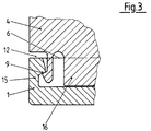
- a recess 12 is shown above the snap connection 9 between the boundary edge 15 and the joint support 4, into which a screwdriver-like tool can be used as a lever in order to release the hooking in the snap connection 9.
- the joint support 4 is guided independently of the snap connection perpendicular to the pivot axis 5 in the plane 6 through the boundary edge 15, so that no displacement forces in the plane 6 can act on the snap connection 9, ie the snap connection 9 secures perpendicular to the plane 6 and is not caused by changing Centering forces tired.
- the inner part 16 and the base of the tibial plateau 1 are less than 1/10 mm apart, so that additional load-bearing surfaces are created when the two parts are elastic.
Abstract
Description
Die Erfindung betrifft einen modularen Bausatz für den Tibiateil einer Kniegelenkprothese bestehend aus einem Tibiaplateau mit Zapfen aus einem in die Tibia hineinragenden Stamm und aus einer Gelenkauflage aus Polyäthylen.The invention relates to a modular kit for the tibia part of a knee joint prosthesis consisting of a tibia plateau with pins from a stem protruding into the tibia and from a joint support made of polyethylene.
In der CH-PS 667 383 ist der Tibiateil einer Kniegelenkprothese beschrieben, die aus einem Tibiaplateau mit Zapfen und aus einer Gelenkauflage besteht. Der Einbau dieser Implantate verlangt mehrere individuelle Vorbearbeitungen bei der Resektion des Tibiaknochens, die vom mechanischen Geschick des Operateurs abhängen, um das Implantat auf der ganzen vorgesehenen Fläche abzustützen.In CH-PS 667 383 the tibia part of a knee prosthesis is described, which consists of a tibial plateau with a peg and a joint support. The installation of these implants requires several individual preparatory work during resection of the tibia bone, which depend on the mechanical skill of the surgeon in order to support the implant over the entire intended area.
Aufgabe der Erfindung ist es, dem Operateur, der entsprechend dem vorgefundenen Knochenzustand eine einfache Resektion vorgenommen hat, ein Implantat zur Verfügung zu stellen, dessen Befestigungs- und Einbaulänge intraoperativ einstellbar sind. Diese Aufgabe wird mit der Erfindung dadurch gelöst, dass in das Tibiaplateau unterschiedlich grosse Stämme einsetzbar sind und dass unterschiedlich hohe Gelenkauflagen in einer Ebene des Tibiaplateaus allseitig geführt durch eine Schwenkbewegung in diese Ebene einbringbar sind, indem Vorsprünge der Gelenkauflagen in einer tangential angeordneten Schwenkachse in Aussparungen des Tibiaplateaus eingreifen und indem entgegengesetzt zur Schwenkachse eine Schnappverbindung zwischen Gelenkauflage und Tibiaplateau einrastet.The object of the invention is to provide the surgeon, who has performed a simple resection according to the bone condition found, with an implant whose fastening and insertion length can be adjusted intraoperatively. This object is achieved with the invention in that logs of different sizes can be inserted into the tibial plateau and in that joint supports of different heights in one plane of the tibial plateau guided on all sides by a swiveling movement can be brought into this plane by protrusions of the joint supports engaging in recesses of the tibial plateau in a tangentially arranged swivel axis and by engaging a snap connection between the joint support and tibial plateau opposite to the swivel axis.
Der Vorteil der Erfindung besteht darin, dass mit einem ebenen, in der richtigen Winkellage zur Tibia durchgeführten Resektionsschnitt und mit der Festlegung des Bohrbildes in der Resektionsfläche alle weiteren Funktionsmasse durch Zusammenfügen von vorgefertigten Bauteilen gebildet werden. Die abhängigen Ansprüche 2 und 3 beziehen sich auf vorteilhafte Weiterbildungen der Erfindung.The advantage of the invention is that with a flat resection incision made in the correct angular position with respect to the tibia and with the fixing of the drilling pattern in the resection surface, all further functional dimensions are formed by assembling prefabricated components. The
Im folgenden wird die Erfindung anhand eines Ausführungsbeispiels im Zusammenhang mit der Zeichnung näher erläutert. Es zeigen:
- Fig. 1
- schematisch einen abgesetzten Längsschnitt (I-I, Fig. 2) durch den Tibiateil für eine Kniegelenkprothese;
- Fig. 2
- schematisch die Draufsicht auf eine Gelenkauflage gemäss Fig. 1, unter der die Lage von Zapfen, Stamm und Schwenkachse angedeutet ist; und
- Fig. 3
- schematisch den vergrösserten Ausschnitt einer Schnappverbindung gemäss Fig. 1.
- Fig. 1
- schematically shows a stepped longitudinal section (II, Fig. 2) through the tibia part for a knee joint prosthesis;
- Fig. 2
- schematically the top view of a joint support according to Figure 1, under which the position of the pin, stem and pivot axis is indicated. and
- Fig. 3
- schematically the enlarged section of a snap connection according to FIG. 1.
In den Figuren ist ein modularer Bausatz für den Tibiateil einer Kniegelenkprothese gezeigt, der aus einem Tibiaplateau mit Zapfen, aus einem in die Tibia hineinragenden Stamm und aus einer Gelenkauflage aus Polyäthylen besteht.The figures show a modular kit for the tibia part of a knee joint prosthesis, which consists of a tibial plateau with a peg, a stem protruding into the tibia and a joint support made of polyethylene.
In das Tibiaplateau sind unterschiedlich grosse Stämme einsetzbar und unterschiedlich hohe Gelenkauflagen sind in einer Ebene des Tibiaplateaus allseitig geführt und durch eine Schwenkbewegung in diese Ebene einbringbar. Dies geschieht, indem Vorsprünge der Gelenkauflagen in einer tangential angeordneten Schwenkachse in Aussparungen des Tibiaplateaus eingreifen und indem entgegengesetzt zur Schwenkachse eine Schnappverbindung zwischen Gelenkauflage und Tibiaplateau einrastet.Trunks of different sizes can be inserted into the tibial plateau, and joint supports of different heights are guided on all sides in one plane of the tibial plateau and can be brought into this plane by a pivoting movement. This is done by protrusions of the joint supports engaging in recesses of the tibial plateau in a tangentially arranged pivot axis and by snapping a snap connection between the joint support and tibial plateau opposite to the pivot axis.
Ein Tibiaplateau 1 besitzt ein festes Bohrbild für zwei Zapfen 2 und einen dazwischen liegenden Stamm 3, welches auf die ebene Resektionsfläche 13 eines Tibiaknochens 14 übertragen wird. Die Bohrungen für die Zapfen 2 und die Zapfendimensionen bleiben unverändert, da die Zapfen hauptsächlich der Verdrehsicherung in der Resektionsebene dienen, während der auswechselbare Stamm 3 und seine zugehörige Bohrung in ihrer Grösse stufenweise den Befestigungsmöglichkeiten im Tibiaknochen anpassbar sind, um das Tibiaplateau zu verankern. Die unterschiedlichen Zapfen 3 sind mit einer Verschraubung 11 im Tibiaplateau 1 befestigt.A
Die Gelenkauflagen 4 liegen in unterschiedliche Höhen gestuft vor, während die Anschlussmasse zu einem Tibiaplateau 1 für alle Höhen gleich sind. Die Gelenkauflagen 4 liegen in einer Ebene 6, die durch den hochgezogenen Begrenzungsrand 15 des Tibiaplateaus gebildet wird, auf und sind in dieser Ebene durch Führungselemente 10 mit ihrem vorstehenden Innenteil 16 geführt, das der Kontur des hochstehenden Begrenzungsrandes 15 nachgeformt ist. Posterior weist der Begrenzungsrand 15 auf seiner Innenseite zwei Aussparungen 8 auf, die auf einer gemeinsamen Tangente an den Innenteil 16 liegen, während der Innenteil 16 der Vorsprünge 7 besitzt, die durch eine Schwenkbewegung in die Aussparungen 8 einhängbar sind. Die Vorsprünge 7 und die Aussparungen 8 bilden eine Schwenkachse 5, an der durch Einschwenken der Gelenkauflage 4 eine einseitige Sicherung gegen Herausfallen aus der Ebene 6 entsteht. Auf der Gegenseite zur Schwenkbachse 5 ist eine Schappverbindung 9 zwischen Begrenzungsrand 15 und Innenteil 16 angebracht, die mit dem Aufliegen der Gelenkauflage 4 auf der Ebene 6 einrastet. In Fig. 3 ist über der Schnappverbindung 9 zwischen Begrenzungsrand 15 und Gelenkauflage 4 eine Ausnehmung 12 gezeigt, in die ein schraubenzieherähnliches Werkzeug als Hebel einsetzbar ist, um die Verhakung in der Schnappverbindung 9 zu lösen. Die Gelenkauflage 4 ist unabhängig von der Schnappverbindung senkrecht zur Schwenkachse 5 in der Ebene 6 durch den Begrenzungsrand 15 geführt, damit keine Verschiebekräfte in der Ebene 6 auf die Schnappverbindung 9 wirken können, d.h. die Schnappverbindung 9 sichert senkrecht zur Ebene 6 und wird nicht durch wechselnde Zentrierkräfte ermüdet. Im montierten Zustand sind der Innenteil 16 und der Grund des Tibiaplateaus 1 weniger als 1/10 mm voneinander entfernt, damit im Rahmen der Elastizität der beiden Teile weitere tragende Flächen bei Belastung entstehen.The
- 11
- TibiaplateauTibial Plateau
- 22nd
- ZapfenCones
- 33rd
- Stammtribe
- 44th
- GelenkauflageJoint support
- 55
- SchwenkachseSwivel axis
- 66
- Ebenelevel
- 77
- Vorsprunghead Start
- 88th
- AussparungRecess
- 99
- SchnappverbindungSnap connection
- 1010th
- FührungselementeGuide elements
- 1111
- VerschraubungScrew connection
- 1212
- AusnehmungRecess
- 1313
- ResektionsflächeResection area
- 1414
- TibiaknochenTibia bone
- 1515
- BegrenzungsrandBorder
- 1616
- Innenteilinner part
Claims (3)
Applications Claiming Priority (2)
| Application Number | Priority Date | Filing Date | Title |
|---|---|---|---|
| CH14391 | 1991-01-18 | ||
| CH143/91 | 1991-01-18 |
Publications (1)
| Publication Number | Publication Date |
|---|---|
| EP0495340A1 true EP0495340A1 (en) | 1992-07-22 |
Family
ID=4180231
Family Applications (1)
| Application Number | Title | Priority Date | Filing Date |
|---|---|---|---|
| EP91810972A Withdrawn EP0495340A1 (en) | 1991-01-18 | 1991-12-13 | Modular construction kit for the tibial part of a knee joint prosthesis |
Country Status (1)
| Country | Link |
|---|---|
| EP (1) | EP0495340A1 (en) |
Cited By (53)
| Publication number | Priority date | Publication date | Assignee | Title |
|---|---|---|---|---|
| WO1994009725A1 (en) * | 1992-10-30 | 1994-05-11 | Encore Orthopedics, Inc. | Prosthesis system |
| FR2700261A1 (en) * | 1993-01-08 | 1994-07-13 | Erato | Knee prosthesis for inner or outer lateral fitting |
| DE4322619C1 (en) * | 1993-07-07 | 1994-09-22 | S & G Implants Gmbh | Tibial component of a knee-joint endoprosthesis |
| FR2716619A1 (en) * | 1994-02-25 | 1995-09-01 | Lepine Groupe | Tibial component for knee joint replacement prosthesis |
| FR2719213A1 (en) * | 1994-04-27 | 1995-11-03 | Fii | Knee prosthesis tibial implant |
| EP0738504A1 (en) * | 1995-04-20 | 1996-10-23 | SULZER Medizinaltechnik AG | Tibial tray for a knee joint prosthesis |
| FR2733411A1 (en) * | 1995-04-28 | 1996-10-31 | Howmedica France | Tibial prosthesis for knee joint |
| EP0749733A1 (en) * | 1995-06-21 | 1996-12-27 | Sulzer Orthopädie AG | Tibialplatform for a knee-joint prosthesis and knee-joint prosthesis with such a tibialplatform |
| FR2738739A1 (en) * | 1995-09-15 | 1997-03-21 | Rousseau Jacques Marie | Single-cotylar sliding knee joint replacement prosthesis |
| EP0776636A1 (en) * | 1995-11-30 | 1997-06-04 | Tornier Sa | Fixing device for a prosthesis, especially for a glenoid prosthesis of a shoulder blade |
| GB2312377A (en) * | 1996-04-24 | 1997-10-29 | Roozbeh Shirandami | Three part prosthetic knee joint with anterior posterior sliding action |
| FR2771281A1 (en) * | 1997-11-24 | 1999-05-28 | Implants & Instr Chirurg | Tibial implant, used as knee joint prosthesis |
| WO2001041680A1 (en) * | 1999-12-08 | 2001-06-14 | Ortho Development Corp. | Tibial prosthesis locking system |
| US6306172B1 (en) | 1999-01-28 | 2001-10-23 | Johnson & Johnson Professional, Inc. | Modular tibial insert for prosthesis system |
| EP1329205A1 (en) * | 2002-01-18 | 2003-07-23 | Finsbury (Development) Limited | Prosthesis |
| US6709461B2 (en) | 1999-02-03 | 2004-03-23 | Depuy Products, Inc. | Modular joint prosthesis system |
| DE10257774A1 (en) * | 2002-12-10 | 2004-07-29 | Hjs Gelenk System Gmbh | Artificial joint |
| EP2053992A2 (en) * | 2006-08-22 | 2009-05-06 | Exactech, Inc. | System and method for adjusting the thickness of a prosthesis |
| US7628818B2 (en) | 2007-09-28 | 2009-12-08 | Depuy Products, Inc. | Fixed-bearing knee prosthesis having interchangeable components |
| US7842093B2 (en) | 2006-07-18 | 2010-11-30 | Biomet Manufacturing Corp. | Method and apparatus for a knee implant |
| US7857858B2 (en) | 2002-04-25 | 2010-12-28 | Zimmer Technology, Inc. | Modular bone implant, tool, and method |
| US7998217B1 (en) | 2005-02-02 | 2011-08-16 | Biomet Manufacturing Corp. | Modular offset stem implants |
| US8029573B2 (en) | 2006-12-07 | 2011-10-04 | Ihip Surgical, Llc | Method and apparatus for total hip replacement |
| US8128703B2 (en) | 2007-09-28 | 2012-03-06 | Depuy Products, Inc. | Fixed-bearing knee prosthesis having interchangeable components |
| EP2574311A1 (en) * | 2011-09-28 | 2013-04-03 | DePuy Products, Inc. | Fixed-bearing knee prosthesis having a locking mechanism with a concave-to-convex mating interface |
| US8470047B2 (en) | 2007-09-25 | 2013-06-25 | Depuy (Ireland) | Fixed-bearing knee prosthesis |
| US8568486B2 (en) | 2010-07-24 | 2013-10-29 | Zimmer, Inc. | Asymmetric tibial components for a knee prosthesis |
| US8579985B2 (en) | 2006-12-07 | 2013-11-12 | Ihip Surgical, Llc | Method and apparatus for hip replacement |
| US8591594B2 (en) | 2010-09-10 | 2013-11-26 | Zimmer, Inc. | Motion facilitating tibial components for a knee prosthesis |
| US8628580B2 (en) | 2010-07-24 | 2014-01-14 | Zimmer, Inc. | Tibial prosthesis |
| US8632600B2 (en) | 2007-09-25 | 2014-01-21 | Depuy (Ireland) | Prosthesis with modular extensions |
| US8715359B2 (en) | 2009-10-30 | 2014-05-06 | Depuy (Ireland) | Prosthesis for cemented fixation and method for making the prosthesis |
| US8758444B2 (en) | 2011-11-21 | 2014-06-24 | Zimmer, Inc. | Tibial baseplate with asymmetric placement of fixation structures |
| US8784496B2 (en) | 2008-06-30 | 2014-07-22 | Depuy (Ireland) | Orthopaedic knee prosthesis having controlled condylar curvature |
| US8834575B2 (en) | 2008-06-30 | 2014-09-16 | Depuy (Ireland) | Posterior stabilized orthopaedic knee prosthesis having controlled condylar curvature |
| US8974540B2 (en) | 2006-12-07 | 2015-03-10 | Ihip Surgical, Llc | Method and apparatus for attachment in a modular hip replacement or fracture fixation device |
| US9011547B2 (en) | 2010-01-21 | 2015-04-21 | Depuy (Ireland) | Knee prosthesis system |
| US9119723B2 (en) | 2008-06-30 | 2015-09-01 | Depuy (Ireland) | Posterior stabilized orthopaedic prosthesis assembly |
| US9168145B2 (en) | 2008-06-30 | 2015-10-27 | Depuy (Ireland) | Posterior stabilized orthopaedic knee prosthesis having controlled condylar curvature |
| US9204967B2 (en) | 2007-09-28 | 2015-12-08 | Depuy (Ireland) | Fixed-bearing knee prosthesis having interchangeable components |
| US9204968B2 (en) | 2008-06-30 | 2015-12-08 | Depuy (Ireland) | Posterior stabilized orthopaedic prosthesis |
| US9220601B2 (en) | 2008-06-30 | 2015-12-29 | Depuy (Ireland) | Orthopaedic femoral component having controlled condylar curvature |
| US9381090B2 (en) | 2010-07-24 | 2016-07-05 | Zimmer, Inc. | Asymmetric tibial components for a knee prosthesis |
| US9492280B2 (en) | 2000-11-28 | 2016-11-15 | Medidea, Llc | Multiple-cam, posterior-stabilized knee prosthesis |
| US9539099B2 (en) | 2008-06-30 | 2017-01-10 | Depuy Ireland Unlimited Company | Orthopaedic knee prosthesis having controlled condylar curvature |
| US10188530B2 (en) | 2010-12-17 | 2019-01-29 | Zimmer, Inc. | Provisional tibial prosthesis system |
| US10278827B2 (en) | 2015-09-21 | 2019-05-07 | Zimmer, Inc. | Prosthesis system including tibial bearing component |
| US10675153B2 (en) | 2017-03-10 | 2020-06-09 | Zimmer, Inc. | Tibial prosthesis with tibial bearing component securing feature |
| US10835380B2 (en) | 2018-04-30 | 2020-11-17 | Zimmer, Inc. | Posterior stabilized prosthesis system |
| US10898337B2 (en) | 2011-11-18 | 2021-01-26 | Zimmer, Inc. | Tibial bearing component for a knee prosthesis with improved articular characteristics |
| US11324599B2 (en) | 2017-05-12 | 2022-05-10 | Zimmer, Inc. | Femoral prostheses with upsizing and downsizing capabilities |
| US11324598B2 (en) | 2013-08-30 | 2022-05-10 | Zimmer, Inc. | Method for optimizing implant designs |
| US11426282B2 (en) | 2017-11-16 | 2022-08-30 | Zimmer, Inc. | Implants for adding joint inclination to a knee arthroplasty |
Citations (4)
| Publication number | Priority date | Publication date | Assignee | Title |
|---|---|---|---|---|
| EP0246050A2 (en) * | 1986-05-12 | 1987-11-19 | Dow Corning Wright Corporation | Tibial knee point prosthesis with removable articulating surface insert |
| US4795468A (en) * | 1987-12-23 | 1989-01-03 | Zimmer, Inc. | Mechanism and method for locking a bearing insert to the base of a prosthetic implant |
| US4944757A (en) * | 1988-11-07 | 1990-07-31 | Martinez David M | Modulator knee prosthesis system |
| FR2653992A1 (en) * | 1989-11-09 | 1991-05-10 | Berakassa Richard | Total sliding knee prosthesis |
-
1991
- 1991-12-13 EP EP91810972A patent/EP0495340A1/en not_active Withdrawn
Patent Citations (4)
| Publication number | Priority date | Publication date | Assignee | Title |
|---|---|---|---|---|
| EP0246050A2 (en) * | 1986-05-12 | 1987-11-19 | Dow Corning Wright Corporation | Tibial knee point prosthesis with removable articulating surface insert |
| US4795468A (en) * | 1987-12-23 | 1989-01-03 | Zimmer, Inc. | Mechanism and method for locking a bearing insert to the base of a prosthetic implant |
| US4944757A (en) * | 1988-11-07 | 1990-07-31 | Martinez David M | Modulator knee prosthesis system |
| FR2653992A1 (en) * | 1989-11-09 | 1991-05-10 | Berakassa Richard | Total sliding knee prosthesis |
Cited By (107)
| Publication number | Priority date | Publication date | Assignee | Title |
|---|---|---|---|---|
| WO1994009725A1 (en) * | 1992-10-30 | 1994-05-11 | Encore Orthopedics, Inc. | Prosthesis system |
| FR2700261A1 (en) * | 1993-01-08 | 1994-07-13 | Erato | Knee prosthesis for inner or outer lateral fitting |
| DE4322619C1 (en) * | 1993-07-07 | 1994-09-22 | S & G Implants Gmbh | Tibial component of a knee-joint endoprosthesis |
| FR2716619A1 (en) * | 1994-02-25 | 1995-09-01 | Lepine Groupe | Tibial component for knee joint replacement prosthesis |
| FR2719213A1 (en) * | 1994-04-27 | 1995-11-03 | Fii | Knee prosthesis tibial implant |
| US5645604A (en) * | 1995-04-20 | 1997-07-08 | Sulzer Medizinaltechnik Ag | Tibia platform for a knee joint prosthesis |
| EP0738504A1 (en) * | 1995-04-20 | 1996-10-23 | SULZER Medizinaltechnik AG | Tibial tray for a knee joint prosthesis |
| FR2733411A1 (en) * | 1995-04-28 | 1996-10-31 | Howmedica France | Tibial prosthesis for knee joint |
| US5911758A (en) * | 1995-06-21 | 1999-06-15 | Sulzer Orthopaedie Ag | Tibia platform for a knee joint prosthesis and knee joint prosthesis with such a tibia platform |
| EP0749733A1 (en) * | 1995-06-21 | 1996-12-27 | Sulzer Orthopädie AG | Tibialplatform for a knee-joint prosthesis and knee-joint prosthesis with such a tibialplatform |
| FR2738739A1 (en) * | 1995-09-15 | 1997-03-21 | Rousseau Jacques Marie | Single-cotylar sliding knee joint replacement prosthesis |
| EP0776636A1 (en) * | 1995-11-30 | 1997-06-04 | Tornier Sa | Fixing device for a prosthesis, especially for a glenoid prosthesis of a shoulder blade |
| FR2741796A1 (en) * | 1995-11-30 | 1997-06-06 | Tornier Sa | DEVICE FOR FIXING A PROSTHESIS AND PARTICULARLY A GLENOIDAL PROSTHESIS OF OMOPLATE |
| US5702447A (en) * | 1995-11-30 | 1997-12-30 | Tornier S.A. | Device for the attachment of a glenoid prosthesis of the shoulder blade |
| GB2312377A (en) * | 1996-04-24 | 1997-10-29 | Roozbeh Shirandami | Three part prosthetic knee joint with anterior posterior sliding action |
| GB2312377B (en) * | 1996-04-24 | 2000-04-26 | Roozbeh Shirandami | Prosthetic knee joint with anterior posterior sliding action |
| FR2771281A1 (en) * | 1997-11-24 | 1999-05-28 | Implants & Instr Chirurg | Tibial implant, used as knee joint prosthesis |
| US6306172B1 (en) | 1999-01-28 | 2001-10-23 | Johnson & Johnson Professional, Inc. | Modular tibial insert for prosthesis system |
| US6709461B2 (en) | 1999-02-03 | 2004-03-23 | Depuy Products, Inc. | Modular joint prosthesis system |
| WO2001041680A1 (en) * | 1999-12-08 | 2001-06-14 | Ortho Development Corp. | Tibial prosthesis locking system |
| US6379388B1 (en) * | 1999-12-08 | 2002-04-30 | Ortho Development Corporation | Tibial prosthesis locking system and method of repairing knee joint |
| US10188521B2 (en) | 2000-11-28 | 2019-01-29 | Medidea, Llc | Multiple-cam, posterior-stabilized knee prosthesis |
| US9492280B2 (en) | 2000-11-28 | 2016-11-15 | Medidea, Llc | Multiple-cam, posterior-stabilized knee prosthesis |
| US6869448B2 (en) | 2002-01-18 | 2005-03-22 | Finsbury (Development) Limited | Prosthesis |
| EP1329205A1 (en) * | 2002-01-18 | 2003-07-23 | Finsbury (Development) Limited | Prosthesis |
| US8241367B2 (en) | 2002-04-25 | 2012-08-14 | Zimmer, Inc. | Modular bone implant, tool, and method |
| US7857858B2 (en) | 2002-04-25 | 2010-12-28 | Zimmer Technology, Inc. | Modular bone implant, tool, and method |
| DE10257774A1 (en) * | 2002-12-10 | 2004-07-29 | Hjs Gelenk System Gmbh | Artificial joint |
| US7998217B1 (en) | 2005-02-02 | 2011-08-16 | Biomet Manufacturing Corp. | Modular offset stem implants |
| US7842093B2 (en) | 2006-07-18 | 2010-11-30 | Biomet Manufacturing Corp. | Method and apparatus for a knee implant |
| EP2053992A2 (en) * | 2006-08-22 | 2009-05-06 | Exactech, Inc. | System and method for adjusting the thickness of a prosthesis |
| EP2053992A4 (en) * | 2006-08-22 | 2013-11-20 | Exactech Inc | System and method for adjusting the thickness of a prosthesis |
| US8974540B2 (en) | 2006-12-07 | 2015-03-10 | Ihip Surgical, Llc | Method and apparatus for attachment in a modular hip replacement or fracture fixation device |
| US8795381B2 (en) | 2006-12-07 | 2014-08-05 | Ihip Surgical, Llc | Methods and systems for hip replacement |
| US8579985B2 (en) | 2006-12-07 | 2013-11-12 | Ihip Surgical, Llc | Method and apparatus for hip replacement |
| US8211183B2 (en) | 2006-12-07 | 2012-07-03 | Ihip Surgical, Llc | Methods and systems for total hip replacement |
| US9237949B2 (en) | 2006-12-07 | 2016-01-19 | Ihip Surgical, Llc | Method and apparatus for hip replacement |
| US8029573B2 (en) | 2006-12-07 | 2011-10-04 | Ihip Surgical, Llc | Method and apparatus for total hip replacement |
| US8632600B2 (en) | 2007-09-25 | 2014-01-21 | Depuy (Ireland) | Prosthesis with modular extensions |
| US9398956B2 (en) | 2007-09-25 | 2016-07-26 | Depuy (Ireland) | Fixed-bearing knee prosthesis having interchangeable components |
| US8470047B2 (en) | 2007-09-25 | 2013-06-25 | Depuy (Ireland) | Fixed-bearing knee prosthesis |
| US9278003B2 (en) | 2007-09-25 | 2016-03-08 | Depuy (Ireland) | Prosthesis for cementless fixation |
| US8128703B2 (en) | 2007-09-28 | 2012-03-06 | Depuy Products, Inc. | Fixed-bearing knee prosthesis having interchangeable components |
| US9204967B2 (en) | 2007-09-28 | 2015-12-08 | Depuy (Ireland) | Fixed-bearing knee prosthesis having interchangeable components |
| US7628818B2 (en) | 2007-09-28 | 2009-12-08 | Depuy Products, Inc. | Fixed-bearing knee prosthesis having interchangeable components |
| US9168145B2 (en) | 2008-06-30 | 2015-10-27 | Depuy (Ireland) | Posterior stabilized orthopaedic knee prosthesis having controlled condylar curvature |
| US9204968B2 (en) | 2008-06-30 | 2015-12-08 | Depuy (Ireland) | Posterior stabilized orthopaedic prosthesis |
| US11730602B2 (en) | 2008-06-30 | 2023-08-22 | Depuy Ireland Unlimited Company | Orthopaedic knee prosthesis having controlled condylar curvature |
| US8834575B2 (en) | 2008-06-30 | 2014-09-16 | Depuy (Ireland) | Posterior stabilized orthopaedic knee prosthesis having controlled condylar curvature |
| US11369478B2 (en) | 2008-06-30 | 2022-06-28 | Depuy Ireland Unlimited Company | Orthopaedic knee prosthesis having controlled condylar curvature |
| US9539099B2 (en) | 2008-06-30 | 2017-01-10 | Depuy Ireland Unlimited Company | Orthopaedic knee prosthesis having controlled condylar curvature |
| US11337823B2 (en) | 2008-06-30 | 2022-05-24 | Depuy Ireland Unlimited Company | Orthopaedic femoral component having controlled condylar curvature |
| US9119723B2 (en) | 2008-06-30 | 2015-09-01 | Depuy (Ireland) | Posterior stabilized orthopaedic prosthesis assembly |
| US9326864B2 (en) | 2008-06-30 | 2016-05-03 | Depuy (Ireland) | Orthopaedic knee prosthesis having controlled condylar curvature |
| US10849760B2 (en) | 2008-06-30 | 2020-12-01 | Depuy Ireland Unlimited Company | Orthopaedic knee prosthesis having controlled condylar curvature |
| US10729551B2 (en) | 2008-06-30 | 2020-08-04 | Depuy Ireland Unlimited Company | Orthopaedic knee prosthesis having controlled condylar curvature |
| US9452053B2 (en) | 2008-06-30 | 2016-09-27 | Depuy (Ireland) | Orthopaedic knee prosthesis having controlled condylar curvature |
| US9220601B2 (en) | 2008-06-30 | 2015-12-29 | Depuy (Ireland) | Orthopaedic femoral component having controlled condylar curvature |
| US10543098B2 (en) | 2008-06-30 | 2020-01-28 | Depuy Ireland Unlimited Company | Orthopaedic femoral component having controlled condylar curvature |
| US10265180B2 (en) | 2008-06-30 | 2019-04-23 | Depuy Ireland Unlimited Company | Orthopaedic knee prosthesis having controlled condylar curvature |
| US10179051B2 (en) | 2008-06-30 | 2019-01-15 | Depuy Ireland Unlimited Company | Orthopaedic knee prosthesis having controlled condylar curvature |
| US8784496B2 (en) | 2008-06-30 | 2014-07-22 | Depuy (Ireland) | Orthopaedic knee prosthesis having controlled condylar curvature |
| US9937049B2 (en) | 2008-06-30 | 2018-04-10 | Depuy Ireland Unlimited Company | Orthopaedic knee prosthesis having controlled condylar curvature |
| US9931216B2 (en) | 2008-06-30 | 2018-04-03 | Depuy Ireland Unlimited Company | Orthopaedic femoral component having controlled condylar curvature |
| US8715359B2 (en) | 2009-10-30 | 2014-05-06 | Depuy (Ireland) | Prosthesis for cemented fixation and method for making the prosthesis |
| US9011547B2 (en) | 2010-01-21 | 2015-04-21 | Depuy (Ireland) | Knee prosthesis system |
| US9295557B2 (en) | 2010-07-24 | 2016-03-29 | Zimmer, Inc. | Asymmetric tibial components for a knee prosthesis |
| US10195041B2 (en) | 2010-07-24 | 2019-02-05 | Zimmer, Inc. | Asymmetric tibial components for a knee prosthesis |
| US8764840B2 (en) | 2010-07-24 | 2014-07-01 | Zimmer, Inc. | Tibial prosthesis |
| US9381090B2 (en) | 2010-07-24 | 2016-07-05 | Zimmer, Inc. | Asymmetric tibial components for a knee prosthesis |
| US11224519B2 (en) | 2010-07-24 | 2022-01-18 | Zimmer, Inc. | Asymmetric tibial components for a knee prosthesis |
| US9763794B2 (en) | 2010-07-24 | 2017-09-19 | Zimmer, Inc. | Tibial prosthesis |
| US9192480B2 (en) | 2010-07-24 | 2015-11-24 | Zimmer, Inc. | Asymmetric tibial components for a knee prosthesis |
| US9763796B2 (en) | 2010-07-24 | 2017-09-19 | Zimmer, Inc. | Asymmetric tibial components for a knee prosthesis |
| US8628580B2 (en) | 2010-07-24 | 2014-01-14 | Zimmer, Inc. | Tibial prosthesis |
| US9861490B2 (en) | 2010-07-24 | 2018-01-09 | Zimmer, Inc. | Asymmetric tibial components for a knee prosthesis |
| US9918844B2 (en) | 2010-07-24 | 2018-03-20 | Zimmer, Inc. | Tibial prosthesis with a fixed bearing component |
| US10543099B2 (en) | 2010-07-24 | 2020-01-28 | Zimmer, Inc. | Tibial prosthesis |
| US10470889B2 (en) | 2010-07-24 | 2019-11-12 | Zimmer, Inc. | Asymmetric tibial components for a knee prosthesis |
| US9283082B2 (en) | 2010-07-24 | 2016-03-15 | Zimmer, Inc. | Methods related to seating of bearing component on tibial tray |
| US8568486B2 (en) | 2010-07-24 | 2013-10-29 | Zimmer, Inc. | Asymmetric tibial components for a knee prosthesis |
| US9314343B2 (en) | 2010-09-10 | 2016-04-19 | Zimmer, Inc. | Motion facilitating tibial components for a knee prosthesis |
| US10413415B2 (en) | 2010-09-10 | 2019-09-17 | Zimmer, Inc. | Motion facilitating tibial components for a knee prosthesis |
| US11471288B2 (en) | 2010-09-10 | 2022-10-18 | Zimmer, Inc. | Motion facilitating tibial components for a knee prosthesis |
| US9763795B2 (en) | 2010-09-10 | 2017-09-19 | Zimmer, Inc. | Motion facilitating tibial components for a knee prosthesis |
| US8591594B2 (en) | 2010-09-10 | 2013-11-26 | Zimmer, Inc. | Motion facilitating tibial components for a knee prosthesis |
| US10188530B2 (en) | 2010-12-17 | 2019-01-29 | Zimmer, Inc. | Provisional tibial prosthesis system |
| AU2012227334B2 (en) * | 2011-09-28 | 2015-07-02 | Depuy Products, Inc. | Fixed-bearing knee prosthesis having a locking mechanism with a concave-to-convex mating interface |
| EP2574311A1 (en) * | 2011-09-28 | 2013-04-03 | DePuy Products, Inc. | Fixed-bearing knee prosthesis having a locking mechanism with a concave-to-convex mating interface |
| JP2013071010A (en) * | 2011-09-28 | 2013-04-22 | Depuy Products Inc | Fixed-bearing knee prosthesis having locking mechanism with concave-to-convex mating interface |
| CN110074901A (en) * | 2011-09-28 | 2019-08-02 | 德普伊产品公司 | Fixed bearing knee prostheses with the locking mechanism with concave-convex matched interface |
| CN103027771A (en) * | 2011-09-28 | 2013-04-10 | 德普伊产品公司 | Fixed-bearing knee prosthesis having a locking mechanism with a concave-to-convex mating interface |
| US9814584B2 (en) | 2011-09-28 | 2017-11-14 | Depuy Ireland Unlimited Company | Fixed-bearing knee prosthesis having a locking mechanism with a concave-to-convex mating interface |
| US10898337B2 (en) | 2011-11-18 | 2021-01-26 | Zimmer, Inc. | Tibial bearing component for a knee prosthesis with improved articular characteristics |
| US10265181B2 (en) | 2011-11-21 | 2019-04-23 | Zimmer, Inc. | Tibial baseplate with asymmetric placement of fixation structures |
| US8758444B2 (en) | 2011-11-21 | 2014-06-24 | Zimmer, Inc. | Tibial baseplate with asymmetric placement of fixation structures |
| US9707089B2 (en) | 2011-11-21 | 2017-07-18 | Zimmer, Inc. | Tibial baseplate with asymmetric placement of fixation structures |
| US9308096B2 (en) | 2011-11-21 | 2016-04-12 | Zimmer, Inc. | Tibial baseplate with asymmetric placement of fixation structures |
| US11324598B2 (en) | 2013-08-30 | 2022-05-10 | Zimmer, Inc. | Method for optimizing implant designs |
| US11160659B2 (en) | 2015-09-21 | 2021-11-02 | Zimmer, Inc. | Prosthesis system including tibial bearing component |
| US10278827B2 (en) | 2015-09-21 | 2019-05-07 | Zimmer, Inc. | Prosthesis system including tibial bearing component |
| US11547571B2 (en) | 2017-03-10 | 2023-01-10 | Zimmer, Inc. | Tibial prosthesis with tibial bearing component securing feature |
| US10675153B2 (en) | 2017-03-10 | 2020-06-09 | Zimmer, Inc. | Tibial prosthesis with tibial bearing component securing feature |
| US11324599B2 (en) | 2017-05-12 | 2022-05-10 | Zimmer, Inc. | Femoral prostheses with upsizing and downsizing capabilities |
| US11426282B2 (en) | 2017-11-16 | 2022-08-30 | Zimmer, Inc. | Implants for adding joint inclination to a knee arthroplasty |
| US10835380B2 (en) | 2018-04-30 | 2020-11-17 | Zimmer, Inc. | Posterior stabilized prosthesis system |
| US11911279B2 (en) | 2018-04-30 | 2024-02-27 | Zimmer, Inc. | Posterior stabilized prosthesis system |
Similar Documents
| Publication | Publication Date | Title |
|---|---|---|
| EP0495340A1 (en) | Modular construction kit for the tibial part of a knee joint prosthesis | |
| EP0241792B1 (en) | Setting and driving tool for a bone nail | |
| DE60127275T2 (en) | KNEE PROSTHESIS WITH MOVABLE BEARING | |
| EP0680292B1 (en) | System for constructing a knee-joint endoprosthesis | |
| DE69725209T2 (en) | Acetabular trial prosthesis | |
| EP0717609B1 (en) | Prosthesis for small joints | |
| EP0279830B1 (en) | Modular-construction endoprosthesis for replacing a part of the pelvis in the hip region | |
| DE69729220T2 (en) | SET OF HUMERUS HEAD PROSTHESES | |
| DE69822266T2 (en) | Modular elbow prosthesis | |
| EP0158014B1 (en) | Hip prosthesis | |
| DE69924574T2 (en) | Components and tools for intramedullary revision surgery of the tibia | |
| DE69825472T2 (en) | SURGICAL IMPLANT AND SURGICAL FASTENING SCREW | |
| DE2041929A1 (en) | Prosthetic shoulder joint | |
| EP0306744B1 (en) | Tibial component of a knee joint endoprosthesis | |
| EP0447734B1 (en) | Femoral head prosthesis for cementless affixation | |
| EP0672397A1 (en) | Tibial plate for an artificial knee joint | |
| DE112010005471T5 (en) | End plate of an intervertebral implant and implant | |
| EP0563502B1 (en) | Metal stem | |
| DE4432033A1 (en) | Artificial vertebrae for implant in spine | |
| EP1620043A1 (en) | Knee joint prosthesis | |
| CH659580A5 (en) | THE BIG TROCHANT REPLACING IMPLANT. | |
| EP0177755B1 (en) | Tibial-prosthetic part of a knee joint endoprosthesis | |
| EP0025814B1 (en) | One-piece femur part of a hip joint endoprosthesis | |
| EP0607749A1 (en) | Artificial wrist joint | |
| DE4339895C1 (en) | System for designing a knee-joint endoprosthesis |
Legal Events
| Date | Code | Title | Description |
|---|---|---|---|
| PUAI | Public reference made under article 153(3) epc to a published international application that has entered the european phase |
Free format text: ORIGINAL CODE: 0009012 |
|
| AK | Designated contracting states |
Kind code of ref document: A1 Designated state(s): AT CH DE FR GB IT LI |
|
| 17P | Request for examination filed |
Effective date: 19920929 |
|
| 17Q | First examination report despatched |
Effective date: 19940418 |
|
| STAA | Information on the status of an ep patent application or granted ep patent |
Free format text: STATUS: THE APPLICATION IS DEEMED TO BE WITHDRAWN |
|
| 18D | Application deemed to be withdrawn |
Effective date: 19950223 |