EP0495558B1 - Method and apparatus for magnetic recording and reproducing - Google Patents
Method and apparatus for magnetic recording and reproducing Download PDFInfo
- Publication number
- EP0495558B1 EP0495558B1 EP92200452A EP92200452A EP0495558B1 EP 0495558 B1 EP0495558 B1 EP 0495558B1 EP 92200452 A EP92200452 A EP 92200452A EP 92200452 A EP92200452 A EP 92200452A EP 0495558 B1 EP0495558 B1 EP 0495558B1
- Authority
- EP
- European Patent Office
- Prior art keywords
- track
- region
- words
- reproduced
- recorded
- Prior art date
- Legal status (The legal status is an assumption and is not a legal conclusion. Google has not performed a legal analysis and makes no representation as to the accuracy of the status listed.)
- Expired - Lifetime
Links
Images


Classifications
-
- G—PHYSICS
- G11—INFORMATION STORAGE
- G11B—INFORMATION STORAGE BASED ON RELATIVE MOVEMENT BETWEEN RECORD CARRIER AND TRANSDUCER
- G11B20/00—Signal processing not specific to the method of recording or reproducing; Circuits therefor
- G11B20/10—Digital recording or reproducing
- G11B20/18—Error detection or correction; Testing, e.g. of drop-outs
- G11B20/1876—Interpolating methods
-
- G—PHYSICS
- G11—INFORMATION STORAGE
- G11B—INFORMATION STORAGE BASED ON RELATIVE MOVEMENT BETWEEN RECORD CARRIER AND TRANSDUCER
- G11B20/00—Signal processing not specific to the method of recording or reproducing; Circuits therefor
- G11B20/10—Digital recording or reproducing
- G11B20/10527—Audio or video recording; Data buffering arrangements
-
- G—PHYSICS
- G11—INFORMATION STORAGE
- G11B—INFORMATION STORAGE BASED ON RELATIVE MOVEMENT BETWEEN RECORD CARRIER AND TRANSDUCER
- G11B20/00—Signal processing not specific to the method of recording or reproducing; Circuits therefor
- G11B20/10—Digital recording or reproducing
- G11B20/18—Error detection or correction; Testing, e.g. of drop-outs
- G11B20/1806—Pulse code modulation systems for audio signals
- G11B20/1809—Pulse code modulation systems for audio signals by interleaving
Definitions
- the present invention relates to magnetic recorders and/or reproducers.
- a rotary head-type PCM magnetic recorder/reproducer which converts audio signals into digital signals for recording the digital signals in a magnetic tape and reproducing the recorded digital signals.
- a rotary head-type PCM magnetic recorder/reproducer employs error correction codes for correcting errors caused in the data upon recording/reproducing of the magnetic tape.
- the error correction codes are adapted to correct the errors caused in the data following recording/reproducing of the magnetic tape thereby to reproduce high definition audio signals.
- compensation must be performed by means such as interpolation by taking the mean value of adjacent data.
- most of the errors caused on the magnetic tape are burst errors, and hence the erroneous data are dispersed by interleaving processing for improving the ability of the error correction codes.
- compensation processing is performed when the errors cannot be corrected, and mean value interpolation is employed as an effective compensation process with simple circuit structure.
- mean value interpolation is performed on condition that the adjacent data are correct.
- Figs. 1 and 2 show magnetization patterns recorded on a magnetic tape by a conventional rotary head-type PCM magnetic recorder/reproducer.
- a magnetic tape T travels in the direction indicated by an arrow D and is scanned by rotary heads in the direction indicated by an arrow S.
- the data recorded in the magnetic tape T are of two channels A and B, and distributed into even sample groups a and odd sample groups b .
- symbol a with symbol A + B indicates even sample groups of the channels A and B
- symbol Aa indicates an even sample group of the channel A.
- the volume of interleaving is generally determined in consideration of burst length of errors and correction ability of error correction codes, and an even sample group a and an odd sample group b may be in line over a scanning interval, as shown in Fig. 1, or to the contrary.
- Fig. 2 shows the even sample groups a and the odd sample groups b arrayed in equally divided scanning intervals.
- GB-A-2038514 (corresponding to FR-A-2443171), US-A-4224642 and GB-A-2073935 all show arrangements in which samples of signals are permutated into groups so as to record the groups successively in a predetermined pattern in successive tracks of a tape.
- US-A-4224642 is concerned with recording a single channel, and discloses the recording of odd and even sample groups in alternate scanning intervals along each track.
- GB-A-2073935 is also concerned with the recording of a single channel. In this case interleaved samples are split into four groups, and each group is recorded along substantially the entire length of a respective track.
- a first group of odd samples is recorded in a first track
- a first group of even samples is recorded in the next track
- a second group of odd samples is recorded in the third track
- a second group of even samples is recorded in the fourth track.
- Sequentially occurring samples are also separated in the direction of the lengths of the tracks by a "statistically significant dropout length", to enhance the reliability of conventional dropout error concealment techniques.
- GB-A-2038514 is concerned with recording two channels, each of which is split into three sample groups, and the three sample groups of both channels are all recorded on a single track. All these arrangements suffer from the disadvantages referred to above.
- a preferred embodiment of the present invention provides a magnetic recorder/reproducer which can reduce noise caused by a silted rotary head and by errors in the tape travelling direction over a certain width along the cross direction of a magnetic tape.
- the preferred embodiment converts analog signals of a plurality of channels into digital signals to distribute the digital signals of the plurality of channels into odd sample groups and even sample groups per each channel, and permutates the sample groups so that the odd sample groups and the even sample groups of the same channel are recorded in alternate scanning intervals and in regions occupying different positions along the direction of scanning, thereby to record the permutated odd sample groups and even sample groups of the respective channels in a magnetic recording medium by magnetic heads.
- the signals may be readily corrected even if reproduced signals from one head are interrupted by, e.g. instantaneous silting of the head caused by magnetic powder coming off from the magnetic tape or a burst error is caused in the tape travelling direction over a wide range along the cross direction of the tape, whereby the signal-to-noise ratio of reproduced sounds or images can be improved. Further, excellent reproduced sounds and images can be obtained by properly selecting samples from the respective groups.
- even sample groups of a first channel and odd samples group of a second channel are arrayed in the same scanning intervals while odd sample groups of the first channel and even sample groups of the second channel are arrayed in scanning intervals adjacent to the said same scanning intervals, such that the odd sample groups and the even sample groups of the first channel are recorded in regions at different positions along the direction of scanning.
- the even sample groups of the first channel and the even sample groups of the second channel may be arrayed in the same scanning intervals while the odd sample groups of the first channel and the odd sample groups of the second channel are arrayed in scanning intervals adjacent to the said same scanning intervals in such a manner that the odd sample groups and the even sample groups of the first channel are recorded in regions at different positions along the direction of scanning.
- the respective sample groups recorded in the magnetic tape in the aforementioned manner are preferably reproduced by magnetic heads to be permutated in order of sample numbers per each channel and outputted to be converted into analog signals.
- the permutated odd sample group and even sample group of each channel in each scanning interval are encoded to generate error correction codes, which are arrayed in the scanning interval including information employed for generating the error correction codes.
- the error correction codes are so generated and arrayed as to be completed with respect to the data included in one scanning interval, thereby to prevent increase in the clock rate required for encoding and decoding of the data.
- Fig. 3 is an illustration showing a magnetization pattern recorded on a magnetic tape in an embodiment of the present invention.
- interleaving processing is characterized in that even sample groups and odd sample groups of the same channel are arrayed in alternate scanning intervals and in different regions, so that the regions are at different positions along the direction of scanning by rotary heads.
- even sample groups or the odd sample groups of the same channel can necessarily be obtained even if signals in one of two rotary heads are interrupted by the aforementioned silting, and hence no continuous sample errors are caused.
- either the even sample groups or the odd sample groups of the same channel can be obtained to half the width of the magnetic tape in the cross direction as shown in Fig. 3, whereby no continuous sample errors are caused in the same channel.
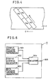
- Fig. 4 is an illustration showing another example of the magnetization pattern. Also in the example as shown in Fig. 4, even sample groups and odd sample groups of the same channel are arrayed in alternate scanning intervals and in different regions located at different positions along the direction of scanning, and hence no sample errors are caused by interruption of signals similarly to the example as shown in Fig. 3.
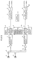
- Fig. 5 is a schematic block diagram showing an embodiment of the present invention and Fig. 6 is a schematic block diagram showing a memory address control circuit as shown in Fig. 5.
- a rotary head-type PCM magnetic recorder/reproducer consists of a recording system and a reproducing system.
- a two-channel input terminal 1 of the recording system receives analog audio signals.
- the analog audio signals inputted in the input terminal 1 are supplied to a low-pass filter 2 to be band-restricted.
- the analog audio signals passed through the low-pass filter 2 are inputted in a sample-and-hold/A-D converter circuit 3.
- the sample-and-hold/A-D converter circuit 3 converts the analog audio signals into digital signals.
- the digitally converted signals are supplied to a memory circuit 4 to be stored therein.
- the memory circuit 4 is address-controlled by a memory address control circuit 5.
- the memory address control circuit 5 is formed by a sample writing address generator circuit 501, a coding address generator circuit 502, a data reading address generator circuit 503 and a selector 504 which receives respective outputs from the sample writing address generator circuit 501, the coding address generator circuit 502 and the data reading address generator circuit 503 for making selective outputs at an address output terminal 505.
- a coding circuit 6 is provided in relation to the memory circuit 4. The coding circuit 6 generates codes for correcting and detecting errors in the digital signals stored in the memory circuit 4.
- the digital signals read from the memory circuit 4 are supplied to a modulation circuit 7 to be modulated by the same.
- the modulated digital signals are amplified by a recording amplifier 8, to be supplied to either a rotary head 10 or 11 which is selected by a first selection switch 9.
- the digital signals reproduced by the rotary heads 10 and 11 are inputted through a second selection switch 12 for selecting the rotary head 10 or 11 in a reproducing amplifier 13.
- the reproducing amplifier 13 amplifies the reproduced digital signals to supply the same to a demodulation circuit 14.
- the demodulation circuit 14 demodulates the reproduced digital signals, to supply the demodulated outputs to a memory circuit 15.
- the memory circuit 15 is connected with a memory address control circuit 16, which controls addresses of the memory circuit 15.
- the memory circuit 15 is further connected with a decoding circuit 17.
- the decoding circuit 17 is adapted to correct and detect errors in the reproduced digital signals.
- the reproduced digital signals read from the memory circuit 15 are supplied to a D-A converter circuit 18, to be converted into analog signals.
- the converted analog signals are outputted at an output terminal 20 through a low-pass filter 19.
- the input terminal 1 receives analog audio signals of left and right channels, which are respectively band-restricted by the low-pass filter 2.
- the outputs from the low-pass filter 2 are supplied to the sample-and-hold/A-D converter circuit 3, to be converted into digital signals W Ln and W Rn .
- Symbol n represents order of sampling, and the analog signals of the left and right channels are successively sampled to be alternately outputted as digital signals W L0 , W R0 , W L1 , W R1 , W L2 , W R2 , ...
- the digital signals W Ln and W Rn are supplied to the memory circuit 4 to be successively written in the same with memory addresses being controlled by the sample writing address generator circuit 501 of the address control circuit 5 provided in relation to the memory circuit 4.
- the address control operation is hereinafter described in detail.
- the coding circuit 6 provided in relation to the memory circuit 4 reads necessary samples included in the digital signals stored in the memory circuit 4 for generating error correction codes and again writing the same in the memory circuit 4.
- the digital signals and the error correction codes are subsequently read by the address control circuit 5.
- the read digital signals are inputted in the modulation circuit 7, to be converted into signals appropriate for recording in the magnetic tape.
- the converted signals are amplified by the recording amplifier 8, to be recorded in the magnetic tape by the two rotary heads 10 and 11 through the first selection switch 9.
- the first selection switch 9 is adapted to switch the circuits to be connected with the rotary heads 10 and 11 in recording and reproducing of the signals.
- the reproduced digital signals read from the two rotary heads 10 and 11 are supplied to the second selection switch 12 through the first selection switch 9.
- the second selection switch 12 is adapted to supply the signals read from the rotary heads 10 and 11 to the reproducing amplifier 13 as single-system signals.
- the reproduced digital signals are amplified by the reproducing amplifier 13, to be supplied to the demodulation circuit 14.
- the demodulation circuit 14 demodulates the reproduced digital signals to those before modulation, to supply the same to the memory circuit 15.
- the memory circuit 15 is address-controlled by the memory address control circuit 16, to write the reproduced digital signals.
- the decoding circuit 17 provided in relation to the memory circuit 15 reads necessary samples from the memory circuit 15 to correct and detect errors.
- the corrected samples in the memory circuit 15 are subsequently read therefrom by the memory address control circuit 16, to be supplied to the D-A converter circuit 18.
- the D-A converter circuit 18 converts the digital signals into analog signals, to supply the same to the low-pass filter 19.
- the low-pass filter 19 performs band restriction of the analog signals, to output the same from the output terminal 20.
- a clock generator circuit 21 is adapted to generate clock pulses required for the respective components of the recording and reproducing systems.
- Fig. 7 is an illustration showing an example of samples stored in the memory circuit as shown in Fig. 5.
- the magnetic heads 10 and 11 respectively record 32 samples of the left and right channels respectively during an interval for scanning the magnetic tape.
- Numerals in the lateral direction indicate column unit memory addresses (hereinafter referred to as “frame addresses”) and numerals in the vertical direction indicate row unit memory addresses (hereinafter referred to as “sample addresses").
- the A-D converted and subsequently supplied samples W L0 , W R0 , W L1 , W R1 , ... are written in the memory circuit 4 with addresses controlled by the address control circuit 5 to be in the array as shown in Fig. 7.
- the samples are successively written in the memory circuit 4 with sample address being set at 0 and the frame address being set at 0, 8, 12, 4, ...
- the sample address is updated by 1 so that a given number of samples are written in the memory circuit 4 with the frame addresses being again controlled.
- the samples are thus arrayed in the form of a matrix of 4 x 16, while even sample groups and odd sample groups of the respective channels are already separated from each other.
- the coding circuit 6 as shown in Fig. 5 performs encoding of the samples read by the coding address generator circuit 502 of the memory address control circuit 5, whereas explanation of such encoding operation is omitted since the same is not the substance of the present invention. It is to be noted that codes C Ln and C Rn are utilized as error correction codes in the unit of frames.
- the data reading address generator circuit 503 of the memory address control circuit 5 successively reads the samples from the memory circuit 4 in the unit of frames with four vertical samples and one error correction word processed as one frame.
- the memory address control circuit 5 sets the frame address at 0 and subsequently updates the sample address as 0, 1, 2, ..., and when an error correction word is read at the sample address of 4, it updates the frame address by 1 to read the samples.
- the data to the frame address of 7 are arrayed in one scanning interval, and scanning of the whole data in the memory circuit 4 is completed by performing the operation for two scanning intervals.
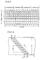
- the data thus read from the memory circuit 4 are in the magnetization pattern as shown in Fig. 8 on the magnetic tape, and are arrayed as shown in Fig. 3.
- no continuous error takes place even if a burst error is caused by interruption of signals in one scanning interval or in the tape travelling direction in half the width of the magnetic tape from the edge thereof, and hence compensation by mean value interpolation is enabled.
- the aforementioned operation for controlling the addresses in writing of the samples in the memory circuit 4 may appropriately be changed for obtaining the magnetization pattern as shown in Fig. 4.
- the present embodiment is characterized in that even samples and odd samples are permutated into groups and that the samples in the respective groups are recorded in regions located at different positions along the direction of scanning from those in continuity therewith as shown in Fig. 8.
- frames l L1 and l L3 including data W L1 and W L3 which are in continuity with the sample W L2 are arrayed in positions separated from the frame l L2 along the tape travelling direction in Fig. 8, and in a region which is different from the region containing frame l L2 .
- the data W L2 and W L1 are separated from each other by a distance X 2 , and no continuous sample error is caused by a burst error in the tape travelling direction extending over a width smaller than the length X 2 .
- X 2 ( ⁇ /2 - 1)X 1 / ⁇
- 200 to 300 frames are generally recorded in one scanning interval, and hence X 2 ⁇ X 1 /2, and hence no continuous sample error takes place even if an error is caused in the tape travelling direction over about half the width of the magnetic tape.
- no continuous sample error takes place by signal interruption caused in one scanning interval, and hence compensation by mean value interpolation is enabled.
- Fig. 9 is an illustration showing another example of the sample array. Although the frame arrangement of the left channel in the sample array as shown in Fig. 9 is different in order from that shown in Fig. 8, a similar effect is obtained also by such an array as a matter of course.
- the magnetization pattern as shown in Fig. 9 can be implemented by simply changing the address control circuits 5 and 16 as shown in Fig. 5.
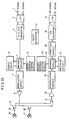
- Fig. 10 is a schematic block diagram showing another embodiment of the present invention
- Fig. 11 is a schematic block diagram of a memory address control circuit as shown in Fig. 10.
- a rotary head-type PCM magnetic recorder/reproducer as shown in Fig. 10 is substantially identical to that shown in Fig. 5 except that a correction circuit 22 is provided between a memory circuit 15 and a D-A converter circuit 18 of the reproducing system and a memory address control circuit 51 is structured as shown in Fig. 11.
- the correction circuit 22 is adapted to perform correction by the aforementioned mean value interpolation of samples not corrected though errors are detected.
- the memory address control circuit 51 comprises a sample writing address generator circuit 501, a first coding address generator circuit 502, a data reading address generator circuit 503, a second coding address generator circuit 506, a second selector 507 for receiving and selectively outputting the outputs from the first and second coding address generator circuits 502 and 506 and a first selector 504 for receiving the outputs from the sample writing address generator circuit 501, the data reading address generator circuit 503 and the second selector 507 and selectively outputting the same at an address output terminal 505.
- Fig. 12 is a timing chart showing operation of the memory circuits as shown in Fig. 10.
- the rotary head-type PCM magnetic recorder/reproducer performs two-head recording/reproducing operation by 90° tape winding, and hence signal recording/reproducing intervals of 90° and pause intervals of 90° alternately appear in the recorded/reproduced waveforms as shown in Fig. 12(a).
- a signal recording/reproducing interval of 90° corresponds to recording/reproducing operation in one scanning interval.
- signals for one scanning interval to be read in a reading interval RD for subsequent reading from the memory circuit 4 are encoded in an encoding interval EN to be read in the reading interval RD. Then the signals for the remaining scanning interval are encoded in the subsequent encoding interval EN, to be read in the reading interval RD.
- Fig. 12(c) Shown in Fig. 12(c) is the operation of the memory circuit 15 in a reproducing operation.
- the writing interval WT the reproduced sample signals for one scanning interval are written in the memory circuit 15, and are decoded in a subsequent decoding interval DE to be written in the memory circuit 15.
- the sample signals for the remaining scanning interval are written in the memory circuit 15 in the subsequent writing interval WT, to be decoded in the subsequent decoding interval DE.
- the decoded samples for two scanning intervals are read in the reading interval RD.
- the samples supplied as W L0 , W R0 , W L1 , ... are subjected to memory address control by the sample writing address generator circuit 501 of the memory address control circuit 51 and written in the memory circuit 15, to be in the array as shown in Fig. 12.
- Fig. 13 is an illustration showing an example of samples stored in the memory circuits as shown in Fig. 10.
- Fig. 13 is different from Fig. 7 in that 26 words are stored as error correction codes in addition to 32 samples of the left and right channels as data for two scanning intervals.
- the encoded data of frame addresses of 0 to 8 are subsequently read in order of frame numbers by the data reading address generator circuit 503 of the memory address control circuit 51 in the unit of frames, with a frame l P0 of the error correction code being read after a frame number 3 to be inserted between intervals La and Rb, thereby recorded in the magnetic tape.
- the samples for the remaining scanning interval are similarly encoded to be recorded in the adjacent scanning interval.
- continuous samples in the respective groups are thus distributed in two scanning intervals, the error correction codes are completed with respect to data for one scanning interval to be recorded in the magnetic tape, and are not extended over two scanning intervals.
- the data are written in the memory circuit 15 in the unit of frames contrary to the recording operation, and are corrected by the error correction codes to be subsequently read as W L0 , W R0 , W L1 , ...
- the error correction codes are completed in one scanning interval as hereinabove described, and hence the samples can be decoded upon reading of the data for one scanning interval.
- This operation is identical to that hereinabove described with reference to Fig. 12, and since data for two scanning intervals are gathered in codes extended over two scanning intervals, the data must be decoded with respect to two scanning intervals in the subsequent decoding interval of 90°.
- the data are decoded per scanning interval in the present embodiment, and hence the clock rate required for encoding and decoding of the data is not increased by data interleaving for two scanning intervals.
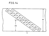
- Fig. 14 illustrates the magnetization pattern recorded on the magnetic tape by the memory circuit structure as shown in Fig. 13.
- symbol X 1 indicates the width of the magnetic tape and symbol X 2 indicates the width of the burst error capable of correction by mean value interpolation.
- reading addresses in recording operation are so controlled that frames l P0 and l P5 of error correction codes are located in the middle of one scanning interval, whereas the frames l P0 and l P5 may be located in any position of the scanning interval.
Description
Claims (54)
- A rotary head type magnetic recording apparatus for recording digital signals successively input in a unit of time in inclined tracks on a recording medium, the digital signals being arranged in an input sequence (WL0,WR0,WL1,WR1, ...) comprising successive words, whereby the apparatus is suitable for recording signals allotted to first and second channels with each channel represented by interleaved odd and even words and the words of the first channel alternating with the words of the second channel;wherein the recording signal processing means (4,5) is arranged such that:wherein each of said tracks includes first and second regions positioned in respective halves in the longitudinal direction of the track, said first region including a plurality of subregions (lL0,lL2,lL4,lL6;lR0,lR2,lR4,lR6) at different positions along the length thereof, with the subregions ordered in succession from the end of the region remotest from the center of the track to the end closest to the center, said second region including a plurality of subregions (lR1, lR3, lR5, lR7; lL1, lL3, lL5, lL7) at different positions along the length thereof, with the subregions ordered in succession from the end of the region closest to the center of the track to the end remotest from the center, said magnetic recording apparatus comprising recording signal processing means (4,5) for arranging said digital signals input in the unit of time so that they are recorded on first and second tracks; anda first word group including a plurality of words (WL0,WL2,WL4,WL6) each of whose position within the input sequence is 4nth (n is an integer) is recorded on the first region of said first track, the position within the input sequence of the first input word being 0th, a second word group including a plurality of words (WR0,WR2,WR4,WR6) each of whose position within the input sequence is 4n+1th is recorded on the first region of said second track, a third word group including a plurality of words (WL1,WL3,WL5,WL7) each of whose position within the input sequence is 4n+2th is recorded on the second region of said second track, and a fourth word group including a plurality of words (WR1,WR3,WR5,WR7) each of whose position within the input sequence is 4n+3th is recorded on the second region of said first track; andthe words of each word group are disposed in respective subregions in order of input sequence number, so that higher-numbered words are disposed in higher-ordered subregions.
- Apparatus as claimed in claim 1, wherein the recording signal processing means (4,5) is arranged such that:a plurality of further first word groups, each including a plurality of words (WL8,WL10,WL12,WL14;WL16, WL18,WL20,WL22;etc.) each of whose position within the input sequence is 4nth, are also recorded on the first region of said first track, each word (e.g. WL8) of each first word group being recorded in a respective subregion (lL0) with words (WL0,WL16, etc.) of other first word groups;a plurality of further second word groups, each including a plurality of words (WR8,WR10,WR12,WR14;WR16,WR18,WR20,WR22;etc.) each of whose position within the input sequence is 4n+1th, are also recorded on the first region of said second track, each word (e.g. WR8) of each second word group being recorded in a respective subregion (LR0) with words (WR0,WR16,etc.) of other second word groups;a plurality of further third word groups, each including a plurality of words (WL9,WL11,WL13,WL15;WL17,WL19,WL21,WL23;etc.) each of whose position within the input sequence is 4n+2th, are also recorded on the second region of said second track, each word (e.g. WL9) of each third word group being recorded in a respective subregion (lL1) with words (WL1, WL17,etc.) of other third word groups; anda plurality of further fourth word groups, each including a plurality of words (WR9,WR11,WR13,WR15;WR17,WR19,WR21,WR23; etc.) each of whose position within the input sequence is 4n+3th, are also recorded on the second region of said first track, each word (e.g. WR9) of each fourth word group being recorded in a respective subregion (lR1) with words (WR1,WR17,etc.) of other fourth word groups.
- Apparatus as claimed in claim 2, wherein, within each subregion (e.g. lL0) of each first region, the words (WL0,WL8,WL16,WL24) are arranged in order of input sequence number, such that higher-numbered words are located closer to that end of the subregion closest to the track center, and, within each subregion (e.g. lR1) of each second region, the words (WR1,WR9,WR17,WR25) are arranged in order of input sequence number, such that higher-numbered words are located closer to that end of the subregion furthest from the track center.
- Apparatus as claimed in any preceding claim, wherein the first region of each track is disposed in the first half of the track to be recorded, and the second region is disposed in the other half.
- Apparatus as claimed in any preceding claim, wherein the first and second tracks are adjacent tracks.
- Apparatus as claimed in any preceding claim, wherein the recording signal processing means (4,5) is arranged to record redundant signals for enabling correction of errors in the digital signals recorded on a track, said redundant signals all being recorded on the respective track.
- Apparatus as claimed in claim 6, wherein at least part of said redundant signals are recorded in a region at the center of the respective track.
- Apparatus as claimed in claim 7, wherein said redundant signals also comprise redundant signals (CL0, CL1, CR0, CR1, etc.) each enabling correction of digital signals recorded in a respective subregion, and each disposed in said respective subregion.
- Apparatus as claimed in any preceding claim, the apparatus further comprising means (10,11) for reproducing recorded digital signals, and reproduced signal processing means (15,16) for permuting said reproduced digital signals so as to output the signals in accordance with their original input sequence.
- Apparatus as claimed in any preceding claim, wherein the first track is recorded before the second track.
- A rotary head type magnetic reproducing apparatus for reproducing digital signals from inclined tracks on a recording medium, each of said tracks including first and second regions positioned in respective halves in the longitudinal direction of the track, said first region including a plurality of subregions (lL0,lL2,lL4,lL6; lR0,lR2,lR4,lR6) at different positions along the length thereof, with the subregions ordered in succession from the end of the region remotest from the center of the track to the end closest to the center, said second region including a plurality of subregions (lR1,lR3,lR5,lR7;lL1,lL3,lL5,lL7) at different positions along the length thereof, with the subregions ordered in succession from the end of the region closest to the center of the track to the end remotest from the center, said magnetic reproducing apparatus comprising reproduced signal processing means (15,16) for rearranging digital signals reproduced from first and second tracks into a desired output sequence (WL0,WR0,WL1,WR1, ...) comprising successive words, whereby the apparatus is suitable for reproducing signals allotted to first and second channels with each channel represented in the output sequence by words of the first channel alternating with those of the second channel, and with the words of each channel comprising interleaved odd and even words; and
wherein the reproduced signal processing means (15,16) is arranged such that:a first word group including a plurality of words (WL0,WL2,WL4,WL6) each of whose position within the output sequence is 4nth (n is an integer) is reproduced from the first region of said first track, the position within the output sequence of the first output word being 0th, a second word group including a plurality of words (WR0,WR2,WR4,WR6) each of whose position within the output sequence is 4n+1th is reproduced from the first region of said second track, a third word group including a plurality of words (WL1,WL3,WL5,WL7) each of whose position within the output sequence is 4n+2th is reproduced from the second region of said second track, and a fourth word group including a plurality of words (WR1,WR3,WR5,WR7) each of whose position within the output sequence is 4n+3th is reproduced from the second region of said first track; andthe words of each word group are reproduced from respective subregions in which they are disposed in order of output sequence number, so that higher-numbered words are disposed in higher-ordered subregions. - Apparatus as claimed in claim 11, wherein the reproduced signal processing means (15,16) is arranged such that:a plurality of further first word groups, each including a plurality of words (WL8,WL10,WL12,WL14;WL16,WL18,WL20,WL22; etc.) each of whose position within the output sequence is 4nth, are also reproduced from the first region of said first track, each word (e.g. WL8) of each first word group being reproduced from a respective subregion (lL0) with words (WL0,WL16,etc.) of other first word groups;a plurality of further second word groups, each including a plurality of words (WR8,WR10,WR12,WR14;WR16,WR18,WR20,WR22;etc.) each of whose position within the output sequence is 4n+1th, are also reproduced from the first region of said second track, each word (e.g. WR8) of each second word group being reproduced from a respective subregion (lR0) with words (WR0,WR16,etc.)of other second word groups;a plurality of further third word groups, each including a plurality of words (WL9,WL11,WL13,WL15;WL17,WL19,WL21,WL23;etc.) each of whose position within the output sequence is 4n+2th, are also reproduced from the second region of said second track, each word (e.g. WL9) of each third word group being reproduced from a respective subregion (lL1) with words (WL1,WL17,etc.) of other third word groups; anda plurality of further fourth word groups, each including a plurality of words (WR9,WR11,WR13,WR15;WR17,WR19,WR21,WR23;etc.) each of whose position within the output sequence is 4n+3th, are also reproduced from the second region of said first track, each word (e.g. WR9) of each fourth word group being reproduced from in a respective subregion (lR1) with words (WR1,WR17,etc.) of other fourth word groups.
- Apparatus as claimed in claim 12, wherein, within each subregion (e.g. lL0) of each first region, the words (WL0,WL8,WL16,WL24) are arranged in order of output sequence number, such that higher-numbered words are located closer to that end of the subregion closest to the track center, and, within each subregion (e.g. lR1) of each second region, the words (WR1,WR9,WR17,WR25) are arranged in order of output sequence number, such that higher-numbered words are located closer to that end of the subregion furthest from the track center.
- Apparatus as claimed in any one of claims 11 to 13, wherein the first region of each track is disposed in the first half of the track from which signals are reproduced, and the second region is disposed in the other half.
- Apparatus as claimed in any one of claims 11 to 14, wherein the first and second tracks are adjacent tracks.
- Apparatus as claimed in any one of claims 11 to 15, wherein the reproduced signal processing means (15,16) is arranged to reproduce redundant signals for enabling correction of errors in the digital signals reproduced from a track, said redundant signals all being reproduced from the respective track.
- Apparatus as claimed in claim 16, wherein at least part of said redundant signals are reproduced from a region at the center of the respective track.
- Apparatus as claimed in claim 17, wherein further redundant signals (CL0, CL1, CR0, CR1, etc.) each enabling correction of digital signals recorded in a respective subregion, are each reproduced from said respective subregion.
- Apparatus as claimed in any one of claims 11 to 18, wherein the first track is reproduced before the second track.
- A method of recording digital signals successively input in a unit of time in inclined tracks on a recording medium, the digital signals being arranged in an input sequence (WL0, WR0, WL1, WR1, ...) comprising successive words, whereby the method is suitable for recording signals allotted to first and second channels with each channel represented in the input sequence by interleaved odd and even words and the words of the first channel alternating with those of the second other channel, each of said tracks including first and second regions positioned in respective halves in the longitudinal direction of the track, said first region including a plurality of subregions (lL0,lL2,lL4,lL6;lR0,lR2,lR4,lR6) at different positions along the length thereof, with the subregions ordered in succession from the end of the region remotest from the center of the track to the end closest to the center, said second region including a plurality of subregions (lR1,lR3,lR5,lR7;lL1,lL3,lL5,lL7) at different positions along the length thereof, with the subregions ordered in succession from the end of the region closest to the center of the track to the end remotest from the center, said method comprising the step of arranging said digital signals input in the unit of time so that they are recorded on first and second tracks;
characterised in that:a first word group including a plurality of words (WL0,WL2,WL4,WL6) each of whose position within the input sequence is 4nth (n is an integer) is recorded on thefirst region of said first track, the position within the input sequence of the first input word being 0th, a second word group including a plurality of words (WR0,WR2,WR4,WR6) each of whose position within the input sequence is 4n+1th is recorded on the first region of said second track, a third word group including a plurality of words (WL1,WL3,WL5,WL7) each of whose position within the input sequence is 4n+2th is recorded on the second region of said second track, and a fourth word group including a plurality of words (WR1,WR3,WR5,WR7) each of whose position within the input sequence is 4n+3th is recorded on the second region of said first track; andthe words of each word group are disposed in respective subregions in order of input sequence number, so that higher-numbered words are disposed in higher-ordered subregions. - A method as claimed in claim 20, wherein:a plurality of further first word groups, each including a plurality of words (WL8,WL10,WL12,WL14;WL16,WL18,WL20,WL22;etc.) each of whose position within the input sequence is 4nth, are also recorded on the first region of said first track, each word (e.g. WL8) of each first word group being recorded in a respective subregion (lL0) with words (WL0,WL16,etc.) of other first word groups;a plurality of further second word groups, each including a plurality of words (WR8,WR10,WR12,WR14;WR16,WR18,WR20,WR22;etc.) each of whose position within the input sequence is 4n+1th, are also recorded on the first region of said second track, each word (e.g. WR8) of each second word group being recorded in a respective subregion (lR0) with words (WR0,WR16,etc.) of other second word groups;a plurality of further third word groups, each including a plurality of words (WL9, WL11,WL13,WL15;WL17,WL19,WL21,WL23;etc.) each of whose position within the input sequence is 4n+2th, are also recorded on the second region of said second track, each word (e.g. WL9) of each third word group being recorded in a respective subregion (lL1) with words (WL1,WL17,etc.) of other third word groups; anda plurality of further fourth word groups, each including a plurality of words (WR9,WR11,WR13,WR15;WR17,WR19,WR21,WR23;etc.) each of whose position within the input sequence is 4n+3th, are also recorded on the second region of said first track, each word (e.g. WR9) of each fourth word group being recorded in a respective subregion (lR1) with words (WR1,WR17,etc.) of other fourth word groups.
- A method as claimed in claim 21, wherein, within each subregion (e.g. lL0) of each first region, the words (WL0,WL8,WL16,WL24) are arranged in order of input sequence number, such that higher-numbered words are located closer to that end of the subregion closest to the track center, and, within each subregion (e.g. lR1) of each second region, the words (WR1,WR9,WR17,WR25) are arranged in order of input sequence number, such that higher-numbered words are located closer to that end of the subregion furthest from the track center.
- A method as claimed in any one of claims 20 to 22, wherein the first region of each track is disposed in the first half of the track to be recorded, and the second region is disposed in the other half.
- A method as claimed in any one of claims 20 to 23, wherein the first and second tracks are adjacent tracks.
- A method as claimed in any one of claims 20 to 24, including the step of recording redundant signals for enabling correction of errors in the digital signals recorded on a track, said redundant signals all being recorded on the respective track.
- A method as claimed in claim 25, wherein at least part of said redundant signals are recorded in a region at the center of the respective track.
- A method as claimed in claim 26, wherein further redundant signals (CL0, CL1, CR0, CR1, etc.) each enabling correction of digital signals recorded in a respective subregion, are each also recorded in said respective subregion.
- A method as claimed in any one of claims 20 to 27, wherein the first track is recorded before the second track.
- A method of recording and reproducing digital signals, the method including recording the signals using a method as claimed in any one of claims 20 to 28, and reproducing the recorded signals by reproducing the first, second, third and fourth word groups, and rearranging the words so as to output the signals in accordance with their original input sequence.
- A method of reproducing digital signals from inclined tracks on a recording medium, each of said tracks including first and second regions positioned in respective halves in the longitudinal direction of the track, said first region including a plurality of subregions (LL0,lL2,lL4,lL6;lR0,lR2,lR4,lR6) at different positions along the length thereof, with the subregions ordered in succession from the end of the region remotest from the center of the track to the end closest to the center, said second region including a plurality of subregions (lR1,lR3,lR5,lR7;lL1,lL3,lL5,lL7) at different positions along the length thereof, with the subregions ordered in succession from the end of the region closest to the center of the track to the end remotest from the center, said method comprising rearranging digital signals reproduced from first and second tracks into a desired output sequence (WL0,WR0,WL1,WR1, ...) comprising successive words, whereby the method is suitable for reproducing signals allotted to first and second channels with ech channel represented in the output sequence by words of the first channel alternating with those of the second channel, and with the words of each channel comprising interleaved odd and even words;
wherein:a first word group including a plurality of words (WL0,WL2,WL4,WL6) each of whose position within the output sequence is 4nth (n is an integer) is reproduced from the first region of said first track, the position within the output sequence of the first output word being 0th, a second word group including a plurality of words (WR0,WR2,WR4,WR6) each of whose position within the output sequence is 4n+1th is reproduced from the first region of said second track, a third word group including a plurality of words (WL1,WL3,WL5,WL7) each of whose position within the output sequence is 4n+2th is reproduced from the second region of said second track, and a fourth word group including a plurality of words (WR1,WR3,WR5,WR7) each of whose position within the output sequence is 4n+3th is reproduced from the second region of said first track; andthe words of each word group are reproduced from respective subregions in which they are disposed in order of output sequence number, so that higher-numbered words are disposed in higher-ordered subregions. - A method as claimed in claim 30, wherein:a plurality of further first word groups, each including a plurality of words (WL8,WL10,WL12,WL14;WL16,WL18,WL20,WL22;etc.) each of whose position within the output sequence is 4nth, are also reproduced from the first region of said first track, each word (e.g. WL8) of each first word group being reproduced from a respective subregion (lL0) with words (WL0,WL16,etc.) of other first word groups;a plurality of further second word groups, each including a plurality of words (WR8, WR10,WR12,WR14;WR16,WR18,WR20, WR22;etc.) each of whose position within the output sequence is 4n+1th, are also reproduced from the first region of said second track, each word (e.g. WR8) of each second word group being reproduced from a respective subregion (lR0) with words (WR0,WR16,etc.) of other second word groups;a plurality of further third word groups, each including a plurality of words (WL9,WL11,WL13,WL15;WL17,WL19,WL21,WL23;etc.) each of whose position within the output sequence is 4n+2th, are also reproduced from the second region of said second track, each word (e.g. WL9) of each third word group being reproduced from a respective subregion (lL1) with words (WL1,WL17,etc.) of other third word groups; anda plurality of further fourth word groups, each including a plurality of words (WR9,WR11,WR13,WR15;WR17,WR19,WR21,WR23;etc.) each of whose position within the output sequence is 4n+3th, are also reproduced from the second region of said first track, each word (e.g. WR9) of each fourth word group being reproduced from in a respective subregion (lR1) with words (WR1,WR17,etc.) of other fourth word groups.
- A method as claimed in claim 31, wherein, within each subregion (e.g. lL0) of each first region, the words (WL0,WL8,WL16,WL24) are arranged in order of output sequence number, such that higher-numbered words are located closer to that end of the subregion closest to the track center, and, within each subregion (e.g. LR1) of each second region, the words (WR1,WR9,WR17,WR25) are arranged in order of output sequence number, such that higher-numbered words are located closer to that end of the subregion furthest from the track center.
- A method as claimed in any one of claims 30 to 32, wherein the first region of each track is disposed in the first half of the track from which signals are reproduced, and the second region is disposed in the other half.
- A method as claimed in any one of claims 30 to 33, wherein the first and second tracks are adjacent tracks.
- A method as claimed in any one of claims 30 to 34, including the step of reproducing redundant signals for enabling correction of errors in the digital signals reproduced from a track, said redundant signals all being reproduced from the respective track.
- A method as claimed in claim 35, wherein at least part of said redundant signals are reproduced from a region at the center of the respective track.
- A method as claimed in claim 36, wherein further redundant signals (CL0, CL1, CR0, CR1, etc.) each enabling correction of digital signals recorded in a respective subregion, are each reproduced from said respective subregion.
- A method as claimed in any one of claims 30 to 37, wherein the first track is reproduced before the second track.
- A rotary head type magnetic recording apparatus for recording first and second channels (A,B) of digital signals on a recording medium while forming slanting tracks, comprising:coding means (6) for encoding digital signals to be recorded on one of said tracks for generating redundant signals for indicating errors in said digital signals;signal processing means (4,5) for separating samples of each of said two channels (A,B) inputted in a unit of time into even input samples and odd input samples, the even input samples including the earliest sample in said time unit, for rearranging the samples such that all the samples of said two channels are arranged in two tracks, and for supplying said digital signals and said redundant signals so as to include all redundant signals in the track including the digital signals from which said redundant signals are generated; andrecording means (10,11) for successively recording the digital signals and the redundant signals supplied from said signal processing means on the recording medium; whereineach of said tracks comprises at least a first region including the center of the track and second and third regions positioned on respective sides of the first region, andsaid signal processing means (4,5) comprises means for arranging the even samples (Aa in Fig. 3) of said first channel to be recorded on the second region of one of said first and second tracks such that the general trend is for higher-numbered samples to be disposed closer to the first region than lower-numbered samples, the odd samples (Bb) of said second channel to be recorded on the third region of said one track such that the general trend is for lower-numbered samples to be disposed closer to the first region than higher-numbered samples, the even samples (Ba) of said second channel to be recorded in the second region of the other of said first and second tracks in the same sample order as the even samples (Aa) of said first channel, and the odd samples (Ab) of said first channel to be recorded on the third region of said other track in the same sample order as the odd samples (Bb) of said second channel, and for arranging at least part of the redundant signals for the digital signals of said one track to be recorded on the first region of said one track, and arranging at least part of said redundant signals for the digital signals of said other track to be recorded on the first region of said other track.
- Apparatus as claimed in claim 39, the apparatus further comprising means (10,11) for reproducing recorded digital signals and reproduced signal processing means (15,16) for permuting said reproduced digital signals so as to output the signals of each channel in order of sample numbers thereof.
- A rotary head type magnetic reproducing apparatus for reproducing first and second channels (A,B) of digital signals, the digital signals of each channel being represented by odd and even samples having an original order, while successively scanning slanting tracks formed on a recording medium, each of said tracks comprising at least a first region including the center of the track and second and third regions on respective sides of the first region,said apparatus being arranged for reproducing samples of a unit of time of said two channels recorded on said second and third regions of first and second tracks, the even samples of each channel including the earliest sample in said time unit, and for reproducing from the first region of each track at least part of redundant signals for indicating errors in the digital signals of the respective track, all of which redundant signals are recorded in the respective track, and the apparatus comprising:reproducing means (10,11) for reproducing the signals while scanning said tracks;decoding means (17) responsive to the redundant signals for determining errors in the digital signals of each track; andreproduced signal processing means (15,16) for rearranging the order of samples from the first and second tracks and outputting the samples in each channel as digital signals,said reproduced signal processing means (15,16) including means for recovering the original order of the samples from reproduced signals including even samples (Aa in Fig. 3) of said first channel reproduced from the second region of one of said first and second tracks, odd samples (Bb) of said second channel reproduced from the third region of said one track, even samples (Ba) of said second channel reproduced from the second region of the other of said tracks, and odd samples (Ab) of said first channel reproduced from the third region of said other track, wherein the even samples (Ba) of said second channel are re-arranged in the same manner as the even samples (Aa) of said first channel and such that the general trend is for higher-numbered samples to be recovered from positions closer to the first region than lower-numbered samples, and wherein odd samples (Ab) of said first channel are re-arranged in the same manner as the odd samples (Bb) of said second channel and such that the general trend is for lower-numbered samples to be recovered from positions closer to the first region than higher-numbered samples.
- A method of rotary head type magnetic recording for recording first and second channels (A,B) of digital signals on a recording medium while forming slanting tracks,the method comprising the steps of:wherein each of said tracks includes at least a first region including the center of the track and second and third regions positioned on respective sides of said first region,separating samples of each of said first and second channels (A,B) inputted in a unit of time into even input samples, which include the earliest sample in said time unit, and odd input samples,arranging all the samples of a time unit for said channels in said second and third regions of first and second tracks,recording the even samples (Aa in Fig. 3) of said first channel in a group in the second region of one of said first and second tracks such that the general trend is for higher-numbered samples to be disposed closer to the first region than lower-numbered samples,recording the odd samples (Bb) of said second channel in a group on the third region of said one track such that the general trend is for lower-numbered samples to be disposed closer to the first region than higher-numbered samples,recording the even samples (Ba) of said second channel in a group on the second region of the other of said first and second tracks to have the same sample order as the even samples (Aa) of said first channel,recording the odd samples (Ab) of said first channel in a group on the third region of said other track to have the same sample order as the odd samples (Bb) of said second channel, andrecording on one track a complete set of redundant signals for indicating errors in the digital signals arranged on said one track, at least part of the redundant signals being recorded on said first region.
- A method as claimed in claim 42, wherein said one of said first and second tracks is recorded before the other of said first and second tracks.
- A method as claimed in claim 42 or 43, wherein the second region of each track is disposed in the first half of the track to be recorded, and the third region is disposed in the other half.
- A magnetic recording and reproducing apparatus for recording and reproducing data, the apparatus comprising means for recording data using a recording method according to claim 42, 43 or 44, and for reproducing the data by reproducing the even samples (Aa) of the first channel from the second region of said one track and the odd samples (Bb) of the second channel from the third region of said one track, and for reproducing the even samples (Ba) of the second channel from the second region of said other track and the odd samples (Ab) of the first channel from the third region of said other track, and for outputting the samples in an order rearranged with respect to the order in which the samples are recorded on said tracks so as to obtain the original order thereof.
- A method of rotary head type magnetic reproduction for reproducing first and second channels (A,B) of digital signals while successively scanning slanting tracks formed on a recording medium, the digital signals of each channel being represented by odd and even samples having an original order, and for reproducing from each track redundant signals indicative of errors in the digital signals recorded on the respective track, at least part of the redundant signals being recorded in a first region of the track, which first region includes the center of the track, wherein each track further includes second and third regions positioned on respective sides of the first region, samples of a unit of time of two channels being arranged on said second and third regions of first and second tracks; whereinthe method comprising the steps of:even samples (Aa in Fig. 3) of said first channel are arranged in the same sample order as the even samples (Ba) of said second channel and such that the general trend is for higher-numbered samples to be disposed closer to the first region than lower-numbered samples, and odd samples (Ab) of said first channel are arranged in the same sample order as the odd samples (Bb) of said second channel and such that the general trend is for lower-numbered samples to be disposed closer to the first region than higher-numbered samples;reproducing even samples (Aa) of the first channel from the second region of one of said first and second tracks,reproducing odd samples (Bb) of the second channel from the third region of said one track,reproducing even samples (Ba) of said second channel from the second region of the other of said first and second tracks,reproducing odd samples (Ab) of said first channel from the third region of said other track,rearranging the reproduced samples to their original order; anddetermining errors in the digital signals on each track using said redundant signals recorded therewith on said track.
- A rotary head type magnetic recording apparatus for recording digital signals successively input in a unit of time in inclined tracks on a recording medium, the digital signals being arranged in an input sequence (WL0,WR0,WL1,WR1, ...) comprising successive words, whereby the apparatus is suitable for recording signals allotted to first and second channels with each channel represented by interleaved odd and even words and the words of the first channel alternating with those of the second channel, each of said tracks including first and second regions positioned in respective halves in the longitudinal direction of the track, said first and second regions each including a plurality of subregions (lL0,lL2,lL4,lL6;lR0,lR2,lR4,lR6; lR1,lR3,lR5,lR7;lL1,lL3,lL5,lL7) at different positions along the length thereof, said magnetic recording apparatus comprising recording signal processing means (4,5) for arranging said digital signals input in the unit of time so that they are recorded on first and second tracks;
whereby the recording signal processing means (4,5) is arranged to record respective word groups in respective regions, such that:a first word group including a plurality of words (WL0,WL2,WL4,WL6) each of whose position within the input sequence is 4nth (n is an integer) is recorded on the first region of said first track, the position within the input sequence of the first input word being 0th, a second word group including a plurality of words (WR0,WR2,WR4,WR6) each of whose position within the input sequence is 4n+1th is recorded on the first region of said second track [or alternatively the second region of said first track], a third word group including a plurality of words (WL1,WL3,WL5,WL7) each of whose position within the input sequence is 4n+2th is recorded on the second region of said second track, and a fourth word group including a plurality of words (WR1,WR3,WR5,WR7) each of whose position within the input sequence is 4n+3th is recorded on the second region of said first track [or alternatively the first region of said second track];the words of each word group being disposed in respective subregions;the recording signal processing means (4,5) being arranged to record redundant signals for enabling correction of errors in the digital signals recorded on a track, said redundant signals all being recorded on the respective track, said redundant signals comprising first redundant signals (P0-P4; P5-P9) recorded in a region at the center of the respective track and second redundant signals (CL0, CL1, CR0, CR1, etc.) each for enabling correction of digital signals recorded in a respective subregion and each disposed in said respective subregion. - Apparatus as claimed in claim 47, wherein each second redundant signal is recorded at an end of a respective subregion.
- A rotary head type magnetic reproducing apparatus for reproducing digital signals from inclined tracks on a recording medium, each of said tracks including first and second regions positioned in respective halves in the longitudinal direction of the track, said first and second regions each including a plurality of subregions (lL0,lL2,lL4,lL6;lR0,lR2,lR4,lR6;whereby the reproduced signal processing means (15,16) is arranged such that:lR1,lR3,lR5,lR7;lL1,lL3,lL5,lL7) at different positions along the length thereof, said magnetic reproducing apparatus comprising reproducing signal processing means (15,16) for re-arranging digital signals reproduced from first and second tracks into a desired output sequence (WL0,WR0,WL1,WR1, ...) comprising successive words, whereby the apparatus is suitable for reproducing signals allotted to first and second channels with each channel represented in the output sequence by words of the first channel alternating with those of the second channel, and with the words of each channel comprising interleaved odd and even words;a first word group including a plurality of words (WL0,WL2,WL4,WL6) each of whose position within the input sequence is 4nth (n is an integer) is reproduced from the first region of said first track, the position within the input sequence of the first input word being 0th, a second word group including a plurality of words (WR0,WR2,WR4,WR6) each of whose position within the input sequence is 4n+1th is reproduced from the first region of said second track [or alternatively the second region of said first track], a third word group including a plurality of words (WL1,WL3,WL5,WL7) each of whose position within the input sequence is 4n+2th is reproduced from the second region of said second track, and a fourth word group including a plurality of words (WR1,WR3,WR5,WR7) each of whose position within the input sequence is 4n+3th is reproduced from the second region of said first track [or alternatively the first region of said second track];the words of each word group being reproduced from respective subregions;the reproduced signal processing means (15,16) being arranged to reproduce redundant signals for enabling correction of errors in the digital signals reproduced from a track, said redundant signals all being reproduced from the respective track, said redundant signals comprising first redundant signals (P0-P4; P5-P9) reproduced from a region at the center of the respective track and second redundant signals (CL0, CL1, CR0, CR1, etc.) each for enabling correction of digital signals reproduced from a respective subregion and each reproduced from said respective subregion.
- Apparatus as claimed in claim 49, wherein each second redundant signal is reproduced from an end of a respective subregion.
- A method of recording digital signals successively input in a unit of time in inclined tracks on a recording medium, the digital signals being arranged in an input sequence (WL0,WR0,WL1,WR1, ...) comprising successive words, whereby the method is suitable for recording signals allotted to first and second channels with each channel represented by interleaved odd and even words and the words of the first channel alternating with those of the second channel, each of said tracks including first and second regions positioned in respective halves in the longitudinal direction of the track, said first and second regions each including a plurality of subregions (lL0,lL2,lL4,1L6;lR0,lR2,lR4,lR6; lR1,lR3,lR5,lR7;lL1,lL3,lL5,lL7) at different positions along the length thereof, the method comprising the step of arranging said digital signals input in the unit of time so that they are recorded on first and second tracks;
whereby:a first word group including a plurality of words (WL0,WL2,WL4,WL6) each of whose position within the input sequence is 4nth (n is an integer) is recorded on the first region of said first track, the position within the input sequence of the first input word being 0th, a second word group including a plurality of words (WR0,WR2,WR4,WR6) each of whose position within the input sequence is 4n+1th is recorded on the first region of said second track [or alternatively the second region of said first track], a third word group including a plurality of words (WL1,WL3,WL5,WL7) each of whose position within the input sequence is 4n+2th is recorded on the second region of said second track, and a fourth word group including a plurality of words (WR1,WR3,WR5,WR7) each of whose position within the input sequence is 4n+3th is recorded on the second region of said first track [or alternatively the first region of said second track];the words of each word group being disposed in respective subregions;the method further including the step of recording redundant signals for enabling correction of errors in the digital signals recorded on a track, said redundant signals all being recorded on the respective track, said redundant signals comprising first redundant signals (P0-P4; P5-P9) recorded in a region at the center of the respective track and second redundant signals (CL0, CL1, CR0, CR1, etc.) each for enabling correction of digital signals recorded in a respective subregion and each disposed in said respective subregion. - A method as claimed in claim 51, wherein each second redundant signal is recorded at an end of a respective subregion.
- A method of reproducing digital signals from inclined tracks on a recording medium, each of said tracks including first and second regions positioned in respective halves in the longitudinal direction of the track, said first and second regions each including a plurality of subregions (lL0,lL2,lL4,lL6;lR0,lR2,lR4,lR6;
lR1,lR3,lR5,lR7;lL1,lL3,lL5,lL7) at different positions along the length thereof, said method comprising rearranging digital signals reproduced from first and second tracks into a derived output sequence (WL0,WR0,WL1,WR1, ...) comprising successive words, whereby the method is suitable for reproducing signals allotted to first and second channels with each channel represented in the output sequence by words of the first channel alternating with those of the second channel, and with the words of each channel comprising interleaved odd and even words;
whereby:a first word group including a plurality of words (WL0,WL2,WL4,WL6) each of whose position within the input sequence is 4nth (n is an integer) is reproduced from the first region of said first track, the position within the input sequence of the first input word being 0th, a second word group including a plurality of words (WR0,WR2,WR4,WR6) each of whose position within the input sequence is 4n+1th is reproduced from the first region of said second track [or alternatively the second region of said first track], a third word group including a plurality of words (WL1,WL3,WL5,WL7) each of whose position within the input sequence is 4n+2th is reproduced from the second region of said second track, and a fourth word group including a plurality of words (WR1,WR3,WR5,WR7) each of whose position within the input sequence is 4n+3th is reproduced from the second region of said first track [or alternatively the first region of said second track];the words of each word group being reproduced from respective subregions;the reproduced signal processing means (15,16) being arranged to reproduce redundant signals for enabling correction of errors in the digital signals reproduced from a track, said redundant signals all being reproduced from the respective track, said redundant signals comprising first redundant signals (P0-P4; P5-P9) reproduced from a region at the center of the respective track and second redundant signals (CL0, CL1, CR0, CR1, etc.) each for enabling correction of digital signals reproduced from a respective subregion and each reproduced from said respective subregion. - A method as claimed in claim 52, wherein each second redundant signal is reproduced from an end of a respective subregion.
Applications Claiming Priority (7)
| Application Number | Priority Date | Filing Date | Title |
|---|---|---|---|
| JP3213084A JPS60175262A (en) | 1984-02-21 | 1984-02-21 | Rotary head type magnetic recording and reproducing device |
| JP32130/84 | 1984-02-21 | ||
| JP5186684A JPS60195782A (en) | 1984-03-16 | 1984-03-16 | Recorder/reproducer of rotational head type |
| JP51866/84 | 1984-03-16 | ||
| JP64584/84 | 1984-03-30 | ||
| JP6458484A JPS60209973A (en) | 1984-03-30 | 1984-03-30 | Rotary head type recording and reproducing device |
| EP88111726A EP0301399B1 (en) | 1984-02-21 | 1985-02-21 | Magnetic tape having a recording of digital signals and method of producing the same |
Related Parent Applications (2)
| Application Number | Title | Priority Date | Filing Date |
|---|---|---|---|
| EP88111726.1 Division | 1985-02-21 | ||
| EP88111726A Division EP0301399B1 (en) | 1984-02-21 | 1985-02-21 | Magnetic tape having a recording of digital signals and method of producing the same |
Publications (3)
| Publication Number | Publication Date |
|---|---|
| EP0495558A2 EP0495558A2 (en) | 1992-07-22 |
| EP0495558A3 EP0495558A3 (en) | 1994-08-31 |
| EP0495558B1 true EP0495558B1 (en) | 1998-10-21 |
Family
ID=27287594
Family Applications (3)
| Application Number | Title | Priority Date | Filing Date |
|---|---|---|---|
| EP92200452A Expired - Lifetime EP0495558B1 (en) | 1984-02-21 | 1985-02-21 | Method and apparatus for magnetic recording and reproducing |
| EP85301166A Expired EP0155101B2 (en) | 1984-02-21 | 1985-02-21 | Method and apparatus for magnetic recording and reproducing |
| EP88111726A Expired - Lifetime EP0301399B1 (en) | 1984-02-21 | 1985-02-21 | Magnetic tape having a recording of digital signals and method of producing the same |
Family Applications After (2)
| Application Number | Title | Priority Date | Filing Date |
|---|---|---|---|
| EP85301166A Expired EP0155101B2 (en) | 1984-02-21 | 1985-02-21 | Method and apparatus for magnetic recording and reproducing |
| EP88111726A Expired - Lifetime EP0301399B1 (en) | 1984-02-21 | 1985-02-21 | Magnetic tape having a recording of digital signals and method of producing the same |
Country Status (3)
| Country | Link |
|---|---|
| US (7) | US4675754A (en) |
| EP (3) | EP0495558B1 (en) |
| DE (3) | DE3588201T2 (en) |
Families Citing this family (40)
| Publication number | Priority date | Publication date | Assignee | Title |
|---|---|---|---|---|
| US5233480A (en) * | 1984-02-21 | 1993-08-03 | Mitsubishi Denki Kabushiki Kaisha | Magnetic recorder/reproducer |
| JPH07122966B2 (en) * | 1984-03-19 | 1995-12-25 | 株式会社日立製作所 | Recording method and reproducing method of rotary head type PCM recorder |
| US4807055A (en) * | 1985-09-11 | 1989-02-21 | Pioneer Electronic Corporation | Multi-speed magnetic recording playback |
| JPH083882B2 (en) * | 1986-08-21 | 1996-01-17 | ソニー株式会社 | Digital signal regenerator |
| US4853797A (en) * | 1987-02-26 | 1989-08-01 | Sony Corporation | Fir type digital filter for recording and reproducing apparatus |
| US4890165A (en) * | 1987-04-06 | 1989-12-26 | Canon Kabushiki Kaisha | Image pick-up apparatus for producing video signals of high information density in time base direction |
| US4807287A (en) * | 1987-04-06 | 1989-02-21 | Light Signatures, Inc. | Document authentication method |
| US5237461A (en) * | 1987-06-03 | 1993-08-17 | Robert Bosch Gmbh | Method and apparatus for reproducing video data stored on a magnetic tape in a manner facilitating search and slow-motion operation |
| JP2576512B2 (en) * | 1987-06-29 | 1997-01-29 | ソニー株式会社 | Data recorder |
| US5091805A (en) * | 1987-10-27 | 1992-02-25 | Sony Corporation | Apparatus and method for recording and/or reproducing a digital signal |
| EP0323119B1 (en) * | 1987-12-29 | 1994-07-20 | Sony Corporation | Method for transmitting digital data |
| JPH0773363B2 (en) * | 1988-01-21 | 1995-08-02 | パイオニア株式会社 | Signal reproduction processor |
| JPH069108B2 (en) * | 1988-02-05 | 1994-02-02 | ソニーマグネスケール株式会社 | Multi-channel PCM data recording method |
| JP2829963B2 (en) * | 1988-05-16 | 1998-12-02 | ソニー株式会社 | Digital data recording / reproducing device |
| GB2220521B (en) * | 1988-06-07 | 1993-04-28 | Mitsubishi Electric Corp | Digital signal recording method a digital video tape recorder and a recorded tape |
| GB2258751B (en) * | 1988-06-07 | 1993-04-28 | Mitsubishi Electric Corp | Digital signal recording method a digital video tape recorder and a recorded tape |
| JP2661206B2 (en) * | 1988-10-31 | 1997-10-08 | キヤノン株式会社 | Video signal recording device |
| JP2693809B2 (en) * | 1989-03-17 | 1997-12-24 | シャープ株式会社 | Image recording and playback device |
| DE69023808T2 (en) * | 1989-05-12 | 1996-08-08 | Mitsubishi Electric Corp | Method and recording and reproducing apparatus with a rotating head. |
| US5111463A (en) * | 1989-11-09 | 1992-05-05 | Exabyte Corporation | Error correction method and apparatus |
| EP0453229B1 (en) * | 1990-04-17 | 1997-06-18 | Matsushita Electric Industrial Co., Ltd. | Method for transmission of variable length code |
| US5680378A (en) * | 1990-09-27 | 1997-10-21 | Casio Computer Co., Ltd. | Digital recorder for recording/reproducing events formed by dividing audio data in a designated order |
| JP2969187B2 (en) * | 1990-12-28 | 1999-11-02 | カシオ計算機株式会社 | Digital recorder |
| JPH04238160A (en) * | 1991-01-21 | 1992-08-26 | Sony Corp | Signal reproducing device |
| US5323275A (en) * | 1991-01-31 | 1994-06-21 | Sony Corporation | Digital signal recording and/or reproducing apparatus having correlated digital and analog signal level controllers |
| DE4229710B4 (en) * | 1991-09-09 | 2008-06-05 | Samsung Electronics Co., Ltd. | Digital audio data storage system and digital audio system equipped therewith |
| JPH05109196A (en) * | 1991-10-14 | 1993-04-30 | Sony Corp | Recording method |
| JP2948016B2 (en) * | 1992-03-19 | 1999-09-13 | 株式会社日立製作所 | Information recording and playback method |
| US5327182A (en) * | 1992-06-10 | 1994-07-05 | Sony Electronics, Inc. | Method and apparatus for reading photographically recorded digital audio soundtracks |
| JPH07312041A (en) * | 1994-05-17 | 1995-11-28 | Sony Corp | Digital signal reproducing device |
| JP3480057B2 (en) * | 1994-09-12 | 2003-12-15 | ソニー株式会社 | Data recording method, data reproducing method and recording medium |
| EP0748130B1 (en) | 1995-06-05 | 2002-09-25 | Sony Electronics Inc. | Recording and reproducing digital signals |
| JP3252706B2 (en) * | 1995-07-21 | 2002-02-04 | ソニー株式会社 | Video signal reproduction method and apparatus, and signal transmission method and apparatus |
| US6271979B1 (en) * | 1995-08-25 | 2001-08-07 | Sony Corporation | Digital data recording and reproducing apparatus having record overflow determining means |
| US5639585A (en) * | 1995-08-31 | 1997-06-17 | Sony Corporation | System for photographically recording digital data and analog soundtrack, and medium having digital data and analog soundtrack recorded thereon |
| US6049517A (en) | 1996-04-30 | 2000-04-11 | Sony Corporation | Dual format audio signal compression |
| JP3282661B2 (en) * | 1997-05-16 | 2002-05-20 | ソニー株式会社 | Signal processing apparatus and method |
| JPH1198462A (en) * | 1997-09-19 | 1999-04-09 | Hitachi Ltd | Data reproduction device |
| US7406102B2 (en) * | 2002-07-03 | 2008-07-29 | Freescale Semiconductor, Inc. | Multi-mode method and apparatus for performing digital modulation and demodulation |
| KR100624306B1 (en) * | 2004-05-28 | 2006-09-18 | 삼성에스디아이 주식회사 | Scan driving apparatus and having the flat panel display and driving method thereof |
Family Cites Families (26)
| Publication number | Priority date | Publication date | Assignee | Title |
|---|---|---|---|---|
| US4052298A (en) * | 1974-11-26 | 1977-10-04 | Colorkrome, Inc. | Treatment of electrophotographic toner compositions |
| JPS53142208A (en) * | 1977-05-18 | 1978-12-11 | Teac Corp | Method of recording pcm signal |
| CA1106067A (en) * | 1977-07-19 | 1981-07-28 | Katsuhiro Nakamura | Error correction system for differential phase-shift- keying |
| US4142174A (en) * | 1977-08-15 | 1979-02-27 | International Business Machines Corporation | High speed decoding of Reed-Solomon codes |
| US4211997A (en) * | 1978-11-03 | 1980-07-08 | Ampex Corporation | Method and apparatus employing an improved format for recording and reproducing digital audio |
| JPS5573909A (en) * | 1978-11-28 | 1980-06-04 | Matsushita Electric Ind Co Ltd | Signal processor |
| JPS56124108A (en) * | 1980-02-29 | 1981-09-29 | Matsushita Electric Ind Co Ltd | Digital signal recording system |
| DE3040004A1 (en) * | 1979-10-24 | 1981-05-07 | Matsushita Electric Industrial Co., Ltd., Kadoma, Osaka | METHOD AND DEVICE FOR CODING CHECK WORDS OF LOW REDUNDANCY FROM ORIGIN DATA |
| GB2073935B (en) * | 1980-04-11 | 1983-12-21 | Rca Corp | Tape format to facilitate error concealment and apparatus for recording and/or replaying same |
| FR2480217A1 (en) * | 1980-04-11 | 1981-10-16 | Labavia | IMPROVEMENTS IN RETARDER CONTROL DEVICES |
| JPS58153213A (en) * | 1982-03-05 | 1983-09-12 | Matsushita Electric Ind Co Ltd | Recording system of digital signal |
| JPS58166506A (en) * | 1982-03-25 | 1983-10-01 | Sony Corp | Magnetic recording device |
| JPS58185012A (en) * | 1982-04-23 | 1983-10-28 | Sony Corp | Recorder of pcm signal |
| JPS58188314A (en) * | 1982-04-26 | 1983-11-02 | Sony Corp | Recorder of pcm data |
| US4506306A (en) * | 1982-11-08 | 1985-03-19 | Eastman Kodak Company | Interleaved redundancy in data recording |
| JPS59110012A (en) * | 1982-12-14 | 1984-06-25 | Mitsubishi Electric Corp | Recording system for pcm signal |
| JPS59119519A (en) * | 1982-12-27 | 1984-07-10 | Sony Corp | Recorder of pcm signal |
| JPS59124108A (en) * | 1982-12-28 | 1984-07-18 | Toshiba Corp | Radiator for oil-immersed electric apparatus |
| JPH0697543B2 (en) * | 1983-01-31 | 1994-11-30 | ソニー株式会社 | Recording device for PCM data |
| JPS59177706A (en) * | 1983-03-25 | 1984-10-08 | Mitsubishi Electric Corp | Rotary head type pulse code modulation magnetic recording and reproducing device |
| JPH077581B2 (en) * | 1983-10-26 | 1995-01-30 | 三菱電機株式会社 | Rotating head type PCM magnetic recording / reproducing apparatus |
| JPH0828055B2 (en) * | 1984-02-17 | 1996-03-21 | ソニー株式会社 | Recording method of PCM data |
| JPH07122966B2 (en) * | 1984-03-19 | 1995-12-25 | 株式会社日立製作所 | Recording method and reproducing method of rotary head type PCM recorder |
| EP0171454B1 (en) * | 1984-08-17 | 1988-06-08 | Ibm Deutschland Gmbh | Drive mechanism for a carriage supporting a type carrier, print head, magnetic head or the like |
| JPH0261575A (en) * | 1988-08-29 | 1990-03-01 | Nec Corp | Pulse amplitude detector |
| JPH0693680A (en) * | 1992-09-14 | 1994-04-05 | Naka Ind Ltd | Fixing structure of end-section ceiling panel |
-
1985
- 1985-01-29 US US06/696,051 patent/US4675754A/en not_active Expired - Lifetime
- 1985-02-21 EP EP92200452A patent/EP0495558B1/en not_active Expired - Lifetime
- 1985-02-21 EP EP85301166A patent/EP0155101B2/en not_active Expired
- 1985-02-21 DE DE3588201T patent/DE3588201T2/en not_active Expired - Lifetime
- 1985-02-21 EP EP88111726A patent/EP0301399B1/en not_active Expired - Lifetime
- 1985-02-21 DE DE88111726T patent/DE3587455T2/en not_active Expired - Lifetime
- 1985-02-21 DE DE8585301166T patent/DE3573674D1/en not_active Expired
-
1987
- 1987-02-27 US US07/019,612 patent/US4835627A/en not_active Expired - Lifetime
-
1988
- 1988-06-30 US US07/214,275 patent/US4905100A/en not_active Expired - Lifetime
-
1990
- 1990-11-29 US US07/619,625 patent/US5113293A/en not_active Expired - Lifetime
-
1991
- 1991-07-18 US US07/732,020 patent/US5146370A/en not_active Expired - Lifetime
-
1993
- 1993-06-30 US US08/083,780 patent/US5353290A/en not_active Expired - Lifetime
-
1994
- 1994-10-03 US US08/316,480 patent/US5461630A/en not_active Expired - Fee Related
Also Published As
| Publication number | Publication date |
|---|---|
| EP0155101B1 (en) | 1989-10-11 |
| EP0301399A2 (en) | 1989-02-01 |
| DE3573674D1 (en) | 1989-11-16 |
| US5461630A (en) | 1995-10-24 |
| EP0495558A2 (en) | 1992-07-22 |
| US4835627A (en) | 1989-05-30 |
| EP0155101A1 (en) | 1985-09-18 |
| US5353290A (en) | 1994-10-04 |
| DE3587455T2 (en) | 1993-12-02 |
| US4905100A (en) | 1990-02-27 |
| EP0301399B1 (en) | 1993-07-14 |
| US5146370A (en) | 1992-09-08 |
| US4675754A (en) | 1987-06-23 |
| EP0155101B2 (en) | 1992-07-22 |
| DE3588201T2 (en) | 1999-05-12 |
| EP0301399A3 (en) | 1989-04-05 |
| US5113293A (en) | 1992-05-12 |
| EP0495558A3 (en) | 1994-08-31 |
| DE3588201D1 (en) | 1998-11-26 |
| DE3587455D1 (en) | 1993-08-19 |
Similar Documents
| Publication | Publication Date | Title |
|---|---|---|
| EP0495558B1 (en) | Method and apparatus for magnetic recording and reproducing | |
| EP0155664B1 (en) | Rotary head type pcm recording and reproduction method and system | |
| US4882732A (en) | Method and apparatus for recording and/or reproducing digital data | |
| EP0203773B1 (en) | Apparatus for decoding error correcting code | |
| US4630272A (en) | Encoding method for error correction | |
| EP0074644B1 (en) | A pcm type recording and reproducing apparatus having a dropout-immune data recording format | |
| EP0146639A1 (en) | Method and apparatus for recording digital data signal | |
| JPH07111815B2 (en) | Digital signal recording system | |
| US5491590A (en) | Rotary head recording and playback apparatus and method | |
| EP0213961B1 (en) | Methods of and apparatus for recording and/or reproducing a digital signal | |
| EP0437316B1 (en) | Digital signal recording method and digital signal recording and reproducing apparatus | |
| US5233480A (en) | Magnetic recorder/reproducer | |
| JPH077581B2 (en) | Rotating head type PCM magnetic recording / reproducing apparatus | |
| JP2546189B2 (en) | Rotating head type magnetic reproducing apparatus and signal processing circuit used therefor | |
| JPH0519784B2 (en) | ||
| JPH0321990B2 (en) | ||
| JPH0321988B2 (en) | ||
| JPH0783275B2 (en) | Error correction code decoding device | |
| JPH0519785B2 (en) | ||
| JPH0810540B2 (en) | Digital signal recording system | |
| JPH0321989B2 (en) | ||
| JPH0785338B2 (en) | Rotary head type magnetic recording device and signal processing circuit used therefor | |
| JPH05234265A (en) | Rotary head type magnetic recording and reproducing, signal processing circuit and magnetic tape | |
| JPS62114165A (en) | Digital audio signal recording and reproducing device |
Legal Events
| Date | Code | Title | Description |
|---|---|---|---|
| PUAI | Public reference made under article 153(3) epc to a published international application that has entered the european phase |
Free format text: ORIGINAL CODE: 0009012 |
|
| AC | Divisional application: reference to earlier application |
Ref document number: 301399 Country of ref document: EP |
|
| AK | Designated contracting states |
Kind code of ref document: A2 Designated state(s): DE FR GB NL |
|
| PUAL | Search report despatched |
Free format text: ORIGINAL CODE: 0009013 |
|
| AK | Designated contracting states |
Kind code of ref document: A3 Designated state(s): DE FR GB NL |
|
| 17P | Request for examination filed |
Effective date: 19950222 |
|
| 17Q | First examination report despatched |
Effective date: 19951124 |
|
| GRAG | Despatch of communication of intention to grant |
Free format text: ORIGINAL CODE: EPIDOS AGRA |
|
| GRAG | Despatch of communication of intention to grant |
Free format text: ORIGINAL CODE: EPIDOS AGRA |
|
| GRAG | Despatch of communication of intention to grant |
Free format text: ORIGINAL CODE: EPIDOS AGRA |
|
| GRAH | Despatch of communication of intention to grant a patent |
Free format text: ORIGINAL CODE: EPIDOS IGRA |
|
| GRAH | Despatch of communication of intention to grant a patent |
Free format text: ORIGINAL CODE: EPIDOS IGRA |
|
| GRAA | (expected) grant |
Free format text: ORIGINAL CODE: 0009210 |
|
| AC | Divisional application: reference to earlier application |
Ref document number: 301399 Country of ref document: EP |
|
| AK | Designated contracting states |
Kind code of ref document: B1 Designated state(s): DE FR GB NL |
|
| REF | Corresponds to: |
Ref document number: 3588201 Country of ref document: DE Date of ref document: 19981126 |
|
| ET | Fr: translation filed | ||
| PLBE | No opposition filed within time limit |
Free format text: ORIGINAL CODE: 0009261 |
|
| STAA | Information on the status of an ep patent application or granted ep patent |
Free format text: STATUS: NO OPPOSITION FILED WITHIN TIME LIMIT |
|
| 26N | No opposition filed | ||
| REG | Reference to a national code |
Ref country code: GB Ref legal event code: IF02 |
|
| PGFP | Annual fee paid to national office [announced via postgrant information from national office to epo] |
Ref country code: NL Payment date: 20040205 Year of fee payment: 20 |
|
| PGFP | Annual fee paid to national office [announced via postgrant information from national office to epo] |
Ref country code: FR Payment date: 20040210 Year of fee payment: 20 |
|
| PGFP | Annual fee paid to national office [announced via postgrant information from national office to epo] |
Ref country code: GB Payment date: 20040218 Year of fee payment: 20 |
|
| PGFP | Annual fee paid to national office [announced via postgrant information from national office to epo] |
Ref country code: DE Payment date: 20040304 Year of fee payment: 20 |
|
| PG25 | Lapsed in a contracting state [announced via postgrant information from national office to epo] |
Ref country code: GB Free format text: LAPSE BECAUSE OF EXPIRATION OF PROTECTION Effective date: 20050220 |
|
| PG25 | Lapsed in a contracting state [announced via postgrant information from national office to epo] |
Ref country code: NL Free format text: LAPSE BECAUSE OF EXPIRATION OF PROTECTION Effective date: 20050221 |
|
| REG | Reference to a national code |
Ref country code: GB Ref legal event code: PE20 |
|
| NLV7 | Nl: ceased due to reaching the maximum lifetime of a patent |
Effective date: 20050221 |