EP0500077A2 - Motion image data compression coding apparatus and image data compression coding method - Google Patents
Motion image data compression coding apparatus and image data compression coding method Download PDFInfo
- Publication number
- EP0500077A2 EP0500077A2 EP92102768A EP92102768A EP0500077A2 EP 0500077 A2 EP0500077 A2 EP 0500077A2 EP 92102768 A EP92102768 A EP 92102768A EP 92102768 A EP92102768 A EP 92102768A EP 0500077 A2 EP0500077 A2 EP 0500077A2
- Authority
- EP
- European Patent Office
- Prior art keywords
- code amount
- frame
- data
- quantization
- step size
- Prior art date
- Legal status (The legal status is an assumption and is not a legal conclusion. Google has not performed a legal analysis and makes no representation as to the accuracy of the status listed.)
- Granted
Links
Images


Classifications
-
- H—ELECTRICITY
- H04—ELECTRIC COMMUNICATION TECHNIQUE
- H04N—PICTORIAL COMMUNICATION, e.g. TELEVISION
- H04N19/00—Methods or arrangements for coding, decoding, compressing or decompressing digital video signals
- H04N19/10—Methods or arrangements for coding, decoding, compressing or decompressing digital video signals using adaptive coding
- H04N19/189—Methods or arrangements for coding, decoding, compressing or decompressing digital video signals using adaptive coding characterised by the adaptation method, adaptation tool or adaptation type used for the adaptive coding
- H04N19/192—Methods or arrangements for coding, decoding, compressing or decompressing digital video signals using adaptive coding characterised by the adaptation method, adaptation tool or adaptation type used for the adaptive coding the adaptation method, adaptation tool or adaptation type being iterative or recursive
-
- H—ELECTRICITY
- H04—ELECTRIC COMMUNICATION TECHNIQUE
- H04N—PICTORIAL COMMUNICATION, e.g. TELEVISION
- H04N19/00—Methods or arrangements for coding, decoding, compressing or decompressing digital video signals
- H04N19/10—Methods or arrangements for coding, decoding, compressing or decompressing digital video signals using adaptive coding
- H04N19/102—Methods or arrangements for coding, decoding, compressing or decompressing digital video signals using adaptive coding characterised by the element, parameter or selection affected or controlled by the adaptive coding
- H04N19/124—Quantisation
- H04N19/126—Details of normalisation or weighting functions, e.g. normalisation matrices or variable uniform quantisers
-
- H—ELECTRICITY
- H04—ELECTRIC COMMUNICATION TECHNIQUE
- H04N—PICTORIAL COMMUNICATION, e.g. TELEVISION
- H04N19/00—Methods or arrangements for coding, decoding, compressing or decompressing digital video signals
- H04N19/10—Methods or arrangements for coding, decoding, compressing or decompressing digital video signals using adaptive coding
- H04N19/134—Methods or arrangements for coding, decoding, compressing or decompressing digital video signals using adaptive coding characterised by the element, parameter or criterion affecting or controlling the adaptive coding
- H04N19/136—Incoming video signal characteristics or properties
- H04N19/14—Coding unit complexity, e.g. amount of activity or edge presence estimation
-
- H—ELECTRICITY
- H04—ELECTRIC COMMUNICATION TECHNIQUE
- H04N—PICTORIAL COMMUNICATION, e.g. TELEVISION
- H04N19/00—Methods or arrangements for coding, decoding, compressing or decompressing digital video signals
- H04N19/10—Methods or arrangements for coding, decoding, compressing or decompressing digital video signals using adaptive coding
- H04N19/134—Methods or arrangements for coding, decoding, compressing or decompressing digital video signals using adaptive coding characterised by the element, parameter or criterion affecting or controlling the adaptive coding
- H04N19/146—Data rate or code amount at the encoder output
- H04N19/149—Data rate or code amount at the encoder output by estimating the code amount by means of a model, e.g. mathematical model or statistical model
-
- H—ELECTRICITY
- H04—ELECTRIC COMMUNICATION TECHNIQUE
- H04N—PICTORIAL COMMUNICATION, e.g. TELEVISION
- H04N19/00—Methods or arrangements for coding, decoding, compressing or decompressing digital video signals
- H04N19/10—Methods or arrangements for coding, decoding, compressing or decompressing digital video signals using adaptive coding
- H04N19/134—Methods or arrangements for coding, decoding, compressing or decompressing digital video signals using adaptive coding characterised by the element, parameter or criterion affecting or controlling the adaptive coding
- H04N19/146—Data rate or code amount at the encoder output
- H04N19/15—Data rate or code amount at the encoder output by monitoring actual compressed data size at the memory before deciding storage at the transmission buffer
-
- H—ELECTRICITY
- H04—ELECTRIC COMMUNICATION TECHNIQUE
- H04N—PICTORIAL COMMUNICATION, e.g. TELEVISION
- H04N19/00—Methods or arrangements for coding, decoding, compressing or decompressing digital video signals
- H04N19/10—Methods or arrangements for coding, decoding, compressing or decompressing digital video signals using adaptive coding
- H04N19/169—Methods or arrangements for coding, decoding, compressing or decompressing digital video signals using adaptive coding characterised by the coding unit, i.e. the structural portion or semantic portion of the video signal being the object or the subject of the adaptive coding
- H04N19/17—Methods or arrangements for coding, decoding, compressing or decompressing digital video signals using adaptive coding characterised by the coding unit, i.e. the structural portion or semantic portion of the video signal being the object or the subject of the adaptive coding the unit being an image region, e.g. an object
- H04N19/172—Methods or arrangements for coding, decoding, compressing or decompressing digital video signals using adaptive coding characterised by the coding unit, i.e. the structural portion or semantic portion of the video signal being the object or the subject of the adaptive coding the unit being an image region, e.g. an object the region being a picture, frame or field
-
- H—ELECTRICITY
- H04—ELECTRIC COMMUNICATION TECHNIQUE
- H04N—PICTORIAL COMMUNICATION, e.g. TELEVISION
- H04N19/00—Methods or arrangements for coding, decoding, compressing or decompressing digital video signals
- H04N19/10—Methods or arrangements for coding, decoding, compressing or decompressing digital video signals using adaptive coding
- H04N19/169—Methods or arrangements for coding, decoding, compressing or decompressing digital video signals using adaptive coding characterised by the coding unit, i.e. the structural portion or semantic portion of the video signal being the object or the subject of the adaptive coding
- H04N19/17—Methods or arrangements for coding, decoding, compressing or decompressing digital video signals using adaptive coding characterised by the coding unit, i.e. the structural portion or semantic portion of the video signal being the object or the subject of the adaptive coding the unit being an image region, e.g. an object
- H04N19/176—Methods or arrangements for coding, decoding, compressing or decompressing digital video signals using adaptive coding characterised by the coding unit, i.e. the structural portion or semantic portion of the video signal being the object or the subject of the adaptive coding the unit being an image region, e.g. an object the region being a block, e.g. a macroblock
-
- H—ELECTRICITY
- H04—ELECTRIC COMMUNICATION TECHNIQUE
- H04N—PICTORIAL COMMUNICATION, e.g. TELEVISION
- H04N19/00—Methods or arrangements for coding, decoding, compressing or decompressing digital video signals
- H04N19/10—Methods or arrangements for coding, decoding, compressing or decompressing digital video signals using adaptive coding
- H04N19/169—Methods or arrangements for coding, decoding, compressing or decompressing digital video signals using adaptive coding characterised by the coding unit, i.e. the structural portion or semantic portion of the video signal being the object or the subject of the adaptive coding
- H04N19/18—Methods or arrangements for coding, decoding, compressing or decompressing digital video signals using adaptive coding characterised by the coding unit, i.e. the structural portion or semantic portion of the video signal being the object or the subject of the adaptive coding the unit being a set of transform coefficients
-
- H—ELECTRICITY
- H04—ELECTRIC COMMUNICATION TECHNIQUE
- H04N—PICTORIAL COMMUNICATION, e.g. TELEVISION
- H04N19/00—Methods or arrangements for coding, decoding, compressing or decompressing digital video signals
- H04N19/60—Methods or arrangements for coding, decoding, compressing or decompressing digital video signals using transform coding
-
- H—ELECTRICITY
- H04—ELECTRIC COMMUNICATION TECHNIQUE
- H04N—PICTORIAL COMMUNICATION, e.g. TELEVISION
- H04N19/00—Methods or arrangements for coding, decoding, compressing or decompressing digital video signals
- H04N19/10—Methods or arrangements for coding, decoding, compressing or decompressing digital video signals using adaptive coding
- H04N19/102—Methods or arrangements for coding, decoding, compressing or decompressing digital video signals using adaptive coding characterised by the element, parameter or selection affected or controlled by the adaptive coding
- H04N19/124—Quantisation
-
- H—ELECTRICITY
- H04—ELECTRIC COMMUNICATION TECHNIQUE
- H04N—PICTORIAL COMMUNICATION, e.g. TELEVISION
- H04N19/00—Methods or arrangements for coding, decoding, compressing or decompressing digital video signals
- H04N19/10—Methods or arrangements for coding, decoding, compressing or decompressing digital video signals using adaptive coding
- H04N19/134—Methods or arrangements for coding, decoding, compressing or decompressing digital video signals using adaptive coding characterised by the element, parameter or criterion affecting or controlling the adaptive coding
- H04N19/146—Data rate or code amount at the encoder output
- H04N19/152—Data rate or code amount at the encoder output by measuring the fullness of the transmission buffer
Definitions
- the present invention relates to a motion image data compression coding apparatus for compressing a data amount by successively carrying out an orthogonal transform, a quantization and a variable length coding of motion image data of one frame and an image data compression coding method for use in the motion image recording and reproducing system.
- a recording and reproducing system is being developed, and in this system, a frame structure of motion image data for games, educations or the like are coded for compressing the data amount, and the coded data are recorded onto or reproduced out of a large capacity recording medium such as a CD-ROM or the like.
- a hybrid coding system is known, and in this system, equal division of one frame of image data into blocks, an orthogonal transform such as discrete cosine transform (DCT) or the like, a quantization and a variable length coding (VLC) are applied.
- DCT discrete cosine transform
- VLC variable length coding
- a motion image data compression coding apparatus comprising orthogonal transform means for carrying out an orthogonal transform of motion image data of a frame structure to obtain transform coefficients; quantization means for quantizing the transform coefficients sent from the orthogonal transform means through a buffer memory with a variable quantization step size to obtain quantized data; variable length coding means for carrying out a variable length coding of the quantized data to output compressed coded data to an output terminal; code amount calculator means for calculating a code amount of the compressed coded data produced every frame; preceding quantization means for quantizing the transform coefficients of one frame read out of the buffer memory with a second variable quantization step size to obtain second quantized data prior to the quantization of the quantization means and the variable length coding of the variable length coding means; preceding variable length coding means for carrying out a second variable length coding of the second quantized data to output second compressed coded data; preceding code amount calculator means for calculating a second code amount of the second compressed coded data produced
- the AC level detector means can detect a sum of absolute values of levels of the AC components of the transform coefficients as the AC level.
- a motion image data compression coding apparatus for compressing a data amount by successively carrying out an orthogonal transform, a quantization and a variable length coding of motion image data of one frame structure, comprising AC level detector means for detecting an AC level reflecting an amplitude size of AC components of transform coefficients produced by the orthogonal transform every one frame; interframe difference detector means for detecting an interframe difference G of the AC level between a preceding frame and a present frame, detected by the AC level detector means; code amount error detector means for detecting a code amount error difference D between a code amount of compressed coded data produced every frame by the variable length coding and a target code amount as a target value of the code amount; addition code amount error detector means for adding up the code amount error differences D from a head frame through the present frame to detect an addition code amount error Z; initial value set means for setting an initial value of a scaling factor f relating to a quantization step size from a combination of the AC level of the detected transform coefficient
- an image data compression coding method for use in an image data compression coding apparatus for compressing a data amount by a hybrid coding of a combination of a block dividing within a frame, a discrete cosine transform within the block, a quantization and a variable length coding of image data of one frame structure, comprising the steps of a first stage for setting an upper limit code amount F0 of one frame and an upper limit code amount B0 of one block according to an instruction input from an external part; a second stage for calculating a code amount B1 of effective data except ineffective data including zero data continuing up to a block end by the hybrid coding of the blocks within one frame, and carrying out a midway stop of the effective data for an excess part of each block in which the code amount B1 exceeds the upper limit code amount B0; and a third stage for adding up all code amounts of the effective data of all blocks within the frame including the midway stop blocks after coding to obtain a total code amount F1 of one frame,
- the second stage can further include calculating a number of ineffective data groups convertible into effective data (ESC code) of a predetermined code length, the ineffective data groups appearing in the form of a predetermined number of continuing ineffective data within each block, and the third stage can further include, when the construction of the compressed data of the one frame is finished before the total code amount F1 reach the upper limit code amount F0, converting the ineffective data groups of the block into the effective data (ESC code) until either F1 becomes at least F0 or the construction of the compressed data of the block is finished.
- ESC code effective data
- a motion image data compression coding apparatus comprising discrete cosine transform means for, while each frame of image data of one frame structure is equally divided into a plurality of blocks, carrying out a discrete cosine transform of pixel data within each block to obtain transform coefficients; quantization means for quantizing the transform coefficients to obtain quantized data; variable length coding means for carrying out a variable length coding of the quantized data to obtain compressed coded data; code amount calculator means for calculating a code amount of the compressed coded data within the frame; and controller means for setting a target code amount of a target value of the code amount and a proper minimum quantization step size for the quantization as initial values, and, while gradually increasing the quantization step size with a predetermined step, repeating the quantization in the quantization means and the variable length coding in the variable length coding means until the code amount becomes at most the target code amount.
- the apparatus can further comprises interframe difference detector means for detecting an interframe difference of correlation of a pattern between preceding and present frames, and when the detected interframe difference is smaller than a predetermined value, the controller means sets either a last quantization step size obtained for the preceding frame or a predetermined step smaller quantization step size than the last quantization step size as the initial value in place of the minimum step size.
- FIG. 1 the first embodiment of a motion image data compression coding apparatus according to the present invention.
- the motion image data compression coding apparatus comprises a DCT (discrete cosine transform) part 1 coupled to an input terminal IN of motion image data to be compressed, a frame buffer memory 2, a quantization (Q) part 3 of a variable step size, a variable length coding (VLC) part 4 connected to an output terminal OUT, a produced code amount calculator 5, an AC level detector 6, a target produced code amount calculator 7, a step size set part 8, a preceding quantization part 9, a preceding variable length coding part 10, a preceding produced code amount calculator 11 and a preceding step size set part 12.
- DCT discrete cosine transform
- Q quantization
- VLC variable length coding
- the motion image data of the frame structure supplied from the input terminal IN are divided into a plurality of blocks every one frame unit and a discrete cosine transform is carried out every block to obtain transform efficient groups including AC and DC components.
- This discrete cosine transform is carried out in a conventional manner, as disclosed in the aforementioned Japanese Patent applications No. 87-313850 and No. 90-184242.
- the transform coefficients output from the DCT part 1 are sent to the quantization part 3 through the frame buffer memory 2 and are quantized with a variable step size dynamically changed according to the produced code amount and the like.
- this quantization method not a vector quantization method as disclosed in Japanese Patent application No.
- the quantized data output from the quantization part 3 is converted into variable length codes in the variable length coding part 4, and the obtained variable length codes are output to the produced code amount calculator 5 and a recording device such as a CD-ROM via the output terminal OUT.
- the produced code amount calculator 5 one frame of code amount produced by a hybrid coding of a combination of the aforementioned discrete cosine transform, the quantization of the variable step size and the variable length coding is summed with the code amount up to the present frame to calculate the produced code amount, and the calculation result is sent to the target produced code amount calculator 7.
- a target produced code amount to be produced for the following one frame is calculated from the calculation result in the produced code amount calculator 5 and an instruction given from an external part and is output to the step size set part 8 and the preceding step size set part 12.
- one frame of the discrete cosine transform coefficients k(u, v) read out of the frame buffer memory 2 are input prior to the preceding quantization in the preceding quantization part 9, and a sum P of absolute values of all AC components except DC components is calculated to detect it as an AC level of its frame according to the following formula.
- P ⁇ ⁇
- the detected AC level is fed to the step size set part 8 and the preceding step size set part 12.
- the transform coefficient read out of the frame buffer memory 2 is quantized.
- the input to the quantization part 3 is A and the quantization step size is Qs
- the output A' from the quantization part 3 is represented by the following formula. A' ⁇ A / Qs (2)
- the quantization step size Qs is determined by attention to the above-described visual characteristics so as to be a large value as the space frequency of the AC component becomes higher.
- the quantization step size Qs is disintegrated into a quantization matrix factor q which depends on an order of a space harmonic and a quantization scaling factor f, as represented by the following formula Qs ⁇ q ⁇ f/k (3) wherein k is constant.
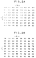
- the quantization matrix factor q depends on only the order (u, v) of the space harmonic and is determined to a fixed value which increases as the order (u, v) of the space harmonic increases, as shown in Figs. 2A and 2B.
- a quantization matrix factor q for a luminance signal (Y) is determined to a relatively small value
- another quantization matrix factor q for a chrominance signal (R-Y, B-Y) of which image quality deterioration is inconspicuous is determined to a relatively large value.
- the dynamic control of the quantization step size Qs is practiced by the dynamic control of the quantization scaling factor f in the produced code amount calculator 5.
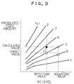
- the quantization scaling factor f is determined to a value which not only decreases at a certain AC level as the target produced code amount increases but also increases at a certain target produced code amount as the AC level of the discrete cosine transform coefficient increases. This is the reason why with the increase of the AC level, the amount of the data to be quantized increases, and the increase of the bit amount of the compressed data after the variable length coding is repressed to smooth the same. As described above, by determining the quantization step size Qs which increases with the increase of the AC level, even when the motion image pattern becomes fine to increase the AC level, the total bit amount of the compressed image data after the variable length coding can be maintained to almost a predetermined value.
- the target produced code amount to be produced for the next one frame is calculated as follows.
- a total number F0 of the frames are supplied to the DCT part 1 at a fixed frame rate, for example, 30 frames/second.
- the required time for the data compression by the hybrid coding that is, the total required time for the recording or reproducing becomes F0/30 seconds.
- a part of the input frames to be recorded is removed at a predetermined thinning rate to exclude from the compression object in the DCT part 1 and thus a frame rate and a bit rate of the compressed image data output from the output terminal OUT are Fr and Br, respectively.
- a total number F1 and a total bit amount Bt of the frames after the data compression by the coding are expressed by the respective following formulas.
- F1 Fr(F0/30) (4)
- Bt Br(F0/30) (5)
- the target produced code amount Bm is obtained by the following formula.
- Bm Bn/F3 (8)
- the calculation of the target produced code amount Bm is performed on the basis of the total bit amount Bc calculated in the produced code amount calculator 5, the frame rate instructed from the external portion, the bit rate and the aforementioned formulas.
- the quantization is executed in the quantization part 3 and then the variable length coding is taken place in the variable length coding part 4.
- the actual produced code amount is shifted from the target value and the variation of the produced code amounts among the frames can be caused.
- the quantization part 3 and the variable length coding part 4 a preceding coding by the preceding step size set part 12, the preceding quantization part 9 and the preceding variable length coding part 10 is carried out.
- the step size is determined by the preceding step size set part 12 on the basis of the detected value obtained in the AC level detector 6 and the calculated value resulted by the target produced code amount calculator 7.
- the code amount actually produced by the preceding coding is calculated in the preceding produced code amount calculator 11, and the calculation result is fed to the step size set part 8.
- the step size determined by the detected value obtained in the AC level detector 6 and the calculation value obtained in the target produced code amount calculator 7, that is, the step size set up in the preceding quantization is corrected on the basis of the error E between the calculation value in the preceding produced code amount calculator 11 and the target produced code amount, and the corrected step size is set up in the quantization part 3.
- This correction method will be described as follows.
- the two systems of the quantization part and the variable length coding part for the final and preceding codings are provided, and the final coding for the present frame and the preceding coding for the following frame are simultaneously processed to enable shortening of the processing time.
- the quantization part, the variable length coding part and the like can be used in common for the final and preceding codings by a time-sharing operation in multiple.
- the produced code amounts among the frames can be smoothed and hence cost reduction of a reproducing part side can be possible.
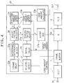
- Fig. 4 there is shown the second embodiment of the motion image data compression coding apparatus according to the present invention, having the same construction as the first embodiment shown in Fig. 1, except that a code amount controller 20 is provided in place of the members 5 to 12 of the first embodiment.
- the code amount controller 20 dynamically controls a variable quantization step size to be set up in a quantization part 3 on the basis of AC components, a target code amount, a produced code amount and so forth so as to keep one frame of code amount produced by a hybrid coding of a combination of a DCT, a quantization and a variable length coding in the vicinity of a target produced code amount to be settled to the same value for all frames.
- a dynamic control of a quantization step size Qs can be realized by a dynamic control of a quantization scaling factor f.
- the code amount controller 20 comprises an AC level detector 21, an interframe difference detector 22a, a one frame delay 22b, a produced code amount calculator 23a, a produced code amount erroe detector 23b, an integration produced code amount error detector 24, an initial value set part 25, an adjusting factor calculator 26, a scaling factor adjustor 27a and a quantization step size set part 27b.
- the AC level detector 21 reads one frame of transform factors out of the frame buffer memory 2 and calculates the sum of the absolute values of all AC components to detect it as the AC component of its frame.
- the interframe difference detector 22a subtracts the present frame of the AC component G(n) directly sent from the AC level detector 21 from the preceding frame of the AC component G(n-1) fed from the AC level detector 21 through the one frame delay 22b to calculate an interframe difference C of the AC component and outputs the obtained interframe difference C to the adjusting factor calculator 26.
- the produced code amount calculator 23a calculates the actually produced code amount (bit sum of the data after the compression coding) B of the frames and outputs the calculation result B to the produced code amount error detector 23b.
- a target code amount M predetermined in advance as its target value is sent to the produced code amount error detector 23b and the initial value set part 25.
- the produced code amount error detector 23b subtracts the target code amount M from the actual produced code amount B fed from the produced code amount calculator 23a to obtain a subtracted value (B-M) and outputs the subtracted value (B-M) as a produced code amount error D to the integration produced code amount error detector 24 and the adjusting factor calculator 26.
- the integration produced code amount error detector 24 integrates the produced code amount error D from the coding start head frame to the preceding frame to obtain an integrated produced code amount error Z to be sent to the adjusting factor calculator 26.
- the adjusting factor calculator 26 receives the interframe difference G, the produced code amount error D and the integrated produced code amount error Z for the interframe difference detector 22a, the produced code amount error detector 23b and the integration produced code amount error detector 24, respectively, and calculates an adjusting factor ⁇ for adjusting the scaling factor predetermined for the preceding frame to obtain a scaling factor for the present frame as follows ⁇ ⁇ D/k1 + Z/k2 + G/k3 (9) wherein k1, k2 and k3 are constants.
- the adjusting factor calculator 26 outputs the obtained adjusting factor ⁇ to the scaling factor adjustor 27a.
- the initial value set part 25 receives the AD level of the transform factor detected for the head frame in the AC level detector 21 and the target code amount M and determines the initial value of the scaling factor f from a table shown in Fig. 5 containing a combination of the received two values to output the initial value of the scaling factor f to the scaling factor adjustor 27a.
- the scaling factor adjustor 27a multiplies the scaling factor f for the preceding frame by (1+ ⁇ ) to obtain a scaling factor f' for the present frame in the following formula f' ⁇ (1+ ⁇ )f (10) and outputs the obtained scaling factor f' to the quantization step size set part 27b.
- the quantization step size set part 27b prepares the quantization step size Qs from the scaling factor f' sent from the scaling factor adjustor 27a and the quantization matrix factors q as exemplified in Figs. 2A and 2B according to formula (3) and outputs the obtained quantization step size Qs to the quantization part 3.
- the quantization is carried out with the quantization step size Qs set up as described above in the scaling factor adjustor 27a.
- the adjusting factor calculator 26 calculates another adjusting factor ⁇ again from the interframe diference G, the produced code amount error D and the integrated produced code amount error Z according to formula (9).
- the scaling factor adjustor 27a obtains another scaling factor from another adjusting factor ⁇ and the and the quantization step size set part 27b produces another quantization step size Qs to carry out the quantization in the quantization part 3 in the same manner as described above.
- Fig. 6 illustrates the result of the compression coding in the motion image data compression coding apparatus shown in Fig. 4.
- the horizontal and vertical axes exhibit the frame number and the calculation value of the actually produced code amount (K bit) for each frame, respectively.
- the Figs. 2A and 2B and Fig. 5 are used for the quantization, and the target produced code amount is determined to 100 kbits.
- the constants k1, k2 and k3 in formula (9) are settled to 10000, 4000 and 5000, respectively.
- the motion data the original video signals which are thinned out to 1/3 of the total frames are used, and as to the AC level, the sum of the absolute values of all AC components is used.
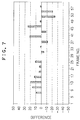
- Fig. 7 shows the variation of the interframe difference G of the AC component with reference to the frame number. Since the original video signals are thinned out to 1/3 of all frames, the adjacent frames to be subjected to the compression coding are aligned at an interval of three times as many as the original frame interval, a fairly large interframe difference G is caused. In spite of the changes of the code amount and the compression efficiency suggested by the occurrence of such a large interframe difference G of the AC component, a good smoothing can be realized, as shown in Fig. 6.
- the motion imatge data compression coding apparatus comprises a block divider 31 connected to an input terminal IN of motion image data to be compressed, a DCT part 32, a quantization (Q) part 33, a variable length coding (VLC) part 34, a data memory 35, a data construction part 36 connected to an output terminal OUT, a quantization step size controller 37 and a code amount controller 38.
- the digital motion image data of the frame structure to be compressed are supplied every frame unit to the block divider 31 through the input terminal IN and are equally divided into blocks having a size of 8 x 8 pixels in the block divider 31 while the divided motion image data are stored every block unit into the data memory 35.
- the DCT part 32 reads the divided motion image data every block unit out of the data memory 35 and carries out a two-dimensional discrete cosine transform of the data to obtain transform coefficient groups.
- the obtained transform coefficient groups are stored in the data memory 35.
- the quantization part 33 reads the transform coefficient groups out of the data memory 35 and quantizes the transform factor groups at a step size based on an instruction output from the quantization step size controller 37.
- the quantized data are stored in the data memory 35.
- the variable length coding part 34 reads the quantized data out of the data memory 35 and carries out the variable length coding where the larger the appearance frequency, the shorter the code is allotted.
- the variable length coded data are stored in the data memory 35.
- the quantization step size controller 37 reads the variable length coded data of the blocks out of the data memory 35 and adds up only the effective data of the variable length coded data except the ineffective data through all blocks within one frame.
- the quantization step size controller 37 also compares one frame of the summed value with a predetermined value.
- the ineffective data mean the data of zero continuing to the end of the block, but the zero data appearing before the effective data are dealt with as the effective data.
- the above-described ineffective data are basically removed when the compressed data are constructed and are exceptionally converted into effective data (ESC code) of a predetermined code length to be included into the compressed data. This conversion from the ineffective data to the effective data will be hereinafter described in detail.
- the quantization step size controller 37 allows the quantization part 33 to increase the desired value of the quantization step size corresponding to the excess amount.
- the quantization step size controller 37 makes the quantization part 33 to reduce a certain value of the quantization step size corresponding to the insufficient amount.
- the absolute value of the quantized data level is small, its appearance frequency is high, when the increase of the quantized step size brings about the reduction of the absolute value of the quantized data, the data amount after the variable length coding is reduced.
- the reduction of the quantized step size makes to increase the absolute value of the quantized data, the data amount after the variable length coding is increased.
- Fig. 9 shows a process for carrying out the code amount control of the variable length coded data read out of the data memory 35 in the code amount controller 38.
- the code amount controller 38 calculates the upper limit code amount F0 of one frame and the upper limit code amount B0 of one block on the basis of an image size, a frame rate and a bit rate input from an external portion via an input part (not shown) and settles the obtained code amounts F0 and B0 in a register included within the code amount controller 38, in advance.
- the code amount controller 38 calculates a code amount B1 of effective data within a head block and compares the calculated code amount B1 with the upper limit code amount B0 of one block in step 101. Depending on the comparison result B1 > B0 or B1 ⁇ B0, the code amount controller 38 discriminates whether the operation is stopped midway (Y) or not (N) in step 102. That is, when B1 > B0, the code amount controller 38 discriminates that it is necessary to stop midway the operation of the effective data when the code amount of the effective data within the block exceeds the upper limit code amount B0 and settles a code BB as the EOB code indicating the end of this block in step 104. Alternately, when B1 ⁇ B0, the code amount controller 38 discriminates that it is unnecessary to stop midway the operation and determines a code AA as the EOB code indicating the end of this block in step 103.
- the code amount controller 38 calculates the number of the ineffective data groups which continue 16 numbers within each block and is convertible into an ESC (escape) code of 12 bit width and stores the calculation result in step 105. That is, it is impossible to convert the ineffective data continuing less than 16 numbers into the ESC code, but the ineffective data group continuing at least 16 through less than 32 numbers can be converted into one ESC code, and the ineffective data group continuing at least 32 through less than 48 numbers can be converted into two ESC codes.
- the code amount controller 38 discriminates whether or not the processing is for the last block within this frame in step 106. When the discrimination result is negative, the operation is returned to step 101 and the same operation described above is repeated to reach the last block within the frame. When the processing of the last block within the frame is finished, the operation is moved to step 107.
- step 107 the code amount controller 38 calculates the sum F1 of the total code amount of the effective data of the total blocks within the frame including the block or blocks the processing of the effective data is stopped midway in step 102, and compares the obtained sum F1 with the upper limit code amount F0 of one frame.
- F1 ⁇ F0 in step 107 the code amount control operation is all finished, and the code amount controller 38 considers all midway stops of the effective data as effective and instructs the construction of the compressed data using the effective data formed with respect to all blocks including the midway stop blocks to the data construction part 36.
- the code amount controller 38 relieves or increases the upper limit code amount B0 of one block for the midway stop blocks in step 108.
- the relief of the upper limit code amount B0 is carried out in the order of the alignment of the midway stop blocks. This relief of the upper limit code amount B0 is repeated until F1 ⁇ F0 in step 107 or it is detected that there becomes no midway stop block by relieving the upper limit code amount B0 in step 109.
- the code amount controller 38 finishes the code amount control operation and instructs the construction of the compressed data using the effective data formed with respect to all blocks including the relieved midway stop blocks to the data construction part 36.
- the code amount controller 38 detects that there is no midway stop block by the relief of the upper limit code amount B0 in step 109, it is discriminated whether F1 ⁇ F0 or not in step 110.
- the code amount controller 38 finishes the code amount control operation and instructs the construction of the compressed data using the effective data formed with respect to all blocks excluding the midway stop blocks to the data construction part 36.
- the code amount controller 38 performs the conversion of the blocks including the convertible continuous ineffective data convertible into the ESC code.
- This conversion into the ESC code is practiced as follows. That is, first, after the conversion into the ESC code of the blocks having the maximum convertible numbers is carried out in the block arrangement order in step 111, the code amount controller 38 discriminates whether or not there is any unconverted block in step 112. When there is the unconverted block or blocks and the code amount controller 38 discriminates that still F1 ⁇ F0 in step 110, the operation is moved again to step 111, and the conversion into the ESC code of the blocks having the large convertible numbers is carried out in the block arrangement order.
- the code amount controller 38 finishes the code amount control operation and instructs the construction of the compressed data to the data construction part 36 in the same manner as described above.
- the code amount controller 38 finishes the code amount control operation and instructs the construction of the compressed data to the data construction part 36 in the same manner as described above.
- the code amount control in the code amount controller 38 has been described in combination with the quantization step size control in the quantization step size controller 37, however, the code amount control by the code amount controller 38 can be carried out independently without combining with the quantization step size control by the quantization step size controller 37 or in combination with another appropriate code amount control method.
- the present invention has been described in connection with the example of the motion image compression of the frame structure, the present invention can be applied to a still image compression of a frame structure.
- the motion image data compression coding of the present invention only or in connection with a variety of data smoothing methods including a conventional quantization step size control or the like, the more effective smoothing of the interframe data can be realized.
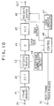
- the motion image data compression coding apparatus comprises a frame memory 41 coupled with an input terminal IN of motion image data to be compressed, a DCT part 42, a first data buffer 43, a quantization (Q) part 44, a variable length coding (VLC) part 45, a second data buffer 46 connected to an output terminal OUT, a produced code amount calculator 47, a controller 48 connected to another output terminal 51 for a next frame transmission requirement, and an interframe correlation detector 49.
- the controller 48 determines a target value (target code amount) of a produced code amount for one frame and the proper value of the minimum quantization step size as an initial value to the quantization part 44. After finishing the initial value setting of the target code amount and a quantization step size, the controller 48 outputs a next frame transmission requirement to a motion image data supply part of a foregoing stage via the output terminal 51. In response to this transmission requirement, one frame of digital pixel data constituting motion image data to be compressed are transmitted to the frame memory 41 through the input terminal IN and are stored in the frame memory 41.
- the obtained transform coefficient group is stored in the first data buffer 43.
- the quantization part 44 reads the transform factor group out of the first data buffer 43 and quantizes the transform factor group based on the quantization step size instructed by the controller 48, and the quantized data are sent to the variable length coding part 45.
- variable length coding part 45 carries out a variable length coding of the quantized data, that is, allots a shorter code to the quantized data as its appearance frequency is smaller.
- the obtained variable length coded data are sent to the second data buffer 46 and the produced code amount calculator 47 and are stored in the second data buffer 46.
- the produced code amount calculator 47 adds up one frame of code amount of the variable length coded data to be written in the second data buffer 46 and outputs the summed up value as the produced code amount to the controller 48.
- the controller 48 compares the produced code amount sent from the produced code amount calculator 47 with a predetermined target code amount. Since the initial value of the quantization step size is set to the minimum value, at the stage that the first quantization and variable length coding are finished, the produced code amount can exceed the target code amount with a sufficient large probability.
- the controller 48 increases the quantization step size to be set in the quantization part 44 by a predetermined step and instructs the reprocessing of the quantization and the variable length coding to the quantization part 44 and the variable length coding part 45, respectively.
- the shorter code is allotted as the level is lower in the variable length coding.
- the controller 48 compares the produced code amount obtained over again with the target code amount, and, when the produced code amount still exceeds the target code amount, after further increasing the quantization step size by the predetermined step, the controller 48 instructs the reprocessing of the quantization and the variable length coding to the quantization part 44 and the variable length coding part 45, respectively.
- the controller 48 instructs to allow the second data buffer 46 to output the stored data to the output terminal OUT.
- the controller 48 also determines the initial value of the above-described quantization step size to the quantization part 44 and outputs the next frame transmission requirement to the output terminal 51 in order to start the processing of the next frame.
- the compression coding processing of the next frame is carried out in the same manner as described above.
- Fig. 11 shows the above-described motion image data compression coding process, and steps 201 to 211 indicate the aforementioned basic processing contents.
- the interframe correlation detector 49 detects the difference between the sums of the absolute values of the AC components of the discrete cosine transform coefficient of the present frame to be compression-coded and the preceding frame compression-coded, and compares the obtained difference with a predetermined value so as to detect whether or not there is correlation between the two frames concerning the pattern. The detected result is sent to the controller 48.
- the controller 48 sets up the last value of the quantized step size obtained for the preceding frame or a one through two step smaller value than the last value as the initial value of the quantization step size.
- the interframe correlation detector 49 detects that there is no correlation, for example, due to a large change of the pattern by a scene switching, the interframe correlation detector 49 sets up the initial value of the quantization step size to the above-described minimum vaule in preparation for a large change of the produced code amount from the preceding frame.
- the interframe correlation detector 49 is supplemented in order to shorten the processing time, however, when it is not so much necessary to reduce the processing time, the interframe correlation detector 49 can be omitted.
Abstract
Description
- The present invention relates to a motion image data compression coding apparatus for compressing a data amount by successively carrying out an orthogonal transform, a quantization and a variable length coding of motion image data of one frame and an image data compression coding method for use in the motion image recording and reproducing system.
- Now, a recording and reproducing system is being developed, and in this system, a frame structure of motion image data for games, educations or the like are coded for compressing the data amount, and the coded data are recorded onto or reproduced out of a large capacity recording medium such as a CD-ROM or the like.
- Conventionally, as a high performance one of various coding systems for data compression, a hybrid coding system is known, and in this system, equal division of one frame of image data into blocks, an orthogonal transform such as discrete cosine transform (DCT) or the like, a quantization and a variable length coding (VLC) are applied. The detail of this hybrid coding system is disclosed in Japanese Patent Applications No. 87-313850 "DCT-VQ compressed motion image data transmission system" and No. 90-184242 "DCT compressed motion image data recording and reproducing system".
- In this conventional hybrid coding system, with a change of the data amount and the compression efficient depending upon the image conditions, the data amount (produced code amount) after compression is also changed every frame. Hence, on reproducing, a relatively large capacity of buffer circuit and a complex control system for the buffering are required.
- In the coding, as described above, in order to reduce the buffer memory size and simplify the synchronization control in the reproducing part, it is desirable to make smooth one frame of compressed data as flat as possible, and in order to realize this, a variety of methods have been proposed, for example, one frame of entire code amount is calculated, and to the direction to keep this, the step size of the quantization is dynamically varied.
- However, even in such conventional various data smoothing methods including the dynamic change of the quantization step size, it is still insufficient in respect of the data smoothing, and a more effective smoothing method is demanded.
- It is therefore an object of the present invention to provide a motion image data compression coding apparatus in view of the problems of the prior art, which is capable of smoothing a produced code amount among frames and compressed data among the frames.
- It is another object of the present invention to provide an image data compression coding method in view of the problems of the prior art, which is capable of smoothing a produced code amount among frames and compressed data among the frames.
- In accordance with one aspect of the present invention, there is provided a motion image data compression coding apparatus, comprising orthogonal transform means for carrying out an orthogonal transform of motion image data of a frame structure to obtain transform coefficients; quantization means for quantizing the transform coefficients sent from the orthogonal transform means through a buffer memory with a variable quantization step size to obtain quantized data; variable length coding means for carrying out a variable length coding of the quantized data to output compressed coded data to an output terminal; code amount calculator means for calculating a code amount of the compressed coded data produced every frame; preceding quantization means for quantizing the transform coefficients of one frame read out of the buffer memory with a second variable quantization step size to obtain second quantized data prior to the quantization of the quantization means and the variable length coding of the variable length coding means; preceding variable length coding means for carrying out a second variable length coding of the second quantized data to output second compressed coded data; preceding code amount calculator means for calculating a second code amount of the second compressed coded data produced every frame; AC level detector means for detecting an AC level reflecting an amplitude size of AC components of the transform factors every one frame; target code amount calculator means for calculating a target code amount as a target value of a code amount of a next frame on the basis of the code amount calculated by the code amount calculator means and an instruction input from an external part; preceding step size set means for calculating a scaling factor from the calculated value of the target code amount calculator means and the detected value of the AC level detector means, calculating a second quantization step size from a product of the scaling factor and quantization matrix factors set for the AC components of the transform factors and setting the second quantization step size to the preceding quantization means; and step size set means for calculating a quantization step size from the calculated value of the target code amount calculator means, the detected value of the AC level detector means and the calculated value of the preceding code amount calculator means and setting the quantization step size to the quantization means.
- The AC level detector means can detect a sum of absolute values of levels of the AC components of the transform coefficients as the AC level.
- In accordance with another aspect of the present invention, there is provided a motion image data compression coding apparatus for compressing a data amount by successively carrying out an orthogonal transform, a quantization and a variable length coding of motion image data of one frame structure, comprising AC level detector means for detecting an AC level reflecting an amplitude size of AC components of transform coefficients produced by the orthogonal transform every one frame; interframe difference detector means for detecting an interframe difference G of the AC level between a preceding frame and a present frame, detected by the AC level detector means; code amount error detector means for detecting a code amount error difference D between a code amount of compressed coded data produced every frame by the variable length coding and a target code amount as a target value of the code amount; addition code amount error detector means for adding up the code amount error differences D from a head frame through the present frame to detect an addition code amount error Z; initial value set means for setting an initial value of a scaling factor f relating to a quantization step size from a combination of the AC level of the detected transform coefficients of the head frame and the target code amount; scaling factor adjusting means for adjusting the scaling factor f set for the preceding frame on the basis of the code amount error D, the code amount error Z and the interframe difference G; and calculator means for calculating the quantization step size in the quantizing from a product of the scaling factor f adjusted by the scaling factor adjusting means and quantization matrix factors q set for the AC components of the transform coefficients
The scaling factor adjusting means can include an adjusting factor calculator means for calculating an adjusting factor α for adjusting a scaling factor set for the present frame by multiplying the scaling factor f for the preceding frame by (1 + α) according to the following formula

wherein k1, k2 and k3 are constants. - In accordance with a further aspect of the present invention, there is provided an image data compression coding method for use in an image data compression coding apparatus for compressing a data amount by a hybrid coding of a combination of a block dividing within a frame, a discrete cosine transform within the block, a quantization and a variable length coding of image data of one frame structure, comprising the steps of a first stage for setting an upper limit code amount F0 of one frame and an upper limit code amount B0 of one block according to an instruction input from an external part; a second stage for calculating a code amount B1 of effective data except ineffective data including zero data continuing up to a block end by the hybrid coding of the blocks within one frame, and carrying out a midway stop of the effective data for an excess part of each block in which the code amount B1 exceeds the upper limit code amount B0; and a third stage for adding up all code amounts of the effective data of all blocks within the frame including the midway stop blocks after coding to obtain a total code amount F1 of one frame, comparing the total code amount F1 with an upper limit code amount F0, and either when F1 ≧ F0, carrying out a construction of compressed data by using the formed effective data of all blocks including the midway stop blocks, or when F1 < F0, while the upper limit code amount B0 for the midway stop blocks is increased until either F1 becomes at least F0 or there becomes no midway stop block by the increase of the upper limit code amount B0, carrying out the construction of the compressed data by using the effective data including the increased parts.
- The second stage can further include calculating a number of ineffective data groups convertible into effective data (ESC code) of a predetermined code length, the ineffective data groups appearing in the form of a predetermined number of continuing ineffective data within each block, and the third stage can further include, when the construction of the compressed data of the one frame is finished before the total code amount F1 reach the upper limit code amount F0, converting the ineffective data groups of the block into the effective data (ESC code) until either F1 becomes at least F0 or the construction of the compressed data of the block is finished.
- In accordance with still another aspect of the present invention, there is provided a motion image data compression coding apparatus, comprising discrete cosine transform means for, while each frame of image data of one frame structure is equally divided into a plurality of blocks, carrying out a discrete cosine transform of pixel data within each block to obtain transform coefficients; quantization means for quantizing the transform coefficients to obtain quantized data; variable length coding means for carrying out a variable length coding of the quantized data to obtain compressed coded data; code amount calculator means for calculating a code amount of the compressed coded data within the frame; and controller means for setting a target code amount of a target value of the code amount and a proper minimum quantization step size for the quantization as initial values, and, while gradually increasing the quantization step size with a predetermined step, repeating the quantization in the quantization means and the variable length coding in the variable length coding means until the code amount becomes at most the target code amount.
- The apparatus can further comprises interframe difference detector means for detecting an interframe difference of correlation of a pattern between preceding and present frames, and when the detected interframe difference is smaller than a predetermined value, the controller means sets either a last quantization step size obtained for the preceding frame or a predetermined step smaller quantization step size than the last quantization step size as the initial value in place of the minimum step size.
- The objects, features and advantages of the present invention will become more apparent from the consideration of the following detailed description, taken in conjunction with the accompanying drawings, in which:
- Fig. 1 is a block diagram of a motion image data compression coding apparatus according to a first embodiment of the present invention;
- Figs. 2A and 2B show quantization matrix factors for luminace and chrominance signals, respectively, to be used for quantization in the apparatus shown in Fig. 1;
- Fig. 3 is a graphical representation of characteristics to be used for determining a scaling factor from an AC level of one frame and a target produced code amount in the apparatus shown in Fig. 1;
- Fig. 4 is a block diagram of a motion image data compression coding apparatus according to a second embodiment of the present invention;
- Fig. 5 is shows a prediction table for determining an initial value of a scaling factor f from an AC level of the head frame and a target produced code amount in the apparatus shown in Fig. 4;
- Fig. 6 is a graphical representation showing a result of a compressed produced coding in the apparatus shown in Fig. 4;
- Fig. 7 is a graphical representation showing a variation result of an interframe difference G of an AC component corresponding to the result shown in Fig. 6;
- Fig. 8 is a block diagram of a motion image data compression coding apparatus according to a third embodiment of the present invention;
- Fig. 9 is a flow chart of a code amount smoothing process in a code amount controller shown in Fig. 8;
- Fig. 10 is a block diagram of a motion image data compression coding apparatus according to a fourth embodiment of the present invention; and
- Fig. 11 is a flow chart of a compression coding process carried out in the apparatus shown in Fig. 10.
- Referring now to the drawings, wherein like reference characters designate like or corresponding parts throughout the views and thus the repeated description thereof call be omitted for brevity, there is shown in Fig. 1 the first embodiment of a motion image data compression coding apparatus according to the present invention.
- As shown in Fig. 1, the motion image data compression coding apparatus comprises a DCT (discrete cosine transform)
part 1 coupled to an input terminal IN of motion image data to be compressed, aframe buffer memory 2, a quantization (Q)part 3 of a variable step size, a variable length coding (VLC)part 4 connected to an output terminal OUT, a producedcode amount calculator 5, anAC level detector 6, a target producedcode amount calculator 7, a step size setpart 8, a precedingquantization part 9, a preceding variablelength coding part 10, a preceding producedcode amount calculator 11 and a preceding step size setpart 12. - In this embodiment, in the
DCT part 1, the motion image data of the frame structure supplied from the input terminal IN are divided into a plurality of blocks every one frame unit and a discrete cosine transform is carried out every block to obtain transform efficient groups including AC and DC components. This discrete cosine transform is carried out in a conventional manner, as disclosed in the aforementioned Japanese Patent applications No. 87-313850 and No. 90-184242. The transform coefficients output from theDCT part 1 are sent to thequantization part 3 through theframe buffer memory 2 and are quantized with a variable step size dynamically changed according to the produced code amount and the like. As to this quantization method, not a vector quantization method as disclosed in Japanese Patent application No. 87-313850 but a usual scalar quantization method as disclosed in Japanese Patent application No. 90-184242 call be used. The quantized data output from thequantization part 3 is converted into variable length codes in the variablelength coding part 4, and the obtained variable length codes are output to the producedcode amount calculator 5 and a recording device such as a CD-ROM via the output terminal OUT. - In the produced
code amount calculator 5, one frame of code amount produced by a hybrid coding of a combination of the aforementioned discrete cosine transform, the quantization of the variable step size and the variable length coding is summed with the code amount up to the present frame to calculate the produced code amount, and the calculation result is sent to the target producedcode amount calculator 7. In the target producedcode amount calculator 7, a target produced code amount to be produced for the following one frame is calculated from the calculation result in the producedcode amount calculator 5 and an instruction given from an external part and is output to the step size setpart 8 and the preceding step size setpart 12. - In the
AC level detector 6, one frame of the discrete cosine transform coefficients k(u, v) read out of theframe buffer memory 2 are input prior to the preceding quantization in the precedingquantization part 9, and a sum P of absolute values of all AC components except DC components is calculated to detect it as an AC level of its frame according to the following formula.

The detected AC level is fed to the step size setpart 8 and the preceding step size setpart 12. - In the
quantization part 3, with the variable quantization step size determined by the step size setpart 8, the transform coefficient read out of theframe buffer memory 2 is quantized. Now, assuming that the input to thequantization part 3 is A and the quantization step size is Qs, the output A' from thequantization part 3 is represented by the following formula.

- In the quantization of the discrete cosine transform coefficients, as the quantization step size Qs is enlarged, the code amount (bit sum) of the compressed data after the variable length coding is reduced and the data compression rate is raised. This is the reason why the more the level of the quantization step size Qs is increased, the lower the output A' of the
quantization part 3 and why the lower the level of the output A' of low appearance frequency in the following variablelength coding part 4, the shorter the bit number of the code allotted. As described above, as the quantization step size Qs is enlarged, the data compression rate is increased, and on the contrary, as the quantization noise increases, the image quality of the reproduced image is fallen. Hence, although it is necessary to determine the quantization step in consideration of the data compression rate and the image quality deteioration allowance, the control and smoothing of the produced code amount are further considered in the compression coding system according to the present invention. - Relating to the motion image data, from the physiological characteristics of a viewer, it is known that the higher the space frequency of the AC component, the lower the image quality deterioration by the quantization noise can be allowed. In this embodiment, the quantization step size Qs is determined by attention to the above-described visual characteristics so as to be a large value as the space frequency of the AC component becomes higher. Hence, the quantization step size Qs is disintegrated into a quantization matrix factor q which depends on an order of a space harmonic and a quantization scaling factor f, as represented by the following formula

wherein k is constant. - First, the quantization matrix factor q depends on only the order (u, v) of the space harmonic and is determined to a fixed value which increases as the order (u, v) of the space harmonic increases, as shown in Figs. 2A and 2B. For example, as shown in Fig. 2A, a quantization matrix factor q for a luminance signal (Y) is determined to a relatively small value, and as shown in Fig. 2B, another quantization matrix factor q for a chrominance signal (R-Y, B-Y) of which image quality deterioration is inconspicuous is determined to a relatively large value. The dynamic control of the quantization step size Qs is practiced by the dynamic control of the quantization scaling factor f in the produced
code amount calculator 5. - Next, as shown in Fig. 3, the quantization scaling factor f is determined to a value which not only decreases at a certain AC level as the target produced code amount increases but also increases at a certain target produced code amount as the AC level of the discrete cosine transform coefficient increases. This is the reason why with the increase of the AC level, the amount of the data to be quantized increases, and the increase of the bit amount of the compressed data after the variable length coding is repressed to smooth the same. As described above, by determining the quantization step size Qs which increases with the increase of the AC level, even when the motion image pattern becomes fine to increase the AC level, the total bit amount of the compressed image data after the variable length coding can be maintained to almost a predetermined value.
- In the target produced
code amount calculator 7, on the basis of the calculation result of the producedcode amount calculator 5 and the instruction fed from the external portion, the target produced code amount to be produced for the next one frame is calculated as follows. - From the input terminal IN, a total number F0 of the frames are supplied to the
DCT part 1 at a fixed frame rate, for example, 30 frames/second. The required time for the data compression by the hybrid coding, that is, the total required time for the recording or reproducing becomes F0/30 seconds. Further, it is considered that a part of the input frames to be recorded is removed at a predetermined thinning rate to exclude from the compression object in theDCT part 1 and thus a frame rate and a bit rate of the compressed image data output from the output terminal OUT are Fr and Br, respectively. Hence, a total number F1 and a total bit amount Bt of the frames after the data compression by the coding are expressed by the respective following formulas.


- At the same time of the coding start for the data, the calculations of the total number F1 of the coded frames and the total bit amount Bt produced by the coding are started, and it is considered that these two reach F2 and Bc, respectively, at the point the compression of a certain frame is finished, a remaining frame number F3 and a remaining produced allowable bit amount Bn of the compression object are obtained by the following formulas.


- When an allowable value of the bit amount produced by the compression of the next one frame is defined as a target produced code amount Bm, the target produced code amount Bm is obtained by the following formula.

The calculation of the target produced code amount Bm is performed on the basis of the total bit amount Bc calculated in the producedcode amount calculator 5, the frame rate instructed from the external portion, the bit rate and the aforementioned formulas. - As described above, with the quantization step size Qs set up by the step size set
part 8, the quantization is executed in thequantization part 3 and then the variable length coding is taken place in the variablelength coding part 4. However, due to the incompleteness of the characteristics shown in Fig. 3 and the like, the actual produced code amount is shifted from the target value and the variation of the produced code amounts among the frames can be caused. - In this embodiment, in order to avoid the produced code amount variation among the frames, prior to the final coding by the step size set
part 8, thequantization part 3 and the variablelength coding part 4, a preceding coding by the preceding step size setpart 12, the precedingquantization part 9 and the preceding variablelength coding part 10 is carried out. In this preceding coding, the step size is determined by the preceding step size setpart 12 on the basis of the detected value obtained in theAC level detector 6 and the calculated value resulted by the target producedcode amount calculator 7. The code amount actually produced by the preceding coding is calculated in the preceding producedcode amount calculator 11, and the calculation result is fed to the step size setpart 8. - In the step size set
part 8, the step size determined by the detected value obtained in theAC level detector 6 and the calculation value obtained in the target producedcode amount calculator 7, that is, the step size set up in the preceding quantization is corrected on the basis of the error E between the calculation value in the preceding producedcode amount calculator 11 and the target produced code amount, and the corrected step size is set up in thequantization part 3. One example of this correction method will be described as follows. - That is, as exemplified in Fig. 3, from an intersect (a white circle mark in Fig. 3) between a detected value of an AC level and a target produced code amount, 5 as a scaling factor f is settled, and then a preceding quantization and a preceding variable length coding are carried out by the preceding
quantization part 9 and the preceding variablelength coding part 10, respectively, to obtain an error E (as shown by a dark circle mark) of which the calculation value in the preceding producedcode amount calculator 11 exceeds the target value. Such an error occurrence is deemed to be attributed to the weakness of the relationship between the AC level and the scaling factor f, and the detected value of the AC level is adjusted to a value (adjusting value) imparting an intersect (a triangular mark) between a characteristic curve of scalingfactor 5 and the calculated value. Accordingly, scalingfactor 6 nearest to an intersect (a rectangular mark) between the adjusting value and the target produced code amount is determined on the final quantization. - In this embodiment, as described above, the two systems of the quantization part and the variable length coding part for the final and preceding codings, are provided, and the final coding for the present frame and the preceding coding for the following frame are simultaneously processed to enable shortening of the processing time. However, in case that a hardware scale reduction is preferential to the processing time reduction, the quantization part, the variable length coding part and the like can be used in common for the final and preceding codings by a time-sharing operation in multiple.
- In this embodiment, as described above, the produced code amounts among the frames can be smoothed and hence cost reduction of a reproducing part side can be possible.
- In Fig. 4, there is shown the second embodiment of the motion image data compression coding apparatus according to the present invention, having the same construction as the first embodiment shown in Fig. 1, except that a
code amount controller 20 is provided in place of themembers 5 to 12 of the first embodiment. - In this embodiment, the
code amount controller 20 dynamically controls a variable quantization step size to be set up in aquantization part 3 on the basis of AC components, a target code amount, a produced code amount and so forth so as to keep one frame of code amount produced by a hybrid coding of a combination of a DCT, a quantization and a variable length coding in the vicinity of a target produced code amount to be settled to the same value for all frames. In thecode amount controller 20, a dynamic control of a quantization step size Qs can be realized by a dynamic control of a quantization scaling factor f. - The
code amount controller 20 comprises anAC level detector 21, aninterframe difference detector 22a, a oneframe delay 22b, a producedcode amount calculator 23a, a produced codeamount erroe detector 23b, an integration produced codeamount error detector 24, an initial value setpart 25, an adjustingfactor calculator 26, a scalingfactor adjustor 27a and a quantization step size setpart 27b. - The
AC level detector 21 reads one frame of transform factors out of theframe buffer memory 2 and calculates the sum of the absolute values of all AC components to detect it as the AC component of its frame. Theinterframe difference detector 22a subtracts the present frame of the AC component G(n) directly sent from theAC level detector 21 from the preceding frame of the AC component G(n-1) fed from theAC level detector 21 through the oneframe delay 22b to calculate an interframe difference C of the AC component and outputs the obtained interframe difference C to the adjustingfactor calculator 26. The producedcode amount calculator 23a calculates the actually produced code amount (bit sum of the data after the compression coding) B of the frames and outputs the calculation result B to the produced codeamount error detector 23b. A target code amount M predetermined in advance as its target value is sent to the produced codeamount error detector 23b and the initial value setpart 25. The produced codeamount error detector 23b subtracts the target code amount M from the actual produced code amount B fed from the producedcode amount calculator 23a to obtain a subtracted value (B-M) and outputs the subtracted value (B-M) as a produced code amount error D to the integration produced codeamount error detector 24 and the adjustingfactor calculator 26. The integration produced codeamount error detector 24 integrates the produced code amount error D from the coding start head frame to the preceding frame to obtain an integrated produced code amount error Z to be sent to the adjustingfactor calculator 26. - The adjusting
factor calculator 26 receives the interframe difference G, the produced code amount error D and the integrated produced code amount error Z for theinterframe difference detector 22a, the produced codeamount error detector 23b and the integration produced codeamount error detector 24, respectively, and calculates an adjusting factor α for adjusting the scaling factor predetermined for the preceding frame to obtain a scaling factor for the present frame as follows

wherein k1, k2 and k3 are constants. The adjustingfactor calculator 26 outputs the obtained adjusting factor α to thescaling factor adjustor 27a. - On the other hand, the initial value set
part 25 receives the AD level of the transform factor detected for the head frame in theAC level detector 21 and the target code amount M and determines the initial value of the scaling factor f from a table shown in Fig. 5 containing a combination of the received two values to output the initial value of the scaling factor f to thescaling factor adjustor 27a. - The scaling
factor adjustor 27a multiplies the scaling factor f for the preceding frame by (1+ α) to obtain a scaling factor f' for the present frame in the following formula

and outputs the obtained scaling factor f' to the quantization step size setpart 27b. - The quantization step size set
part 27b prepares the quantization step size Qs from the scaling factor f' sent from the scalingfactor adjustor 27a and the quantization matrix factors q as exemplified in Figs. 2A and 2B according to formula (3) and outputs the obtained quantization step size Qs to thequantization part 3. - Then, in the
quantization part 3, in respect of the head frame to be compression-coded, the quantization is carried out with the quantization step size Qs set up as described above in thescaling factor adjustor 27a. For the following frames to the head frame, the adjustingfactor calculator 26 calculates another adjusting factor α again from the interframe diference G, the produced code amount error D and the integrated produced code amount error Z according to formula (9). The scalingfactor adjustor 27a obtains another scaling factor from another adjusting factor α and the and the quantization step size setpart 27b produces another quantization step size Qs to carry out the quantization in thequantization part 3 in the same manner as described above. - Fig. 6 illustrates the result of the compression coding in the motion image data compression coding apparatus shown in Fig. 4. In Fig. 6, the horizontal and vertical axes exhibit the frame number and the calculation value of the actually produced code amount (K bit) for each frame, respectively. In this embodiment, the Figs. 2A and 2B and Fig. 5 are used for the quantization, and the target produced code amount is determined to 100 kbits. The constants k1, k2 and k3 in formula (9) are settled to 10000, 4000 and 5000, respectively. Further, as the motion data, the original video signals which are thinned out to 1/3 of the total frames are used, and as to the AC level, the sum of the absolute values of all AC components is used.
- Fig. 7 shows the variation of the interframe difference G of the AC component with reference to the frame number. Since the original video signals are thinned out to 1/3 of all frames, the adjacent frames to be subjected to the compression coding are aligned at an interval of three times as many as the original frame interval, a fairly large interframe difference G is caused. In spite of the changes of the code amount and the compression efficiency suggested by the occurrence of such a large interframe difference G of the AC component, a good smoothing can be realized, as shown in Fig. 6.
- In Fig. 8, there is shown the third embodiment of the motion image data compression coding apparatus according to the present invention. In this embodiment, the motion imatge data compression coding apparatus comprises a
block divider 31 connected to an input terminal IN of motion image data to be compressed, aDCT part 32, a quantization (Q)part 33, a variable length coding (VLC)part 34, adata memory 35, adata construction part 36 connected to an output terminal OUT, a quantizationstep size controller 37 and acode amount controller 38. - In this embodiment, the digital motion image data of the frame structure to be compressed are supplied every frame unit to the
block divider 31 through the input terminal IN and are equally divided into blocks having a size of 8 x 8 pixels in theblock divider 31 while the divided motion image data are stored every block unit into thedata memory 35. TheDCT part 32 reads the divided motion image data every block unit out of thedata memory 35 and carries out a two-dimensional discrete cosine transform of the data to obtain transform coefficient groups. The obtained transform coefficient groups are stored in thedata memory 35. Thequantization part 33 reads the transform coefficient groups out of thedata memory 35 and quantizes the transform factor groups at a step size based on an instruction output from the quantizationstep size controller 37. The quantized data are stored in thedata memory 35. The variablelength coding part 34 reads the quantized data out of thedata memory 35 and carries out the variable length coding where the larger the appearance frequency, the shorter the code is allotted. The variable length coded data are stored in thedata memory 35. - The quantization
step size controller 37 reads the variable length coded data of the blocks out of thedata memory 35 and adds up only the effective data of the variable length coded data except the ineffective data through all blocks within one frame. The quantizationstep size controller 37 also compares one frame of the summed value with a predetermined value. In this embodiment, the ineffective data mean the data of zero continuing to the end of the block, but the zero data appearing before the effective data are dealt with as the effective data. The above-described ineffective data are basically removed when the compressed data are constructed and are exceptionally converted into effective data (ESC code) of a predetermined code length to be included into the compressed data. This conversion from the ineffective data to the effective data will be hereinafter described in detail. - When the sum value of the above-described one frame of the effective data is over the predetermined value, the quantization
step size controller 37 allows thequantization part 33 to increase the desired value of the quantization step size corresponding to the excess amount. On the contrary, when the sum value of the one frame of the effective data is under the predetermined value, the quantizationstep size controller 37 makes thequantization part 33 to reduce a certain value of the quantization step size corresponding to the insufficient amount. Generally, since, as the absolute value of the quantized data level is small, its appearance frequency is high, when the increase of the quantized step size brings about the reduction of the absolute value of the quantized data, the data amount after the variable length coding is reduced. In turn, when the reduction of the quantized step size makes to increase the absolute value of the quantized data, the data amount after the variable length coding is increased. - Fig. 9 shows a process for carrying out the code amount control of the variable length coded data read out of the
data memory 35 in thecode amount controller 38. Prior to the processing of each frame, thecode amount controller 38 calculates the upper limit code amount F0 of one frame and the upper limit code amount B0 of one block on the basis of an image size, a frame rate and a bit rate input from an external portion via an input part (not shown) and settles the obtained code amounts F0 and B0 in a register included within thecode amount controller 38, in advance. - When the code amount control operation is started, first, the
code amount controller 38 calculates a code amount B1 of effective data within a head block and compares the calculated code amount B1 with the upper limit code amount B0 of one block instep 101. Depending on the comparison result B1 > B0 or B1 ≦ B0, thecode amount controller 38 discriminates whether the operation is stopped midway (Y) or not (N) instep 102. That is, when B1 > B0, thecode amount controller 38 discriminates that it is necessary to stop midway the operation of the effective data when the code amount of the effective data within the block exceeds the upper limit code amount B0 and settles a code BB as the EOB code indicating the end of this block instep 104. Alternately, when B1 ≦ B0, thecode amount controller 38 discriminates that it is unnecessary to stop midway the operation and determines a code AA as the EOB code indicating the end of this block instep 103. - Next, the
code amount controller 38 calculates the number of the ineffective data groups which continue 16 numbers within each block and is convertible into an ESC (escape) code of 12 bit width and stores the calculation result instep 105. That is, it is impossible to convert the ineffective data continuing less than 16 numbers into the ESC code, but the ineffective data group continuing at least 16 through less than 32 numbers can be converted into one ESC code, and the ineffective data group continuing at least 32 through less than 48 numbers can be converted into two ESC codes. When the number of the data within one block is 64, the convertible number to the ESC code is any of "0", "1", " 2" and "3". After the processing of the head block is finished, thecode amount controller 38 discriminates whether or not the processing is for the last block within this frame instep 106. When the discrimination result is negative, the operation is returned to step 101 and the same operation described above is repeated to reach the last block within the frame. When the processing of the last block within the frame is finished, the operation is moved to step 107. - In
step 107, thecode amount controller 38 calculates the sum F1 of the total code amount of the effective data of the total blocks within the frame including the block or blocks the processing of the effective data is stopped midway instep 102, and compares the obtained sum F1 with the upper limit code amount F0 of one frame. When F1 ≧ F0 instep 107, the code amount control operation is all finished, and thecode amount controller 38 considers all midway stops of the effective data as effective and instructs the construction of the compressed data using the effective data formed with respect to all blocks including the midway stop blocks to thedata construction part 36. When F1 < F0 instep 107, thecode amount controller 38 relieves or increases the upper limit code amount B0 of one block for the midway stop blocks instep 108. The relief of the upper limit code amount B0 is carried out in the order of the alignment of the midway stop blocks. This relief of the upper limit code amount B0 is repeated until F1 ≧ F0 instep 107 or it is detected that there becomes no midway stop block by relieving the upper limit code amount B0 instep 109. - When F1 ≧ F0 with the relief of the upper limit code amount B0 in
step 107, thecode amount controller 38 finishes the code amount control operation and instructs the construction of the compressed data using the effective data formed with respect to all blocks including the relieved midway stop blocks to thedata construction part 36. When thecode amount controller 38 detects that there is no midway stop block by the relief of the upper limit code amount B0 instep 109, it is discriminated whether F1 ≧ F0 or not instep 110. When F1 ≧ F0 instep 110, thecode amount controller 38 finishes the code amount control operation and instructs the construction of the compressed data using the effective data formed with respect to all blocks excluding the midway stop blocks to thedata construction part 36. - When F1 < F0 in
step 110, thecode amount controller 38 performs the conversion of the blocks including the convertible continuous ineffective data convertible into the ESC code. This conversion into the ESC code is practiced as follows. That is, first, after the conversion into the ESC code of the blocks having the maximum convertible numbers is carried out in the block arrangement order instep 111, thecode amount controller 38 discriminates whether or not there is any unconverted block instep 112. When there is the unconverted block or blocks and thecode amount controller 38 discriminates that still F1 < F0 instep 110, the operation is moved again to step 111, and the conversion into the ESC code of the blocks having the large convertible numbers is carried out in the block arrangement order. The above-described operation is repeated, and every time the conversion into the ESC code is executed, the code amount F1 of the effective data within the frame is increased by a predetermined value, for example, 12 bits in this embodiment. When it is discriminated that F1 ≧ F0 in the course of the conversion into the ESC code instep 110, thecode amount controller 38 finishes the code amount control operation and instructs the construction of the compressed data to thedata construction part 36 in the same manner as described above. - When the conversion into the ESC code for all the blocks is finished and there is no unconverted block in
step 112, thecode amount controller 38 finishes the code amount control operation and instructs the construction of the compressed data to thedata construction part 36 in the same manner as described above. - As described above, according to the present invention, although the code amount control in the
code amount controller 38 has been described in combination with the quantization step size control in the quantizationstep size controller 37, however, the code amount control by thecode amount controller 38 can be carried out independently without combining with the quantization step size control by the quantizationstep size controller 37 or in combination with another appropriate code amount control method. - In this embodiment, although the present invention has been described in connection with the example of the motion image compression of the frame structure, the present invention can be applied to a still image compression of a frame structure.
- In this embodiment, as described above, by the motion image data compression coding of the present invention only or in connection with a variety of data smoothing methods including a conventional quantization step size control or the like, the more effective smoothing of the interframe data can be realized.
- In Fig. 10, there is shown the fourth embodiment of the motion image data compression coding apparatus according to the present invention. In this embodiment, the motion image data compression coding apparatus comprises a
frame memory 41 coupled with an input terminal IN of motion image data to be compressed, aDCT part 42, afirst data buffer 43, a quantization (Q)part 44, a variable length coding (VLC)part 45, asecond data buffer 46 connected to an output terminal OUT, a producedcode amount calculator 47, acontroller 48 connected to anotheroutput terminal 51 for a next frame transmission requirement, and aninterframe correlation detector 49. - In this embodiment, the
controller 48 determines a target value (target code amount) of a produced code amount for one frame and the proper value of the minimum quantization step size as an initial value to thequantization part 44. After finishing the initial value setting of the target code amount and a quantization step size, thecontroller 48 outputs a next frame transmission requirement to a motion image data supply part of a foregoing stage via theoutput terminal 51. In response to this transmission requirement, one frame of digital pixel data constituting motion image data to be compressed are transmitted to theframe memory 41 through the input terminal IN and are stored in theframe memory 41. - The
DCT part 42 reads one frame of pixel data out of theframe memory 41 while the one frame of pixel data are equally divided into a proper number of blocks, for example, 8 x 8 = 64 blocks, and performs a two-dimensional discrete cosine transform of the pixel data contained within each block to obtain a transform coefficient group. The obtained transform coefficient group is stored in thefirst data buffer 43. Thequantization part 44 reads the transform factor group out of thefirst data buffer 43 and quantizes the transform factor group based on the quantization step size instructed by thecontroller 48, and the quantized data are sent to the variablelength coding part 45. The variablelength coding part 45 carries out a variable length coding of the quantized data, that is, allots a shorter code to the quantized data as its appearance frequency is smaller. The obtained variable length coded data are sent to thesecond data buffer 46 and the producedcode amount calculator 47 and are stored in thesecond data buffer 46. - The produced
code amount calculator 47 adds up one frame of code amount of the variable length coded data to be written in thesecond data buffer 46 and outputs the summed up value as the produced code amount to thecontroller 48. Thecontroller 48 compares the produced code amount sent from the producedcode amount calculator 47 with a predetermined target code amount. Since the initial value of the quantization step size is set to the minimum value, at the stage that the first quantization and variable length coding are finished, the produced code amount can exceed the target code amount with a sufficient large probability. - The
controller 48 increases the quantization step size to be set in thequantization part 44 by a predetermined step and instructs the reprocessing of the quantization and the variable length coding to thequantization part 44 and the variablelength coding part 45, respectively. In general, since the appearance frequency becomes higher as the quantization output is the lower level, the shorter code is allotted as the level is lower in the variable length coding. Hence, when the level of the quantization output is reduced as the quantization step size increases, the code amount of the variable length coded compressed data of the quantization output is reduced. Thecontroller 48 compares the produced code amount obtained over again with the target code amount, and, when the produced code amount still exceeds the target code amount, after further increasing the quantization step size by the predetermined step, thecontroller 48 instructs the reprocessing of the quantization and the variable length coding to thequantization part 44 and the variablelength coding part 45, respectively. - As described above, by increasing the quantization step size with the predetermined step, the quantization and the variable length coding are repeated until the produced code amount is less than the target code amount. When the produced code amount becomes less than the target code amount, the
controller 48 instructs to allow thesecond data buffer 46 to output the stored data to the output terminal OUT. Thecontroller 48 also determines the initial value of the above-described quantization step size to thequantization part 44 and outputs the next frame transmission requirement to theoutput terminal 51 in order to start the processing of the next frame. As a result, the compression coding processing of the next frame is carried out in the same manner as described above. Fig. 11 shows the above-described motion image data compression coding process, and steps 201 to 211 indicate the aforementioned basic processing contents. - In this embodiment, as shown in Fig. 10, by adding the
interframe correlation detector 49, the reduction of the processing time of the above-described basic processing only can be realized. That is, theinterframe correlation detector 49 detects the difference between the sums of the absolute values of the AC components of the discrete cosine transform coefficient of the present frame to be compression-coded and the preceding frame compression-coded, and compares the obtained difference with a predetermined value so as to detect whether or not there is correlation between the two frames concerning the pattern. The detected result is sent to thecontroller 48. - When the
interframe correlation detector 49 detects that there is the correlation, in place of the above-described minimum quantization step size setup as the initial value for the present frame, thecontroller 48 sets up the last value of the quantized step size obtained for the preceding frame or a one through two step smaller value than the last value as the initial value of the quantization step size. Hence, since the pattern of the present frame is similar to that of the preceding frame, relating to the next frame of which it can be presumed that the produced code amount is also the same extent as the preceding frame, the initial value of the quantization step size is determined to the large value and the processing time can be reduced. On the other hand, when theinterframe correlation detector 49 detects that there is no correlation, for example, due to a large change of the pattern by a scene switching, theinterframe correlation detector 49 sets up the initial value of the quantization step size to the above-described minimum vaule in preparation for a large change of the produced code amount from the preceding frame. - In this embodiment, although the
interframe correlation detector 49 is supplemented in order to shorten the processing time, however, when it is not so much necessary to reduce the processing time, theinterframe correlation detector 49 can be omitted. - In this embodiment, as described avove, the smoothing of the produced code amount between the frames can be exactly realized.
- While the present invention has been described with reference to the particular illustrative embodiments, it is not to be restricted by those embodiments but only by the appended claims. It is to be appreciated that those skilled in the art can change or modify the embodiments without departing from the scope and spirit of the present invention.
Claims (10)
- A motion image data compression coding apparatus, comprising:
orthogonal transform means for carrying out an orthogonal transform of motion image data of a frame structure to obtain transform coefficients;
quantization means for quantizing the transform coefficients sent from the orthogonal transform means through a buffer memory with a variable quantization step size to obtain quantized data;
variable length coding means for carrying out a variable length coding of the quantized data to output compressed coded data to an output terminal;
code amount calculator means for calculating a code amount of the compressed coded data produced every frame;
preceding quantization means for quantizing the transform coefficients of one frame read out of the buffer memory with a second variable quantization step size to obtain second quantized data prior to the quantization of the quantization means and the variable length coding of the variable length coding means;
preceding variable length coding means for carrying out a second variable length coding of the second quantized data to output second compressed coded data;
preceding code amount calculator means for calculating a second code amount of the second compressed coded data produced every frame;
AC level detector means for detecting an AC level reflecting an amplitude size of AC components of the transform coefficients every one frame;
target code amount calculator means for calculating a target code amount as a target value of a code amount of a next frame on the basis of the code amount calculated by the code amount calculator means and an instruction input from an external part;
preceding step size set means for calculating a scaling factor from the calculated value of the target code amount calculator means and the detected value of the AC level detector means, calculating a second quantization step size from a product of the scaling factor and quantization matrix factors set for the AC components of the transform factors and setting the second quantization step size to the preceding quantization means; and
step size set means for calculating a quantization step size from the calculated value of the target code amount calculator means, the detected value of the AC level detector means and the calculated value of the preceding code amount calculator means and setting the quantization step size to the quantization means. - The apparatus as claimed in claim 1, wherein the AC level detector means detects a sum of absolute values of levels of the AC components of the transform coefficients as the AC level.
- A motion image data compression coding apparatus for compressing a data amount by successively carrying out an orthogonal transform, a quantization and a variable length coding of motion image data of one frame structure, comprising;
AC level detector means for detecting an AC level reflecting an amplitude size of AC components of transform coefficients produced by the orthogonal transform every one frame;
interframe difference detector means for detecting an interframe difference G of the AC level between a preceding frame and a present frame, detected by the AC level detector means;
code amount error detector means for detecting a code amount error difference D between a code amount of compressed coded data produced every frame by the variable length coding and a target code amount as a target value of the code amount;
addition code amount error detector means for adding up the code amount error differences D from a head frame through the present frame to detect an addition code amount error Z;
initial value set means for setting an initial value of a scaling factor f relating to a quantization step size from a combination of the AC level of the detected transform coefficients of the head frame and the target code amount;
scaling factor adjusting means for adjusting the scaling factor f set for the preceding frame on the basis of the code amount error D, the code amount error Z and the interframe difference G; and
calculator means for calculating the quantization step size in the quantizing from a product of the scaling factor f adjusted by the scaling factor adjusting means and quantization matrix factors q set for the AC components of the transform coefficients. - The apparatus as claimed in claim 3, wherein the scaling factor adjusting means includes an adjusting factor calculator means for calculating an adjusting factor α for adjusting a scaling factor set for the present frame by multiplying the scaling factor f for the preceding frame by (1+α) according to the following formula

wherein k1, k2 and k3 are constants. - The apparatus as claimed in claim 3, wherein the AC level detector means detects a sum of absolute values of levels of the AC components of the transform coefficients as the AC level.
- The apparatus as claimed in claim 4, wherein the AC level detector means detects a sum of absolute values of levels of the AC components of the transform coefficients as the AC level.
- An image data compression coding method for use in an image data compression coding apparatus for compressing a data amount by a hybrid coding of a combination of a block dividing within a frame, a discrete cosine transform within the block, a quantization and a variable length coding of image data of one frame structure, comprising the steps of:
a first stage for setting an upper limit code amount F0 of one frame and an upper limit code amount B0 of one block according to an instruction input from an external part;
a second stage for calculating a code amount B1 of effective data except ineffective data including zero data continuing up to a block end by the hybrid coding of the blocks within one frame, and carrying out a midway stop of the effective data for an excess part of each block in which the code amount B1 exceeds the upper limit code amount B0; and
a third stage for adding up all code amounts of the effective data of all blocks within the frame including the midway stop blocks after coding to obtain a total code amount F1 of one frame, comparing the total code amount F1 with an upper limit code amount F0, and either when F1 ≧ F0, carrying out a construction of compressed data by using the formed effective data of all blocks including the midway stop blocks, or when F1 < F0, while the upper limit code amount B0 for the midway stop blocks is increased until either F1 becomes at least F0 or there becomes no midway stop block by the increase of the upper limit code amount B0, carrying out the construction of the compressed data by using the effective data including the increased parts. - The method as claimed in claim 7, wherein the second stage further includes calculating a number of ineffective data groups convertible into effective data (ESC code) of a predetermined code length, the ineffective data groups appearing in the form of a predetermined number of continuing ineffective data within each block, and wherein the third stage further includes, when the construction of the compressed data of the one frame is finished before the total code amount F1 reach the upper limit code amount F0, converting the ineffective data groups of the block into the effective data (ESC code) until either F1 becomes at least F0 or the construction of the compressed data of the block is finished.
- A motion image data compression coding apparatus, comprising;
discrete cosine transform means for, while each frame of image data of one frame structure is equally divided into a plurality of blocks, carrying out a discrete cosine transform of pixel data within each block to obtain transform coefficients;
quantization means for quantizing the transform coefficients to obtain quantized data;
variable length coding means for carrying out a variable length coding of the quantized data to obtain compressed coded data;
code amount calculator means for calculating a code amount of the compressed coded data within the frame; and
controller means for setting a target code amount of a target value of the code amount and a proper minimum quantization step size for the quantization as initial values, and, while gradually increasing the quantization step size with a predetermined step, repeating the quantization in the quantization means and the variable length coding in the variable length coding means until the code amount becomes at most the target code amount. - The apparatus as claimed in claim 9, further comprising interframe difference detector means for detecting an interframe difference of correlation of a pattern between preceding and present frames,
Wherein, when the detected interframe difference is smaller than a predetermined value, the controller means sets either a last quantization step size obtained for the preceding frame or a predetermined step smaller quantization step size than the last quantization step size as the initial value in place of the minimum step size.
Priority Applications (1)
| Application Number | Priority Date | Filing Date | Title |
|---|---|---|---|
| EP96111380A EP0741497B1 (en) | 1991-02-21 | 1992-02-19 | Motion image data compression coding apparatus |
Applications Claiming Priority (8)
| Application Number | Priority Date | Filing Date | Title |
|---|---|---|---|
| JP49148/91 | 1991-02-21 | ||
| JP3049148A JP2899431B2 (en) | 1991-02-21 | 1991-02-21 | Video data compression encoder |
| JP49149/91 | 1991-02-21 | ||
| JP3049149A JP2899432B2 (en) | 1991-02-21 | 1991-02-21 | Video data compression coding |
| JP155481/91 | 1991-05-31 | ||
| JP15548191A JP2669963B2 (en) | 1991-05-31 | 1991-05-31 | Image data compression encoding method and apparatus |
| JP53341/91U | 1991-06-14 | ||
| JP5334191U JP2534914Y2 (en) | 1991-06-14 | 1991-06-14 | Image data compression encoding device |
Related Child Applications (2)
| Application Number | Title | Priority Date | Filing Date |
|---|---|---|---|
| EP96111380A Division EP0741497B1 (en) | 1991-02-21 | 1992-02-19 | Motion image data compression coding apparatus |
| EP96111380.0 Division-Into | 1996-07-15 |
Publications (3)
| Publication Number | Publication Date |
|---|---|
| EP0500077A2 true EP0500077A2 (en) | 1992-08-26 |
| EP0500077A3 EP0500077A3 (en) | 1993-10-13 |
| EP0500077B1 EP0500077B1 (en) | 1997-09-24 |
Family
ID=27462317
Family Applications (2)
| Application Number | Title | Priority Date | Filing Date |
|---|---|---|---|
| EP92102768A Expired - Lifetime EP0500077B1 (en) | 1991-02-21 | 1992-02-19 | Motion image data compression coding apparatus |
| EP96111380A Expired - Lifetime EP0741497B1 (en) | 1991-02-21 | 1992-02-19 | Motion image data compression coding apparatus |
Family Applications After (1)
| Application Number | Title | Priority Date | Filing Date |
|---|---|---|---|
| EP96111380A Expired - Lifetime EP0741497B1 (en) | 1991-02-21 | 1992-02-19 | Motion image data compression coding apparatus |
Country Status (3)
| Country | Link |
|---|---|
| US (1) | US5245427A (en) |
| EP (2) | EP0500077B1 (en) |
| DE (2) | DE69230268T2 (en) |
Cited By (20)
| Publication number | Priority date | Publication date | Assignee | Title |
|---|---|---|---|---|
| EP0599288A3 (en) * | 1992-11-25 | 1994-10-12 | Matsushita Electric Ind Co Ltd | Method and apparatus for coding image data. |
| US5369439A (en) * | 1991-10-02 | 1994-11-29 | Matsushita Electric Industrial Co., Ltd. | Orthogonal transform encoder using DC component to control quantization step size |
| EP0637893A1 (en) * | 1993-08-04 | 1995-02-08 | Koninklijke KPN N.V. | Transcoding device |
| FR2709393A1 (en) * | 1993-08-27 | 1995-03-03 | Thomson Csf | Method and device for intra coding, with throughput regulation for recording images on video recorder |
| EP0675653A1 (en) * | 1994-03-30 | 1995-10-04 | STMicroelectronics S.A. | Quantization circuit |
| EP0684739A1 (en) * | 1994-05-27 | 1995-11-29 | STMicroelectronics S.A. | Circuit to determine quantization coefficients in an image compression structure |
| FR2730594A1 (en) * | 1995-02-09 | 1996-08-14 | France Telecom | VECTORIAL QUANTIFICATION METHOD ON A NETWORK OF CONSTANT FLOW |
| WO1997042767A1 (en) * | 1996-05-06 | 1997-11-13 | Siemens Aktiengesellschaft | Process for quantization and a process for inverse quantization of transform coding coefficients of a video data stream |
| WO1998017065A1 (en) * | 1996-10-11 | 1998-04-23 | Qualcomm Incorporated | Adaptive rate control for digital video compression |
| EP0960532A1 (en) * | 1997-02-12 | 1999-12-01 | Sarnoff Corporation | Apparatus and method for optimizing the rate control in a coding system |
| WO2000003546A1 (en) * | 1998-07-10 | 2000-01-20 | Avid Technology, Inc. | Method and apparatus for limiting data rate and image quality loss in lossy compression of sequences of digital images |
| EP0786905A3 (en) * | 1996-01-25 | 2000-04-05 | THOMSON multimedia | Quantizer for video signal compression systems |
| EP1189451A1 (en) * | 2000-09-13 | 2002-03-20 | Kabushiki Kaisha Toshiba | Digital video encoder |
| CN1099809C (en) * | 1994-11-04 | 2003-01-22 | Rca汤姆森许可公司 | Method and apparatus for scaling compressed video bitstream |
| WO2004091221A2 (en) * | 2003-04-04 | 2004-10-21 | Avid Technology, Inc. | Fixed bit rate, intraframe compression and decompression of video |
| US6834080B1 (en) | 2000-09-05 | 2004-12-21 | Kabushiki Kaisha Toshiba | Video encoding method and video encoding apparatus |
| US7403561B2 (en) | 2003-04-04 | 2008-07-22 | Avid Technology, Inc. | Fixed bit rate, intraframe compression and decompression of video |
| EP1988718A2 (en) * | 2006-12-21 | 2008-11-05 | Tandberg Television ASA | Method of selecting quantizer values in video compression systems |
| US7916363B2 (en) | 2003-04-04 | 2011-03-29 | Avid Technology, Inc. | Bitstream format for compressed image data |
| EP1892965A3 (en) * | 2003-04-04 | 2011-04-06 | Avid Technology, Inc. | Fixed bit rate, intraframe compression and decompression of video |
Families Citing this family (41)
| Publication number | Priority date | Publication date | Assignee | Title |
|---|---|---|---|---|
| KR930003757A (en) * | 1991-07-31 | 1993-02-24 | 오오가 노리오 | Video signal transmission device and method |
| JP2530090B2 (en) * | 1992-02-28 | 1996-09-04 | 三星電子株式会社 | Video signal encoder |
| US6553143B2 (en) * | 1992-06-30 | 2003-04-22 | Canon Kabushiki Kaisha | Image encoding method and apparatus |
| US6222943B1 (en) * | 1992-07-30 | 2001-04-24 | Canon Kabushiki Kaisha | Image reading, processing and recording with quick data compression |
| JPH06217274A (en) * | 1993-01-18 | 1994-08-05 | Matsushita Electric Ind Co Ltd | Image signal compressing device |
| KR940020832A (en) * | 1993-02-25 | 1994-09-16 | 김주용 | Adaptive Quantization Method of High-definition Television and System Coder Using the Same |
| JPH0795525A (en) * | 1993-09-17 | 1995-04-07 | Canon Inc | Digital signal recorder |
| US5502439A (en) * | 1994-05-16 | 1996-03-26 | The United States Of America As Represented By The United States Department Of Energy | Method for compression of binary data |
| KR100307618B1 (en) * | 1994-05-31 | 2001-11-30 | 윤종용 | Device and method for encoding image |
| JP3050047B2 (en) * | 1994-06-24 | 2000-06-05 | 日本ビクター株式会社 | Moving picture coding apparatus and moving picture coding method |
| JP2935334B2 (en) * | 1994-07-28 | 1999-08-16 | 日本電気株式会社 | Code amount control method |
| JP3629728B2 (en) * | 1994-08-31 | 2005-03-16 | ソニー株式会社 | Moving picture signal encoding method, moving picture signal encoding apparatus, and moving picture signal recording medium |
| DE4433819A1 (en) * | 1994-09-22 | 1996-03-28 | Philips Patentverwaltung | Encoder for segment-wise coding of an input signal |
| JP3954656B2 (en) * | 1994-09-29 | 2007-08-08 | ソニー株式会社 | Image coding apparatus and method |
| JPH08130649A (en) * | 1994-11-01 | 1996-05-21 | Canon Inc | Data processing unit |
| JPH08186814A (en) * | 1994-12-28 | 1996-07-16 | Canon Inc | Image compressor |
| JP3149331B2 (en) * | 1995-01-30 | 2001-03-26 | 松下電器産業株式会社 | Digital image data processing device |
| US5612900A (en) * | 1995-05-08 | 1997-03-18 | Kabushiki Kaisha Toshiba | Video encoding method and system which encodes using a rate-quantizer model |
| US5835149A (en) * | 1995-06-06 | 1998-11-10 | Intel Corporation | Bit allocation in a coded video sequence |
| US5926222A (en) * | 1995-09-28 | 1999-07-20 | Intel Corporation | Bitrate estimator for selecting quantization levels for image encoding |
| US6100931A (en) * | 1996-03-19 | 2000-08-08 | Sony Corporation | Method and apparatus for controlling a target amount of code and for compressing video data |
| US5786856A (en) * | 1996-03-19 | 1998-07-28 | International Business Machines | Method for adaptive quantization by multiplication of luminance pixel blocks by a modified, frequency ordered hadamard matrix |
| JP3282489B2 (en) * | 1996-04-12 | 2002-05-13 | ソニー株式会社 | Digital information data recording and reproducing device |
| JP3408094B2 (en) * | 1997-02-05 | 2003-05-19 | キヤノン株式会社 | Image processing apparatus and method |
| EP1397006B1 (en) | 1997-02-08 | 2009-07-22 | Panasonic Corporation | Quantization matrix for still and moving picture coding |
| JP2001518247A (en) * | 1997-02-25 | 2001-10-09 | ブリティッシュ ブロードキャスティング コーポレーション | Digital signal compression encoding method using improved quantization processing |
| US6023296A (en) | 1997-07-10 | 2000-02-08 | Sarnoff Corporation | Apparatus and method for object based rate control in a coding system |
| JPH11112992A (en) * | 1997-10-02 | 1999-04-23 | Kdd | Motion compensating picture encoder |
| US6414992B1 (en) * | 1999-01-27 | 2002-07-02 | Sun Microsystems, Inc. | Optimal encoding of motion compensated video |
| FR2791211B1 (en) * | 1999-03-18 | 2001-10-19 | Cit Alcatel | DEVICE FOR CONTROLLING FLOW RATE OR QUALITY OF A DIGITAL DATA COMPRESSOR, ESPECIALLY IMAGES |
| US6839468B1 (en) * | 2000-06-28 | 2005-01-04 | International Business Machines Corporation | Scaling of multi-dimensional data in a hybrid domain |
| JP2002094989A (en) * | 2000-09-14 | 2002-03-29 | Pioneer Electronic Corp | Video signal encoder and video signal encoding method |
| JP4769392B2 (en) * | 2001-09-25 | 2011-09-07 | キヤノン株式会社 | Signal processing device |
| JP2008283560A (en) * | 2007-05-11 | 2008-11-20 | Canon Inc | Information processing apparatus and method thereof |
| JP4569840B2 (en) * | 2007-09-12 | 2010-10-27 | ソニー株式会社 | Image coding apparatus and image coding method |
| JP5039976B2 (en) * | 2008-03-24 | 2012-10-03 | 株式会社メガチップス | Transcoder |
| WO2009157579A1 (en) * | 2008-06-27 | 2009-12-30 | ソニー株式会社 | Image processing device and image processing method |
| EP2192785B1 (en) * | 2008-06-27 | 2014-12-31 | Sony Corporation | Image processing device and method for computing a quantization factor |
| CN101779467B (en) * | 2008-06-27 | 2012-06-27 | 索尼公司 | Image processing device and image processing method |
| RU2479935C2 (en) * | 2008-06-27 | 2013-04-20 | Сони Корпорейшн | Image processing device and image processing method |
| JP5625543B2 (en) * | 2010-06-28 | 2014-11-19 | ソニー株式会社 | ENCODING DEVICE, ELECTRONIC DEVICE, IMAGING DEVICE, AND IMAGING SYSTEM |
Citations (3)
| Publication number | Priority date | Publication date | Assignee | Title |
|---|---|---|---|---|
| EP0400756A2 (en) * | 1989-06-02 | 1990-12-05 | Koninklijke Philips Electronics N.V. | Method and apparatus for digitally processing a high definition television augmentation signal |
| DE4034535A1 (en) * | 1989-10-31 | 1991-05-23 | Olympus Optical Co | DEVICE AND METHOD FOR CODING IMAGE DATA, AND ELECTRONIC STILL IMAGE CAMERA EQUIPPED WITH IT |
| EP0469648A2 (en) * | 1990-07-31 | 1992-02-05 | Ampex Systems Corporation | Data compression using a feedforward quantization estimator |
Family Cites Families (3)
| Publication number | Priority date | Publication date | Assignee | Title |
|---|---|---|---|---|
| FR2636802B1 (en) * | 1988-09-19 | 1993-10-22 | Etat Francais Cnet | VARIABLE THRESHOLD QUANTIFICATION METHOD IN TRANSFORMATION CODING FOR TRANSMISSION OF IMAGE SIGNALS |
| JPH02184242A (en) * | 1989-01-10 | 1990-07-18 | Fanuc Ltd | Terminal box containing connection switching contactor for three-phase induction motor |
| US5073821A (en) * | 1989-01-30 | 1991-12-17 | Matsushita Electric Industrial Co., Ltd. | Orthogonal transform coding apparatus for reducing the amount of coded signals to be processed and transmitted |
-
1992
- 1992-02-19 DE DE69230268T patent/DE69230268T2/en not_active Expired - Lifetime
- 1992-02-19 EP EP92102768A patent/EP0500077B1/en not_active Expired - Lifetime
- 1992-02-19 EP EP96111380A patent/EP0741497B1/en not_active Expired - Lifetime
- 1992-02-19 DE DE69222332T patent/DE69222332T2/en not_active Expired - Lifetime
- 1992-02-20 US US07/838,341 patent/US5245427A/en not_active Expired - Lifetime
Patent Citations (3)
| Publication number | Priority date | Publication date | Assignee | Title |
|---|---|---|---|---|
| EP0400756A2 (en) * | 1989-06-02 | 1990-12-05 | Koninklijke Philips Electronics N.V. | Method and apparatus for digitally processing a high definition television augmentation signal |
| DE4034535A1 (en) * | 1989-10-31 | 1991-05-23 | Olympus Optical Co | DEVICE AND METHOD FOR CODING IMAGE DATA, AND ELECTRONIC STILL IMAGE CAMERA EQUIPPED WITH IT |
| EP0469648A2 (en) * | 1990-07-31 | 1992-02-05 | Ampex Systems Corporation | Data compression using a feedforward quantization estimator |
Cited By (38)
| Publication number | Priority date | Publication date | Assignee | Title |
|---|---|---|---|---|
| US5369439A (en) * | 1991-10-02 | 1994-11-29 | Matsushita Electric Industrial Co., Ltd. | Orthogonal transform encoder using DC component to control quantization step size |
| EP0599288A3 (en) * | 1992-11-25 | 1994-10-12 | Matsushita Electric Ind Co Ltd | Method and apparatus for coding image data. |
| US5543844A (en) * | 1992-11-25 | 1996-08-06 | Matsushita Electric Industrial Co., Ltd. | Method and apparatus for coding image data |
| NL9301358A (en) * | 1993-08-04 | 1995-03-01 | Nederland Ptt | Transcoder. |
| EP0637893A1 (en) * | 1993-08-04 | 1995-02-08 | Koninklijke KPN N.V. | Transcoding device |
| US5544266A (en) * | 1993-08-04 | 1996-08-06 | Koninklijke Ptt Nederland N.V. | Transcoding device |
| FR2709393A1 (en) * | 1993-08-27 | 1995-03-03 | Thomson Csf | Method and device for intra coding, with throughput regulation for recording images on video recorder |
| EP0675653A1 (en) * | 1994-03-30 | 1995-10-04 | STMicroelectronics S.A. | Quantization circuit |
| FR2718303A1 (en) * | 1994-03-30 | 1995-10-06 | Sgs Thomson Microelectronics | Quantification circuit. |
| EP0684739A1 (en) * | 1994-05-27 | 1995-11-29 | STMicroelectronics S.A. | Circuit to determine quantization coefficients in an image compression structure |
| FR2720582A1 (en) * | 1994-05-27 | 1995-12-01 | Sgs Thomson Microelectronics | Circuit for determining the quantization coefficient in an image compression chain. |
| CN1099809C (en) * | 1994-11-04 | 2003-01-22 | Rca汤姆森许可公司 | Method and apparatus for scaling compressed video bitstream |
| FR2730594A1 (en) * | 1995-02-09 | 1996-08-14 | France Telecom | VECTORIAL QUANTIFICATION METHOD ON A NETWORK OF CONSTANT FLOW |
| EP0731609A2 (en) * | 1995-02-09 | 1996-09-11 | France Telecom | Vector quantizing method for usage on channels with limited bitrate |
| EP0731609A3 (en) * | 1995-02-09 | 1996-09-25 | France Telecom | |
| EP0786905A3 (en) * | 1996-01-25 | 2000-04-05 | THOMSON multimedia | Quantizer for video signal compression systems |
| SG79931A1 (en) * | 1996-01-25 | 2001-04-17 | Thomson Multimedia Sa | Quantization circuitry as for video signal compression system |
| WO1997042767A1 (en) * | 1996-05-06 | 1997-11-13 | Siemens Aktiengesellschaft | Process for quantization and a process for inverse quantization of transform coding coefficients of a video data stream |
| US7023915B2 (en) | 1996-10-11 | 2006-04-04 | Qualcomm, Incorporated | Adaptive rate control for digital video compression |
| WO1998017065A1 (en) * | 1996-10-11 | 1998-04-23 | Qualcomm Incorporated | Adaptive rate control for digital video compression |
| US6366614B1 (en) | 1996-10-11 | 2002-04-02 | Qualcomm Inc. | Adaptive rate control for digital video compression |
| US7675969B2 (en) | 1996-10-11 | 2010-03-09 | Qualcomm Incorporated | Adaptive rate control for digital video compression |
| EP0960532A1 (en) * | 1997-02-12 | 1999-12-01 | Sarnoff Corporation | Apparatus and method for optimizing the rate control in a coding system |
| EP0960532A4 (en) * | 1997-02-12 | 2003-02-12 | Sarnoff Corp | Apparatus and method for optimizing the rate control in a coding system |
| WO2000003546A1 (en) * | 1998-07-10 | 2000-01-20 | Avid Technology, Inc. | Method and apparatus for limiting data rate and image quality loss in lossy compression of sequences of digital images |
| US6330369B1 (en) | 1998-07-10 | 2001-12-11 | Avid Technology, Inc. | Method and apparatus for limiting data rate and image quality loss in lossy compression of sequences of digital images |
| US6834080B1 (en) | 2000-09-05 | 2004-12-21 | Kabushiki Kaisha Toshiba | Video encoding method and video encoding apparatus |
| US7180945B2 (en) | 2000-09-05 | 2007-02-20 | Kabushiki Kaisha Toshiba | Video encoding system calculating statistical video feature amounts |
| EP1189451A1 (en) * | 2000-09-13 | 2002-03-20 | Kabushiki Kaisha Toshiba | Digital video encoder |
| WO2004091221A3 (en) * | 2003-04-04 | 2005-04-21 | Avid Technology Inc | Fixed bit rate, intraframe compression and decompression of video |
| US7403561B2 (en) | 2003-04-04 | 2008-07-22 | Avid Technology, Inc. | Fixed bit rate, intraframe compression and decompression of video |
| WO2004091221A2 (en) * | 2003-04-04 | 2004-10-21 | Avid Technology, Inc. | Fixed bit rate, intraframe compression and decompression of video |
| US7729423B2 (en) | 2003-04-04 | 2010-06-01 | Avid Technology, Inc. | Fixed bit rate, intraframe compression and decompression of video |
| US7916363B2 (en) | 2003-04-04 | 2011-03-29 | Avid Technology, Inc. | Bitstream format for compressed image data |
| EP1892965A3 (en) * | 2003-04-04 | 2011-04-06 | Avid Technology, Inc. | Fixed bit rate, intraframe compression and decompression of video |
| US8154776B2 (en) | 2003-04-04 | 2012-04-10 | Avid Technology, Inc. | Bitstream format for compressed image data |
| EP1988718A2 (en) * | 2006-12-21 | 2008-11-05 | Tandberg Television ASA | Method of selecting quantizer values in video compression systems |
| EP1988718A3 (en) * | 2006-12-21 | 2012-03-21 | Ericsson AB | Method of selecting quantizer values in video compression systems |
Also Published As
| Publication number | Publication date |
|---|---|
| DE69230268T2 (en) | 2000-04-13 |
| EP0741497A1 (en) | 1996-11-06 |
| DE69222332T2 (en) | 1998-01-29 |
| US5245427A (en) | 1993-09-14 |
| DE69222332D1 (en) | 1997-10-30 |
| EP0500077A3 (en) | 1993-10-13 |
| EP0500077B1 (en) | 1997-09-24 |
| EP0741497B1 (en) | 1999-11-03 |
| DE69230268D1 (en) | 1999-12-09 |
Similar Documents
| Publication | Publication Date | Title |
|---|---|---|
| US5245427A (en) | Motion image data compression coding apparatus and image data compression coding method | |
| KR0176448B1 (en) | Image coding method and apparatus | |
| US5592302A (en) | Coding method for coding pixel blocks and apparatus therefor | |
| EP1006731B1 (en) | Code amount control method and encoding apparatus for carrying it out | |
| US5644658A (en) | Method of and apparatus for compressing image representing signals | |
| US4809067A (en) | Method and apparatus for encoding transmitting and receiving image by pulse code modulation | |
| EP0827343B1 (en) | Video data compression apparatus and method | |
| US5543844A (en) | Method and apparatus for coding image data | |
| US5729633A (en) | Picture data compression coding device and method thereof | |
| EP0480353B1 (en) | Data compression method and apparatus for video signal | |
| US6584232B2 (en) | Image encoding apparatus, image encoding method, and recording medium in which image encoding program is recorded | |
| EP0493136A2 (en) | Interframe-coded output data amount control system | |
| JPH07222154A (en) | Method and apparatus for image coding | |
| EP0444918B1 (en) | Data compression apparatus | |
| EP0825779B1 (en) | Moving picture coding apparatus/method with output buffer memory control | |
| US5937100A (en) | Two-pass image processing method and apparatus using virtual estimation for compressed file size | |
| JPH031662A (en) | Picture signal compression coding device | |
| JP2516082B2 (en) | Data compression device | |
| JPH01202082A (en) | Data speed regulator | |
| JPH1066079A (en) | Adaptive quantization control device | |
| US5825422A (en) | Method and apparatus for encoding a video signal based on inter-block redundancies | |
| JP3265696B2 (en) | Image compression coding device | |
| JPH04255190A (en) | Picture data compressor | |
| JP3024386B2 (en) | Encoding device | |
| JP2931328B2 (en) | Image signal compression coding device |
Legal Events
| Date | Code | Title | Description |
|---|---|---|---|
| PUAI | Public reference made under article 153(3) epc to a published international application that has entered the european phase |
Free format text: ORIGINAL CODE: 0009012 |
|
| 17P | Request for examination filed |
Effective date: 19920318 |
|
| AK | Designated contracting states |
Kind code of ref document: A2 Designated state(s): DE FR GB NL |
|
| PUAL | Search report despatched |
Free format text: ORIGINAL CODE: 0009013 |
|
| AK | Designated contracting states |
Kind code of ref document: A3 Designated state(s): DE FR GB NL |
|
| 17Q | First examination report despatched |
Effective date: 19951010 |
|
| GRAG | Despatch of communication of intention to grant |
Free format text: ORIGINAL CODE: EPIDOS AGRA |
|
| GRAH | Despatch of communication of intention to grant a patent |
Free format text: ORIGINAL CODE: EPIDOS IGRA |
|
| GRAH | Despatch of communication of intention to grant a patent |
Free format text: ORIGINAL CODE: EPIDOS IGRA |
|
| GRAA | (expected) grant |
Free format text: ORIGINAL CODE: 0009210 |
|
| AK | Designated contracting states |
Kind code of ref document: B1 Designated state(s): DE FR GB NL |
|
| DX | Miscellaneous (deleted) | ||
| REF | Corresponds to: |
Ref document number: 69222332 Country of ref document: DE Date of ref document: 19971030 |
|
| ET | Fr: translation filed | ||
| PLBE | No opposition filed within time limit |
Free format text: ORIGINAL CODE: 0009261 |
|
| STAA | Information on the status of an ep patent application or granted ep patent |
Free format text: STATUS: NO OPPOSITION FILED WITHIN TIME LIMIT |
|
| 26N | No opposition filed | ||
| REG | Reference to a national code |
Ref country code: GB Ref legal event code: IF02 |
|
| NLS | Nl: assignments of ep-patents |
Owner name: ACER INC. Effective date: 20090508 |
|
| REG | Reference to a national code |
Ref country code: GB Ref legal event code: 732E Free format text: REGISTERED BETWEEN 20090625 AND 20090701 |
|
| REG | Reference to a national code |
Ref country code: FR Ref legal event code: TP |
|
| PGFP | Annual fee paid to national office [announced via postgrant information from national office to epo] |
Ref country code: DE Payment date: 20110216 Year of fee payment: 20 Ref country code: NL Payment date: 20110304 Year of fee payment: 20 Ref country code: FR Payment date: 20110218 Year of fee payment: 20 |
|
| PGFP | Annual fee paid to national office [announced via postgrant information from national office to epo] |
Ref country code: GB Payment date: 20110216 Year of fee payment: 20 |
|
| REG | Reference to a national code |
Ref country code: DE Ref legal event code: R071 Ref document number: 69222332 Country of ref document: DE |
|
| REG | Reference to a national code |
Ref country code: DE Ref legal event code: R071 Ref document number: 69222332 Country of ref document: DE |
|
| REG | Reference to a national code |
Ref country code: NL Ref legal event code: V4 Effective date: 20120219 |
|
| REG | Reference to a national code |
Ref country code: GB Ref legal event code: PE20 Expiry date: 20120218 |
|
| PG25 | Lapsed in a contracting state [announced via postgrant information from national office to epo] |
Ref country code: DE Free format text: LAPSE BECAUSE OF EXPIRATION OF PROTECTION Effective date: 20120220 |
|
| PG25 | Lapsed in a contracting state [announced via postgrant information from national office to epo] |
Ref country code: GB Free format text: LAPSE BECAUSE OF EXPIRATION OF PROTECTION Effective date: 20120218 |