EP0507580A2 - Implantable apnea generator with ramp on generator - Google Patents
Implantable apnea generator with ramp on generator Download PDFInfo
- Publication number
- EP0507580A2 EP0507580A2 EP92302899A EP92302899A EP0507580A2 EP 0507580 A2 EP0507580 A2 EP 0507580A2 EP 92302899 A EP92302899 A EP 92302899A EP 92302899 A EP92302899 A EP 92302899A EP 0507580 A2 EP0507580 A2 EP 0507580A2
- Authority
- EP
- European Patent Office
- Prior art keywords
- stimulation
- apnea
- generator
- upper airway
- onset
- Prior art date
- Legal status (The legal status is an assumption and is not a legal conclusion. Google has not performed a legal analysis and makes no representation as to the accuracy of the status listed.)
- Granted
Links
Images


Classifications
-
- A—HUMAN NECESSITIES
- A61—MEDICAL OR VETERINARY SCIENCE; HYGIENE
- A61N—ELECTROTHERAPY; MAGNETOTHERAPY; RADIATION THERAPY; ULTRASOUND THERAPY
- A61N1/00—Electrotherapy; Circuits therefor
- A61N1/18—Applying electric currents by contact electrodes
- A61N1/32—Applying electric currents by contact electrodes alternating or intermittent currents
- A61N1/36—Applying electric currents by contact electrodes alternating or intermittent currents for stimulation
- A61N1/3601—Applying electric currents by contact electrodes alternating or intermittent currents for stimulation of respiratory organs
Definitions
- the present invention relates generally to implantable medical devices, and more particularly, relates to implantable medical devices for the treatment of obstructive sleep apnea.
- the second condition is known as obstructive sleep apnea. It is discussed at some length in "Obstructive Sleep Apnea: Diagnosis and Treatment", by Drs. Cook and Osguthorpe in Journal of South Carolina Medical Association , 81 (12): 647- 651 (December 1985).
- a tracheostomy may be the treatment of choice for a number of patients when obstructive sleep apnea is severe.
- CPAP Continuous Positive Airway Pressure
- U.S. Patent No. 4,830,008 issued to Meer discusses a technique for electrical stimulation of the muscles of the upper airway in synchrony with the respiratory cycle.
- U.S. Patent No. 4,506,666 issued to Durkan discusses such stimulation in conjunction with pressurized airflow supplied by a respirator.
- the present invention overcomes the deficiencies of the prior art by providing a system for treatment of obstructive sleep apnea having a minimum cognizable effect upon the patient. This is particularly important as the purpose of the therapy is to preclude disturbing the patient to ensure that the maximum benefit from sleep is derived.
- the system in one embodiment employs at least one sensor to monitor the respiration activity.
- the implantable pulse generator can determine the onset of an apnea event from indications within the respiratory cycle of the patient.
- the pressure differential between the thorax and the upper airway is measured. An increase in this differential above a given threshold signifies the onset of an apnea event.
- the implantable pulse generator produces a train of pulses which is transferred to the muscles of the upper airway, for example, via an insulated lead and a suitable electrode.
- the train of pulses is initiated at a relatively low intensity with the pulse intensity increasing over time. In this manner, the patient is provided with a non-cognizable sensation produced by the stimulation signal.
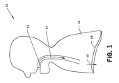
- FIG. 1 is a schematic diagram of the respiratory system of patient 10 during inspiration.
- the volume of thorax 16 is increased.
- a partial vacuum is created causing air to enter upper airway 12 and proceed in the direction of arrow 14.
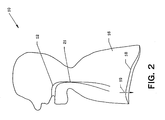
- FIG. 2 is a schematic diagram of the respiratory system of patient 10 during an obstructive apnea event.
- upper airway 12 tends to collapse producing the obstruction to air flow at point 21.
- the above referenced literature describes in detail the physiological processes associated with the collapse of upper airway 12.
- Patency of upper airway 12 is monitored by pressure sensor 42 and pressure sensor 48 coupled to implantable pulse generator 20 via cables 44 and 46, respectively. Stimulation of the musculature of upper airway 12 is accomplished via lead 52 coupled to electrode 50. All other referenced elements are as previously described.
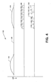
- FIG. 4 is a graphical representation 100 of the inputs and outputs of implantable pulse generator 20.
- Graph 108 represents the pressure differential between the upper airway and the thorax as measured between pressure sensor 42 and pressure sensor 48 wherein a decrease of pressure is shown by arrow 102.
- Node 104 shows a high pressure difference during inspiration which is indicative of an obstructive apnea event.
- Node 106 shows a much smaller differential as a result of stimulation of the musculature of the upper airway.
- the second graph shows a train of stimulation pulses, including pulses 110, 112, 114, 116, 118, 120, and 122, according to the prior art stimulation technique. Note that each of the pulses is of the same relatively high intensity. This stimulation tends to result in arousal of patient 10 from sleep.
- the bottom line shows a train of stimulation pulses generated in accordance with the present invention.
- First pulse 124 is of minimum intensity.
- Pulses 126 through 136 are gradually increased in amplitude until maximum intensity is reached with pulse 136. Note that by ramping from low to high intensity it is possible to reach a higher amplitude with less sensation to the patient than is possible with constant intensity stimulation. This permits a more effective contraction with less sensation due to the phenomenon of adaptation. It might also permit one to vary the frequency of stimulation (i.e. reduce frequency) to save energy and prolong the life of the pulse generator.
- FIG. 5 is a block diagram of implantable pulse generator 20.
- Sensor processing 140 determines the pressure differential between the upper airway and the thorax by comparing the measurements received from pressure sensors 42 and 48 via cables 44 and 46, respectively. Whenever this difference exceeds a given threshold, an output pulse is supplied to multi-vibrator 144 for pulse shaping.
- a pressure differential above a certain threshold value is identified by sensor processor 140 which outputs a signal to multivibrator 144.
- Multivibrator 144 then outputs a burst pulse of a predetermined length that determines the length of the desired stimulation pulse at the output 52, although this may vary depending on the operation of counter 146 (see below).
- the output signal encounters a second multivibrator 150 which establishes the frequency of the output pulses.
- the pulses are then shaped by the pulse former 152 into pulses of desired pulse width.
- the pulse frequency and pulse width may be determined substantially as shown in Fig. 4 pulses 110-122.
- the variable amplifier then converts these pulses into the ramped pulse forms shown in Fig. 4 pulses 124-136.
- the pulse width, pulse frequency and pulse duration parameters desired for the stimulatory pulse burst may be progammed into the device by telemetry signals to the pulse generator (as is conventionally accomplished in heart pacemakers) by implementation of appropriate telemetry circuitry in conjunction with elements 144, 150 and 152.
- Each inspiration cycle may be electrically monitored by electrode 56 coupled to lead 54 (see also Fig. 3).
- the signal is amplified by amplifier 142 and used to reset counter 146 and counter 160.
- Counter 146 is driven by clock 158 and may be used to delay generation of the stimulation pulse train to synchronize it with the inspiration cycle.
- gate 148 provides an output whenever multi-vibrator 144 indicates an obstruction is present as synchronized by counter 146.
- the role of sensing the inspiratory stimulus and the clock driven counters is to provide additional control over the timing of the stimulus and the ramping function.
- the counters 146 and 150 are reset by the start of the sensed activity of the diaphragm at the start of inspiration. Counter 146 may operate in one of two ways.
- a first way it is set low when reset and is only high after a predetermined number of clock cycles after reset. This may delay the onset of stimulation as stated above depending on the relative timing of the detected apnea.
- a second way it could be set high when reset and only go low after a predetermined number of clock cycles. It could therefore be used to cut off stimulation at a fixed time after the start of sensed inspiration.
- Counter 160 may similarly control the amplifier ramping activity.
- the counter 160 is reset upon sensed inspiration which causes the output to go low. After a predetermined number of clock cycles, the output is set high to begin the ramping of the variable amplifier.
- the amplitude of the pulse train starts higher and ends higher than if the amplifier is turned on at the same time the stimulatory pulses begin.
- These functions can also be controlled by programming desired values into the counters 146, 160 by telemetry signals to the pulse generator via appropriate telemetry circuitry.
- the appropriate timing of counters 146, 160 relative to a detected electrical activity in the diaphragm can be determined in use by the physician.
Abstract
Description
- The present invention relates generally to implantable medical devices, and more particularly, relates to implantable medical devices for the treatment of obstructive sleep apnea.
- The medical characteristics of sleep apnea have been known for some time. There are two generally recognized forms of the disease. The first is central sleep apnea which is associated with the failure of the body to automatically generate the neuro-muscular stimulation necessary to initiate and control a respiratory cycle at the proper time. Work associated with employing electrical stimulation to treat this condition is discussed in "Diaphragm Pacing: Present Status", by William W. L. Glenn, in Pace, Volume I, at pages 357-370 (July - September 1978).
- The second condition is known as obstructive sleep apnea. It is discussed at some length in "Obstructive Sleep Apnea: Diagnosis and Treatment", by Drs. Cook and Osguthorpe in Journal of South Carolina Medical Association, 81 (12): 647- 651 (December 1985).
- At present, a tracheostomy may be the treatment of choice for a number of patients when obstructive sleep apnea is severe. Some modern commercial systems now employ Continuous Positive Airway Pressure (CPAP). However, interest has recently been displayed in electrical stimulation of the muscle tissue along the upper airway during respiration. U.S. Patent No. 4,830,008 issued to Meer discusses a technique for electrical stimulation of the muscles of the upper airway in synchrony with the respiratory cycle. U.S. Patent No. 4,506,666 issued to Durkan discusses such stimulation in conjunction with pressurized airflow supplied by a respirator.
- Other applications of relevance to the present invention are U.S. Patent Application Serial No. 07/610,854, filed November 8, 1990, entitled "Muscle Tone"; U.S. Patent Application Serial No. 07/617,158, filed November 23, 1990, entitled "Multiple Stimulation Electrodes; U.S. Patent Application Serial No. 07/639,192, filed January 9, 1991, entitled "Servo Muscle Control"; and U.S. Patent Application Serial No. 07/671,513, filed March 19, 1991, entitled "Demand Apnea Control".
- The electrical stimulation of the prior art techniques, however, are primarily concerned with causing contractile motion of the stimulated muscle. This means that the stimulation energy must necessarily be relatively large, and the effects of the stimulation are directly cognizable by the patient.
- According to the present invention there is provided an apparatus comprising:
- a. determining means for determining the onset of an apnea event;
- b. generating means coupled to said determining means for generating a stimulation signal in response to said onset of said apnea event; and,
- c. control means coupled to said generating means for varying the amplitude of said stimulation signal from a minimum intensity to a maximum intensity.
- The present invention overcomes the deficiencies of the prior art by providing a system for treatment of obstructive sleep apnea having a minimum cognizable effect upon the patient. This is particularly important as the purpose of the therapy is to preclude disturbing the patient to ensure that the maximum benefit from sleep is derived.
- The system in one embodiment employs at least one sensor to monitor the respiration activity. In this way, the implantable pulse generator can determine the onset of an apnea event from indications within the respiratory cycle of the patient. In the preferred mode, the pressure differential between the thorax and the upper airway is measured. An increase in this differential above a given threshold signifies the onset of an apnea event.
- To treat the apnea event, the implantable pulse generator produces a train of pulses which is transferred to the muscles of the upper airway, for example, via an insulated lead and a suitable electrode. The train of pulses is initiated at a relatively low intensity with the pulse intensity increasing over time. In this manner, the patient is provided with a non-cognizable sensation produced by the stimulation signal.
- Since effective skeletal muscle stimulation depends upon both the amplitude and frequency of the stimulation pulses, a suitable frequency must be employed. By slowly increasing amplitude, the patient's sensory response to the stimuli exhibits adaptation, a well known phenomenon, that permits the brain to effectively block the pain response to noxious stimuli.
- A preferred embodiment of the present invention will now be described, by way of example only, and with reference to the following detailed description and accompanying drawings, in which like reference numerals designate like parts throughout the figures thereof and wherein:
- FIG. 1 is a schematic diagram of the respiratory system of a patient;
- FIG. 2 is a schematic diagram of the respiratory system showing an obstructive apnea event;
- FIG. 3 is a schematic diagram of the respiratory system of a patient having an obstructive apnea treatment system implanted;
- FIG. 4 is a graphical representation of the sensor input and implantable pulse generator output of the obstructive apnea treatment system; and,
- FIG. 5 is a block diagram of an implantable pulse generator according to an embodiment of the present invention.
- FIG. 1 is a schematic diagram of the respiratory system of
patient 10 during inspiration. As a result of the contraction ofdiaphragm 18 moving in the direction ofarrow 19, the volume ofthorax 16 is increased. A partial vacuum is created causing air to enterupper airway 12 and proceed in the direction ofarrow 14. - FIG. 2 is a schematic diagram of the respiratory system of
patient 10 during an obstructive apnea event. During inspiration,upper airway 12 tends to collapse producing the obstruction to air flow atpoint 21. The above referenced literature describes in detail the physiological processes associated with the collapse ofupper airway 12. - FIG. 3 is a schematic diagram of
patient 10 showing implantation of an electrical stimulation system for the treatment of both central and obstructive sleep apnea.Implantable pulse generator 20 is placed subcutaneously at a convenient position.Diaphragm 18 is electrically monitored viaelectrode 56 coupled to lead 54. This provides the means to synchronize any stimulation supplied to the inspiration cycle. - Patency of
upper airway 12 is monitored bypressure sensor 42 andpressure sensor 48 coupled toimplantable pulse generator 20 viacables upper airway 12 is accomplished vialead 52 coupled toelectrode 50. All other referenced elements are as previously described. - FIG. 4 is a
graphical representation 100 of the inputs and outputs ofimplantable pulse generator 20.Graph 108 represents the pressure differential between the upper airway and the thorax as measured betweenpressure sensor 42 andpressure sensor 48 wherein a decrease of pressure is shown byarrow 102.Node 104 shows a high pressure difference during inspiration which is indicative of an obstructive apnea event.Node 106 shows a much smaller differential as a result of stimulation of the musculature of the upper airway. - The second graph shows a train of stimulation pulses, including pulses 110, 112, 114, 116, 118, 120, and 122, according to the prior art stimulation technique. Note that each of the pulses is of the same relatively high intensity. This stimulation tends to result in arousal of
patient 10 from sleep. - The bottom line shows a train of stimulation pulses generated in accordance with the present invention.
First pulse 124 is of minimum intensity.Pulses 126 through 136 are gradually increased in amplitude until maximum intensity is reached withpulse 136. Note that by ramping from low to high intensity it is possible to reach a higher amplitude with less sensation to the patient than is possible with constant intensity stimulation. This permits a more effective contraction with less sensation due to the phenomenon of adaptation. It might also permit one to vary the frequency of stimulation (i.e. reduce frequency) to save energy and prolong the life of the pulse generator. - FIG. 5 is a block diagram of
implantable pulse generator 20.Sensor processing 140 determines the pressure differential between the upper airway and the thorax by comparing the measurements received frompressure sensors cables - In particular, a pressure differential above a certain threshold value is identified by
sensor processor 140 which outputs a signal tomultivibrator 144.Multivibrator 144 then outputs a burst pulse of a predetermined length that determines the length of the desired stimulation pulse at theoutput 52, although this may vary depending on the operation of counter 146 (see below). After passing through thegate 148, the output signal encounters asecond multivibrator 150 which establishes the frequency of the output pulses. The pulses are then shaped by the pulse former 152 into pulses of desired pulse width. Thus, by applying themultivibrator 144,multivibrator 150 and pulse former 152, the duration of the stimulation, the pulse frequency and pulse width may be determined substantially as shown in Fig. 4 pulses 110-122. The variable amplifier then converts these pulses into the ramped pulse forms shown in Fig. 4 pulses 124-136. - The pulse width, pulse frequency and pulse duration parameters desired for the stimulatory pulse burst may be progammed into the device by telemetry signals to the pulse generator (as is conventionally accomplished in heart pacemakers) by implementation of appropriate telemetry circuitry in conjunction with
elements - Each inspiration cycle may be electrically monitored by
electrode 56 coupled to lead 54 (see also Fig. 3). The signal is amplified byamplifier 142 and used to resetcounter 146 andcounter 160.Counter 146 is driven byclock 158 and may be used to delay generation of the stimulation pulse train to synchronize it with the inspiration cycle. Andgate 148 provides an output whenever multi-vibrator 144 indicates an obstruction is present as synchronized bycounter 146. - The role of sensing the inspiratory stimulus and the clock driven counters is to provide additional control over the timing of the stimulus and the ramping function. The
counters Counter 146 may operate in one of two ways. - In a first way, it is set low when reset and is only high after a predetermined number of clock cycles after reset. This may delay the onset of stimulation as stated above depending on the relative timing of the detected apnea. In a second way, it could be set high when reset and only go low after a predetermined number of clock cycles. It could therefore be used to cut off stimulation at a fixed time after the start of sensed inspiration.
-
Counter 160 may similarly control the amplifier ramping activity. Thecounter 160 is reset upon sensed inspiration which causes the output to go low. After a predetermined number of clock cycles, the output is set high to begin the ramping of the variable amplifier. By turning on the amplifier before the stimulatory pulses are created, the amplitude of the pulse train starts higher and ends higher than if the amplifier is turned on at the same time the stimulatory pulses begin. Providing the counter is set to go high at the correct time, this will generally occur as activity in the diaphragm will be sensed in advance of a sensed apnea. This provides some control over the amplitude of the stimulatory burst actually delivered to the upper airway. - The
counter 160 could also be set to go high as it is reset and then to go low after a predetermined number of clock cycles to turn off the variable amplifier, although this has no immediate physiological applications. - These functions can also be controlled by programming desired values into the
counters counters -
Counter 160 as reset byamplifier 142 controls the gain ofvariable amplifier 154. In this way, the amplification of the individual pulses output by pulse former 152 is varied to produce the variable intensity output according to the present invention (see also Fig. 4). One skilled in the art will readily appreciate the sort of circuitry required to enableamplifier 154 to provide a steadily increasing amplification upon receipt of a high signal fromcounter 160. In an alternative embodiment, thecounter 160 may provide a stepped output to adjust the gain of theamplifier 154.Amplifier 156 has a fixed gain and supplies the output to lead 52 for transmission to electrode 50 (see also Fig. 3). - Having thus described the preferred embodiments of the present invention, those of skill in the art will be readily able to apply the teachings found herein to yet other embodiments within the scope of the claims hereto attached as interpreted by the description.
Claims (6)
- An apparatus comprising:a. determining means (140) for determining the onset of an apnea event;b. generating means (144, 150, 152) coupled to said determining means for generating a stimulation signal in response to said onset of said apnea event; and,c. control means (160, 154) coupled to said generating means for varying the amplitude of said stimulation signal from a minimum intensity to a maximum intensity.
- An apparatus according to claim 1 further comprising synchronising means (142, 146) coupled to said generating means for synchronizing said stimulation signal with an inspiration cycle.
- An apparatus according to claim 2 wherein said synchronizing means comprises an electrode for sensing contraction of the diaphragm.
- An apparatus according to any preceding claim wherein said control means operates to produce said minimum intensity at a beginning of said stimulation signal.
- An apparatus according to any preceding claim wherein said determining means comprises means for measuring a pressure differential between the thorax and the upper airway.
- An apparatus according to claim 5 wherein said measuring means comprises a first pressure sensor for location in said thorax and a second pressure sensor for location in said upper airway.
Applications Claiming Priority (2)
| Application Number | Priority Date | Filing Date | Title |
|---|---|---|---|
| US07/679,120 US5215082A (en) | 1991-04-02 | 1991-04-02 | Implantable apnea generator with ramp on generator |
| US679120 | 1991-04-02 |
Publications (3)
| Publication Number | Publication Date |
|---|---|
| EP0507580A2 true EP0507580A2 (en) | 1992-10-07 |
| EP0507580A3 EP0507580A3 (en) | 1993-03-24 |
| EP0507580B1 EP0507580B1 (en) | 1996-07-31 |
Family
ID=24725640
Family Applications (1)
| Application Number | Title | Priority Date | Filing Date |
|---|---|---|---|
| EP92302899A Expired - Lifetime EP0507580B1 (en) | 1991-04-02 | 1992-04-02 | Implantable apnea generator with ramp on generator |
Country Status (3)
| Country | Link |
|---|---|
| US (1) | US5215082A (en) |
| EP (1) | EP0507580B1 (en) |
| DE (1) | DE69212520T2 (en) |
Cited By (2)
| Publication number | Priority date | Publication date | Assignee | Title |
|---|---|---|---|---|
| EP1524007A1 (en) * | 2003-10-17 | 2005-04-20 | Alfred E. Mann Foundation for Scientific Research | Method and system for treating sleep apnea |
| US7697990B2 (en) | 2004-02-20 | 2010-04-13 | Resmed Limited | Method and apparatus for detection and treatment of respiratory disorder by implantable device |
Families Citing this family (87)
| Publication number | Priority date | Publication date | Assignee | Title |
|---|---|---|---|---|
| US5259373A (en) * | 1989-05-19 | 1993-11-09 | Puritan-Bennett Corporation | Inspiratory airway pressure system controlled by the detection and analysis of patient airway sounds |
| US5490502A (en) * | 1992-05-07 | 1996-02-13 | New York University | Method and apparatus for optimizing the continuous positive airway pressure for treating obstructive sleep apnea |
| US5549655A (en) | 1994-09-21 | 1996-08-27 | Medtronic, Inc. | Method and apparatus for synchronized treatment of obstructive sleep apnea |
| US5540731A (en) * | 1994-09-21 | 1996-07-30 | Medtronic, Inc. | Method and apparatus for pressure detecting and treating obstructive airway disorders |
| US5522862A (en) * | 1994-09-21 | 1996-06-04 | Medtronic, Inc. | Method and apparatus for treating obstructive sleep apnea |
| US5540732A (en) * | 1994-09-21 | 1996-07-30 | Medtronic, Inc. | Method and apparatus for impedance detecting and treating obstructive airway disorders |
| US5591216A (en) * | 1995-05-19 | 1997-01-07 | Medtronic, Inc. | Method for treatment of sleep apnea by electrical stimulation |
| US6021352A (en) * | 1996-06-26 | 2000-02-01 | Medtronic, Inc, | Diagnostic testing methods and apparatus for implantable therapy devices |
| US5944680A (en) * | 1996-06-26 | 1999-08-31 | Medtronic, Inc. | Respiratory effort detection method and apparatus |
| US5895360A (en) * | 1996-06-26 | 1999-04-20 | Medtronic, Inc. | Gain control for a periodic signal and method regarding same |
| US6132384A (en) * | 1996-06-26 | 2000-10-17 | Medtronic, Inc. | Sensor, method of sensor implant and system for treatment of respiratory disorders |
| US6099479A (en) * | 1996-06-26 | 2000-08-08 | Medtronic, Inc. | Method and apparatus for operating therapy system |
| US6093158A (en) * | 1997-05-15 | 2000-07-25 | Morris; Donald E. | Systems for modifying behavioral disorders |
| US6212435B1 (en) | 1998-11-13 | 2001-04-03 | Respironics, Inc. | Intraoral electromuscular stimulation device and method |
| US6949075B2 (en) * | 2002-12-27 | 2005-09-27 | Cardiac Pacemakers, Inc. | Apparatus and method for detecting lung sounds using an implanted device |
| US20050080348A1 (en) * | 2003-09-18 | 2005-04-14 | Stahmann Jeffrey E. | Medical event logbook system and method |
| US7025730B2 (en) | 2003-01-10 | 2006-04-11 | Medtronic, Inc. | System and method for automatically monitoring and delivering therapy for sleep-related disordered breathing |
| US7499750B2 (en) | 2003-04-11 | 2009-03-03 | Cardiac Pacemakers, Inc. | Noise canceling cardiac electrodes |
| US7155278B2 (en) * | 2003-04-21 | 2006-12-26 | Medtronic, Inc. | Neurostimulation to treat effects of sleep apnea |
| US7336996B2 (en) * | 2003-09-18 | 2008-02-26 | Cardiac Pacemakers, Inc. | Rate regularization of cardiac pacing for disordered breathing therapy |
| US8192376B2 (en) | 2003-08-18 | 2012-06-05 | Cardiac Pacemakers, Inc. | Sleep state classification |
| US7532934B2 (en) * | 2003-09-18 | 2009-05-12 | Cardiac Pacemakers, Inc. | Snoring detection system and method |
| US7572225B2 (en) * | 2003-09-18 | 2009-08-11 | Cardiac Pacemakers, Inc. | Sleep logbook |
| US7757690B2 (en) * | 2003-09-18 | 2010-07-20 | Cardiac Pacemakers, Inc. | System and method for moderating a therapy delivered during sleep using physiologic data acquired during non-sleep |
| US20050142070A1 (en) * | 2003-09-18 | 2005-06-30 | Hartley Jesse W. | Methods and systems for assessing pulmonary disease with drug therapy control |
| US7680537B2 (en) * | 2003-08-18 | 2010-03-16 | Cardiac Pacemakers, Inc. | Therapy triggered by prediction of disordered breathing |
| US7668591B2 (en) * | 2003-09-18 | 2010-02-23 | Cardiac Pacemakers, Inc. | Automatic activation of medical processes |
| US8002553B2 (en) | 2003-08-18 | 2011-08-23 | Cardiac Pacemakers, Inc. | Sleep quality data collection and evaluation |
| US7610094B2 (en) | 2003-09-18 | 2009-10-27 | Cardiac Pacemakers, Inc. | Synergistic use of medical devices for detecting medical disorders |
| US7396333B2 (en) | 2003-08-18 | 2008-07-08 | Cardiac Pacemakers, Inc. | Prediction of disordered breathing |
| US8251061B2 (en) * | 2003-09-18 | 2012-08-28 | Cardiac Pacemakers, Inc. | Methods and systems for control of gas therapy |
| US7468040B2 (en) * | 2003-09-18 | 2008-12-23 | Cardiac Pacemakers, Inc. | Methods and systems for implantably monitoring external breathing therapy |
| US7662101B2 (en) | 2003-09-18 | 2010-02-16 | Cardiac Pacemakers, Inc. | Therapy control based on cardiopulmonary status |
| US8606356B2 (en) | 2003-09-18 | 2013-12-10 | Cardiac Pacemakers, Inc. | Autonomic arousal detection system and method |
| US7887493B2 (en) | 2003-09-18 | 2011-02-15 | Cardiac Pacemakers, Inc. | Implantable device employing movement sensing for detecting sleep-related disorders |
| US7720541B2 (en) * | 2003-08-18 | 2010-05-18 | Cardiac Pacemakers, Inc. | Adaptive therapy for disordered breathing |
| US7591265B2 (en) | 2003-09-18 | 2009-09-22 | Cardiac Pacemakers, Inc. | Coordinated use of respiratory and cardiac therapies for sleep disordered breathing |
| US7967756B2 (en) * | 2003-09-18 | 2011-06-28 | Cardiac Pacemakers, Inc. | Respiratory therapy control based on cardiac cycle |
| US7575553B2 (en) | 2003-09-18 | 2009-08-18 | Cardiac Pacemakers, Inc. | Methods and systems for assessing pulmonary disease |
| US7469697B2 (en) * | 2003-09-18 | 2008-12-30 | Cardiac Pacemakers, Inc. | Feedback system and method for sleep disordered breathing therapy |
| US7510531B2 (en) | 2003-09-18 | 2009-03-31 | Cardiac Pacemakers, Inc. | System and method for discrimination of central and obstructive disordered breathing events |
| EP1670547B1 (en) | 2003-08-18 | 2008-11-12 | Cardiac Pacemakers, Inc. | Patient monitoring system |
| US8467876B2 (en) * | 2003-10-15 | 2013-06-18 | Rmx, Llc | Breathing disorder detection and therapy delivery device and method |
| US7979128B2 (en) * | 2003-10-15 | 2011-07-12 | Rmx, Llc | Device and method for gradually controlling breathing |
| US8244358B2 (en) * | 2003-10-15 | 2012-08-14 | Rmx, Llc | Device and method for treating obstructive sleep apnea |
| US20080161878A1 (en) * | 2003-10-15 | 2008-07-03 | Tehrani Amir J | Device and method to for independently stimulating hemidiaphragms |
| US9259573B2 (en) * | 2003-10-15 | 2016-02-16 | Rmx, Llc | Device and method for manipulating exhalation |
| US8160711B2 (en) | 2003-10-15 | 2012-04-17 | Rmx, Llc | Multimode device and method for controlling breathing |
| US8140164B2 (en) * | 2003-10-15 | 2012-03-20 | Rmx, Llc | Therapeutic diaphragm stimulation device and method |
| US7970475B2 (en) | 2003-10-15 | 2011-06-28 | Rmx, Llc | Device and method for biasing lung volume |
| US8265759B2 (en) * | 2003-10-15 | 2012-09-11 | Rmx, Llc | Device and method for treating disorders of the cardiovascular system or heart |
| US7454250B1 (en) | 2004-04-21 | 2008-11-18 | Pacesetter, Inc. | System and method for applying therapy during hyperpnea phase of periodic breathing using an implantable medical device |
| US7245971B2 (en) * | 2004-04-21 | 2007-07-17 | Pacesetter, Inc. | System and method for applying therapy during hyperpnea phase of periodic breathing using an implantable medical device |
| US7690378B1 (en) * | 2004-07-21 | 2010-04-06 | Pacesetter, Inc. | Methods, systems and devices for monitoring respiratory disorders |
| US7996072B2 (en) | 2004-12-21 | 2011-08-09 | Cardiac Pacemakers, Inc. | Positionally adaptable implantable cardiac device |
| JP2006185060A (en) * | 2004-12-27 | 2006-07-13 | Fujitsu Ltd | Method for inputting password |
| US7680534B2 (en) | 2005-02-28 | 2010-03-16 | Cardiac Pacemakers, Inc. | Implantable cardiac device with dyspnea measurement |
| US7630755B2 (en) | 2005-05-04 | 2009-12-08 | Cardiac Pacemakers Inc. | Syncope logbook and method of using same |
| US7644714B2 (en) | 2005-05-27 | 2010-01-12 | Apnex Medical, Inc. | Devices and methods for treating sleep disorders |
| US20070055115A1 (en) * | 2005-09-08 | 2007-03-08 | Jonathan Kwok | Characterization of sleep disorders using composite patient data |
| US20070118180A1 (en) | 2005-11-18 | 2007-05-24 | Quan Ni | Cardiac resynchronization therapy for improved hemodynamics based on disordered breathing detection |
| US7519409B2 (en) * | 2005-12-29 | 2009-04-14 | Medtronic, Inc. | Implantable cell/tissue-based biosensing device |
| WO2007098200A2 (en) * | 2006-02-16 | 2007-08-30 | Imthera Medical, Inc. | An rfid-based apparatus, system, and method for therapeutic treatment of obstructive sleep apnea |
| US7678058B2 (en) * | 2006-06-22 | 2010-03-16 | Cardiac Pacemakers, Inc. | Apnea type determining apparatus and method |
| US8360983B2 (en) | 2006-06-22 | 2013-01-29 | Cardiac Pacemakers, Inc. | Apnea type determining apparatus and method |
| US8688219B2 (en) | 2006-07-28 | 2014-04-01 | Medronic, Inc. | Dynamic sampling |
| US8417343B2 (en) | 2006-10-13 | 2013-04-09 | Apnex Medical, Inc. | Obstructive sleep apnea treatment devices, systems and methods |
| US9186511B2 (en) | 2006-10-13 | 2015-11-17 | Cyberonics, Inc. | Obstructive sleep apnea treatment devices, systems and methods |
| US9205262B2 (en) | 2011-05-12 | 2015-12-08 | Cyberonics, Inc. | Devices and methods for sleep apnea treatment |
| US9744354B2 (en) | 2008-12-31 | 2017-08-29 | Cyberonics, Inc. | Obstructive sleep apnea treatment devices, systems and methods |
| US8855771B2 (en) | 2011-01-28 | 2014-10-07 | Cyberonics, Inc. | Screening devices and methods for obstructive sleep apnea therapy |
| US9913982B2 (en) | 2011-01-28 | 2018-03-13 | Cyberonics, Inc. | Obstructive sleep apnea treatment devices, systems and methods |
| US20080109047A1 (en) * | 2006-10-26 | 2008-05-08 | Pless Benjamin D | Apnea treatment device |
| US8280513B2 (en) * | 2006-12-22 | 2012-10-02 | Rmx, Llc | Device and method to treat flow limitations |
| WO2009048580A1 (en) * | 2007-10-09 | 2009-04-16 | Imthera Medical, Inc. | Apparatus, system, and method for selective stimulation |
| BRPI0920548B8 (en) | 2008-10-09 | 2021-06-22 | Imthera Medical Inc | device to control the position of a patient's tongue |
| EP3184045B1 (en) | 2008-11-19 | 2023-12-06 | Inspire Medical Systems, Inc. | System treating sleep disordered breathing |
| US20110112601A1 (en) | 2009-11-10 | 2011-05-12 | Imthera Medical, Inc. | System for stimulating a hypoglossal nerve for controlling the position of a patient's tongue |
| US20150039045A1 (en) | 2011-08-11 | 2015-02-05 | Inspire Medical Systems, Inc. | Method and system for applying stimulation in treating sleep disordered breathing |
| US9724018B2 (en) | 2011-10-27 | 2017-08-08 | Medtronic Cryocath Lp | Method for monitoring phrenic nerve function |
| US10064564B2 (en) | 2013-08-23 | 2018-09-04 | Medtronic Cryocath Lp | Method of CMAP monitoring |
| US11383083B2 (en) | 2014-02-11 | 2022-07-12 | Livanova Usa, Inc. | Systems and methods of detecting and treating obstructive sleep apnea |
| WO2016033245A1 (en) | 2014-08-26 | 2016-03-03 | Rmx, Llc | Devices and methods for reducing intrathoracic pressure |
| CN113908438A (en) | 2015-03-19 | 2022-01-11 | 启迪医疗仪器公司 | Stimulation for treating sleep disordered breathing |
| WO2018089789A1 (en) | 2016-11-10 | 2018-05-17 | The Research Foundation For The State University Of New York | System, method and biomarkers for airway obstruction |
| WO2018144631A1 (en) | 2017-02-01 | 2018-08-09 | The Alfred E. Mann Foundation For Scientific Research | Stimulator systems and methods for obstructive sleep apnea |
| US11266838B1 (en) | 2019-06-21 | 2022-03-08 | Rmx, Llc | Airway diagnostics utilizing phrenic nerve stimulation device and method |
Citations (2)
| Publication number | Priority date | Publication date | Assignee | Title |
|---|---|---|---|---|
| DE2908365A1 (en) * | 1979-03-03 | 1980-09-11 | Pichl & Schulte Datron Elect | Diagnostic and therapeutic stimulating appts. for paralysed muscles - has pulse generating circuit with changeover switch, generating periodical pulse trains of opposite sign with DC zero compensation |
| WO1991005583A1 (en) * | 1989-10-16 | 1991-05-02 | Brunswick Biomedical Technologies, Inc. | Method and apparatus for controlling breathing |
Family Cites Families (4)
| Publication number | Priority date | Publication date | Assignee | Title |
|---|---|---|---|---|
| US4506666A (en) * | 1982-12-03 | 1985-03-26 | Kircaldie, Randall And Mcnab | Method and apparatus for rectifying obstructive apnea |
| US4827935A (en) * | 1986-04-24 | 1989-05-09 | Purdue Research Foundation | Demand electroventilator |
| US4830008A (en) * | 1987-04-24 | 1989-05-16 | Meer Jeffrey A | Method and system for treatment of sleep apnea |
| JP2794196B2 (en) * | 1989-06-20 | 1998-09-03 | チェスト株式会社 | Apnea prevention stimulator |
-
1991
- 1991-04-02 US US07/679,120 patent/US5215082A/en not_active Expired - Lifetime
-
1992
- 1992-04-02 DE DE69212520T patent/DE69212520T2/en not_active Expired - Fee Related
- 1992-04-02 EP EP92302899A patent/EP0507580B1/en not_active Expired - Lifetime
Patent Citations (2)
| Publication number | Priority date | Publication date | Assignee | Title |
|---|---|---|---|---|
| DE2908365A1 (en) * | 1979-03-03 | 1980-09-11 | Pichl & Schulte Datron Elect | Diagnostic and therapeutic stimulating appts. for paralysed muscles - has pulse generating circuit with changeover switch, generating periodical pulse trains of opposite sign with DC zero compensation |
| WO1991005583A1 (en) * | 1989-10-16 | 1991-05-02 | Brunswick Biomedical Technologies, Inc. | Method and apparatus for controlling breathing |
Non-Patent Citations (1)
| Title |
|---|
| ASAIO TRANSACTIONS vol. 34, no. 3, September 1988, HAGERSTOWN,MD,(US) pages 674 - 680 MICHAEL BRONIATOWSKI ET.AL. 'New Horizons in Dynamic Rehabilitation of Paralyzed Laryngeal Functions' * |
Cited By (3)
| Publication number | Priority date | Publication date | Assignee | Title |
|---|---|---|---|---|
| EP1524007A1 (en) * | 2003-10-17 | 2005-04-20 | Alfred E. Mann Foundation for Scientific Research | Method and system for treating sleep apnea |
| US7697990B2 (en) | 2004-02-20 | 2010-04-13 | Resmed Limited | Method and apparatus for detection and treatment of respiratory disorder by implantable device |
| US9050024B2 (en) | 2004-02-20 | 2015-06-09 | Redmed Limited | Method and apparatus for detection and treatment of respiratory disorder by implantable device |
Also Published As
| Publication number | Publication date |
|---|---|
| US5215082A (en) | 1993-06-01 |
| EP0507580A3 (en) | 1993-03-24 |
| DE69212520D1 (en) | 1996-09-05 |
| DE69212520T2 (en) | 1997-03-06 |
| EP0507580B1 (en) | 1996-07-31 |
Similar Documents
| Publication | Publication Date | Title |
|---|---|---|
| EP0507580B1 (en) | Implantable apnea generator with ramp on generator | |
| EP0494787B1 (en) | Servo muscle control | |
| US5174287A (en) | Airway feedback measurement system responsive to detected inspiration and obstructive apnea event | |
| US5211173A (en) | Servo muscle control | |
| US5158080A (en) | Muscle tone | |
| US5133354A (en) | Method and apparatus for improving muscle tone | |
| US5540732A (en) | Method and apparatus for impedance detecting and treating obstructive airway disorders | |
| US5146918A (en) | Demand apnea control of central and obstructive sleep apnea | |
| US5540731A (en) | Method and apparatus for pressure detecting and treating obstructive airway disorders | |
| US5540733A (en) | Method and apparatus for detecting and treating obstructive sleep apnea | |
| US5123425A (en) | Obstructive sleep apnea collar | |
| US4830008A (en) | Method and system for treatment of sleep apnea | |
| US8160711B2 (en) | Multimode device and method for controlling breathing | |
| US8244358B2 (en) | Device and method for treating obstructive sleep apnea | |
| US7979128B2 (en) | Device and method for gradually controlling breathing | |
| US5549655A (en) | Method and apparatus for synchronized treatment of obstructive sleep apnea | |
| EP0190195B1 (en) | Process and apparatus for diaphragmic stimulation | |
| EP0702978A2 (en) | Apparatus for treating obstructive sleep apnea | |
| JPH09215757A (en) | Device for medical use for processing upper airway fault | |
| CA1323069C (en) | Method and system for treatment of sleep apnea syndrome |
Legal Events
| Date | Code | Title | Description |
|---|---|---|---|
| PUAI | Public reference made under article 153(3) epc to a published international application that has entered the european phase |
Free format text: ORIGINAL CODE: 0009012 |
|
| AK | Designated contracting states |
Kind code of ref document: A2 Designated state(s): DE FR GB NL |
|
| PUAL | Search report despatched |
Free format text: ORIGINAL CODE: 0009013 |
|
| AK | Designated contracting states |
Kind code of ref document: A3 Designated state(s): DE FR GB NL |
|
| 17P | Request for examination filed |
Effective date: 19930814 |
|
| 17Q | First examination report despatched |
Effective date: 19950904 |
|
| GRAH | Despatch of communication of intention to grant a patent |
Free format text: ORIGINAL CODE: EPIDOS IGRA |
|
| GRAH | Despatch of communication of intention to grant a patent |
Free format text: ORIGINAL CODE: EPIDOS IGRA |
|
| GRAA | (expected) grant |
Free format text: ORIGINAL CODE: 0009210 |
|
| AK | Designated contracting states |
Kind code of ref document: B1 Designated state(s): DE FR GB NL |
|
| REF | Corresponds to: |
Ref document number: 69212520 Country of ref document: DE Date of ref document: 19960905 |
|
| ET | Fr: translation filed | ||
| PLBE | No opposition filed within time limit |
Free format text: ORIGINAL CODE: 0009261 |
|
| STAA | Information on the status of an ep patent application or granted ep patent |
Free format text: STATUS: NO OPPOSITION FILED WITHIN TIME LIMIT |
|
| 26N | No opposition filed | ||
| REG | Reference to a national code |
Ref country code: GB Ref legal event code: IF02 |
|
| PGFP | Annual fee paid to national office [announced via postgrant information from national office to epo] |
Ref country code: GB Payment date: 20040312 Year of fee payment: 13 |
|
| PGFP | Annual fee paid to national office [announced via postgrant information from national office to epo] |
Ref country code: FR Payment date: 20040402 Year of fee payment: 13 |
|
| PGFP | Annual fee paid to national office [announced via postgrant information from national office to epo] |
Ref country code: DE Payment date: 20040430 Year of fee payment: 13 |
|
| PGFP | Annual fee paid to national office [announced via postgrant information from national office to epo] |
Ref country code: NL Payment date: 20050316 Year of fee payment: 14 |
|
| PG25 | Lapsed in a contracting state [announced via postgrant information from national office to epo] |
Ref country code: GB Free format text: LAPSE BECAUSE OF NON-PAYMENT OF DUE FEES Effective date: 20050402 |
|
| PG25 | Lapsed in a contracting state [announced via postgrant information from national office to epo] |
Ref country code: DE Free format text: LAPSE BECAUSE OF NON-PAYMENT OF DUE FEES Effective date: 20051101 |
|
| GBPC | Gb: european patent ceased through non-payment of renewal fee |
Effective date: 20050402 |
|
| PG25 | Lapsed in a contracting state [announced via postgrant information from national office to epo] |
Ref country code: FR Free format text: LAPSE BECAUSE OF NON-PAYMENT OF DUE FEES Effective date: 20051230 |
|
| REG | Reference to a national code |
Ref country code: FR Ref legal event code: ST Effective date: 20051230 |
|
| PG25 | Lapsed in a contracting state [announced via postgrant information from national office to epo] |
Ref country code: NL Free format text: LAPSE BECAUSE OF NON-PAYMENT OF DUE FEES Effective date: 20061101 |
|
| NLV4 | Nl: lapsed or anulled due to non-payment of the annual fee |
Effective date: 20061101 |