EP0512799A2 - Pagewidth thermal ink jet printhead - Google Patents
Pagewidth thermal ink jet printhead Download PDFInfo
- Publication number
- EP0512799A2 EP0512799A2 EP92304052A EP92304052A EP0512799A2 EP 0512799 A2 EP0512799 A2 EP 0512799A2 EP 92304052 A EP92304052 A EP 92304052A EP 92304052 A EP92304052 A EP 92304052A EP 0512799 A2 EP0512799 A2 EP 0512799A2
- Authority
- EP
- European Patent Office
- Prior art keywords
- printhead
- bar
- subunits
- pagewidth
- ink
- Prior art date
- Legal status (The legal status is an assumption and is not a legal conclusion. Google has not performed a legal analysis and makes no representation as to the accuracy of the status listed.)
- Granted
Links
- 238000007639 printing Methods 0.000 claims abstract description 23
- 238000010438 heat treatment Methods 0.000 claims description 36
- 230000000149 penetrating effect Effects 0.000 claims description 2
- 239000000758 substrate Substances 0.000 description 20
- 235000012431 wafers Nutrition 0.000 description 15
- XUIMIQQOPSSXEZ-UHFFFAOYSA-N Silicon Chemical compound [Si] XUIMIQQOPSSXEZ-UHFFFAOYSA-N 0.000 description 14
- 229910052710 silicon Inorganic materials 0.000 description 14
- 239000010703 silicon Substances 0.000 description 14
- 238000009826 distribution Methods 0.000 description 5
- OKTJSMMVPCPJKN-UHFFFAOYSA-N Carbon Chemical compound [C] OKTJSMMVPCPJKN-UHFFFAOYSA-N 0.000 description 4
- PXHVJJICTQNCMI-UHFFFAOYSA-N Nickel Chemical compound [Ni] PXHVJJICTQNCMI-UHFFFAOYSA-N 0.000 description 4
- 239000000853 adhesive Substances 0.000 description 4
- 230000001070 adhesive effect Effects 0.000 description 4
- 229910002804 graphite Inorganic materials 0.000 description 4
- 239000010439 graphite Substances 0.000 description 4
- 238000000034 method Methods 0.000 description 4
- 238000003491 array Methods 0.000 description 3
- 230000008901 benefit Effects 0.000 description 3
- 230000000694 effects Effects 0.000 description 3
- 238000007641 inkjet printing Methods 0.000 description 3
- 239000000463 material Substances 0.000 description 3
- 230000008569 process Effects 0.000 description 3
- 238000004891 communication Methods 0.000 description 2
- 238000010276 construction Methods 0.000 description 2
- 238000005530 etching Methods 0.000 description 2
- 229910052759 nickel Inorganic materials 0.000 description 2
- 229920002120 photoresistant polymer Polymers 0.000 description 2
- 240000000254 Agrostemma githago Species 0.000 description 1
- 235000009899 Agrostemma githago Nutrition 0.000 description 1
- 239000004593 Epoxy Substances 0.000 description 1
- 230000009471 action Effects 0.000 description 1
- 238000004458 analytical method Methods 0.000 description 1
- 238000005452 bending Methods 0.000 description 1
- 230000008859 change Effects 0.000 description 1
- 230000008878 coupling Effects 0.000 description 1
- 238000010168 coupling process Methods 0.000 description 1
- 238000005859 coupling reaction Methods 0.000 description 1
- 238000005336 cracking Methods 0.000 description 1
- 230000001627 detrimental effect Effects 0.000 description 1
- 238000001035 drying Methods 0.000 description 1
- 238000005516 engineering process Methods 0.000 description 1
- 230000009969 flowable effect Effects 0.000 description 1
- 239000012530 fluid Substances 0.000 description 1
- 239000007788 liquid Substances 0.000 description 1
- 238000004519 manufacturing process Methods 0.000 description 1
- 239000013618 particulate matter Substances 0.000 description 1
- 238000002161 passivation Methods 0.000 description 1
- 238000007789 sealing Methods 0.000 description 1
- 238000009834 vaporization Methods 0.000 description 1
- 230000008016 vaporization Effects 0.000 description 1
- 230000037303 wrinkles Effects 0.000 description 1
Images


Classifications
-
- B—PERFORMING OPERATIONS; TRANSPORTING
- B41—PRINTING; LINING MACHINES; TYPEWRITERS; STAMPS
- B41J—TYPEWRITERS; SELECTIVE PRINTING MECHANISMS, i.e. MECHANISMS PRINTING OTHERWISE THAN FROM A FORME; CORRECTION OF TYPOGRAPHICAL ERRORS
- B41J2/00—Typewriters or selective printing mechanisms characterised by the printing or marking process for which they are designed
- B41J2/005—Typewriters or selective printing mechanisms characterised by the printing or marking process for which they are designed characterised by bringing liquid or particles selectively into contact with a printing material
- B41J2/01—Ink jet
- B41J2/135—Nozzles
- B41J2/145—Arrangement thereof
- B41J2/155—Arrangement thereof for line printing
-
- B—PERFORMING OPERATIONS; TRANSPORTING
- B41—PRINTING; LINING MACHINES; TYPEWRITERS; STAMPS
- B41J—TYPEWRITERS; SELECTIVE PRINTING MECHANISMS, i.e. MECHANISMS PRINTING OTHERWISE THAN FROM A FORME; CORRECTION OF TYPOGRAPHICAL ERRORS
- B41J2202/00—Embodiments of or processes related to ink-jet or thermal heads
- B41J2202/01—Embodiments of or processes related to ink-jet heads
- B41J2202/20—Modules
Definitions
- This invention relates to thermal ink jet printing on demand, and more particularly to pagewidth thermal ink jet printheads.
- thermal, drop-on-demand, ink jet printheads There are two general configurations for thermal, drop-on-demand, ink jet printheads.
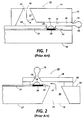
- droplets are propelled from nozzles in a direction parallel to the flow of ink in ink channels and parallel to the surface of the bubble-generating heating elements of the printhead, such as, for example, the printhead configuration disclosed in U.S. Reissue Patent RE 32,572 to Hawkins et al. and schematically shown in Figure 1.
- This configuration is sometimes referred to as an edge or side shooter.
- the other thermal ink jet configuration propels droplets from nozzles in a direction normal to the surface of the bubble-generating heating elements such as, for example, the printhead disclosed in U.S. Patent number 4,568,953 to Aoki et al.
- This latter configuration is sometimes referred as a roofshooter and is schematically illustrated in Figure 2. It can be seen that a fundamental difference lies in the direction of droplet ejection.
- the sideshooter configuration ejects droplets in the plane of the substrate having the heating elements, while the roofshooter ejects droplets out of the plane of the substrate having the heating elements and in a direction normal thereto.
- U.S. Reissue Patent number RE 32,572 to Hawkins et al. discloses a sideshooter configuration for a thermal ink jet printhead and several fabricating processes therefor.
- Each printhead is composed of two parts aligned and bonded together.
- One part is a substantially flat substrate which contains on the surface thereof a linear array of heating elements and addressing electrodes, and the second part is a substrate having at least one recess anisotropically etched therein to serve as an ink supply manifold when the two parts are bonded together.
- a linear array of parallel grooves is also formed in the second part so that one end of each of the grooves communicates with the manifold recess and the other end is open for use as an ink droplet expelling nozzle.
- printheads can be made simultaneously by producing a plurality of sets of heating element arrays with their addressing electrodes on a silicon wafer. A corresponding plurality of sets of channels and associated manifolds are produced in a second silicon wafer. The two wafers are aligned and bonded together and then diced into many separate printheads.
- the printheads may be used in carriage-type printers for printing swaths of information and then stepping the recording medium a distance of one swath and continuing to print adjacent swaths of information until a full page of information is printed.
- the printheads may be considered as subunits of a pagewidth printhead and arranged on a structural image bar for pagewidth printing. In pagewidth printing, the printheads may be assembled by abutting a plurality of the printhead subunits end-to-end on the image bar or staggering them on two separate image bars or on opposite sides of the same image bar.
- U.S. Patent number 4,568,953 to Aoki et al. discloses a thermal ink jet printhead in which the droplets are ejected on demand through nozzles aligned above and parallel to the heating elements, so that the droplet trajectories are normal to the heating elements.
- the ink is circulated through the printhead and internal passageways having cross-sectional flow areas larger than the nozzles. This enables particulate matter larger than the nozzles to pass and be swept away by the circulating ink entering and leaving the printhead through inlet and outlet tubes.
- U.S. Patent number 4,789,425 to Drake et al. discloses a roofshooter-type thermal ink jet printhead, wherein each printhead comprises a silicon heater plate and a fluid directing structural member.
- the heater plate has a linear array of heating elements, associated addressing electrodes, and an elongated ink-filled hole parallel with the heating element array.
- the structural member contains at least one recessed cavity, a plurality of nozzles, and a plurality of parallel walls within the recessed cavity which define individual ink channels for directing the ink to the nozzles.
- the recessed cavity and fill hole are in communication with each other and form the ink reservoir within the printhead.
- the ink holding capacity of the fill hole is larger than that of the recessed cavity.
- the fill hole is precisely formed and positioned within the heater plate by anisotropic etching.
- the structural member may be fabricated either from two layers of photoresist, a two-stage flat nickel electroform, or a single photoresist layer and a single stage flat nickel electroform.
- U.S. Patent number 4,829,324 to Drake et al. discloses a large array ink jet printhead having two basic parts, one containing an array of heating elements and addressing electrodes on the surface thereof, and the other containing the liquid ink handling system. At least the part containing the ink handling system is silicon and is assembled from generally identical subunits aligned and bonded side-by-side on the part surface having the heating element array.
- a plurality of channel plate subunits is anisotropically etched in a silicon wafer and a plurality of heating element subunits is formed on another silicon wafer.
- the heating element wafer is also anisotropically etched with elongated slots. The wafers are aligned and bonded together, then diced into complete printhead subunits which have abutting side surfaces that are ⁇ 111 ⁇ planes for accurate side-by-side assembly.
- U.S. Patent number 4,851,371 to Fisher et al. and U.S. Patent number 4,935,750 to Hawkins disclose a cost effective method of fabricating a large array or pagewidth silicon device having high resolution.
- the pagewidth device is assembled by abutting silicon device subunits such as image sensors or thermal ink jet printheads.
- the subunits are fully functional small printheads comprising an ink flow directing channel plate and a heating element plate which are bonded together.
- a plurality of individual printhead subunits is obtained by dicing aligned and bonded channel wafers and heating element wafers.
- U.S. Patent 4,935,750 discloses how a pagewidth printhead may be further stabilized and strengthened by assembly of printhead subunits on a flat structural member. Assembly of the pagewidth printhead is complete when an elongated hollow conduit means having a plurality of outlets is mounted over the subunits with each outlet aligned with a one of the inlets of the printhead subunits. Gaskets are sealed to the outlets of the conduit means by, for example, an adhesive earlier screened onto the gasket. The gasket sealingly surrounds the printhead subunit inlet and outlets of the conduit means and prevents the ink supplied to the printhead subunits via the conduit means from leaking at the interface therebetween.
- U.S. Patent number 4,985,710 to Drake et al. discloses a "roofshooter" pagewidth printhead for use in a thermal ink jet printing device fabricated from a plurality of subunits, each being produced by bonding a heater substrate, having an architecture including an array of heater elements and an etched ink feed slot, to a secondary substrate having a series of spaced feed hole openings to form a combined substrate in which the series of spaced feed hole openings communicates with the ink feed slot, and dicing the combined substrates through the ink feed slot to form a subunit.
- An array of butted subunits having a length equal to one pagewidth is formed by butting one of the subunits against an adjacent subunit.
- the array of butted subunits is bonded to a pagewidth support substrate.
- the secondary substrate provides an integral support structure for maintaining the alignment of the heater plate which, if diced through the feed hole without the secondary substrate, would separate into individual pieces, thereby complicating the alignment and assembly process.
- a pagewidth thermal ink jet printhead for an ink jet printer is assembled from fully functional roofshooter-type printhead subunits which are fixedly mounted on the surface of one side of a structural bar.
- a passageway is formed in the bar and adjacent the bar side surface containing the printhead subunits with openings provided between the passageway and the ink inlets of the printhead subunits mounted thereon, so that ink supplied to the passageway in the bar will maintain the individual subunits full of ink.
- the size of the printing zone can be minimized because the roofshooter printhead subunits are mounted on one edge of the structural bar and may be stacked one on top of the other without need to provide space for the printhead subunits and/or ink supply manifolds or lines.
- the structural bar thickness enables the bar to be massive enough to prevent warping because of printhead operating temperatures.
- the present invention further provides a pagewidth, thermal ink jet printhead for use in an ink jet printer and of type assembled from a plurality of fully functional printhead subunits, each subunit having an array of droplet emitting nozzles, so that when the printhead is fixedly mounted in the printer, the nozzles confront a path through which a recording medium is moved to define a printing zone having the length of at least the width of a page, the printhead comprising: a structural bar having an edge surface between end surfaces, a length at least equal to that of the printing zone, and a cross-sectional area defined by a predetermined width and thickness of the bar, so that the edge surface of the bar has a surface area defined by the bar length and width, the edge surface confronting the recording medium path when it is mounted in the printer; a passageway being provided within the bar and being adjacently spaced a predetermined distance from the bar edge surface; a plurality of openings penetrating the adjacent edge surface and communicating with the passageway; a plurality of roofshooter
- a typical sideshooter or edgeshooter-type thermal ink jet printhead 10 is schematically shown in cross-sectional view with the capillary-filled channel 12 terminating with a nozzle 14 at the edge or side 13 of the printhead.
- the other end of the channel communicates with reservoir 17 which is anisotropically etched in silicon channel plate 11.
- the channels 12 are etched in channel plate 11, as disclosed in U.S. Reissue 32,572 to Hawkins et al. and U.S. Patent 4,935,750 to Hawkins.
- Heater plate 16 contains the heating elements 20 and passivated addressing electrodes 21 and common return 22 (passivation layer not shown) over which thick film layer 23 is laminated and patterned to provide individual recesses over each heating element to form pits 24.
- the reservoirs 17 are formed by through etches which provide inlet 25 for entrance of the ink 32 through filter 18 which is placed over the inlet.
- an electric pulse applied to the heating element momentarily vaporizes the ink and forms bubble 19 which expels droplet 15 from nozzle 14.
- the ink in the channels are supplied by capillary action from reservoir 17 as shown by arrow 31.
- FIG. 2 A typical roofshooter-type thermal ink jet printhead is shown in Figure 2.
- the silicon heater plate 27 has a reservoir or feed slot 30 etched therethrough.
- the inlet 25 is covered by filter 18.
- An array of heating elements 20 are patterned on heater plate surface 33 near the open bottom of reservoir 30.
- the heating elements are selectively addressed via passivated addressing electrodes 21 and common return 22 (passivated layer not shown).
- a flow directing layer 29 is patterned to form flow paths for the ink from the reservoir to a location above the heating elements as shown by arrow 31.
- a nozzle plate 28 containing nozzles 14 is aligned and bonded to flow directing layer 29 so that the nozzles are directly above the heating elements. Electric signals applied to the heating element temporarily vaporize the ink and form droplet ejecting bubbles 19 which eject droplets 15 in a direction normal to the heating element.
- Figure 3A depicts one prior art embodiment of a pagewidth thermal ink jet printhead wherein the fully functional sideshooter printhead subunits are mounted on structural bars 38 in an equally spaced manner.
- the structural bars with sideshooter printheads 10 similar to those shown in Figure 1 are fastened together by bar connectors 39 having mounting flanges 40.
- the printheads on each structural bar are supplied with ink from manifold 37 which has openings (not shown) aligned and sealed with the inlets of the printhead subunits.
- the bar connectors provide the appropriate spacing between bars to provide clearance for the ink manifolds as well as the printhead subunits.
- the structural bars and connectors are fixedly attached to each other by, for example, bolts 41.
- the printhead subunits on one of the structural bars are offset from the printhead subunits of the other structural bar to provide pagewidth coverage by the droplets ejected from the nozzles from all of the printhead subunits.
- the X, Y and Z coordinates are shown in Figure 3A, with the Z direction being the direction the droplets travel from the printhead nozzles to the recording medium.
- the X direction is in a plane parallel to the recording medium, and the Y direction indicates the direction of movement of the recording medium past the pagewidth printhead.
- the droplets would travel from the nozzles at the plane of the paper in a direction perpendicular therefrom towards the viewer.
- FIG. 3B An alternate prior art pagewidth printhead utilizing sideshooter printhead subunits is shown in Figure 3B, where a single structural bar 38 is used with mounting bar flanges 40 on either edge and with the sideshooter thermal ink jet printhead subunits mounted in a staggered fashion on opposite sides thereof.
- the printhead subunits on each side of the bar have an ink manifold 37 with openings (not shown) aligned and sealed with the inlets of the printhead subunits to prevent ink leakage therefrom.
- FIG 4 a portion of the pagewidth printhead of Figure 3A is shown in isometric view with the ink supplying manifolds 37 partially shown in dashed line.
- the X, Y and Z coordinates show the orientation of the printhead subunits 10 relative to the recording medium (not shown).
- the subunits are shown with the signal supplying lines 43 attached to the printhead electrodes 21 via wire bonds 42.
- FIG. 5 An alternate embodiment of a prior art pagewidth printhead is shown in Figure 5.
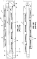
- an enlarged partially shown front elevation view of a pagewidth ink jet printhead 48 is shown of the type that is assembled from sideshooter printhead subunits 10A abutted end-to-end.
- the length is the width of a page or about 8.5 inches (21.6 cm) to 11 inches (28 cm) and the front face height W of the printhead and ink supplying manifold is about 0.50 to 1.0 inch (1.25 to 2.5 cm).
- Schematically illustrated heating elements 20 are shown in each channel 12 through nozzles 14.
- a very small v-groove 59 is optionally anisotropically etched in the surface of the heater plate wafer parallel to and on opposing sides of each set of heating elements, so that the slightly slanted dicing used to produce slanted walls 49 do not cut through the surface 50 containing the heating elements and supporting electrodes and circuitry (not shown).
- the confronting walls 49 of the heater plate 16A were preferably done with a slightly slanted dicing blade to enable the close tolerance abutting of the printhead subunits 10A.
- the oppositely sloping walls 49 produce gaps 53 because the bottom surface of the heater plates 16A are smaller than the top surfaces 50 when the dicing cut is made by slanted dicing blades which are slanted in equal but opposite directions.
- the gaps 53 between the heater plates 16A specifically generated by slanted kerfs that produce sloping or slanted walls 49 may be optionally filled (not shown) with a flowable epoxy or other suitable adhesive.
- the pagewidth printhead 48 may be further stabilized and strengthened by assembly of the printhead subunits 10A on a flat structural member 38.
- Assembly of the pagewidth printhead 48 is complete when an elongated hollow manifold 37 having outlets 34, each aligned with inlets 25 of the printhead subunits 10A.
- Gaskets 35 are sealed to the manifold 37 by a suitable adhesive. The gasket sealingly surrounds the printhead subunit inlets and outlets of the manifold and prevents the ink supplied to the printhead subunits via the manifold from leaking at the interface therebetween.
- U.S. Patent 4,935,750 to Hawkins refer to U.S. Patent 4,935,750 to Hawkins.
- the X, Y, Z coordinates are also shown for this figure; thus, the droplets are ejected from the plane of the sheet containing Figure 5 and in a direction normal thereto and in a direction towards the viewer.
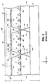
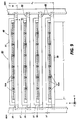
- a pagewidth thermal ink jet printhead 60 in accordance with the present invention is shown, using roofshooter-type printhead subunits 26A.
- the printhead subunits each similar in construction to that depicted in Figure 2, are mounted on edge 67 of structural bar 62 in two rows in an offset staggered manner.
- Each printhead subunit inlet is aligned with openings 65 in bar 62 which place the printhead subunit reservoirs 30 (see Figure 2) into communication with ink supply passageway 64 formed in the bar adjacent the bar edge 67.
- Flexible cables 46 with signal lines 43 therein are mounted on surface 68 of the structural bar 62 and connected to electrodes 21 ( Figure 2) of the printhead subunits by means such as wire bonding (not shown).
- Mounting flanges 66 are attached to each end of the structural bar to provide means for mounting the pagewidth printhead in a printer.
- Each printhead subunit 26A contains two rows of nozzles offset from one another and a cross-sectional view through one nozzle is depicted in Figure 2.
- the structural bar comprises two parts, the main part has a groove 64 milled through one edge thereof and the part is cover 63 which is bonded over the groove and which contains openings 65 therethrough.
- the length of the pagewidth bar is depicted by dimension L which is at least the distance across the width of the recording medium to be printed in the printer printing zone.
- the width of the structural bar is dimensioned to accommodate two printhead subunits and is depicted by the dimension W.
- a thickness or depth of the bar is shown as dimension T.
- An external ink supply (not shown) is located in a spaced location from the pagewidth printhead and provides ink to the passageway 64 in the structural bar by hoses (not shown). Ends of the hose are sealingly attached to the passageway 64 by well known coupling means.
- Figures 3A and 3B show staggered subunit pagewidth print bars using sideshooter printheads
- Figure 6 shows a staggered subunit pagewidth print bar using roofshooter printheads.
- the pagewidth printheads of Figures 3A and 3B use the staggered offset configuration of sideshooter printhead subunit
- the pagewidth printhead of Figure 5 uses pagewidth printhead subunits in an end-to-end abutment arrangement.
- the pagewidth print bar of Figure 6 uses alternating staggered roofshooter printhead subunits in which each subunit has two arrays of staggered nozzles, one on each side of the ink reservoir or feed slot in the heater plate, although a single row of nozzles could be used as shown in Figure 2 and disclosed in U.S. 4,789,425 to Drake et al.
- the use of two staggered rows of roofshooter printhead subunits avoids the technical issues associated with abutting collinear subunits as shown in Figure 5, while preserving the adjacent nozzle distance across the pagewidth printhead.
- the array of subunits can also consist of a single row of abutted subunits, such as those described in U.S.
- roofshooter printheads can be aligned without the significant issues of silicon chip thickness variation or warpage of the structural substrate bar on which they are attached.
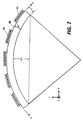
- FIG. 7 shows the problem for a pagewidth sideshooter architecture. Because the side of the bar with the bonded printheads will be at a higher temperature than the opposite side, thermal expansion of the warmer side will cause a bow in the bar. Figure 7 gives a mechanical analysis of this situation. Assuming representative material constraints and dimensions, there is a bow in an eleven inch print bar corresponding to twelve micrometers for each degree centigrade gradient from the top to the bottom of the structural bar, even for an extremely low expansion material such as graphite. Furthermore, this bow affects spot placement in the critical Y direction for a sideshooter.
- the critical dimension is the bar thickness t, which has a cubed relationship relative to the print bar stiffness (that is, warp resistance).
- Force F ⁇ T AE
- ⁇ the constant of thermal expansion
- A cross-sectional area
- ⁇ T the thermal gradient
- E the modulus of elasticity
- t the bar thickness.
- Bending moment M Ft/2
- radius of curvature R EI/M, where I is the moment of inertia which equals thickness of the structural bar t ⁇ the height cubed ⁇ 12.
- the constant of thermal expansion for graphite is equal to 2.5 cm/cm/°C.
- the modulus of elasticity for graphite is equal to 1.5 ⁇ 106psi.
- the pagewidth roofshooter print bar does not require a dedicated ink manifold, since it can feed ink from a reservoir internal of the print bar substrate up through the slot in the silicon heater plate. This not only saves the cost of a manifold and the critical step of printhead to manifold ink sealing, but also allows the printhead and print bar substrate to transfer their heat to the ink which then gets expelled during printing. Thus, the pagewidth roofshooter print bar would have an advantage with respect to thermal management.
- a pagewidth thermal ink jet print bar using roofshooter style printhead subunits enables the use of a print bar substrate having dimensions to minimize the Y axis dimensional tolerances and to provide a larger dimension in the Z axis which confers stiffness and a warp resistance to the print bar.
- a print bar substrate for a roofshooter pagewidth printhead may incorporate the ink distribution system internally, thus eliminating additional ink distribution components.
- this design is thermally advantaged in that the heat from the silicon subunits is transferred to the structural substrate and the ink, where it can more readily leave the ink printing system.
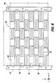
- FIG. 8 A front view of a multi-colored thermal ink jet printhead is shown in Figure 8 utilizing roofshooter-type pagewidth printheads of the type shown in Figure 6.
- the pagewidth printheads may be stacked one on top of the other spaced only by the flexible electrodes, which have a thickness of about 0.1 to 0.2 cm, thus presenting a printing area defined by the length of the pagewidth printhead and the distance defined by the thickness of four structural bars shown in Figure 8 as L and P1, respectively.
- L is between 8.5 inches (21.6 cm) and 11 inches (28 cm)
- W ( Figure 6) is between 0.25 inches (0.64 cm) and 0.5 inches (1.3 cm), so that P1 is between about 1.5 inches (3.8 cm) to 2.25 inches (5.7 cm).
- FIG. 9 A similar front view of a multi-color pagewidth printer using sideshooter printhead subunits is shown in Figure 9.
- Each of the pagewidth printheads uses the end-to-end abutment of printhead subunits, as shown in Figure 5.
- the printing area is defined by the length L of the printing region of the pagewidth printheads and the height of four printheads with ink supplying manifolds 37 for each of the printheads so that the distance P2 of the stacked pagewidth printheads is about 3 inches (7.6 cm) to 4 inches (10 cm) which is greater than that of the roofshooter type print bar.
- any Y distance for a printing zone greater than 2.5 inches for the printing zone is considered detrimental for it permits the wet ink too much time to wick into the paper before a means for drying can be applied, thereby allowing the paper to cockle or wrinkle.
- a sideshooter type pagewidth printhead using abutted subunits as shown in Figure 5 was used in Figure 9, substantially the same or larger printing zone would be required for a multicolor ink jet printer using a plurality of the pagewidth printheads depicted in Figures 3A and 3B. Therefore, the same unsatisfactory color printing would be achieved as with the printhead configuration shown in Figure 9.
- the printhead illustrated in Figure 6 and described above has a minimum dimension in the direction of the movement of the recording medium relative to the printhead. In addition, it has a comparatively large dimension in the direction perpendicular to both the recording medium and printhead in order to confer stiffness and warp resistance to the printhead.
- the print bar internally incorporates the ink distribution system, thereby eliminating additional ink distribution components and resulting in the ability to more closely space pagewidth printheads for multi-color printing.
Abstract
Description
- This invention relates to thermal ink jet printing on demand, and more particularly to pagewidth thermal ink jet printheads.
- There are two general configurations for thermal, drop-on-demand, ink jet printheads. In one configuration, droplets are propelled from nozzles in a direction parallel to the flow of ink in ink channels and parallel to the surface of the bubble-generating heating elements of the printhead, such as, for example, the printhead configuration disclosed in U.S. Reissue Patent RE 32,572 to Hawkins et al. and schematically shown in Figure 1. This configuration is sometimes referred to as an edge or side shooter. The other thermal ink jet configuration propels droplets from nozzles in a direction normal to the surface of the bubble-generating heating elements such as, for example, the printhead disclosed in U.S. Patent number 4,568,953 to Aoki et al. This latter configuration is sometimes referred as a roofshooter and is schematically illustrated in Figure 2. It can be seen that a fundamental difference lies in the direction of droplet ejection. The sideshooter configuration ejects droplets in the plane of the substrate having the heating elements, while the roofshooter ejects droplets out of the plane of the substrate having the heating elements and in a direction normal thereto.
- U.S. Reissue Patent number RE 32,572 to Hawkins et al. discloses a sideshooter configuration for a thermal ink jet printhead and several fabricating processes therefor. Each printhead is composed of two parts aligned and bonded together. One part is a substantially flat substrate which contains on the surface thereof a linear array of heating elements and addressing electrodes, and the second part is a substrate having at least one recess anisotropically etched therein to serve as an ink supply manifold when the two parts are bonded together. A linear array of parallel grooves is also formed in the second part so that one end of each of the grooves communicates with the manifold recess and the other end is open for use as an ink droplet expelling nozzle. Many printheads can be made simultaneously by producing a plurality of sets of heating element arrays with their addressing electrodes on a silicon wafer. A corresponding plurality of sets of channels and associated manifolds are produced in a second silicon wafer. The two wafers are aligned and bonded together and then diced into many separate printheads. The printheads may be used in carriage-type printers for printing swaths of information and then stepping the recording medium a distance of one swath and continuing to print adjacent swaths of information until a full page of information is printed. Alternatively, the printheads may be considered as subunits of a pagewidth printhead and arranged on a structural image bar for pagewidth printing. In pagewidth printing, the printheads may be assembled by abutting a plurality of the printhead subunits end-to-end on the image bar or staggering them on two separate image bars or on opposite sides of the same image bar.
- U.S. Patent number 4,568,953 to Aoki et al. discloses a thermal ink jet printhead in which the droplets are ejected on demand through nozzles aligned above and parallel to the heating elements, so that the droplet trajectories are normal to the heating elements. In order to prevent nozzle clogging, the ink is circulated through the printhead and internal passageways having cross-sectional flow areas larger than the nozzles. This enables particulate matter larger than the nozzles to pass and be swept away by the circulating ink entering and leaving the printhead through inlet and outlet tubes.
- U.S. Patent number 4,789,425 to Drake et al. discloses a roofshooter-type thermal ink jet printhead, wherein each printhead comprises a silicon heater plate and a fluid directing structural member. The heater plate has a linear array of heating elements, associated addressing electrodes, and an elongated ink-filled hole parallel with the heating element array. The structural member contains at least one recessed cavity, a plurality of nozzles, and a plurality of parallel walls within the recessed cavity which define individual ink channels for directing the ink to the nozzles. The recessed cavity and fill hole are in communication with each other and form the ink reservoir within the printhead. The ink holding capacity of the fill hole is larger than that of the recessed cavity. The fill hole is precisely formed and positioned within the heater plate by anisotropic etching. The structural member may be fabricated either from two layers of photoresist, a two-stage flat nickel electroform, or a single photoresist layer and a single stage flat nickel electroform.
- U.S. Patent number 4,829,324 to Drake et al. discloses a large array ink jet printhead having two basic parts, one containing an array of heating elements and addressing electrodes on the surface thereof, and the other containing the liquid ink handling system. At least the part containing the ink handling system is silicon and is assembled from generally identical subunits aligned and bonded side-by-side on the part surface having the heating element array. In one embodiment a plurality of channel plate subunits is anisotropically etched in a silicon wafer and a plurality of heating element subunits is formed on another silicon wafer. The heating element wafer is also anisotropically etched with elongated slots. The wafers are aligned and bonded together, then diced into complete printhead subunits which have abutting side surfaces that are {111} planes for accurate side-by-side assembly.
- U.S. Patent number 4,851,371 to Fisher et al. and U.S. Patent number 4,935,750 to Hawkins disclose a cost effective method of fabricating a large array or pagewidth silicon device having high resolution. The pagewidth device is assembled by abutting silicon device subunits such as image sensors or thermal ink jet printheads. For printheads, the subunits are fully functional small printheads comprising an ink flow directing channel plate and a heating element plate which are bonded together. A plurality of individual printhead subunits is obtained by dicing aligned and bonded channel wafers and heating element wafers. The abutting edges of the printhead subunits are diced in such a manner that the resulting kerfs have vertical to inwardly directed sides which enable high tolerance linear abutment of adjacent subunits. U.S. Patent 4,935,750 discloses how a pagewidth printhead may be further stabilized and strengthened by assembly of printhead subunits on a flat structural member. Assembly of the pagewidth printhead is complete when an elongated hollow conduit means having a plurality of outlets is mounted over the subunits with each outlet aligned with a one of the inlets of the printhead subunits. Gaskets are sealed to the outlets of the conduit means by, for example, an adhesive earlier screened onto the gasket. The gasket sealingly surrounds the printhead subunit inlet and outlets of the conduit means and prevents the ink supplied to the printhead subunits via the conduit means from leaking at the interface therebetween.
- U.S. Patent number 4,985,710 to Drake et al. discloses a "roofshooter" pagewidth printhead for use in a thermal ink jet printing device fabricated from a plurality of subunits, each being produced by bonding a heater substrate, having an architecture including an array of heater elements and an etched ink feed slot, to a secondary substrate having a series of spaced feed hole openings to form a combined substrate in which the series of spaced feed hole openings communicates with the ink feed slot, and dicing the combined substrates through the ink feed slot to form a subunit. An array of butted subunits having a length equal to one pagewidth is formed by butting one of the subunits against an adjacent subunit. The array of butted subunits is bonded to a pagewidth support substrate. The secondary substrate provides an integral support structure for maintaining the alignment of the heater plate which, if diced through the feed hole without the secondary substrate, would separate into individual pieces, thereby complicating the alignment and assembly process.
- It is the object of the present invention to provide an improved pagewidth thermal ink jet printhead.
- According to the present invention, a pagewidth thermal ink jet printhead for an ink jet printer is assembled from fully functional roofshooter-type printhead subunits which are fixedly mounted on the surface of one side of a structural bar. A passageway is formed in the bar and adjacent the bar side surface containing the printhead subunits with openings provided between the passageway and the ink inlets of the printhead subunits mounted thereon, so that ink supplied to the passageway in the bar will maintain the individual subunits full of ink.
- For color printing, wherein a plurality of pagewidth printheads in accordance with the invention are used, the size of the printing zone can be minimized because the roofshooter printhead subunits are mounted on one edge of the structural bar and may be stacked one on top of the other without need to provide space for the printhead subunits and/or ink supply manifolds or lines. Advantageously, the structural bar thickness enables the bar to be massive enough to prevent warping because of printhead operating temperatures.
- The present invention further provides a pagewidth, thermal ink jet printhead for use in an ink jet printer and of type assembled from a plurality of fully functional printhead subunits, each subunit having an array of droplet emitting nozzles, so that when the printhead is fixedly mounted in the printer, the nozzles confront a path through which a recording medium is moved to define a printing zone having the length of at least the width of a page, the printhead comprising:
a structural bar having an edge surface between end surfaces, a length at least equal to that of the printing zone, and a cross-sectional area defined by a predetermined width and thickness of the bar, so that the edge surface of the bar has a surface area defined by the bar length and width, the edge surface confronting the recording medium path when it is mounted in the printer;
a passageway being provided within the bar and being adjacently spaced a predetermined distance from the bar edge surface;
a plurality of openings penetrating the adjacent edge surface and communicating with the passageway;
a plurality of roofshooter type printhead subunits being mounted on the bar edge surface, each subunit having an ink inlet aligned with a respective one of the openings in said bar edge surface and having a plurality of heating elements, each of which is aligned with a respective one of the subunit nozzles for ejection of ink droplets in a direction normal to the heating elements and towards the recording medium path;
means for fixedly mounting the structural bar within the printer, so that the subunits confront the recording medium and are spaced predetermined distance therefrom;
means for providing ink to the bar passageway from an ink supply; and
means for selectively applying electrical signals to the heating elements of the subunits, the signals representing digitized data for the drop-on-demand ejection of ink droplets by the temporary vaporization of ink as a result of the application of the electrical signals, whereby the structural bar thickness is sufficient to provide enough mass for the bar to prevent its warping as a result of the operating temperature of the pagewidth printhead. - By way of example only, embodiments of the invention will be described with reference to the accompanying drawings, in which:
- Figure 1 is a schematic cross-sectional view of a typical prior art sideshooter-type thermal ink jet printhead.
- Figure 2 is a schematic cross-sectional view of a typical prior art roofshooter-type thermal ink jet printhead.
- Figure 3A is a front view of a typical prior art pagewidth printhead formed by staggered sideshooter printhead subunits on two separate structural bars.
- Figure 3B is a front view of a typical prior art pagewidth printhead formed by sideshooter printhead subunits in a staggered array on opposite sides of a single structural bar.
- Figure 4 is a partial isometric view of the prior art pagewidth printhead shown in Figure 3A.
- Figure 5 is an enlarged partially shown front view of a typical prior art pagewidth printhead formed from the abutment of smaller sideshooter printhead subunits produced by the abutment of the subunits on a single structural bar.
- Figure 6 is a partially shown isometric view of a pagewidth printhead in accordance with the present invention, formed by staggered roofshooter printhead subunits on a single structural bar.
- Figure 7 schematically shows the warpage of the structural bar used in Figure 3A.
- Figure 8 is a front view of a multi-color pagewidth thermal ink jet printhead constructed from a plurality of the printheads shown in Figure 6.
- Figure 9 is a front view of a multi-color pagewidth printhead formed from a plurality of pagewidth printheads shown in Figure 5.
- In Figure 1, a typical sideshooter or edgeshooter-type thermal
ink jet printhead 10 is schematically shown in cross-sectional view with the capillary-filledchannel 12 terminating with anozzle 14 at the edge orside 13 of the printhead. The other end of the channel communicates withreservoir 17 which is anisotropically etched insilicon channel plate 11. Concurrently etched with the reservoir, or in a separate etching step, thechannels 12 are etched inchannel plate 11, as disclosed in U.S. Reissue 32,572 to Hawkins et al. and U.S. Patent 4,935,750 to Hawkins.Heater plate 16 contains theheating elements 20 and passivated addressingelectrodes 21 and common return 22 (passivation layer not shown) over whichthick film layer 23 is laminated and patterned to provide individual recesses over each heating element to form pits 24. Thereservoirs 17 are formed by through etches which provideinlet 25 for entrance of theink 32 throughfilter 18 which is placed over the inlet. As is well known in the art, an electric pulse applied to the heating element momentarily vaporizes the ink andforms bubble 19 which expelsdroplet 15 fromnozzle 14. The ink in the channels are supplied by capillary action fromreservoir 17 as shown byarrow 31. - A typical roofshooter-type thermal ink jet printhead is shown in Figure 2. In this configuration, the
silicon heater plate 27 has a reservoir or feedslot 30 etched therethrough. Theinlet 25 is covered byfilter 18. An array ofheating elements 20 are patterned onheater plate surface 33 near the open bottom ofreservoir 30. The heating elements are selectively addressed via passivated addressingelectrodes 21 and common return 22 (passivated layer not shown). Aflow directing layer 29 is patterned to form flow paths for the ink from the reservoir to a location above the heating elements as shown byarrow 31. Anozzle plate 28 containingnozzles 14 is aligned and bonded to flow directinglayer 29 so that the nozzles are directly above the heating elements. Electric signals applied to the heating element temporarily vaporize the ink and form droplet ejecting bubbles 19 which ejectdroplets 15 in a direction normal to the heating element. - Figure 3A depicts one prior art embodiment of a pagewidth thermal ink jet printhead wherein the fully functional sideshooter printhead subunits are mounted on
structural bars 38 in an equally spaced manner. The structural bars withsideshooter printheads 10 similar to those shown in Figure 1 are fastened together bybar connectors 39 having mountingflanges 40. The printheads on each structural bar are supplied with ink frommanifold 37 which has openings (not shown) aligned and sealed with the inlets of the printhead subunits. The bar connectors provide the appropriate spacing between bars to provide clearance for the ink manifolds as well as the printhead subunits. The structural bars and connectors are fixedly attached to each other by, for example,bolts 41. The printhead subunits on one of the structural bars are offset from the printhead subunits of the other structural bar to provide pagewidth coverage by the droplets ejected from the nozzles from all of the printhead subunits. To aid in the understanding of the orientation of the pagewidth printhead, the X, Y and Z coordinates are shown in Figure 3A, with the Z direction being the direction the droplets travel from the printhead nozzles to the recording medium. The X direction is in a plane parallel to the recording medium, and the Y direction indicates the direction of movement of the recording medium past the pagewidth printhead. Thus, in this view, the droplets would travel from the nozzles at the plane of the paper in a direction perpendicular therefrom towards the viewer. An alternate prior art pagewidth printhead utilizing sideshooter printhead subunits is shown in Figure 3B, where a singlestructural bar 38 is used with mountingbar flanges 40 on either edge and with the sideshooter thermal ink jet printhead subunits mounted in a staggered fashion on opposite sides thereof. The printhead subunits on each side of the bar have anink manifold 37 with openings (not shown) aligned and sealed with the inlets of the printhead subunits to prevent ink leakage therefrom. - Referring to Figure 4, a portion of the pagewidth printhead of Figure 3A is shown in isometric view with the
ink supplying manifolds 37 partially shown in dashed line. The X, Y and Z coordinates show the orientation of theprinthead subunits 10 relative to the recording medium (not shown). In this figure, the subunits are shown with thesignal supplying lines 43 attached to theprinthead electrodes 21 via wire bonds 42. - An alternate embodiment of a prior art pagewidth printhead is shown in Figure 5. In this configuration, an enlarged partially shown front elevation view of a pagewidth
ink jet printhead 48 is shown of the type that is assembled fromsideshooter printhead subunits 10A abutted end-to-end. The length is the width of a page or about 8.5 inches (21.6 cm) to 11 inches (28 cm) and the front face height W of the printhead and ink supplying manifold is about 0.50 to 1.0 inch (1.25 to 2.5 cm). Schematically illustratedheating elements 20 are shown in eachchannel 12 throughnozzles 14. In this pagewidth embodiment, a very small v-groove 59 is optionally anisotropically etched in the surface of the heater plate wafer parallel to and on opposing sides of each set of heating elements, so that the slightly slanted dicing used to produce slantedwalls 49 do not cut through thesurface 50 containing the heating elements and supporting electrodes and circuitry (not shown). This eliminates all micro-cracking because the dicing blade only cuts outside of the {111} plane of the small v-groove 59. The confrontingwalls 49 of theheater plate 16A were preferably done with a slightly slanted dicing blade to enable the close tolerance abutting of theprinthead subunits 10A. Theoppositely sloping walls 49produce gaps 53 because the bottom surface of theheater plates 16A are smaller than thetop surfaces 50 when the dicing cut is made by slanted dicing blades which are slanted in equal but opposite directions. To strengthen thepagewidth printhead 48, thegaps 53 between theheater plates 16A specifically generated by slanted kerfs that produce sloping or slantedwalls 49 may be optionally filled (not shown) with a flowable epoxy or other suitable adhesive. Thepagewidth printhead 48 may be further stabilized and strengthened by assembly of theprinthead subunits 10A on a flatstructural member 38. Assembly of thepagewidth printhead 48 is complete when an elongatedhollow manifold 37 havingoutlets 34, each aligned withinlets 25 of theprinthead subunits 10A.Gaskets 35 are sealed to the manifold 37 by a suitable adhesive. The gasket sealingly surrounds the printhead subunit inlets and outlets of the manifold and prevents the ink supplied to the printhead subunits via the manifold from leaking at the interface therebetween. For a more detailed description of this prior art pagewidth printhead, refer to U.S. Patent 4,935,750 to Hawkins. The X, Y, Z coordinates are also shown for this figure; thus, the droplets are ejected from the plane of the sheet containing Figure 5 and in a direction normal thereto and in a direction towards the viewer. - Referring to Figure 6, a pagewidth thermal
ink jet printhead 60 in accordance with the present invention is shown, using roofshooter-type printhead subunits 26A. The printhead subunits, each similar in construction to that depicted in Figure 2, are mounted onedge 67 ofstructural bar 62 in two rows in an offset staggered manner. Each printhead subunit inlet is aligned withopenings 65 inbar 62 which place the printhead subunit reservoirs 30 (see Figure 2) into communication withink supply passageway 64 formed in the bar adjacent thebar edge 67.Flexible cables 46 withsignal lines 43 therein are mounted on surface 68 of thestructural bar 62 and connected to electrodes 21 (Figure 2) of the printhead subunits by means such as wire bonding (not shown). Mountingflanges 66 are attached to each end of the structural bar to provide means for mounting the pagewidth printhead in a printer. Eachprinthead subunit 26A contains two rows of nozzles offset from one another and a cross-sectional view through one nozzle is depicted in Figure 2. For ease in providing a passageway for the ink, the structural bar comprises two parts, the main part has agroove 64 milled through one edge thereof and the part iscover 63 which is bonded over the groove and which containsopenings 65 therethrough. The length of the pagewidth bar is depicted by dimension L which is at least the distance across the width of the recording medium to be printed in the printer printing zone. The width of the structural bar is dimensioned to accommodate two printhead subunits and is depicted by the dimension W. A thickness or depth of the bar is shown as dimension T. An external ink supply (not shown) is located in a spaced location from the pagewidth printhead and provides ink to thepassageway 64 in the structural bar by hoses (not shown). Ends of the hose are sealingly attached to thepassageway 64 by well known coupling means. - As already mentioned, there are two fundamental printhead architectures for thermal ink jet printheads. One is the edgeshooter or sideshooter printhead shown in Figure 1. The other is the roofshooter printhead shown in Figure 2. It can be seen that a fundamental difference lies in the direction of drop ejection. In the sideshooter configuration, droplets are ejected in a plane parallel to the heating element surfaces on the heater plate while in the roofshooter configuration, the droplets are ejected in a direction normal to the surface of the heating element.
- In the construction of a pagewidth array of thermal ink jet printhead subunits to make a pagewidth thermal ink jet print bar, there are significant differences in the print bar architectures, depending upon which printhead subunit architecture is used. Figures 3A and 3B show staggered subunit pagewidth print bars using sideshooter printheads, while Figure 6 shows a staggered subunit pagewidth print bar using roofshooter printheads. The pagewidth printheads of Figures 3A and 3B use the staggered offset configuration of sideshooter printhead subunit, while the pagewidth printhead of Figure 5 uses pagewidth printhead subunits in an end-to-end abutment arrangement.
- The pagewidth print bar of Figure 6 uses alternating staggered roofshooter printhead subunits in which each subunit has two arrays of staggered nozzles, one on each side of the ink reservoir or feed slot in the heater plate, although a single row of nozzles could be used as shown in Figure 2 and disclosed in U.S. 4,789,425 to Drake et al. The use of two staggered rows of roofshooter printhead subunits avoids the technical issues associated with abutting collinear subunits as shown in Figure 5, while preserving the adjacent nozzle distance across the pagewidth printhead. However, the array of subunits can also consist of a single row of abutted subunits, such as those described in U.S. 4,985,710 to Drake et al. While technically more difficult because of the required precision dicing, such a collinear array has the advantage of consuming less space in the Y or paper path direction. As discussed above with reference to Figure 2, the roofshooter printhead subunits are fed with ink via a reservoir or slot in the print bar mounting substrate. The seal between the heater plate of the subunit and the substrate can simply be a printhead bonding adhesive normally used to attach printhead subunits to a substrate. This seal has no precision tolerances and uses commercial techniques and materials.
- In the process of precision placement of the printhead subunits, there is a significant difference in the roofshooter and sideshooter pagewidth print bar architectures. Close tolerances are critical in the X and Y axis for spot placement. The X and Y axis are in the plane of the printhead for roofshooters as seen in Figure 6, while, for the sideshooter, the X and Z axis are in the plane of the printhead but the Y axis is out of the plane of the printhead. The importance of this is twofold. First, roofshooter printheads can be aligned without the significant issues of silicon chip thickness variation or warpage of the structural substrate bar on which they are attached. These two dimensional variations effect the Z axis dimension which is much less critical for spot placement. For the sideshooter configuration, these two issues significantly effect the critical Y axis dimension, introducing adjacent pixel spot placement errors. For example, because of printhead subunit thickness variation from wafer to wafer (normally ± 13 micrometers), sideshooter printhead subunits for a given print bar may need to be taken from the same wafer to ensure thickness uniformity, while roofshooter die subunits can be taken from any wafer because the thickness variation occurs in the non-critical Z axis. Secondly, aligning printhead subunits in their natural plane, that is the plane of the wafer, as is done for roofshooter printheads, is already commercially done for a number full width arrays of silicon transducer technologies, therefor off-the-shelf commercial equipment exists for such alignment.
- Another advantage of the pagewidth thermal ink jet roofshooter print bar architecture lies in its stability to thermal excursions. Figure 7 shows the problem for a pagewidth sideshooter architecture. Because the side of the bar with the bonded printheads will be at a higher temperature than the opposite side, thermal expansion of the warmer side will cause a bow in the bar. Figure 7 gives a mechanical analysis of this situation. Assuming representative material constraints and dimensions, there is a bow in an eleven inch print bar corresponding to twelve micrometers for each degree centigrade gradient from the top to the bottom of the structural bar, even for an extremely low expansion material such as graphite. Furthermore, this bow affects spot placement in the critical Y direction for a sideshooter. As can be seen from Figure 7, the critical dimension is the bar thickness t, which has a cubed relationship relative to the print bar stiffness (that is, warp resistance). Force F = αΔT AE where α = the constant of thermal expansion, A = cross-sectional area, ΔT = the thermal gradient, E = the modulus of elasticity, t = the bar thickness. Bending moment M = Ft/2, and radius of curvature R = EI/M, where I is the moment of inertia which equals thickness of the structural bar t × the height cubed ÷ 12. If, for example, the structural bar is graphite for a ΔT = 1°C, thickness = .25 inches and the depth = 2 inches, the constant of thermal expansion for graphite is equal to 2.5 cm/cm/°C. The modulus of elasticity for graphite is equal to 1.5 × 10⁶psi. The force equals 2.5 pounds, the radius of curvature = 24,000 inches and this results in a bow or change in the Y direction of 12 micrometers per degree centigrade.
- For the pagewidth printhead using roofshooter printhead subunits shown in Figure 6, it can be seen that the direction of thermally induced structural bar warp would be in the less critical Z axis direction and that the critical dimension T can be made very large. As an example of typical values, T might be .25 inches for a sideshooter and might be 2.5 inches for a roofshooter print bar. One reason the T dimension can be large for the roofshooter print bar is because it does not consume paper path space. The effect on the mechanical stability of the print bars would seem to be 1,000 times more rigid than the sideshooter print bar. In terms of ink distribution systems, the pagewidth roofshooter print bar does not require a dedicated ink manifold, since it can feed ink from a reservoir internal of the print bar substrate up through the slot in the silicon heater plate. This not only saves the cost of a manifold and the critical step of printhead to manifold ink sealing, but also allows the printhead and print bar substrate to transfer their heat to the ink which then gets expelled during printing. Thus, the pagewidth roofshooter print bar would have an advantage with respect to thermal management. Also, a pagewidth thermal ink jet print bar using roofshooter style printhead subunits enables the use of a print bar substrate having dimensions to minimize the Y axis dimensional tolerances and to provide a larger dimension in the Z axis which confers stiffness and a warp resistance to the print bar. A print bar substrate for a roofshooter pagewidth printhead may incorporate the ink distribution system internally, thus eliminating additional ink distribution components. In addition, this design is thermally advantaged in that the heat from the silicon subunits is transferred to the structural substrate and the ink, where it can more readily leave the ink printing system.
- In multi-color ink jet printing systems, several pagewidth printheads must be used, one for each color. Generally, four printheads are used, one for black and one each for magenta, yellow and cyan. To prevent the ink from wicking into the recording medium, usually paper, it is important to minimize the area of the printing zone so that the ink can quickly be dried. A front view of a multi-colored thermal ink jet printhead is shown in Figure 8 utilizing roofshooter-type pagewidth printheads of the type shown in Figure 6. Because the printhead subunits are bonded to the edge of the structural bar facing the Z direction, the pagewidth printheads may be stacked one on top of the other spaced only by the flexible electrodes, which have a thickness of about 0.1 to 0.2 cm, thus presenting a printing area defined by the length of the pagewidth printhead and the distance defined by the thickness of four structural bars shown in Figure 8 as L and P₁, respectively. In the preferred embodiment, L is between 8.5 inches (21.6 cm) and 11 inches (28 cm) and W (Figure 6) is between 0.25 inches (0.64 cm) and 0.5 inches (1.3 cm), so that P₁ is between about 1.5 inches (3.8 cm) to 2.25 inches (5.7 cm). A similar front view of a multi-color pagewidth printer using sideshooter printhead subunits is shown in Figure 9. Each of the pagewidth printheads uses the end-to-end abutment of printhead subunits, as shown in Figure 5. The printing area is defined by the length L of the printing region of the pagewidth printheads and the height of four printheads with
ink supplying manifolds 37 for each of the printheads so that the distance P₂ of the stacked pagewidth printheads is about 3 inches (7.6 cm) to 4 inches (10 cm) which is greater than that of the roofshooter type print bar. Any Y distance for a printing zone greater than 2.5 inches for the printing zone is considered detrimental for it permits the wet ink too much time to wick into the paper before a means for drying can be applied, thereby allowing the paper to cockle or wrinkle. Though a sideshooter type pagewidth printhead using abutted subunits as shown in Figure 5 was used in Figure 9, substantially the same or larger printing zone would be required for a multicolor ink jet printer using a plurality of the pagewidth printheads depicted in Figures 3A and 3B. Therefore, the same unsatisfactory color printing would be achieved as with the printhead configuration shown in Figure 9. - The printhead illustrated in Figure 6 and described above has a minimum dimension in the direction of the movement of the recording medium relative to the printhead. In addition, it has a comparatively large dimension in the direction perpendicular to both the recording medium and printhead in order to confer stiffness and warp resistance to the printhead. The print bar internally incorporates the ink distribution system, thereby eliminating additional ink distribution components and resulting in the ability to more closely space pagewidth printheads for multi-color printing.
Claims (6)
- A pagewidth, thermal ink jet printhead for use in an ink jet printer, the printhead comprising:
a structural bar (62) having an edge surface (67) which confronts the recording medium path when the bar is mounted in the printer;
a passageway (64) provided within the bar;
a plurality of openings (65) penetrating the said edge surface and communicating with the passageway;
a plurality of roofshooter-type printhead subunits (26A) mounted on the bar edge surface, each subunit having an ink inlet (25) aligned with a respective one of the openings in said bar edge surface, an array of droplet emitting nozzles (14), and a plurality of heating elements (20), each of which is aligned with a respective one of the subunit nozzles for ejection of ink droplets in a direction normal to the heating elements and to the said edge surface, the nozzles of the plurality of subunits defining a printing zone having the length (L) of at least the width of a page,
means for providing ink to the bar passageway from an ink supply; and
means (46) for selectively applying electrical signals to the heating elements of the subunits, the thickness (T) of the structural bar being sufficient to prevent the bar warping as a result of the operating temperature of the page width printhead. - A pagewidth printhead as claimed in claim 1, wherein the roofshooter printhead subunits are mounted on the edge surface of the bar in two rows in a staggered arrangement.
- A pagewidth printhead as claimed in claim 1 or claim 2, wherein each printhead subunit has two rows of nozzles.
- A pagewidth printhead as claimed in claim 1, wherein the roofshooter printhead subunits are mounted on the edge surface of the bar in a single, abutted collinear row of subunits.
- A pagewidth printhead as claimed in any one of the preceding claims, wherein the structural bar comprises a main part with a groove in a surface thereof and a cover (63) mounted on the said surface of said main part and over the groove therein to form the passageway in said bar, the plurality of openings being in said cover, so that said edge surface of the bar whereon the subunits are mounted is the outer surface of the cover.
- A multicolor printer comprising a plurality of pagewidth printheads each as claimed in any one of the preceding claims, the printheads being stacked with their respective subunits confronting the printing zone of the printer, and a different colored ink supply for each pagewidth printhead.
Applications Claiming Priority (2)
| Application Number | Priority Date | Filing Date | Title |
|---|---|---|---|
| US698206 | 1985-02-04 | ||
| US07/698,206 US5160945A (en) | 1991-05-10 | 1991-05-10 | Pagewidth thermal ink jet printhead |
Publications (3)
| Publication Number | Publication Date |
|---|---|
| EP0512799A2 true EP0512799A2 (en) | 1992-11-11 |
| EP0512799A3 EP0512799A3 (en) | 1993-01-20 |
| EP0512799B1 EP0512799B1 (en) | 1995-08-09 |
Family
ID=24804320
Family Applications (1)
| Application Number | Title | Priority Date | Filing Date |
|---|---|---|---|
| EP92304052A Expired - Lifetime EP0512799B1 (en) | 1991-05-10 | 1992-05-06 | Pagewidth thermal ink jet printhead |
Country Status (4)
| Country | Link |
|---|---|
| US (1) | US5160945A (en) |
| EP (1) | EP0512799B1 (en) |
| JP (1) | JP2752843B2 (en) |
| DE (1) | DE69203934T2 (en) |
Cited By (29)
| Publication number | Priority date | Publication date | Assignee | Title |
|---|---|---|---|---|
| EP0623470A2 (en) * | 1993-05-07 | 1994-11-09 | Canon Kabushiki Kaisha | Method and apparatus for assembling head units, and ink jet output apparatus |
| EP0652107A2 (en) * | 1993-11-10 | 1995-05-10 | OLIVETTI - CANON INDUSTRIALE S.p.A. | Parallel printing device with modular structure and relative process for the production thereof |
| EP0677388A2 (en) * | 1994-04-14 | 1995-10-18 | Hewlett-Packard Company | Ink jet printhead with adress and data bus |
| US5594477A (en) * | 1994-11-30 | 1997-01-14 | Xerox Corporation | Wet wiper and vacuum primer configuration for full-width-array printbar |
| EP0773108A2 (en) * | 1995-11-10 | 1997-05-14 | Seiko Epson Corporation | Ink jet type recording head |
| EP0813968A2 (en) * | 1996-06-19 | 1997-12-29 | Seiko Epson Corporation | Head for printing apparatus |
| EP0824243A2 (en) * | 1996-08-05 | 1998-02-18 | Canon Kabushiki Kaisha | Printing apparatus with registration of line print heads |
| EP0832743A2 (en) * | 1996-09-30 | 1998-04-01 | Canon Kabushiki Kaisha | Ink-jet printer and printing method, auxiliary member, ink-jet head, warp correction method, ink-jet head unit and color-mixture reducing method |
| EP0985536A1 (en) * | 1995-11-10 | 2000-03-15 | Seiko Epson Corporation | Ink jet type recording head |
| WO2000024584A1 (en) * | 1998-10-24 | 2000-05-04 | Xaar Technology Limited | Droplet deposition apparatus |
| US6135586A (en) * | 1995-10-31 | 2000-10-24 | Hewlett-Packard Company | Large area inkjet printhead |
| WO2002044810A1 (en) * | 2000-11-30 | 2002-06-06 | Silverbrook Research Pty Ltd | Data projector with internal printer |
| EP1405722A1 (en) * | 2001-06-20 | 2004-04-07 | Sony Corporation | Liquid discharging device and liquid discharging method |
| US6820966B1 (en) | 1998-10-24 | 2004-11-23 | Xaar Technology Limited | Droplet deposition apparatus |
| AU2004203658B2 (en) * | 1997-07-15 | 2006-05-11 | Google Inc. | A replenishable one time use camera system with recapping mechanism |
| WO2008065222A1 (en) * | 2006-11-28 | 2008-06-05 | Kerajet, S.A. | Self-contained inkjet printing module |
| AU2005203484B2 (en) * | 2000-03-02 | 2008-10-23 | Memjet Technology Limited | Printhead with overlapping arrays of nozzles |
| US8096642B2 (en) | 1997-08-11 | 2012-01-17 | Silverbrook Research Pty Ltd | Inkjet nozzle with paddle layer arranged between first and second wafers |
| US8274665B2 (en) | 1997-07-15 | 2012-09-25 | Silverbrook Research Pty Ltd | Image sensing and printing device |
| US8285137B2 (en) | 1997-07-15 | 2012-10-09 | Silverbrook Research Pty Ltd | Digital camera system for simultaneous printing and magnetic recording |
| US8421869B2 (en) | 1997-07-15 | 2013-04-16 | Google Inc. | Camera system for with velocity sensor and de-blurring processor |
| US8789939B2 (en) | 1998-11-09 | 2014-07-29 | Google Inc. | Print media cartridge with ink supply manifold |
| US8823823B2 (en) | 1997-07-15 | 2014-09-02 | Google Inc. | Portable imaging device with multi-core processor and orientation sensor |
| US8866923B2 (en) | 1999-05-25 | 2014-10-21 | Google Inc. | Modular camera and printer |
| US8896724B2 (en) | 1997-07-15 | 2014-11-25 | Google Inc. | Camera system to facilitate a cascade of imaging effects |
| US8902333B2 (en) | 1997-07-15 | 2014-12-02 | Google Inc. | Image processing method using sensed eye position |
| US8908075B2 (en) | 1997-07-15 | 2014-12-09 | Google Inc. | Image capture and processing integrated circuit for a camera |
| US8936196B2 (en) | 1997-07-15 | 2015-01-20 | Google Inc. | Camera unit incorporating program script scanner |
| EP3112161A4 (en) * | 2014-02-28 | 2018-02-07 | Konica Minolta, Inc. | Inkjet recording device |
Families Citing this family (198)
| Publication number | Priority date | Publication date | Assignee | Title |
|---|---|---|---|---|
| DE4309255A1 (en) * | 1993-03-16 | 1994-09-22 | Francotyp Postalia Gmbh | Modular inkjet print head |
| US5745136A (en) * | 1993-04-16 | 1998-04-28 | Canon Kabushiki Kaishi | Liquid jet head, and liquid jet apparatus therefor |
| US5528272A (en) * | 1993-12-15 | 1996-06-18 | Xerox Corporation | Full width array read or write bars having low induced thermal stress |
| US5659346A (en) * | 1994-03-21 | 1997-08-19 | Spectra, Inc. | Simplified ink jet head |
| US5474032A (en) * | 1995-03-20 | 1995-12-12 | Krietzman; Mark H. | Suspended feline toy and exerciser |
| JP3268937B2 (en) * | 1994-04-14 | 2002-03-25 | キヤノン株式会社 | Substrate for inkjet recording head and head using the same |
| US6130098A (en) * | 1995-09-15 | 2000-10-10 | The Regents Of The University Of Michigan | Moving microdroplets |
| US6057149A (en) * | 1995-09-15 | 2000-05-02 | The University Of Michigan | Microscale devices and reactions in microscale devices |
| US6911183B1 (en) | 1995-09-15 | 2005-06-28 | The Regents Of The University Of Michigan | Moving microdroplets |
| US6048734A (en) * | 1995-09-15 | 2000-04-11 | The Regents Of The University Of Michigan | Thermal microvalves in a fluid flow method |
| US5710582A (en) | 1995-12-07 | 1998-01-20 | Xerox Corporation | Hybrid ink jet printer |
| US5751311A (en) * | 1996-03-29 | 1998-05-12 | Xerox Corporation | Hybrid ink jet printer with alignment of scanning printheads to pagewidth printbar |
| US5808635A (en) * | 1996-05-06 | 1998-09-15 | Xerox Corporation | Multiple die assembly printbar with die spacing less than an active print length |
| US5786829A (en) * | 1996-07-01 | 1998-07-28 | Xerox Corporation | Apparatus and method for cleaning an ink flow path of an ink jet printhead |
| DE69734480T2 (en) | 1996-07-26 | 2006-05-24 | Seiko Epson Corp. | Ink jet type recording head |
| US5939206A (en) * | 1996-08-29 | 1999-08-17 | Xerox Corporation | Stabilized porous, electrically conductive substrates |
| US5801727A (en) * | 1996-11-04 | 1998-09-01 | Xerox Corporation | Apparatus and method for printing device |
| US5719605A (en) * | 1996-11-20 | 1998-02-17 | Lexmark International, Inc. | Large array heater chips for thermal ink jet printheads |
| US6312099B1 (en) * | 1997-01-21 | 2001-11-06 | Eastman Kodak Company | Printing uniformity using printhead segments in pagewidth digital printers |
| US5923347A (en) * | 1997-01-24 | 1999-07-13 | Xerox Corporation | Method and system for cleaning an ink jet printhead |
| US7466341B2 (en) * | 1997-07-15 | 2008-12-16 | Silverbrook Research Pty Ltd | Disposable camera with destructive casing |
| US7832817B2 (en) * | 1997-07-15 | 2010-11-16 | Silverbrook Research Pty Ltd | Recyclable printing device with tamper protection |
| US6857724B2 (en) | 1997-07-15 | 2005-02-22 | Silverbrook Research Pty Ltd | Print assembly for a wide format pagewidth printer |
| US20080309714A1 (en) * | 1997-07-15 | 2008-12-18 | Silverbrook Research Pty Ltd | Printhead integrated circuit with low volume ink chambers |
| US20080316266A1 (en) * | 1997-07-15 | 2008-12-25 | Silverbrook Research Pty Ltd | Printhead integrated circuit with small nozzle apertures |
| US6916082B2 (en) * | 1997-07-15 | 2005-07-12 | Silverbrook Research Pty Ltd | Printing mechanism for a wide format pagewidth inkjet printer |
| US6672706B2 (en) | 1997-07-15 | 2004-01-06 | Silverbrook Research Pty Ltd | Wide format pagewidth inkjet printer |
| US20080316263A1 (en) * | 1997-07-15 | 2008-12-25 | Silverbrook Research Pty Ltd | Printhead integrated circuit with high density array of droplet ejectors |
| US7891767B2 (en) * | 1997-07-15 | 2011-02-22 | Silverbrook Research Pty Ltd | Modular self-capping wide format print assembly |
| US20080309723A1 (en) * | 1997-07-15 | 2008-12-18 | Silverbrook Research Pty Ltd | Printhead integrated circuit with large array of droplet ejectors |
| US6679584B2 (en) | 1997-07-15 | 2004-01-20 | Silverbrook Research Pty Ltd. | High volume pagewidth printing |
| US7011390B2 (en) * | 1997-07-15 | 2006-03-14 | Silverbrook Research Pty Ltd | Printing mechanism having wide format printing zone |
| AUPP654598A0 (en) * | 1998-10-16 | 1998-11-05 | Silverbrook Research Pty Ltd | Micromechanical device and method (ij46h) |
| US20080303851A1 (en) * | 1997-07-15 | 2008-12-11 | Silverbrook Research Pty Ltd | Electro-thermally actuated printer with high media feed speed |
| US6876394B1 (en) * | 1997-07-15 | 2005-04-05 | Silverbrook Research Pty Ltd | Arrangement of ink in a low-cost disposable camera |
| US20080316267A1 (en) * | 1997-07-15 | 2008-12-25 | Silverbrook Research Pty Ltd | Printhead integrated circuit with low power operation |
| US6318849B1 (en) * | 1997-07-15 | 2001-11-20 | Silverbrook Research Pty Ltd | Fluid supply mechanism for multiple fluids to multiple spaced orifices |
| US7044584B2 (en) * | 1997-07-15 | 2006-05-16 | Silverbrook Research Pty Ltd | Wide format pagewidth inkjet printer |
| US20080316265A1 (en) * | 1997-07-15 | 2008-12-25 | Silverbrook Research Pty Ltd | Printhead integrated circuit with high density array of droplet ejectors |
| US20080309724A1 (en) * | 1997-07-15 | 2008-12-18 | Silverbrook Research Pty Ltd | Printhead integrated circuit with small volume droplet ejectors |
| US20080309712A1 (en) * | 1997-07-15 | 2008-12-18 | Silverbrook Research Pty Ltd | Printhead integrated circuit with actuators close to exterior surface |
| US20080309727A1 (en) * | 1997-07-15 | 2008-12-18 | Silverbrook Research Pty Ltd | Printhead integrated circuit with ink supply from back face |
| US7524026B2 (en) * | 1997-07-15 | 2009-04-28 | Silverbrook Research Pty Ltd | Nozzle assembly with heat deflected actuator |
| US7303254B2 (en) * | 1997-07-15 | 2007-12-04 | Silverbrook Research Pty Ltd | Print assembly for a wide format pagewidth printer |
| US7006143B1 (en) * | 1997-07-15 | 2006-02-28 | Silverbrook Research Pty Ltd | Arrangement of print media in a low-cost disposable camera |
| US6738096B1 (en) | 1998-07-10 | 2004-05-18 | Silverbrook Research Pty Ltd | Low-cost disposable camera including print media carrying indication of postage paid |
| SG109967A1 (en) * | 1997-07-15 | 2005-04-28 | Silverbrook Res Pty Ltd | Reusable camera system which authenticates a refill station |
| US7497555B2 (en) * | 1998-07-10 | 2009-03-03 | Silverbrook Research Pty Ltd | Inkjet nozzle assembly with pre-shaped actuator |
| US6557977B1 (en) * | 1997-07-15 | 2003-05-06 | Silverbrook Research Pty Ltd | Shape memory alloy ink jet printing mechanism |
| US20080316264A1 (en) * | 1997-07-15 | 2008-12-25 | Silverbrook Research Pty Ltd | Printhead integrated circuit with nozzles in thin surface layer |
| US20080316268A1 (en) * | 1997-07-15 | 2008-12-25 | Silverbrook Research Pty Ltd | Printhead with low power drive pulses for actuators |
| US7246881B2 (en) | 1997-07-15 | 2007-07-24 | Silverbrook Research Pty Ltd | Printhead assembly arrangement for a wide format pagewidth inkjet printer |
| US20080309713A1 (en) * | 1997-07-15 | 2008-12-18 | Silverbrook Research Pty Ltd | Printhead integrated circuit with low droplet ejection velocity |
| US20080303867A1 (en) * | 1997-07-15 | 2008-12-11 | Silverbrook Research Pty Ltd | Method of forming printhead by removing sacrificial material through nozzle apertures |
| US6158837A (en) * | 1997-09-19 | 2000-12-12 | Xerox Corporation | Printer having print mode for non-qualified marking material |
| US6350013B1 (en) | 1997-10-28 | 2002-02-26 | Hewlett-Packard Company | Carrier positioning for wide-array inkjet printhead assembly |
| US6123410A (en) | 1997-10-28 | 2000-09-26 | Hewlett-Packard Company | Scalable wide-array inkjet printhead and method for fabricating same |
| US6789878B2 (en) | 1997-10-28 | 2004-09-14 | Hewlett-Packard Development Company, L.P. | Fluid manifold for printhead assembly |
| US6250738B1 (en) * | 1997-10-28 | 2001-06-26 | Hewlett-Packard Company | Inkjet printing apparatus with ink manifold |
| EP0914950A3 (en) | 1997-11-06 | 1999-12-08 | Xerox Corporation | An ink jet printhead assembled from partial width array printheads |
| US6234605B1 (en) | 1998-01-08 | 2001-05-22 | Xerox Corporation | Multiple resolution pagewidth ink jet printer including a positionable pagewidth printbear |
| US6151037A (en) * | 1998-01-08 | 2000-11-21 | Zebra Technologies Corporation | Printing apparatus |
| US6089693A (en) * | 1998-01-08 | 2000-07-18 | Xerox Corporation | Pagewidth ink jet printer including multiple pass defective nozzle correction |
| US6820959B1 (en) | 1998-06-03 | 2004-11-23 | Lexmark International, In.C | Ink jet cartridge structure |
| US6164762A (en) * | 1998-06-19 | 2000-12-26 | Lexmark International, Inc. | Heater chip module and process for making same |
| US6204142B1 (en) * | 1998-08-24 | 2001-03-20 | Micron Technology, Inc. | Methods to form electronic devices |
| US7216956B2 (en) * | 1998-10-16 | 2007-05-15 | Silverbrook Research Pty Ltd | Printhead assembly with power and ground connections along single edge |
| EP1121249B1 (en) * | 1998-10-16 | 2007-07-25 | Silverbrook Research Pty. Limited | Process of forming a nozzle for an inkjet printhead |
| US7677686B2 (en) * | 1998-10-16 | 2010-03-16 | Silverbrook Research Pty Ltd | High nozzle density printhead ejecting low drop volumes |
| US7154580B2 (en) * | 1998-11-09 | 2006-12-26 | Silverbrook Research Pty Ltd | Image recordal and generation apparatus |
| AUPP701798A0 (en) | 1998-11-09 | 1998-12-03 | Silverbrook Research Pty Ltd | Image creation method and apparatus (ART75) |
| US6428145B1 (en) | 1998-12-17 | 2002-08-06 | Hewlett-Packard Company | Wide-array inkjet printhead assembly with internal electrical routing system |
| US6341845B1 (en) | 2000-08-25 | 2002-01-29 | Hewlett-Packard Company | Electrical connection for wide-array inkjet printhead assembly with hybrid carrier for printhead dies |
| US6705705B2 (en) | 1998-12-17 | 2004-03-16 | Hewlett-Packard Development Company, L.P. | Substrate for fluid ejection devices |
| US6464333B1 (en) | 1998-12-17 | 2002-10-15 | Hewlett-Packard Company | Inkjet printhead assembly with hybrid carrier for printhead dies |
| US6450614B1 (en) | 1998-12-17 | 2002-09-17 | Hewlett-Packard Company | Printhead die alignment for wide-array inkjet printhead assembly |
| US6286938B1 (en) * | 1999-02-17 | 2001-09-11 | Hitachi, Ltd. | Ink jet recording head and ink jet recording apparatus |
| US6183063B1 (en) | 1999-03-04 | 2001-02-06 | Lexmark International, Inc. | Angled printer cartridge |
| AUPP922299A0 (en) * | 1999-03-16 | 1999-04-15 | Silverbrook Research Pty Ltd | An image creation method and apparatus (macro 01) |
| AU2004201741B2 (en) * | 1999-03-16 | 2005-06-23 | Silverbrook Research Pty Ltd | Wide format printer |
| AU770374B2 (en) * | 1999-03-16 | 2004-02-19 | Memjet Technology Limited | Pagewidth wide format printer |
| AU772083B2 (en) * | 1999-04-22 | 2004-04-08 | Memjet Technology Limited | Page-width printhead |
| US6795215B1 (en) * | 2000-05-23 | 2004-09-21 | Silverbrook Research Pty Ltd | Print engine/controller and printhead interface chip incorporating the engine/controller |
| WO2001002172A1 (en) | 1999-06-30 | 2001-01-11 | Silverbrook Research Pty Ltd | Printhead support structure and assembly |
| EP1157844B1 (en) * | 1999-12-01 | 2008-07-09 | Sony Corporation | Method of driving print head in inkjet printer, and inkjet printer |
| AUPQ455999A0 (en) * | 1999-12-09 | 2000-01-06 | Silverbrook Research Pty Ltd | Memjet four color modular print head packaging |
| AUPQ595700A0 (en) * | 2000-03-02 | 2000-03-23 | Silverbrook Research Pty Ltd | Alignment module for printheads |
| US7322675B2 (en) * | 2000-03-02 | 2008-01-29 | Silverbrook Research Pty Ltd | Mounting for a modular printhead |
| AU2005201838B2 (en) * | 2000-03-06 | 2008-03-06 | Silverbrook Research Pty Ltd | A pagewidth printhead assembly |
| AUPQ605800A0 (en) * | 2000-03-06 | 2000-03-30 | Silverbrook Research Pty Ltd | Printehead assembly |
| US6935023B2 (en) | 2000-03-08 | 2005-08-30 | Hewlett-Packard Development Company, L.P. | Method of forming electrical connection for fluid ejection device |
| AUPQ615800A0 (en) * | 2000-03-10 | 2000-03-30 | Silverbrook Research Pty Ltd | Thermal expansion compensation in printhead assemblies |
| US6482574B1 (en) * | 2000-04-20 | 2002-11-19 | Hewlett-Packard Co. | Droplet plate architecture in ink-jet printheads |
| JP4501222B2 (en) * | 2000-05-12 | 2010-07-14 | ソニー株式会社 | Inkjet printer and head cartridge thereof |
| US6786658B2 (en) * | 2000-05-23 | 2004-09-07 | Silverbrook Research Pty. Ltd. | Printer for accommodating varying page thicknesses |
| US6526658B1 (en) | 2000-05-23 | 2003-03-04 | Silverbrook Research Pty Ltd | Method of manufacture of an ink jet printhead having a moving nozzle with an externally arranged actuator |
| US6652078B2 (en) * | 2000-05-23 | 2003-11-25 | Silverbrook Research Pty Ltd | Ink supply arrangement for a printer |
| EP1289762B1 (en) * | 2000-05-24 | 2005-11-09 | Silverbrook Research Pty. Limited | Paper thickness sensor in a printer |
| US6733112B2 (en) | 2000-08-25 | 2004-05-11 | Hewlett-Packard Development Company | Carrier for printhead assembly including fluid manifold and isolation wells for electrical components |
| US6543880B1 (en) | 2000-08-25 | 2003-04-08 | Hewlett-Packard Company | Inkjet printhead assembly having planarized mounting layer for printhead dies |
| US6612240B1 (en) * | 2000-09-15 | 2003-09-02 | Silverbrook Research Pty Ltd | Drying of an image on print media in a modular commercial printer |
| EP1221372B1 (en) * | 2001-01-05 | 2005-06-08 | Hewlett-Packard Company | Integrated programmable fire pulse generator for inkjet printhead assembly |
| US6585339B2 (en) | 2001-01-05 | 2003-07-01 | Hewlett Packard Co | Module manager for wide-array inkjet printhead assembly |
| US6726298B2 (en) | 2001-02-08 | 2004-04-27 | Hewlett-Packard Development Company, L.P. | Low voltage differential signaling communication in inkjet printhead assembly |
| US6409307B1 (en) | 2001-02-14 | 2002-06-25 | Hewlett-Packard Company | Coplanar mounting of printhead dies for wide-array inkjet printhead assembly |
| US6557976B2 (en) | 2001-02-14 | 2003-05-06 | Hewlett-Packard Development Company, L.P. | Electrical circuit for wide-array inkjet printhead assembly |
| US6394580B1 (en) | 2001-03-20 | 2002-05-28 | Hewlett-Packard Company | Electrical interconnection for wide-array inkjet printhead assembly |
| US6431683B1 (en) | 2001-03-20 | 2002-08-13 | Hewlett-Packard Company | Hybrid carrier for wide-array inkjet printhead assembly |
| AUPR399301A0 (en) * | 2001-03-27 | 2001-04-26 | Silverbrook Research Pty. Ltd. | An apparatus and method(ART106) |
| AUPR399001A0 (en) | 2001-03-27 | 2001-04-26 | Silverbrook Research Pty. Ltd. | An apparatus and method(ART104) |
| US6428141B1 (en) * | 2001-04-23 | 2002-08-06 | Hewlett-Packard Company | Reference datums for inkjet printhead assembly |
| US6471335B1 (en) * | 2001-08-06 | 2002-10-29 | Creo Inc. | Method for mutual spatial registration of inkjet cartridges |
| US6679581B2 (en) | 2001-10-25 | 2004-01-20 | Hewlett-Packard Development Company, L.P. | Surface deformation of carrier for printhead dies |
| US6575559B2 (en) | 2001-10-31 | 2003-06-10 | Hewlett-Packard Development Company, L.P. | Joining of different materials of carrier for fluid ejection devices |
| JP3922004B2 (en) * | 2001-11-30 | 2007-05-30 | ブラザー工業株式会社 | Inkjet printer head |
| US6726300B2 (en) * | 2002-04-29 | 2004-04-27 | Hewlett-Packard Development Company, L.P. | Fire pulses in a fluid ejection device |
| US7164506B2 (en) * | 2002-06-07 | 2007-01-16 | Xerox Corporation | Multi-chip image sensor, on chip apparatus for causing each chip to selectably function in a parallel or serial readout |
| JP3707558B2 (en) | 2002-08-26 | 2005-10-19 | セイコーエプソン株式会社 | Liquid jet head |
| ITTO20020876A1 (en) * | 2002-10-10 | 2004-04-11 | Olivetti I Jet Spa | PARALLEL INK JET PRINTING DEVICE |
| US6814421B2 (en) * | 2002-10-24 | 2004-11-09 | Hewlett-Packard Development Company, L.P. | Printing device and method |
| US6799827B2 (en) * | 2002-10-30 | 2004-10-05 | Hewlett-Packard Development Company, L.P. | Flush process for carrier of printhead assembly |
| US6869165B2 (en) * | 2002-10-30 | 2005-03-22 | Hewlett-Packard Development Company, L.P. | Fluid interconnect for printhead assembly |
| US6942316B2 (en) * | 2002-10-30 | 2005-09-13 | Hewlett-Packard Development Company, L.P. | Fluid delivery for printhead assembly |
| US6869162B2 (en) | 2003-03-27 | 2005-03-22 | Hewlett-Packard Development Company, L.P. | Printing device and method for servicing same |
| US6869166B2 (en) * | 2003-04-09 | 2005-03-22 | Joaquim Brugue | Multi-die fluid ejection apparatus and method |
| US6736488B1 (en) | 2003-05-23 | 2004-05-18 | Hewlett-Packard Development Company, L.P. | Electrical interconnect for printhead assembly |
| US7416295B2 (en) * | 2003-08-06 | 2008-08-26 | Hewlett-Packard Development Company, L.P. | Filter for printhead assembly |
| US7188942B2 (en) * | 2003-08-06 | 2007-03-13 | Hewlett-Packard Development Company, L.P. | Filter for printhead assembly |
| US7422309B2 (en) * | 2003-09-24 | 2008-09-09 | Fujifilm Corporation | Droplet discharging head |
| US7229152B2 (en) * | 2003-10-31 | 2007-06-12 | Hewlett-Packard Development Company, L.P. | Fluid ejection device with insulating feature |
| US7306320B2 (en) * | 2003-11-12 | 2007-12-11 | Silverbrook Research Pty Ltd | High speed digital printer unit |
| US6808249B1 (en) | 2003-12-16 | 2004-10-26 | Fuji Xerox Co., Ltd. | Reduced number of nonbuttable full-width array printbars required in a color printer |
| US7303251B2 (en) * | 2004-01-21 | 2007-12-04 | Silverbrook Research Pty Ltd | Inkjet printer cradle with integrated cartridge engaging mechanism |
| US7097291B2 (en) * | 2004-01-21 | 2006-08-29 | Silverbrook Research Pty Ltd | Inkjet printer cartridge with ink refill port having multiple ink couplings |
| US7287846B2 (en) * | 2004-01-21 | 2007-10-30 | Silverbrook Research Pty Ltd | Inkjet printer cartridge with combined blotter |
| US7425050B2 (en) * | 2004-01-21 | 2008-09-16 | Silverbrook Research Pty Ltd | Method for facilitating maintenance of an inkjet printer having a pagewidth printhead |
| US20050157112A1 (en) | 2004-01-21 | 2005-07-21 | Silverbrook Research Pty Ltd | Inkjet printer cradle with shaped recess for receiving a printer cartridge |
| US7083272B2 (en) * | 2004-01-21 | 2006-08-01 | Silverbrook Research Pty Ltd | Secure method of refilling an inkjet printer cartridge |
| US7360868B2 (en) * | 2004-01-21 | 2008-04-22 | Silverbrook Research Pty Ltd | Inkjet printer cartridge with infrared ink delivery capabilities |
| US7367650B2 (en) | 2004-01-21 | 2008-05-06 | Silverbrook Research Pty Ltd | Printhead chip having low aspect ratio ink supply channels |
| US7303255B2 (en) | 2004-01-21 | 2007-12-04 | Silverbrook Research Pty Ltd | Inkjet printer cartridge with a compressed air port |
| US7364264B2 (en) * | 2004-01-21 | 2008-04-29 | Silverbrook Research Pty Ltd | Inkjet printer cradle with single drive motor performing multiple functions |
| US20050157128A1 (en) * | 2004-01-21 | 2005-07-21 | Silverbrook Research Pty Ltd | Pagewidth inkjet printer cartridge with end electrical connectors |
| US7469989B2 (en) * | 2004-01-21 | 2008-12-30 | Silverbrook Research Pty Ltd | Printhead chip having longitudinal ink supply channels interrupted by transverse bridges |
| US7547092B2 (en) | 2004-01-21 | 2009-06-16 | Silverbrook Research Pty Ltd | Method for facilitating the upgrade of an inkjet printer |
| US20050157125A1 (en) * | 2004-01-21 | 2005-07-21 | Silverbrook Research Pty Ltd | Inkjet printer cartridge with integral shield |
| US7293861B2 (en) * | 2004-01-21 | 2007-11-13 | Silverbrook Research Pty Ltd | Inkjet printer cartridge refill dispenser system with variably positioned outlets |
| US20050157000A1 (en) * | 2004-01-21 | 2005-07-21 | Silverbrook Research Pty Ltd | Inkjet printer cradle with end data and power contacts |
| US20050157126A1 (en) * | 2004-01-21 | 2005-07-21 | Silverbrook Research Pty Ltd | Pagewidth inkjet printer cartridge with a refill port |
| US7645025B2 (en) * | 2004-01-21 | 2010-01-12 | Silverbrook Research Pty Ltd | Inkjet printer cartridge with two printhead integrated circuits |
| US7441880B2 (en) * | 2004-01-21 | 2008-10-28 | Silverbrook Research Pty Ltd | Common inkjet printer cradle for pagewidth printhead printer cartridge |
| US7198352B2 (en) * | 2004-01-21 | 2007-04-03 | Kia Silverbrook | Inkjet printer cradle with cartridge stabilizing mechanism |
| US7524016B2 (en) * | 2004-01-21 | 2009-04-28 | Silverbrook Research Pty Ltd | Cartridge unit having negatively pressurized ink storage |
| US7364263B2 (en) * | 2004-01-21 | 2008-04-29 | Silverbrook Research Pty Ltd | Removable inkjet printer cartridge |
| US7731327B2 (en) | 2004-01-21 | 2010-06-08 | Silverbrook Research Pty Ltd | Desktop printer with cartridge incorporating printhead integrated circuit |
| US7201470B2 (en) * | 2004-01-21 | 2007-04-10 | Silverbrook Research Pty Ltd | Inkjet printer cradle with compressed air delivery system |
| US7448734B2 (en) | 2004-01-21 | 2008-11-11 | Silverbrook Research Pty Ltd | Inkjet printer cartridge with pagewidth printhead |
| US7083273B2 (en) * | 2004-01-21 | 2006-08-01 | Silverbrook Research Pty Ltd | Inkjet printer cartridge with uniform compressed air distribution |
| US7344232B2 (en) * | 2004-01-21 | 2008-03-18 | Silverbrook Research Pty Ltd | Inkjet printer cartridge refill dispenser with security lock for spent refill |
| US7513598B2 (en) * | 2004-01-21 | 2009-04-07 | Silverbrook Research Pty Ltd | Inkjet printer cradle with integrated reader circuit |
| US7258432B2 (en) * | 2004-01-21 | 2007-08-21 | Silverbrook Research Pty Ltd | Inkjet printer cartridge with controlled refill |
| US7156511B2 (en) * | 2004-01-21 | 2007-01-02 | Silverbrook Research Pty Ltd | Inkjet printer cartridge with integral maintenance station |
| US7374355B2 (en) * | 2004-01-21 | 2008-05-20 | Silverbrook Research Pty Ltd | Inkjet printer cradle for receiving a pagewidth printhead cartridge |
| US7121655B2 (en) * | 2004-01-21 | 2006-10-17 | Silverbrook Research Pty Ltd | Inkjet printer cartridge refill dispenser |
| US7232208B2 (en) | 2004-01-21 | 2007-06-19 | Silverbrook Research Pty Ltd | Inkjet printer cartridge refill dispenser with plunge action |
| ATE465875T1 (en) * | 2004-01-21 | 2010-05-15 | Silverbrook Res Pty Ltd | INKJET PRINTER SYSTEM WITH REMOVABLE CARTRIDGE |
| US7234802B2 (en) | 2004-01-21 | 2007-06-26 | Silverbrook Research Pty Ltd | Inkjet printer cartridge with air filter |
| US7367647B2 (en) * | 2004-01-21 | 2008-05-06 | Silverbrook Research Pty Ltd | Pagewidth inkjet printer cartridge with ink delivery member |
| US7201468B2 (en) | 2004-01-21 | 2007-04-10 | Silverbrook Research Pty Ltd | Inkjet printer cartridge with fixative delivery capabilities |
| US7441865B2 (en) * | 2004-01-21 | 2008-10-28 | Silverbrook Research Pty Ltd | Printhead chip having longitudinal ink supply channels |
| US7328985B2 (en) * | 2004-01-21 | 2008-02-12 | Silverbrook Research Pty Ltd | Inkjet printer cartridge refill dispenser with security mechanism |
| KR100694119B1 (en) * | 2005-06-01 | 2007-03-12 | 삼성전자주식회사 | Print head unit and color inkjet printer with the same |
| JP5170491B2 (en) * | 2005-07-19 | 2013-03-27 | キヤノンファインテック株式会社 | Ink jet recording apparatus and recording data forming method |
| KR100727955B1 (en) * | 2005-07-27 | 2007-06-14 | 삼성전자주식회사 | Printing method for inkjet image forming apparatus |
| US20070024668A1 (en) * | 2005-07-28 | 2007-02-01 | Xerox Corporation | Ink jet printer having print bar with spaced print heads |
| US8936945B2 (en) * | 2005-11-17 | 2015-01-20 | The Regents Of The University Of Michigan | Compositions and methods for liquid metering in microchannels |
| US20070126761A1 (en) * | 2005-12-05 | 2007-06-07 | Silverbrook Research Pty Ltd | Printhead system for modulating printhead peak power requirement using redundant nozzles |
| JP4726159B2 (en) * | 2006-03-14 | 2011-07-20 | 株式会社リコー | Liquid ejection head, liquid ejection apparatus, and image forming apparatus |
| US7549736B2 (en) * | 2006-06-29 | 2009-06-23 | Lexmark International, Inc. | Printhead assembly having ink flow channels to accommodate offset chips |
| US20080018713A1 (en) * | 2006-07-21 | 2008-01-24 | Lopez Ali G | Multi-crystalline silicon device and manufacturing method |
| US8322817B2 (en) * | 2007-04-05 | 2012-12-04 | Marvell World Trade Ltd. | Operating mechanism for an inkjet printer |
| US8096634B2 (en) * | 2007-09-17 | 2012-01-17 | Xerox Corporation | Temperature compensation for full-width arrays write heads |
| JP2010023486A (en) * | 2008-06-17 | 2010-02-04 | Canon Inc | Liquid ejection head and recording device using the same |
| JP4979648B2 (en) * | 2008-07-22 | 2012-07-18 | 株式会社リコー | Image forming apparatus |
| US8567916B2 (en) * | 2010-12-22 | 2013-10-29 | Seiko Epson Corporation | Liquid supplying mechanism and liquid ejecting apparatus |
| US9592663B2 (en) * | 2012-05-02 | 2017-03-14 | Seiko Epson Corporation | Liquid ejecting head unit and liquid ejecting apparatus |
| US9446587B2 (en) * | 2013-02-28 | 2016-09-20 | Hewlett-Packard Development Company, L.P. | Molded printhead |
| JP6068684B2 (en) | 2013-02-28 | 2017-01-25 | ヒューレット−パッカード デベロップメント カンパニー エル.ピー.Hewlett‐Packard Development Company, L.P. | Forming fluid flow structures |
| US9902162B2 (en) | 2013-02-28 | 2018-02-27 | Hewlett-Packard Development Company, L.P. | Molded print bar |
| US9724920B2 (en) | 2013-03-20 | 2017-08-08 | Hewlett-Packard Development Company, L.P. | Molded die slivers with exposed front and back surfaces |
| US8967769B1 (en) | 2013-08-27 | 2015-03-03 | Hewlett-Packard Development Company, L.P. | Print bar structure |
| GB2520745A (en) * | 2013-11-29 | 2015-06-03 | Ingegneria Ceramica S R L | An improved support bar for a printhead |
| CN108705866B (en) * | 2014-05-30 | 2020-04-24 | 惠普发展公司,有限责任合伙企业 | Flow structure, printhead assembly module, and print bar |
| US9987845B2 (en) | 2014-05-30 | 2018-06-05 | Hewlett-Packard Development Company, L.P. | Printhead assembly module |
| KR101492396B1 (en) * | 2014-09-11 | 2015-02-13 | 주식회사 우심시스템 | Array type ink cartridge |
| CN108349254B (en) * | 2015-10-12 | 2020-10-30 | 惠普发展公司,有限责任合伙企业 | Printing head |
| US20190009537A1 (en) * | 2015-10-13 | 2019-01-10 | Hewlett-Packard Development Company, L.P. | Printhead with non-epoxy mold compound |
| TW201838829A (en) * | 2017-02-06 | 2018-11-01 | 愛爾蘭商滿捷特科技公司 | Inkjet printhead for full color pagewide printing |
Citations (3)
| Publication number | Priority date | Publication date | Assignee | Title |
|---|---|---|---|---|
| US4536097A (en) * | 1983-02-22 | 1985-08-20 | Siemens Aktiengesellschaft | Piezoelectrically operated print head with channel matrix and method of manufacture |
| JPS6364757A (en) * | 1986-09-05 | 1988-03-23 | Ricoh Co Ltd | Multinozzle ink jet head |
| EP0340960A1 (en) * | 1988-04-29 | 1989-11-08 | Xaar Limited | Drop-on-demand printhead |
Family Cites Families (9)
| Publication number | Priority date | Publication date | Assignee | Title |
|---|---|---|---|---|
| JPS59123672A (en) * | 1982-12-28 | 1984-07-17 | Canon Inc | Liquid jet recorder |
| USRE32572E (en) * | 1985-04-03 | 1988-01-05 | Xerox Corporation | Thermal ink jet printhead and process therefor |
| US4789425A (en) * | 1987-08-06 | 1988-12-06 | Xerox Corporation | Thermal ink jet printhead fabricating process |
| US4829324A (en) * | 1987-12-23 | 1989-05-09 | Xerox Corporation | Large array thermal ink jet printhead |
| US4851371A (en) * | 1988-12-05 | 1989-07-25 | Xerox Corporation | Fabricating process for large array semiconductive devices |
| US4935750A (en) * | 1989-08-31 | 1990-06-19 | Xerox Corporation | Sealing means for thermal ink jet printheads |
| US5016023A (en) * | 1989-10-06 | 1991-05-14 | Hewlett-Packard Company | Large expandable array thermal ink jet pen and method of manufacturing same |
| US4985710A (en) * | 1989-11-29 | 1991-01-15 | Xerox Corporation | Buttable subunits for pagewidth "Roofshooter" printheads |
| US5057854A (en) * | 1990-06-26 | 1991-10-15 | Xerox Corporation | Modular partial bars and full width array printheads fabricated from modular partial bars |
-
1991
- 1991-05-10 US US07/698,206 patent/US5160945A/en not_active Expired - Lifetime
-
1992
- 1992-04-30 JP JP4111894A patent/JP2752843B2/en not_active Expired - Lifetime
- 1992-05-06 DE DE69203934T patent/DE69203934T2/en not_active Expired - Lifetime
- 1992-05-06 EP EP92304052A patent/EP0512799B1/en not_active Expired - Lifetime
Patent Citations (3)
| Publication number | Priority date | Publication date | Assignee | Title |
|---|---|---|---|---|
| US4536097A (en) * | 1983-02-22 | 1985-08-20 | Siemens Aktiengesellschaft | Piezoelectrically operated print head with channel matrix and method of manufacture |
| JPS6364757A (en) * | 1986-09-05 | 1988-03-23 | Ricoh Co Ltd | Multinozzle ink jet head |
| EP0340960A1 (en) * | 1988-04-29 | 1989-11-08 | Xaar Limited | Drop-on-demand printhead |
Non-Patent Citations (1)
| Title |
|---|
| PATENT ABSTRACTS OF JAPAN vol. 12, no. 289 (M-728)(3136) 8 August 1988 & JP-A-63 064 757 ( H. KOMAI ) 23 March 1988 * |
Cited By (97)
| Publication number | Priority date | Publication date | Assignee | Title |
|---|---|---|---|---|
| US5600354A (en) * | 1992-04-02 | 1997-02-04 | Hewlett-Packard Company | Wrap-around flex with address and data bus |
| EP0623470A3 (en) * | 1993-05-07 | 1997-01-08 | Canon Kk | Method and apparatus for assembling head units, and ink jet output apparatus. |
| EP0623470A2 (en) * | 1993-05-07 | 1994-11-09 | Canon Kabushiki Kaisha | Method and apparatus for assembling head units, and ink jet output apparatus |
| US6068367A (en) * | 1993-11-10 | 2000-05-30 | Olivetti-Lexikon, S.P.A. | Parallel printing device with modular structure and relative process for the production thereof |
| EP0652107A2 (en) * | 1993-11-10 | 1995-05-10 | OLIVETTI - CANON INDUSTRIALE S.p.A. | Parallel printing device with modular structure and relative process for the production thereof |
| EP0652107A3 (en) * | 1993-11-10 | 1996-03-20 | Olivetti Canon Ind Spa | Parallel printing device with modular structure and relative process for the production thereof. |
| EP0677388A2 (en) * | 1994-04-14 | 1995-10-18 | Hewlett-Packard Company | Ink jet printhead with adress and data bus |
| EP0677388A3 (en) * | 1994-04-14 | 1996-01-17 | Hewlett Packard Co | Ink jet printhead with adress and data bus. |
| US5594477A (en) * | 1994-11-30 | 1997-01-14 | Xerox Corporation | Wet wiper and vacuum primer configuration for full-width-array printbar |
| US6135586A (en) * | 1995-10-31 | 2000-10-24 | Hewlett-Packard Company | Large area inkjet printhead |
| EP0773108A3 (en) * | 1995-11-10 | 1997-10-08 | Seiko Epson Corp | Ink jet type recording head |
| EP1034931A1 (en) * | 1995-11-10 | 2000-09-13 | Seiko Epson Corporation | Ink jet type recording head |
| EP0773108A2 (en) * | 1995-11-10 | 1997-05-14 | Seiko Epson Corporation | Ink jet type recording head |
| US5790155A (en) * | 1995-11-10 | 1998-08-04 | Seiko Epson Corporation | Ink jet type recording head having head units with angled walls and angled pressure generating chambers |
| EP0985536A1 (en) * | 1995-11-10 | 2000-03-15 | Seiko Epson Corporation | Ink jet type recording head |
| EP0813968A3 (en) * | 1996-06-19 | 1998-09-09 | Seiko Epson Corporation | Head for printing apparatus |
| EP0813968A2 (en) * | 1996-06-19 | 1997-12-29 | Seiko Epson Corporation | Head for printing apparatus |
| US6390602B1 (en) | 1996-06-19 | 2002-05-21 | Seiko Epson Corporation | Recording head having a flexible cable with a window in which a drive signal generating semiconductor device is provided |
| US5966149A (en) * | 1996-08-05 | 1999-10-12 | Canon Kabushiki Kaisha | Printing apparatus in which registration adjustment between a plurality of print heads is performed |
| EP0824243A3 (en) * | 1996-08-05 | 1999-03-17 | Canon Kabushiki Kaisha | Printing apparatus with registration of line print heads |
| EP0824243A2 (en) * | 1996-08-05 | 1998-02-18 | Canon Kabushiki Kaisha | Printing apparatus with registration of line print heads |
| US6505908B1 (en) | 1996-09-30 | 2003-01-14 | Canon Kabushiki Kaisha | Ink-jet printer and printing method, auxiliary member, ink-jet head, warp correction method, ink-jet head unit and color-mixture reducing method |
| EP0832743A3 (en) * | 1996-09-30 | 1999-07-07 | Canon Kabushiki Kaisha | Ink-jet printer and printing method, auxiliary member, ink-jet head, warp correction method, ink-jet head unit and color-mixture reducing method |
| EP0832743A2 (en) * | 1996-09-30 | 1998-04-01 | Canon Kabushiki Kaisha | Ink-jet printer and printing method, auxiliary member, ink-jet head, warp correction method, ink-jet head unit and color-mixture reducing method |
| US6109727A (en) * | 1996-09-30 | 2000-08-29 | Canon Kabushiki Kaisha | Ink-jet printer and printing method, auxiliary member, ink-jet head, warp correction method, ink-jet head unit and color-mixture reducing method |
| US9544451B2 (en) | 1997-07-12 | 2017-01-10 | Google Inc. | Multi-core image processor for portable device |
| US9338312B2 (en) | 1997-07-12 | 2016-05-10 | Google Inc. | Portable handheld device with multi-core image processor |
| US8947592B2 (en) | 1997-07-12 | 2015-02-03 | Google Inc. | Handheld imaging device with image processor provided with multiple parallel processing units |
| US8902340B2 (en) | 1997-07-12 | 2014-12-02 | Google Inc. | Multi-core image processor for portable device |
| US8896724B2 (en) | 1997-07-15 | 2014-11-25 | Google Inc. | Camera system to facilitate a cascade of imaging effects |
| US8928897B2 (en) | 1997-07-15 | 2015-01-06 | Google Inc. | Portable handheld device with multi-core image processor |
| US9584681B2 (en) | 1997-07-15 | 2017-02-28 | Google Inc. | Handheld imaging device incorporating multi-core image processor |
| AU2004203658B2 (en) * | 1997-07-15 | 2006-05-11 | Google Inc. | A replenishable one time use camera system with recapping mechanism |
| US9560221B2 (en) | 1997-07-15 | 2017-01-31 | Google Inc. | Handheld imaging device with VLIW image processor |
| US9432529B2 (en) | 1997-07-15 | 2016-08-30 | Google Inc. | Portable handheld device with multi-core microcoded image processor |
| US9237244B2 (en) | 1997-07-15 | 2016-01-12 | Google Inc. | Handheld digital camera device with orientation sensing and decoding capabilities |
| US9219832B2 (en) | 1997-07-15 | 2015-12-22 | Google Inc. | Portable handheld device with multi-core image processor |
| US9197767B2 (en) | 1997-07-15 | 2015-11-24 | Google Inc. | Digital camera having image processor and printer |
| US9191530B2 (en) | 1997-07-15 | 2015-11-17 | Google Inc. | Portable hand-held device having quad core image processor |
| US9191529B2 (en) | 1997-07-15 | 2015-11-17 | Google Inc | Quad-core camera processor |
| US8274665B2 (en) | 1997-07-15 | 2012-09-25 | Silverbrook Research Pty Ltd | Image sensing and printing device |
| US8285137B2 (en) | 1997-07-15 | 2012-10-09 | Silverbrook Research Pty Ltd | Digital camera system for simultaneous printing and magnetic recording |
| US8421869B2 (en) | 1997-07-15 | 2013-04-16 | Google Inc. | Camera system for with velocity sensor and de-blurring processor |
| US9185246B2 (en) | 1997-07-15 | 2015-11-10 | Google Inc. | Camera system comprising color display and processor for decoding data blocks in printed coding pattern |
| US8823823B2 (en) | 1997-07-15 | 2014-09-02 | Google Inc. | Portable imaging device with multi-core processor and orientation sensor |
| US8836809B2 (en) | 1997-07-15 | 2014-09-16 | Google Inc. | Quad-core image processor for facial detection |
| US8866926B2 (en) | 1997-07-15 | 2014-10-21 | Google Inc. | Multi-core processor for hand-held, image capture device |
| US9185247B2 (en) | 1997-07-15 | 2015-11-10 | Google Inc. | Central processor with multiple programmable processor units |
| US8896720B2 (en) | 1997-07-15 | 2014-11-25 | Google Inc. | Hand held image capture device with multi-core processor for facial detection |
| US9179020B2 (en) | 1997-07-15 | 2015-11-03 | Google Inc. | Handheld imaging device with integrated chip incorporating on shared wafer image processor and central processor |
| US8902324B2 (en) | 1997-07-15 | 2014-12-02 | Google Inc. | Quad-core image processor for device with image display |
| US8902333B2 (en) | 1997-07-15 | 2014-12-02 | Google Inc. | Image processing method using sensed eye position |
| US8902357B2 (en) | 1997-07-15 | 2014-12-02 | Google Inc. | Quad-core image processor |
| US9168761B2 (en) | 1997-07-15 | 2015-10-27 | Google Inc. | Disposable digital camera with printing assembly |
| US8908075B2 (en) | 1997-07-15 | 2014-12-09 | Google Inc. | Image capture and processing integrated circuit for a camera |
| US8908051B2 (en) | 1997-07-15 | 2014-12-09 | Google Inc. | Handheld imaging device with system-on-chip microcontroller incorporating on shared wafer image processor and image sensor |
| US8908069B2 (en) | 1997-07-15 | 2014-12-09 | Google Inc. | Handheld imaging device with quad-core image processor integrating image sensor interface |
| US8913137B2 (en) | 1997-07-15 | 2014-12-16 | Google Inc. | Handheld imaging device with multi-core image processor integrating image sensor interface |
| US8913182B2 (en) | 1997-07-15 | 2014-12-16 | Google Inc. | Portable hand-held device having networked quad core processor |
| US8913151B2 (en) | 1997-07-15 | 2014-12-16 | Google Inc. | Digital camera with quad core processor |
| US8922791B2 (en) | 1997-07-15 | 2014-12-30 | Google Inc. | Camera system with color display and processor for Reed-Solomon decoding |
| US8922670B2 (en) | 1997-07-15 | 2014-12-30 | Google Inc. | Portable hand-held device having stereoscopic image camera |
| US9148530B2 (en) | 1997-07-15 | 2015-09-29 | Google Inc. | Handheld imaging device with multi-core image processor integrating common bus interface and dedicated image sensor interface |
| US8934027B2 (en) | 1997-07-15 | 2015-01-13 | Google Inc. | Portable device with image sensors and multi-core processor |
| US8934053B2 (en) | 1997-07-15 | 2015-01-13 | Google Inc. | Hand-held quad core processing apparatus |
| US8936196B2 (en) | 1997-07-15 | 2015-01-20 | Google Inc. | Camera unit incorporating program script scanner |
| US8937727B2 (en) | 1997-07-15 | 2015-01-20 | Google Inc. | Portable handheld device with multi-core image processor |
| US8947679B2 (en) | 1997-07-15 | 2015-02-03 | Google Inc. | Portable handheld device with multi-core microcoded image processor |
| US9143635B2 (en) | 1997-07-15 | 2015-09-22 | Google Inc. | Camera with linked parallel processor cores |
| US8953060B2 (en) | 1997-07-15 | 2015-02-10 | Google Inc. | Hand held image capture device with multi-core processor and wireless interface to input device |
| US8953178B2 (en) | 1997-07-15 | 2015-02-10 | Google Inc. | Camera system with color display and processor for reed-solomon decoding |
| US8953061B2 (en) | 1997-07-15 | 2015-02-10 | Google Inc. | Image capture device with linked multi-core processor and orientation sensor |
| US9055221B2 (en) | 1997-07-15 | 2015-06-09 | Google Inc. | Portable hand-held device for deblurring sensed images |
| US9060128B2 (en) | 1997-07-15 | 2015-06-16 | Google Inc. | Portable hand-held device for manipulating images |
| US9124736B2 (en) | 1997-07-15 | 2015-09-01 | Google Inc. | Portable hand-held device for displaying oriented images |
| US9124737B2 (en) | 1997-07-15 | 2015-09-01 | Google Inc. | Portable device with image sensor and quad-core processor for multi-point focus image capture |
| US9131083B2 (en) | 1997-07-15 | 2015-09-08 | Google Inc. | Portable imaging device with multi-core processor |
| US9137398B2 (en) | 1997-07-15 | 2015-09-15 | Google Inc. | Multi-core processor for portable device with dual image sensors |
| US9137397B2 (en) | 1997-07-15 | 2015-09-15 | Google Inc. | Image sensing and printing device |
| US9143636B2 (en) | 1997-07-15 | 2015-09-22 | Google Inc. | Portable device with dual image sensors and quad-core processor |
| US8096642B2 (en) | 1997-08-11 | 2012-01-17 | Silverbrook Research Pty Ltd | Inkjet nozzle with paddle layer arranged between first and second wafers |
| US6820966B1 (en) | 1998-10-24 | 2004-11-23 | Xaar Technology Limited | Droplet deposition apparatus |
| WO2000024584A1 (en) * | 1998-10-24 | 2000-05-04 | Xaar Technology Limited | Droplet deposition apparatus |
| US8789939B2 (en) | 1998-11-09 | 2014-07-29 | Google Inc. | Print media cartridge with ink supply manifold |
| US8866923B2 (en) | 1999-05-25 | 2014-10-21 | Google Inc. | Modular camera and printer |
| US8118387B2 (en) | 2000-03-02 | 2012-02-21 | Silverbrook Research Pty Ltd | Printer including dot data generator with stochastically ramped print data |
| AU2005203484B2 (en) * | 2000-03-02 | 2008-10-23 | Memjet Technology Limited | Printhead with overlapping arrays of nozzles |
| WO2002044810A1 (en) * | 2000-11-30 | 2002-06-06 | Silverbrook Research Pty Ltd | Data projector with internal printer |
| US6966659B2 (en) | 2000-11-30 | 2005-11-22 | Silverbrook Research Pty Ltd | Data projector with printhead |
| US6799853B2 (en) | 2000-11-30 | 2004-10-05 | Silverbrook Research Pty Ltd | Data projector with internal printer |
| KR100926001B1 (en) * | 2001-06-20 | 2009-11-09 | 소니 가부시끼 가이샤 | Liquid discharging device and liquid discharging method |
| EP1405722A1 (en) * | 2001-06-20 | 2004-04-07 | Sony Corporation | Liquid discharging device and liquid discharging method |
| US7207650B2 (en) | 2001-06-20 | 2007-04-24 | Sony Corporation | Apparatus and method for discharging liquid |
| EP1405722A4 (en) * | 2001-06-20 | 2006-02-08 | Sony Corp | Liquid discharging device and liquid discharging method |
| ES2302634A1 (en) * | 2006-11-28 | 2008-07-16 | Kerajet, S.A. | Self-contained inkjet printing module |
| WO2008065222A1 (en) * | 2006-11-28 | 2008-06-05 | Kerajet, S.A. | Self-contained inkjet printing module |
| EP3112161A4 (en) * | 2014-02-28 | 2018-02-07 | Konica Minolta, Inc. | Inkjet recording device |
Also Published As
| Publication number | Publication date |
|---|---|
| DE69203934T2 (en) | 1996-03-21 |
| EP0512799B1 (en) | 1995-08-09 |
| JPH05138885A (en) | 1993-06-08 |
| DE69203934D1 (en) | 1995-09-14 |
| JP2752843B2 (en) | 1998-05-18 |
| EP0512799A3 (en) | 1993-01-20 |
| US5160945A (en) | 1992-11-03 |
Similar Documents
| Publication | Publication Date | Title |
|---|---|---|
| EP0512799B1 (en) | Pagewidth thermal ink jet printhead | |
| US5257043A (en) | Thermal ink jet nozzle arrays | |
| US4829324A (en) | Large array thermal ink jet printhead | |
| US4899181A (en) | Large monolithic thermal ink jet printhead | |
| EP0430692B1 (en) | Method for making printheads | |
| EP1242245B1 (en) | Four color modular printhead system | |
| EP0214733B1 (en) | High density thermal ink jet printhead | |
| US4638337A (en) | Thermal ink jet printhead | |
| CA2041544C (en) | Thermal edge jet drop-on-demand ink jet print head | |
| EP0067889B1 (en) | Ink jet printing head | |
| JP2010228465A (en) | Droplet adhesion apparatus | |
| US4899178A (en) | Thermal ink jet printhead with internally fed ink reservoir | |
| EP1033254A2 (en) | Angled printer cartridge | |
| US4935750A (en) | Sealing means for thermal ink jet printheads | |
| US20030001919A1 (en) | Drop emitting apparatus | |
| TWI324964B (en) | Inkjet printhead having bubble chamber and heater offset from nozzle | |
| US6137506A (en) | Ink jet recording head with a plurality of orifice plates | |
| US5410340A (en) | Off center heaters for thermal ink jet printheads | |
| JPH11216872A (en) | Manufacture of ink jet print head | |
| US6350018B1 (en) | Ink jet drop ejection architecture for improved damping and process yield | |
| JP2003080711A (en) | Printer head chip and printer head | |
| JP4023131B2 (en) | Inkjet printhead manufacturing method | |
| JP3255788B2 (en) | Ink jet recording head and method of manufacturing ink jet recording head | |
| JPH07290711A (en) | Ink jet head, ink jet head cartridge, ink jet head kit, ink jet recording apparatus, production of ink jet head and ink injection method | |
| JPH09277534A (en) | Ink-jet recording head, its preparation and recording apparatus carrying said recording head |
Legal Events
| Date | Code | Title | Description |
|---|---|---|---|
| PUAI | Public reference made under article 153(3) epc to a published international application that has entered the european phase |
Free format text: ORIGINAL CODE: 0009012 |
|
| AK | Designated contracting states |
Kind code of ref document: A2 Designated state(s): DE FR GB IT |
|
| PUAL | Search report despatched |
Free format text: ORIGINAL CODE: 0009013 |
|
| AK | Designated contracting states |
Kind code of ref document: A3 Designated state(s): DE FR GB IT |
|
| 17P | Request for examination filed |
Effective date: 19930705 |
|
| 17Q | First examination report despatched |
Effective date: 19930809 |
|
| GRAA | (expected) grant |
Free format text: ORIGINAL CODE: 0009210 |
|
| AK | Designated contracting states |
Kind code of ref document: B1 Designated state(s): DE FR GB IT |
|
| REF | Corresponds to: |
Ref document number: 69203934 Country of ref document: DE Date of ref document: 19950914 |
|
| ITF | It: translation for a ep patent filed |
Owner name: MODIANO & ASSOCIATI S.R.L. |
|
| ET | Fr: translation filed | ||
| PLBE | No opposition filed within time limit |
Free format text: ORIGINAL CODE: 0009261 |
|
| STAA | Information on the status of an ep patent application or granted ep patent |
Free format text: STATUS: NO OPPOSITION FILED WITHIN TIME LIMIT |
|
| 26N | No opposition filed | ||
| REG | Reference to a national code |
Ref country code: GB Ref legal event code: IF02 |
|
| PGFP | Annual fee paid to national office [announced via postgrant information from national office to epo] |
Ref country code: FR Payment date: 20110523 Year of fee payment: 20 |
|
| PGFP | Annual fee paid to national office [announced via postgrant information from national office to epo] |
Ref country code: GB Payment date: 20110504 Year of fee payment: 20 |
|
| PGFP | Annual fee paid to national office [announced via postgrant information from national office to epo] |
Ref country code: IT Payment date: 20110517 Year of fee payment: 20 Ref country code: DE Payment date: 20110505 Year of fee payment: 20 |
|
| REG | Reference to a national code |
Ref country code: DE Ref legal event code: R071 Ref document number: 69203934 Country of ref document: DE |
|
| REG | Reference to a national code |
Ref country code: DE Ref legal event code: R071 Ref document number: 69203934 Country of ref document: DE |
|
| REG | Reference to a national code |
Ref country code: GB Ref legal event code: PE20 Expiry date: 20120505 |
|
| PG25 | Lapsed in a contracting state [announced via postgrant information from national office to epo] |
Ref country code: DE Free format text: LAPSE BECAUSE OF EXPIRATION OF PROTECTION Effective date: 20120508 |
|
| PG25 | Lapsed in a contracting state [announced via postgrant information from national office to epo] |
Ref country code: GB Free format text: LAPSE BECAUSE OF EXPIRATION OF PROTECTION Effective date: 20120505 |