EP0512839A2 - Image keying generator for video special effects - Google Patents
Image keying generator for video special effects Download PDFInfo
- Publication number
- EP0512839A2 EP0512839A2 EP92304132A EP92304132A EP0512839A2 EP 0512839 A2 EP0512839 A2 EP 0512839A2 EP 92304132 A EP92304132 A EP 92304132A EP 92304132 A EP92304132 A EP 92304132A EP 0512839 A2 EP0512839 A2 EP 0512839A2
- Authority
- EP
- European Patent Office
- Prior art keywords
- image
- data
- background
- keying
- interpolation
- Prior art date
- Legal status (The legal status is an assumption and is not a legal conclusion. Google has not performed a legal analysis and makes no representation as to the accuracy of the status listed.)
- Withdrawn
Links
Images


Classifications
-
- H—ELECTRICITY
- H04—ELECTRIC COMMUNICATION TECHNIQUE
- H04N—PICTORIAL COMMUNICATION, e.g. TELEVISION
- H04N5/00—Details of television systems
- H04N5/222—Studio circuitry; Studio devices; Studio equipment
- H04N5/262—Studio circuits, e.g. for mixing, switching-over, change of character of image, other special effects ; Cameras specially adapted for the electronic generation of special effects
- H04N5/272—Means for inserting a foreground image in a background image, i.e. inlay, outlay
-
- G—PHYSICS
- G06—COMPUTING; CALCULATING OR COUNTING
- G06T—IMAGE DATA PROCESSING OR GENERATION, IN GENERAL
- G06T11/00—2D [Two Dimensional] image generation
- G06T11/001—Texturing; Colouring; Generation of texture or colour
-
- H—ELECTRICITY
- H04—ELECTRIC COMMUNICATION TECHNIQUE
- H04N—PICTORIAL COMMUNICATION, e.g. TELEVISION
- H04N5/00—Details of television systems
- H04N5/222—Studio circuitry; Studio devices; Studio equipment
- H04N5/262—Studio circuits, e.g. for mixing, switching-over, change of character of image, other special effects ; Cameras specially adapted for the electronic generation of special effects
- H04N5/272—Means for inserting a foreground image in a background image, i.e. inlay, outlay
- H04N5/275—Generation of keying signals
Definitions
- This invention relates to video image keying systems and methods.
- Keying systems are widely used for picture editing and composition in television and are used to key a foreground image into a background image.
- a keying system may be used for keying letters or other characters forming a caption into a picture to provide information relating to the subject matter of the picture.
- video signals representing the characters, as selected by the operator are generated by a source such as a character generator, for example the character generator sold by us under the trade mark "CYPHER".
- the generator not only provides the video signals representing the character which may be regarded as foreground signals F, but it also provides internal control signals K which are used to key the character or foreground video signals over other video signals representing a background matte B.
- the background matte B is a uniform black.
- the resulting combined signal is output from the source for further processing by other television image processing apparatus.
- the control signals K are also used within the source to key video signals representing white (value 1) over video signals representing black (value 0) to produce a key signal ⁇ which is output from the source for external use together with the combined signal.
- the output of the character generator comprises the video signal representation V of the foreground F keyed over the background B together with the external key ⁇ .
- the external key ⁇ is used subsequently in external circuitry as will be described in greater detail hereinafter.
- the control signals K it is usual to perform the keying of the foreground F over the background matte B within the source character generator using a linear interpolating circuit in which the internal control signals K function as an interpolating co-efficient.
- the control signals K it is also usual for the control signals K to have a maximum value, which may be 1 or less than 1, for pixels lying within the character represented by the video signals F and to have value 0 for pixels within the background matte B, except for a zone round the boundary of the character over which the control signals K decline gradually from the maximum value, eg 1, to 0 to produce a soft edge between the character F and the background matte B.
- the external key ⁇ is used by external circuitry to key the video signal V output from the source into video signals representing a picture which may be regarded as arbitrary external background Bg.
- a resultant picture R is produced comprising the background picture Bg and the foreground character F.
- pixels within the soft edges are darkened towards black by the keying performed within the character source.
- pixels in the soft edge output from the character source include an inseparable contribution from the black background of the matte. Therefore, the result signal R from the external interpolator includes the black background contribution in the soft edges thereof in addition to the external background Bg and this black contribution is therefore a spurious signal which may be seen as halos or shadows in the result image R. Whilst these unwanted artefacts are usually feint they are nevertheless visible and can be disturbing. Similar problems can occur in other systems where two or more keying operations are required over the same area of a picture, for example in systems such as described in our British Patent No. 2,113,950 (equivalent USA patent 4,602,286), or in systems in which different foreground objects can be internally keyed over two copies of the same background picture and an output produced by internally cross fading between one stamped copy and the other.
- the object of the present invention is to reduce the problem of spurious signals such as illustrated above.
- an image processing system in which first image data, representing at least one foreground image keyed to a portion of a first background in accordance with respective keying data, is combined with second image data, representing a second background, to produce data defining a combined image comprising said at least one foreground image keyed to a portion of said second background, the system being arranged such that the second image data is weighted by control data derived from said keying data before being combined with the first image data such that data representing the first background is replaced by the second image data.
- R FK + Bg(1-K) which yields the required blend for soft edging between the foreground and the arbitrary background, Bg, with no contribution in the Result from the background B. That is to say, the first background B is replaced by the new arbitrary background Bg in such a way as to avoid the introduction of spurious artefacts such as halos or shadows in the resultant image.
- an image processing system comprising a first data source for supplying first image data representing a first image formed from at least one foreground image keyed to a first background image by interpolation in accordance with at least one respective first interpolation co-efficient and for supplying a second interpolation coefficient derived from the or each first interpolation coefficient, and a divider for dividing the first image data by the second interpolation co-efficient.
- the invention provides a method of processing image data, the method comprising supplying first image data representing a first image formed from first image data representing at least one foreground image keyed to a first background image by interpolation in accordance with at least one respective first interpolation co-efficient, deriving a second interpolation co-efficient from the or each first interpolation co-efficient, dividing the first image data by the second interpolation co-efficient.
- FIG. 2(A) there is illustrated a system including a simple external or so-called downstream keying circuit according to the invention.
- the keying circuit of Figure 2(A) operates on the video V output from the character source of Figure 1(A) under control of the key ⁇ output from the source shown in Figure 1(B).
- a second video input in Figure 2(A) namely a picture which can be regarded as an external arbitrary background Bg.
- the result R output from the external keyer circuit of Figure 2(A) is the foreground F keyed onto the external background Bg with no contribution from the original background B, which is the desired result.
- the invention would usually be applied to colour television signals in digital form comprising different channels for different colour components eg YUV or RGB.
- colour components eg YUV or RGB.
- the description is confined to one channel, assumed to be the Y channel of a YUV system.
- the Y component to represent black has the value 16 (in the scale 0-255), as already discussed.
- the CCIR specification prescribes the value 128 (again on the scale 0 to 255) for zero chroma, and appropriate measures for dealing with the offset are required in the U and V channels also. Similar considerations apply to the generation of the external keying signal ⁇ from the internal key signals K.
- Figures 3(A), 3(B) and 3(C) illustrate a system for keying overlapping foreground objects F1 and F2 onto the same background B, followed by subsequent keying of the output over an external arbitrary background Bg.
- Figure 3(A) shows the circuit components for keying F1 and F2 and B
- Figure 3(B) shows the circuit components for generating the external key ⁇
- Figure 3(C) shows the external keying circuit.
- the video output from Figure 3(A) is represented by:-
- Bg (1-K1) (1-K2) is the same term as was applied to B in equation (3) and is therefore free from contributions from the original background B, as required.
- Figures 3(A), 3(B) and 3(C) can be used in an image composition system such as shown in our British Patent 2,113,950 and USA Patent 4,602,286.
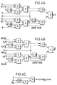
- the group of figures comprising Figure 4 illustrate an arrangement for keying two different foreground objects F1 and F2 over two respective copies of the same background B in which arrangement the two results are cross faded, as are the two internal keys. Subsequently the cross faded foregrounds F1 and F2 are keyed by a downstream keyeer into an external arbitrary background Bg.
- the initial background B is again assumed to be a black matte and thus to have a value notionally of 0.
- the foreground objects F1 and F2 may be symbols denoting different sports, for example a cricket bat and a tennis racket keyed into the top left hand corner of a black matte.
- the external background Bg may be a sports commentary of a cricket match and a tennis match, with the commentator switching at will between to two.
- the appropriate symbol is keyed into the external background Bg, and when the commentator switches from one match to the other, the two symbols F1 and F2 are cross faded.
- cross fading of the foregrounds F1 and F2 can be affected under control of the operator by a dissolve signal D, which determines the "profile" of the fade.
- the Figure 4 arrangement provides an output video V
- Figure 4(B) shows the circuit arrangement for producing the corresponding external key ⁇ derived from the two internal keys K1 and K2.
- V and ⁇ are applied to an external downstream keying circuit as illustrated in Figure 4(C).
- the circuit of Figure 4(C) is identical to that of Figure 2(A) and similar considerations regarding offset values apply.
- V and ⁇ are applied to the external keying circuit shown in Figure 4(C) together with the external background Bg, the following mathematics expresses the result R output therefrom.
- various video signals V which have previously been created by keying one or more foreground signals F onto a background matte signal B, are supplied to a downstream keyer together with an external keying signal ⁇ derived from the internal keying signals K used to produce the video signal.
- the derived external keying signal ⁇ is used to weight an arbitrary background signal Bg in the downstream keyer and the weighted background signal is then combined with the video signal V, unweighted, to produce the desired result.
- FIG. 5 An alternative arrangement allows a conventional keyer similar to that shown in Figure 1(C) of the accompanying drawings to be used.
- the keyer shown in Figure 1(C) is a widely available apparatus and by using such a keyer the costs of the system can be kept to a reasonable level.
- the alternative arrangement is shown in Figure 5 of the accompanying drawings and comprises a conventional source, such as a CYPHER character generator which provides a video signal V and a keying signal ⁇ similar to those signals already discussed hereinabove in relation to Figures 3 and 4 of the drawings, and a conventional keyer.
- the video signal comprises a foreground F keyed onto a black matte background B by a key K.
- the output video V and the internally derived external key ⁇ are output to a look up table LUT which divides V by ⁇ .
- a look up table LUT which divides V by ⁇ .
- the output from the look up table is delivered together with the external key ⁇ and an arbitrary background Bg to the conventional keyer which keys the ⁇ -divided video V onto the background using the key ⁇ . It will be noted that net effect of the look up table is to precondition the foreground signal F such that it is supplied unchanged to the conventional keyer.
- the look up table performs the inverse operation to that performed by the multipliers within the source.
- the look up table which may be a stand-alone unit but preferably is built into the source, serves to pre-compensate the background video V so that it is not processed for a second time by the same key data in the conventional keyer thereby ensuring that the background matte B is replaced completely by the external background Bg in the conventional keyer without the introduction of unwanted artefacts.
- the video signal is created by keying one or two foreground signals over a black matte background using a respective internal key for the or each foreground signal.
- An external key signal is derived from the internal keys and is subsequently used to combine the video signal with an external background signal of arbitrary content.
- the embodiments are not limited to the use of a video signal created from only one or two foreground signals and can be applied equally to a video signal formed from multiple foreground images so long as the keying signal for each foreground signal is available for use in deriving the external keying signal.
Abstract
Description
- This invention relates to video image keying systems and methods.
- Keying systems are widely used for picture editing and composition in television and are used to key a foreground image into a background image. For example a keying system may be used for keying letters or other characters forming a caption into a picture to provide information relating to the subject matter of the picture. In such a case video signals representing the characters, as selected by the operator, are generated by a source such as a character generator, for example the character generator sold by us under the trade mark "CYPHER". When a character is selected, the generator not only provides the video signals representing the character which may be regarded as foreground signals F, but it also provides internal control signals K which are used to key the character or foreground video signals over other video signals representing a background matte B. Normally the background matte B is a uniform black. The resulting combined signal is output from the source for further processing by other television image processing apparatus. The control signals K are also used within the source to key video signals representing white (value 1) over video signals representing black (value 0) to produce a key signal α which is output from the source for external use together with the combined signal. Thus, the output of the character generator comprises the video signal representation V of the foreground F keyed over the background B together with the external key α. The external key α is used subsequently in external circuitry as will be described in greater detail hereinafter.
- At present it is usual to perform the keying of the foreground F over the background matte B within the source character generator using a linear interpolating circuit in which the internal control signals K function as an interpolating co-efficient. The video V which is the result of the interpolation can then be represented by

It is also usual for the control signals K to have a maximum value, which may be 1 or less than 1, for pixels lying within the character represented by the video signals F and to havevalue 0 for pixels within the background matte B, except for a zone round the boundary of the character over which the control signals K decline gradually from the maximum value,eg 1, to 0 to produce a soft edge between the character F and the background matte B. As is well known, this so-called soft edged keying is employed to reduce aliasing which would otherwise arise between character and background. The maximum value of K will be less than 1 where a foreground image F is to be combined transparently with the background matte B. Thus the coefficient K in the above expression for V may have values in the range:
and it will be understood that similar soft edging will also appear in the external key signal α. In the accompanying drawings Figures 1(A) and 1(B) together illustrate a character generator or source of the above described form, conditioned to generate an output video as represented by the above expression for V and also to generate the above mentioned external key α. All the Figures in the drawings are in the form of schematic functional diagrams in which different circuits elements are represented by blocks identified by functional symbols denoting the nature of the respective circuit elements. Specific explanation of individual functional units in the drawings is considered to be unnecessary for an understanding of the invention by those possessed of the appropriate skills. - Returning to Figure 1(A) it will be appreciated that where K = 0 pixels in the video image V will relate solely to the matte background B, where K = 1 pixels in the video image V will relate solely to the foreground character F and that for pixels within the soft edges, where K is between 1 and 0, the output video V will include a contribution both from F and from the background B. In the special case where the background matte is black of
value 0, then the term B(1-K) will remain 0 regardless of the value of K, but the term F.K will diminish with K at the soft edges, thereby "darkening" the character, in effect increasing the contribution from black. It will also be appreciated from Figure 1(B) that the value of α will track that of K, being non-zero where K is non-zero. - The external key α is used by external circuitry to key the video signal V output from the source into video signals representing a picture which may be regarded as arbitrary external background Bg. In this way a resultant picture R is produced comprising the background picture Bg and the foreground character F. The external keying of the video V into the arbitrary external background Bg has hitherto usually been performed by another linear interpolation process as illustrated in Figure 1(c) to produce the result:

Bearing in mind that from equation (1) hereinabove
- The object of the present invention is to reduce the problem of spurious signals such as illustrated above. According to one aspect of the present invention there is provided an image processing system in which first image data, representing at least one foreground image keyed to a portion of a first background in accordance with respective keying data, is combined with second image data, representing a second background, to produce data defining a combined image comprising said at least one foreground image keyed to a portion of said second background, the system being arranged such that the second image data is weighted by control data derived from said keying data before being combined with the first image data such that data representing the first background is replaced by the second image data.
- According to another aspect of the invention there is provided a keying system for television image processing, the system comprising: a source of first video signals V representing a foreground object F keyed over a first background B; a source of second video signals representing an arbitrary background Bg; a source of key signals (α) for keying the foreground object over the arbitrary background Bg; and a keying circuit responsive to said first and second video signals and said key signals to produce the result

- On the condition that:-

the above results R is:
which yields the required blend for soft edging between the foreground and the arbitrary background, Bg, with no contribution in the Result from the background B. That is to say, the first background B is replaced by the new arbitrary background Bg in such a way as to avoid the introduction of spurious artefacts such as halos or shadows in the resultant image. - According to another aspect of the invention there is provided an image processing system comprising a first data source for supplying first image data representing a first image formed from at least one foreground image keyed to a first background image by interpolation in accordance with at least one respective first interpolation co-efficient and for supplying a second interpolation coefficient derived from the or each first interpolation coefficient, and a divider for dividing the first image data by the second interpolation co-efficient.
- In a further aspect the invention provides a method of processing image data, the method comprising supplying first image data representing a first image formed from first image data representing at least one foreground image keyed to a first background image by interpolation in accordance with at least one respective first interpolation co-efficient, deriving a second interpolation co-efficient from the or each first interpolation co-efficient, dividing the first image data by the second interpolation co-efficient. The above and further features of the invention are set forth with particularity in the appended claims and together with advantages thereof will become clearer from consideration of the following detailed description of exemplary embodiments of the invention given with reference to the accompanying drawings.
- In the drawings:
- Figure 1 illustrates a simple character generator at (a) and (b) and a prior art external keying process at (c) as previously discussed hereinabove.
- Figure 2 illustrates a simple external keying system according to the present invention;
- Figure 3 illustrates a system including an external keyer for keying overlapped foreground objects onto the same background;
- Figure 4 illustrates a system including an external keyer for keying two different foreground objects over respective copies of the same background and for cross fading between the two; and
- Figure 5 illustrates a system in which a foreground image is pre-processed before being delivered externally to a conventional keying circuit.
- Further reference will now be made to Figures 2 to 5 of the accompanying drawings, which illustrate several different exemplary embodiments of the invention. Turning first to Figure 2(A), there is illustrated a system including a simple external or so-called downstream keying circuit according to the invention. The keying circuit of Figure 2(A) operates on the video V output from the character source of Figure 1(A) under control of the key α output from the source shown in Figure 1(B). There is a second video input in Figure 2(A) namely a picture which can be regarded as an external arbitrary background Bg. It will be noted that in the downstream keying circuit of Figure 2(A) there is no multiplying circuit in the input path for V, as there would be if the keying circuit were a linear interpolating circuit such as used hitherto and illustrated in Figure 1(c) of the accompanying drawings. The Result which is output from the Figure 2(A) downstream keyer is given by the equation:

but
and if

- That is to say, the result R output from the external keyer circuit of Figure 2(A) is the foreground F keyed onto the external background Bg with no contribution from the original background B, which is the desired result.
- The condition that

luminance value 16 for black, and the second video signals representing the "external " arbitrary background might have black equal to sixteen in the scale of luminance signal values. In this event as illustrated in Figure 2 (B) of the accompanying drawings the black "offset" value of 16 would, in practice, be subtracted from both video signals V and Bg before applying them to the keying circuit, and would then be re-added to the Result. The circuit of Figure 2(B) can be simplified to the circuit of Figure 2 (C). - The invention would usually be applied to colour television signals in digital form comprising different channels for different colour components eg YUV or RGB. In this specification the description is confined to one channel, assumed to be the Y channel of a YUV system. For such a system the Y component to represent black has the value 16 (in the scale 0-255), as already discussed. For U and V components, the CCIR specification prescribes the value 128 (again on the
scale 0 to 255) for zero chroma, and appropriate measures for dealing with the offset are required in the U and V channels also. Similar considerations apply to the generation of the external keying signal α from the internal key signals K. - Figures 3(A), 3(B) and 3(C) illustrate a system for keying overlapping foreground objects F1 and F2 onto the same background B, followed by subsequent keying of the output over an external arbitrary background Bg. Figure 3(A) shows the circuit components for keying F1 and F2 and B, Figure 3(B) shows the circuit components for generating the external key α, while Figure 3(C) shows the external keying circuit. The video output from Figure 3(A) is represented by:-

The key signal output from Figure 3(B) is represented by:-
It will be noted that K₁ is the only output from the first of the two multiplying stages in Figure 3(B) because the video signal for black is 0. It will also be noted that the external or downstream keyer circuit of Figure 3(C) is exactly the same as that shown in Figure 2(A) and that similar considerations regarding the offset values of black as discussed hereinabove in relation to Figures 2(B) and (C). Since the Figure 3(C) downstream keyer is the same as that in Figure 2(A) it follows that the result R of the external keying operation performed in the Figure 3(C) circuit is again represented by the equation:
- If B = 0 in equation (3) then substituting:

- It should be noted that Bg (1-K₁) (1-K₂) is the same term as was applied to B in equation (3) and is therefore free from contributions from the original background B, as required.
- The arrangement illustrated by Figures 3(A), 3(B) and 3(C) can be used in an image composition system such as shown in our British Patent 2,113,950 and USA Patent 4,602,286.
- The group of figures comprising Figure 4 illustrate an arrangement for keying two different foreground objects F₁ and F₂ over two respective copies of the same background B in which arrangement the two results are cross faded, as are the two internal keys. Subsequently the cross faded foregrounds F₁ and F₂ are keyed by a downstream keyeer into an external arbitrary background Bg. The initial background B is again assumed to be a black matte and thus to have a value notionally of 0. As an illustration of the use to which the form of the invention may be put, the foreground objects F1 and F2 may be symbols denoting different sports, for example a cricket bat and a tennis racket keyed into the top left hand corner of a black matte. The external background Bg may be a sports commentary of a cricket match and a tennis match, with the commentator switching at will between to two. At any one time the appropriate symbol is keyed into the external background Bg, and when the commentator switches from one match to the other, the two symbols F1 and F2 are cross faded. As represented in Figure 4(A), cross fading of the foregrounds F1 and F2 can be affected under control of the operator by a dissolve signal D, which determines the "profile" of the fade. The Figure 4 arrangement provides an output video V, whilst Figure 4(B) shows the circuit arrangement for producing the corresponding external key α derived from the two internal keys K₁ and K₂. The expressions for the signals V and α are given by the following mathematics:


- Subsequently V and α are applied to an external downstream keying circuit as illustrated in Figure 4(C). Again it should be noted that the circuit of Figure 4(C) is identical to that of Figure 2(A) and similar considerations regarding offset values apply. When V and α are applied to the external keying circuit shown in Figure 4(C) together with the external background Bg, the following mathematics expresses the result R output therefrom.
- From equation (6)

- If B is 0 in equation (5) then

- Now


- This is the same term for Bg as was applied to B in equation (5) and is therefore the required result. That is to say, in the result R the original internal background B is replaced with the external background Bg with no residual contribution from the original background.
- In each of Figures 2, 3 and 4 various video signals V, which have previously been created by keying one or more foreground signals F onto a background matte signal B, are supplied to a downstream keyer together with an external keying signal α derived from the internal keying signals K used to produce the video signal. The derived external keying signal α is used to weight an arbitrary background signal Bg in the downstream keyer and the weighted background signal is then combined with the video signal V, unweighted, to produce the desired result.
- An alternative arrangement allows a conventional keyer similar to that shown in Figure 1(C) of the accompanying drawings to be used. The keyer shown in Figure 1(C) is a widely available apparatus and by using such a keyer the costs of the system can be kept to a reasonable level. The alternative arrangement is shown in Figure 5 of the accompanying drawings and comprises a conventional source, such as a CYPHER character generator which provides a video signal V and a keying signal α similar to those signals already discussed hereinabove in relation to Figures 3 and 4 of the drawings, and a conventional keyer. The video signal comprises a foreground F keyed onto a black matte background B by a key K. The output video V and the internally derived external key α are output to a look up table LUT which divides V by α. In setting up the look up table consideration must be given to the black offset in the foreground data F and the key data (see Figures 2B and 2C). The output from the look up table is delivered together with the external key α and an arbitrary background Bg to the conventional keyer which keys the α-divided video V onto the background using the key α. It will be noted that net effect of the look up table is to precondition the foreground signal F such that it is supplied unchanged to the conventional keyer. Once inside the keyer the foreground signal is multiplied by the external key α and added to the background weighted by (1-α) to produce the result

- In each of the above described embodiments the video signal is created by keying one or two foreground signals over a black matte background using a respective internal key for the or each foreground signal. An external key signal is derived from the internal keys and is subsequently used to combine the video signal with an external background signal of arbitrary content. The embodiments are not limited to the use of a video signal created from only one or two foreground signals and can be applied equally to a video signal formed from multiple foreground images so long as the keying signal for each foreground signal is available for use in deriving the external keying signal.
- Having thus described the present invention by reference to preferred embodiments it is to be well understood that the embodiments in question are exemplary only and that modifications and variations such as will occur to those possessed of appropriate knowledge and skills may be made without departure from the spirit and scope of the invention as set forth in the appended claims and equivalents thereof.
Claims (18)
- An image processing system in which first image data, representing at least one foreground image keyed to a portion of a first background in accordance with respective keying data, is combined with second image data, representing a second background, to produce data defining a combined image comprising said at least one foreground image keyed to a portion of said second background, the system being arranged such that the second image data is weighted by control data derived from said keying data before being combined with the first image data such that data representing the first background is replaced by the second image data.
- An image processing system as claimed in claim 1, wherein said first image data represents plural foreground images independently keyed to portions of said first background in accordance with respective plural keying data, and wherein said control data is derived from said plural keying data.
- An image processing system as claimed in claim 1 or 2 wherein the control data is derived by operating with said keying data on data representing image white and image black.
- An image processing system as claimed in any preceding claim, wherein said first background is a black matte.
- An image processing system as claimed in any preceding claim, wherein said first and second image data are combined by addition.
- An image processing system as claimed in any preceding claim, wherein said foreground and background images each comprise a plurality of picture elements and are combined on an element by element basis.
- An image processing system as claimed in any preceding claim, wherein the combined image data is output for display.
- A keying system for image processing, the system comprising:
a source of first video signals V representing at least one foreground object F keyed over a first background B;
a source of second video signals representing an arbitrary background Bg;
a source of key signals (α) for keying the foreground object over the arbitrary background Bg; and
a keying circuit responsive to said first and second video signals and said key signals to produce the result = V + Bg(1-α). - An image processing system comprising a first data source for supplying first image data representing a first image formed from at least one foreground image keyed to a first background image by interpolation in accordance with at least one respective first interpolation co-efficient and for supplying a second interpolation coefficient derived from the or each first interpolation coefficient, and a divider for dividing the first image data by the second interpolation co-efficient.
- An image processing system as claimed in claim 9, further comprising a second data source for supplying second image data representing a second background image, and a keying circuit for keying said divided first image data and said second image data by interpolation in accordance with the second interpolation co-efficient.
- An image processing system as claimed in claim 9 or 10, wherein said first background image is a black matte.
- An image processing system as claimed in claim 9 or 10 or 11, wherein the second interpolation coefficient is derived by interpolating between signals representing image black and image white in accordance with the or each said respective first interpolation co-efficient.
- An image processing system as claimed in any of claims 9 to 12, wherein the divider comprises a look-up table responsive to the first image data and said second interpolation coefficient for outputting data corresponding to said divided first image data.
- An image processing system as claimed in any of claims 10 to 13, wherein said first and second images each comprise a plurality of picture elements and said first and second data are keyed on a element by element basis.
- An image processing system as claimed in claim 14, wherein said at least one first and said second interpolation co-efficient are each defined on an element by element basis.
- A method of processing image data, the method comprising supplying first image data representing a first image formed from first image data representing at least one foreground image keyed to a first background image by interpolation in accordance with at least one respective first interpolation coefficient, deriving a second interpolation coefficient from the or each first interpolation coefficient, dividing the first image data by the second interpolation co-efficient.
- A method as claimed in claim 16, further comprising obtaining second image data representing a second background image, and keying said divided first image data and said second data by interpolation in accordance with the second interpolation co-efficient.
- A method as claimed in claim 16 or 17, wherein data in a look-up table is used to determine said divided first data from said first data.
Applications Claiming Priority (2)
| Application Number | Priority Date | Filing Date | Title |
|---|---|---|---|
| GB919109999A GB9109999D0 (en) | 1991-05-09 | 1991-05-09 | Improvements in or relating to keying systems and methods for television image processing |
| GB9109999 | 1991-05-09 |
Publications (2)
| Publication Number | Publication Date |
|---|---|
| EP0512839A2 true EP0512839A2 (en) | 1992-11-11 |
| EP0512839A3 EP0512839A3 (en) | 1993-08-18 |
Family
ID=10694680
Family Applications (1)
| Application Number | Title | Priority Date | Filing Date |
|---|---|---|---|
| EP19920304132 Withdrawn EP0512839A3 (en) | 1991-05-09 | 1992-05-08 | Image keying generator for video special effects |
Country Status (5)
| Country | Link |
|---|---|
| US (1) | US5428401A (en) |
| EP (1) | EP0512839A3 (en) |
| JP (1) | JPH05161065A (en) |
| GB (2) | GB9109999D0 (en) |
| HK (1) | HK81697A (en) |
Cited By (13)
| Publication number | Priority date | Publication date | Assignee | Title |
|---|---|---|---|---|
| WO1994022100A1 (en) * | 1993-03-25 | 1994-09-29 | Delean Bruno Camille Roger Jea | Method for processing an image in a computerized system |
| WO1997034261A1 (en) * | 1996-03-11 | 1997-09-18 | Avid Technology, Inc. | A computer system and process for defining and manufacturing images using structured objects with variable edge characteristics |
| US5790708A (en) * | 1993-03-25 | 1998-08-04 | Live Picture, Inc. | Procedure for image processing in a computerized system |
| EP0924649A2 (en) * | 1997-12-22 | 1999-06-23 | Adobe Systems Incorporated | Conversion of alpha-multiplied color data |
| US6016152A (en) * | 1997-08-01 | 2000-01-18 | Avid Technology, Inc. | Apparatus and method for non-uniform image scaling |
| WO2000038171A1 (en) * | 1998-12-19 | 2000-06-29 | Powertv, Inc. | Font anti-aliasing system |
| US6351557B1 (en) | 1998-04-03 | 2002-02-26 | Avid Technology, Inc. | Method and apparatus for color manipulation |
| US6417891B1 (en) | 1999-04-16 | 2002-07-09 | Avid Technology, Inc. | Color modification on a digital nonlinear editing system |
| US6477271B1 (en) | 2000-04-07 | 2002-11-05 | Avid Technology, Inc. | Secondary color modification of a digital image |
| US6552731B1 (en) | 1999-04-16 | 2003-04-22 | Avid Technology, Inc. | Multi-tone representation of a digital image on a digital nonlinear editing system |
| WO2008124263A1 (en) * | 2007-04-03 | 2008-10-16 | Lifetouch Inc. | Method and apparatus for background replacement in still photographs |
| EP2334051A1 (en) * | 2002-10-25 | 2011-06-15 | Sony Computer Entertainment Inc. | Method and apparatus for generating new images by using image data that vary along time axis |
| US7973800B2 (en) | 1999-04-16 | 2011-07-05 | Avid Technology, Inc. | Source color modification on a digital nonlinear editing system |
Families Citing this family (17)
| Publication number | Priority date | Publication date | Assignee | Title |
|---|---|---|---|---|
| GB2277847B (en) * | 1993-05-03 | 1997-08-20 | Grass Valley Group | Method of creating video effects by use of keyframes |
| JP3301679B2 (en) * | 1994-12-07 | 2002-07-15 | 松下電器産業株式会社 | Video composition circuit |
| US6128046A (en) * | 1995-05-12 | 2000-10-03 | Sony Corporation | Key signal generating apparatus and picture synthesis apparatus, and key signal generating method and picture synthesis method |
| US5719594A (en) * | 1995-10-06 | 1998-02-17 | International Business Machines Corporation | Method and system in a data processing system for improved video image resolution when enlarging a video sequence |
| DE19619090A1 (en) * | 1996-04-30 | 1997-11-13 | Cfb Gmbh | Device and method for generating a composite image |
| KR100616258B1 (en) * | 1996-05-06 | 2007-04-25 | 코닌클리케 필립스 일렉트로닉스 엔.브이. | Simultaneously displaying a graphic image and a video image |
| DE19622578C2 (en) * | 1996-06-05 | 1998-12-10 | Rovotech Elektronik Gmbh | Image signal processing device and digital mixer for image signals |
| US6301382B1 (en) * | 1996-06-07 | 2001-10-09 | Microsoft Corporation | Extracting a matte of a foreground object from multiple backgrounds by triangulation |
| DE19639355B4 (en) * | 1996-09-25 | 2006-05-04 | Bts Holding International Bv | Method and arrangement for color punching |
| US5986717A (en) * | 1997-06-27 | 1999-11-16 | Fairhurst; Jon A. | Real-time video production using recursive techniques |
| KR100238253B1 (en) * | 1997-08-29 | 2000-01-15 | 윤종용 | Method and apparatus for mixing video signals |
| GB9908811D0 (en) * | 1999-04-16 | 1999-06-09 | Sony Uk Ltd | Signal processor |
| US20030011713A1 (en) * | 2001-07-10 | 2003-01-16 | Kastelic John Andrew | Method and system for enhancing a graphic overlay on a video image |
| US20030011715A1 (en) * | 2001-07-10 | 2003-01-16 | Kastelic John A. | Method and system for enhancing a graphic overlay on a video image |
| EP1621010A1 (en) * | 2003-05-02 | 2006-02-01 | Allan Robert Staker | Interactive system and method for video compositing |
| US8824861B2 (en) * | 2008-07-01 | 2014-09-02 | Yoostar Entertainment Group, Inc. | Interactive systems and methods for video compositing |
| US10332560B2 (en) | 2013-05-06 | 2019-06-25 | Noo Inc. | Audio-video compositing and effects |
Citations (3)
| Publication number | Priority date | Publication date | Assignee | Title |
|---|---|---|---|---|
| GB2113950A (en) * | 1982-01-15 | 1983-08-10 | Quantel Ltd | Image composition system |
| EP0236943A2 (en) * | 1986-03-06 | 1987-09-16 | The Grass Valley Group, Inc. | Apparatus for combining video signals |
| EP0360518A1 (en) * | 1988-09-19 | 1990-03-28 | The Grass Valley Group, Inc. | Improved video luminance self keyer |
Family Cites Families (17)
| Publication number | Priority date | Publication date | Assignee | Title |
|---|---|---|---|---|
| CA1165433A (en) * | 1979-09-04 | 1984-04-10 | Grass Valley Group, Inc. (The) | Chroma keying system |
| CA1187166A (en) * | 1981-07-09 | 1985-05-14 | Kaichi Yamamoto | Digital chromakey apparatus |
| JPS5846783A (en) * | 1981-09-12 | 1983-03-18 | Sony Corp | Chromakey device |
| DE3143653A1 (en) * | 1981-11-04 | 1983-05-11 | Robert Bosch Gmbh, 7000 Stuttgart | METHOD FOR MIXING TWO COLOR TV SIGNALS |
| GB2158318A (en) * | 1984-04-26 | 1985-11-06 | Philips Electronic Associated | Fading circuit for video signals |
| US4758892A (en) * | 1984-04-27 | 1988-07-19 | Ampex Corporation | System for producing a video combine from multiple video images |
| US4970595A (en) * | 1985-04-12 | 1990-11-13 | Ampex Corporation | Apparatus and method for processing video signals with key signals in accordance with previous processing of the video signals |
| JPS62502792A (en) * | 1985-04-12 | 1987-10-22 | アムペツクス コ−ポレ−シヨン | Apparatus and method for processing previously processed video signals |
| US4698666A (en) * | 1985-07-12 | 1987-10-06 | The Grass Valley Group, Inc. | Video key glow and border generator |
| US4851912A (en) * | 1986-03-06 | 1989-07-25 | The Grass Valley Group, Inc. | Apparatus for combining video signals |
| US4991014A (en) * | 1987-02-20 | 1991-02-05 | Nec Corporation | Key signal producing apparatus for video picture composition |
| US4853784A (en) * | 1988-02-19 | 1989-08-01 | The Grass Valley Group, Inc. | Video switcher with independent processing of selected video signals |
| DE3900489C2 (en) * | 1989-01-10 | 1996-04-04 | Broadcast Television Syst | Device for generating control signals for a video mixing device |
| US4947254A (en) * | 1989-04-27 | 1990-08-07 | The Grass Valley Group, Inc. | Layered mix effects switcher architecture |
| GB2243743A (en) * | 1990-04-11 | 1991-11-06 | Rank Cintel Ltd | Digital colour video key signal generator using two programmable lookup tables |
| US5115314A (en) * | 1990-04-26 | 1992-05-19 | Ross Video Limited | Video keying circuitry incorporating time division multiplexing |
| JP3042062B2 (en) * | 1991-08-28 | 2000-05-15 | ソニー株式会社 | Image processing device |
-
1991
- 1991-05-09 GB GB919109999A patent/GB9109999D0/en active Pending
-
1992
- 1992-05-08 EP EP19920304132 patent/EP0512839A3/en not_active Withdrawn
- 1992-05-08 JP JP4116389A patent/JPH05161065A/en not_active Withdrawn
- 1992-05-08 GB GB9210011A patent/GB2256557B/en not_active Expired - Lifetime
- 1992-05-08 US US07/880,236 patent/US5428401A/en not_active Expired - Lifetime
-
1997
- 1997-06-19 HK HK81697A patent/HK81697A/en not_active IP Right Cessation
Patent Citations (3)
| Publication number | Priority date | Publication date | Assignee | Title |
|---|---|---|---|---|
| GB2113950A (en) * | 1982-01-15 | 1983-08-10 | Quantel Ltd | Image composition system |
| EP0236943A2 (en) * | 1986-03-06 | 1987-09-16 | The Grass Valley Group, Inc. | Apparatus for combining video signals |
| EP0360518A1 (en) * | 1988-09-19 | 1990-03-28 | The Grass Valley Group, Inc. | Improved video luminance self keyer |
Non-Patent Citations (1)
| Title |
|---|
| SMPTE JOURNAL vol. 95, no. 5, May 1986, WHITE PLAINS, NY, USA pages 557 - 561 WOOD AND MACCLYMONT 'New developments in electronic character generation' * |
Cited By (28)
| Publication number | Priority date | Publication date | Assignee | Title |
|---|---|---|---|---|
| US6181836B1 (en) | 1993-03-25 | 2001-01-30 | Mgi Software Corporation | Method and system for non-destructive image editing |
| US6763146B2 (en) | 1993-03-25 | 2004-07-13 | Roxio, Inc. | Method and system for image processing |
| AU681641B2 (en) * | 1993-03-25 | 1997-09-04 | Mgi Software Corporation | Method for processing an image in a computerized system |
| USRE43747E1 (en) | 1993-03-25 | 2012-10-16 | Intellectual Ventures I Llc | Method and system for image processing |
| US6512855B1 (en) | 1993-03-25 | 2003-01-28 | Roxio, Inc. | Method and system for image processing |
| US5790708A (en) * | 1993-03-25 | 1998-08-04 | Live Picture, Inc. | Procedure for image processing in a computerized system |
| US5907640A (en) * | 1993-03-25 | 1999-05-25 | Live Picture, Inc. | Functional interpolating transformation system for image processing |
| WO1994022100A1 (en) * | 1993-03-25 | 1994-09-29 | Delean Bruno Camille Roger Jea | Method for processing an image in a computerized system |
| FR2703170A1 (en) * | 1993-03-25 | 1994-09-30 | Delean Bruno Camille Roger | Method of processing an image in a computer system |
| US5754180A (en) * | 1996-03-11 | 1998-05-19 | Avid Technology, Inc. | Computer system and process for defining and manipulating images using structured objects with variable edge characteristics |
| WO1997034261A1 (en) * | 1996-03-11 | 1997-09-18 | Avid Technology, Inc. | A computer system and process for defining and manufacturing images using structured objects with variable edge characteristics |
| US6016152A (en) * | 1997-08-01 | 2000-01-18 | Avid Technology, Inc. | Apparatus and method for non-uniform image scaling |
| EP0924649A2 (en) * | 1997-12-22 | 1999-06-23 | Adobe Systems Incorporated | Conversion of alpha-multiplied color data |
| EP0924649A3 (en) * | 1997-12-22 | 2001-06-13 | Adobe Systems Incorporated | Conversion of alpha-multiplied color data |
| US6351557B1 (en) | 1998-04-03 | 2002-02-26 | Avid Technology, Inc. | Method and apparatus for color manipulation |
| WO2000038171A1 (en) * | 1998-12-19 | 2000-06-29 | Powertv, Inc. | Font anti-aliasing system |
| US6933948B2 (en) | 1999-04-16 | 2005-08-23 | Avid Technology, Inc. | Multi-tone representation of a digital image on a digital nonlinear editing system |
| US6417891B1 (en) | 1999-04-16 | 2002-07-09 | Avid Technology, Inc. | Color modification on a digital nonlinear editing system |
| US7973800B2 (en) | 1999-04-16 | 2011-07-05 | Avid Technology, Inc. | Source color modification on a digital nonlinear editing system |
| US6552731B1 (en) | 1999-04-16 | 2003-04-22 | Avid Technology, Inc. | Multi-tone representation of a digital image on a digital nonlinear editing system |
| US6477271B1 (en) | 2000-04-07 | 2002-11-05 | Avid Technology, Inc. | Secondary color modification of a digital image |
| US6763134B2 (en) | 2000-04-07 | 2004-07-13 | Avid Technology, Inc. | Secondary color modification of a digital image |
| EP2334051A1 (en) * | 2002-10-25 | 2011-06-15 | Sony Computer Entertainment Inc. | Method and apparatus for generating new images by using image data that vary along time axis |
| US7990385B2 (en) | 2002-10-25 | 2011-08-02 | Sony Computer Entertainment Inc. | Method and apparatus for generating new images by using image data that vary along time axis |
| US7834894B2 (en) | 2007-04-03 | 2010-11-16 | Lifetouch Inc. | Method and apparatus for background replacement in still photographs |
| WO2008124263A1 (en) * | 2007-04-03 | 2008-10-16 | Lifetouch Inc. | Method and apparatus for background replacement in still photographs |
| US8134576B2 (en) | 2007-04-03 | 2012-03-13 | Lifetouch Inc. | Method and apparatus for background replacement in still photographs |
| US8319797B2 (en) | 2007-04-03 | 2012-11-27 | Lifetouch Inc. | Method and apparatus for background replacement in still photographs |
Also Published As
| Publication number | Publication date |
|---|---|
| GB2256557B (en) | 1995-09-27 |
| GB9210011D0 (en) | 1992-06-24 |
| HK81697A (en) | 1997-06-27 |
| GB9109999D0 (en) | 1991-07-03 |
| US5428401A (en) | 1995-06-27 |
| GB2256557A (en) | 1992-12-09 |
| JPH05161065A (en) | 1993-06-25 |
| EP0512839A3 (en) | 1993-08-18 |
Similar Documents
| Publication | Publication Date | Title |
|---|---|---|
| EP0512839A2 (en) | Image keying generator for video special effects | |
| EP0264965B1 (en) | Video difference key generator | |
| US5416529A (en) | Method and system for digital video processing with combined downstream keyer and fade to black mixer | |
| US6342951B1 (en) | Gamut mapping algorithm using inverted gamma function | |
| US5313275A (en) | Chroma processor including a look-up table or memory | |
| US4853784A (en) | Video switcher with independent processing of selected video signals | |
| EP0122098B1 (en) | Font recall system for selective insertion as a caption into a video image | |
| US4755870A (en) | Coloring a black and white signal using motion detection | |
| US6075887A (en) | High definition color modification | |
| JPH0473189B2 (en) | ||
| US4862256A (en) | Method of, and apparatus for, coloring a black and white video signal | |
| US6262778B1 (en) | Image processing system | |
| US5305107A (en) | Combining digital video key signals | |
| GB2254517A (en) | Video signal colour correction | |
| EP0790744A2 (en) | Backing color and luminance non-uniformity compensation for linear image compositing | |
| JPH04127675A (en) | Digital picture formation | |
| JP3449860B2 (en) | Image sharpness processing device | |
| US5218350A (en) | Image processing method for dodging with softened edge transitions | |
| EP0318149B1 (en) | Video processing | |
| US5313304A (en) | Chroma keyer with fringe control offset | |
| WO2004015618A1 (en) | Visible-invisible background prompter | |
| EP0236943B1 (en) | Apparatus for combining video signals | |
| EP0285271B1 (en) | Character and other graphical generating system and method for video display | |
| GB2107955A (en) | Chroma-key signal generator | |
| GB2287601A (en) | Self keyer with background gap fill |
Legal Events
| Date | Code | Title | Description |
|---|---|---|---|
| PUAI | Public reference made under article 153(3) epc to a published international application that has entered the european phase |
Free format text: ORIGINAL CODE: 0009012 |
|
| AK | Designated contracting states |
Kind code of ref document: A2 Designated state(s): DE FR GB |
|
| PUAL | Search report despatched |
Free format text: ORIGINAL CODE: 0009013 |
|
| AK | Designated contracting states |
Kind code of ref document: A3 Designated state(s): DE FR GB |
|
| 17P | Request for examination filed |
Effective date: 19940202 |
|
| 17Q | First examination report despatched |
Effective date: 19960312 |
|
| STAA | Information on the status of an ep patent application or granted ep patent |
Free format text: STATUS: THE APPLICATION IS DEEMED TO BE WITHDRAWN |
|
| 18D | Application deemed to be withdrawn |
Effective date: 19970916 |