EP0513402A1 - Method of compensating for non-linearities in an amplifying circuit with strong signal passage time - Google Patents
Method of compensating for non-linearities in an amplifying circuit with strong signal passage time Download PDFInfo
- Publication number
- EP0513402A1 EP0513402A1 EP19910106653 EP91106653A EP0513402A1 EP 0513402 A1 EP0513402 A1 EP 0513402A1 EP 19910106653 EP19910106653 EP 19910106653 EP 91106653 A EP91106653 A EP 91106653A EP 0513402 A1 EP0513402 A1 EP 0513402A1
- Authority
- EP
- European Patent Office
- Prior art keywords
- amplifier circuit
- signal
- input signal
- coefficients
- output signal
- Prior art date
- Legal status (The legal status is an assumption and is not a legal conclusion. Google has not performed a legal analysis and makes no representation as to the accuracy of the status listed.)
- Withdrawn
Links
Images


Classifications
-
- H—ELECTRICITY
- H03—ELECTRONIC CIRCUITRY
- H03H—IMPEDANCE NETWORKS, e.g. RESONANT CIRCUITS; RESONATORS
- H03H21/00—Adaptive networks
- H03H21/0012—Digital adaptive filters
- H03H21/0025—Particular filtering methods
- H03H21/0027—Particular filtering methods filtering in the frequency domain
-
- H—ELECTRICITY
- H03—ELECTRONIC CIRCUITRY
- H03F—AMPLIFIERS
- H03F1/00—Details of amplifiers with only discharge tubes, only semiconductor devices or only unspecified devices as amplifying elements
- H03F1/32—Modifications of amplifiers to reduce non-linear distortion
- H03F1/3241—Modifications of amplifiers to reduce non-linear distortion using predistortion circuits
- H03F1/3247—Modifications of amplifiers to reduce non-linear distortion using predistortion circuits using feedback acting on predistortion circuits
Definitions
- the invention relates to a method for compensating for non-linearities of an amplifier circuit with a pronounced signal throughput time, in which an input signal s (t) is amplified to an output signal y (t) using a predetermined amplifier circuit (e.g. power amplifier for audio signals), which has non-linearities,
- a predetermined amplifier circuit e.g. power amplifier for audio signals
- Amplifier circuits in particular high-performance sound amplifiers, such as those used for modulating radio transmitters in the LW, MW and KW range, are usually fraught with non-linearities which must be eliminated.
- the classic solution for linearizing the characteristic provides for feedback of the output signal (feedback). The degree of this feedback depends on the characteristics of the amplifier in the non-feedback state.
- the object of the invention is to provide a method of the type mentioned at the outset, which ensures linear amplification, in particular for audio signals, using modern high-performance amplifiers and is free from instabilities.
- feed forward control which does not include a closed loop (open loop). It is based on the same amplifier model as that Feedback solution, but uses the determined coefficients in a different way.
- feed forward control in a predistortion filter in the sense of an open feedforward control using only the given input signal x (t) of the amplifier circuit and the coefficients k 1, ..., k L and the throughput time t d of the amplifier circuit to an input signal s (t) additive compensation signal c (t) is formed. This compensation signal c (t) is added to the input signal s (t) (predistortion). Finally, the resulting sum signal is fed as an input signal x (t) to the amplifier circuit, which has non-linearities.
- the compensation signal is first constructed in the Fourier space and then brought into the time domain by means of a fast Fourier transformation (FFT).
- FFT fast Fourier transformation
- the Fourier coefficients C n (i) of the additive compensation signal c (t) are according to the relationship determined.
- K -K c k1 (i) ⁇ n (i) [jn ⁇ T s / N + K c k12 (i) ⁇ n (i)] ⁇ 1
- K c is an arbitrarily definable constant that has no influence on the control principle. However, if it is chosen appropriately, the convergence of the compensation method can be improved.
- ⁇ (i) is determined according to the invention using the determined coefficients k 1 (i), ..., k L (i) according to the method of least squares. If ⁇ (i) has been determined from the over-determined system of equations, then the throughput time t d (i-1) is also defined (apart from integer multiples of T s ).
- the immediate input signal x (t) of the non-linear amplifier circuit is delayed in accordance with the first approximation t d0 of the throughput time compared to the output signal y (t).
- a high-performance amplifier with a linear characteristic is therefore available to the user of the circuit according to the invention.
- the preferably digital predistortion filter can namely easily be accommodated in the housing of the power amplifier in question.
- FIG. 1 shows a circuit diagram for wiring an amplifier circuit 1 in accordance with the invention.
- the predefined amplifier circuit for example a high-power amplifier, has a non-linear characteristic and a pronounced signal throughput time t d . This has to As a result, intermodulation would occur if the input signal s (t) were amplified directly without any precautions.
- the input signal s (t) is therefore first fed to a predistortion filter 3 which carries out a suitable predistortion.
- the predistorted signal x (t) is then raised by the amplifier circuit 1 to the required power level.
- the parameters of the predistortion are with an identification processor 2 from input and output signal x (t) and. y (t) of the amplifier circuit 1 is obtained.
- predistortion represents an essential feature of the invention. It will be explained in detail below taking into account the mathematical background.
- FIG. 2 The principle of identification emerges from FIG. 2. It is based on the evaluation of the input and output signals x (t) and. y (t) of the amplifier circuit 1 and runs essentially on the digital level and in the Fourier space.
- the input signal x (t) is first delayed by a delay element 20 by a fixed predetermined time interval t d0 .
- the delay corresponds in a first approximation to the transit time t d of the signal that actually occurs in the amplifier circuit.
- the delayed input signal x (tt d0 ) is then sampled and digitized in an A / D converter 21 at a rate 1 / T s .
- equations (V) and (VI) can of course be evaluated with the same effect, which assume that the quadratic and cubic signals x2 (t) and. x3 (t) can be calculated and then the FFT operation is performed:
- the output signal y (t) of the amplifier circuit 1 is digitized in the same way as x (t) (A / D converter 24) and Fourier-transformed (FFT computer 25).
- y m (i) denotes the digitized output signal.
- ⁇ 2 are now based on the auxiliary variables , ..., L ⁇ - and the Fourier coefficient Y n (i) the parameters of the model, ie the coefficients k1, k2, k3 and the lead time t d estimated.
- the 2N equations of the form used belong to the 2N samples per calculation cycle.
- t d can also be calculated in a modified manner.
- the invention is therefore not limited to the method for determining the throughput time just described.
- the amplifier characteristic is constantly identified anew, so that the end result is adaptive compensation of the non-linearity.
- the identification processor described here is therefore only to be understood as one of several equivalent options. Accordingly, the invention is not to be seen in this narrow scope.
- the time delay of the input signal x (t) in the identification processor can also only be introduced at the digital level.
- the relevant formulas can also be evaluated in other ways (e.g. in several individual steps). It is only important that the end result is a solution that can be expressed mathematically in the explicitly given way.
- the complex quantities A n (i) and B n (i) supplied by the identification processor 2 are delayed by a control cycle in a delay element 31. Then with a first and a second multiplier 32 and 33, the two summands A n (i-1) k2 (i) and B n (i-1) k3 (i) are formed and added in a summing element 34. The resulting sum is weighted in a further multiplier 35 by a certain factor -K.
- the Fourier coefficients C n (i) of the correction signal are thus available.
- An FFT 1 computer 36 uses the fast inverse Fourier transformation to determine the digital correction signal c m (i) in the time domain, which is finally converted into an analog signal c (t) by a D / A converter 37 and to the input signal s (t) is added (summing element 38).
- the weighting factor -K can optionally be determined from one of the following two relationships: or K c denotes a freely selectable constant (gain) that does not affect the predistortion as such, but only its convergence behavior.
- the weighting factor is determined in a computing element 30.
- FIGS. 4 and 5 show an example of a predistortion filter 4 based on the feedback principle.
- Amplifier circuit 1 and identification processor 2 are switched and designed as in the first embodiment.
- the input signal s (t) is passed, among other things, to an adjustable delay element 48 which introduces a time delay corresponding to the estimated throughput time t d (i).
- the delayed input signal is divided into two paths. In one generates a partial signal generator 49 a partial signal ⁇ e / ⁇ c of the form which is subsequently multiplied in a multiplier 42 by a fixed weighting factor -K c . In the other path there is an amplification with the coefficient k 1 (i) (multiplier 40).
- the difference signal e (t) is multiplied by the partial signal ⁇ e / ⁇ c (multiplier 43) and then integrated on the one hand in the integrator 45 and on the other hand multiplied by the determined throughput time t d (multiplier 44) according to
- the compensation signal c (t) is added to the undelayed input signal s (t) (summing element 47).
- the desired input signal x (t) is thus available to the amplifier circuit.
- the input signal s (t) resp. the output signal y (t) of the amplifier circuit 1 are respectively from an A / D converter 50. 58 scanned and digitized.
- the digital input signal s m (i) is delayed in an adjustable delay element 52 in accordance with the determined throughput time t d (i) and amplified with the linear coefficient k 1 (i) (multiplier 53).
- the input signal processed in this way is generated by the digitized output signal y m subtracted (summing element 54).
- the resulting (digital) difference signal e m (i) is subjected to a fast Fourier transformation in an FFT computer 55:
- the error signal generator 56 generates the desired error signal c m (i):
- the identification according to the invention and the compensation (predistortion) can also be used alone.
- the predistortion can certainly be based on a different type of identification, provided the latter provides the desired coefficients and processing times.
- the invention enables the linearization of non-linear characteristic curves, as are required in particular in the case of high-performance amplifiers in communications technology.
Landscapes
- Physics & Mathematics (AREA)
- Nonlinear Science (AREA)
- Engineering & Computer Science (AREA)
- Power Engineering (AREA)
- Amplifiers (AREA)
Abstract
Description
Die Erfindung betrifft ein Verfahren zur Kompensation von Nichtlinearitäten einer Verstärkerschaltung mit ausgeprägter Signaldurchlaufszeit, bei welchem ein Eingangssignal s(t) unter Verwendung einer vorgegebenen, mit Nichtlinearitäten behafteten Verstärkerschaltung (z.B. Leistungsverstärker für Audiosignale) zu einem Ausgangssignal y(t) verstärkt wird,The invention relates to a method for compensating for non-linearities of an amplifier circuit with a pronounced signal throughput time, in which an input signal s (t) is amplified to an output signal y (t) using a predetermined amplifier circuit (e.g. power amplifier for audio signals), which has non-linearities,
Verstärkerschaltungen, insbesondere Tonverstärker hoher Leistung, wie sie zur Modulation von Rundfunksendern im LW-, MW- und KW-Bereich eingesetzt werden, sind üblicherweise mit Nichtlinearitäten behaftet, die es zu eliminieren gilt. Die klassische Lösung zur Linearisierung der Charakteristik sieht eine Rückführung des Ausgangssignals vor (Feedback). Das Mass dieser Rückführung hängt von der Charakteristik des Verstärkers im nichtrückgekoppelten Zustand ab.Amplifier circuits, in particular high-performance sound amplifiers, such as those used for modulating radio transmitters in the LW, MW and KW range, are usually fraught with non-linearities which must be eliminated. The classic solution for linearizing the characteristic provides for feedback of the output signal (feedback). The degree of this feedback depends on the characteristics of the amplifier in the non-feedback state.
Aus der Regelungstechnik ist bekannt, wie bei linearen Verzerrungen einer Schaltung die Rückführung zu konzipieren ist, damit insgesamt eine lineare Charakteristik entsteht. Heutige nichtlineare Verstärkungsverfahren schliessen die lineare Rückführung oft aus regelungstechnischen Stabilitätsgründen aus. Die nicht vernachlässigbaren SignalDurchlaufszeiten können nämlich bei nicht durchdachter Rückführung das Verstärkungsverfahren instabil machen.From control engineering it is known how to design the feedback in the case of linear distortions of a circuit so that overall a linear characteristic is produced. Today's non-linear amplification methods often rule out linear feedback for reasons of control stability. The non-negligible signal throughput times can make the amplification process unstable if the feedback is not carefully considered.
Aufgabe der Erfindung ist es nun, ein Verfahren der eingangs genannten Art anzugeben, welches insbesondere für Audiosignale eine lineare Verstärkung unter Verwendung moderner Hochleistungsverstärker gewährleistet und frei von Instabilitäten ist.The object of the invention is to provide a method of the type mentioned at the outset, which ensures linear amplification, in particular for audio signals, using modern high-performance amplifiers and is free from instabilities.
Erfindungsgemäss besteht die Lösung darin, dass bei einem Verfahren der eingangs genannten Art
- a) eine vorgegebene Zahl L von Koeffizienten k₁, ..., kL sowie eine Durchlaufszeit td der Verstärkerschaltung entsprechend dem Modell

- b) in einem Vorverzerrungsfilter das Eingangssignal s(t) unter Verwendung des tatsächlichen Ausgangssignals y(t) und der Koeffizienten k₁, ..., kL sowie der Durchlaufszeit td der Verstärkerschaltung im Sinn einer Feedback-Steuerung zum Eingangssignal x(t) vorverzerrt wird, und
- c) das vorverzerrte Eingangssignal x(t) der mit Nichtlinearitäten behafteten Verstärkerschaltung zugeführt wird.
- a) a predetermined number L of coefficients k₁, ..., k L and a throughput time t d of the amplifier circuit according to the model
- b) the input signal s (t) in a predistortion filter using the actual output signal y (t) and the
coefficients k 1, ..., L and the throughput time t d of the amplifier circuit is predistorted in the sense of feedback control to the input signal x (t), and - c) the predistorted input signal x (t) is fed to the amplifier circuit which is subject to non-linearities.
Der Kern der Erfindung liegt darin, dass die Charakteristik der Verstärkerschaltung, welche eine ausgeprägte Signaldurchlaufszeit und eine nichtlineare Amplitudenverstärkung aufweist, entsprechend dem Modell
identifiziert wird und dass in einem vorgeschalteten Vorverzerrungsfilter das Eingangssignal s(t) gemäss diesem Modell (d.h. den Koeffizienten k₁, k₂,..., kL und der bestimmten Durchlaufszeit td) so vorverzerrt wird, dass am Ausgang der Verstärkerschaltung ein gewünschtes linear verstärktes Ausgangssignal ![]()
is identified and that in an upstream predistortion filter the input signal s (t) according to this model (ie the ![]()
In der früheren Europäischen Anmeldung 90113326.4 (Anmeldetag 12.7.90) wurde ein Lösungsansatz gewählt, der zwar auch der Signallaufzeit Rechnung trägt, allerdings nur in beschränktem Umfang (nämlich nur für sehr kleine Verzögerungen). Dadurch, dass es nun gelungen ist, die Signalverzögerung einerseits unabhängig von ihrer Grösse zu bestimmen und andererseits voll in die Vorverzerrung miteinzubeziehen, ist es möglich geworden, auch schwingungsfreie Vorverzerrung nach dem Prinzip des Feedbacks zu verwirklichen.In the earlier European application 90113326.4 (filing date July 12, 90), a solution was chosen that also takes the signal propagation time into account, but only to a limited extent (namely only for very small delays). The fact that it has now been possible to determine the signal delay independently of its size on the one hand and to fully include it in the predistortion on the other hand has made it possible to implement vibration-free predistortion according to the principle of feedback.
Die Vorverzerrung nach dem Feedback-Prinzip läuft im einzelnen vorzugsweise wie folgt ab:
- a) das Eingangssignal s(t) (d.h. das zu verstärkende Audiosignal) wird entsprechend der zuvor bestimmten Durchlaufszeit td verzögert;
- b) das verzögerte Eingangssignal s(t-td) wird mit dem entsprechend dem Modell ermittelten, aktuellen linearen Koeffizienten k₁(i) multipliziert,um y*(t) zu bilden;
- c) aus dem verzögerten und multiplizierten Eingangssignal s(t) und dem Ausgangssignal y(t) der Verstärkerschaltung wird ein Differenzsignal e(t) gebildet:


- d) das Differenzsignal wird mit einem Teilsignal ∂e/∂c der Form

- e) ein stabiles Kompensationssignal c(t) wird gemäss

- f) als vorverzerrtes Eingangssignal x(t) der Verstärkerschaltung wird das Summensignal aus Kompensationssignal c(t) und Eingangssignal s(t) verwendet:

The predistortion according to the feedback principle preferably proceeds as follows:
- a) the input signal s (t) (ie the audio signal to be amplified) is delayed in accordance with the previously determined throughput time t d ;
- b) the delayed input signal s (tt d ) is multiplied by the current linear coefficient k 1 (i) determined in accordance with the model to form y * (t);
- c) a difference signal e (t) is formed from the delayed and multiplied input signal s (t) and the output signal y (t) of the amplifier circuit:
- d) the difference signal with a partial signal ∂e / ∂c of the form
- e) a stable compensation signal c (t) is according to
- f) the sum signal from the compensation signal c (t) and the input signal s (t) is used as the predistorted input signal x (t) of the amplifier circuit:
Eine Alternative zur Feedback-Steuerung stellt die Feedforward-Steuerung dar, die keine geschlossene Schleife beinhaltet (open loop). Sie basiert auf dem selben Verstärkermodell wie die Feedback-Lösung, verwendet aber die ermittelten Koeffizienten auf andere Weise. Im Unterschied zur oben erwähnten Lösung wird in einem Vorverzerrungsfilter im Sinn einer offenen Feedforward-Steuerung allein unter Verwendung des gegebenen Eingangssignal x(t) der Verstärkerschaltung sowie der Koeffizienten k₁, ..., kL und der Durchlaufszeit td der Verstärkerschaltung ein zum Einganssignal s(t) additives Kompensationssignal c(t) gebildet wird. Dieses Kompensationssignal c(t) wird zum Eingangssignal s(t) hinzuaddiert (Vorverzerrung). Schliesslich wird das resultierende Summensignal als Eingangssignal x(t) der mit Nichtlinearitäten behafteten Verstärkerschaltung zugeführt.An alternative to feedback control is feed forward control, which does not include a closed loop (open loop). It is based on the same amplifier model as that Feedback solution, but uses the determined coefficients in a different way. In contrast to the solution mentioned above, in a predistortion filter in the sense of an open feedforward control using only the given input signal x (t) of the amplifier circuit and the
Gemäss einer bevorzugten Ausführungsform wird bei der Feedforward-Lösung das Kompensationssignal zunächst im Fourierraum konstruiert und dann mittels einer schnellen Fouriertransformation (FFT) in den Zeitbereich gebracht.According to a preferred embodiment, in the feedforward solution the compensation signal is first constructed in the Fourier space and then brought into the time domain by means of a fast Fourier transformation (FFT).
Die Fourierkoeffizienten Cn(i) des additiven Kompensationssignals c(t) werden gemäss der Beziehung

ermittelt. Der Koeffizient K kann wahlweise nach einer einfachen oder einer komplizierten Relation ermittelt werden. Im einfachen Fall gilt
![]()
The Fourier coefficients C n (i) of the additive compensation signal c (t) are according to the relationship
determined. The coefficient K can be determined either according to a simple or a complicated relation. In the simple case applies
![]()
Die präzisere, wenn auch um einiges aufwendigere Variante lautet:
![]()
Kc ist eine beliebig vorgebbare Konstante, die auf das Steuerungsprinzip keinen Einfluss hat. Wenn sie allerdings geeignet gewählt wird, dann kann die Konvergenz des Kompensationsverfahrens verbessert werden.The more precise, albeit a lot more complex variant is:
![]()
K c is an arbitrarily definable constant that has no influence on the control principle. However, if it is chosen appropriately, the convergence of the compensation method can be improved.
Die Identifikation der Koeffizienten und der Durchlaufszeit wird vorzugsweise wie folgt durchgeführt:
- a) Das Eingangssignal x(t) und das Ausgangssignal y(t) der Verstärkerschaltung werden mit einer
Abtastrate 1/Ts abgetastet und einer schnellen Fouriertransformation unterworfen; - b) Bei einer zuvor bestimmten Durchlaufszeit td(i-1) wird eine vorgegebene Zahl L von Koeffizienten k₁, ..., kL der Verstärkerschaltung entsprechend dem Modell


Dabei stellt td0 eine erste grobe Näherung für Durchlaufszeit td(i-1) dar. Zu Beginn kann td(i-1) ohne weiteres gleich td0 resp. α(i-1) = 1 gesetzt werden. Im Idealfall stellt ja td0 ohnehin die tatsächliche (resp. die optimale Schätzung der) Durchlaufszeit dar.The identification of the coefficients and the lead time is preferably carried out as follows:
- a) The input signal x (t) and the output signal y (t) of the amplifier circuit are sampled at a
sampling rate 1 / T s and subjected to a fast Fourier transformation; - b) With a previously determined cycle time t d (i-1), a predetermined number L of
coefficients k 1, ..., k L of the amplifier circuit according to the model
Here, t d0 represents a first rough approximation for throughput time t d (i-1). At the beginning, t d (i-1) can easily equal t d0 or α (i-1) = 1 can be set. Ideally, t represents d d0 anyway the actual (or the optimal estimate of) the throughput time.
Zur adaptiven Bestimmung der Durchlaufszeit td(i) wird das überbestimmte Gleichungssystem (2N Gleichungen)
wobei
![]()
gilt, herangezogen. α(i) wird erfindungsgemäss unter Verwendung der ermittelten Koeffizienten k₁(i), ..., kL(i) nach der Methode der kleinsten Fehlerquadrate bestimmt. Wenn α(i) aus dem überbestimmten Gleichungssystem ermittelt worden ist, dann ist auch die Durchlaufszeit td(i-1) definiert (bis auf ganzzahlige Vielfache von Ts).The overdetermined system of equations (2N equations) is used to adaptively determine the throughput time t d (i).
in which
![]()
applies. α (i) is determined according to the invention using the determined coefficients k 1 (i), ..., k L (i) according to the method of least squares. If α (i) has been determined from the over-determined system of equations, then the throughput time t d (i-1) is also defined (apart from integer multiples of T s ).
Im Identifikationsprozessor wird das unmittelbare Eingangssignal x(t) der nichtlinearen Verstärkerschaltung entsprechend der ersten Näherung td0 der Durchlaufszeit gegenüber dem Ausgangssignal y(t) verzögert.In the identification processor , the immediate input signal x (t) of the non-linear amplifier circuit is delayed in accordance with the first approximation t d0 of the throughput time compared to the output signal y (t).
Im Sinn einer adaptiven Kompensation der Nichtlinearitäten werden in jedem Steuerintervall (i) der Länge 2NTs die Koeffizienten k₁(i), ..., kL(i) und die Durchlaufszeit td(i) ständig neu bestimmt. Auf diese Weise kann auch der sich im Betrieb verändernden Charakteristik des Leistungsverstärkers ständig Rechnung getragen werden.In the sense of an adaptive compensation of the nonlinearities of the length are in each control interval (i) 2NT s k₁ the coefficients (i), ..., L (i) and the elapsed time t d (i) k is constantly re-determined. In this way, the changing characteristics of the power amplifier during operation can be taken into account at all times.
Eine für die Praxis der Sendertechnik gute Kompensation ergibt sich mit L = 3 Koeffizienten k₁, ..., k₃. Damit wird mit akzeptablem Rechenaufwand eine gute Linearität der Verstärkung erreicht.A good compensation for the practice of transmitter technology results with L = 3 coefficients k₁, ..., k₃. With this, a good linearity of the gain is achieved with an acceptable computational effort.
Aus dem erfindungsgemässen Verfahren kann der Fachmann ohne weiteres eine geeignete Schaltandordnung ableiten. Die Erfindung umfasst somit auch eine Anordnung zum linearen Verstärken von Signalen, insbesondere für die Leistungsverstärkung von Audiosignalen, mit einer mit Nichtlinearitäten behafteten Verstärkerschaltung zum Erzeugen von Signalen hoher Leistung, welche Anordnung dadurch gekennzeichnet ist, dass
- a) ein Identifikationsprozessor zum Bestimmen der Parameter der Verstärkerschaltung vorzugsweise gemäss der oben erwähnten Identifikation und
- b) ein Vorverzerrungsfilter zum Erzeugen eines vorverzerrten Eingangssignal x(t) der Verstärkerschaltung aus einem Eingangssignal s(t) im Sinn der Erfindung vorgesehen sind.
- a) an identification processor for determining the parameters of the amplifier circuit, preferably according to the above-mentioned identification and
- b) a predistortion filter for generating a predistorted input signal x (t) of the amplifier circuit from an input signal s (t) is provided in the sense of the invention.
Dem Anwender der erfindungsgemässen Schaltung steht also insgesamt ein Hochleistungsverstärker mit linearer Charakteristik zur Verfügung. Das vorzugsweise digitale Vorverzerrungsfilter lässt sich nämlich ohne weiteres im Gehäuse des fraglichen Leistungsverstärkers unterbringen.A high-performance amplifier with a linear characteristic is therefore available to the user of the circuit according to the invention. The preferably digital predistortion filter can namely easily be accommodated in the housing of the power amplifier in question.
Aus der Gesamtheit der abhängigen Patentansprüchen ergeben sich weitere vorteilhafte Ausführungsformen.Further advantageous embodiments result from the totality of the dependent patent claims.
Nachfolgend soll die Erfindung anhand von Ausführungsbeispielen und im Zusammenhang mit den Zeichnungen näher erläutert werden. Es zeigen:
- Fig. 1
- ein Blockschaltbild einer Verstärkerbeschaltung nach dem Feedforward-Prinzip;
- Fig. 2
- ein Blockschaltbild eines Identifikationsprozessors zum Bestimmen der Koeffizienten k₁, ..., kL;
- Fig. 3
- ein Blockschaltbild eines Vorverzerrungsfilters nach dem Feedforward-Prinzip;
- Fig. 4
- ein Blockschaltbild einer Verstärkerbeschaltung nach dem Feedback-Prinzip;
- Fig. 5
- ein Blockschaltbild eines Vorverzerrungsfilters nach dem Feedback-Prinzip; und
- Fig. 6
- ein Blockschaltbild eines Vorverzerrungsfilters nach dem Feedback-Prinzip unter Verwendung der schnellen Fouriertransformation..
- Fig. 1
- a block diagram of an amplifier circuit according to the feed forward principle;
- Fig. 2
- a block diagram of an identification processor for determining the coefficients k₁, ..., k L ;
- Fig. 3
- a block diagram of a predistortion filter according to the feed forward principle;
- Fig. 4
- a block diagram of an amplifier circuit according to the feedback principle;
- Fig. 5
- a block diagram of a predistortion filter according to the feedback principle; and
- Fig. 6
- a block diagram of a predistortion filter according to the feedback principle using the fast Fourier transform ..
Die in den Zeichnungen verwendeten Bezugszeichen und deren Bedeutung sind in der Bezeichnungsliste zusammenfassend aufgelistet. Grundsätzlich sind in den Figuren gleiche Teile mit gleichen Bezugszeichen versehen.The reference symbols used in the drawings and their meaning are summarized in the list of designations. In principle, the same parts are provided with the same reference symbols in the figures.
Fig. 1 zeigt ein Schaltschema zur erfindungsgemässen Beschaltung einer Verstärkerschaltung 1. Ein Eingangssignal s(t), z.B. ein Audiosignal, soll mit dieser linear verstärkt werden zu einem Ausgangssignal y(t):
![]()
1 shows a circuit diagram for wiring an
![]()
Die vorgegebene Verstärkerschaltung 1, z.B. ein Hochleistungsverstärker, weist für sich eine nichtlineare Charakteristik und eine ausgeprägte SignalDurchlaufszeit td auf. Dies hat zur Folge, dass Intermodulationen auftreten würden, wenn das Eingangssignal s(t) ohne irgendwelche Vorkehrungen direkt verstärkt würde.The
Gemäss der Erfindung wird deshalb das Eingangssignal s(t) zunächst einem Vorverzerrungsfilter 3 zugeführt, welches eine geeignete Vorverzerrung durchführt. Das vorverzerrte Signal x(t) wird sodann von der Verstärkerschaltung 1 auf das geforderte Leistungsniveau gehoben. Die Parameter der Vorverzerrung werden mit einem Identifikationsprozessor 2 aus Ein- und Ausgangssignal x(t) resp. y(t) der Verstärkerschaltung 1 gewonnen.According to the invention, the input signal s (t) is therefore first fed to a
Die Art und Weise der Vorverzerrung stellt ein wesentliches Merkmal der Erfindung dar. Sie soll im folgenden unter Berücksichtigung des mathematischen Hintergrundes eingehend erläutert werden.The type of predistortion represents an essential feature of the invention. It will be explained in detail below taking into account the mathematical background.
Das der Erfindung zu Grunde liegende mathematische Modell der Verstärkerschaltung 1 ist das folgende:
Neben dem gewünschten linearen Term k₁x(t-td) werden also auch quadratische, kubische etc Terme (d.h. µ > 1) erzeugt. Durch die Verstärkung wird ferner eine Verzögerung gemäss der Durchlaufszeit td eingebracht. Sowohl die L Koeffizienten kµ, µ = 1...L, als auch die Durchlaufszeit sind unbekannt.The mathematical model of the
In addition to the desired linear term k₁x (tt d ), square, cubic etc terms (ie µ> 1) are also generated. The amplification also introduces a delay in accordance with the throughput time t d . Both the L coefficients k µ , µ = 1 ... L and the throughput time are unknown.
Gemäss der Erfindung sind diese Parameter nun so zu bestimmen, dass bei einem gegebenen, vorverzerrtem Eingangssignal x(t) der Verstärkerschaltung 1 das gemäss dem Modell ermittelte Ausgangssignal u(t) mit dem tatsächlichen Ausgangssignal y(t) der Verstärkerschaltung 1 im wesentlichen übereinstimmt. Allfällige Abweichungen sollten im optimalen Fall allein durch die Unzulänglichkeiten des Modells resp. durch die begrenzte Rechengenauigkeit bedingt sein.According to the invention, these parameters are now to be determined in such a way that, given a predistorted input signal x (t) from the
Die Bestimmung der Koeffizienten ki übernimmt im vorliegenden Ausführungsbeispiel der Identifikationsprozessor 2. Er verwendet dazu das am Eingang der Verstärkerschaltung 1 direkt anliegende vorverzerrte Signal x(t) und das Ausgangssignal y(t). Die L Koeffizienten kµ, µ = 1...L und td, die er daraus berechnet, führt er an das Vorverzerrungsfilter 3 zurück. Schliesslich benötigt das Vorverzerrungsfilter 3 auch Informationen über das Eingangssignal x(t) der Verstärkerschaltung 1. Gemäss dem vorliegenden Beispiel werden dazu die bereits im Identifikationsprozessor gebildeten Grössen T[xµ(t)], µ = 1...L, herangezogen.In the present exemplary embodiment, the
Der Einfachheit halber wird im folgenden die Zahl L der berücksichtigten Koeffizienten auf L = 3 festgelegt. Dies führt auch in der Praxis zu ziemlich guten Resultaten bei vernünftigem Rechenaufwand. Die Verallgemeinerung auf ein beliebiges anderes L stellt für den Fachmann keine besondere Schwierigkeit dar.For the sake of simplicity, the number L of the considered coefficients is set to L = 3 in the following. In practice, this leads to fairly good results with reasonable computational effort. The generalization to any other L is not particularly difficult for the person skilled in the art.
Das Prinzip der Identifikation geht aus Fig. 2 hervor. Sie beruht auf der Auswertung des Ein- und Ausgangssignals x(t) resp. y(t) der Verstärkerschaltung 1 und läuft im wesentlichen auf digitaler Ebene und im Fourierraum ab.The principle of identification emerges from FIG. 2. It is based on the evaluation of the input and output signals x (t) and. y (t) of the
Das Eingangssignal x(t) wird zunächst mit einem Verzögerungsglied 20 um ein fest vorgegebenes Zeitintervall td0 verzögert. Die Verzögerung entspricht dabei in erster Näherung der tatsächlich in der Verstärkerschaltung auftretenden Durchlaufszeit td des Signals.The input signal x (t) is first delayed by a
Danach wird das verzögerte Eingangssignal x(t-td0) in einem A/D-Wandler 21 mit einer Rate 1/Ts abgetastet und digitalisiert. Ein FFT-Rechner 22 erzeugt die Fourierkoeffizienten Xn(i) des abgetasteten Eingangssignals xm(i):
wobei
![]()
(Der in Klammern beigefügte Index "i" bezieht sich auf auf den aktuellen Steuerungszyklus.) Aus den Fourierkoeffizienten gemäss Gleichung (III) werden in einem Faltungsrechner 23 die Fourierkoeffizienten An(i), Bn(i) berechnet, die sich bei der Transformation von x²(t) und x³(t) ergeben:
Mit T[·] wird ein Operator bezeichnet, der die schnelle Fouriertransformation durchführt, allerdings nur für Frequenzen des Grundsignals Xn(i), d.h. nur für n = -N ... N-1.The delayed input signal x (tt d0 ) is then sampled and digitized in an A /
in which
![]()
(The index "i" in brackets refers to the current control cycle.) From the Fourier coefficients according to equation (III), the Fourier coefficients A n (i), B n (i) are calculated in a
T [·] denotes an operator who carries out the fast Fourier transformation, but only for frequencies of the basic signal X n (i), ie only for n = -N ... N-1.
Anstelle der Gleichungen (V) und (VI) können natürlich mit gleicher Wirkung die nachfolgenden Gleichungen (VII) und (VIII) ausgewertet werden, die davon ausgehen, dass zuerst die quadratischen und kubischen Signale x²(t) resp. x³(t) berechnet werden und dann die FFT-Operation durchgeführt wird:
Die 2(2N) Hilfsgrössen {An(i), Bn(i)} werden einerseits zur Berechnung der Koeffizienten k₁, k₂, k₃ und der Durchlaufszeit td, andererseits für das Vorverzerrungsfilter 3 benötigt.The 2 (2N) auxiliary quantities {A n (i), B n (i)} become on the one hand Calculation of the coefficients k₁, k₂, k₃ and the throughput time t d , on the other hand required for the
Das Ausgangssignal y(t) der Verstärkerschaltung 1 wird in gleicher Weise wie x(t) digitalisiert (A/D-Wandler 24) und fouriertransformiert (FFT-Rechner 25).
(ym(i) bezeichnet das digitalisierte Ausganssignal.) In einem Koeffizientenrechner 26 werden nun aufgrund der Hilfsgrössen {An(i), Bn(i)} - oder allgemein {T[xµ(t)], µ = 2,...,L} - und der Fourierkoeffizienten Yn(i) die Parameter des Modells, d.h. die Koeffizienten k₁, k₂, k₃ und die Durchlaufszeit td geschätzt. Erfindungsgemäss werden dazu die 2N Gleichungen der Form
verwendet. Sie gehören zu den 2N Abtastwerten pro Rechenzyklus. Es wird angenommen, dass die komplexe Grösse α(i-1), deren Betragswert 1 ist, aus dem vorhergehenden Rechenzyklus bekannt oder im Sinn einer Vorabschätzung festgelegt worden ist. Damit steht für die 3 Koeffizienten kµ, µ = 1...3, ein überbestimmtes Gleichungssystem zur Verfügung, das vorzugsweise nach der an sich bekannten Methode der kleinsten Fehlerquadrate aufgelöst wird. In Matrixschreibweise lautet die Lösung wie folgt:
![]()
The output signal y (t) of the
(y m (i) denotes the digitized output signal.) In a
used. They belong to the 2N samples per calculation cycle. It is assumed that the complex quantity α (i-1), whose absolute value is 1, is known from the previous calculation cycle or has been determined in the sense of a preliminary estimate. An over-determined system of equations is thus available for the 3 coefficients k µ , µ = 1 ... 3, which is preferably solved according to the known least squares method. In matrix notation, the solution is as follows:
![]()
Die einzelnen Grössen sind wie folgt definiert:
Wenn der Koeffizientenvektor k(i) des i-ten Steuerzyklus bestimmt ist, dann kann die Durchlaufszeit td(i) ermittelt werden. Diese ist im Argument der komplexen Grösse α(i) enthalten:
![]()
The individual sizes are defined as follows:
If the coefficient vector k (i) of the i-th control cycle is determined, the throughput time t d (i) can be determined. This is contained in the argument of the complex quantity α (i):
![]()
Im Prinzip werden wieder die 2N Gleichungen der Formel (X) herangezogen. Die Lösung ist diesmal der Wert α(i), der die Grösse I[α(i)] minimiert:
![]()
In principle, the 2N equations of formula (X) are used again. The solution this time is the value α (i), which minimizes the quantity I [α (i)]:
![]()
Eine Auflösung nach α(i) ergibt:
Die Durchlaufszeit td(i) lässt sich mit Hilfe der Formel (XV) gewinnen:
![]()
wobei Θ(i) das Argument von α(i) ist:
![]()
The throughput time t d (i) can be obtained using the formula (XV):
![]()
where Θ (i) is the argument of α (i):
![]()
Damit sind alle gesuchten Parameter bestimmt und können zur Vorverzerrung verwendet werden.All the parameters sought are thus determined and can be used for predistortion.
Es ist anzumerken, dass td auch in abgewandelter Weise berechnet werden kann. Die Erfindung beschränkt sich somit nicht auf das soeben beschriebene Verfahren zur Bestimmung der Durchlaufszeit.It should be noted that t d can also be calculated in a modified manner. The invention is therefore not limited to the method for determining the throughput time just described.
Das Verfahren arbeitet rekursiv. Um es in Gang zu setzen, müssen für die zu bestimmenden Koeffizienten kµ, µ = 1...L, Anfangswerte vorgegeben werden. Auf diese Werte kommt es aber nicht wirklich an, da die Koeffizienten kµ, µ = 1...L, in Regelfall (d.h. bei einigermassen vernünftigen Vorgaben, z.B. |k1| >> |kµ|, µ ![]()
![]()
Das Identifikationsverfahren umfasst für den bevorzugten Fall L = 3 also folgende Schritte:
- 1. Mit Hilfe der FFT die Koeffizienten Xn(i), Yn(i), An(i) und Bn(i) (gemäss Formeln (III) und (IX)) für n = -N...N bestimmen.
- 2. Aus diesen Koeffizienten und den Werten α(i-1) des vorhergehenden Schätzungszyklus die Matrix M gemäss Formel (XIV) bilden.
- 3. Die Koeffizienten kµ(i), µ = 1...3, aus Gleichung (XI) berechnen.
- 4. Unter Verwendung der neu bestimmten Koeffizienten kµ(i), µ = 1...3, die komplexe Grösse α(i) und daraus die Durchlaufszeit td(i) gemäss Formeln (XVIII) und (XIX) ermitteln.
- 1. Using the FFT, the coefficients X n (i), Y n (i), A n (i) and B n (i) (according to formulas (III) and (IX)) for n = -N ... Determine N.
- 2. From these coefficients and the values α (i-1) of the previous estimation cycle, form the matrix M according to formula (XIV).
- 3. Calculate the coefficients k µ (i), µ = 1 ... 3, from equation (XI).
- 4. Using the newly determined coefficients k µ (i), µ = 1 ... 3, determine the complex quantity α (i) and from this the throughput time t d (i) according to formulas (XVIII) and (XIX).
Im Prinzip können die Koeffizienten kµ, µ = 1...L, und/oder die Durchlaufszeit td einmal bestimmt werden, z.B. bei der Inbetriebsetzung des Verstärkers, und dann als Konstanten für die Vorverzerrung benutzt werden. Vorzugsweise wird die Verstärkercharakteristik aber ständig von neuem identifiziert, so dass im Endeffekt eine adaptive Kompensation der Nichtlinearität resultiert.In principle, the coefficients k µ , µ = 1 ... L, and / or the throughput time t d can be determined once, for example when starting up the amplifier, and then as constants for the Predistortion can be used. Preferably, however, the amplifier characteristic is constantly identified anew, so that the end result is adaptive compensation of the non-linearity.
Für den Fachmann ergeben sich aus dem beschriebenen Identifikationsverfahren schaltungstechnisch oder softwaremässig verschieden implementierbare Ausführungsformen. Der hier beschriebene Identifikationsprozessor ist deshalb nur als eine unter mehreren gleichwertigen Möglichkeiten zu verstehen. Entsprechend ist die Erfindung auch nicht in diesem engen Rahmen zu sehen. Beispielsweise kann die Zeitverzögerung des Eingangssignals x(t) im Identifikationsprozessor auch erst auf digitaler Stufe eingeführt werden. Ebenso können die relevanten Formeln auch auf andere Weise (z.B. in mehreren Einzelschritten) ausgewertet werden. Wichtig ist nur, dass im Endeffekt eine Lösung vorliegt, die sich mathematisch gesehen in der explizit gegebenen Weise ausdrücken lässt.For the person skilled in the art, differently implementable embodiments result from the described identification method in terms of circuitry or software. The identification processor described here is therefore only to be understood as one of several equivalent options. Accordingly, the invention is not to be seen in this narrow scope. For example, the time delay of the input signal x (t) in the identification processor can also only be introduced at the digital level. The relevant formulas can also be evaluated in other ways (e.g. in several individual steps). It is only important that the end result is a solution that can be expressed mathematically in the explicitly given way.
Als nächstes werden einige bevorzugte Ausführungsformen des Vorverzerrungsfilters 3 beschrieben.Next, some preferred embodiments of the
Fig. 3 zeigt ein Vorverzerrungsfilter nach dem Feedforward-Prinzip (open loop). Die vom Identifikationsprozessor 2 gelieferten komplexen Grössen An(i) und Bn(i) werden in einem Verzögerungsglied 31 um einen Steuerungszyklus verzögert. Dann werden mit einem ersten und einem zweiten Multiplizierer 32 und 33 die zwei Summanden An(i-1)k₂(i) und Bn(i-1)k₃(i) gebildet und in einem Summierglied 34 addiert. Die resultierende Summe wird in einem weiteren Multiplizierer 35 mit einem bestimmten Faktor -K gewichtet. Damit liegen die Fourierkoeffizienten Cn(i) des Korrektursignals vor. Ein FFT¹-Rechner 36 ermittelt unter Verwendung der schnellen inversen Fouriertransformation das digitale Korrektursignal cm(i) im Zeitbereich, das schliesslich mit einem D/A-Wandler 37 in ein analoges Signal c(t) übergeführt wird und zum Eingangssignal s(t) hinzuaddiert wird (Summierglied 38).3 shows a predistortion filter based on the feed forward principle (open loop). The complex quantities A n (i) and B n (i) supplied by the
Das Korrektursignal c(t) ist also aus folgenden Fourierkoeffizienten Cn synthetisiert worden:
![]()

![]()
Der Gewichtungsfaktor -K kann wahlweise aus einer der beiden folgenden Beziehungen ermittelt werden:
oder
Kc bezeichnet eine frei wählbare Konstante (Gain), die sich nicht auf die Vorverzerrung als solche, sondern nur auf deren Konvergenzverhalten auswirkt. Der Gewichtungsfaktor wird in einem Rechenglied 30 ermittelt.The weighting factor -K can optionally be determined from one of the following two relationships:
or
K c denotes a freely selectable constant (gain) that does not affect the predistortion as such, but only its convergence behavior. The weighting factor is determined in a
Figuren 4 und 5 zeigen ein Beispiel für ein Vorverzerrungsfilter 4 nach dem Feedback-Prinzip. Verstärkerschaltung 1 und Identifikationsprozessor 2 sind wie im ersten Ausführungsbeispiel geschaltet und ausgebildet. Unterschiedlich ist nur das Vorverzerrungsfilter 4, das nun neben den Koeffizienten kµ, µ = 1...L, auch die Durchlaufszeit td und das Ausgangssignal y(t) der Verstärkerschaltung 1 verwertet.FIGS. 4 and 5 show an example of a predistortion filter 4 based on the feedback principle.
Im Vorverzerrungsfilter 4 wird das Eingangssignal s(t) unter anderem auf ein einstellbares Verzögerungsglied 48 geführt, das eine Zeitverzögerung entsprechend der geschätzten Durchlaufszeit td(i) einführt. Das verzögerte Eingangssignal wird auf zwei Pfade aufgeteilt. Im einen erzeugt ein Teilsignalgenerator 49 ein Teilsignal ∂e/∂c von der Form
das nachher in einem Multiplizierer 42 mit einem festen Gewichtungsfaktor -Kc multipliziert wird. Im anderen Pfad erfolgt eine Verstärkung mit dem Koeffizienten k₁(i) (Multiplizierer 40). Danach wird unter Verwendung des rückgeführten Ausgangssignals y(t) der Verstärkerschaltung 1 ein Differenzsignal e(t) gemäss
![]()
gebildet (Summierglied 41). Das Differenzsignal e(t) wird mit dem Teilsignal ∂e/∂c multipliziert (Multiplizierer 43) und dann einerseits im Integrator 45 zeitlich aufintegriert und andererseits mit der ermittelten Durchlaufszeit td multipliziert (Multiplizierer 44) gemäss
which is subsequently multiplied in a
![]()
formed (summing element 41). The difference signal e (t) is multiplied by the partial signal ∂e / ∂c (multiplier 43) and then integrated on the one hand in the
Das Kompensationssignal c(t) wird zum unverzögerten Eingangssignal s(t) hinzuaddiert (Summierglied 47). Damit steht das gewünschte Eingangssignal x(t) der Verstärkerschaltung zur Verfügung.The compensation signal c (t) is added to the undelayed input signal s (t) (summing element 47). The desired input signal x (t) is thus available to the amplifier circuit.
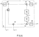
Fig. 6 schliesslich zeigt eine digitale Variante des Feedback-Prinzips. Das Eingangssignal s(t) resp. das Ausgangssignal y(t) der Verstärkerschaltung 1 werden jeweils von einem A/D-Wandler 50 resp. 58 abgetastet und digitalisiert. Analog zu Fig. 5 wird das digitale Eingangssignal sm(i) in einem einstellbaren Verzögerungsglied 52 entsprechend der ermittelten Durchlaufszeit td(i) verzögert und mit dem linearen Koeffizienten k₁(i) verstärkt (Multiplizierer 53). Das so aufbereitete Eingangssignal wird vom digitalisierten Ausgangssignal ym subtrahiert (Summierglied 54). Das resultierende (digitale) Differenzsignal em(i) wird in einem FFT-Rechner 55 einer schnellen Fouriertransformation unterworfen:
Der Fehlersignalgenerator 56 erzeugt das gewünschte Fehlersignal cm(i):
The
Dieses wird auf digitaler Ebene zum Eingangssignal sm hinzuaddiert (Summierglied 57). Das so vorverzerrte Signal wird mit einem D/A-Wandler 51 zum Eingangssignal x(t) der Verstärkerschaltung 1 gemacht.This is added to the input signal s m on a digital level (summing element 57). The signal predistorted in this way is made with a D /
Die erfindungsgemässe Identifikation und die Kompensation (Vorverzerrung) können auch für sich allein verwendet werden. D.H. die Vorverzerrung kann durchaus auf der Basis einer andersartigen Identifikation erfolgen, sofern letztere die gewünschten Koeffizienten und Durchlaufszeiten liefert. Dabei ist insbesondere auf die eingangs erwähnte, frühere Anmeldung zu verweisen, die das Verstärkersignal auf der Grundlage einer bestimmten, aber näherungsweise infinitesimal kleinen Durchlaufszeit kompensiert. Aus den für den Fachmann eindeutigen Parallelen (Identifikation - Kompensation) können daher weiter Ausführungsformen ohne erfinderisches Zutun kombiniert werden.The identification according to the invention and the compensation (predistortion) can also be used alone. D.H. the predistortion can certainly be based on a different type of identification, provided the latter provides the desired coefficients and processing times. In particular, reference should be made to the earlier application mentioned at the outset, which compensates for the amplifier signal on the basis of a specific, but approximately infinitesimally short throughput time. From the parallels which are clear to the person skilled in the art (identification - compensation), further embodiments can therefore be combined without inventive intervention.
Abschliessend kann festgestellt werden, dass die Erfindung die Linearisierung von nichtlinearen Kennlinien ermöglicht, wie sie insbesondere bei Hochleistungsverstärkern in der Nachrichtentechnik benötigt werden.In conclusion, it can be stated that the invention enables the linearization of non-linear characteristic curves, as are required in particular in the case of high-performance amplifiers in communications technology.
Claims (10)


oder
Kc = geeignet vorgegebene Konstante,
und das Kompensationssignal c(t) unter Verwendung der schnellen Fouriertransformation aus den Fourierkoeffizienten Cn(i) erzeugt wird.A method according to claim 3, characterized in that the Fourier coefficients C n (i) of the additive compensation signal c (t) according to the relationship
or
K c = suitably given constant,
and the compensation signal c (t) is generated from the Fourier coefficients C n (i) using the fast Fourier transform.


eines Steuerintervalls (i) unter Verwendung der ermittelten Koeffizienten k₁(i), ..., kL(i) nach der Methode der kleinsten Fehlerquadrate bestimmt wird.A method according to claim 5, characterized in that for the adaptive determination of the throughput time t d (i) the 2N equations
a control interval (i) is determined using the determined coefficients k₁ (i), ..., k L (i) according to the least squares method.
Priority Applications (1)
| Application Number | Priority Date | Filing Date | Title |
|---|---|---|---|
| EP19910106653 EP0513402A1 (en) | 1991-04-24 | 1991-04-24 | Method of compensating for non-linearities in an amplifying circuit with strong signal passage time |
Applications Claiming Priority (1)
| Application Number | Priority Date | Filing Date | Title |
|---|---|---|---|
| EP19910106653 EP0513402A1 (en) | 1991-04-24 | 1991-04-24 | Method of compensating for non-linearities in an amplifying circuit with strong signal passage time |
Publications (1)
| Publication Number | Publication Date |
|---|---|
| EP0513402A1 true EP0513402A1 (en) | 1992-11-19 |
Family
ID=8206658
Family Applications (1)
| Application Number | Title | Priority Date | Filing Date |
|---|---|---|---|
| EP19910106653 Withdrawn EP0513402A1 (en) | 1991-04-24 | 1991-04-24 | Method of compensating for non-linearities in an amplifying circuit with strong signal passage time |
Country Status (1)
| Country | Link |
|---|---|
| EP (1) | EP0513402A1 (en) |
Cited By (4)
| Publication number | Priority date | Publication date | Assignee | Title |
|---|---|---|---|---|
| WO1996031946A2 (en) * | 1995-04-05 | 1996-10-10 | Nokia Telecommunications Oy | A linearizer for linearizing a non-linear component controlled by control voltage |
| WO2001003287A1 (en) * | 1999-06-30 | 2001-01-11 | Wireless Systems International Limited | Reducing distortion of signals |
| WO2001031778A1 (en) * | 1999-10-26 | 2001-05-03 | Telefonaktiebolaget Lm Ericsson (Publ) | Adaptive linearization of power amplifiers |
| EP1152525A2 (en) * | 2000-05-01 | 2001-11-07 | Sony Corporation | Distortion-compensating apparatus |
-
1991
- 1991-04-24 EP EP19910106653 patent/EP0513402A1/en not_active Withdrawn
Non-Patent Citations (4)
| Title |
|---|
| IEEE INTERNATIONAL CONFERENCE ON COMMUNICATIONS BOSTONICC/89 WORLD PROSPERITY THROUGH COMMUNICATIONS SHERATON BOSTON HOTEL Bd. 1, 11. Juni 1989, BOSTON,MA Seiten 286 - 291; G. KARAM ET AL: 'Improved Data Predistortion Using Intersymbol Interpolation' * |
| IEEE INTERNATIONAL CONFERENCE ON COMMUNICATIONS BOSTONICC/89 WORLD PROSPERITY THROUGH COMMUNICATIONS SHERATON BOSTON HOTEL Bd. 3, 11. Juni 1989, BOSTON,MA Seiten 1468 - 1472; R.BLUM ET AL: 'Modeling Nonlinear Amplifiers for Communication Simulation' * |
| PATENT ABSTRACTS OF JAPAN vol. 12, no. 499 (P-807)27. Dezember 1988 & JP-A-63 208 913 ( SHINKEN K.K. ) 30. August 1988 * |
| PROCEEDINGS OF THE IEEE. Bd. 76, Nr. 10, Oktober 1988, NEW YORK US Seiten 1383 - 1385; J.C. LEE S.K. MITRA: 'On The Block Least Squares Adaptive Digital Filters Realized Using the Fast Fourier Transform' * |
Cited By (10)
| Publication number | Priority date | Publication date | Assignee | Title |
|---|---|---|---|---|
| WO1996031946A2 (en) * | 1995-04-05 | 1996-10-10 | Nokia Telecommunications Oy | A linearizer for linearizing a non-linear component controlled by control voltage |
| WO1996031946A3 (en) * | 1995-04-05 | 1996-12-27 | Nokia Telecommunications Oy | A linearizer for linearizing a non-linear component controlled by control voltage |
| US5847604A (en) * | 1995-04-05 | 1998-12-08 | Nokia Telecommunications Oy | Linearizer for linearizing a non-linear component controlled by control voltage |
| WO2001003287A1 (en) * | 1999-06-30 | 2001-01-11 | Wireless Systems International Limited | Reducing distortion of signals |
| US7106806B1 (en) | 1999-06-30 | 2006-09-12 | Andrew Corporation | Reducing distortion of signals |
| WO2001031778A1 (en) * | 1999-10-26 | 2001-05-03 | Telefonaktiebolaget Lm Ericsson (Publ) | Adaptive linearization of power amplifiers |
| US6246286B1 (en) | 1999-10-26 | 2001-06-12 | Telefonaktiebolaget Lm Ericsson | Adaptive linearization of power amplifiers |
| JP2003513498A (en) * | 1999-10-26 | 2003-04-08 | テレフオンアクチーボラゲット エル エム エリクソン(パブル) | Adaptive linearization of power amplifiers |
| EP1152525A2 (en) * | 2000-05-01 | 2001-11-07 | Sony Corporation | Distortion-compensating apparatus |
| EP1152525A3 (en) * | 2000-05-01 | 2006-08-16 | Sony Corporation | Distortion-compensating apparatus |
Similar Documents
| Publication | Publication Date | Title |
|---|---|---|
| EP0465709A1 (en) | Method for compensating the nonlinear distortions of an amplifier | |
| DE60006102T2 (en) | BROADCASTING TRANSMISSION SYSTEM WITH DISTRIBUTED CORRECTION | |
| DE69718304T2 (en) | ADAPTIVE DISTORTION COMPENSATION CIRCUIT FOR AMPLIFIERS | |
| DE602005006119T2 (en) | Editing method for configuration data of a telecommunication system and computer product and server therefor | |
| EP0656737B1 (en) | Hearing aid with cancellation of acoustic feedback | |
| DE69934930T2 (en) | Device with a power amplifier with a feedforward linearizer using a tracking algorithm | |
| EP0243898B1 (en) | Circuit for series compensation of amplifier non-linearities | |
| DE2019104B2 (en) | AMPLIFIER FOR ELECTRIC SIGNALS | |
| DE69929964T2 (en) | ADAPTIVE VOLTAGE ADJUSTMENT IN A POWER AMPLIFIER | |
| DE60014175T2 (en) | METHOD AND DEVICE FOR COMPENSATING NON-LINEARITIES AND TIME VARIANTS CHANGING A TRANSFER FUNCTION EFFECTIVELY TO AN INPUT SIGNAL | |
| DE2143707C3 (en) | Low distortion electrical signal amplifier with feedforward | |
| DE2850289A1 (en) | SIGNAL GENERATOR FOR THIRD HARMONICS | |
| DE60313036T2 (en) | SIGNAL ADJUSTMENT BASED ON PHASE FAULT | |
| EP0513402A1 (en) | Method of compensating for non-linearities in an amplifying circuit with strong signal passage time | |
| DE2412031C3 (en) | Push-pull amplifier | |
| DE19824171B4 (en) | A method and processing system for iteratively updating the coefficients of an adaptive filter | |
| DE2719873C2 (en) | Circuit arrangement for feeding in a compensation voltage | |
| DE10296941T5 (en) | Method and device for correcting signal distortion | |
| DE102005020318B4 (en) | Method for determining a model for an electrical network and use of the method | |
| DE1499327A1 (en) | Computer system | |
| DE60306619T2 (en) | IMPROVEMENT IN OR FOR PERFORMANCE AMPLIFIERS | |
| DE2847098B2 (en) | Correction circuit arrangement for a semiconductor amplifier connected to a signal input | |
| EP0884837B1 (en) | Circuitry comprising differential amplifying stages | |
| EP1219025B1 (en) | Method for linearising a high-frequency amplifier | |
| DE69727784T2 (en) | Radio frequency amplifier |
Legal Events
| Date | Code | Title | Description |
|---|---|---|---|
| PUAI | Public reference made under article 153(3) epc to a published international application that has entered the european phase |
Free format text: ORIGINAL CODE: 0009012 |
|
| AK | Designated contracting states |
Kind code of ref document: A1 Designated state(s): AT BE CH DE DK ES FR GB GR IT LI LU NL SE |
|
| RBV | Designated contracting states (corrected) |
Designated state(s): DE FR GB |
|
| 17P | Request for examination filed |
Effective date: 19930429 |
|
| RAP1 | Party data changed (applicant data changed or rights of an application transferred) |
Owner name: THOMCAST AG |
|
| RIN1 | Information on inventor provided before grant (corrected) |
Inventor name: PURI, NARINDRA NATH, PROF.DR. |
|
| STAA | Information on the status of an ep patent application or granted ep patent |
Free format text: STATUS: THE APPLICATION IS DEEMED TO BE WITHDRAWN |
|
| 18D | Application deemed to be withdrawn |
Effective date: 19951101 |