EP0536554A1 - Method and apparatus for reducing system overhead for a touch screen device - Google Patents
Method and apparatus for reducing system overhead for a touch screen device Download PDFInfo
- Publication number
- EP0536554A1 EP0536554A1 EP92115547A EP92115547A EP0536554A1 EP 0536554 A1 EP0536554 A1 EP 0536554A1 EP 92115547 A EP92115547 A EP 92115547A EP 92115547 A EP92115547 A EP 92115547A EP 0536554 A1 EP0536554 A1 EP 0536554A1
- Authority
- EP
- European Patent Office
- Prior art keywords
- pointing device
- timer
- points
- motion
- delay period
- Prior art date
- Legal status (The legal status is an assumption and is not a legal conclusion. Google has not performed a legal analysis and makes no representation as to the accuracy of the status listed.)
- Granted
Links
Images


Classifications
-
- G—PHYSICS
- G06—COMPUTING; CALCULATING OR COUNTING
- G06F—ELECTRIC DIGITAL DATA PROCESSING
- G06F3/00—Input arrangements for transferring data to be processed into a form capable of being handled by the computer; Output arrangements for transferring data from processing unit to output unit, e.g. interface arrangements
- G06F3/01—Input arrangements or combined input and output arrangements for interaction between user and computer
- G06F3/03—Arrangements for converting the position or the displacement of a member into a coded form
- G06F3/033—Pointing devices displaced or positioned by the user, e.g. mice, trackballs, pens or joysticks; Accessories therefor
- G06F3/0354—Pointing devices displaced or positioned by the user, e.g. mice, trackballs, pens or joysticks; Accessories therefor with detection of 2D relative movements between the device, or an operating part thereof, and a plane or surface, e.g. 2D mice, trackballs, pens or pucks
-
- G—PHYSICS
- G06—COMPUTING; CALCULATING OR COUNTING
- G06F—ELECTRIC DIGITAL DATA PROCESSING
- G06F3/00—Input arrangements for transferring data to be processed into a form capable of being handled by the computer; Output arrangements for transferring data from processing unit to output unit, e.g. interface arrangements
- G06F3/01—Input arrangements or combined input and output arrangements for interaction between user and computer
- G06F3/03—Arrangements for converting the position or the displacement of a member into a coded form
- G06F3/033—Pointing devices displaced or positioned by the user, e.g. mice, trackballs, pens or joysticks; Accessories therefor
- G06F3/038—Control and interface arrangements therefor, e.g. drivers or device-embedded control circuitry
-
- G—PHYSICS
- G06—COMPUTING; CALCULATING OR COUNTING
- G06F—ELECTRIC DIGITAL DATA PROCESSING
- G06F3/00—Input arrangements for transferring data to be processed into a form capable of being handled by the computer; Output arrangements for transferring data from processing unit to output unit, e.g. interface arrangements
- G06F3/01—Input arrangements or combined input and output arrangements for interaction between user and computer
- G06F3/048—Interaction techniques based on graphical user interfaces [GUI]
- G06F3/0487—Interaction techniques based on graphical user interfaces [GUI] using specific features provided by the input device, e.g. functions controlled by the rotation of a mouse with dual sensing arrangements, or of the nature of the input device, e.g. tap gestures based on pressure sensed by a digitiser
- G06F3/0488—Interaction techniques based on graphical user interfaces [GUI] using specific features provided by the input device, e.g. functions controlled by the rotation of a mouse with dual sensing arrangements, or of the nature of the input device, e.g. tap gestures based on pressure sensed by a digitiser using a touch-screen or digitiser, e.g. input of commands through traced gestures
- G06F3/04883—Interaction techniques based on graphical user interfaces [GUI] using specific features provided by the input device, e.g. functions controlled by the rotation of a mouse with dual sensing arrangements, or of the nature of the input device, e.g. tap gestures based on pressure sensed by a digitiser using a touch-screen or digitiser, e.g. input of commands through traced gestures for inputting data by handwriting, e.g. gesture or text
Definitions
- This invention generally relates to input devices for a data processing system and, more particularly, a method and apparatus for reducing system overhead associated with distinguishing between input signals generated by different types of pointing devices.
- the invention has particular application in a multi-tasking computer system in which a single task is dedicated to controlling a timer used to distinguish between the input signals.
- U.S. Patent No. 5,025,411 discloses a typical input device in the form of a touch screen used to control the operation of a digital oscilloscope.
- U.S. Patent No. 4,587,630 discloses a programmable touch screen emulating a keyboard input device.
- U.S. Patent No. 4,903,012 discloses a touch screen for calibrating the coordinates of a computer system. Such devices are designed to allow an unsophisticated user to perform desired tasks on a computer system without extensive training. Human factor studies have shown that an input device which allows the user to input data directly on the computer display achieves greatest immediacy and accuracy between man and machine.
- U.S. Patent No. 4,886,941 and Japanese Publications Nos. 62-80724 and 63-311426 describe prior art systems employing mouse-pointing devices as input devices for data processing systems. Some advanced softward applications allow a user to input complex control signals with a finger.
- U.S. Patent No. 4,899,138 discloses a touch panel for providing control signals in accordance with the manner in which a finger touches the panel within a predetermined period of time (i.e., making a gesture).
- a stylus has proven to be more effective in inputting information on a touch sensitive input device because of its greater precision. It is more convenient to utilize a touch input system which allows both a stylus and a finger to operate as input devices.
- One such system is described in commonly assigned U.S. Patent No. 4,686,332, entitled “Combined Finger Touch and Stylus Detection System for Use on the Viewing Surface of a Visual Display Device,” and which is hereby expressly incorporated herein by reference.
- a touch input device for a data processing system
- input signals generated from a pointing device can be categorized either as a mouse input signal or as a gesture or handwriting input signal.
- input signals are intended to emulate the behavior of a mouse and represent commands, such as mouse button down and mouse button up, the stylus or finger is respectively touched down and lifted off the surface.
- the input device allows the user to use a stylus and touch sensor to simulate pen and paper to create a handwriting input signal, alphanumeric characters can be entered into an appropriate application program.
- a series of such input signals resembling a geometric figure, such as a circle, a right-hand or a left-hand arrow, are indicative of an action to be taken by the computer system.
- a geometric figure such as a circle, a right-hand or a left-hand arrow
- One method of differentiating between the types of input signals is by timing. If the user, after initiating contact between a pointing device and the touch sensor, moves the pointing device to a desired position and stops motion for a predetermined time period without losing contact between the device and the touch sensor (hereinafter referred to as "lift-off"), the operating system will recognize an input signal at the desired position as a mouse command. For example, if the user stops moving the pointing device at a given position for 200 milliseconds, a mouse command at the given position is recognized. If, on the other hand, the user does not stop at any given position for the specified time delay period and instead lifts off the touch sensor, the input signals are selected as candidates for character or gesture recognition instead of mouse commands.
- the operating system To detect the cessation of motion at a desired position, the operating system repeatedly resets a delay software timer each time a position point identified by an input signal generated by the pointing device is sufficiently offset from a previous position point. Repeatedly resetting the timer in this manner creates a large amount of processing overhead when the cessation detection is required in a multi-tasking system.
- a multi-tasking computer system creates the illusion of concurrently running a plurality of computer processes, also known as jobs, tasks or threads. To create this illusion, an operating system switches a single processor between multiple threads.
- a timer thread is dedicated to managing the software timer. The timer thread cannot reset the timer until the processor saves all computations made while executing the current thread and switches back to the timer thread. As a result, a large amount of processing time is required to repeatedly reset the above-described timer.
- a delay timer in an operating system of a computer receiving input from a pointing device.
- the identity of the pointing device is established, and the rate at which points (represented by the input signals) are generated by the pointing device is determined.
- a timer reset divide rate is calculated such that the delay timer is reset on every nth point generated, even though motion of the pointing device may have been detected on the current point. Points are collected as the pointing device is moved across a touch-sensitive computer display.
- points are collected from a pointing device that causes a cursor to move across a display screen without requiring the screen to be touched by the pointing device, e.g., mouse, joystick, etc.
- the timer is reset with a predetermined time-delay period. If motion has occurred within the previous n points, but has ceased during the generation of the last several points, the timer is reset with an additional amount of time attributable to such last several points in order to maintain the accuracy of the timing. If it is determined that the motion of the pointing device ceased for the predetermined time-delay period, e.g., 200 milliseconds, an action is performed by the computer system.
- the predetermined time-delay period e.g. 200 milliseconds
- the action is a mouse command, such as a mouse button down or mouse button up, that is generated at the point where motion ceased. If the pointing device does not stop at any position for the predetermined time-delay period, but instead lifts off, the set of points generated by the pointing device is sent to a character- or gesture-recognition unit as candidates for character or gesture recognition.
- a given point is generated from the pointing device and marked as a reference point.
- Each subsequently generated point is monitored with respect to a time period relative to the time the reference point was generated.
- the delay timer is reset as in the embodiment above.
- Fig. 1 shows a touch workpad substantially similar to that described in European Patent Application 90 108 082.0.
- the workpad 10 comprises a housing 12 having a rectangular recessed window 14 which surrounds the edges of a rectangular touch overlay 16.
- the touch overlay 16 is transparent and is disposed on a liquid crystal display (LCD) 18.
- the overlay 16 consists of a laminate structure including several plastic substrate layers laminated together by means of adhesive layers.
- the overlay 16 also includes a first plurality of transparent X conductors 16A disposed in the vertical direction and a second plurality of transparent Y conductors 16B disposed in the horizontal direction. Several of the conductors in both the vertical and horizontal directions are positioned beyond the recessed window 14 to allow more accurate determination of the location of the stylus 20 or a finger on or near the overlay 16 at the edges of the display window 14.
- the stylus 20 is connected to the touch workpad via cable 22.
- the stylus 20 acts as an antenna to pick up the signals radiated by the overlay 16, and provides much greater resolution than can be provided by a finger touch.
- Also on the bezel of the housing are four button switches 24-27 which can be used to change the mode in which the data from the workpad 10 is received.
- Workpad cable 28 connects the workpad 10 to the computer with which the user is communicating.
- the workpad cable 28 provides power to the workpad 10 as well as display signals to operate the LCD 18 and also touch signals to operate the overlay in both finger touch and stylus modes.
- the cable 28 is also the conduit to the computer for the measurement of the signal strength received by the stylus 20 and of the frequency change due to changes in capacitance of a finger touch.
- Fig. 2 shows an architectural diagram of the finger touch and stylus detection system which is similar to that disclosed in Fig. 9 of U.S. Patent No. 4,686,332.
- the touch control processor 30, random access memory 32, read only memory and the I/O controller 36 are on a touch panel adapter card 37 in a personal computer, while the rest of the touch electronics are integrated in the touch workpad 10.
- the touch workpad 10 communicates with the personal computer and touch panel adapter card 37 via the workpad cable 28.
- the vertical X conductors and the horizontal Y conductors are connected through the X bus 38 and the Y bus 40, respectively, to the wire selection multiplexer 42.
- the radiative pickup stylus 20 is connected through the gate 44 to the radiative pickup measurement device 46.
- the wire selection multiplexer 42 is connected through the mode multiplexer 50 to the capacitance measurement device 52 which is used for capacitance finger touch detection.
- the wire selection multiplexer 42 is also connected through the mode multiplexer 50 to the 40 kHz oscillator driver 54 which is used to drive the X bus 38 and the Y bus 40 for the stylus detection operation.
- the mode multiplexer 50 also provides an enabling input to the gate 44 to selectively connect the output of the stylus 20 to the radiative pickup measurement device 46 for stylus detection operations.
- the output of the capacitance measurement device 52 is connected through the analog-to-digital converter 56 to the workpad bus 58.
- the output of the radiative pickup measurement device 46 is connected through the analog-to-digital converter 48 to the bus 58.
- the control input 60 of the wire selection multiplexer 42 is connected to the bus 58.
- the control input 62 of the mode multiplexer 50 also is connected to the bus 58.
- the workpad bus 58 is connected via workpad interface 64 to the workpad cable 28 which is connected to interface 66 in the touch panel adapter card 37 of the personal computer (PC).
- the PC interface 66 communicates with the main system bus 68 and with the adapter card 70.
- the I/O controller 36 has an I/O bus 72 which is connected to the main bus 68 of the PC.
- the I/O controller 36 is also connected to adapter card bus 70.
- the adapter bus 70 also interconnects the control processor 30 with the read only memory (ROM) 34 and the random access memory (RAM) 32.
- the personal computer includes standard devices known in the art such as a CPU 74, ROM 76, disk storage 78, a memory 80 which stores operating system 81 and application programs 82, a standard keyboard 84, and a standard display 86.
- the standard display 86 is typically a cathode ray tube (CRT), and in the preferred embodiment the display 86 is in addition to the liquid crystal display (LCD) 18 of workpad 10.
- the wire selection multiplexer 42 and the mode multiplexer 50 connect selected patterns of a plurality of the horizontal and vertical conductors in the overlay 16 to either the capacitance measurement device 52 or the 40 kHz oscillator driver 54, in response to control signals applied over the control inputs 60 and 62 from the bus 58 by the control processor 30.
- the capacitance measuring device 52 has its input coupled through the mode multiplexer 50 and the wire selection multiplexer 42 to selected single conductors in the horizontal and vertical conductor array in the overlay 16 in response to control signals from the control processor 30.
- the output of the capacitance measurement device 52 is converted to digital values by the A/D converter 56 and is supplied over the bus 58 to the control processor 30.
- the control processor 30 executes a sequence of stored program instructions to detect the horizontal array conductor pair and the vertical array conductor pair in the overlay 16 which are both being touched by the operator's finger.
- the finger touch and stylus sensing modes operate independently of one another, the detection system cycling between the two modes until a finger touch or stylus is detected.
- European Patent Application 90 101 292.2 an operating system extension is described which allows alternative forms of input to be handled by conventional software applications which were not written to understand such alternative forms of input. For example, conventional applications are written to accept only keyboard and mouse input signals. A user could use the Advanced User Interface (AUI) to utilize a touch sensor without modifying any of the software application code.
- AUI is stored in RAM 80 with the operating system 81 and application programs 82. In a preferred embodiment, this invention improves AUI by allowing it more efficiently to distinguish between mouse commands and gesture or character data.
- Fig. 3 is a representation of the touch workpad of Fig. 1 showing an opened software application window 100.
- the application is called "MAG.EXE.”
- the work space area 102 is a typical feature of a window and is the area where most data for input of the application is generated.
- the action bar 104 contains a single selectable menu item, "options.” If the user touches down with the pointing device (e.g., stylus, finger, etc.) on the "options" menu item, a pulldown menu will appear to allow him to select one of many available options.
- the pointing device e.g., stylus, finger, etc.
- the window also depicts the inked trail of a set of points representing a gesture 106 made by a pointing device.
- the gesture 106 is an "up arrow" which is one of many gestures which is recognizable by the AUI and which a user can use to cause the computer system to take one of many possible actions.
- One possible meaning for the "up arrow" gesture when input in the work space area 102 of window 100, would be to enlarge or to maximize the window 100.
- a long line 107 representing another trail of input points generated by a pointing device.
- the user moved twelve points and then ceased further movement.
- the user did not move the pointing device from point 12 to point 35.
- a timeout was created and program execution transferred to mouse emulation mode.
- an application command such as a "file” command 108, could be activated by recognizing the series of points as a "file” command generated by a mouse-pointing device and sent to the application program.
- the present invention includes a computer module within the stylus or finger-based operating system extension (AUI) to differentiate between touch input signals intended to emulate a mouse command, such as a mouse button down, mouse move, or a mouse button up, and those touch input signals which are to be considered a gesture or character.
- This differentiation is done by using a time delay to differentiate between the two types of touch input signals.
- the AUI allows the user to touch the screen and move to the desired position before the application is notified of the command by placing all the points received from the touch sensor in a stroke buffer.
- the points stored in the stroke buffer are hereinafter referred to as "a stroke.”
- the stroke buffer is not used and the application is passed a mouse command; in the preferred embodiment the command would be a mouse button down message.
- a mouse command such as a mouse up button command
- the command is not generated until the user once again stops (without lifting off) and pauses for the period of time delay.
- the time delay is typically defined in milliseconds (ms) and may be varied depending upon the screen area with which the user is interacting. The time delay may be specified by the user or may be altered by the application program which is utilizing the touch input signal.
- the AUI selects the set of input points generated by the pointing device (the stroke) as candidate points for character or gesture recognition.
- the time delay provides a window in time in which gestures can be made. During this time, the AUI will only allow gestures to be made. If the user waits for the time delay period before lifting off, the points generated by the pointing device will not be candidates for a gesture.
- the stopping point coordinates i.e., coordinates corresponding to the last point generated by the pointing device prior to detection of motion cessation) are then used for a mouse command.
- a user having determined that he wishes to invoke a software utility by making a gesture with a pointing device, draws a circle on the face of the touch sensor 16 and lifts the device off before the end of the set time delay.
- the touch sensor 16 generates a series of interrupts to a device driver for the touch workpad at 110 which passes a set of input signals to the AUI corresponding to the set of points in the circle at 112.
- the AUI When the AUI discovers the first touch input point (i.e., a touch-down of the pointing device on the touch sensor 16), it looks up the time delay period selected by the user or programmer at 120. At 122, the touch input points generated by the pointing device are collected in a stroke buffer until the stylus lift-off event is detected. At 124, as the touch input points are received by the AUI. A delay timer is reset every nth point to determine the period of stability or cessation of pointing device movement initiated by the user pausing on the touch sensor at 126. If the user moves the pointing device before the time delay period has expired, the AUI continues to receive the touch input points in the stroke buffer at 122.
- a mouse command is recognized and generated at 130.
- the user does not pause before pointing device (e.g., the stylus 20) is lifted, and therefore, the stroke is sent to a character recognition unit or gesture recognition unit for processing at 128. If the touch input stroke has not been recognized as either a gesture or character, a mouse command would be generated at 130.
- the AUI passes the circle gesture signal to the appropriate computer module 132.
- the user first touches a pointing device down on the touch sensor in 150 and generates one point.
- the pointing device that generated that point is identified; that is, the pointing device is identified as a finger, stylus, mouse, etc.
- the point generation rate is determined.
- Each pointing device generates points at different rates.
- the stylus for example, generates 110 points per second, whereas the mouse generates 40 points per second.
- the system refers to a user profile and retrieves a delay timer value. There is a different delay timer value for each pointing device. For example, the stylus timer delay is 200 ms, whereas the finger timer delay is 300 ms.
- the delay timer value is divided by 2.3, an empirically derived constant, to yield 86 ms (i.e., 200 ms divided by 2.3 yields 86 ms).
- the number of points expected during this 86 ms period is then calculated. With a stylus generating 110 points per second, there would be approximately 9 input points during the 86 ms period.
- the system records the touch-down point and uses it as an anchor.
- the term "anchor" implies that the next point generated by the pointing device must be a predetermined distance from the touch-down point to be considered a movement of the pointing device. The predetermined distance may be varied in accordance with the system resolution.
- the point count is zeroed out. As the points are received, they are counted.
- the delay timer is started using the retrieved value. At this point, setup initialization is completed.
- the user lifts the pointing device off the touch sensor. If the user lifts off, there will be no mouse emulation detected and the system categorizes the input points generated by the pointing device as a gesture or handwriting input and cancels the timer.
- the delay timer times out. The delay timer timed out because the user stopped moving the pointing device for time in excess of the delay period and the system stopped resetting the timer. When that happens, the system enters mouse emulation mode.
- each new point generated is collected from the touch sensor.
- the points are received at 110 points per second.
- the point count is incremented.
- the X - Y coordinates of the newest input point are examined to see if the point is more than two picture elements (pels) from the anchor or the previous input point. If so, the system classifies the pointing device as having movement.
- the new point is recorded. The X-Y coordinates are used for the new anchor, and the timestamp of that point is saved. If there is no movement, the last two steps are omitted.
- the number of points received up to this time is calculated.
- the system proceeds to 180 to see if motion had occurred within the last n points. ("n" in this case is 9.)
- the divide rate for the stylus would be 9, so the system would check for multiples of 9 (e.g., 9, 18, 27, etc.). If motion has occurred, the elapsed time is determined from the time the last motion point was received. If there has been any elapsed time since the last motion point, the elapsed time is subtracted from the original timer value, e.g., 200 ms. At 186, the timer delay is reset using the new timeout value which would be 200 ms minus the elapsed time between motion cessation and the nth point. In 178 and 180, if either of those tests resulted in no, the system exits.
- Fig. 6 there is shown a stroke consisting of a touch-down and a series of nine (9) points.
- 9 points are received from the stylus, the system checks to see if movement has occurred within the last 9 points.
- the stylus movement has been relatively rapid. In actual use, the points are likely to be spaced more closely together.
- Fig. 6 there has been motion within the last 9 points; the portion of the stroke from point 8 to point 9 has been inked.
- the delay timer which is waiting for a period of stability of 200 ms, is reset to zero and resumes waiting for the user to stop moving.
- Fig. 7 the user has continued to move on to points 10, 11 and 12.
- Points 13-18 are shown in parenthesis. After the user moved to point 12, he held the stylus stationary so that the last 6 points were generated in the same position as the 12th point.
- the system again, determines if any motion occurred in the previous 9 points. Again, the answer is yes. Motion occurred on the first 3 points (10-12). However, on the last 6 points there was no motion, so the 200 ms timer is reset. To account for the absence of motion for the last 6 points, probably 50 ms, the timer is reset at the value of 200 ms minus 50 ms which equals 150 ms.
- Fig. 8 shows that the user never did again move the stylus.
- the stylus remained stationary after point 12, and points 19-35 show there was no movement so the timer is never reset.
- a timeout occurred because the user failed to move the pointing device for 200 ms.
- mouse emulation mode is entered to cause a mouse command input message to be produced.
- the AUI system provides facilities for finger- and stylus-based user interface devices. When used with devices capable of tracking the movement of a user's finger or the movement of a stylus, AUI provides support for the handling of the resulting stroke information. These facilities include the visual tracing on the screen of ink flowing from the stylus, the delivery of the stroke information to application programs, and the delivery of the stroke information to recognition subsystems for further analysis.
- AUI employs a user interface technique where mouse emulation for the pointing device (stylus, finger or mouse) is delayed until the user stops moving the pointing device. Any stroke completed (i.e., pointing device is lifted off touch sensor) before movement has stopped is classified as a gesture or handwriting input. After motion stops, it is assumed the user intends to emulate a mouse input, and a mouse emulation mode begins. To effect the detection of motion cessation, the user must touch down and hold the pointing device stationary for a timeout period. "Stationary" is defined as no change in position greater than n pels, where 'n pels' can be expressed in either display or sensor resolution units. In one preferred embodiment, a value of two display pels is used.
- Examples of typical timeout values are 200 ms for a stylus, 300 ms for finger touch, and 200 ms for a mouse. These values represent a trade-off between minimizing the delay to enter mouse emulation and making gestures easy to stroke without inadvertently timing out during the stroke.
- the invention has particular application in a multi-tasking computer system.
- a single task or thread is typically dedicated to managing a delay timer used to determine motion cessation.
- a stylus pointing device generates 110 points per second, one point every 9 ms.
- the prior art processor would need to switch to and from the timer thread every 9 ms when the stylus is in motion. As a result, 100% of the processing time of the system is taken up by managing the timer, assuming the processor takes 9 ms to process data for each point generated.
- this timer thread needs to be reset only every nth point generated by the pointing device used with the computer system.
- the system processor does not have to waste processing time to switch between a currently executing thread to the timer thread after each point is generated by a moving pointing device.
- the timer can be reset periodically at timed intervals, e.g., 86 ms, in accordance with the following alternative embodiment of the invention.
- an initial point generated by the pointing device is used as an anchor point (as in the embodiment described above). All subsequent points are then monitored as to their time period of generation (hereinafter referred to as a "timestamp") relative to the anchor point was generated.
- a timer is reset and the point is used as the new anchor point.
- the timer is periodically reset at given time intervals when points are generated within the predetermined time-delay period, e.g., 200 ms. If no points are generated by the pointing device, and no movement thereof is detected, then a timeout occurs and a the system enters a mouse emulation mode (as described above).
Abstract
Description
- This invention generally relates to input devices for a data processing system and, more particularly, a method and apparatus for reducing system overhead associated with distinguishing between input signals generated by different types of pointing devices. The invention has particular application in a multi-tasking computer system in which a single task is dedicated to controlling a timer used to distinguish between the input signals.
- The use of a touch input device disposed over the viewing surface of a computer display to provide a "user friendly" means for the control of a data processing system is well known in the art. U.S. Patent No. 5,025,411 discloses a typical input device in the form of a touch screen used to control the operation of a digital oscilloscope. U.S. Patent No. 4,587,630 discloses a programmable touch screen emulating a keyboard input device. U.S. Patent No. 4,903,012 discloses a touch screen for calibrating the coordinates of a computer system. Such devices are designed to allow an unsophisticated user to perform desired tasks on a computer system without extensive training. Human factor studies have shown that an input device which allows the user to input data directly on the computer display achieves greatest immediacy and accuracy between man and machine.
- In current graphical user interfaces developed to aid man-machine interaction, there are many items, such as menu selections, icons or windows, which a user can most easily select by using a mouse or a finger. U.S. Patent No. 4,886,941 and Japanese Publications Nos. 62-80724 and 63-311426 describe prior art systems employing mouse-pointing devices as input devices for data processing systems. Some advanced softward applications allow a user to input complex control signals with a finger. U.S. Patent No. 4,899,138, for example, discloses a touch panel for providing control signals in accordance with the manner in which a finger touches the panel within a predetermined period of time (i.e., making a gesture).
- A stylus has proven to be more effective in inputting information on a touch sensitive input device because of its greater precision. It is more convenient to utilize a touch input system which allows both a stylus and a finger to operate as input devices. One such system is described in commonly assigned U.S. Patent No. 4,686,332, entitled "Combined Finger Touch and Stylus Detection System for Use on the Viewing Surface of a Visual Display Device," and which is hereby expressly incorporated herein by reference.
- In a touch input device (e.g., a touch workpad) for a data processing system, where a touch sensor is disposed over a viewing surface of a display, input signals generated from a pointing device, such as a stylus or finger, can be categorized either as a mouse input signal or as a gesture or handwriting input signal. Where such input signals are intended to emulate the behavior of a mouse and represent commands, such as mouse button down and mouse button up, the stylus or finger is respectively touched down and lifted off the surface. Where the input device allows the user to use a stylus and touch sensor to simulate pen and paper to create a handwriting input signal, alphanumeric characters can be entered into an appropriate application program. Where the input signal is part of a gesture, a series of such input signals resembling a geometric figure, such as a circle, a right-hand or a left-hand arrow, are indicative of an action to be taken by the computer system. As all three types of input signals may be emulated by the use of a stylus or finger as a touch input device, it would be advantageous to design a stylus- or finger-based operating system such that all three types of input signals may be simultaneously entered anywhere on the display.
- In order to utilize all three types of input signals, they must be distinguished by the data processing system. One method of differentiating between the types of input signals is by timing. If the user, after initiating contact between a pointing device and the touch sensor, moves the pointing device to a desired position and stops motion for a predetermined time period without losing contact between the device and the touch sensor (hereinafter referred to as "lift-off"), the operating system will recognize an input signal at the desired position as a mouse command. For example, if the user stops moving the pointing device at a given position for 200 milliseconds, a mouse command at the given position is recognized. If, on the other hand, the user does not stop at any given position for the specified time delay period and instead lifts off the touch sensor, the input signals are selected as candidates for character or gesture recognition instead of mouse commands.
- To detect the cessation of motion at a desired position, the operating system repeatedly resets a delay software timer each time a position point identified by an input signal generated by the pointing device is sufficiently offset from a previous position point. Repeatedly resetting the timer in this manner creates a large amount of processing overhead when the cessation detection is required in a multi-tasking system.
- A multi-tasking computer system creates the illusion of concurrently running a plurality of computer processes, also known as jobs, tasks or threads. To create this illusion, an operating system switches a single processor between multiple threads. A timer thread is dedicated to managing the software timer. The timer thread cannot reset the timer until the processor saves all computations made while executing the current thread and switches back to the timer thread. As a result, a large amount of processing time is required to repeatedly reset the above-described timer.
- It is an object of this invention to reduce the overhead associated with a delay timer which is reset each time an input signal, representing a point on a workpad, generated by a pointing device is sufficiently spaced from a previous input signal.
- It is another object of this invention to maintain the accuracy of measurement of a period of cessation of a pointing device's motion while a timer is reset on every nth position point and the pointing device has stopped sometime between timer resets.
- It is a further object of the invention to more efficiently identify an input signal generated by a pointing device in a multi-tasking computer system that dedicates a task or thread to managing a timer used to distinguish between types of input signals generated by a pointing device.
- It is also an object of the invention to reduce in a data processing system the overhead associated with a delay timer by resetting the timer periodically when a point is generated from a pointing device within a given period of time starting from the time an initial point is generated.
- These and other objects and features of the invention are accomplished by a method and apparatus which manage in the following manner a delay timer in an operating system of a computer receiving input from a pointing device. At touch-down time, the identity of the pointing device is established, and the rate at which points (represented by the input signals) are generated by the pointing device is determined. A timer reset divide rate is calculated such that the delay timer is reset on every nth point generated, even though motion of the pointing device may have been detected on the current point. Points are collected as the pointing device is moved across a touch-sensitive computer display. In the alternative, points are collected from a pointing device that causes a cursor to move across a display screen without requiring the screen to be touched by the pointing device, e.g., mouse, joystick, etc. In response to a determination that motion has occurred within the previous n points generated from the pointing device, the timer is reset with a predetermined time-delay period. If motion has occurred within the previous n points, but has ceased during the generation of the last several points, the timer is reset with an additional amount of time attributable to such last several points in order to maintain the accuracy of the timing. If it is determined that the motion of the pointing device ceased for the predetermined time-delay period, e.g., 200 milliseconds, an action is performed by the computer system. In the preferred embodiment, the action is a mouse command, such as a mouse button down or mouse button up, that is generated at the point where motion ceased. If the pointing device does not stop at any position for the predetermined time-delay period, but instead lifts off, the set of points generated by the pointing device is sent to a character- or gesture-recognition unit as candidates for character or gesture recognition.
- In another embodiment of the invention a given point is generated from the pointing device and marked as a reference point. Each subsequently generated point is monitored with respect to a time period relative to the time the reference point was generated. When subsequent point is generated at a time period greater than a given time period, the delay timer is reset as in the embodiment above.
- The above objects, features and improvements will be better understood with reference to the following drawing figures.
- Fig. 1
- shows the front view of an overlay unit used for the detection of finger touch and stylus position. The unit is disposed over a flat panel display to form what is known as a "touch workpad."
- Fig. 2
- is an architectural diagram of the combined finger touch and stylus detection system.
- Fig. 3
- is a representation of a window displayed on the touch workpad in Fig. 1 and illustrating a stroke made by a pointing device that has been recognized as a mouse command.
- Fig. 4
- is a flow diagram illustrating the operation of the present invention to distinguish between stroke input signals intended to produce mouse commands, and stroke input signals intended to produce gesture or handwriting events.
- Fig. 5A and 5B
- are flow diagrams illustrating the operation of the invention in reducing system overhead associated with resetting a delay timer to determine whether a cessation of motion has occurred.
- Fig. 6-8
- are representations of a window displayed on the touch workpad of Fig. 1 and depicting an inked stroke intended to produce a mouse command.
- Fig. 1 shows a touch workpad substantially similar to that described in European Patent Application 90 108 082.0. The
workpad 10 comprises ahousing 12 having a rectangular recessedwindow 14 which surrounds the edges of arectangular touch overlay 16. Thetouch overlay 16 is transparent and is disposed on a liquid crystal display (LCD) 18. Theoverlay 16 consists of a laminate structure including several plastic substrate layers laminated together by means of adhesive layers. - The
overlay 16 also includes a first plurality oftransparent X conductors 16A disposed in the vertical direction and a second plurality oftransparent Y conductors 16B disposed in the horizontal direction. Several of the conductors in both the vertical and horizontal directions are positioned beyond the recessedwindow 14 to allow more accurate determination of the location of thestylus 20 or a finger on or near theoverlay 16 at the edges of thedisplay window 14. - The
stylus 20 is connected to the touch workpad viacable 22. Thestylus 20 acts as an antenna to pick up the signals radiated by theoverlay 16, and provides much greater resolution than can be provided by a finger touch. Also on the bezel of the housing are four button switches 24-27 which can be used to change the mode in which the data from theworkpad 10 is received.Workpad cable 28 connects theworkpad 10 to the computer with which the user is communicating. Theworkpad cable 28 provides power to theworkpad 10 as well as display signals to operate theLCD 18 and also touch signals to operate the overlay in both finger touch and stylus modes. In addition, thecable 28 is also the conduit to the computer for the measurement of the signal strength received by thestylus 20 and of the frequency change due to changes in capacitance of a finger touch. - Fig. 2 shows an architectural diagram of the finger touch and stylus detection system which is similar to that disclosed in Fig. 9 of U.S. Patent No. 4,686,332. The
touch control processor 30,random access memory 32, read only memory and the I/O controller 36 are on a touchpanel adapter card 37 in a personal computer, while the rest of the touch electronics are integrated in thetouch workpad 10. As discussed in connection with Fig. 1, thetouch workpad 10 communicates with the personal computer and touchpanel adapter card 37 via theworkpad cable 28. The vertical X conductors and the horizontal Y conductors are connected through the X bus 38 and theY bus 40, respectively, to thewire selection multiplexer 42. Theradiative pickup stylus 20 is connected through thegate 44 to the radiativepickup measurement device 46. Thewire selection multiplexer 42 is connected through themode multiplexer 50 to thecapacitance measurement device 52 which is used for capacitance finger touch detection. Thewire selection multiplexer 42 is also connected through themode multiplexer 50 to the 40kHz oscillator driver 54 which is used to drive the X bus 38 and theY bus 40 for the stylus detection operation. Themode multiplexer 50 also provides an enabling input to thegate 44 to selectively connect the output of thestylus 20 to the radiativepickup measurement device 46 for stylus detection operations. The output of thecapacitance measurement device 52 is connected through the analog-to-digital converter 56 to theworkpad bus 58. The output of the radiativepickup measurement device 46 is connected through the analog-to-digital converter 48 to thebus 58. Thecontrol input 60 of thewire selection multiplexer 42 is connected to thebus 58. Thecontrol input 62 of themode multiplexer 50 also is connected to thebus 58. - The
workpad bus 58 is connected viaworkpad interface 64 to theworkpad cable 28 which is connected to interface 66 in the touchpanel adapter card 37 of the personal computer (PC). ThePC interface 66 communicates with themain system bus 68 and with theadapter card 70. The I/O controller 36 has an I/O bus 72 which is connected to themain bus 68 of the PC. The I/O controller 36 is also connected toadapter card bus 70. Theadapter bus 70 also interconnects thecontrol processor 30 with the read only memory (ROM) 34 and the random access memory (RAM) 32. The personal computer includes standard devices known in the art such as aCPU 74,ROM 76,disk storage 78, amemory 80 whichstores operating system 81 andapplication programs 82, astandard keyboard 84, and astandard display 86. Thestandard display 86 is typically a cathode ray tube (CRT), and in the preferred embodiment thedisplay 86 is in addition to the liquid crystal display (LCD) 18 ofworkpad 10. - The
wire selection multiplexer 42 and themode multiplexer 50 connect selected patterns of a plurality of the horizontal and vertical conductors in theoverlay 16 to either thecapacitance measurement device 52 or the 40kHz oscillator driver 54, in response to control signals applied over thecontrol inputs bus 58 by thecontrol processor 30. During finger touch operations, thecapacitance measuring device 52 has its input coupled through themode multiplexer 50 and thewire selection multiplexer 42 to selected single conductors in the horizontal and vertical conductor array in theoverlay 16 in response to control signals from thecontrol processor 30. The output of thecapacitance measurement device 52 is converted to digital values by the A/D converter 56 and is supplied over thebus 58 to thecontrol processor 30. Thecontrol processor 30 executes a sequence of stored program instructions to detect the horizontal array conductor pair and the vertical array conductor pair in theoverlay 16 which are both being touched by the operator's finger. - The finger touch and stylus sensing modes operate independently of one another, the detection system cycling between the two modes until a finger touch or stylus is detected.
- In European Patent Application 90 101 292.2 an operating system extension is described which allows alternative forms of input to be handled by conventional software applications which were not written to understand such alternative forms of input. For example, conventional applications are written to accept only keyboard and mouse input signals. A user could use the Advanced User Interface (AUI) to utilize a touch sensor without modifying any of the software application code. In accordance with the present invention, AUI is stored in
RAM 80 with theoperating system 81 andapplication programs 82. In a preferred embodiment, this invention improves AUI by allowing it more efficiently to distinguish between mouse commands and gesture or character data. - Fig. 3 is a representation of the touch workpad of Fig. 1 showing an opened
software application window 100. The application is called "MAG.EXE." Thework space area 102 is a typical feature of a window and is the area where most data for input of the application is generated. Theaction bar 104 contains a single selectable menu item, "options." If the user touches down with the pointing device (e.g., stylus, finger, etc.) on the "options" menu item, a pulldown menu will appear to allow him to select one of many available options. - The window also depicts the inked trail of a set of points representing a
gesture 106 made by a pointing device. In this case, thegesture 106 is an "up arrow" which is one of many gestures which is recognizable by the AUI and which a user can use to cause the computer system to take one of many possible actions. One possible meaning for the "up arrow" gesture, when input in thework space area 102 ofwindow 100, would be to enlarge or to maximize thewindow 100. - Also depicted in Fig. 3 is a long line 107 representing another trail of input points generated by a pointing device. For this series of points after touch-down, the user moved twelve points and then ceased further movement. As shown in Fig. 3, the user did not move the pointing device from
point 12 to point 35. Thus, a timeout was created and program execution transferred to mouse emulation mode. Now an application command, such as a "file"command 108, could be activated by recognizing the series of points as a "file" command generated by a mouse-pointing device and sent to the application program. - The present invention includes a computer module within the stylus or finger-based operating system extension (AUI) to differentiate between touch input signals intended to emulate a mouse command, such as a mouse button down, mouse move, or a mouse button up, and those touch input signals which are to be considered a gesture or character. This differentiation is done by using a time delay to differentiate between the two types of touch input signals. The AUI allows the user to touch the screen and move to the desired position before the application is notified of the command by placing all the points received from the touch sensor in a stroke buffer. The points stored in the stroke buffer are hereinafter referred to as "a stroke." Once the user reaches the desired position and stops moving for the set time delay, a mouse command is generated at the point at which the user has stopped. Since AUI recognizes the timeout as mouse emulation, rather than as a gesture command, the stroke buffer is not used and the application is passed a mouse command; in the preferred embodiment the command would be a mouse button down message. For example, if the user stops moving the pointing device at a desired position for 200 milliseconds, a mouse command, such as a mouse up button command, at the desired position is communicated to the application program. However, if the user starts to move the device again before the end of the set period of time, the command is not generated until the user once again stops (without lifting off) and pauses for the period of time delay. The time delay is typically defined in milliseconds (ms) and may be varied depending upon the screen area with which the user is interacting. The time delay may be specified by the user or may be altered by the application program which is utilizing the touch input signal.
- If, on the other hand, the user does not stop at a particular point for the specified time delay period and instead lifts off the touch screen, the AUI selects the set of input points generated by the pointing device (the stroke) as candidate points for character or gesture recognition. In other words, the time delay provides a window in time in which gestures can be made. During this time, the AUI will only allow gestures to be made. If the user waits for the time delay period before lifting off, the points generated by the pointing device will not be candidates for a gesture. The stopping point coordinates (i.e., coordinates corresponding to the last point generated by the pointing device prior to detection of motion cessation) are then used for a mouse command. If the user lifts the pointing device before the time delay period expires, an attempt will be made to recognize the set of generated points as a gesture or character. If the points are not so recognized, however, the normal mouse emulation sequence will be generated. If the points are recognized, the AUI sends the appropriate commands to the appropriate application program.
- The recognition of a circle gesture made by a pointing device on the face of the
touch overlay 16 is described below with reference to Fig. 4. - A user, having determined that he wishes to invoke a software utility by making a gesture with a pointing device, draws a circle on the face of the
touch sensor 16 and lifts the device off before the end of the set time delay. Thetouch sensor 16 generates a series of interrupts to a device driver for the touch workpad at 110 which passes a set of input signals to the AUI corresponding to the set of points in the circle at 112. - When the AUI discovers the first touch input point (i.e., a touch-down of the pointing device on the touch sensor 16), it looks up the time delay period selected by the user or programmer at 120. At 122, the touch input points generated by the pointing device are collected in a stroke buffer until the stylus lift-off event is detected. At 124, as the touch input points are received by the AUI. A delay timer is reset every nth point to determine the period of stability or cessation of pointing device movement initiated by the user pausing on the touch sensor at 126. If the user moves the pointing device before the time delay period has expired, the AUI continues to receive the touch input points in the stroke buffer at 122. If, however, the pointing device is not moved within a period that exceeds the time delay, a mouse command is recognized and generated at 130. In this example, the user does not pause before pointing device (e.g., the stylus 20) is lifted, and therefore, the stroke is sent to a character recognition unit or gesture recognition unit for processing at 128. If the touch input stroke has not been recognized as either a gesture or character, a mouse command would be generated at 130.
- If the input stroke has been recognized by the gesture recognition unit as a circle gesture, the AUI passes the circle gesture signal to the
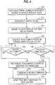
appropriate computer module 132. - There is described below with reference to Fig. 5A and 5B, an operation of the invention to reduce system overhead associated with resetting a delay timer which is used to determine whether a cessation of motion of the pointing device has occurred.
- Referring to Fig. 5A, the user first touches a pointing device down on the touch sensor in 150 and generates one point. In 152, after the first point is collected by the AUI, the pointing device that generated that point is identified; that is, the pointing device is identified as a finger, stylus, mouse, etc. In 154, the point generation rate is determined. Each pointing device generates points at different rates. The stylus, for example, generates 110 points per second, whereas the mouse generates 40 points per second. At 156, the system refers to a user profile and retrieves a delay timer value. There is a different delay timer value for each pointing device. For example, the stylus timer delay is 200 ms, whereas the finger timer delay is 300 ms. In 158, the delay timer value is divided by 2.3, an empirically derived constant, to yield 86 ms (i.e., 200 ms divided by 2.3
yields 86 ms). At 160, the number of points expected during this 86 ms period is then calculated. With a stylus generating 110 points per second, there would be approximately 9 input points during the 86 ms period. The system records the touch-down point and uses it as an anchor. The term "anchor" implies that the next point generated by the pointing device must be a predetermined distance from the touch-down point to be considered a movement of the pointing device. The predetermined distance may be varied in accordance with the system resolution. At 164, the point count is zeroed out. As the points are received, they are counted. In 166, the delay timer is started using the retrieved value. At this point, setup initialization is completed. - At 188, the user lifts the pointing device off the touch sensor. If the user lifts off, there will be no mouse emulation detected and the system categorizes the input points generated by the pointing device as a gesture or handwriting input and cancels the timer. In 192, the delay timer times out. The delay timer timed out because the user stopped moving the pointing device for time in excess of the delay period and the system stopped resetting the timer. When that happens, the system enters mouse emulation mode.
- In Fig. 5B, at 168, each new point generated is collected from the touch sensor. For the stylus, the points are received at 110 points per second. At 170, the point count is incremented. At 172, the X - Y coordinates of the newest input point are examined to see if the point is more than two picture elements (pels) from the anchor or the previous input point. If so, the system classifies the pointing device as having movement. In 174, the new point is recorded. The X-Y coordinates are used for the new anchor, and the timestamp of that point is saved. If there is no movement, the last two steps are omitted. At 178, the number of points received up to this time is calculated. If the number is an integer multiple of the divide rate, the system proceeds to 180 to see if motion had occurred within the last n points. ("n" in this case is 9.) The divide rate for the stylus would be 9, so the system would check for multiples of 9 (e.g., 9, 18, 27, etc.). If motion has occurred, the elapsed time is determined from the time the last motion point was received. If there has been any elapsed time since the last motion point, the elapsed time is subtracted from the original timer value, e.g., 200 ms. At 186, the timer delay is reset using the new timeout value which would be 200 ms minus the elapsed time between motion cessation and the nth point. In 178 and 180, if either of those tests resulted in no, the system exits.
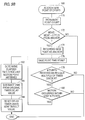
- In Fig. 6, there is shown a stroke consisting of a touch-down and a series of nine (9) points. As discussed previously, after 9 points are received from the stylus, the system checks to see if movement has occurred within the last 9 points. In the figure, the stylus movement has been relatively rapid. In actual use, the points are likely to be spaced more closely together.
- In Fig. 6, there has been motion within the last 9 points; the portion of the stroke from
point 8 topoint 9 has been inked. After the 9th point is received, the delay timer, which is waiting for a period of stability of 200 ms, is reset to zero and resumes waiting for the user to stop moving. - In Fig. 7, the user has continued to move on to
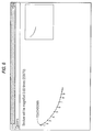
points point 18, the system, again, determines if any motion occurred in the previous 9 points. Again, the answer is yes. Motion occurred on the first 3 points (10-12). However, on the last 6 points there was no motion, so the 200 ms timer is reset. To account for the absence of motion for the last 6 points, probably 50 ms, the timer is reset at the value of 200 ms minus 50 ms which equals 150 ms. - Fig. 8 shows that the user never did again move the stylus. The stylus remained stationary after
point 12, and points 19-35 show there was no movement so the timer is never reset. At point 35, a timeout occurred because the user failed to move the pointing device for 200 ms. When the system detects a timeout, mouse emulation mode is entered to cause a mouse command input message to be produced. - The AUI system provides facilities for finger- and stylus-based user interface devices. When used with devices capable of tracking the movement of a user's finger or the movement of a stylus, AUI provides support for the handling of the resulting stroke information. These facilities include the visual tracing on the screen of ink flowing from the stylus, the delivery of the stroke information to application programs, and the delivery of the stroke information to recognition subsystems for further analysis.
- AUI employs a user interface technique where mouse emulation for the pointing device (stylus, finger or mouse) is delayed until the user stops moving the pointing device. Any stroke completed (i.e., pointing device is lifted off touch sensor) before movement has stopped is classified as a gesture or handwriting input. After motion stops, it is assumed the user intends to emulate a mouse input, and a mouse emulation mode begins. To effect the detection of motion cessation, the user must touch down and hold the pointing device stationary for a timeout period. "Stationary" is defined as no change in position greater than n pels, where 'n pels' can be expressed in either display or sensor resolution units. In one preferred embodiment, a value of two display pels is used. Examples of typical timeout values are 200 ms for a stylus, 300 ms for finger touch, and 200 ms for a mouse. These values represent a trade-off between minimizing the delay to enter mouse emulation and making gestures easy to stroke without inadvertently timing out during the stroke.
- The invention has particular application in a multi-tasking computer system. As described above, a single task or thread is typically dedicated to managing a delay timer used to determine motion cessation. In the prior art, for example, a stylus pointing device generates 110 points per second, one point every 9 ms.
- Thus, the prior art processor would need to switch to and from the timer thread every 9 ms when the stylus is in motion. As a result, 100% of the processing time of the system is taken up by managing the timer, assuming the processor takes 9 ms to process data for each point generated.
- In accordance with the present invention, this timer thread needs to be reset only every nth point generated by the pointing device used with the computer system. Thus, the system processor does not have to waste processing time to switch between a currently executing thread to the timer thread after each point is generated by a moving pointing device.
- To clarify the above description invention, the following pseudocode is provided to detail the logic flow:


While the invention has been particularly shown and described with reference to a preferred embodiment thereof, it will be understood by those skilled in the art that various changes in detail may be made therein without departing from the spirit, scope and teaching of the invention. For example, the above embodiment assumed a steady generation of points was made by the pointing device such that the timer used to determine cessation of a moving pointing device could be periodically reset after n points were generated. However, in a system where the movement of the pointing device is sporadic and a steady stream of points are not generated by a moving pointing device, the timer can be reset periodically at timed intervals, e.g., 86 ms, in accordance with the following alternative embodiment of the invention. - In this embodiment, an initial point generated by the pointing device is used as an anchor point (as in the embodiment described above). All subsequent points are then monitored as to their time period of generation (hereinafter referred to as a "timestamp") relative to the anchor point was generated. When a point is generated with a timestamp greater than a given interval of time, e.g., 86 ms, the timer is reset and the point is used as the new anchor point. According to this embodiment of the invention, the timer is periodically reset at given time intervals when points are generated within the predetermined time-delay period, e.g., 200 ms. If no points are generated by the pointing device, and no movement thereof is detected, then a timeout occurs and a the system enters a mouse emulation mode (as described above).
Claims (18)
- A method of reducing the processing time required to recognize the cessation of motion of a moving pointing device in an information processing system, the method comprising the steps of:
generating a series of points using a moving pointing device, said points being representative of positions of the pointing device;
periodically collecting a plurality of said points;
in response to determination that motion of the pointing device has occurred within said plurality of collected points, resetting a timer with a predetermined delay period; and
in response to measurement of the predetermined delay period by the timer, recognizing the cessation of motion of the pointing device. - The method as recited in Claim 1, which further comprises the steps of:
identifying the pointing device as one among several possible pointing devices; and
setting, in accordance with the identified pointing device, both the number of points within said plurality of points and also the predetermined delay period. - The method as recited in Claim 2, wherein the pointing device is a finger moving across a touch sensor, and further comprising the step of canceling the timer when the finger is lifted off the touch sensor.
- The method as recited in Claim 1, wherein the information processing system enters a mouse emulation mode in response to the recognition of motion cessation.
- The method as recited in claim 1, further comprising the steps of canceling the timer when the pointing device terminates its generation of points, and then entering a gesture recognition mode.
- A method for inputting position point data into a data processing system using a pointing device, said method comprising the steps of:
generating position points as the pointing device is moved about a touch sensor to control a display device;
detecting motion of said pointing device relative to said touch sensor within a predetermined number of previous position points; and
determining motion cessation of said pointing device in response to a timer measuring a predetermined delay period, wherein said timer is reset after every predetermined number of position points when motion of said pointing device has been detected. - The method recited in claim 6, further comprising the step of identifying a type of said pointing device, wherein said delay period is determined in accordance with the type identified.
- The method recited in claim 7, wherein, when motion of said pointing device has not been detected within a number of previous position points, said delay period is reduced in accordance with the number of previous position points.
- The method recited in claim 6, wherein the system accepts information from said pointing device as gesture or character information in response to movement and removal of said pointing device from said touch sensor prior to measurement of said delay period.
- The method as recited in claim 6, further comprising the steps of canceling the timer when the pointing device terminates its generation of points, and then entering a gesture recognition mode.
- A method of reducing processing time required in a multi-tasking computer system to input data, representative of position points, by using a first pointing device that emulates a second pointing device, the method comprising the steps of:
detecting when the first pointing device generates position points;
identifying a type of the first pointing device,
and setting a timer with a predetermined delay period corresponding to the identified type;
periodically collecting a plurality of position points generated by the first pointing device and storing the collected points in a stroke buffer, and detecting motion of the first pointing device;
resetting said timer after said plurality of points have been collected and motion has been detected, said timer being reset with a delay period that is reduced in accordance with a number of points that have been generated within a minimum distance from a preceding one of said plurality of points; and
in response to expiration of the delay period set in the timer, recognizing, at the last of said points stored in said stroke buffer, input data generated by the second pointing device. - A data processing system comprising:
a pointing device generating position points as it is moved about a touch sensor to control a display device;
a motion detector device detecting motion of said pointing device relative to said touch sensor within a predetermined number of previous position points; and
means, responsive to measuring of a predetermined delay period by a timer, for recognizing cessation of said pointing device, wherein said timer is reset after said predetermined number of position points when motion of said pointing device has been detected. - The data processing system recited in claim 12, wherein the system accepts information from said pointing device as mouse input data in response to a recognition of motion cessation.
- The data processing system recited in claim 12, wherein said touch sensor is a touch-sensitive display screen that displays information under control of said pointing device.
- The data processing system recited in claim 12, wherein the system is a multi-tasking computer system that dedicates a single task to managing said timer.
- The data processing system recited in claim 12, wherein the system enters a gesture recognition mode when the pointing device terminates its generation of points.
- A data processing system comprising:
a pointing device generating position points as it is moved about a touch sensor to control a display device;
a motion detector device detecting motion of said pointing device relative to said touch sensor within a predetermined time interval relative to a reference position point; and
means, responsive to measuring of a predetermined delay period by a timer, for recognizing cessation of said pointing device, wherein said timer is reset after said predetermined time interval when motion of said pointing device has been detected. - A method for inputting position point data into a data processing system using a pointing device, said method comprising the steps of:
generating position points as the pointing device is moved about a touch sensor to control a display device;
detecting motion of said pointing device relative to said touch sensor within a predetermined time interval; and
determining motion cessation of said pointing device in response to a timer measuring a predetermined delay period, wherein said timer is reset after every predetermined time interval when motion of said pointing device has been detected.
Applications Claiming Priority (2)
| Application Number | Priority Date | Filing Date | Title |
|---|---|---|---|
| US77448891A | 1991-10-10 | 1991-10-10 | |
| US774488 | 1996-12-30 |
Publications (2)
| Publication Number | Publication Date |
|---|---|
| EP0536554A1 true EP0536554A1 (en) | 1993-04-14 |
| EP0536554B1 EP0536554B1 (en) | 1998-05-20 |
Family
ID=25101405
Family Applications (1)
| Application Number | Title | Priority Date | Filing Date |
|---|---|---|---|
| EP92115547A Expired - Lifetime EP0536554B1 (en) | 1991-10-10 | 1992-09-11 | Method and apparatus for reducing system overhead for a touch screen device |
Country Status (8)
| Country | Link |
|---|---|
| US (1) | US5404458A (en) |
| EP (1) | EP0536554B1 (en) |
| JP (1) | JPH0736142B2 (en) |
| KR (1) | KR950012489B1 (en) |
| CN (1) | CN1026732C (en) |
| CA (1) | CA2076517A1 (en) |
| DE (1) | DE69225550T2 (en) |
| TW (1) | TW212236B (en) |
Cited By (6)
| Publication number | Priority date | Publication date | Assignee | Title |
|---|---|---|---|---|
| GB2301217A (en) * | 1995-05-26 | 1996-11-27 | Nokia Mobile Phones Ltd | Display driver |
| EP0690368A3 (en) * | 1994-06-29 | 1997-01-29 | Ibm | A pen-based computer system |
| WO2001008101A1 (en) * | 1999-07-27 | 2001-02-01 | Adl Systeme S.A. | Method and device for managing pixel transmission |
| WO2003065192A1 (en) * | 2002-01-31 | 2003-08-07 | Nokia Corporation | Method, system and device for distinguishing pointing means |
| EP2444885A1 (en) * | 2010-10-22 | 2012-04-25 | Aisin AW Co., Ltd. | Image display device, image display method, program, and computer readable medium |
| EP1408395A3 (en) * | 2002-09-26 | 2015-11-25 | Siemens Aktiengesellschaft | Method for automatic identification of user commands on a touch screen user interface |
Families Citing this family (138)
| Publication number | Priority date | Publication date | Assignee | Title |
|---|---|---|---|---|
| US8352400B2 (en) | 1991-12-23 | 2013-01-08 | Hoffberg Steven M | Adaptive pattern recognition based controller apparatus and method and human-factored interface therefore |
| CA2089784C (en) * | 1992-04-15 | 1996-12-24 | William Joseph Anderson | Apparatus and method for disambiguating an input stream generated by a stylus-based user interface |
| US5673066A (en) * | 1992-04-21 | 1997-09-30 | Alps Electric Co., Ltd. | Coordinate input device |
| US5764220A (en) * | 1992-09-11 | 1998-06-09 | Mitsubishi Denki Kabushiki Kaisha | Method of detecting contact of mouse with surface and mouse unit using this method |
| US5568604A (en) * | 1992-12-31 | 1996-10-22 | U S West Technologies, Inc. | Method and system for generating a working window in a computer system |
| DE69416960T2 (en) * | 1993-12-07 | 1999-08-19 | Seiko Epson Corp | Touch panel input device and method for generating input signals for an information processing device |
| US6262719B1 (en) | 1994-09-02 | 2001-07-17 | Packard Bell Nec, Inc. | Mouse emulation with a passive pen |
| US6092117A (en) * | 1994-09-02 | 2000-07-18 | Packard Bell Nec | System and method for automatically reconnecting a wireless interface device to a host computer |
| US6292181B1 (en) * | 1994-09-02 | 2001-09-18 | Nec Corporation | Structure and method for controlling a host computer using a remote hand-held interface device |
| US6209034B1 (en) | 1994-09-02 | 2001-03-27 | Nec Corporation | Remote keyboard macros activated by hot icons |
| US5867106A (en) * | 1994-09-02 | 1999-02-02 | Packard Bell Nec | Password switch to override remote control |
| US6137473A (en) * | 1994-09-02 | 2000-10-24 | Nec Corporation | System and method for switching control between a host computer and a remote interface device |
| US5974558A (en) * | 1994-09-02 | 1999-10-26 | Packard Bell Nec | Resume on pen contact |
| US5473745A (en) * | 1994-12-14 | 1995-12-05 | International Business Machines Corporation | Exposing and hiding a title bar behind its window using a visual cue |
| US5764218A (en) * | 1995-01-31 | 1998-06-09 | Apple Computer, Inc. | Method and apparatus for contacting a touch-sensitive cursor-controlling input device to generate button values |
| US5802388A (en) * | 1995-05-04 | 1998-09-01 | Ibm Corporation | System and method for correction and confirmation dialog for hand printed character input to a data processing system |
| US5761641A (en) * | 1995-07-31 | 1998-06-02 | Microsoft Corporation | Method and system for creating voice commands for inserting previously entered information |
| US5864815A (en) * | 1995-07-31 | 1999-01-26 | Microsoft Corporation | Method and system for displaying speech recognition status information in a visual notification area |
| US5748191A (en) * | 1995-07-31 | 1998-05-05 | Microsoft Corporation | Method and system for creating voice commands using an automatically maintained log interactions performed by a user |
| US5857172A (en) * | 1995-07-31 | 1999-01-05 | Microsoft Corporation | Activation control of a speech recognizer through use of a pointing device |
| US6126327A (en) * | 1995-10-16 | 2000-10-03 | Packard Bell Nec | Radio flash update |
| US5990875A (en) * | 1995-10-16 | 1999-11-23 | Packard Bell Nec | Double pen up event |
| US5996082A (en) * | 1995-10-16 | 1999-11-30 | Packard Bell Nec | System and method for delaying a wake-up signal |
| US6924790B1 (en) | 1995-10-16 | 2005-08-02 | Nec Corporation | Mode switching for pen-based computer systems |
| US6148344A (en) * | 1995-10-16 | 2000-11-14 | Nec Corporation | System and method for enabling an IPX driver to accommodate multiple LAN adapters |
| US6018806A (en) * | 1995-10-16 | 2000-01-25 | Packard Bell Nec | Method and system for rebooting a computer having corrupted memory using an external jumper |
| US6664982B1 (en) | 1995-10-16 | 2003-12-16 | Nec Corporation | Multi-user on-screen keyboard |
| US6005533A (en) * | 1995-10-16 | 1999-12-21 | Packard Bell Nec | Remote occlusion region |
| US6108727A (en) * | 1995-10-16 | 2000-08-22 | Packard Bell Nec | System having wireless interface device for storing compressed predetermined program files received from a remote host and communicating with the remote host via wireless link |
| US7512671B1 (en) * | 1995-10-16 | 2009-03-31 | Nec Corporation | Computer system for enabling a wireless interface device to selectively establish a communication link with a user selectable remote computer |
| US6279153B1 (en) | 1995-10-16 | 2001-08-21 | Nec Corporation | Multi-user flash ROM update |
| US5732283A (en) * | 1995-10-24 | 1998-03-24 | International Business Machines Corporation | System and method of providing universal support for multiple pointing devices |
| US5838819A (en) * | 1995-11-14 | 1998-11-17 | Lucent Technologies Inc. | System and method for processing and managing electronic copies of handwritten notes |
| US5893132A (en) | 1995-12-14 | 1999-04-06 | Motorola, Inc. | Method and system for encoding a book for reading using an electronic book |
| US5815407A (en) * | 1995-12-14 | 1998-09-29 | Motorola Inc. | Method and device for inhibiting the operation of an electronic device during take-off and landing of an aircraft |
| US5761681A (en) * | 1995-12-14 | 1998-06-02 | Motorola, Inc. | Method of substituting names in an electronic book |
| US5761682A (en) * | 1995-12-14 | 1998-06-02 | Motorola, Inc. | Electronic book and method of capturing and storing a quote therein |
| US5818426A (en) * | 1996-02-01 | 1998-10-06 | Aztech New Media Corporation | Peripheral-computer interfacing system and method |
| US6049329A (en) * | 1996-06-04 | 2000-04-11 | International Business Machines Corporartion | Method of and system for facilitating user input into a small GUI window using a stylus |
| US5862256A (en) * | 1996-06-14 | 1999-01-19 | International Business Machines Corporation | Distinguishing gestures from handwriting in a pen based computer by size discrimination |
| US5864635A (en) * | 1996-06-14 | 1999-01-26 | International Business Machines Corporation | Distinguishing gestures from handwriting in a pen based computer by stroke analysis |
| EP2343693A3 (en) * | 1996-08-12 | 2012-09-12 | Tyco Electronics Coroporation | Acoustic condition sensor employing a plurality of mutually non-orthogonal waves |
| KR19990015738A (en) | 1997-08-08 | 1999-03-05 | 윤종용 | Handheld Computer with Touchpad Input Control |
| US6610917B2 (en) | 1998-05-15 | 2003-08-26 | Lester F. Ludwig | Activity indication, external source, and processing loop provisions for driven vibrating-element environments |
| KR100401197B1 (en) * | 1998-11-20 | 2003-11-15 | 삼성전자주식회사 | Character recognition device with improved character recognition speed and method |
| US7966078B2 (en) | 1999-02-01 | 2011-06-21 | Steven Hoffberg | Network media appliance system and method |
| KR100810218B1 (en) * | 1999-03-18 | 2008-03-06 | 삼성전자주식회사 | Apparatus and method for processing touch screen panel data inputted through touch screen panel by user in digital mobile terminal |
| JP3998376B2 (en) * | 1999-09-10 | 2007-10-24 | 富士通株式会社 | Input processing method and input processing apparatus for implementing the same |
| US20030174125A1 (en) * | 1999-11-04 | 2003-09-18 | Ilhami Torunoglu | Multiple input modes in overlapping physical space |
| US20030132950A1 (en) * | 2001-11-27 | 2003-07-17 | Fahri Surucu | Detecting, classifying, and interpreting input events based on stimuli in multiple sensory domains |
| US6724373B1 (en) * | 2000-01-05 | 2004-04-20 | Brother International Corporation | Electronic whiteboard hot zones for controlling local and remote personal computer functions |
| JP3580208B2 (en) | 2000-02-04 | 2004-10-20 | ヤマハ株式会社 | String instrument |
| US6897853B2 (en) * | 2000-11-10 | 2005-05-24 | Microsoft Corp. | Highlevel active pen matrix |
| US6791536B2 (en) * | 2000-11-10 | 2004-09-14 | Microsoft Corporation | Simulating gestures of a pointing device using a stylus and providing feedback thereto |
| JP2002215146A (en) * | 2001-01-18 | 2002-07-31 | Kawai Musical Instr Mfg Co Ltd | Instruction inputting device of electronic musical instrument |
| US20030014674A1 (en) * | 2001-07-10 | 2003-01-16 | Huffman James R. | Method and electronic book for marking a page in a book |
| EP1481359B9 (en) * | 2002-02-06 | 2009-08-12 | Soundtouch Limited | Touch pad |
| WO2003071411A1 (en) * | 2002-02-15 | 2003-08-28 | Canesta, Inc. | Multiple input modes in overlapping physical space |
| US7499033B2 (en) * | 2002-06-07 | 2009-03-03 | Smart Technologies Ulc | System and method for injecting ink into an application |
| FR2841022B1 (en) * | 2002-06-12 | 2004-08-27 | Centre Nat Rech Scient | METHOD FOR LOCATING AN IMPACT ON A SURFACE AND DEVICE FOR IMPLEMENTING SAID METHOD |
| US20040001101A1 (en) * | 2002-06-27 | 2004-01-01 | Koninklijke Philips Electronics N.V. | Active window switcher |
| US11275405B2 (en) * | 2005-03-04 | 2022-03-15 | Apple Inc. | Multi-functional hand-held device |
| US7069357B2 (en) * | 2003-01-29 | 2006-06-27 | Numark Industries, Llc | Touch sensor system |
| JP4111897B2 (en) * | 2003-09-16 | 2008-07-02 | 日立ソフトウエアエンジニアリング株式会社 | Window control method |
| EP1695194A4 (en) * | 2003-12-19 | 2011-11-02 | Intel Corp | Creating responses for an electronic pen-computer multimedia interactive system |
| US8442331B2 (en) | 2004-02-15 | 2013-05-14 | Google Inc. | Capturing text from rendered documents using supplemental information |
| US7707039B2 (en) | 2004-02-15 | 2010-04-27 | Exbiblio B.V. | Automatic modification of web pages |
| US10635723B2 (en) | 2004-02-15 | 2020-04-28 | Google Llc | Search engines and systems with handheld document data capture devices |
| US7812860B2 (en) | 2004-04-01 | 2010-10-12 | Exbiblio B.V. | Handheld device for capturing text from both a document printed on paper and a document displayed on a dynamic display device |
| WO2008028674A2 (en) * | 2006-09-08 | 2008-03-13 | Exbiblio B.V. | Optical scanners, such as hand-held optical scanners |
| US7990556B2 (en) | 2004-12-03 | 2011-08-02 | Google Inc. | Association of a portable scanner with input/output and storage devices |
| US9143638B2 (en) | 2004-04-01 | 2015-09-22 | Google Inc. | Data capture from rendered documents using handheld device |
| US8146156B2 (en) | 2004-04-01 | 2012-03-27 | Google Inc. | Archive of text captures from rendered documents |
| US20060098900A1 (en) | 2004-09-27 | 2006-05-11 | King Martin T | Secure data gathering from rendered documents |
| US20060081714A1 (en) | 2004-08-23 | 2006-04-20 | King Martin T | Portable scanning device |
| US7894670B2 (en) | 2004-04-01 | 2011-02-22 | Exbiblio B.V. | Triggering actions in response to optically or acoustically capturing keywords from a rendered document |
| US9116890B2 (en) | 2004-04-01 | 2015-08-25 | Google Inc. | Triggering actions in response to optically or acoustically capturing keywords from a rendered document |
| US8620083B2 (en) | 2004-12-03 | 2013-12-31 | Google Inc. | Method and system for character recognition |
| US8874504B2 (en) | 2004-12-03 | 2014-10-28 | Google Inc. | Processing techniques for visual capture data from a rendered document |
| US8489624B2 (en) | 2004-05-17 | 2013-07-16 | Google, Inc. | Processing techniques for text capture from a rendered document |
| US7623119B2 (en) * | 2004-04-21 | 2009-11-24 | Nokia Corporation | Graphical functions by gestures |
| EP1640852A1 (en) * | 2004-06-25 | 2006-03-29 | Matsushita Electric Industrial Co., Ltd. | Command input device using touch panel display |
| US10201753B2 (en) * | 2004-07-16 | 2019-02-12 | Universal Entertainment Corporation | Gaming machine and program thereof |
| US8346620B2 (en) | 2004-07-19 | 2013-01-01 | Google Inc. | Automatic modification of web pages |
| JP4134008B2 (en) * | 2004-11-19 | 2008-08-13 | 任天堂株式会社 | Image processing apparatus and image processing program |
| US7692637B2 (en) * | 2005-04-26 | 2010-04-06 | Nokia Corporation | User input device for electronic device |
| JP2006314349A (en) * | 2005-05-10 | 2006-11-24 | Nintendo Co Ltd | Game program and game device |
| US8643605B2 (en) | 2005-11-21 | 2014-02-04 | Core Wireless Licensing S.A.R.L | Gesture based document editor |
| US8018440B2 (en) | 2005-12-30 | 2011-09-13 | Microsoft Corporation | Unintentional touch rejection |
| JP2008012199A (en) * | 2006-07-10 | 2008-01-24 | Aruze Corp | Game system and image display control method thereof |
| US7907117B2 (en) * | 2006-08-08 | 2011-03-15 | Microsoft Corporation | Virtual controller for visual displays |
| US7864163B2 (en) | 2006-09-06 | 2011-01-04 | Apple Inc. | Portable electronic device, method, and graphical user interface for displaying structured electronic documents |
| US8159457B2 (en) * | 2006-09-27 | 2012-04-17 | Yahoo! Inc. | Zero-click activation of an application |
| US20080154573A1 (en) * | 2006-10-02 | 2008-06-26 | Microsoft Corporation | Simulating new input devices using old input devices |
| CN101192124B (en) * | 2006-11-17 | 2010-04-21 | 中兴通讯股份有限公司 | System and method for automatic distinguishing and processing for touch screen input information |
| US7889184B2 (en) * | 2007-01-05 | 2011-02-15 | Apple Inc. | Method, system and graphical user interface for displaying hyperlink information |
| US7889185B2 (en) * | 2007-01-05 | 2011-02-15 | Apple Inc. | Method, system, and graphical user interface for activating hyperlinks |
| US8638363B2 (en) | 2009-02-18 | 2014-01-28 | Google Inc. | Automatically capturing information, such as capturing information using a document-aware device |
| US10126942B2 (en) * | 2007-09-19 | 2018-11-13 | Apple Inc. | Systems and methods for detecting a press on a touch-sensitive surface |
| US9110590B2 (en) | 2007-09-19 | 2015-08-18 | Typesoft Technologies, Inc. | Dynamically located onscreen keyboard |
| US9454270B2 (en) | 2008-09-19 | 2016-09-27 | Apple Inc. | Systems and methods for detecting a press on a touch-sensitive surface |
| US9489086B1 (en) | 2013-04-29 | 2016-11-08 | Apple Inc. | Finger hover detection for improved typing |
| US20120075193A1 (en) * | 2007-09-19 | 2012-03-29 | Cleankeys Inc. | Multiplexed numeric keypad and touchpad |
| US10203873B2 (en) | 2007-09-19 | 2019-02-12 | Apple Inc. | Systems and methods for adaptively presenting a keyboard on a touch-sensitive display |
| US8674946B2 (en) * | 2007-10-04 | 2014-03-18 | Alpine Electronics, Inc. | Method and apparatus for controlling timing of status change of electronics apparatus based on user's finger location and input speed |
| US20090167702A1 (en) * | 2008-01-02 | 2009-07-02 | Nokia Corporation | Pointing device detection |
| US20090284532A1 (en) * | 2008-05-16 | 2009-11-19 | Apple Inc. | Cursor motion blurring |
| KR20100009023A (en) * | 2008-07-17 | 2010-01-27 | (주)마이크로인피니티 | Apparatus and method for recognizing movement |
| US9069390B2 (en) | 2008-09-19 | 2015-06-30 | Typesoft Technologies, Inc. | Systems and methods for monitoring surface sanitation |
| US20100164756A1 (en) * | 2008-12-30 | 2010-07-01 | Nokia Corporation | Electronic device user input |
| US8447066B2 (en) | 2009-03-12 | 2013-05-21 | Google Inc. | Performing actions based on capturing information from rendered documents, such as documents under copyright |
| WO2010105246A2 (en) * | 2009-03-12 | 2010-09-16 | Exbiblio B.V. | Accessing resources based on capturing information from a rendered document |
| US20100238123A1 (en) * | 2009-03-17 | 2010-09-23 | Ozias Orin M | Input Device Gesture To Generate Full Screen Change |
| JP5427008B2 (en) * | 2009-11-27 | 2014-02-26 | 富士通テン株式会社 | In-vehicle display system |
| US9081799B2 (en) | 2009-12-04 | 2015-07-14 | Google Inc. | Using gestalt information to identify locations in printed information |
| US9323784B2 (en) | 2009-12-09 | 2016-04-26 | Google Inc. | Image search using text-based elements within the contents of images |
| US9268404B2 (en) * | 2010-01-08 | 2016-02-23 | Microsoft Technology Licensing, Llc | Application gesture interpretation |
| US9411504B2 (en) | 2010-01-28 | 2016-08-09 | Microsoft Technology Licensing, Llc | Copy and staple gestures |
| US8261213B2 (en) | 2010-01-28 | 2012-09-04 | Microsoft Corporation | Brush, carbon-copy, and fill gestures |
| US9519356B2 (en) | 2010-02-04 | 2016-12-13 | Microsoft Technology Licensing, Llc | Link gestures |
| US9965165B2 (en) | 2010-02-19 | 2018-05-08 | Microsoft Technology Licensing, Llc | Multi-finger gestures |
| US9310994B2 (en) * | 2010-02-19 | 2016-04-12 | Microsoft Technology Licensing, Llc | Use of bezel as an input mechanism |
| US9367205B2 (en) * | 2010-02-19 | 2016-06-14 | Microsoft Technolgoy Licensing, Llc | Radial menus with bezel gestures |
| US9454304B2 (en) | 2010-02-25 | 2016-09-27 | Microsoft Technology Licensing, Llc | Multi-screen dual tap gesture |
| CN102402192A (en) * | 2010-09-19 | 2012-04-04 | 钰宝科技股份有限公司 | Wireless screen display control device |
| DE102010048810A1 (en) | 2010-10-20 | 2012-04-26 | Hüttinger Elektronik Gmbh + Co. Kg | System for operating multiple plasma and / or induction heating processes |
| DE102010048809A1 (en) | 2010-10-20 | 2012-04-26 | Hüttinger Elektronik Gmbh + Co. Kg | Power supply system for a plasma application and / or an induction heating application |
| US10222974B2 (en) * | 2011-05-03 | 2019-03-05 | Nokia Technologies Oy | Method and apparatus for providing quick access to device functionality |
| US9104260B2 (en) | 2012-04-10 | 2015-08-11 | Typesoft Technologies, Inc. | Systems and methods for detecting a press on a touch-sensitive surface |
| US9582122B2 (en) | 2012-11-12 | 2017-02-28 | Microsoft Technology Licensing, Llc | Touch-sensitive bezel techniques |
| US20140168140A1 (en) * | 2012-12-18 | 2014-06-19 | Logitech Europe S.A. | Method and system for discriminating stylus and touch interactions |
| JP6271881B2 (en) * | 2013-06-26 | 2018-01-31 | キヤノン株式会社 | Information processing apparatus, control method therefor, program, and recording medium |
| KR20150008620A (en) * | 2013-07-15 | 2015-01-23 | 삼성전자주식회사 | Method and apparatus for providing electronic document |
| US10289302B1 (en) | 2013-09-09 | 2019-05-14 | Apple Inc. | Virtual keyboard animation |
| US9477337B2 (en) | 2014-03-14 | 2016-10-25 | Microsoft Technology Licensing, Llc | Conductive trace routing for display and bezel sensors |
| US10382012B2 (en) * | 2015-01-26 | 2019-08-13 | Pixart Imaging Inc. | Navigation device and track smoothing method thereof |
| US10606457B2 (en) | 2016-10-11 | 2020-03-31 | Google Llc | Shake event detection system |
| JP6832725B2 (en) * | 2017-01-31 | 2021-02-24 | シャープ株式会社 | Display device, display method and program |
Citations (4)
| Publication number | Priority date | Publication date | Assignee | Title |
|---|---|---|---|---|
| EP0271280A2 (en) * | 1986-12-11 | 1988-06-15 | AT&T Corp. | Arrangement for use in a computer |
| EP0289427A1 (en) * | 1987-04-29 | 1988-11-02 | Photonetics | Method and device to exploit a screen signal of a touch screen |
| EP0321356A1 (en) * | 1987-12-16 | 1989-06-21 | France Telecom | Multiple prediction method for estimating the movement of points in an electronic image |
| WO1989006032A1 (en) * | 1987-12-21 | 1989-06-29 | Ncr Corporation | Timing control for display system |
Family Cites Families (16)
| Publication number | Priority date | Publication date | Assignee | Title |
|---|---|---|---|---|
| US4334266A (en) * | 1980-04-21 | 1982-06-08 | Westinghouse Electric Corp. | Numerical control system with following error monitor |
| US4409836A (en) * | 1981-11-13 | 1983-10-18 | Motorola, Inc. | Apparatus and method for detecting the cessation of motion of a body |
| US4587630A (en) * | 1984-02-15 | 1986-05-06 | Hewlett-Packard Company | Intelligent programmable touchscreen system |
| JPS6280724A (en) * | 1985-10-04 | 1987-04-14 | Hitachi Ltd | Mouse control system |
| US4760386A (en) * | 1986-06-13 | 1988-07-26 | International Business Machines Corporation | Automatic hiding and revealing of a pointer during keyboard activity |
| US5025411A (en) * | 1986-12-08 | 1991-06-18 | Tektronix, Inc. | Method which provides debounced inputs from a touch screen panel by waiting until each x and y coordinates stop altering |
| JPS63172325A (en) * | 1987-01-10 | 1988-07-16 | Pioneer Electronic Corp | Touch panel controller |
| US4903012A (en) * | 1987-01-20 | 1990-02-20 | Alps Electric Co., Ltd. | Coordinate system input device providing registration calibration and a mouse function |
| US4886941A (en) * | 1987-05-19 | 1989-12-12 | Commodore Business Machines, Inc. | Circuit for interfacing mouse input device to computer system |
| JPS63311426A (en) * | 1987-06-15 | 1988-12-20 | Hitachi Ltd | Mouse control system |
| JP2532120B2 (en) * | 1988-02-17 | 1996-09-11 | キヤノン株式会社 | Coordinate input device |
| US5157384A (en) * | 1989-04-28 | 1992-10-20 | International Business Machines Corporation | Advanced user interface |
| US5027109A (en) * | 1989-06-08 | 1991-06-25 | Donovan Paul M | Apparatus and method for minimizing undesired cursor movement in a computer controlled display system |
| US5189403A (en) * | 1989-09-26 | 1993-02-23 | Home Row, Inc. | Integrated keyboard and pointing device system with automatic mode change |
| US5179368A (en) * | 1989-11-09 | 1993-01-12 | Lippincott Douglas E | Method and apparatus for interfacing computer light pens |
| US5187467A (en) * | 1991-01-10 | 1993-02-16 | Hewlett Packard Company | Universal light pen system |
-
1992
- 1992-08-14 JP JP21688792A patent/JPH0736142B2/en not_active Expired - Fee Related
- 1992-08-20 CA CA002076517A patent/CA2076517A1/en not_active Abandoned
- 1992-09-11 DE DE69225550T patent/DE69225550T2/en not_active Expired - Fee Related
- 1992-09-11 EP EP92115547A patent/EP0536554B1/en not_active Expired - Lifetime
- 1992-10-02 KR KR1019920018066A patent/KR950012489B1/en not_active IP Right Cessation
- 1992-10-04 CN CN92111114A patent/CN1026732C/en not_active Expired - Lifetime
- 1992-11-04 TW TW081108798A patent/TW212236B/zh active
-
1994
- 1994-02-24 US US08/201,147 patent/US5404458A/en not_active Expired - Lifetime
Patent Citations (4)
| Publication number | Priority date | Publication date | Assignee | Title |
|---|---|---|---|---|
| EP0271280A2 (en) * | 1986-12-11 | 1988-06-15 | AT&T Corp. | Arrangement for use in a computer |
| EP0289427A1 (en) * | 1987-04-29 | 1988-11-02 | Photonetics | Method and device to exploit a screen signal of a touch screen |
| EP0321356A1 (en) * | 1987-12-16 | 1989-06-21 | France Telecom | Multiple prediction method for estimating the movement of points in an electronic image |
| WO1989006032A1 (en) * | 1987-12-21 | 1989-06-29 | Ncr Corporation | Timing control for display system |
Cited By (11)
| Publication number | Priority date | Publication date | Assignee | Title |
|---|---|---|---|---|
| EP0690368A3 (en) * | 1994-06-29 | 1997-01-29 | Ibm | A pen-based computer system |
| GB2301217A (en) * | 1995-05-26 | 1996-11-27 | Nokia Mobile Phones Ltd | Display driver |
| GB2301217B (en) * | 1995-05-26 | 1999-12-15 | Nokia Mobile Phones Ltd | Display driver |
| WO2001008101A1 (en) * | 1999-07-27 | 2001-02-01 | Adl Systeme S.A. | Method and device for managing pixel transmission |
| FR2797077A1 (en) * | 1999-07-27 | 2001-02-02 | Adl Systeme Sa | METHOD AND DEVICE FOR MANAGING TRANSMISSION OF PIXELS |
| WO2003065192A1 (en) * | 2002-01-31 | 2003-08-07 | Nokia Corporation | Method, system and device for distinguishing pointing means |
| EP1408395A3 (en) * | 2002-09-26 | 2015-11-25 | Siemens Aktiengesellschaft | Method for automatic identification of user commands on a touch screen user interface |
| EP2444885A1 (en) * | 2010-10-22 | 2012-04-25 | Aisin AW Co., Ltd. | Image display device, image display method, program, and computer readable medium |
| CN102455875A (en) * | 2010-10-22 | 2012-05-16 | 爱信艾达株式会社 | Image display device, image display method, and program |
| US8520029B2 (en) | 2010-10-22 | 2013-08-27 | Aisin Aw Co., Ltd. | Image display device, image display method, and program |
| CN102455875B (en) * | 2010-10-22 | 2015-12-16 | 爱信艾达株式会社 | Image display device and method for displaying image |
Also Published As
| Publication number | Publication date |
|---|---|
| CN1026732C (en) | 1994-11-23 |
| CN1071524A (en) | 1993-04-28 |
| JPH05204533A (en) | 1993-08-13 |
| EP0536554B1 (en) | 1998-05-20 |
| US5404458A (en) | 1995-04-04 |
| CA2076517A1 (en) | 1993-04-11 |
| DE69225550T2 (en) | 1999-02-04 |
| DE69225550D1 (en) | 1998-06-25 |
| JPH0736142B2 (en) | 1995-04-19 |
| KR950012489B1 (en) | 1995-10-18 |
| TW212236B (en) | 1993-09-01 |
| KR930008595A (en) | 1993-05-21 |
Similar Documents
| Publication | Publication Date | Title |
|---|---|---|
| EP0536554B1 (en) | Method and apparatus for reducing system overhead for a touch screen device | |
| US5272470A (en) | Apparatus and method for reducing system overhead while inking strokes in a finger or stylus-based input device of a data processing system | |
| EP0690368A2 (en) | A pen-based computer system | |
| US8508489B2 (en) | System and method for injecting ink into an application | |
| KR920002755B1 (en) | Apparatus for mode changes method and apparatus for cursor control | |
| US7411575B2 (en) | Gesture recognition method and touch system incorporating the same | |
| EP0817000B1 (en) | Reshapable pointing device for touchscreens | |
| US5946406A (en) | Method and system for data entry of handwritten symbols | |
| CN1322406C (en) | Input processing method and input control apparatus | |
| US5872559A (en) | Breakaway and re-grow touchscreen pointing device | |
| US5870083A (en) | Breakaway touchscreen pointing device | |
| JP3850570B2 (en) | Touchpad and scroll control method using touchpad | |
| KR950014984B1 (en) | Method for buffering high band with data from an input device and data system | |
| US5614926A (en) | Word processor with a handwriting text processing function | |
| JP3407309B2 (en) | Coordinate input method and device | |
| JPS60209832A (en) | Indicating system of picture input point | |
| JPH05204535A (en) | Information processor | |
| JPH02110623A (en) | Position input system |
Legal Events
| Date | Code | Title | Description |
|---|---|---|---|
| PUAI | Public reference made under article 153(3) epc to a published international application that has entered the european phase |
Free format text: ORIGINAL CODE: 0009012 |
|
| AK | Designated contracting states |
Kind code of ref document: A1 Designated state(s): DE FR GB IT |
|
| 17P | Request for examination filed |
Effective date: 19930819 |
|
| 17Q | First examination report despatched |
Effective date: 19960320 |
|
| GRAG | Despatch of communication of intention to grant |
Free format text: ORIGINAL CODE: EPIDOS AGRA |
|
| GRAG | Despatch of communication of intention to grant |
Free format text: ORIGINAL CODE: EPIDOS AGRA |
|
| GRAH | Despatch of communication of intention to grant a patent |
Free format text: ORIGINAL CODE: EPIDOS IGRA |
|
| GRAH | Despatch of communication of intention to grant a patent |
Free format text: ORIGINAL CODE: EPIDOS IGRA |
|
| GRAA | (expected) grant |
Free format text: ORIGINAL CODE: 0009210 |
|
| AK | Designated contracting states |
Kind code of ref document: B1 Designated state(s): DE FR GB IT |
|
| PG25 | Lapsed in a contracting state [announced via postgrant information from national office to epo] |
Ref country code: IT Free format text: LAPSE BECAUSE OF FAILURE TO SUBMIT A TRANSLATION OF THE DESCRIPTION OR TO PAY THE FEE WITHIN THE PRESCRIBED TIME-LIMIT;WARNING: LAPSES OF ITALIAN PATENTS WITH EFFECTIVE DATE BEFORE 2007 MAY HAVE OCCURRED AT ANY TIME BEFORE 2007. THE CORRECT EFFECTIVE DATE MAY BE DIFFERENT FROM THE ONE RECORDED. Effective date: 19980520 |
|
| REF | Corresponds to: |
Ref document number: 69225550 Country of ref document: DE Date of ref document: 19980625 |
|
| ET | Fr: translation filed | ||
| PLBE | No opposition filed within time limit |
Free format text: ORIGINAL CODE: 0009261 |
|
| STAA | Information on the status of an ep patent application or granted ep patent |
Free format text: STATUS: NO OPPOSITION FILED WITHIN TIME LIMIT |
|
| 26N | No opposition filed | ||
| PGFP | Annual fee paid to national office [announced via postgrant information from national office to epo] |
Ref country code: FR Payment date: 19990917 Year of fee payment: 8 |
|
| PG25 | Lapsed in a contracting state [announced via postgrant information from national office to epo] |
Ref country code: FR Free format text: LAPSE BECAUSE OF NON-PAYMENT OF DUE FEES Effective date: 20010531 |
|
| REG | Reference to a national code |
Ref country code: FR Ref legal event code: ST |
|
| REG | Reference to a national code |
Ref country code: GB Ref legal event code: IF02 |
|
| PGFP | Annual fee paid to national office [announced via postgrant information from national office to epo] |
Ref country code: DE Payment date: 20060303 Year of fee payment: 14 |
|
| PG25 | Lapsed in a contracting state [announced via postgrant information from national office to epo] |
Ref country code: DE Free format text: LAPSE BECAUSE OF NON-PAYMENT OF DUE FEES Effective date: 20070403 |
|
| PGFP | Annual fee paid to national office [announced via postgrant information from national office to epo] |
Ref country code: GB Payment date: 20110919 Year of fee payment: 20 |
|
| REG | Reference to a national code |
Ref country code: GB Ref legal event code: PE20 Expiry date: 20120910 |
|
| PG25 | Lapsed in a contracting state [announced via postgrant information from national office to epo] |
Ref country code: GB Free format text: LAPSE BECAUSE OF EXPIRATION OF PROTECTION Effective date: 20120910 |