EP0549855A2 - System for controlling artificial knee joint action in an above knee prosthesis - Google Patents
System for controlling artificial knee joint action in an above knee prosthesis Download PDFInfo
- Publication number
- EP0549855A2 EP0549855A2 EP92115676A EP92115676A EP0549855A2 EP 0549855 A2 EP0549855 A2 EP 0549855A2 EP 92115676 A EP92115676 A EP 92115676A EP 92115676 A EP92115676 A EP 92115676A EP 0549855 A2 EP0549855 A2 EP 0549855A2
- Authority
- EP
- European Patent Office
- Prior art keywords
- knee
- piston
- knee joint
- flexion
- akp
- Prior art date
- Legal status (The legal status is an assumption and is not a legal conclusion. Google has not performed a legal analysis and makes no representation as to the accuracy of the status listed.)
- Granted
Links
Images


Classifications
-
- B—PERFORMING OPERATIONS; TRANSPORTING
- B62—LAND VEHICLES FOR TRAVELLING OTHERWISE THAN ON RAILS
- B62D—MOTOR VEHICLES; TRAILERS
- B62D57/00—Vehicles characterised by having other propulsion or other ground- engaging means than wheels or endless track, alone or in addition to wheels or endless track
-
- A—HUMAN NECESSITIES
- A61—MEDICAL OR VETERINARY SCIENCE; HYGIENE
- A61F—FILTERS IMPLANTABLE INTO BLOOD VESSELS; PROSTHESES; DEVICES PROVIDING PATENCY TO, OR PREVENTING COLLAPSING OF, TUBULAR STRUCTURES OF THE BODY, e.g. STENTS; ORTHOPAEDIC, NURSING OR CONTRACEPTIVE DEVICES; FOMENTATION; TREATMENT OR PROTECTION OF EYES OR EARS; BANDAGES, DRESSINGS OR ABSORBENT PADS; FIRST-AID KITS
- A61F2/00—Filters implantable into blood vessels; Prostheses, i.e. artificial substitutes or replacements for parts of the body; Appliances for connecting them with the body; Devices providing patency to, or preventing collapsing of, tubular structures of the body, e.g. stents
- A61F2/50—Prostheses not implantable in the body
- A61F2/60—Artificial legs or feet or parts thereof
- A61F2/64—Knee joints
-
- A—HUMAN NECESSITIES
- A61—MEDICAL OR VETERINARY SCIENCE; HYGIENE
- A61F—FILTERS IMPLANTABLE INTO BLOOD VESSELS; PROSTHESES; DEVICES PROVIDING PATENCY TO, OR PREVENTING COLLAPSING OF, TUBULAR STRUCTURES OF THE BODY, e.g. STENTS; ORTHOPAEDIC, NURSING OR CONTRACEPTIVE DEVICES; FOMENTATION; TREATMENT OR PROTECTION OF EYES OR EARS; BANDAGES, DRESSINGS OR ABSORBENT PADS; FIRST-AID KITS
- A61F2/00—Filters implantable into blood vessels; Prostheses, i.e. artificial substitutes or replacements for parts of the body; Appliances for connecting them with the body; Devices providing patency to, or preventing collapsing of, tubular structures of the body, e.g. stents
- A61F2/50—Prostheses not implantable in the body
- A61F2/68—Operating or control means
- A61F2/70—Operating or control means electrical
-
- A—HUMAN NECESSITIES
- A61—MEDICAL OR VETERINARY SCIENCE; HYGIENE
- A61F—FILTERS IMPLANTABLE INTO BLOOD VESSELS; PROSTHESES; DEVICES PROVIDING PATENCY TO, OR PREVENTING COLLAPSING OF, TUBULAR STRUCTURES OF THE BODY, e.g. STENTS; ORTHOPAEDIC, NURSING OR CONTRACEPTIVE DEVICES; FOMENTATION; TREATMENT OR PROTECTION OF EYES OR EARS; BANDAGES, DRESSINGS OR ABSORBENT PADS; FIRST-AID KITS
- A61F2/00—Filters implantable into blood vessels; Prostheses, i.e. artificial substitutes or replacements for parts of the body; Appliances for connecting them with the body; Devices providing patency to, or preventing collapsing of, tubular structures of the body, e.g. stents
- A61F2/50—Prostheses not implantable in the body
- A61F2/68—Operating or control means
- A61F2/74—Operating or control means fluid, i.e. hydraulic or pneumatic
- A61F2/748—Valve systems
-
- A—HUMAN NECESSITIES
- A61—MEDICAL OR VETERINARY SCIENCE; HYGIENE
- A61F—FILTERS IMPLANTABLE INTO BLOOD VESSELS; PROSTHESES; DEVICES PROVIDING PATENCY TO, OR PREVENTING COLLAPSING OF, TUBULAR STRUCTURES OF THE BODY, e.g. STENTS; ORTHOPAEDIC, NURSING OR CONTRACEPTIVE DEVICES; FOMENTATION; TREATMENT OR PROTECTION OF EYES OR EARS; BANDAGES, DRESSINGS OR ABSORBENT PADS; FIRST-AID KITS
- A61F2/00—Filters implantable into blood vessels; Prostheses, i.e. artificial substitutes or replacements for parts of the body; Appliances for connecting them with the body; Devices providing patency to, or preventing collapsing of, tubular structures of the body, e.g. stents
- A61F2/50—Prostheses not implantable in the body
- A61F2/68—Operating or control means
- A61F2/74—Operating or control means fluid, i.e. hydraulic or pneumatic
-
- A—HUMAN NECESSITIES
- A61—MEDICAL OR VETERINARY SCIENCE; HYGIENE
- A61F—FILTERS IMPLANTABLE INTO BLOOD VESSELS; PROSTHESES; DEVICES PROVIDING PATENCY TO, OR PREVENTING COLLAPSING OF, TUBULAR STRUCTURES OF THE BODY, e.g. STENTS; ORTHOPAEDIC, NURSING OR CONTRACEPTIVE DEVICES; FOMENTATION; TREATMENT OR PROTECTION OF EYES OR EARS; BANDAGES, DRESSINGS OR ABSORBENT PADS; FIRST-AID KITS
- A61F2/00—Filters implantable into blood vessels; Prostheses, i.e. artificial substitutes or replacements for parts of the body; Appliances for connecting them with the body; Devices providing patency to, or preventing collapsing of, tubular structures of the body, e.g. stents
- A61F2/50—Prostheses not implantable in the body
- A61F2002/5003—Prostheses not implantable in the body having damping means, e.g. shock absorbers
-
- A—HUMAN NECESSITIES
- A61—MEDICAL OR VETERINARY SCIENCE; HYGIENE
- A61F—FILTERS IMPLANTABLE INTO BLOOD VESSELS; PROSTHESES; DEVICES PROVIDING PATENCY TO, OR PREVENTING COLLAPSING OF, TUBULAR STRUCTURES OF THE BODY, e.g. STENTS; ORTHOPAEDIC, NURSING OR CONTRACEPTIVE DEVICES; FOMENTATION; TREATMENT OR PROTECTION OF EYES OR EARS; BANDAGES, DRESSINGS OR ABSORBENT PADS; FIRST-AID KITS
- A61F2/00—Filters implantable into blood vessels; Prostheses, i.e. artificial substitutes or replacements for parts of the body; Appliances for connecting them with the body; Devices providing patency to, or preventing collapsing of, tubular structures of the body, e.g. stents
- A61F2/50—Prostheses not implantable in the body
- A61F2/68—Operating or control means
- A61F2/70—Operating or control means electrical
- A61F2002/704—Operating or control means electrical computer-controlled, e.g. robotic control
-
- A—HUMAN NECESSITIES
- A61—MEDICAL OR VETERINARY SCIENCE; HYGIENE
- A61F—FILTERS IMPLANTABLE INTO BLOOD VESSELS; PROSTHESES; DEVICES PROVIDING PATENCY TO, OR PREVENTING COLLAPSING OF, TUBULAR STRUCTURES OF THE BODY, e.g. STENTS; ORTHOPAEDIC, NURSING OR CONTRACEPTIVE DEVICES; FOMENTATION; TREATMENT OR PROTECTION OF EYES OR EARS; BANDAGES, DRESSINGS OR ABSORBENT PADS; FIRST-AID KITS
- A61F2/00—Filters implantable into blood vessels; Prostheses, i.e. artificial substitutes or replacements for parts of the body; Appliances for connecting them with the body; Devices providing patency to, or preventing collapsing of, tubular structures of the body, e.g. stents
- A61F2/50—Prostheses not implantable in the body
- A61F2/76—Means for assembling, fitting or testing prostheses, e.g. for measuring or balancing, e.g. alignment means
- A61F2002/7615—Measuring means
- A61F2002/7635—Measuring means for measuring force, pressure or mechanical tension
Definitions
- a knee joint is looked at as a simple hinge, there are two separate actions which can occur. In “flexion”, the knee joint rotates to enable the upper and lower leg segments to move closer together. In “extension” the knee joint rotates in the opposite direction, the leg segments move apart and the leg straightens.
- control or stiffness be applicable separately and variably in each of the flexion and extension modes. For example, it is desirable at the beginning of the stance (i.e. weight bearing) phase of the step to allow a small amount of knee flexion to occur and to then lock the knee against further downward flexion while simultaneously freeing the knee to extend as the leg straightens due to body action. So in the latter phase of this action, the knee joint is altered to being locked or stiff in flexion and free in extension, at the same time.
- An upper spring retainer 17 is mounted on the base of the servo motor bracket 14, for a purpose to be described.
Landscapes
- Health & Medical Sciences (AREA)
- Engineering & Computer Science (AREA)
- Transplantation (AREA)
- Vascular Medicine (AREA)
- Animal Behavior & Ethology (AREA)
- Cardiology (AREA)
- Biomedical Technology (AREA)
- Heart & Thoracic Surgery (AREA)
- Veterinary Medicine (AREA)
- Life Sciences & Earth Sciences (AREA)
- Oral & Maxillofacial Surgery (AREA)
- General Health & Medical Sciences (AREA)
- Public Health (AREA)
- Orthopedic Medicine & Surgery (AREA)
- Chemical & Material Sciences (AREA)
- Combustion & Propulsion (AREA)
- Transportation (AREA)
- Mechanical Engineering (AREA)
- Prostheses (AREA)
Abstract
Description
- This invention provides a system for controlling the rotation of a knee joint of an above knee prosthesis. The system employs a microprocessor, responsive to lower leg strain and knee angle measurements originating from sensors on the prosthesis, to control a hydraulic damper through operation of a valve assembly associated with the damper, to thereby passively damp or resist the rotation of the artificial knee joint.
- As previously stated, the present invention is used with an artificial leg or prosthesis worn by an above knee amputee.
- There are today about 50 different above knee prosthetic devices on the market. Many of these prostheses involve:
- a socket for receiving and engaging the stump of the user;
- a knee bracket rigidly connected to the socket;
- a frame extending down from the bracket and being pivotally connected to the bracket by a horizontal shaft, said bracket, shaft and frame together combining to form an artificial knee joint;
- a pylon and artificial foot connected to the base of the frame; and
- means for controlling the knee joint by locking it to prevent it from buckling under load in the stance phase of a step, and freeing it in the swing phase of the step.
- Now, the biological or natural knee joint is powered by the actions of muscles. Muscle has two elements. One is the active force developed by contraction and the other is variable stiffness. It has not been feasible to duplicate muscle contraction in leg prosthetics, due to limitations arising from weight and bulk. As a result, research has focused on implementing stiffness into the knee joint. This has usually involved switching the knee joint between one of two modes: locked up or free to rotate.
- In recent years, researchers have sought improvement in controlling the action of the artificial knee joint, as a way to improve gait and enable the amputee to better deal with certain distinct actions, such as descending stairs or lowering into a sitting position.
- A relevant patent in this regard is French patent 2623-086-A. This patent teaches providing a strain gage sensor on the frame between the knee joint and foot, to measure load. The electronic signals from the sensor are transmitted to a microprocessor which monitors the load measurement. When the load signal indicates that the swing phase of the step is ending and load is being applied to the leg, the microprocessor causes a motor or electromagnet to lock up the knee joint. When the stance phase is complete, the microprocessor instructs the actuator to release the knee joint, so that it is free to pivot in the swing phase.
- Another relevant prior art reference is Russian patent SU1333-333-A. This patent teaches using a sensor at the knee hinge, to measure knee angle. Means lock or free the knee hinge in response to the knee angle measurements.
- Another relevant prior art device is known as the Henschke Mauch S-N-S system for controlling an above knee prosthesis. This system incorporates a linear hydraulic damper for resisting rotation of the knee joint at a single damping rate in the stance phase. The damping rate can be varied by manual adjustment. When the knee joint is fully extended, the damper assumes a non-resisting mode. Otherwise stated, the system lacks automatic variation of damping and incorporates only two states, namely high resistance to flexion in stance phase and free rotation in swing phase.
- If a knee joint is looked at as a simple hinge, there are two separate actions which can occur. In "flexion", the knee joint rotates to enable the upper and lower leg segments to move closer together. In "extension" the knee joint rotates in the opposite direction, the leg segments move apart and the leg straightens. For an artificial knee joint to more closely simulate a biological knee joint, it is necessary that control or stiffness be applicable separately and variably in each of the flexion and extension modes. For example, it is desirable at the beginning of the stance (i.e. weight bearing) phase of the step to allow a small amount of knee flexion to occur and to then lock the knee against further downward flexion while simultaneously freeing the knee to extend as the leg straightens due to body action. So in the latter phase of this action, the knee joint is altered to being locked or stiff in flexion and free in extension, at the same time.
- To applicant's knowledge, there is no artificial knee joint mechanism disclosed in the prior art which enables separate, simultaneous and automatic variable control of flexion and extension.
- If such a mechanism could be devised, then a much more sophisticated control over the knee joint action could be implemented.
- It is the object of the present invention to supply such a mechanism and to then incorporate it in an improved overall prosthesis.
- The present invention relates to an on-board, computer-directed system adapted to provide improved automatic control of knee joint rotation in an above knee prosthesis (AKP) having upper and lower leg segments joined by the knee joint, said lower leg segment having a foot. In general, the system comprises:
- a linear, hydraulic damper which can separately and variably damping or resisting each of flexion and extension rotational movements of the knee joint;
- electronic sensing means for measuring each of AKP knee angle and lower leg strain (which are respectively indicative of the angle between the leg segments and the position of the center of gravity of the user's body relative to the AKP foot) and emitting signals indicative thereof;
- actuating means, such as a servo motor, for adjusting the damping means to vary the resistance to rotation of the knee joint in at least one of flexion and extension; and
- programmed computer means for receiving the emitted signals from the sensing means continuously establishing from said signals the state of the AKP in the course of a repetitive movement and activating the actuating means as required to vary damping to substantially simulate knee action. More particularly, the computer means is preferably adapted to do this by comparing the signals to stared threshold values which are indicative of pre-determined transition point between states of the AKP in the course of a movement, and, when the received signal values correlate with stored values, then causing the actuating means to vary damper resistance as required so that the AKP knee joint action substantially simulates natural knee action.
- It will be noted that the invention involves separate variation of damping of AKP knee joint action in each of flexion and extension. "Damping" for this specification means resisting rotational movement of the knee joint. The resistance may be substantially complete, in which case the knee joint is substantially prevented from rotating in one or both of flexion and extension. The resistance may be partial, in which case the rate of rotation of the knee joint is restricted in one or both of flexion and extension. Or the resistance may be non-existent, in which case the knee joint is free to rotate in one or both of flexion and extension. Alternatively stated, the damper is adapted to control the rate of rotation of the knee joint in one or both of flexion and extension.
- To enable such bi-directional damping, applicant has developed a novel damper incorporating a piston and means for controlling the piston. More particularly, the variable, linear, hydraulic damper comprises:
- a hollow closed cylinder filled with hydraulic fluid and having a cylindrical hollow piston adapted to slide longitudinally within the cylinder chamber;
- the piston preferably has axial rods extending from its ends, which rods project through sealed openings in the end walls of the cylinder. The piston further carries an exterior circumferential seal ring between its ends, for sealing against the side wall of the cylinder;
- a first aperture and check valve assembly, associated with a first end wall of the piston, enables fluid to enter the piston chamber from the first end of the cylinder chamber;
- a second aperture and check valve assembly, associated with the second end wall of the piston, allows fluid to enter the piston chamber from the second end of the cylinder chamber;
- a first pair of diametrically opposed ports extend through the piston side wall adjacent its first end, on one side of the seal ring;
- a second pair of diametrically opposed ports extend through the piston side wall adjacent its second end, on the other side of the seal ring;
- preferably, each first port is offset circumferentially from the second port on that side of the piston;
- preferably, each port is slit-like in configuration;
- a valve preferably extends into the cylinder and piston chambers and is adapted to progressively reduce or increase the effective area of the first (or flexion) ports available for fluid flow and separately progressively reduce or increase the area of the second (or extension) ports;
- most preferably the valve comprises a rotatable shaft extending into the piston chamber in parallel relation to the cylinder axis, said shaft carrying a pair of radially protruding, diametrically opposed lobes, each lobe being adapted to substantially seal against the inside surface of the piston side wall, each lobe further being adapted, when the shaft is rotated, to progressively cover or uncover the adjacent flexion and extension ports, to thereby separately and simultaneously control flow area through the flexion and extension ports.
- In use, one rod of the piston is connected to one segment of the AKP and the far end of the cylinder is connected to the other segment. For purposes of this description, it is assumed that the upper push rod of the damper piston is pivotally connected to the upper leg segment of the AKP and the lower end of the cylinder is pivotally connected to the lower leg segment. Therefore, in flexion the damper will contract and thus the piston will be driven downwardly in the cylinder by body load. In extension, the damper lengthens and the piston is pulled upwardly by body action.
- In the operation of the damper:
- If the valve is positioned to enable flexion and if the piston is forced downwardly, thereby pressurizing fluid in the lower end of the cylinder chamber, fluid will flow upwardly through the lower check valve and extension ports, if open, into the piston chamber and will leave the piston chamber through the upper flexion ports - fluid will not leave the piston chamber through the extension ports (if uncovered) because there is no significant fluid pressure differential between the lower end of the cylinder chamber and the piston chamber;
- If the valve is positioned to enable extension and if the piston is pulled upwardly, thereby pressurizing fluid in the upper end of the cylinder chamber, fluid will flow downwardly through the upper check valve and flexion ports, if open, into the piston chamber and will leave the piston chamber through the lower extension ports - again fluid will not leave the piston chamber through the flexion ports because there is no significant fluid pressure differential between the upper end of the cylinder chamber and the piston chamber.
- It will be noted that the damper design is characterized by the following attributes:
- The valve can be adjusted to vary port areas and thus fluid flow rates to thereby vary resistance to knee joint rotation in either flexion or extension at the same time, thereby enabling variation of damping in both directions at the same time;
- Because the ports are provided in diametrically opposed pairs, the valve does not get pressed against one side of the piston wall under heavy load and therefore does not seize up or become difficult to move - thus a small motor and shaft can be used to control the damper, which contributes to the compactness and lightness of the unit;
- Because the damper is hydraulic, it is not significantly affected by wear and remains substantially consistent in its damping performance, thereby enabling the user to become accustomed to its "action" and to gain confidence in its performance. One could argue that the temperature of the hydraulic oil could vary and this would affect consistency of performance but this effect is minimized by using aircraft hydraulic fluid.
- In a broad aspect, the damper design therefore involves providing:
- a pair of closed chambers (for example the two ends of the cylinder chamber;
- means (for example the piston and cylinder) connected to the leg segments and forming two passageways (for example each formed by a check valve assembly, the piston chamber and a pair of the ports), for moving or pumping fluid from one end chamber to the other through one of the passageways when the leg segments are moving together and through the other of the passageways when the leg segments are moving apart; and
- means (for example the valve and port assembly) for regulating the flow of fluid through each passageway.
- In another aspect of the invention, advantage is taken of the repetitive nature of leg actions. If, for example, one is walking along a level surface, there are patterns of knee angle and lower leg strain measurements which do not change significantly from step to step. By monitoring the two sets of signals and timing, the computer software can determine the stage or state of AKP motion and can initiate appropriate changes in flexion and extension capability. If there is deviation from the regular pattern, such as stubbing the AKP toe in the course of swing phase, the software can detect this change and initiate corrective action.
- Thus the system incorporates a method for controlling the knee joint of an AKP, which can be stated in the case of level walking as follows:
- storing, in a computer memory, threshold values of lower leg strain and knee angle, which values are indicative of the knee bending in stance phase, of anterior positioning of the center of gravity of body weight relative to the ankle or foot, and of swing phase, all in the course of a step along a level surface;
- continuously sensing lower leg strain and knee angle during use of the AKP and producing electronic signals corresponding thereto;
- comparing the signals against the stored threshold values and, when the signals substantially correlate with threshold values, actuating means for altering the rate of rotation of the knee joint in at least one of flexion and extension to enable the knee joint to flex at about the beginning of stance phase, to lock the knee joint against flexion while enabling extension in the middle portion of stance phase, and to free the knee joint as it approaches the swing phase, thereby substantially simulating natural knee action; and
- repeating the foregoing repetitiously.
- By combining the sensing means, the damper having means which can simultaneously and separately control flexion and extension and the software based on the profiles of repetitive motion, a knee joint system has been evolved which is characterized by closely controlled, predictable responses. This results in the user gaining confidence in the system which then manifests itself in the form of a longer and more rhythmic gait. The software can react similarly whether the gait is fast or slow. And the software can be "fine tuned" to the particular user to gain further compatibility or altered to modify the operation of the AKP. In addition, the system is adaptable to controlling the knee joint in the course of actions other than level walking, such as stair descent and sitting.
- From the foregoing, it will be understood that the invention utilizes programmed computer means for receiving the emitted signals from the sensing means, continuously establishing from said signals the state of the AKP in the course of a movement and activating the actuating means to vary damping to substantially simulate natural knee action. More particularly, the programmed computer means is adapted to compare the emitted signals against stored threshold values indicative of transition points between states of a repetitive movement of the AKP and, when the signals substantially correlate with threshold values, to alter the rate of rotation of the knee joint in one or both of flex-on and extension. Preferably, the stored threshold values are selected from the group consisting of the absolute and derivative values of knee angle and the position of the center of gravity of the user's body relative to the AKP foot, the duration from the last transition point and the possible future states in the course of the movement.
- The invention described can be thought of as a machine which reacts to the amputee's movements, thus improving gait. Confidence in the machine is necessary for the amputee to take full advantage of the machine's capabilities. This confidence is developed by ensuring that the machine reactions are reproducible, step after step.
- In order to obtain consistent and reproducible reactions, the invention takes advantage of the reproducible mechanics of the prosthesis during normal walking. As previously stated, during each step the knee goes through a pattern of movement which is basically the same, step after step. Also reproducible from step to step are the strains on the frame of the AKP, developed by the weight of the amputee, and the angle changes of the knee joint.
- The repetitive nature of the signals is an important aspect of the success of the invention. This allows the prosthesis to have consistent man/machine interactions. The prosthesis is a tool used by the amputee to perform different tasks. If the performance of this tool is predictable and reproducible, then user confidence is gained.
- With the reactions occurring at the same time and in the same manner for each step, the amputee develops trust in the machine and is able to walk with a continuous fluid motion.
- In summary, the invention works on the principle that each step can be divided into segments or states and that a machine reaction can be developed for each segment, thus improving gait. The division of the step is carried out by first obtaining information from the prosthesis, conditioning this information with electronics and analyzing it with software, and then implementing machine reaction by separately and simultaneously varying resistance to flexion and extension rotation of the knee joint.
-
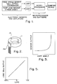
- Figure 1 is a block diagram showing the flow of information in the system;
- Figure 2 is a perspective simplified view of the Hall effect sensor used for providing signals indicative of knee angle;
- Figure 3 is a plot of knee angle sensor output versus knee joint rotation;
- Figure 4 is a perspective view of the prosthesis in exploded form;
- Figure 4A is a perspective view of the prosthesis in assembled form;
- Figure 5 is a plot of strain sensor output versus strain or load on the prosthesis;
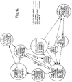
- Figure 6 is a diagram showing the states in level walking, with the appropriate state conditions shown;
- Figure 6a is a diagram showing the states in level walking and correlating them with leg action, piston position and valve position;
- Figure 7 is a plot showing the relationship between knee angle and strain (ankle bending moment or load) signals, related to the states, for level walking;
- Figure 7a is a diagram showing the states in stair descent and correlating them with leg action, piston position and valve position;
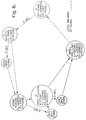
- Figure 8 is a diagram showing the states in sitting down, with the appropriate state conditions shown;
- Figure 8a is a diagram showing the states in sitting down and correlating them with leg action, piston position and valve position;
- Figure 9 is a plot showing the relationship between knee angle and strain signals, related to the states, for sitting down;
- Figure 10 is a diagram showing the states in stair descent, with the appropriate state conditions shown;
- Figure 11 is a plot showing the relationship between knee angle and strain signals, related to the states, for stair descent;
- Figure 12 is a comprehensive diagram showing the states and conditions for the various modes of action;
- Figure 12a is a comprehensive diagram corresponding with Figure 12 and showing the various body actions;
- Figures 13 and 14 are simplified sectional side views showing the piston and cylinder in flexion and extension modes;
- Figure 15 is a simplified end view of the internals of the piston;
- Figures 16 - 24 are views similar to Figure 15, showing the valve in various positions;
- Figure 25 is a side sectional view of the cylinder and piston;
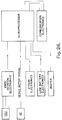
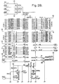
- Figure 26 is an overall circuit diagram of the system;
- Figure 27 is a diagram of the communication circuit;
- Figure 28 is a diagram of the microprocessor chip;
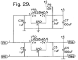
- Figure 29 is a diagram of the voltage references and regulator for the analog to digital convertor located on the microprocessor chip;
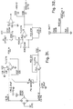
- Figure 30 is a diagram of the conditioning electronics for the Hall effect sensor;
- Figure 31 is a diagram of the conditioning electronics for the strain sensor;
- Figure 32 is a diagram of the conditioning electronics for low battery detection;
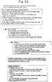
- Figure 33 is a flow chart of the software and Figure 34 is an interrupt service routine which is activated every 20 milliseconds; and
- Figure 35 is a perspective view showing strain gauge positioning on the base of the frame.
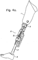
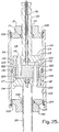
- Having reference to Figures 4a and 4b, the prosthesis A comprises a
suction socket 1 which is custom fabricated to closely fit the stump of the amputee and to cling to it by suction. An adjustingplate 2 is attached to the base of thesocket 1. Aknee bracket 3 is secured by screws to the adjustingplate 2. Theknee bracket 3 has apertured shaft supports 3a, 3b for receiving, supporting and affixing the main kneejoint shaft 9 and thedamper shaft 15 respectively. Aframe 4, having abearing 4a at its upper end, is rotatively mounted to theknee bracket 3 by themain shaft 9, which extends through thebearing 4a. Theframe 4 is therefore free to rotate or pivot on the fixedmain shaft 9. At its lower end, theframe 4 forms arectangular socket member 4b for receiving arectangular block 7a which is clamped to the upper end of thefoot pylon 7. Screws secure thepylon block 7a to theframe socket member 4b. Afoot 8 is secured to the lower end of thepylon 7. - An upper bearing
housing 12 is mounted for rotation on thedamper shaft 15. Thedamper shaft 15 is located to the rear of the main kneejoint shaft 9, so that theshaft 15 and upper bearinghousing 12 follow an arc relative to theshaft 9 when theknee bracket 3 rotates or pivots. - A
Hall effect sensor 13, shown in Figure 2, is provided to monitor the change in knee angle or knee joint rotation. Thesensor 13 used is available from Sprague Electronics and is designated as model UGN-3503U. Thissensor 13 comprises aring magnet 11, which is fixed to thestationary damper shaft 15 of theknee bracket 3 by aring magnet keeper 10. Thesensor 13 further comprises aHall effect transducer 13a, which is located in the rotatable upper bearinghousing 12 and which is positioned facing thering magnet 11. As knee joint rotation occurs, the bearinghousing 12 moves around thedamper shaft 15, causing thetransducer 13a to move relative to thering magnet 11. - The
transducer 13a has a voltage output which is dependent on the magnet flux intensity (north or south pole) directly before it. Therefore, as the knee joint rotates, the output oftransducer 13a changes. The signal from the linear Hall effect transducer is amplified to produce .5 volt with a knee joint extended fully and 4.5 volts with the knee joint flexed fully. Included in the circuit is a gain adjustment and an offset control. Stated otherwise, the signal of thetransducer 13a is lowest when the knee is straight and increases as the knee is bent. Figure 3 shows a typical sensor voltage output with respect to knee angle after amplification. - The forces on the
foot 8 are established by measuring the strain of theframe 4. This is done usingfoil strain gauges 6 available from Micro Measurements Group Inc., Raleigh, North Carolina under designation CEA - 06 - 062 UW-350. Fourgauges 6 are used, two at the front and two at the rear of theframe 4, located between theframe apertures 101 and the base of theframe 4, to measure and differentiate between load on the heel and load on the toe of thefoot 8. Stated otherwise, the strain measurement provides an indication as to whether the user body center of gravity is in the anterior, centred or posterior position relative to the AKP foot. The four gauges are wired in a wheatstone bridge configuration to produce an electric signal which changes proportionally with strain. The wheatstone bridge configuration is a standard arrangement for determining the resistance change of strain gauges. The output of the bridge is amplified by a differential instrumentation amplifier 126 to produce an output signal of .5 volts when the heel is loaded fully and 4.5 volts when the toe is loaded fully. No load or similar load on the toe and heel produces 2.5 volts. Included in the circuit is gain adjustment and an offset adjustment. Figure 6 shows a typical voltage output of the bridge with respect to foot loading after the signal is amplified. It will be noted that the load signal decreases as the heel is loaded and increases as the toe is loaded. - A
servo motor bracket 14 is secured to the base of the bearinghousing 12. Aservo motor 16 is mounted within thebracket 14. The motor used is available from Airtronics Ltd. under designation 94737. - An
upper spring retainer 17 is mounted on the base of theservo motor bracket 14, for a purpose to be described. - A damper B is positioned between the
servo motor bracket 14 and the base of theframe 4. - The damper B comprises a
hollow cylinder 26, which is externally threaded. A lowerspring mount ring 27 is threaded onto the outside surface of thecylinder 26, for a purpose explained below. A lowerbearing mount ring 29 is also adjustably threaded onto the outside surface of thecylinder 26, at its lower end. Thering 29 has radially extending threadedbores 100, normal to its central axis, which fitlower bearing pins 5 which are threaded throughapertures 101 in the base of theframe 4. Thus the base of thecylinder 26 is pivotally coupled to the base of theframe 4 by threading thepins 5 into thebores 100 of thering 29. Alock ring 28, threaded onto the external surface of thecylinder 26, is tightened against thering 29 to lock it in place. - A
lower cap 30 fits into thebore 102 of thecylinder 26 at its lower end and closes the bore. Thelower cap 30 is held in place by asnap ring 103. Thelower cap 30 carries a circumferential O-ring 104, for sealing against theside wall 105 of thecylinder 26. Anaperture 106 is formed through thecap 30. An O-ring 107 is mounted in thisaperture 106, sealing around thedummy push rod 25 of apiston 24. - At its upper end, the
cylinder 26 has anupper cap 21 which fits into the cylinder bore 102 and is held in place by asnap ring 108. Theupper cap 21 also carries a circumferential O-ring 109, for sealing against theside wall 105 of thecylinder 26. An aperture 110 is formed through thecap 21. An O-ring 111 is mounted in this aperture 110, for sealing around thepush rod 22 of thepiston 24. - The hollow
cylindrical piston 24 is positioned in thecylinder bore 102. Thepiston 24 comprises an open-endeddrum 112 having upper andlower end caps push rod 22 extends upwardly from theupper end cap 113, through the sealed aperture 110 in thecylinder cap 21, and is secured to theservo motor housing 14. From the foregoing, it will be noted that the bearinghousing 12,servo motor housing 14 and pushrod 22 form a train of components connected to thedamper shaft 15 andbracket plate 3. Thus as thesocket 1 pivots about themain shaft 9, this rotational movement is converted into linear movement of thepush rod 22 andpiston 24. - A
tubular spring 18 extends concentrically around thecylinder 26 between theupper spring retainer 17 and lowerspring mount ring 27, for assisting the assembly to increase rate of knee extension during the swing phase of gait. This is useful in enabling increased speed of gait. - The
piston 24 andcylinder 26 are shown in simplified form in Figures 13 and 14, with the fluid flows identified by arrows in each of flexion and extension. - The
cylinder 26 is a closed or sealed unit and it is filled with hydraulic fluid. Thepiston 24 carries an externalcircumferential ring seal 115 for sealing against theside wall 105 of thecylinder 26. - The
upper cap 113 of thepiston 24 has anaperture 116 opening into thepiston chamber 117. A spring-loaded oneway check valve 118 controls theaperture 116 and allows pressurized hydraulic fluid to move downwardly from the upper end of thecylinder chamber 119 into thepiston chamber 117. - The
lower cap 114 of thepiston 24 has anaperture 120 opening into thepiston chamber 117. A spring-loaded oneway check valve 121 controls theaperture 120 and allows pressurized fluid to move upwardly from the lower end of thecylinder chamber 119 into thepiston chamber 117. - The check valves used are available from the Lee Company, Westbrook, Connecticut, under designation CKFA 2506205A.
- A first pair of diametrically
opposed flexion ports 122 extend through thepiston side wall 123 at a point above the pistoncircumferential seal 115. A second pair of diametrically opposedextension ports 124 extend through thepiston side wall 123 at a point below thecircumferential seal 115. - From the foregoing and having reference to Figure 13, when body weight acts downwardly on the
push rod 22 andpiston 24, with theflexion ports 122 open, hydraulic fluid may flow upwardly from the lower end of thecylinder chamber 119, through thelower check valve 121 into thepiston chamber 117, out of the piston chamber through theflexion ports 122 and into the upper end of thecylinder chamber 119. Therefore, as long as theflexion ports 122 are open, thepiston 24 may move downwardly, the damper B may contract and flexion of the knee joint may occur. If theflexion ports 122 are only partly open, there is damping or resistance to the knee rotation in flexion. If theflexion ports 122 are closed, thepiston 24 is prevented from moving downwardly and the knee joint is locked against flexion. - Similarly, having reference to Figure 14, when the
push rod 22 andpiston 24 are pulled upwardly, with theextension ports 124 open, pressurized hydraulic fluid may flow downwardly from the upper end of thecylinder chamber 119, through theupper check valve 118 into thepiston chamber 117, out of the piston chamber through theextension ports 124 and into the lower end of thecylinder chamber 119. Therefore, as long as theextension ports 124 are open, thepiston 24 may move upwardly, the damper B may extend and extension of the knee joint may occur. If theextension ports 124 are only partly open, there is damping or resistance to knee extension. If theports 124 are closed, thepiston 24 is prevented from moving upwardly and the knee joint is substantially locked against extension. - As previously stated, restriction of the fluid flow through the ports reduces the flow of fluid through the hollow piston, thereby controlling the rate of movement of the piston.
- The rate of flow of the fluid is controlled by an adjustable
rotatable valve 23. Thisvalve 23 is illustrated in Figures 4, 4b and 16 - 24. It comprises a shaft orrod 36 carrying a pair oflobes 125. Therod 36 extends axially and centrally into thepiston chamber 117. It further extends upwardly through a bore 126 in thepush rod 22 and is drivably connected with theservo motor 16 housed in thebracket 14. - The
lobes 125 extend radially from therod 36, substantially seal against the inside surface of thepiston side wall 123 and each is adapted to extend vertically across both theupper flexion port 122 and thelower extension port 124 on one side of thepiston 24. - The associated
ports piston 24 are circumferentially offset, as shown in Figures 16 - 24. Stated otherwise, thelower extension port 124 begins approximately where theupper flexion port 122 ends. Theports - Therefore, there is a progressive nature to the reduction and subsequent increase in open area of a port as the valve lobe moves across it on a rotational travel. This of course affects the rate of fluid flow through the
piston chamber 117 and determines the relative damping or resistance to rotation experienced by the knee joint. - By circumferentially offsetting the associated pair of upper and lower ports, there is a sequential and separate nature to the opening and closing of flexion and extension ports.
- Stated otherwise, and as shown in Figures 16 - 24, the flexion and extension ports of an associated pair of ports on one side of the piston:
- can each be separately progressively opened or closed; or
- each can be separately fully opened or closed; or
- one can be fully closed while the other is progressively closed; or
- both can be fully closed,
- The rotation of the
inner valve 23 is determined by the software controlling amicroprocessor 32, which in turn controls theservo motor 16. - Each step or movement of the prosthesis has been divided into segments (states), dependent on comparison of the incoming sensor signals and preset threshold values. Held in the memory of the microprocessor is a position signal for the
inner valve 23. With each change from state to state theinner valve 23 position is altered, thus achieving a different knee joint control. For example, referring to Figure 6A, state No. 1, the initial portion of stance phase, theinner valve 23 is set to allow fluid to escape from theflexion ports 122 and consequently the knee joint can bend as the amputee applies weight. The programmed computer monitors the increasing knee angle and when it reaches the stored threshold value that indicates that the knee has bent to the predetermined angle initiating state No. 2, then the position of theinner valve 23 is altered to completely restrict fluid flow from theflexion ports 122 and allow flow from theextension ports 124. This stops further knee joint bending and allows extension. - The above example illustrates that the assemply can have different control parameters depending on the direction of knee joint rotation (i.e. locked in flexion and allow extension). The fluid passes through separate ports for each of the two directions of knee movement. Therefore, if the flexion and extension ports are restricted independently of each other, the control of the rate of piston movement can be different for each direction.
- The Figures 16 - 24 show discrete positions for the
inner valve 23. In fact the positioning of the inner valve can be set at any position from 0 to 100 degrees, thus obtaining virtually an infinite range of knee joint damping. This is desirable for "tuning" the leg in activities such as stair descending, where the rate of descent must appeal to the amputee. - The
microprocessor 32 used is available from Motorola Semiconductors Ltd. under designation XC 68 HC 811 E2 FN. This is an 8 bit processor having 2K of memory, 8 analog to digital convertors, and 8 digital inputs. The chip is about 1" x 1" and there is no need for any other peripheral chips, thereby allowing it to fit into a small package within the prosthesis A. - The knee angle and load sensor signals are amplified and then fed directly into the
microprocessor 32. The amplifiers 126, 127 used for knee angle and load signal conditioning are available from Texas Instruments under designations TLC 272 and TLC 274 respectively. - As shown, the amplifiers 126, 127 and
microprocessor 32 are mounted on acircuit board 20 and are enclosed together with a battery 34 (Motorola SNN 4038A) andbattery holder 33 in ashell 19 which is secured to theframe 4. - The software is set forth in the flow chart and attached Appendix.
- Due to the similarities of the sensor information during the course of each step from one step to another (repetitiveness) it is possible to determine the amplitude of each of the two signals at transition points during each step. These transition points are important times when the damping of the knee joint should be altered to allow the amputee to walk. The transition points are detected by the
processor 32 by comparing the predetermined "threshold" values, stored in memory, with the real signals from the prosthesis A and cycling through the transition points as they occur. As long as the amputee continues to produce signals as expected, the processor can keep track of the cycle. - With this type of software in operation the hydraulic damper B can be adjusted as each transition point occurs, to a new position which was predetermined during fitting.
- This system can therefore determine the position of the prosthesis A during the course of each step and apply an appropriate damping coefficient to the knee joint. Furthermore it is possible to detect whether the amputee is walking on level ground, down stairs, sitting down or has encountered a dangerous situation such as the toe of the prosthesis hitting the ground during swing phase (toe stubbing).
- Figure 6A illustrates the point. Each of the numbered circles are referred to as states. The processor always begins in
state # 1 where the step begins. As the amputee applies weight to the prosthesis A the knee joint begins to bend. This increases the knee angle signal which is continuously being compared to a preset threshold value and as it equals or exceeds the threshold value the processor cycles tostate # 2. The hydraulic damper setting is altered at the transition point to predetermined settings to allow knee flexion while instate # 1 and to lock knee flexion while instate # 2. - During
state # 1 the damper's function is to damp knee flexion and simultaneously allow knee extension and duringstate # 2 to lock knee flexion and simultaneously allow but damp knee extension. Note that the flexion damping has gone from a damped setting to a locked setting independent of the damped knee extension setting. This design allows the amputee to straighten the knee duringstate # 2 even though the knee flexion is still locked. - The damped setting is required to control the rate of knee extension as the amputee proceeds. If a free extension setting was chosen the knee would "snap" straight giving the amputee a noticeably abnormal gait.
- The initial knee flexion after heel contact and the straightening of the knee is found in normal gait patterns and is referred to as "knee bounce".
- The exact mechanics as to how the hydraulic damper functions is shown in Figure 6A beside each numbered circle.
- Figures 6 and 7 show the rules used for the comparison and the actual values of the output of the sensors expected for one step. Following through the step it can be seen that the transition from
state # 1 tostate # 2 occurs as the knee angle signal in Figure 7 increases. - The graph shows that knee flexion stops shortly after the transition to
state # 2. The time delay is the time required for the damper to change. - As the amputee proceeds through the step the next important event is swing phase (time while the
foot 8 is off the ground). Indication of the oncoming swing phase can be detected by continuously monitoring the load signal and comparing it to a predetermined value. - As the centre of gravity of the amputee pass over the foot, weight is applied to the toe. The increase in the load signal causes the processor to switch to
state # 3 as soon as the load signal is equal to or exceeds the predetermined threshold value. The damper is commanded to unlock the knee joint, thus allowing the amputee to initiate swing phase when ready. - The entire swing phase is tracked by the processor. The transition to
state # 4 occurs when the knee signal increases past a preset threshold value as the knee joint flexes during the initial portion of swing phase. - After
state # 4 the strain or load signal is ignored and the processor monitors the first derivative of knee angle. The derivative is an indication of the speed and direction of the knee rotation. As the knee joint reaches the maximum flexion during swing the derivative becomes zero and detection of this produces a switch tostate # 5. Note that the same command for the damper is maintained throughout states #3-4-5, that is, free flexion and free extension which allows swing phase to be completed. - Completion of the swing phase is detected when the knee angle signal decreases past a preset threshold value to indicate that the knee joint has extended back to the straight position. The processor switches to
state # 1 and the entire process is repeated as long as the amputee continues to walk on level ground. - The normal repetitive pattern of knee angle and strain information causes the processor to cycle through state #'s 1-2-3-4-5-1 (see Figures 6 & 7). When the toe of the prosthesis has contacted an obstacle during the swing phase the pattern is different. The pattern is now 1-2-3-4-5-6-1. After
state # 5 the processor monitors the knee angle derivative information and switches tostate # 6 if the first derivative has become positive, indicating that the knee is no longer extending but is now flexing (i.e. the obstacle has interrupted the normal velocity of the knee extension). Duringstate # 6 the damper is instructed to lock the flexion of the knee joint. - Additional state changes exist for the level walking diagram. Circumduction is the completion of the swing phase without flexing the knee joint. This is done by swinging the limb sideways in an arc to clear the ground instead of flexing the knee. Without the flexion of the knee during the swing phase the processor would switch from state #'s 1-2-3 and stop. This problem is alleviated by measuring the time that the processor is in
state # 3 and if the knee has not been flexed in a predetermined amount of time the processor switches back tostate # 1 regardless of any inputs. - During the daily events there are times when the amputee is sitting for an extended period of time. The knee joint of the prosthesis should be in an unlocked position for this time in order for the amputee to position the leg in any desired position. For instance he may wish to have it flexed to place the foot under a chair, or in a right angle position to sit upright, or in a partially flexed position for sitting in a car. The positioning is done by manipulating the prosthesis usually with the hands or the contralateral (other) foot.
- Sitting is accomplished by training the amputee to perform a certain move to instruct the processor of the attempt to sit down. Figures 8A and 8 show the cycle of states for sitting down. Figure 9 shows the change in signals for a typical sit down motion. Initially the processor will be residing in
state # 1. The amputee leans backward which increases the load on the heel of the prosthesis and begins to flex the knee joint. The processor switches fromstate # 1 tostate # 2 as the knee signal passes a preset threshold value (see state change on Figure 9). - The load on the heel decreases the load signal past a preset threshold value and the processor switches to
state # 7. As soon as the processor switches tostate # 7, a timer starts and measures the time which the load is present on the heel. After 1/3 of a second the processor switches tostate # 8 which commands the damper to allow knee joint flexion. The amputee bears weight on the prosthesis and descends to the chair at a controlled rate. Measurement of time is again made and the processor switches tostate # 9 after 3/4 seconds. This commands the damper to be free in both flexion and extension of the knee joint, allowing the amputee to manipulate the leg to be comfortable in the seated position. The processor will remain instate # 9 until the knee joint is extended to the straight position thus decreasing the knee angle signal past a threshold value at which the processor switches tostate # 1. - The usual method for an amputee to descend stairs is to use only his good leg to lower his body weight down each stair until his prosthesis contacts the next stair. He then repeats the motion again using the good leg. The prosthesis is not used at all and the descent is "one stair at a time".
- The second method is for the more agile amputee and consists of the normal "step over step" approach but doing so with the knee having uncontrolled descent as his weight flexes the knee (jack knifing).
- The present invention incorporates a method of first detecting the fact that the amputee is about to descend a step and then offering a controlled rate of descent.
- In order to initiate the descending of stairs, the processor must receive the appropriate signals from the user. This is done by placing the heel of the prosthesis on the edge of the stair and applying weight. Similar to level walking the first state change is from
state # 1 tostate # 2 as the knee begins to flex (see above). At this point the load signal decreases (heel loading) and the processor switches tostate # 7 and then tostate # 10 as the load reaches a preset threshold value (see Figures 10 & 11). - Note that the amount of weight placed on the heel by the user determines whether the processor stops at state #7 (detects "sit-down") or continues to state #10 (detects "stairs"). The user is trained to apply the appropriate weight to instruct the processor correctly.
- A timer is started when the processor switches to
state # 10. As long as the user maintains the load for 1/2 second the processor will then switch tostate # 11. Duringstate # 11 the damper is commanded to damp the flexion of the knee joint and allow extension. This damping is similar to the hydraulic control unit on a door. The rate at which the door can swing is controlled by the hydraulic fluid within the cylinder. For the knee this damping is preset dependent on the wishes of the user. Some like to descend stairs at a slow rate while others prefer a fast descent. - At completion of each stair the user descends the next step on his contralateral (other) limb. During this time the processor is waiting for the knee joint to extend during the swing phase. The extension reduces the knee signal past a preset threshold value and the processor switches to
state # 12. The damper is commanded to lock flexion and allow extension. The user again places the heel on the next stair and repeats the sequence 7-10-11-12 for each step. Note that the processor does not return tostate # 1 after each step. This is due to the lack of a complete extension of the leg prior to the next step. - Once the flight of stairs has been completed, the knee joint is extended to the straight position and the processor switches to
state # 1 as the knee angle is reduced to a preset threshold value. The choice between stairs, sit down or level walking is now available. - Figure 12 shows all of the states grouped together. At the beginning of each step the software detects whether the amputee is proceeding on level ground (state #'s 1-2-3-4-5-1), has stubbed the toe during a step on level ground (1-2-3-4-5-6-1), is sitting down (1-2-7-8-9-1) or is descending stairs (1-2-7-10-11-12).
- The amputee need not push any buttons or turn any levers to instruct the processor to change functions for different terrains. Detection is automatically done in real time dependent on the movements of the amputee.
- Additional features of the state diagram include a battery life saver. If the amputee stops for more than 3 seconds in
states - A low battery warning beeper signals the user that battery replacement is required. In the event that the battery is completely depleted the damper is commanded to damp flexion and free extension prior to complete loss of power. This allows the amputee to still bear weight on the leg without excessive knee flexion until a charged battery is placed in leg. As the flexion is damped the swing phase must be accomplished by circumduction during this time.


Claims (12)
- In an above knee prosthesis (AKP) having upper and lower leg segments and a connecting knee joint, the improvement comprising:
a linear, hydraulic damper for separately and variably damping each of flexion and extension rotational movements of the knee joint;
electronic sensing means for measuring each of AKP knee angle and lower leg segment strain and emitting signals indicative thereof;
actuating means for adjusting the damper to vary damping of the knee joint in flexion and extension; and
programmed computer means for receiving the emitted signals from the sensing means and comparing them to stored threshold values which are indicative of pre-determined transition points selected for adjustment of at least one of flexion and extension damping, and, when the received signal values correlate with stored values, causing the actuating means to vary damping. - A method for controlling the knee joint of an above knee prosthesis having a knee joint, lower leg and ankle, comprising:
storing, in a computer memory, threshold values of lower leg strain and knee angle, which values are indicative of the knee joint bending in stance phase, of anterior positioning of the center of gravity of body weight relative to the ankle, and of swing phase, all in the course of a step along a level surface;
continuously sensing lower leg strain and knee angle during use of the prosthesis and producing electronic signals corresponding thereto;
comparing the signals against the stored threshold values and, when the signals substantially correlate with threshold values, automatically altering the rate of rotation of the knee joint in one or both of flexion and extension, as required. - A bi-directional variable linear hydraulic damper for use in an above knee prosthesis, comprising:
a hollow closed cylinder comprising end walls and a side wall forming a chamber for retaining hydraulic fluid, each end wall forming a rod opening;
a cylindrical hollow piston disposed in the cylinder chamber and adapted to slide longitudinally therein, said piston having axial rods extending through the rod openings in sealed engagement with the cylinder;
said piston carrying an exterior circumferential seal ring between its ends, said seal ring being in sealing relationship with the cylinder side wall, said piston being formed by end walls and a side wall, said piston forming a first aperture through its wall above the seal ring and a second aperture through its wall below the seal ring;
a first one way check valve controlling the first aperture for enabling ingress of fluid into the piston chamber from the first end of the cylinder chamber;
a second one way check valve controlling the second aperture for enabling ingress of fluid into the piston chamber from the second end of the cylinder chamber;
a first pair of diametrically opposed ports extending through the piston side wall adjacent its first end, on one side of the seal ring;
a second pair of diametrically opposed ports extending through the piston side wall adjacent its second end, on the other side of the seal ring; and
valve means for progressively reducing or increasing the effective area available for fluid flow of the first ports and separately progressively reducing or increasing the effective area available for fluid flow of the second ports. - In an above knee prosthesis (AKP) for use by a human user, said AKP having upper and lower leg segments, a knee joint connecting the segments, and a foot attached to the base of the lower leg segment, the improvement comprising:
means, pivotally connected with the leg segments, for separately and variably damping each of flexion and extension rotational movements of the knee joint;
electronic sensing means for monitoring AKP knee angle and position of the center of gravity of the user's body relative to the AKP foot and emitting signals indicative thereof;
actuating means for adjusting the damping means to vary damping of the knee joint; and
programmed computer means for receiving the emitted signals from the sensing means and continuously establishing from said signals the state of the AKP in the course of a movement and activating the actuating means to vary damping to substantially simulate natural knee action. - The improvement as set forth in claim 4 wherein the damping means comprises:
a pair of closed chambers for containing hydraulic fluid,
means, connected to the leg segments and forming two passageways connecting the chambers, for moving fluid from one chamber to the other through one of the passageways when the leg segments are moving together and through the other of the passageways when the leg segments are moving apart, and
means for regulating the flow of fluid through each passageway;
said actuating means being adapted to adjust the regulating means to vary damping of the knee joint. - The improvement as set forth in claim 4 wherein the damping means is a bi-directional variable linear hydraulic damper comprising:
a hollow closed cylinder comprising end walls and a side wall forming a chamber for retaining hydraulic fluid;
a cylindrical hollow piston disposed in the cylinder chamber and adapted to slide longitudinally therein;
said piston carrying an exterior circumferential seal ring between its ends, said seal ring being in sealing relationship with the cylinder side wall, said piston being formed by end walls and a side wall, said piston forming a first aperture through its wall above the seal ring and a second aperture through its wall below the seal ring, said piston dividing the cylinder chamber into closed first and second end chambers;
a first one way check valve controlling the first aperture for enabling ingress of fluid into the piston chamber from the first end chamber;
a second one way check valve controlling the second aperture for enabling ingress of fluid into the piston chamber from the second end chamber;
a first pair of diametrically opposed ports extending through the piston side wall adjacent its first end, on one side of the seal ring;
a second pair of diametrically opposed ports extending through the piston side wall adjacent its second end, on the other side of the seal ring; and
valve means for progressively reducing or increasing the effective area available for fluid flow of the first ports and separately progressively reducing or increasing the effective area available for fluid flow of the second ports;
said actuating means being adapted to adjust the valve means to vary damping of the knee joint. - The improvement as set forth in claim 4 wherein the programmed computer means is adapted to compare the emitted signals against stored threshold values indicative of transition points between states of a repetitive movement of the AKP and, when the signals substantially correlate with threshold values, to alter the rate of rotation of the knee joint in one of or both of flexion and extension.
- The improvement as set forth in claim 7 wherein the stored threshold values are selected from the group consisting of the absolute and derivative values of knee angle and the position of the center of gravity of the user's body relative to the AKP foot, the duration from the last transition point and the possible future states in the course of the movement.
- The improvement as set forth in claim 8 wherein:
the sensing means for monitoring the position of the center of gravity of the user's body relative to the AKP foot consists of means for monitoring lower leg strain. - The improvement as set forth in claim 6 wherein the programmed computer means is adapted to compare the emitted signals against stored threshold values indicative of transition points between states of a repetitive movement of the AKP and, when the signals substantially correlate with threshold values, to alter the rate of rotation of the knee joint in one of or both of flexion and extension.
- The improvement as set forth in claim 10 wherein the stored threshold values are selected from the group consisting of the absolute and derivative values of knee angle and the position of the center of gravity of the user's body relative to the AKP foot, the duration from the last transition point and the possible future states in the course of the movement.
- The improvement as set forth in claim 11 wherein:
the sensing means for monitoring the position of the center of gravity of the user's body relative to the AKP foot consists of means for monitoring lower leg strain.
Applications Claiming Priority (3)
| Application Number | Priority Date | Filing Date | Title |
|---|---|---|---|
| US07/804,264 US5383939A (en) | 1991-12-05 | 1991-12-05 | System for controlling artificial knee joint action in an above knee prosthesis |
| CA002057108A CA2057108C (en) | 1991-12-05 | 1991-12-05 | System for controlling artificial knee joint action in an above knee prosthesis |
| US804264 | 1991-12-05 |
Publications (3)
| Publication Number | Publication Date |
|---|---|
| EP0549855A2 true EP0549855A2 (en) | 1993-07-07 |
| EP0549855A3 EP0549855A3 (en) | 1993-10-20 |
| EP0549855B1 EP0549855B1 (en) | 1996-03-27 |
Family
ID=25674883
Family Applications (1)
| Application Number | Title | Priority Date | Filing Date |
|---|---|---|---|
| EP92115676A Expired - Lifetime EP0549855B1 (en) | 1991-12-05 | 1992-09-12 | System for controlling artificial knee joint action in an above knee prosthesis |
Country Status (12)
| Country | Link |
|---|---|
| US (2) | US5383939A (en) |
| EP (1) | EP0549855B1 (en) |
| JP (1) | JP3131933B2 (en) |
| KR (1) | KR0176977B1 (en) |
| CN (1) | CN1088988C (en) |
| AT (1) | ATE135901T1 (en) |
| CA (1) | CA2057108C (en) |
| DE (1) | DE69209476T2 (en) |
| DK (1) | DK0549855T3 (en) |
| ES (1) | ES2086034T3 (en) |
| GR (1) | GR3019678T3 (en) |
| RU (1) | RU2089138C1 (en) |
Cited By (46)
| Publication number | Priority date | Publication date | Assignee | Title |
|---|---|---|---|---|
| EP0654254A1 (en) * | 1993-11-15 | 1995-05-24 | Otto Bock Orthopädische Industrie Besitz- und Verwaltungs-Kommanditgesellschaft | Prosthetic joint |
| DE4408056A1 (en) * | 1994-03-07 | 1995-09-21 | Mannesmann Ag | Angle measuring device |
| WO1996041599A1 (en) * | 1995-06-13 | 1996-12-27 | Otto Bock Orthopädische Industrie Besitz- Und Verwaltungskommanditgesellschaft | Process for controlling the knee brake of a knee prosthesis and thigh prosthesis |
| WO1999000075A1 (en) * | 1997-06-26 | 1999-01-07 | Mauch, Inc. | Computer controlled hydraulic resistance device for a prosthesis and other apparatus |
| GB2328160A (en) * | 1997-08-15 | 1999-02-17 | Blatchford & Sons Ltd | Hydropneumatic Lower Limb Prosthesis |
| GB2334891A (en) * | 1998-03-04 | 1999-09-08 | Blatchford & Sons Ltd | Lower limb prosthesis and control unit |
| WO2000038599A1 (en) * | 1998-12-24 | 2000-07-06 | Biedermann Motech Gmbh | Leg prosthesis with an artificial knee joint and method for controlling a leg prosthesis |
| WO2001072245A2 (en) * | 2000-03-29 | 2001-10-04 | Massachusetts Institute Of Technology | Speed-adaptive and patient-adaptive prosthetic knee |
| GB2367753A (en) * | 1997-08-15 | 2002-04-17 | Blatchford & Sons Ltd | A lower limb prosthesis |
| EP1262155A1 (en) * | 2001-05-29 | 2002-12-04 | Ohio Willow Wood Company | Swing phase control for an artificial lower limb |
| US6613097B1 (en) | 1999-06-28 | 2003-09-02 | Ohio Willow Wood Company | Swing phase control for an artificial lower limb |
| WO2004017872A1 (en) | 2002-08-22 | 2004-03-04 | Victhom Human Bionics Inc. | Actuated leg prosthesis for above-knee amputees |
| EP1447062A2 (en) * | 2003-02-17 | 2004-08-18 | ESKA Implants GmbH & Co. | Leg prosthesis |
| WO2005044155A2 (en) * | 2003-11-07 | 2005-05-19 | Otto Bock Healthcare Products Gmbh | Prosthetic knee-joint |
| US6908488B2 (en) | 1999-12-17 | 2005-06-21 | Respecta Oy | Support device replacing the existence or function of a limb |
| WO2006084219A2 (en) * | 2005-02-02 | 2006-08-10 | össur hf | Prosthetic and orthotic systems usable for rehabilitation |
| WO2007128351A1 (en) * | 2006-05-10 | 2007-11-15 | S & S Sarl | Hinged connecting apparatus for a lower limb prosthesis |
| USRE39961E1 (en) | 1996-06-27 | 2007-12-25 | össur hf | Computer controlled hydraulic resistance device for a prosthesis and other apparatus |
| WO2008033852A2 (en) | 2006-09-11 | 2008-03-20 | Orthocare Innovations Llc | Prosthesis, especially lower-limb prosthesis with alignment system using force and moment transducer |
| US7485152B2 (en) | 2005-08-26 | 2009-02-03 | The Ohio Willow Wood Company | Prosthetic leg having electronically controlled prosthetic knee with regenerative braking feature |
| WO2009059594A2 (en) | 2007-11-07 | 2009-05-14 | Otto Bock Healthcare Gmbh | Method for controlling an orthopedic joint |
| WO2009097841A1 (en) | 2008-02-07 | 2009-08-13 | Otto Bock Healthcare Gmbh | Orthopedic knee joint and method for controlling an orthopedic knee joint |
| US7736394B2 (en) | 2002-08-22 | 2010-06-15 | Victhom Human Bionics Inc. | Actuated prosthesis for amputees |
| US7811334B2 (en) | 2004-02-12 | 2010-10-12 | Ossur Hf. | System and method for motion-controlled foot unit |
| US7811333B2 (en) | 2004-12-22 | 2010-10-12 | Ossur Hf | Systems and methods for processing limb motion |
| US7815689B2 (en) | 2003-11-18 | 2010-10-19 | Victhom Human Bionics Inc. | Instrumented prosthetic foot |
| US7896927B2 (en) | 2004-02-12 | 2011-03-01 | össur hf. | Systems and methods for actuating a prosthetic ankle based on a relaxed position |
| WO2011057793A1 (en) | 2009-11-13 | 2011-05-19 | Otto Bock Healthcare Products Gmbh | Method and device for controlling an artificial orthotic or prosthetic joint |
| US7955398B2 (en) | 2003-11-18 | 2011-06-07 | Victhom Human Bionics, Inc. | Instrumented prosthetic foot |
| US8048172B2 (en) | 2005-09-01 | 2011-11-01 | össur hf | Actuator assembly for prosthetic or orthotic joint |
| US8057550B2 (en) | 2004-02-12 | 2011-11-15 | össur hf. | Transfemoral prosthetic systems and methods for operating the same |
| US8211042B2 (en) | 2007-01-05 | 2012-07-03 | Victom Human Bionics Inc. | High torque active mechanism for orthotic and/or prosthetic devices |
| GB2487417A (en) * | 2011-01-21 | 2012-07-25 | Jacob Quintus Laurence Anthony Boender | A damper prosthesis having movement lock |
| US8403997B2 (en) | 2006-03-24 | 2013-03-26 | Blatchford Products Limited | Lower limb prosthesis and control unit |
| US8435309B2 (en) | 2007-01-05 | 2013-05-07 | Victhom Human Bionics | Joint actuation mechanism for a prosthetic and/or orthotic device having a compliant transmission |
| WO2014016424A1 (en) | 2012-07-27 | 2014-01-30 | Proteor | Hydraulic system for a knee-ankle assembly controlled by a microprocessor |
| US8641780B2 (en) | 2005-11-14 | 2014-02-04 | Blatchford Products Limited | Adjustment device for a lower limb prosthesis |
| US8852292B2 (en) | 2005-09-01 | 2014-10-07 | Ossur Hf | System and method for determining terrain transitions |
| US9808357B2 (en) | 2007-01-19 | 2017-11-07 | Victhom Laboratory Inc. | Reactive layer control system for prosthetic and orthotic devices |
| US9925071B2 (en) | 2010-09-29 | 2018-03-27 | össur hf | Prosthetic and orthotic devices and methods and systems for controlling the same |
| US9949850B2 (en) | 2015-09-18 | 2018-04-24 | Össur Iceland Ehf | Magnetic locking mechanism for prosthetic or orthotic joints |
| US10251762B2 (en) | 2011-05-03 | 2019-04-09 | Victhom Laboratory Inc. | Impedance simulating motion controller for orthotic and prosthetic applications |
| US10369025B2 (en) | 2005-02-02 | 2019-08-06 | Össur Iceland Ehf | Sensing systems and methods for monitoring gait dynamics |
| WO2020016014A1 (en) * | 2018-07-18 | 2020-01-23 | Ottobock Se & Co. Kgaa | Orthopedic device, having a foot part, a lower-leg part and a thigh part |
| RU2763255C1 (en) * | 2021-07-06 | 2021-12-28 | Федеральное государственное бюджетное учреждение "ФЕДЕРАЛЬНЫЙ НАУЧНЫЙ ЦЕНТР РЕАБИЛИТАЦИИ ИНВАЛИДОВ ИМ. Г.А. АЛЬБРЕХТА" МИНИСТЕРСТВА ТРУДА И СОЦИАЛЬНОЙ ЗАЩИТЫ РОССИЙСКОЙ ФЕДЕРАЦИИ (ФГБУ "ФНЦРИ им. Альбрехта Минтруда России") | Artificial knee joint |
| US11598386B2 (en) * | 2017-11-10 | 2023-03-07 | Otto Bock Healthcare Products Gmbh | Spring mechanism and hydraulic actuator |
Families Citing this family (172)
| Publication number | Priority date | Publication date | Assignee | Title |
|---|---|---|---|---|
| SE514778C2 (en) * | 1997-05-30 | 2001-04-23 | Gramtec Innovation Ab | Shock and rotary damper for leg prosthesis |
| US5759198A (en) * | 1995-12-05 | 1998-06-02 | Karell; Manuel L. | Method and apparatus for treating and preventing leg cramps and other muscle contractions and sleep disorders |
| US5704946A (en) * | 1996-03-13 | 1998-01-06 | United States Manufacturing Company | Multi-purpose prosthetic knee component |
| US5888212A (en) * | 1997-06-26 | 1999-03-30 | Mauch, Inc. | Computer controlled hydraulic resistance device for a prosthesis and other apparatus |
| US8545569B2 (en) | 2001-05-25 | 2013-10-01 | Conformis, Inc. | Patient selectable knee arthroplasty devices |
| US8480754B2 (en) | 2001-05-25 | 2013-07-09 | Conformis, Inc. | Patient-adapted and improved articular implants, designs and related guide tools |
| US9603711B2 (en) | 2001-05-25 | 2017-03-28 | Conformis, Inc. | Patient-adapted and improved articular implants, designs and related guide tools |
| US8882847B2 (en) | 2001-05-25 | 2014-11-11 | Conformis, Inc. | Patient selectable knee joint arthroplasty devices |
| US8771365B2 (en) | 2009-02-25 | 2014-07-08 | Conformis, Inc. | Patient-adapted and improved orthopedic implants, designs, and related tools |
| US8735773B2 (en) | 2007-02-14 | 2014-05-27 | Conformis, Inc. | Implant device and method for manufacture |
| US8556983B2 (en) | 2001-05-25 | 2013-10-15 | Conformis, Inc. | Patient-adapted and improved orthopedic implants, designs and related tools |
| US8617242B2 (en) | 2001-05-25 | 2013-12-31 | Conformis, Inc. | Implant device and method for manufacture |
| US7468075B2 (en) | 2001-05-25 | 2008-12-23 | Conformis, Inc. | Methods and compositions for articular repair |
| US7534263B2 (en) | 2001-05-25 | 2009-05-19 | Conformis, Inc. | Surgical tools facilitating increased accuracy, speed and simplicity in performing joint arthroplasty |
| US8083745B2 (en) | 2001-05-25 | 2011-12-27 | Conformis, Inc. | Surgical tools for arthroplasty |
| DE19754690A1 (en) * | 1997-12-10 | 1999-07-01 | Biedermann Motech Gmbh | Leg prosthesis with an artificial knee joint with a control device |
| ATE291401T1 (en) * | 1998-04-28 | 2005-04-15 | Gramtec Innovation Ab | KNEE PROSTHESIS |
| US9289153B2 (en) * | 1998-09-14 | 2016-03-22 | The Board Of Trustees Of The Leland Stanford Junior University | Joint and cartilage diagnosis, assessment and modeling |
| EP1139872B1 (en) | 1998-09-14 | 2009-08-19 | The Board of Trustees of The Leland Stanford Junior University | Assessing the condition of a joint and preventing damage |
| WO2000027318A1 (en) * | 1998-11-10 | 2000-05-18 | Mauch, Inc. | Computer controlled hydraulic resistance device for a prosthesis and other apparatus |
| DE10000781A1 (en) * | 2000-01-11 | 2001-11-29 | Biedermann Motech Gmbh | Device and method for remote maintenance of an electronically controllable prosthesis |
| ATE300929T1 (en) | 2000-01-20 | 2005-08-15 | Massachusetts Inst Technology | ELECTRONICALLY CONTROLLED KNEE JOINT PROSTHESIS |
| US6689074B2 (en) * | 2000-03-28 | 2004-02-10 | Seiko Epson Corporation | Wearable muscular-force supplementing device |
| US20020143279A1 (en) * | 2000-04-26 | 2002-10-03 | Porier David A. | Angle sensor for orthopedic rehabilitation device |
| US6673117B1 (en) * | 2000-11-30 | 2004-01-06 | Adam Soss | Single axis knee joint assembly |
| US9308091B2 (en) | 2001-05-25 | 2016-04-12 | Conformis, Inc. | Devices and methods for treatment of facet and other joints |
| DE60239674D1 (en) | 2001-05-25 | 2011-05-19 | Conformis Inc | METHOD AND COMPOSITIONS FOR REPAIRING THE SURFACE OF JOINTS |
| US8439926B2 (en) | 2001-05-25 | 2013-05-14 | Conformis, Inc. | Patient selectable joint arthroplasty devices and surgical tools |
| US20090030530A1 (en) * | 2002-04-12 | 2009-01-29 | Martin James J | Electronically controlled prosthetic system |
| US7029500B2 (en) * | 2002-04-12 | 2006-04-18 | James Jay Martin | Electronically controlled prosthetic system |
| US20040064195A1 (en) * | 2002-07-15 | 2004-04-01 | Hugh Herr | Variable-mechanical-impedance artificial legs |
| US7094058B2 (en) * | 2002-08-16 | 2006-08-22 | Ossur Hf | Educational prosthesis device and method for using the same |
| AU2003250679B2 (en) | 2002-08-22 | 2006-04-27 | Victhom Human Bionics Inc. | Positioning of lower extremities artificial proprioceptors |
| JP4129862B2 (en) * | 2002-08-30 | 2008-08-06 | 本田技研工業株式会社 | Prosthetic joint device |
| JP2006501977A (en) | 2002-10-07 | 2006-01-19 | コンフォーミス・インコーポレイテッド | Minimally invasive joint implant with a three-dimensional profile that conforms to the joint surface |
| US6911050B2 (en) * | 2002-10-23 | 2005-06-28 | Joseph L. Molino | Prosthetic knee unit |
| US7796791B2 (en) | 2002-11-07 | 2010-09-14 | Conformis, Inc. | Methods for determining meniscal size and shape and for devising treatment |
| GB2399503B (en) * | 2003-03-20 | 2006-03-29 | Blatchford & Sons Ltd | Prosthetic knee joint mechanism |
| US7101487B2 (en) * | 2003-05-02 | 2006-09-05 | Ossur Engineering, Inc. | Magnetorheological fluid compositions and prosthetic knees utilizing same |
| US7198071B2 (en) * | 2003-05-02 | 2007-04-03 | Össur Engineering, Inc. | Systems and methods of loading fluid in a prosthetic knee |
| US8075633B2 (en) | 2003-09-25 | 2011-12-13 | Massachusetts Institute Of Technology | Active ankle foot orthosis |
| US7087090B2 (en) * | 2003-11-19 | 2006-08-08 | Bloorview Macmillan Centre | Artificial knee joint |
| DE102004004678B4 (en) * | 2004-01-29 | 2005-12-29 | Otto Bock Healthcare Gmbh | torque sensor |
| US20060184280A1 (en) * | 2005-02-16 | 2006-08-17 | Magnus Oddsson | System and method of synchronizing mechatronic devices |
| JP2005230207A (en) * | 2004-02-19 | 2005-09-02 | Japan Labour Health & Welfare Organization | Above-knee prosthesis controlled by healthy leg |
| US20090299491A1 (en) * | 2004-03-01 | 2009-12-03 | Slemker Tracy C | Modular shock absorbers for prosthetic limbs |
| US20050283257A1 (en) * | 2004-03-10 | 2005-12-22 | Bisbee Charles R Iii | Control system and method for a prosthetic knee |
| CA2559890C (en) | 2004-03-10 | 2014-01-07 | Ossur Hf | Control system and method for a prosthetic knee |
| US7691154B2 (en) | 2004-05-07 | 2010-04-06 | össur hf | Systems and methods of controlling pressure within a prosthetic knee |
| DE202004008014U1 (en) * | 2004-05-18 | 2004-09-09 | Teko Automation, Mensch Und Technik Gmbh | Swing phase control device |
| DE102004031562A1 (en) * | 2004-06-29 | 2006-02-16 | Otto Bock Healthcare Ip Gmbh & Co. Kg | Artificial foot |
| GB0419480D0 (en) * | 2004-09-02 | 2004-10-06 | Univ Surrey | Movement description and analysis |
| US8801802B2 (en) * | 2005-02-16 | 2014-08-12 | össur hf | System and method for data communication with a mechatronic device |
| US10307272B2 (en) | 2005-03-31 | 2019-06-04 | Massachusetts Institute Of Technology | Method for using a model-based controller for a robotic leg |
| US20070123997A1 (en) * | 2005-03-31 | 2007-05-31 | Massachusetts Institute Of Technology | Exoskeletons for running and walking |
| US8500823B2 (en) * | 2005-03-31 | 2013-08-06 | Massachusetts Institute Of Technology | Powered artificial knee with agonist-antagonist actuation |
| US8512415B2 (en) | 2005-03-31 | 2013-08-20 | Massachusetts Institute Of Technology | Powered ankle-foot prothesis |
| US20070043449A1 (en) | 2005-03-31 | 2007-02-22 | Massachusetts Institute Of Technology | Artificial ankle-foot system with spring, variable-damping, and series-elastic actuator components |
| US10080672B2 (en) * | 2005-03-31 | 2018-09-25 | Bionx Medical Technologies, Inc. | Hybrid terrain-adaptive lower-extremity systems |
| US20060249315A1 (en) | 2005-03-31 | 2006-11-09 | Massachusetts Institute Of Technology | Artificial human limbs and joints employing actuators, springs, and variable-damper elements |
| US11278433B2 (en) | 2005-03-31 | 2022-03-22 | Massachusetts Institute Of Technology | Powered ankle-foot prosthesis |
| US8864846B2 (en) * | 2005-03-31 | 2014-10-21 | Massachusetts Institute Of Technology | Model-based neuromechanical controller for a robotic leg |
| US20070162152A1 (en) * | 2005-03-31 | 2007-07-12 | Massachusetts Institute Of Technology | Artificial joints using agonist-antagonist actuators |
| SE528516C2 (en) * | 2005-04-19 | 2006-12-05 | Lisa Gramnaes | Combined active and passive leg prosthesis system and a method for performing a movement cycle with such a system |
| US7507215B2 (en) | 2005-07-08 | 2009-03-24 | Jri Development Group, Llc | Orthotic brace |
| EP2762108B1 (en) | 2005-07-29 | 2018-08-22 | Freedom Innovations, LLC | Computer controlled prosthetic knee device |
| AU2006279208C1 (en) * | 2005-08-10 | 2011-10-20 | Bionic Power Inc. | Methods and apparatus for harvesting biomechanical energy |
| US7531006B2 (en) * | 2005-09-01 | 2009-05-12 | össur hf | Sensing system and method for motion-controlled foot unit |
| DE102005051496A1 (en) * | 2005-10-26 | 2007-05-10 | Otto Bock Healthcare Ip Gmbh & Co. Kg | Method for performing a functional analysis on an artificial limb |
| DE102005062231A1 (en) * | 2005-12-22 | 2007-07-05 | Otto Bock Healthcare Ip Gmbh & Co. Kg | Artificial foot comprises a lower connecting element extending into the heel region |
| AU2007212033B2 (en) | 2006-02-06 | 2014-01-23 | Conformis, Inc. | Patient selectable joint arthroplasty devices and surgical tools |
| US8623026B2 (en) | 2006-02-06 | 2014-01-07 | Conformis, Inc. | Patient selectable joint arthroplasty devices and surgical tools incorporating anatomical relief |
| DE102006021802A1 (en) * | 2006-05-09 | 2007-11-15 | Otto Bock Healthcare Ip Gmbh & Co. Kg | Control of a passive prosthetic knee joint with adjustable damping |
| US7985265B2 (en) | 2006-12-14 | 2011-07-26 | Chas. A. Blatchford & Sons Limited | Prosthetic ankle and foot combination |
| GB0701662D0 (en) | 2006-12-14 | 2007-03-07 | Blatchford & Sons Ltd | A lower limb prosthesis |
| DE102007011485A1 (en) * | 2007-03-07 | 2008-09-11 | Grünenthal GmbH | Dosage form with more difficult abuse |
| WO2008157412A2 (en) | 2007-06-13 | 2008-12-24 | Conformis, Inc. | Surgical cutting guide |
| US10842653B2 (en) | 2007-09-19 | 2020-11-24 | Ability Dynamics, Llc | Vacuum system for a prosthetic foot |
| US8628585B2 (en) | 2007-12-14 | 2014-01-14 | Blatchford Products Limited | Lower limb prosthesis |
| JP5119440B2 (en) * | 2007-12-26 | 2013-01-16 | 財団法人ヒューマンサイエンス振興財団 | Hip and knee joint automatic hip prosthesis |
| US7690864B2 (en) * | 2007-12-27 | 2010-04-06 | Allen Engineering Corporation | Hydraulic riding trowel with automatic load sensing system |
| WO2009111626A2 (en) | 2008-03-05 | 2009-09-11 | Conformis, Inc. | Implants for altering wear patterns of articular surfaces |
| US20090234456A1 (en) * | 2008-03-14 | 2009-09-17 | Warsaw Orthopedic, Inc. | Intervertebral Implant and Methods of Implantation and Treatment |
| WO2010064063A1 (en) * | 2008-04-30 | 2010-06-10 | Rizzoli Ortopedia S.P.A. | Automatic prosthesis for above-knee amputees |
| DE102008024747A1 (en) | 2008-05-20 | 2009-12-03 | Otto Bock Healthcare Products Gmbh | Orthopedic device with a joint and method for controlling an orthopedic device |
| DE102008024748A1 (en) * | 2008-05-20 | 2009-12-03 | Otto Bock Healthcare Gmbh | Knee orthosis and method for controlling a knee brace |
| DE102008024750A1 (en) * | 2008-05-20 | 2009-12-03 | Otto Bock Healthcare Gmbh | connecting element |
| WO2010005473A1 (en) * | 2008-06-16 | 2010-01-14 | Berkeley Bionics | Semi-actuated transfemoral prosthetic knee |
| US9351855B2 (en) | 2008-06-16 | 2016-05-31 | Ekso Bionics, Inc. | Powered lower extremity orthotic and method of operation |
| CN102202613A (en) * | 2008-09-04 | 2011-09-28 | Iwalk股份有限公司 | Hybrid terrain-adaptive lower-extremity systems |
| US20110082566A1 (en) * | 2008-09-04 | 2011-04-07 | Herr Hugh M | Implementing a stand-up sequence using a lower-extremity prosthesis or orthosis |
| US20100107864A1 (en) * | 2008-10-16 | 2010-05-06 | James Allen Bushner | Electro-hydraulic double-rod actuating cylinder |
| GB0819554D0 (en) * | 2008-10-27 | 2008-12-03 | Orthomobility Ltd | A prosthetic hydraulic joint |
| US8126736B2 (en) * | 2009-01-23 | 2012-02-28 | Warsaw Orthopedic, Inc. | Methods and systems for diagnosing, treating, or tracking spinal disorders |
| US8685093B2 (en) * | 2009-01-23 | 2014-04-01 | Warsaw Orthopedic, Inc. | Methods and systems for diagnosing, treating, or tracking spinal disorders |
| JP2012516780A (en) * | 2009-01-30 | 2012-07-26 | マサチューセッツ インスティテュート オブ テクノロジー | A model-based neuromechanical controller for robotic legs |
| US9017334B2 (en) | 2009-02-24 | 2015-04-28 | Microport Orthopedics Holdings Inc. | Patient specific surgical guide locator and mount |
| US8808297B2 (en) | 2009-02-24 | 2014-08-19 | Microport Orthopedics Holdings Inc. | Orthopedic surgical guide |
| US8808303B2 (en) | 2009-02-24 | 2014-08-19 | Microport Orthopedics Holdings Inc. | Orthopedic surgical guide |
| WO2010099231A2 (en) | 2009-02-24 | 2010-09-02 | Conformis, Inc. | Automated systems for manufacturing patient-specific orthopedic implants and instrumentation |
| US10154915B2 (en) * | 2009-03-09 | 2018-12-18 | Arizona Board Of Regents Acting For And On Behalf Of Northern Arizona University | Actuator control system and related methods |
| US8128699B2 (en) * | 2009-03-13 | 2012-03-06 | Warsaw Orthopedic, Inc. | Spinal implant and methods of implantation and treatment |
| SG175229A1 (en) | 2009-04-16 | 2011-11-28 | Conformis Inc | Patient-specific joint arthroplasty devices for ligament repair |
| US9017418B2 (en) * | 2009-05-05 | 2015-04-28 | össur hf | Control systems and methods for prosthetic or orthotic devices |
| US9387096B2 (en) * | 2009-06-17 | 2016-07-12 | Ossur Hf | Feedback control systems and methods for prosthetic or orthotic devices |
| EP2467101B1 (en) | 2009-08-20 | 2016-04-06 | Vanderbilt University | Control system for jointed mechanical devices |
| EP2467102B1 (en) | 2009-08-20 | 2017-03-01 | Vanderbilt University | Jointed mechanical devices |
| DE102009052890A1 (en) | 2009-11-13 | 2011-05-19 | Otto Bock Healthcare Products Gmbh | Device and method for controlling an artificial orthotic or prosthetic joint |
| DE102009052895A1 (en) * | 2009-11-13 | 2011-05-19 | Otto Bock Healthcare Products Gmbh | Method and device for controlling an artificial orthotic or prosthetic knee joint |
| EP2509539B1 (en) | 2009-12-11 | 2020-07-01 | ConforMIS, Inc. | Patient-specific and patient-engineered orthopedic implants |
| WO2011100118A2 (en) * | 2010-02-12 | 2011-08-18 | Freedom Innovations, L.L.C. | Angle measurement device and method |
| WO2011126985A2 (en) | 2010-04-05 | 2011-10-13 | Iwalk, Inc. | Controlling torque in a prosthesis or orthosis |
| WO2012006462A1 (en) | 2010-07-07 | 2012-01-12 | össur hf | Ground contact sensing systems and methods for lower-limb orthotic and prosthetic devices |
| DE102010031723B4 (en) * | 2010-07-21 | 2012-08-02 | Otto Bock Healthcare Gmbh | Artificial knee joint |
| US9839552B2 (en) | 2011-01-10 | 2017-12-12 | Bionx Medical Technologies, Inc. | Powered joint orthosis |
| WO2012097156A2 (en) | 2011-01-12 | 2012-07-19 | Iwalk, Inc. | Controlling powered human augmentation devices |
| WO2012100250A1 (en) | 2011-01-21 | 2012-07-26 | Iwalk, Inc. | Terrain adaptive powered joint orthosis |
| SG193484A1 (en) | 2011-02-15 | 2013-10-30 | Conformis Inc | Patent-adapted and improved articular implants, designs, surgical procedures and related guide tools |
| WO2012125562A1 (en) | 2011-03-11 | 2012-09-20 | Iwalk, Inc. | Biomimetic joint actuators |
| EP2514372A1 (en) | 2011-04-21 | 2012-10-24 | Deru GmbH | Set of instruments for inserting a joint prosthetic, in particular knee prosthetic |
| US8736087B2 (en) | 2011-09-01 | 2014-05-27 | Bionic Power Inc. | Methods and apparatus for control of biomechanical energy harvesting |
| WO2013067407A1 (en) | 2011-11-02 | 2013-05-10 | Iwalk, Inc. | Biomimetic transfemoral prosthesis |
| US10543109B2 (en) | 2011-11-11 | 2020-01-28 | Össur Iceland Ehf | Prosthetic device and method with compliant linking member and actuating linking member |
| US9532877B2 (en) | 2011-11-11 | 2017-01-03 | Springactive, Inc. | Robotic device and method of using a parallel mechanism |
| US9032635B2 (en) | 2011-12-15 | 2015-05-19 | Massachusetts Institute Of Technology | Physiological measurement device or wearable device interface simulator and method of use |
| DE102012003369A1 (en) * | 2012-02-22 | 2013-08-22 | Otto Bock Healthcare Gmbh | Method for controlling an artificial orthotic or prosthetic knee joint |
| JP5465365B1 (en) * | 2012-03-09 | 2014-04-09 | ナブテスコ株式会社 | Multi-link knee joint |
| US9017419B1 (en) | 2012-03-09 | 2015-04-28 | össur hf | Linear actuator |
| US9044346B2 (en) | 2012-03-29 | 2015-06-02 | össur hf | Powered prosthetic hip joint |
| US9486226B2 (en) | 2012-04-18 | 2016-11-08 | Conformis, Inc. | Tibial guides, tools, and techniques for resecting the tibial plateau |
| US9221177B2 (en) | 2012-04-18 | 2015-12-29 | Massachusetts Institute Of Technology | Neuromuscular model-based sensing and control paradigm for a robotic leg |
| EP2849687B1 (en) | 2012-05-15 | 2018-07-18 | Vanderbilt University | Stair ascent and descent control for powered lower limb devices |
| US9675471B2 (en) | 2012-06-11 | 2017-06-13 | Conformis, Inc. | Devices, techniques and methods for assessing joint spacing, balancing soft tissues and obtaining desired kinematics for joint implant components |
| WO2013188510A2 (en) | 2012-06-12 | 2013-12-19 | Iwalk, Inc. | Prosthetic, orthotic or exoskeleton device |
| DE102012013140A1 (en) * | 2012-07-03 | 2014-01-09 | Otto Bock Healthcare Gmbh | Method for controlling an orthopedic articulation device and orthopedic articulation device |
| EP2891870B1 (en) | 2012-08-30 | 2024-01-24 | Nabtesco Corporation | Detection device for detecting load and moment, and artificial limb including detection device |
| US20140172120A1 (en) * | 2012-09-06 | 2014-06-19 | Freedom Innovations, Llc | Method and system for a prosthetic device with multiple levels of functionality enabled through multiple control systems |
| TWI477264B (en) * | 2012-11-07 | 2015-03-21 | Pro Limb Internat Corp | Adjustable below-the-knee prosthetic leg |
| TR201816406T4 (en) | 2013-02-26 | 2018-11-21 | Oessur Hf | Prosthetic foot with improved stability and flexible energy return. |
| WO2014159114A1 (en) | 2013-03-14 | 2014-10-02 | össur hf | Prosthetic ankle: a method of controlling based on adaptation to speed |
| US9028557B2 (en) | 2013-03-14 | 2015-05-12 | Freedom Innovations, Llc | Prosthetic with voice coil valve |
| DE102013013810B3 (en) | 2013-08-22 | 2015-02-19 | Otto Bock Healthcare Products Gmbh | Method for controlling an artificial orthotic or prosthetic knee joint |
| US9763809B2 (en) | 2013-08-27 | 2017-09-19 | Freedom Innovations, Llc | Microprocessor controlled prosthetic ankle system for footwear and terrain adaptation |
| EP3128958B1 (en) | 2014-04-11 | 2019-08-07 | Össur HF | Prosthetic foot with removable flexible members |
| CN103989542B (en) * | 2014-05-21 | 2016-01-13 | 河北工业大学 | For the hand-held debugging apparatus of intelligent knee joint artificial limb debugging |
| DE102015010221B4 (en) | 2014-09-05 | 2017-11-16 | Carl Haasper | Knee endoprosthesis |
| DE102015106392B4 (en) | 2015-04-24 | 2020-07-09 | Otto Bock Healthcare Products Gmbh | Method for controlling the stance phase damping of an artificial knee joint |
| JP6400530B2 (en) * | 2015-06-19 | 2018-10-03 | ナブテスコ株式会社 | Prosthetic knee joint and its control method |
| CN105193526A (en) * | 2015-11-03 | 2015-12-30 | 李娟� | Multi-axis hydraulic control bionic knee joint |
| US10195099B2 (en) | 2016-01-11 | 2019-02-05 | Bionic Power Inc. | Method and system for intermittently assisting body motion |
| CN105662663B (en) * | 2016-03-18 | 2017-12-26 | 王威 | A kind of prosthese that can extend automatically |
| CN105852872B (en) * | 2016-03-25 | 2019-09-20 | 京东方科技集团股份有限公司 | A kind of sensor device and artificial limb system applied to joint |
| CN105816298A (en) * | 2016-05-23 | 2016-08-03 | 成都奥特为科技有限公司 | Wearable ankle protection and foot power assisting device |
| JP6796309B2 (en) * | 2016-08-18 | 2020-12-09 | 学校法人 早稲田医療学園 | Artificial limbs |
| CN106361469B (en) * | 2016-09-09 | 2018-04-13 | 北京东方瑞盛假肢矫形器技术发展有限公司 | A kind of cushioning control Intelligent air pressure knee joint and control method |
| JP7016726B2 (en) * | 2017-04-28 | 2022-02-07 | ナブテスコ株式会社 | Multi-section link knee joint |
| DE102017112911A1 (en) | 2017-06-12 | 2018-12-13 | Otto Bock Healthcare Products Gmbh | joint device |
| DE102017129486A1 (en) | 2017-12-11 | 2019-06-13 | Otto Bock Healthcare Products Gmbh | Linear force measuring device and hydraulic actuator |
| CN108143524A (en) * | 2017-12-27 | 2018-06-12 | 大连民族大学 | A kind of leg artificial limb |
| JP7203509B2 (en) | 2018-04-11 | 2023-01-13 | ナブテスコ株式会社 | multi-joint link knee joint |
| JP7199155B2 (en) * | 2018-04-11 | 2023-01-05 | ナブテスコ株式会社 | multi-joint link knee joint |
| CN110169850B (en) * | 2019-05-17 | 2020-07-17 | 上海理工大学 | Control method of passive hydraulic knee joint prosthesis |
| US20210022668A1 (en) * | 2019-07-24 | 2021-01-28 | Kessler Foundation Inc. | Feedback systems and methods for gait training for pediatric subjects afflicted with gait disorders |
| CN114206272A (en) * | 2019-07-30 | 2022-03-18 | 科里居帕克工业有限公司 | Hydraulic prosthetic knee joint with resistance change mechanism at hyperextension |
| CN110478094B (en) * | 2019-09-13 | 2023-09-05 | 湖南轶疆生态环境科技有限公司 | Integrated intelligent artificial limb |
| CN111166540B (en) * | 2020-01-16 | 2022-01-25 | 上海理工大学 | Fan blade type flow regulation damping cylinder for intelligent knee joint |
| CN111317480B (en) * | 2020-01-20 | 2023-05-09 | 深圳市丞辉威世智能科技有限公司 | Gait recognition method, device, equipment and readable storage medium |
| DE102020111535A1 (en) | 2020-04-28 | 2021-10-28 | Otto Bock Healthcare Products Gmbh | Method for controlling at least one actuator of a technical orthopedic device and a technical orthopedic device |
| CN112336499B (en) * | 2020-10-28 | 2023-07-28 | 北京工道风行智能技术有限公司 | Intelligent hydraulic knee joint device |
| CN113426081A (en) * | 2021-05-28 | 2021-09-24 | 杭州国辰迈联机器人科技有限公司 | Sitting and standing training control method and sitting and standing training system based on brain-computer interface |
| JP2022185780A (en) * | 2021-06-03 | 2022-12-15 | ナブテスコ株式会社 | Knee joint, artificial leg and rotational resistance module |
| CN117012362B (en) * | 2023-10-07 | 2024-01-12 | 中国康复科学所(中国残联残疾预防与控制研究中心) | Adaptive data identification method, system, equipment and storage medium |
Citations (4)
| Publication number | Priority date | Publication date | Assignee | Title |
|---|---|---|---|---|
| US2561370A (en) * | 1948-07-09 | 1951-07-24 | Ulrich K Henschke | Artificial leg with controlled knee locking means |
| GB826314A (en) * | 1956-11-05 | 1959-12-31 | Hans Adolph Mauch | Artificial legs |
| FR2623086A1 (en) * | 1987-11-17 | 1989-05-19 | Adcro Section Ceraval | Microprocessor-controlled knee prosthesis |
| GB2216426A (en) * | 1988-03-25 | 1989-10-11 | Kobe Steel Ltd | Above-knee prosthesis |
Family Cites Families (4)
| Publication number | Priority date | Publication date | Assignee | Title |
|---|---|---|---|---|
| US2372710A (en) * | 1941-12-11 | 1945-04-03 | Houdaille Hershey Corp | Hydraulic steering motor and shimmy dampener for airplane landing gear wheels |
| GB982527A (en) * | 1962-09-20 | 1965-02-03 | Blatchford & Sons Ltd | Improvements in and relating to artificial limbs |
| GB2244006B (en) * | 1990-05-04 | 1994-05-25 | Blatchford & Sons Ltd | An artificial limb |
| US5062857A (en) * | 1990-06-05 | 1991-11-05 | Advanced Prosthestetics Development Corporation | Myoelectrically controlled knee joint locking device |
-
1991
- 1991-12-05 CA CA002057108A patent/CA2057108C/en not_active Expired - Lifetime
- 1991-12-05 US US07/804,264 patent/US5383939A/en not_active Expired - Lifetime
-
1992
- 1992-09-12 AT AT92115676T patent/ATE135901T1/en active
- 1992-09-12 ES ES92115676T patent/ES2086034T3/en not_active Expired - Lifetime
- 1992-09-12 EP EP92115676A patent/EP0549855B1/en not_active Expired - Lifetime
- 1992-09-12 DE DE69209476T patent/DE69209476T2/en not_active Expired - Lifetime
- 1992-09-12 DK DK92115676.6T patent/DK0549855T3/en active
- 1992-10-23 JP JP04307914A patent/JP3131933B2/en not_active Expired - Lifetime
- 1992-11-12 CN CN92112993A patent/CN1088988C/en not_active Expired - Lifetime
- 1992-12-03 RU RU9292004581A patent/RU2089138C1/en active
- 1992-12-04 KR KR1019920023329A patent/KR0176977B1/en not_active IP Right Cessation
-
1994
- 1994-11-18 US US08/341,127 patent/US5571205A/en not_active Expired - Lifetime
-
1996
- 1996-04-19 GR GR960401055T patent/GR3019678T3/en unknown
Patent Citations (4)
| Publication number | Priority date | Publication date | Assignee | Title |
|---|---|---|---|---|
| US2561370A (en) * | 1948-07-09 | 1951-07-24 | Ulrich K Henschke | Artificial leg with controlled knee locking means |
| GB826314A (en) * | 1956-11-05 | 1959-12-31 | Hans Adolph Mauch | Artificial legs |
| FR2623086A1 (en) * | 1987-11-17 | 1989-05-19 | Adcro Section Ceraval | Microprocessor-controlled knee prosthesis |
| GB2216426A (en) * | 1988-03-25 | 1989-10-11 | Kobe Steel Ltd | Above-knee prosthesis |
Non-Patent Citations (1)
| Title |
|---|
| INTERNATIONAL JOURNAL OF ELECTRONICS vol. 64, no. 4, 1988, LONDON pages 649 - 656 CHITORE ET AL. 'DIGITAL ELECTRONIC CONTROLLER FOR ABOVE KNEE LEG PROSTHESES' * |
Cited By (104)
| Publication number | Priority date | Publication date | Assignee | Title |
|---|---|---|---|---|
| EP0654254A1 (en) * | 1993-11-15 | 1995-05-24 | Otto Bock Orthopädische Industrie Besitz- und Verwaltungs-Kommanditgesellschaft | Prosthetic joint |
| DE4408056A1 (en) * | 1994-03-07 | 1995-09-21 | Mannesmann Ag | Angle measuring device |
| US5813124A (en) * | 1994-03-07 | 1998-09-29 | Mannesmann Aktiengesellschaft | Angle measuring device |
| DE19521464C2 (en) * | 1995-06-13 | 1999-08-19 | Leuven K U Res & Dev | Procedure for controlling the knee brake of a prosthetic knee joint and thigh prosthesis |
| WO1996041599A1 (en) * | 1995-06-13 | 1996-12-27 | Otto Bock Orthopädische Industrie Besitz- Und Verwaltungskommanditgesellschaft | Process for controlling the knee brake of a knee prosthesis and thigh prosthesis |
| DE19521464A1 (en) * | 1995-06-13 | 1997-03-20 | Bock Orthopaed Ind | Procedure for controlling the knee brake of a prosthetic knee joint and thigh prosthesis |
| USRE39961E1 (en) | 1996-06-27 | 2007-12-25 | össur hf | Computer controlled hydraulic resistance device for a prosthesis and other apparatus |
| WO1999000075A1 (en) * | 1997-06-26 | 1999-01-07 | Mauch, Inc. | Computer controlled hydraulic resistance device for a prosthesis and other apparatus |
| GB2328160A (en) * | 1997-08-15 | 1999-02-17 | Blatchford & Sons Ltd | Hydropneumatic Lower Limb Prosthesis |
| GB2367753A (en) * | 1997-08-15 | 2002-04-17 | Blatchford & Sons Ltd | A lower limb prosthesis |
| US6517585B1 (en) | 1997-08-15 | 2003-02-11 | Chas. A. Blatchford & Sons Limited | Lower limb prosthesis |
| GB2328160B (en) * | 1997-08-15 | 2002-07-03 | Blatchford & Sons Ltd | A lower limb prosthesis |
| GB2367753B (en) * | 1997-08-15 | 2002-05-29 | Blatchford & Sons Ltd | A lower limb prosthesis |
| US6719806B1 (en) | 1998-03-04 | 2004-04-13 | Chas. A. Blatchford & Sons Limited | Lower limb prosthesis and control unit |
| GB2334891B (en) * | 1998-03-04 | 2002-12-24 | Blatchford & Sons Ltd | Lower limb prosthesis and control unit |
| GB2334891A (en) * | 1998-03-04 | 1999-09-08 | Blatchford & Sons Ltd | Lower limb prosthesis and control unit |
| WO1999044547A1 (en) * | 1998-03-04 | 1999-09-10 | Chas. A. Blatchford & Sons Limited | Lower limb prosthesis and control unit |
| WO2000038599A1 (en) * | 1998-12-24 | 2000-07-06 | Biedermann Motech Gmbh | Leg prosthesis with an artificial knee joint and method for controlling a leg prosthesis |
| US6755870B1 (en) | 1998-12-24 | 2004-06-29 | Biedermann Motech Gmbh | Leg prosthesis with an artificial knee joint and method for controlling a leg prosthesis |
| US6613097B1 (en) | 1999-06-28 | 2003-09-02 | Ohio Willow Wood Company | Swing phase control for an artificial lower limb |
| US6908488B2 (en) | 1999-12-17 | 2005-06-21 | Respecta Oy | Support device replacing the existence or function of a limb |
| WO2001072245A2 (en) * | 2000-03-29 | 2001-10-04 | Massachusetts Institute Of Technology | Speed-adaptive and patient-adaptive prosthetic knee |
| US6610101B2 (en) | 2000-03-29 | 2003-08-26 | Massachusetts Institute Of Technology | Speed-adaptive and patient-adaptive prosthetic knee |
| US7799091B2 (en) | 2000-03-29 | 2010-09-21 | Massachusetts Institute Of Technology | Control system for prosthetic knee |
| WO2001072245A3 (en) * | 2000-03-29 | 2002-03-14 | Massachusetts Inst Technology | Speed-adaptive and patient-adaptive prosthetic knee |
| EP1262155A1 (en) * | 2001-05-29 | 2002-12-04 | Ohio Willow Wood Company | Swing phase control for an artificial lower limb |
| US9649206B2 (en) | 2002-08-22 | 2017-05-16 | Victhom Laboratory Inc. | Control device and system for controlling an actuated prosthesis |
| US8231687B2 (en) | 2002-08-22 | 2012-07-31 | Victhom Human Bionics, Inc. | Actuated leg prosthesis for above-knee amputees |
| US7736394B2 (en) | 2002-08-22 | 2010-06-15 | Victhom Human Bionics Inc. | Actuated prosthesis for amputees |
| AU2003236750B2 (en) * | 2002-08-22 | 2006-08-10 | Victhom Human Bionics Inc. | Actuated leg prosthesis for above-knee amputees |
| WO2004017872A1 (en) | 2002-08-22 | 2004-03-04 | Victhom Human Bionics Inc. | Actuated leg prosthesis for above-knee amputees |
| US9358137B2 (en) | 2002-08-22 | 2016-06-07 | Victhom Laboratory Inc. | Actuated prosthesis for amputees |
| US7867284B2 (en) | 2002-08-22 | 2011-01-11 | Victhom Human Bionics Inc. | Control device and system for controlling an actuated prosthesis |
| CN100506189C (en) * | 2002-08-22 | 2009-07-01 | 维克多姆人体机械公司 | Actuated leg prosthesis for above-knee amputees |
| US7314490B2 (en) | 2002-08-22 | 2008-01-01 | Victhom Human Bionics Inc. | Actuated leg prosthesis for above-knee amputees |
| EP2535024A1 (en) * | 2002-08-22 | 2012-12-19 | Victhom Human Bionics Inc. | Actuated prosthesis for above-knee amputees |
| EP1447062A3 (en) * | 2003-02-17 | 2005-05-04 | ESKA Implants GmbH & Co. | Leg prosthesis |
| EP1447062A2 (en) * | 2003-02-17 | 2004-08-18 | ESKA Implants GmbH & Co. | Leg prosthesis |
| WO2005044155A2 (en) * | 2003-11-07 | 2005-05-19 | Otto Bock Healthcare Products Gmbh | Prosthetic knee-joint |
| WO2005044155A3 (en) * | 2003-11-07 | 2005-09-22 | Bock Otto Healthcare Prod Gmbh | Prosthetic knee-joint |
| US7815689B2 (en) | 2003-11-18 | 2010-10-19 | Victhom Human Bionics Inc. | Instrumented prosthetic foot |
| US7955398B2 (en) | 2003-11-18 | 2011-06-07 | Victhom Human Bionics, Inc. | Instrumented prosthetic foot |
| US8057550B2 (en) | 2004-02-12 | 2011-11-15 | össur hf. | Transfemoral prosthetic systems and methods for operating the same |
| US7811334B2 (en) | 2004-02-12 | 2010-10-12 | Ossur Hf. | System and method for motion-controlled foot unit |
| US7896927B2 (en) | 2004-02-12 | 2011-03-01 | össur hf. | Systems and methods for actuating a prosthetic ankle based on a relaxed position |
| US7811333B2 (en) | 2004-12-22 | 2010-10-12 | Ossur Hf | Systems and methods for processing limb motion |
| US9078774B2 (en) | 2004-12-22 | 2015-07-14 | össur hf | Systems and methods for processing limb motion |
| US8048007B2 (en) | 2005-02-02 | 2011-11-01 | össur hf | Prosthetic and orthotic systems usable for rehabilitation |
| WO2006084219A2 (en) * | 2005-02-02 | 2006-08-10 | össur hf | Prosthetic and orthotic systems usable for rehabilitation |
| US8858648B2 (en) | 2005-02-02 | 2014-10-14 | össur hf | Rehabilitation using a prosthetic device |
| WO2006084219A3 (en) * | 2005-02-02 | 2007-02-22 | Oessur Hf | Prosthetic and orthotic systems usable for rehabilitation |
| US10290235B2 (en) | 2005-02-02 | 2019-05-14 | össur hf | Rehabilitation using a prosthetic device |
| US10369025B2 (en) | 2005-02-02 | 2019-08-06 | Össur Iceland Ehf | Sensing systems and methods for monitoring gait dynamics |
| US7485152B2 (en) | 2005-08-26 | 2009-02-03 | The Ohio Willow Wood Company | Prosthetic leg having electronically controlled prosthetic knee with regenerative braking feature |
| US8048172B2 (en) | 2005-09-01 | 2011-11-01 | össur hf | Actuator assembly for prosthetic or orthotic joint |
| US8852292B2 (en) | 2005-09-01 | 2014-10-07 | Ossur Hf | System and method for determining terrain transitions |
| US8709097B2 (en) | 2005-09-01 | 2014-04-29 | össur hf | Actuator assembly for prosthetic or orthotic joint |
| US8641780B2 (en) | 2005-11-14 | 2014-02-04 | Blatchford Products Limited | Adjustment device for a lower limb prosthesis |
| US8403997B2 (en) | 2006-03-24 | 2013-03-26 | Blatchford Products Limited | Lower limb prosthesis and control unit |
| US7935152B2 (en) | 2006-05-10 | 2011-05-03 | S & S Sarl | Hinged connecting apparatus for a lower limb prosthesis |
| WO2007128351A1 (en) * | 2006-05-10 | 2007-11-15 | S & S Sarl | Hinged connecting apparatus for a lower limb prosthesis |
| US9278014B2 (en) | 2006-09-11 | 2016-03-08 | Orthocare Innovations Llc | Method for aligning a prosthesis |
| WO2008033852A2 (en) | 2006-09-11 | 2008-03-20 | Orthocare Innovations Llc | Prosthesis, especially lower-limb prosthesis with alignment system using force and moment transducer |
| US8784502B2 (en) | 2006-09-11 | 2014-07-22 | Orthocare Innovations Llc | Method for aligning a prosthesis |
| EP2067010B1 (en) * | 2006-09-11 | 2017-08-30 | Orthocare Innovations LLC | Prosthesis, especially lower-limb prosthesis with alignment system using force and moment transducer |
| US8435309B2 (en) | 2007-01-05 | 2013-05-07 | Victhom Human Bionics | Joint actuation mechanism for a prosthetic and/or orthotic device having a compliant transmission |
| US8211042B2 (en) | 2007-01-05 | 2012-07-03 | Victom Human Bionics Inc. | High torque active mechanism for orthotic and/or prosthetic devices |
| US11007072B2 (en) | 2007-01-05 | 2021-05-18 | Victhom Laboratory Inc. | Leg orthotic device |
| US11607326B2 (en) | 2007-01-19 | 2023-03-21 | Victhom Laboratory Inc. | Reactive layer control system for prosthetic devices |
| US10405996B2 (en) | 2007-01-19 | 2019-09-10 | Victhom Laboratory Inc. | Reactive layer control system for prosthetic and orthotic devices |
| US9808357B2 (en) | 2007-01-19 | 2017-11-07 | Victhom Laboratory Inc. | Reactive layer control system for prosthetic and orthotic devices |
| EP3001984A1 (en) * | 2007-11-07 | 2016-04-06 | Otto Bock HealthCare GmbH | Method for controlling an orthopaedic joint |
| WO2009059594A3 (en) * | 2007-11-07 | 2009-08-06 | Bock Healthcare Gmbh | Method for controlling an orthopedic joint |
| US10952875B2 (en) | 2007-11-07 | 2021-03-23 | Ottobock Se & Co. Kgaa | Method for controlling an orthopedic joint |
| WO2009059594A2 (en) | 2007-11-07 | 2009-05-14 | Otto Bock Healthcare Gmbh | Method for controlling an orthopedic joint |
| US9877849B2 (en) | 2007-11-07 | 2018-01-30 | Otto Bock Healthcare Gmbh | Method for controlling an orthopedic joint |
| RU2484789C2 (en) * | 2007-11-07 | 2013-06-20 | Отто Бок Хелткэр Гмбх | Method of controlling orthopedic joint |
| US8814948B2 (en) | 2008-02-07 | 2014-08-26 | Otto Bock Healthcare Gmbh | Method for controlling an orthopedic knee joint |
| US11684494B2 (en) | 2008-02-07 | 2023-06-27 | Ottobock Se & Co. Kgaa | Orthopedic knee joint and method for controlling an orthopedic knee joint |
| RU2488367C2 (en) * | 2008-02-07 | 2013-07-27 | Отто Бок Хелткэр Гмбх | Orthopedic knee joint and method of controlling orthopedic knee joint |
| US10632002B2 (en) | 2008-02-07 | 2020-04-28 | Ottobock Se & Co. Kgaa | Orthopedic knee joint and method for controlling an orthopedic knee joint |
| WO2009097841A1 (en) | 2008-02-07 | 2009-08-13 | Otto Bock Healthcare Gmbh | Orthopedic knee joint and method for controlling an orthopedic knee joint |
| CN101938958A (en) * | 2008-02-07 | 2011-01-05 | 奥托·博克保健有限公司 | Orthopedic knee joint and method for controlling an orthopedic knee joint |
| CN101938958B (en) * | 2008-02-07 | 2014-10-15 | 奥托·博克保健有限公司 | Orthopedic knee joint and method for controlling an orthopedic knee joint |
| DE102009052894A1 (en) | 2009-11-13 | 2011-06-01 | Otto Bock Healthcare Products Gmbh | Method and device for controlling an artificial orthotic or prosthetic joint |
| US9271850B2 (en) | 2009-11-13 | 2016-03-01 | Otto Bock Healthcare Products Gmbh | Method and device for controlling an artificial orthotic or prosthetic joint |
| WO2011057793A1 (en) | 2009-11-13 | 2011-05-19 | Otto Bock Healthcare Products Gmbh | Method and device for controlling an artificial orthotic or prosthetic joint |
| US9925071B2 (en) | 2010-09-29 | 2018-03-27 | össur hf | Prosthetic and orthotic devices and methods and systems for controlling the same |
| US11020250B2 (en) | 2010-09-29 | 2021-06-01 | Össur Iceland Ehf | Prosthetic and orthotic devices and methods and systems for controlling the same |
| GB2487417B (en) * | 2011-01-21 | 2017-03-01 | Quintus Laurence Anthony Boender Jacob | A prosthesis having movement lock |
| GB2487417A (en) * | 2011-01-21 | 2012-07-25 | Jacob Quintus Laurence Anthony Boender | A damper prosthesis having movement lock |
| US9402748B2 (en) | 2011-01-21 | 2016-08-02 | Jacob Quintus Laurens Anthony Boender | Prosthesis having movement lock |
| US11185429B2 (en) | 2011-05-03 | 2021-11-30 | Victhom Laboratory Inc. | Impedance simulating motion controller for orthotic and prosthetic applications |
| US10251762B2 (en) | 2011-05-03 | 2019-04-09 | Victhom Laboratory Inc. | Impedance simulating motion controller for orthotic and prosthetic applications |
| WO2014016424A1 (en) | 2012-07-27 | 2014-01-30 | Proteor | Hydraulic system for a knee-ankle assembly controlled by a microprocessor |
| US10335291B2 (en) | 2012-07-27 | 2019-07-02 | Proteor | Hydraulic system for a knee-ankle assembly controlled by a microprocessor |
| US10722386B2 (en) | 2015-09-18 | 2020-07-28 | Össur Iceland Ehf | Magnetic locking mechanism for prosthetic or orthotic joints |
| US9949850B2 (en) | 2015-09-18 | 2018-04-24 | Össur Iceland Ehf | Magnetic locking mechanism for prosthetic or orthotic joints |
| US11707365B2 (en) | 2015-09-18 | 2023-07-25 | Össur Iceland Ehf | Magnetic locking mechanism for prosthetic or orthotic joints |
| US11598386B2 (en) * | 2017-11-10 | 2023-03-07 | Otto Bock Healthcare Products Gmbh | Spring mechanism and hydraulic actuator |
| CN112399838A (en) * | 2018-07-18 | 2021-02-23 | 奥托博克欧洲股份两合公司 | Orthopedic device with foot, lower leg and upper leg |
| WO2020016014A1 (en) * | 2018-07-18 | 2020-01-23 | Ottobock Se & Co. Kgaa | Orthopedic device, having a foot part, a lower-leg part and a thigh part |
| CN112399838B (en) * | 2018-07-18 | 2022-04-26 | 奥托博克欧洲股份两合公司 | Orthopedic device with foot, lower leg and upper leg |
| RU2763255C1 (en) * | 2021-07-06 | 2021-12-28 | Федеральное государственное бюджетное учреждение "ФЕДЕРАЛЬНЫЙ НАУЧНЫЙ ЦЕНТР РЕАБИЛИТАЦИИ ИНВАЛИДОВ ИМ. Г.А. АЛЬБРЕХТА" МИНИСТЕРСТВА ТРУДА И СОЦИАЛЬНОЙ ЗАЩИТЫ РОССИЙСКОЙ ФЕДЕРАЦИИ (ФГБУ "ФНЦРИ им. Альбрехта Минтруда России") | Artificial knee joint |
Also Published As
| Publication number | Publication date |
|---|---|
| DE69209476T2 (en) | 1997-01-02 |
| CA2057108C (en) | 1996-12-31 |
| EP0549855A3 (en) | 1993-10-20 |
| US5383939A (en) | 1995-01-24 |
| DE69209476D1 (en) | 1996-05-02 |
| US5571205A (en) | 1996-11-05 |
| ATE135901T1 (en) | 1996-04-15 |
| CN1074109A (en) | 1993-07-14 |
| CA2057108A1 (en) | 1993-06-06 |
| KR0176977B1 (en) | 1999-04-01 |
| JP3131933B2 (en) | 2001-02-05 |
| KR930011965A (en) | 1993-07-20 |
| EP0549855B1 (en) | 1996-03-27 |
| RU2089138C1 (en) | 1997-09-10 |
| CN1088988C (en) | 2002-08-14 |
| ES2086034T3 (en) | 1996-06-16 |
| DK0549855T3 (en) | 1996-04-22 |
| JPH05212070A (en) | 1993-08-24 |
| GR3019678T3 (en) | 1996-07-31 |
Similar Documents
| Publication | Publication Date | Title |
|---|---|---|
| EP0549855B1 (en) | System for controlling artificial knee joint action in an above knee prosthesis | |
| US11529246B2 (en) | Prosthetic ankle and foot combination | |
| KR100810543B1 (en) | Speed-adaptive and patient-adaptive prosthetic knee | |
| EP1003442B1 (en) | Prothese de membre inferieur | |
| US6719806B1 (en) | Lower limb prosthesis and control unit | |
| JP5560045B2 (en) | Ankle and foot prosthesis assembly | |
| US5888212A (en) | Computer controlled hydraulic resistance device for a prosthesis and other apparatus | |
| US6423098B1 (en) | Leg prosthesis with an artificial knee joint provided with an adjustment device | |
| CN110169850A (en) | The control method of the hydraulic knee joint artificial limb of passive-type | |
| AU2001249759A1 (en) | Speed-adaptive and patient-adaptive prosthetic knee | |
| GB2367753A (en) | A lower limb prosthesis | |
| WO2001017466A2 (en) | A lower limb prosthesis |
Legal Events
| Date | Code | Title | Description |
|---|---|---|---|
| PUAI | Public reference made under article 153(3) epc to a published international application that has entered the european phase |
Free format text: ORIGINAL CODE: 0009012 |
|
| AK | Designated contracting states |
Kind code of ref document: A2 Designated state(s): AT BE CH DE DK ES FR GB GR IE IT LI LU NL PT SE |
|
| 17P | Request for examination filed |
Effective date: 19930609 |
|
| PUAL | Search report despatched |
Free format text: ORIGINAL CODE: 0009013 |
|
| AK | Designated contracting states |
Kind code of ref document: A3 Designated state(s): AT BE CH DE DK ES FR GB GR IE IT LI LU NL PT SE |
|
| 17Q | First examination report despatched |
Effective date: 19950301 |
|
| GRAH | Despatch of communication of intention to grant a patent |
Free format text: ORIGINAL CODE: EPIDOS IGRA |
|
| GRAA | (expected) grant |
Free format text: ORIGINAL CODE: 0009210 |
|
| AK | Designated contracting states |
Kind code of ref document: B1 Designated state(s): AT BE CH DE DK ES FR GB GR IE IT LI LU NL PT SE |
|
| REF | Corresponds to: |
Ref document number: 135901 Country of ref document: AT Date of ref document: 19960415 Kind code of ref document: T |
|
| REG | Reference to a national code |
Ref country code: IE Ref legal event code: FG4D Free format text: 67732 |
|
| REG | Reference to a national code |
Ref country code: DK Ref legal event code: T3 |
|
| REF | Corresponds to: |
Ref document number: 69209476 Country of ref document: DE Date of ref document: 19960502 |
|
| REG | Reference to a national code |
Ref country code: ES Ref legal event code: FG2A Ref document number: 2086034 Country of ref document: ES Kind code of ref document: T3 |
|
| ITF | It: translation for a ep patent filed |
Owner name: MODIANO & ASSOCIATI S.R.L. |
|
| REG | Reference to a national code |
Ref country code: GR Ref legal event code: FG4A Free format text: 3019678 |
|
| REG | Reference to a national code |
Ref country code: CH Ref legal event code: NV Representative=s name: ANDRE BRAUN PATENTANWALT VSP |
|
| SC4A | Pt: translation is available |
Free format text: 960327 AVAILABILITY OF NATIONAL TRANSLATION |
|
| ET | Fr: translation filed | ||
| PLBE | No opposition filed within time limit |
Free format text: ORIGINAL CODE: 0009261 |
|
| STAA | Information on the status of an ep patent application or granted ep patent |
Free format text: STATUS: NO OPPOSITION FILED WITHIN TIME LIMIT |
|
| 26N | No opposition filed | ||
| PGFP | Annual fee paid to national office [announced via postgrant information from national office to epo] |
Ref country code: IE Payment date: 19990818 Year of fee payment: 8 |
|
| PGFP | Annual fee paid to national office [announced via postgrant information from national office to epo] |
Ref country code: GR Payment date: 19990826 Year of fee payment: 8 |
|
| PGFP | Annual fee paid to national office [announced via postgrant information from national office to epo] |
Ref country code: DK Payment date: 19990928 Year of fee payment: 8 |
|
| PG25 | Lapsed in a contracting state [announced via postgrant information from national office to epo] |
Ref country code: DK Free format text: LAPSE BECAUSE OF NON-PAYMENT OF DUE FEES Effective date: 20000912 Ref country code: IE Free format text: LAPSE BECAUSE OF NON-PAYMENT OF DUE FEES Effective date: 20000912 |
|
| PG25 | Lapsed in a contracting state [announced via postgrant information from national office to epo] |
Ref country code: GR Free format text: LAPSE BECAUSE OF NON-PAYMENT OF DUE FEES Effective date: 20000930 |
|
| REG | Reference to a national code |
Ref country code: DK Ref legal event code: EBP |
|
| REG | Reference to a national code |
Ref country code: IE Ref legal event code: MM4A |
|
| REG | Reference to a national code |
Ref country code: GB Ref legal event code: IF02 |
|
| PGFP | Annual fee paid to national office [announced via postgrant information from national office to epo] |
Ref country code: IT Payment date: 20100923 Year of fee payment: 19 |
|
| PGFP | Annual fee paid to national office [announced via postgrant information from national office to epo] |
Ref country code: DE Payment date: 20101030 Year of fee payment: 19 |
|
| PGFP | Annual fee paid to national office [announced via postgrant information from national office to epo] |
Ref country code: CH Payment date: 20110926 Year of fee payment: 20 Ref country code: LU Payment date: 20110926 Year of fee payment: 20 |
|
| PGFP | Annual fee paid to national office [announced via postgrant information from national office to epo] |
Ref country code: ES Payment date: 20110923 Year of fee payment: 20 Ref country code: FR Payment date: 20111004 Year of fee payment: 20 Ref country code: SE Payment date: 20110923 Year of fee payment: 20 Ref country code: PT Payment date: 20110906 Year of fee payment: 20 Ref country code: GB Payment date: 20110923 Year of fee payment: 20 Ref country code: AT Payment date: 20110922 Year of fee payment: 20 |
|
| PGFP | Annual fee paid to national office [announced via postgrant information from national office to epo] |
Ref country code: NL Payment date: 20110928 Year of fee payment: 20 |
|
| PGFP | Annual fee paid to national office [announced via postgrant information from national office to epo] |
Ref country code: BE Payment date: 20110926 Year of fee payment: 20 |
|
| REG | Reference to a national code |
Ref country code: DE Ref legal event code: R071 Ref document number: 69209476 Country of ref document: DE |
|
| REG | Reference to a national code |
Ref country code: DE Ref legal event code: R071 Ref document number: 69209476 Country of ref document: DE |
|
| REG | Reference to a national code |
Ref country code: NL Ref legal event code: V4 Effective date: 20120912 Ref country code: PT Ref legal event code: MM4A Free format text: MAXIMUM VALIDITY LIMIT REACHED Effective date: 20120912 |
|
| REG | Reference to a national code |
Ref country code: CH Ref legal event code: PL |
|
| BE20 | Be: patent expired |
Owner name: OTTO *BOCK ORTHOPADISCHE INDUSTRIE BESITZ- UND VER Effective date: 20120912 |
|
| REG | Reference to a national code |
Ref country code: GB Ref legal event code: PE20 Expiry date: 20120911 |
|
| REG | Reference to a national code |
Ref country code: AT Ref legal event code: MK07 Ref document number: 135901 Country of ref document: AT Kind code of ref document: T Effective date: 20120912 |
|
| REG | Reference to a national code |
Ref country code: SE Ref legal event code: EUG |
|
| PG25 | Lapsed in a contracting state [announced via postgrant information from national office to epo] |
Ref country code: GB Free format text: LAPSE BECAUSE OF EXPIRATION OF PROTECTION Effective date: 20120911 Ref country code: DE Free format text: LAPSE BECAUSE OF EXPIRATION OF PROTECTION Effective date: 20120913 |
|
| PG25 | Lapsed in a contracting state [announced via postgrant information from national office to epo] |
Ref country code: PT Free format text: LAPSE BECAUSE OF EXPIRATION OF PROTECTION Effective date: 20120919 |
|
| REG | Reference to a national code |
Ref country code: ES Ref legal event code: FD2A Effective date: 20130711 |
|
| PG25 | Lapsed in a contracting state [announced via postgrant information from national office to epo] |
Ref country code: ES Free format text: LAPSE BECAUSE OF EXPIRATION OF PROTECTION Effective date: 20120913 |