EP0554586B1 - Recursive video signal processor - Google Patents
Recursive video signal processor Download PDFInfo
- Publication number
- EP0554586B1 EP0554586B1 EP92203951A EP92203951A EP0554586B1 EP 0554586 B1 EP0554586 B1 EP 0554586B1 EP 92203951 A EP92203951 A EP 92203951A EP 92203951 A EP92203951 A EP 92203951A EP 0554586 B1 EP0554586 B1 EP 0554586B1
- Authority
- EP
- European Patent Office
- Prior art keywords
- video signal
- signal processing
- quadrants
- processing means
- motion
- Prior art date
- Legal status (The legal status is an assumption and is not a legal conclusion. Google has not performed a legal analysis and makes no representation as to the accuracy of the status listed.)
- Expired - Lifetime
Links
Images


Classifications
-
- H—ELECTRICITY
- H04—ELECTRIC COMMUNICATION TECHNIQUE
- H04N—PICTORIAL COMMUNICATION, e.g. TELEVISION
- H04N5/00—Details of television systems
- H04N5/14—Picture signal circuitry for video frequency region
- H04N5/144—Movement detection
- H04N5/145—Movement estimation
-
- H—ELECTRICITY
- H04—ELECTRIC COMMUNICATION TECHNIQUE
- H04N—PICTORIAL COMMUNICATION, e.g. TELEVISION
- H04N19/00—Methods or arrangements for coding, decoding, compressing or decompressing digital video signals
- H04N19/42—Methods or arrangements for coding, decoding, compressing or decompressing digital video signals characterised by implementation details or hardware specially adapted for video compression or decompression, e.g. dedicated software implementation
- H04N19/436—Methods or arrangements for coding, decoding, compressing or decompressing digital video signals characterised by implementation details or hardware specially adapted for video compression or decompression, e.g. dedicated software implementation using parallelised computational arrangements
-
- H—ELECTRICITY
- H04—ELECTRIC COMMUNICATION TECHNIQUE
- H04N—PICTORIAL COMMUNICATION, e.g. TELEVISION
- H04N19/00—Methods or arrangements for coding, decoding, compressing or decompressing digital video signals
- H04N19/50—Methods or arrangements for coding, decoding, compressing or decompressing digital video signals using predictive coding
- H04N19/503—Methods or arrangements for coding, decoding, compressing or decompressing digital video signals using predictive coding involving temporal prediction
- H04N19/51—Motion estimation or motion compensation
-
- H—ELECTRICITY
- H04—ELECTRIC COMMUNICATION TECHNIQUE
- H04N—PICTORIAL COMMUNICATION, e.g. TELEVISION
- H04N5/00—Details of television systems
- H04N5/14—Picture signal circuitry for video frequency region
- H04N5/144—Movement detection
-
- H—ELECTRICITY
- H04—ELECTRIC COMMUNICATION TECHNIQUE
- H04N—PICTORIAL COMMUNICATION, e.g. TELEVISION
- H04N19/00—Methods or arrangements for coding, decoding, compressing or decompressing digital video signals
- H04N19/30—Methods or arrangements for coding, decoding, compressing or decompressing digital video signals using hierarchical techniques, e.g. scalability
Definitions
- the invention relates to a recursive video signal processor of the type suitable for motion vector estimation or noise reduction.
- EP-A-0,415,491 (PHN 13,068) describes a recursive video signal processing algorithm for such a recursive video signal processor. Whereas the motion vector estimation algorithm described in said document operates satisfactorily, some problems occur in the hardware design of a motion vector estimator using this algorithm for high definition television (HD) applications.
- HD high definition television
- the video information related to high definition television is four times the video information related to normal definition television (ND).
- the line number per frame is doubled from 625 to 1250.
- the pixel number per line is doubled from 864 to 1728. This means that, with the same frame period, the clock frequency of high definition television is four times the clock frequency of normal definition television.
- the CCIR recommends a luminance sample frequency of 13.5 MHz for normal definition television. In high definition television the luminance sample frequency will be 54 MHz.
- VDU variable delay unit
- BSU Input and feedback bus switch units
- VDU variable delay unit
- one aspect of the invention provides a recursive video signal processor as set out in claim 1.
- Advantageous embodiments of the invention are set out in the subclaims.
- the invention is based on the recognition that in view of the high data rates involved in, for example, high definition (HD) television, it is worthwhile to parallelize the high speed path into more paths at lower speed.
- a demultiplexer and a multiplexer are necessary for this purpose.
- This (de)multiplexing operation can be arranged in many ways: the video signal is a three-dimensional signal, so in general the signal can be demultiplexed in a three- dimensional domain. Typical examples are:
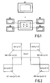
- Demultiplexing the video signal into four adjacent quadrants as disclosed in Research Disclosure, September 1991, 643, item 32903, is another example. It operates in the two dimensional spatial domain. This demultiplexing can be beneficially used for HD applications. Dividing the HD field into four ND fields as illustrated in Fig. 1, the HD signal can be split into four ND channels A,B,C,D, each of which being in accordance with the CCIR recommendations 601 and 656. For instance, this demultiplexing has been employed for the HD digital recording with four ND digital recorders. In general the four quadrants demultiplexing provides the advantage of using ND systems for HD applications. As is well known, an HD frame comprises 1250 lines of 1728 pixels, of which only an active part of 1152 lines of 1440 pixels contains vision information.
- the invention relates to the application of the four quadrants demultiplexing technique to the hardware which for the first time implements the above-mentioned motion estimation algorithm of EP-A-0,415,491 (PHN 13,068) for HD motion estimation.
- the application of the four quadrants demultiplexing technique to motion estimation is new and benefits from the above-mentioned advantages of lower speed in the digital signal processing operations and simpler realization with existing ND modules.
- devices intended for ND motion estimation may also be used for HD motion estimation.
- the vector v(x,y,t) estimated at the time t for the block at the spatial position (x,y) depends on the left and right spatial prediction vectors v(x ⁇ 1,y-1,t) VLS and VRS calculated for the present field and on the left and right temporal prediction vectors v(x ⁇ 2,y+2,t-1) VLT and VRT calculated for the previous field. Every estimated vector depends on previous estimations at different spatial positions, so that on the borders, every quadrant needs output data from another quadrant.
- the present invention provides the solution to this new problem. The problem is solved by opening the prediction loops of the ND motion estimator shown in Fig. 3A and by linking four of these ND motion estimators as shown in Fig. 3B. In the example of Fig.
- the prediction loops of the ND motion estimator are opened after the feedback delays, but alternatively, these loops can be opened before the feedback delays. Opening the prediction loops after the feedback delays allows for a very simple and straightforward implementation of the feedback loops linking as is shown in more detail in the embodiment of Fig. 4. By linking the four ND motion estimators operating for the four quadrants as shown in Fig. 3B, the predictions are available for every ND motion estimator.
- the input video signal is applied to a vector estimation block 301.
- An output of the vector estimation block 301 is coupled to four feedback delays 303, 305, 307, 309 respectively delaying by one line period plus one block period (1L + 1BL), which yields the left spatial prediction VLS shown in Fig. 2, by one line period minus one block period (1L - 1BL), which yields the right spatial prediction VRS shown in Fig. 2, by one field period minus two line periods minus two block periods (1F - 2L - 2BL), which yields the right temporal prediction VRT shown in Fig.
- a block comprises n video lines
- a line period in the sense as described above has a duration which is such that the vector of the block above the present block is obtained, i.e. a line period corresponds to n times a video line period.
- Outputs of the four feedback delays are coupled to corresponding inputs of the vector estimation block 301.
- each ND motion estimator 311 receives the input video signal of the corresponding quadrant.
- Each ND motion estimator 311 furnishes its predictions to a four quadrants prediction link block 313, which in its turn, furnishes predictions from the other three ND motion estimators. With proper control signals, the predictions coming from the other quadrants are selected when they are not available in the same quadrant. In order to guarantee the synchronization of the predictions at the input of the selectors, proper time shifts of the quadrants are necessary.
- Fig. 4 shows a detailed block diagram of an example of a recursive HD motion estimator which is composed of four linked ND motion estimators A, B, C, D and satisfies the proper synchronization criterion.
- the lower quadrants C and D are processed one active field later than the upper quadrants A and B.
- the right quadrants B and D are processed one active line later than the left quadrants A and C.
- the four quadrants demultiplexer 4Q-DMPX can be realized with a buffer memory, so the time shifts of the quadrants can be arranged by reading the quadrants with proper delays.
- Each of these ND motion vector estimators comprises a vector estimation block 401 furnishing an output motion vector to a four quadrants multiplexer 4Q-MPX.
- the output of the vector estimation block 401 is coupled to four feedback delays 403, 405, 407, 409 respectively delaying by one line period plus one block period (1L + 1BL), which yields the left spatial prediction VLS shown in Fig. 2, by one line period minus one block period (1L - 1BL), which yields the right spatial prediction VRS shown in Fig.
- a line period in the sense as described above has a duration which is such that the vector of the block above the present block is obtained, i.e. a line period corresponds to n times a video line period.
- Outputs of the four feedback delays 403, 405, 407, 409 are coupled to corresponding inputs of the vector estimation blocks 401 either directly or through selectors.
- Fig. 5 shows a block diagram of an HD motion compensated upconverter or field number doubler, in which the four quadrants motion estimator cooperates with a four quadrants motion compensated interpolation circuit.
- a receiver circuit 501 supplies a luminance signal to a four quadrants demultiplexer 503 like the four quadrants demultiplexer 4Q-DMPX of Fig. 4.
- This four quadrants demultiplexer 503 furnishes the video signals of the four quadrants to four ND motion vector estimators 511A, 511B, 511C, 511D which interchange predictions with a four quadrants predictions link block 513.
- the four quadrants' video signals from the demultiplexer 503 and the motion vectors from the ND motion vector estimators 511A, 511B, 511C, 511D are applied to an HD interpolator which comprises four parallel ND luminance interpolators 505A, 505B, 505C, 505D which each interpolate one of the four quadrants. Outputs of these four interpolators 505A, 505B, 505C, 505D are multiplexed by a four quadrants multiplexer 507.
- the chrominance signal from the receiver circuit 501 is interpolated in an HD chrominance interpolator 509. Outputs of the HD chrominance interpolator 509 and of the multiplexer 507 are applied to a matrix circuit 515 which furnishes RGB signals to a monitor 517.
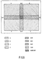
- Fig. 6 shows a preferred manner of demultiplexing the incoming HD video signal to obtain such an overlap. This overlapping demultiplexing is used in the four quadrants demultiplexers 4Q-DMPX and 503 of Figs. 4 and 5.
Description
- The invention relates to a recursive video signal processor of the type suitable for motion vector estimation or noise reduction.
- European patent application EP-A-0,415,491 (PHN 13,068) describes a recursive video signal processing algorithm for such a recursive video signal processor. Whereas the motion vector estimation algorithm described in said document operates satisfactorily, some problems occur in the hardware design of a motion vector estimator using this algorithm for high definition television (HD) applications.
- The video information related to high definition television is four times the video information related to normal definition television (ND). The line number per frame is doubled from 625 to 1250. The pixel number per line is doubled from 864 to 1728. This means that, with the same frame period, the clock frequency of high definition television is four times the clock frequency of normal definition television. The CCIR recommends a luminance sample frequency of 13.5 MHz for normal definition television. In high definition television the luminance sample frequency will be 54 MHz.
- The increased video information and the increased sample frequency result in digital signal processing problems. Current technology does not yet provide an effective digital signal processing for this data rate.
- It is noted that the article "A Real-Time HDTV Signal Processor: HD-VSP", published in IEEE transactions on circuits and systems for video technology, March 1991, Vol. 1, No. 1, pp. 35-41, discloses a programmable real-time HDTV signal processor, in which in order to expand the flexibility, eight video signal processor (VSP) clusters and programmable time-expansion/compression units are employed. An input HDTV signal is converted to eight horizontally adjacent time-expanded sub-regional signals, to reduce their sampling rate to that of conventional TV signals. The converted signals are then processed by the eight clusters in the same manner as the VSP. Processed signals obtained from the eight clusters are time-compressed and multiplexed to reconstruct an output HDTV signal. In a basic VSP configuration, video signal processor modules are connected in parallel to input, output and feedback video buses. A variable delay unit (VDU) is employed in the feedback bus. It achieves a delay of up to one frame on feedback data. In the time-expansion/compression process employed in the HD-VSP, HDTV frame data is divided into overlapping columns. Input and feedback bus switch units (BSU) are used for inter-cluster overlap-add/save implementation.
- This known device is not capable to handle video signal sections which are both horizontally and vertically adjacent to each other. Although the variable delay unit (VDU) provides a variable delay, it is still only one delay period, and the publication does not give any indication on how to handle recursive video signal processing operations which require a plurality of feedback signals which have underwent mutually different delays.
- It is, inter alia, a main object of the invention to provide a recursive video signal processor which can cope with the high data rates involved in high definition television.
- For this purpose, one aspect of the invention provides a recursive video signal processor as set out in
claim 1. Advantageous embodiments of the invention are set out in the subclaims. - These and other aspects of the invention will be apparent from and elucidated with reference to the embodiments described hereinafter.
- In the drawings:
- Fig. 1 shows the demultiplexing of a high definition (HD) video signal into four spatially adjacent quadrants;
- Fig. 2 shows the spatial location of spatial and temporal prediction vectors for the recursive motion vector estimator of the present invention;
- Fig. 3A shows a block diagram of a normal definition (ND) recursive motion estimator having four prediction loops and where these loops can be opened for linking with other motion estimators;
- Fig. 3B shows a block diagram of a HD motion estimator comprising four ND motion estimators having linked prediction loops;
- Fig. 4 shows a block diagram of the HD motion estimator operating with four quadrants;
- Fig. 5 shows the four quadrants motion estimator cooperating with a four quadrants interpolator; and
- Fig. 6 shows the overlap of the four quadrants.
- The invention is based on the recognition that in view of the high data rates involved in, for example, high definition (HD) television, it is worthwhile to parallelize the high speed path into more paths at lower speed. A demultiplexer and a multiplexer are necessary for this purpose. This (de)multiplexing operation can be arranged in many ways: the video signal is a three-dimensional signal, so in general the signal can be demultiplexed in a three- dimensional domain. Typical examples are:
- . pixel demultiplexing along the horizontal domain,
- . line demultiplexing along the vertical domain, and
- . field demultiplexing along the time domain.
- Demultiplexing the video signal into four adjacent quadrants as disclosed in Research Disclosure, September 1991, 643, item 32903, is another example. It operates in the two dimensional spatial domain. This demultiplexing can be beneficially used for HD applications. Dividing the HD field into four ND fields as illustrated in Fig. 1, the HD signal can be split into four ND channels A,B,C,D, each of which being in accordance with the CCIR recommendations 601 and 656. For instance, this demultiplexing has been employed for the HD digital recording with four ND digital recorders. In general the four quadrants demultiplexing provides the advantage of using ND systems for HD applications. As is well known, an HD frame comprises 1250 lines of 1728 pixels, of which only an active part of 1152 lines of 1440 pixels contains vision information.
- The invention relates to the application of the four quadrants demultiplexing technique to the hardware which for the first time implements the above-mentioned motion estimation algorithm of EP-A-0,415,491 (PHN 13,068) for HD motion estimation. The application of the four quadrants demultiplexing technique to motion estimation is new and benefits from the above-mentioned advantages of lower speed in the digital signal processing operations and simpler realization with existing ND modules. In future, devices intended for ND motion estimation may also be used for HD motion estimation.
- The application of the four quadrants demultiplexing technique to the HD recursive search motion estimation is not trivial. The problem is that an HD motion estimation cannot be performed with four ND estimators independently working in parallel. The reason for this problem is that in a preferred embodiment of the motion vector estimation algorithm described in more detail in the above-mentioned European patent application EP-A-0,415,491 (PHN 13,068) and illustrated in Fig. 2, the vector v(x,y,t) estimated at the time t for the block at the spatial position (x,y) depends on the left and right spatial prediction vectors v(x±1,y-1,t) VLS and VRS calculated for the present field and on the left and right temporal prediction vectors v(x±2,y+2,t-1) VLT and VRT calculated for the previous field. Every estimated vector depends on previous estimations at different spatial positions, so that on the borders, every quadrant needs output data from another quadrant. The present invention provides the solution to this new problem. The problem is solved by opening the prediction loops of the ND motion estimator shown in Fig. 3A and by linking four of these ND motion estimators as shown in Fig. 3B. In the example of Fig. 3A, the prediction loops of the ND motion estimator are opened after the feedback delays, but alternatively, these loops can be opened before the feedback delays. Opening the prediction loops after the feedback delays allows for a very simple and straightforward implementation of the feedback loops linking as is shown in more detail in the embodiment of Fig. 4. By linking the four ND motion estimators operating for the four quadrants as shown in Fig. 3B, the predictions are available for every ND motion estimator.
- In the ND motion vector estimator shown in Fig. 3A, the input video signal is applied to a
vector estimation block 301. An output of thevector estimation block 301 is coupled to fourfeedback delays vector estimation block 301. - In the block diagram of Fig. 3B, which shows an HD motion estimator composed of four ND motion estimators each processing one of the four quadrants shown in Fig. 1, each ND motion estimator 311 receives the input video signal of the corresponding quadrant. Each ND motion estimator 311 furnishes its predictions to a four quadrants
prediction link block 313, which in its turn, furnishes predictions from the other three ND motion estimators. With proper control signals, the predictions coming from the other quadrants are selected when they are not available in the same quadrant. In order to guarantee the synchronization of the predictions at the input of the selectors, proper time shifts of the quadrants are necessary. - Fig. 4 shows a detailed block diagram of an example of a recursive HD motion estimator which is composed of four linked ND motion estimators A, B, C, D and satisfies the proper synchronization criterion. The lower quadrants C and D are processed one active field later than the upper quadrants A and B. The right quadrants B and D are processed one active line later than the left quadrants A and C. The four quadrants demultiplexer 4Q-DMPX can be realized with a buffer memory, so the time shifts of the quadrants can be arranged by reading the quadrants with proper delays. Four outputs of the
demultiplexer 4Q-DMPX are coupled to four respective recursive ND motion vector estimators A, B, C, D, which parallel-process the four quadrants into which the input video signal is divided. Each of these ND motion vector estimators comprises a vector estimation block 401 furnishing an output motion vector to a four quadrants multiplexer 4Q-MPX. Inside each ND motion vector estimator, the output of the vector estimation block 401 is coupled to four feedback delays 403, 405, 407, 409 respectively delaying by one line period plus one block period (1L + 1BL), which yields the left spatial prediction VLS shown in Fig. 2, by one line period minus one block period (1L - 1BL), which yields the right spatial prediction VRS shown in Fig. 2, by one field period minus two line periods minus two block periods (1F - 2L - 2BL), which yields the right temporal prediction VRT shown in Fig. 2, and by one field period minus two line periods plus two block periods (1F -2L + 2BL), which yields the left temporal prediction VLT shown in Fig. 2. Again, if a block comprises n video lines, a line period in the sense as described above has a duration which is such that the vector of the block above the present block is obtained, i.e. a line period corresponds to n times a video line period. Outputs of the four feedback delays 403, 405, 407, 409 are coupled to corresponding inputs of the vector estimation blocks 401 either directly or through selectors. - In the left upper ND motion vector estimator A, there will be no left spatial prediction VLS from an adjacent quadrant, so that the output of the
feedback delay 403A furnishing the VLS prediction is directly coupled to the vector estimation block. However, there might be a need for a right spatial prediction VRS from quadrant B, a right temporal prediction VRT from quadrants B, C or D, and a left temporal prediction VLT from quadrant C. Therefore, threeselectors vector estimation block 401A of ND motion vector estimator A. - In a similar manner, in the upper right ND motion vector estimator B, there will be no right spatial prediction VRS from an adjacent quadrant, so that the output of the feedback delay 405B furnishing the VRS prediction is directly coupled to the
vector estimation block 401B. However, there might be a need for a left spatial prediction VLS from quadrant A, a right temporal prediction VRT from quadrant D, and a left temporal prediction VLT from quadrants A, C or D. Therefore, threeselectors vector estimation block 401B of ND motion vector estimator B. - Similarly, in the lower left ND motion vector estimator C, there will be no left temporal prediction VLT from an adjacent quadrant, so that the output of the
feedback delay 409C furnishing the VLT prediction is directly coupled to the vector estimation block 401C. However, there might be a need for a left spatial prediction VLS from quadrant A, a right temporal prediction VRT from quadrant D, and a right spatial prediction VRS from quadrants A, B or D. Therefore, threeselectors - And finally, in the lower right ND motion vector estimator D, there will be no right temporal prediction VRT from an adjacent quadrant, so that the output of the feedback delay 407D furnishing the VRT prediction is directly coupled to the vector estimation block 401D. However, there might be a need for a left spatial prediction VLS from quadrants A, B or C, a right spatial prediction VRS from quadrant B, and a left temporal prediction VLT from quadrant C. Therefore, three selectors 415D, 417D, 419D switch the required predictions VLS, VRS and VLT from the present quadrant D or from one of the adjacent quadrants A,B,C to the vector estimation block 401D of ND motion vector estimator D.
- Fig. 5 shows a block diagram of an HD motion compensated upconverter or field number doubler, in which the four quadrants motion estimator cooperates with a four quadrants motion compensated interpolation circuit. A
receiver circuit 501 supplies a luminance signal to a fourquadrants demultiplexer 503 like the four quadrants demultiplexer 4Q-DMPX of Fig. 4. This fourquadrants demultiplexer 503 furnishes the video signals of the four quadrants to four NDmotion vector estimators block 513. The four quadrants' video signals from thedemultiplexer 503 and the motion vectors from the NDmotion vector estimators ND luminance interpolators interpolators quadrants multiplexer 507. The chrominance signal from thereceiver circuit 501 is interpolated in anHD chrominance interpolator 509. Outputs of theHD chrominance interpolator 509 and of themultiplexer 507 are applied to amatrix circuit 515 which furnishes RGB signals to amonitor 517. - The recursive estimation which involves predictions at different spatial positions is not present in the interpolation circuit, so that there is no need for a link of the four quadrants in the interpolation circuit. But another problem occurs in the four quadrants demultiplexing of the interpolation circuit, which problem is common to the motion estimator and the interpolation circuit. In both parts of the upconverter, there are operations like vector shifts or FIR filtering operations, in which the output depends on the input evaluated at different spatial positions, thus requiring data from the other quadrants. For these operations, there is no need for a link as described above, but an appropriate overlap of the four quadrants is sufficient to solve the problem. Fig. 6 shows a preferred manner of demultiplexing the incoming HD video signal to obtain such an overlap. This overlapping demultiplexing is used in the four quadrants demultiplexers 4Q-DMPX and 503 of Figs. 4 and 5.
- It will be evident that on the basis of the examples described above, the man skilled in the art will be able to design many alternative embodiments all falling within the scope of this invention as defined by the following claims.
Claims (3)
- A recursive video signal processor, comprising:means (4Q-DMPX) for demultiplexing a video signal into a plurality of horizontally and vertically adjacent sections (A,B,C,D), wherein said demultiplexing means (4Q-DMPX) comprise delay means for delaying video signals applied to horizontally adjacent sections (A,B; C,D) by one line period with respect to each other and for delaying video signals applied to vertically adjacent sections (A,C; B,D) by one field period with respect to each other;a plurality of parallel video signal processing means (301) coupled to respective outputs of said demultiplexing means (4Q-DMPX), each one of said video signal processing means (301) recursively processing one of said horizontally and vertically adjacent sections (A,B,C,D) by means of a plurality of feedback loops (303-309) having mutually different feedback delay periods; andlink means (313) for providing a mutual selective coupling of respective predetermined ones of said plurality of mutually different feedback loops (303-309) of said plurality of parallel video signal processing means (301), to apply to each one of said parallel video signal processing means (301), data from at least one other video signal processing means.
- A recursive video signal processor as claimed in Claim 1, wherein each one of said video signal processing means comprise a plurality of spatial and/or temporal feedback delay means (403A-409A) coupled to an output of the relevant video signal processing means (401A), and wherein said link means comprise a plurality of selector means (415-419) each for selectively coupling outputs of respective predetermined ones of said feedback delay means (403A-409A) of several video signal processing means (401A, 401B, 401C, 401D) including the relevant video signal processing means (401A), to inputs of the relevant video signal processing means (401A).
- A recursive video signal processor as claimed in Claim 1, wherein said horizontally and vertically adjacent sections (A,B,C,D) partially overlap.
Applications Claiming Priority (4)
| Application Number | Priority Date | Filing Date | Title |
|---|---|---|---|
| EP91203398 | 1991-12-23 | ||
| EP91203398 | 1991-12-23 | ||
| ITMI920302 | 1992-02-13 | ||
| ITMI920302A IT1254787B (en) | 1992-02-13 | 1992-02-13 | Recursive video signal processor |
Publications (3)
| Publication Number | Publication Date |
|---|---|
| EP0554586A2 EP0554586A2 (en) | 1993-08-11 |
| EP0554586A3 EP0554586A3 (en) | 1993-12-01 |
| EP0554586B1 true EP0554586B1 (en) | 1997-03-19 |
Family
ID=26129530
Family Applications (1)
| Application Number | Title | Priority Date | Filing Date |
|---|---|---|---|
| EP92203951A Expired - Lifetime EP0554586B1 (en) | 1991-12-23 | 1992-12-16 | Recursive video signal processor |
Country Status (5)
| Country | Link |
|---|---|
| EP (1) | EP0554586B1 (en) |
| JP (1) | JPH05276492A (en) |
| KR (1) | KR100254956B1 (en) |
| DE (1) | DE69218396T2 (en) |
| FI (1) | FI925783A (en) |
Cited By (26)
| Publication number | Priority date | Publication date | Assignee | Title |
|---|---|---|---|---|
| DE102008034495A1 (en) * | 2008-07-24 | 2010-01-28 | Trident Microsystems (Far East) Ltd. | Input video signal processing method, involves providing two partial images by motion-compensated interpolation of two images of input image sequence, and producing output image from two partial images |
| US8246470B2 (en) | 2002-12-10 | 2012-08-21 | Onlive, Inc. | Mass storage repository for a wireless network |
| US8366552B2 (en) | 2002-12-10 | 2013-02-05 | Ol2, Inc. | System and method for multi-stream video compression |
| US8387099B2 (en) | 2002-12-10 | 2013-02-26 | Ol2, Inc. | System for acceleration of web page delivery |
| US8468575B2 (en) | 2002-12-10 | 2013-06-18 | Ol2, Inc. | System for recursive recombination of streaming interactive video |
| US8495678B2 (en) | 2002-12-10 | 2013-07-23 | Ol2, Inc. | System for reporting recorded video preceding system failures |
| US8526490B2 (en) | 2002-12-10 | 2013-09-03 | Ol2, Inc. | System and method for video compression using feedback including data related to the successful receipt of video content |
| US8549574B2 (en) | 2002-12-10 | 2013-10-01 | Ol2, Inc. | Method of combining linear content and interactive content compressed together as streaming interactive video |
| US8606942B2 (en) | 2002-12-10 | 2013-12-10 | Ol2, Inc. | System and method for intelligently allocating client requests to server centers |
| US8661496B2 (en) | 2002-12-10 | 2014-02-25 | Ol2, Inc. | System for combining a plurality of views of real-time streaming interactive video |
| US8711923B2 (en) | 2002-12-10 | 2014-04-29 | Ol2, Inc. | System and method for selecting a video encoding format based on feedback data |
| US8832772B2 (en) | 2002-12-10 | 2014-09-09 | Ol2, Inc. | System for combining recorded application state with application streaming interactive video output |
| US8840475B2 (en) | 2002-12-10 | 2014-09-23 | Ol2, Inc. | Method for user session transitioning among streaming interactive video servers |
| US8893207B2 (en) | 2002-12-10 | 2014-11-18 | Ol2, Inc. | System and method for compressing streaming interactive video |
| US8949922B2 (en) | 2002-12-10 | 2015-02-03 | Ol2, Inc. | System for collaborative conferencing using streaming interactive video |
| US8964830B2 (en) | 2002-12-10 | 2015-02-24 | Ol2, Inc. | System and method for multi-stream video compression using multiple encoding formats |
| US9003461B2 (en) | 2002-12-10 | 2015-04-07 | Ol2, Inc. | Streaming interactive video integrated with recorded video segments |
| US9032465B2 (en) | 2002-12-10 | 2015-05-12 | Ol2, Inc. | Method for multicasting views of real-time streaming interactive video |
| US9061207B2 (en) | 2002-12-10 | 2015-06-23 | Sony Computer Entertainment America Llc | Temporary decoder apparatus and method |
| US9077991B2 (en) | 2002-12-10 | 2015-07-07 | Sony Computer Entertainment America Llc | System and method for utilizing forward error correction with video compression |
| US9084936B2 (en) | 2002-12-10 | 2015-07-21 | Sony Computer Entertainment America Llc | System and method for protecting certain types of multimedia data transmitted over a communication channel |
| US9138644B2 (en) | 2002-12-10 | 2015-09-22 | Sony Computer Entertainment America Llc | System and method for accelerated machine switching |
| US9168457B2 (en) | 2010-09-14 | 2015-10-27 | Sony Computer Entertainment America Llc | System and method for retaining system state |
| US9192859B2 (en) | 2002-12-10 | 2015-11-24 | Sony Computer Entertainment America Llc | System and method for compressing video based on latency measurements and other feedback |
| US9314691B2 (en) | 2002-12-10 | 2016-04-19 | Sony Computer Entertainment America Llc | System and method for compressing video frames or portions thereof based on feedback information from a client device |
| US9446305B2 (en) | 2002-12-10 | 2016-09-20 | Sony Interactive Entertainment America Llc | System and method for improving the graphics performance of hosted applications |
Families Citing this family (11)
| Publication number | Priority date | Publication date | Assignee | Title |
|---|---|---|---|---|
| DE69429760T2 (en) * | 1993-10-27 | 2002-08-08 | Texas Instruments Inc | Method and device for packing data into an image processor |
| FR2711877B1 (en) * | 1993-10-29 | 1996-02-02 | Sgs Thomson Microelectronics | High definition image processing system. |
| US6104751A (en) * | 1993-10-29 | 2000-08-15 | Sgs-Thomson Microelectronics S.A. | Apparatus and method for decompressing high definition pictures |
| US5485215A (en) * | 1994-05-19 | 1996-01-16 | Matsushita Electric Corporation Of America | HDTV raster converter and interpolation filter with section overlap |
| US5990939A (en) * | 1995-09-28 | 1999-11-23 | Raytheon Company | Video demultiplexing interface for a missile tracking system |
| EP0778698B1 (en) * | 1995-12-06 | 2001-09-12 | THOMSON multimedia | Method and apparatus for fine motion estimation in digital video pictures |
| GB9620162D0 (en) * | 1996-09-27 | 1996-11-13 | Digi Media Vision Ltd | Method and apparatus for generating signals including predicted code |
| US10201760B2 (en) | 2002-12-10 | 2019-02-12 | Sony Interactive Entertainment America Llc | System and method for compressing video based on detected intraframe motion |
| US8382591B2 (en) | 2010-06-03 | 2013-02-26 | Ol2, Inc. | Graphical user interface, system and method for implementing a game controller on a touch-screen device |
| US8591334B2 (en) | 2010-06-03 | 2013-11-26 | Ol2, Inc. | Graphical user interface, system and method for implementing a game controller on a touch-screen device |
| JP6268066B2 (en) * | 2013-09-20 | 2018-01-24 | パナソニック インテレクチュアル プロパティ コーポレーション オブ アメリカPanasonic Intellectual Property Corporation of America | Transmission method, reception method, transmission device, and reception device |
Family Cites Families (5)
| Publication number | Priority date | Publication date | Assignee | Title |
|---|---|---|---|---|
| US4218703A (en) * | 1979-03-16 | 1980-08-19 | Bell Telephone Laboratories, Incorporated | Technique for estimation of displacement and/or velocity of objects in video scenes |
| DE3578298D1 (en) * | 1984-07-20 | 1990-07-19 | Nec Corp | REAL-TIME PROCESSING SYSTEM FOR VIDEO SIGNALS. |
| CA1267970A (en) * | 1986-06-10 | 1990-04-17 | Ichiro Tamitani | Real-time video signal processing device capable of typically executing interframe coding |
| KR920006283B1 (en) * | 1988-02-19 | 1992-08-03 | 미쯔비시덴끼 가부시끼가이샤 | Digital signal processing method |
| US5072293A (en) * | 1989-08-29 | 1991-12-10 | U.S. Philips Corporation | Method of estimating motion in a picture signal |
-
1992
- 1992-12-14 KR KR1019920024119A patent/KR100254956B1/en not_active IP Right Cessation
- 1992-12-16 EP EP92203951A patent/EP0554586B1/en not_active Expired - Lifetime
- 1992-12-16 DE DE69218396T patent/DE69218396T2/en not_active Expired - Fee Related
- 1992-12-18 FI FI925783A patent/FI925783A/en not_active Application Discontinuation
- 1992-12-21 JP JP4340682A patent/JPH05276492A/en active Pending
Cited By (34)
| Publication number | Priority date | Publication date | Assignee | Title |
|---|---|---|---|---|
| US8893207B2 (en) | 2002-12-10 | 2014-11-18 | Ol2, Inc. | System and method for compressing streaming interactive video |
| US8526490B2 (en) | 2002-12-10 | 2013-09-03 | Ol2, Inc. | System and method for video compression using feedback including data related to the successful receipt of video content |
| US8246470B2 (en) | 2002-12-10 | 2012-08-21 | Onlive, Inc. | Mass storage repository for a wireless network |
| US8366552B2 (en) | 2002-12-10 | 2013-02-05 | Ol2, Inc. | System and method for multi-stream video compression |
| US9446305B2 (en) | 2002-12-10 | 2016-09-20 | Sony Interactive Entertainment America Llc | System and method for improving the graphics performance of hosted applications |
| US8468575B2 (en) | 2002-12-10 | 2013-06-18 | Ol2, Inc. | System for recursive recombination of streaming interactive video |
| US8495678B2 (en) | 2002-12-10 | 2013-07-23 | Ol2, Inc. | System for reporting recorded video preceding system failures |
| US8949922B2 (en) | 2002-12-10 | 2015-02-03 | Ol2, Inc. | System for collaborative conferencing using streaming interactive video |
| US8549574B2 (en) | 2002-12-10 | 2013-10-01 | Ol2, Inc. | Method of combining linear content and interactive content compressed together as streaming interactive video |
| US8953675B2 (en) | 2002-12-10 | 2015-02-10 | Ol2, Inc. | Tile-based system and method for compressing video |
| US8661496B2 (en) | 2002-12-10 | 2014-02-25 | Ol2, Inc. | System for combining a plurality of views of real-time streaming interactive video |
| US8711923B2 (en) | 2002-12-10 | 2014-04-29 | Ol2, Inc. | System and method for selecting a video encoding format based on feedback data |
| US8769594B2 (en) | 2002-12-10 | 2014-07-01 | Ol2, Inc. | Video compression system and method for reducing the effects of packet loss over a communication channel |
| US8832772B2 (en) | 2002-12-10 | 2014-09-09 | Ol2, Inc. | System for combining recorded application state with application streaming interactive video output |
| US8840475B2 (en) | 2002-12-10 | 2014-09-23 | Ol2, Inc. | Method for user session transitioning among streaming interactive video servers |
| US8881215B2 (en) | 2002-12-10 | 2014-11-04 | Ol2, Inc. | System and method for compressing video based on detected data rate of a communication channel |
| US8387099B2 (en) | 2002-12-10 | 2013-02-26 | Ol2, Inc. | System for acceleration of web page delivery |
| US9420283B2 (en) | 2002-12-10 | 2016-08-16 | Sony Interactive Entertainment America Llc | System and method for selecting a video encoding format based on feedback data |
| US8606942B2 (en) | 2002-12-10 | 2013-12-10 | Ol2, Inc. | System and method for intelligently allocating client requests to server centers |
| US8964830B2 (en) | 2002-12-10 | 2015-02-24 | Ol2, Inc. | System and method for multi-stream video compression using multiple encoding formats |
| US9003461B2 (en) | 2002-12-10 | 2015-04-07 | Ol2, Inc. | Streaming interactive video integrated with recorded video segments |
| US9032465B2 (en) | 2002-12-10 | 2015-05-12 | Ol2, Inc. | Method for multicasting views of real-time streaming interactive video |
| US9061207B2 (en) | 2002-12-10 | 2015-06-23 | Sony Computer Entertainment America Llc | Temporary decoder apparatus and method |
| US9077991B2 (en) | 2002-12-10 | 2015-07-07 | Sony Computer Entertainment America Llc | System and method for utilizing forward error correction with video compression |
| US9084936B2 (en) | 2002-12-10 | 2015-07-21 | Sony Computer Entertainment America Llc | System and method for protecting certain types of multimedia data transmitted over a communication channel |
| US9108107B2 (en) | 2002-12-10 | 2015-08-18 | Sony Computer Entertainment America Llc | Hosting and broadcasting virtual events using streaming interactive video |
| US9138644B2 (en) | 2002-12-10 | 2015-09-22 | Sony Computer Entertainment America Llc | System and method for accelerated machine switching |
| US9155962B2 (en) | 2002-12-10 | 2015-10-13 | Sony Computer Entertainment America Llc | System and method for compressing video by allocating bits to image tiles based on detected intraframe motion or scene complexity |
| US9314691B2 (en) | 2002-12-10 | 2016-04-19 | Sony Computer Entertainment America Llc | System and method for compressing video frames or portions thereof based on feedback information from a client device |
| US9192859B2 (en) | 2002-12-10 | 2015-11-24 | Sony Computer Entertainment America Llc | System and method for compressing video based on latency measurements and other feedback |
| US9272209B2 (en) | 2002-12-10 | 2016-03-01 | Sony Computer Entertainment America Llc | Streaming interactive video client apparatus |
| DE102008034495B4 (en) * | 2008-07-24 | 2010-11-25 | Trident Microsystems (Far East) Ltd. | Method and device for increasing the frame rate of an image sequence |
| DE102008034495A1 (en) * | 2008-07-24 | 2010-01-28 | Trident Microsystems (Far East) Ltd. | Input video signal processing method, involves providing two partial images by motion-compensated interpolation of two images of input image sequence, and producing output image from two partial images |
| US9168457B2 (en) | 2010-09-14 | 2015-10-27 | Sony Computer Entertainment America Llc | System and method for retaining system state |
Also Published As
| Publication number | Publication date |
|---|---|
| KR100254956B1 (en) | 2002-12-18 |
| JPH05276492A (en) | 1993-10-22 |
| FI925783A0 (en) | 1992-12-18 |
| EP0554586A2 (en) | 1993-08-11 |
| DE69218396T2 (en) | 1997-09-04 |
| EP0554586A3 (en) | 1993-12-01 |
| FI925783A (en) | 1993-06-24 |
| DE69218396D1 (en) | 1997-04-24 |
Similar Documents
| Publication | Publication Date | Title |
|---|---|---|
| EP0554586B1 (en) | Recursive video signal processor | |
| US4965667A (en) | Method and apparatus for processing signals conveyed in sub-sampled form by way of a transmission channel or record carrier | |
| US5689305A (en) | System for deinterlacing digitally compressed video and method | |
| EP0577165B1 (en) | Motion-compensated picture signal interpolation | |
| KR100426889B1 (en) | A self-moving image scanning format converter with seamless switching | |
| US5043810A (en) | Method and apparatus for temporally and spatially processing a video signal | |
| US4862266A (en) | Television standards converters | |
| EP0626788B1 (en) | Video images decoder architecture for implementing a 40 ms processing algorithm in high definition televisions | |
| JPH08510880A (en) | Method and apparatus for motion compensated interpolation | |
| KR0140674B1 (en) | Method for image signal processing | |
| EP0703704B1 (en) | Half-pixel motion compensation controller accepting MPEG2 | |
| US5386248A (en) | Method and apparatus for reducing motion estimator hardware and data transmission capacity requirements in video systems | |
| US4543607A (en) | Video processors | |
| US5469214A (en) | Device for recursive processing of a video signal, comprising a plurality of branches | |
| US5495296A (en) | Digital signal processing circuit for filtering an image signal vertically | |
| US6023718A (en) | High speed interpolation filter and a method thereof | |
| US5495293A (en) | Frame synchronizer and a signal switching apparatus | |
| GB2281835A (en) | Phase locking system for video signals | |
| EP1272939B1 (en) | Elementary cell of a linear filter for image processing | |
| US5262857A (en) | Still-image video signal processing circuit | |
| KR19990080824A (en) | Apparatus and method for converting video format using common format | |
| Nishitani et al. | A real-time software programmable processor for HDTV and stereo scope signals | |
| KR960006760B1 (en) | Sample supplying apparatus for hd-mac decoder | |
| EP0474272B1 (en) | Method and apparatus for reducing motion estimator hardware and data transmission capacity requirements in video systems | |
| AU7239691A (en) | Hd-mac television decoder |
Legal Events
| Date | Code | Title | Description |
|---|---|---|---|
| PUAI | Public reference made under article 153(3) epc to a published international application that has entered the european phase |
Free format text: ORIGINAL CODE: 0009012 |
|
| AK | Designated contracting states |
Kind code of ref document: A2 Designated state(s): DE FR GB IT |
|
| PUAL | Search report despatched |
Free format text: ORIGINAL CODE: 0009013 |
|
| AK | Designated contracting states |
Kind code of ref document: A3 Designated state(s): DE FR GB IT |
|
| 17P | Request for examination filed |
Effective date: 19940530 |
|
| 17Q | First examination report despatched |
Effective date: 19941215 |
|
| GRAG | Despatch of communication of intention to grant |
Free format text: ORIGINAL CODE: EPIDOS AGRA |
|
| GRAH | Despatch of communication of intention to grant a patent |
Free format text: ORIGINAL CODE: EPIDOS IGRA |
|
| GRAH | Despatch of communication of intention to grant a patent |
Free format text: ORIGINAL CODE: EPIDOS IGRA |
|
| GRAA | (expected) grant |
Free format text: ORIGINAL CODE: 0009210 |
|
| AK | Designated contracting states |
Kind code of ref document: B1 Designated state(s): DE FR GB IT |
|
| PG25 | Lapsed in a contracting state [announced via postgrant information from national office to epo] |
Ref country code: IT Free format text: LAPSE BECAUSE OF FAILURE TO SUBMIT A TRANSLATION OF THE DESCRIPTION OR TO PAY THE FEE WITHIN THE PRESCRIBED TIME-LIMIT;WARNING: LAPSES OF ITALIAN PATENTS WITH EFFECTIVE DATE BEFORE 2007 MAY HAVE OCCURRED AT ANY TIME BEFORE 2007. THE CORRECT EFFECTIVE DATE MAY BE DIFFERENT FROM THE ONE RECORDED. Effective date: 19970319 |
|
| REF | Corresponds to: |
Ref document number: 69218396 Country of ref document: DE Date of ref document: 19970424 |
|
| ET | Fr: translation filed | ||
| PLBE | No opposition filed within time limit |
Free format text: ORIGINAL CODE: 0009261 |
|
| STAA | Information on the status of an ep patent application or granted ep patent |
Free format text: STATUS: NO OPPOSITION FILED WITHIN TIME LIMIT |
|
| 26N | No opposition filed | ||
| REG | Reference to a national code |
Ref country code: FR Ref legal event code: CD |
|
| REG | Reference to a national code |
Ref country code: GB Ref legal event code: IF02 |
|
| REG | Reference to a national code |
Ref country code: GB Ref legal event code: 746 Effective date: 20020919 |
|
| REG | Reference to a national code |
Ref country code: FR Ref legal event code: D6 |
|
| PGFP | Annual fee paid to national office [announced via postgrant information from national office to epo] |
Ref country code: FR Payment date: 20021223 Year of fee payment: 11 |
|
| PGFP | Annual fee paid to national office [announced via postgrant information from national office to epo] |
Ref country code: GB Payment date: 20021224 Year of fee payment: 11 |
|
| PGFP | Annual fee paid to national office [announced via postgrant information from national office to epo] |
Ref country code: DE Payment date: 20030217 Year of fee payment: 11 |
|
| PG25 | Lapsed in a contracting state [announced via postgrant information from national office to epo] |
Ref country code: GB Free format text: LAPSE BECAUSE OF NON-PAYMENT OF DUE FEES Effective date: 20031216 |
|
| PG25 | Lapsed in a contracting state [announced via postgrant information from national office to epo] |
Ref country code: DE Free format text: LAPSE BECAUSE OF NON-PAYMENT OF DUE FEES Effective date: 20040701 |
|
| GBPC | Gb: european patent ceased through non-payment of renewal fee |
Effective date: 20031216 |
|
| PG25 | Lapsed in a contracting state [announced via postgrant information from national office to epo] |
Ref country code: FR Free format text: LAPSE BECAUSE OF NON-PAYMENT OF DUE FEES Effective date: 20040831 |
|
| REG | Reference to a national code |
Ref country code: FR Ref legal event code: ST |