EP0558848A2 - Recording medium and system for reproducing recorded information therefrom - Google Patents
Recording medium and system for reproducing recorded information therefrom Download PDFInfo
- Publication number
- EP0558848A2 EP0558848A2 EP92308130A EP92308130A EP0558848A2 EP 0558848 A2 EP0558848 A2 EP 0558848A2 EP 92308130 A EP92308130 A EP 92308130A EP 92308130 A EP92308130 A EP 92308130A EP 0558848 A2 EP0558848 A2 EP 0558848A2
- Authority
- EP
- European Patent Office
- Prior art keywords
- block
- signal
- subblocks
- recording medium
- recorded
- Prior art date
- Legal status (The legal status is an assumption and is not a legal conclusion. Google has not performed a legal analysis and makes no representation as to the accuracy of the status listed.)
- Granted
Links
Images


Classifications
-
- H—ELECTRICITY
- H04—ELECTRIC COMMUNICATION TECHNIQUE
- H04N—PICTORIAL COMMUNICATION, e.g. TELEVISION
- H04N5/00—Details of television systems
- H04N5/76—Television signal recording
- H04N5/91—Television signal processing therefor
- H04N5/92—Transformation of the television signal for recording, e.g. modulation, frequency changing; Inverse transformation for playback
- H04N5/9201—Transformation of the television signal for recording, e.g. modulation, frequency changing; Inverse transformation for playback involving the multiplexing of an additional signal and the video signal
- H04N5/9206—Transformation of the television signal for recording, e.g. modulation, frequency changing; Inverse transformation for playback involving the multiplexing of an additional signal and the video signal the additional signal being a character code signal
- H04N5/9208—Transformation of the television signal for recording, e.g. modulation, frequency changing; Inverse transformation for playback involving the multiplexing of an additional signal and the video signal the additional signal being a character code signal involving the use of subcodes
-
- G—PHYSICS
- G11—INFORMATION STORAGE
- G11B—INFORMATION STORAGE BASED ON RELATIVE MOVEMENT BETWEEN RECORD CARRIER AND TRANSDUCER
- G11B20/00—Signal processing not specific to the method of recording or reproducing; Circuits therefor
- G11B20/10—Digital recording or reproducing
-
- G—PHYSICS
- G11—INFORMATION STORAGE
- G11B—INFORMATION STORAGE BASED ON RELATIVE MOVEMENT BETWEEN RECORD CARRIER AND TRANSDUCER
- G11B20/00—Signal processing not specific to the method of recording or reproducing; Circuits therefor
- G11B20/10—Digital recording or reproducing
- G11B20/12—Formatting, e.g. arrangement of data block or words on the record carriers
- G11B20/1217—Formatting, e.g. arrangement of data block or words on the record carriers on discs
- G11B20/1254—Formatting, e.g. arrangement of data block or words on the record carriers on discs for mixed data, i.e. continuous and discontinuous data
-
- G—PHYSICS
- G11—INFORMATION STORAGE
- G11B—INFORMATION STORAGE BASED ON RELATIVE MOVEMENT BETWEEN RECORD CARRIER AND TRANSDUCER
- G11B27/00—Editing; Indexing; Addressing; Timing or synchronising; Monitoring; Measuring tape travel
- G11B27/10—Indexing; Addressing; Timing or synchronising; Measuring tape travel
- G11B27/102—Programmed access in sequence to addressed parts of tracks of operating record carriers
- G11B27/105—Programmed access in sequence to addressed parts of tracks of operating record carriers of operating discs
-
- G—PHYSICS
- G11—INFORMATION STORAGE
- G11B—INFORMATION STORAGE BASED ON RELATIVE MOVEMENT BETWEEN RECORD CARRIER AND TRANSDUCER
- G11B27/00—Editing; Indexing; Addressing; Timing or synchronising; Monitoring; Measuring tape travel
- G11B27/10—Indexing; Addressing; Timing or synchronising; Measuring tape travel
- G11B27/19—Indexing; Addressing; Timing or synchronising; Measuring tape travel by using information detectable on the record carrier
- G11B27/28—Indexing; Addressing; Timing or synchronising; Measuring tape travel by using information detectable on the record carrier by using information signals recorded by the same method as the main recording
- G11B27/30—Indexing; Addressing; Timing or synchronising; Measuring tape travel by using information detectable on the record carrier by using information signals recorded by the same method as the main recording on the same track as the main recording
- G11B27/3027—Indexing; Addressing; Timing or synchronising; Measuring tape travel by using information detectable on the record carrier by using information signals recorded by the same method as the main recording on the same track as the main recording used signal is digitally coded
-
- H—ELECTRICITY
- H04—ELECTRIC COMMUNICATION TECHNIQUE
- H04N—PICTORIAL COMMUNICATION, e.g. TELEVISION
- H04N5/00—Details of television systems
- H04N5/76—Television signal recording
- H04N5/91—Television signal processing therefor
- H04N5/92—Transformation of the television signal for recording, e.g. modulation, frequency changing; Inverse transformation for playback
- H04N5/926—Transformation of the television signal for recording, e.g. modulation, frequency changing; Inverse transformation for playback by pulse code modulation
- H04N5/9265—Transformation of the television signal for recording, e.g. modulation, frequency changing; Inverse transformation for playback by pulse code modulation with processing of the sound signal
- H04N5/9267—Transformation of the television signal for recording, e.g. modulation, frequency changing; Inverse transformation for playback by pulse code modulation with processing of the sound signal using time division multiplex of the PCM audio and PCM video signals
-
- G—PHYSICS
- G11—INFORMATION STORAGE
- G11B—INFORMATION STORAGE BASED ON RELATIVE MOVEMENT BETWEEN RECORD CARRIER AND TRANSDUCER
- G11B20/00—Signal processing not specific to the method of recording or reproducing; Circuits therefor
- G11B20/10—Digital recording or reproducing
- G11B20/10527—Audio or video recording; Data buffering arrangements
- G11B2020/10537—Audio or video recording
- G11B2020/10592—Audio or video recording specifically adapted for recording or reproducing multichannel signals
-
- G—PHYSICS
- G11—INFORMATION STORAGE
- G11B—INFORMATION STORAGE BASED ON RELATIVE MOVEMENT BETWEEN RECORD CARRIER AND TRANSDUCER
- G11B2220/00—Record carriers by type
- G11B2220/20—Disc-shaped record carriers
- G11B2220/25—Disc-shaped record carriers characterised in that the disc is based on a specific recording technology
- G11B2220/2537—Optical discs
- G11B2220/2545—CDs
- G11B2220/255—CD-I, i.e. CD-interactive
-
- G—PHYSICS
- G11—INFORMATION STORAGE
- G11B—INFORMATION STORAGE BASED ON RELATIVE MOVEMENT BETWEEN RECORD CARRIER AND TRANSDUCER
- G11B27/00—Editing; Indexing; Addressing; Timing or synchronising; Monitoring; Measuring tape travel
- G11B27/10—Indexing; Addressing; Timing or synchronising; Measuring tape travel
- G11B27/19—Indexing; Addressing; Timing or synchronising; Measuring tape travel by using information detectable on the record carrier
- G11B27/28—Indexing; Addressing; Timing or synchronising; Measuring tape travel by using information detectable on the record carrier by using information signals recorded by the same method as the main recording
- G11B27/30—Indexing; Addressing; Timing or synchronising; Measuring tape travel by using information detectable on the record carrier by using information signals recorded by the same method as the main recording on the same track as the main recording
- G11B27/3027—Indexing; Addressing; Timing or synchronising; Measuring tape travel by using information detectable on the record carrier by using information signals recorded by the same method as the main recording on the same track as the main recording used signal is digitally coded
- G11B27/3063—Subcodes
Definitions
- the present invention relates to a recording medium on which multifarious types of digital information signals, such as audio data, video image data and computer data, are to be recorded, and a system for playing this recording medium to reproduce the recorded information.
- CD Compact Disk
- CD-ROM Compact Disk-ROM
- CD-I Compact Disk-Interactive
- Both CD and CD-ROM can construct a large-capacity memory system of 600 MB (megabytes) at a maximum.
- a CD-I system is designed on the basis of this CD-ROM system and can interactively handle various types of digital information signals including audio data and video image data, such as a still picture, as well as computer data in accordance with applications.
- the CD-I system is designed for home use and educational purposes, and has specifications or the like for the range of what can be recorded on a disk and encoding determined in order to provide compatibility with various types of information.
- the aforementioned CD-I is a disk designed along this line.
- the data structure of the CD-I is specified in a standards book called the "green book", and is formed with information recording units called “blocks”, as is the case for CD and CD-ROM.
- One block is equivalent to a time length of 1/75 second, and consists of 2352 bytes.
- the structure of one block will now be explained briefly. As shown in Fig. 1, four bytes following the first sync signal are a header where address information is recorded. Following the header is an 8-byte subheader where attribute data necessary to effect block-by-block time division of individual blocks in each of which only a single type of information signal, such as audio, video or computer data, is recorded, and to perform the processing in real time, is written twice.
- the attribute data consists of four items: the file number, channel number, submode and data type.
- the user data consists of 2048 bytes in form 1, and 2324 bytes in form 2. Whether that block is in form 1 or form 2 is specified by a flag in the submode in the subheader.
- a 4-byte error detection code (EDC) and a 276-byte error correction code (ECC) follows the user data.
- EDC error detection code
- ECC 276-byte error correction code
- a 4-byte reserve data comes after the user data.
- each block containing a single type of information signal.
- the assigned block may not be filled with a single type of a digital information signal. In such a case, the remaining area in that block should be filled with dummy data and another type of a digital information signal cannot be recorded there, lowering the use efficiency of the recording medium.
- a recording medium on which a digital information signal is to be recorded in the form of blocks, each block comprising an information portion consisting of a plurality of subblocks, and a header portion including a plurality of identification data blocks located preceding the information portion and respectively associated with the subblocks.
- a plurality of subblocks in each of which a digital information signal is to be recorded are formed in each block, and the types of digital information signals for the associated subblocks are respectively recorded in a plurality of identification data blocks located preceding the subblocks in each block and respectively associated with the subblocks.
- a recorded information reproducing system for a recording medium on which a digital information signal is to be recorded in the form of blocks, each block comprising an information portion consisting of a plurality of subblocks, and a header portion including a plurality of identification data blocks located preceding the information portion and respectively associated with the subblocks, the system comprising reading means for reading the digital information signal from the recording medium, a plurality of decoders for converting the digital information signal into an original information signal in accordance with a conversion mode corresponding to the type of the digital information signal, and identifying and distributing means for acquiring, block by block, identification data in the header portion from the digital information signal output from the reading means and distributing the digital information signal to one of the plurality of decoders subblock by subblock in accordance with the identification data.
- the recorded information reproducing system embodying the present invention individual pieces of identification data in the header portion are discriminated from the digital information signal, read out from a recording medium by the reading means and output therefrom, block by block, and the digital information signal is distributed to one of a plurality of decoders subblock by subblock in accordance with the identification data to be converted into the original information signal.
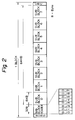
- Fig. 2 illustrates the structure of one block of a recording medium embodying the present invention.
- One block consists of an address (ADRS), a subblock header (SUBBLOCK HEADER), eight subblocks (SUBBLOCK) 0 to 7 and an error detection code (CRC: Cyclic Redundancy Check).
- the address the foremost element of one block, indicates the position of that block.
- the subblock header following the address consists of 32 bytes and indicates the types of information signals of the subblocks.
- the subblock header is therefore divided into eight areas where device labels (DL0 to DL7) as identification data indicating the types of the information signals of the associated subblocks are to be respectively described.
- the eight subblocks 0 to 7 follow the subblock header in order.
- the error detection code is located at the end of the block.
- blocks each having such a structure are repeatedly located in the order of their addresses along a track, with a sync signal (not shown in Fig. 2) inserted between consecutive blocks.
- Each of the eight device labels defines a maximum of 256 types of devices with values of 00H to FFH (H indicates a hexadecimal notation).
- 00H to FFH may be previously determined as follows.
- RESERVED NULL represents that the device has no significant meaning and is used when a dummy is necessary in a video image, a sound, data, etc.; the system need not read data from the associated subblock, thus ensuring an efficient operation.
- SYSTEM stores a control program or the like which is used by the system.
- VIDEO is a video signal
- AUDIO an audio signal.
- DATA is graphic data or MIDI (Musical Instrument Digital Interface) data
- SCSI Serial Computer System Interface
- CH1 to CH4 indicate channel numbers
- Fig. 3 illustrates a system for reproducing recorded information from a disk on which a digital information signal is recorded in the above-described format.
- a disk player 1 as reading means plays a disk 2 to output a digital reproduced signal.
- the disk 2 is placed on a turn table 4 by a loading mechanism 3 and is rotated by a spindle motor 5.
- the recorded information signal on the disk 2 is read out by an optical pickup 6.
- the pickup 6 is mounted on a slider (not shown) which moves in the radial direction of the disk 2 when driven by a slider motor 7 as a drive source.
- the output signal of the pickup 6 is an EFM (Eight to Fourteen Modulation) signal, for example, and this picked-up EFM signal is sent via an RF amplifier 8 to an EFM demodulator 9 where it is subjected to EFM demodulation.
- the resultant signal is then supplied to a subcode decoder 10 as well as to an error correcting circuit 11 for error correction.
- the subcode decoder 10 decodes subcode information such as the absolute time in the disk and frame number, and the decoded data is supplied to a player controller 13.
- the player controller 13 which is constituted of a microcomputer, performs positional control of the pickup 6 in the radial direction of the disk by driving the slider motor 7 via a slider driver 14, and control of the driving of the spindle motor 5 via a spindle driver 15, both under the control of the processor incorporated in the microcomputer. It is to be noted that a demodulating system other than the EFM may be used.
- the output of the error correcting circuit 11 is connected to a subblock header identifying circuit 17.
- This circuit 17 identifies the contents of the individual device labels (DL0-DL7) in the subheader using, for example, a table and distributes the subblocks at the timing according to the sync signal for each block of the digital reproduced signal output from the error correcting circuit 11.
- the subblock header identifying circuit 17 has distribution output terminals, which include audio outputs A1-A4, video outputs V1-V4, data outputs D1-D4 and SCSI outputs S1-S4.
- the audio outputs A1-A4 are connected to a 4-channel audio decoder 21, the video output V1 to a video decoder 22, the data output D1 to a MIDI decoder 23, and the SCSI output S1 to a SCSI decoder 24, as shown in Fig. 3.
- the audio decoder 21 converts a digital audio signal into an analog audio signal for each channel and supplies it to an amplifier (not shown).
- the video decoder 22 converts a digital video signal into an analog video signal and supplies it to a display device (not shown).
- the MIDI decoder 23 converts digital data into data conforming to the MIDI standards, and supplies the data to a MIDI machine (not shown).
- the SCSI decoder 24 serves as an interface with a microcomputer 25.
- the digital signal in the subblock 0 is supplied as a digital audio signal of the second channel to the audio decoder 21 from the audio output A2.
- the digital signal in the subblock 2 is supplied as a digital video signal of the first channel to the video decoder 22 from the video output V1.
- the digital signal in the subblock 3 is supplied as a digital video signal of the first channel to the video decoder 22 also from the video output V1.
- the digital signal in the subblock 4 is supplied to the MIDI decoder 23 from the data output D1.
- the digital signal in the subblock 5 is supplied to the SCSI decoder 24 from the SCSI output S1.
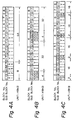
- the digital reproduced signal is output at the rate of nine blocks per sec or 72 subblocks per sec. If one block is assigned to a 4-channel audio signal and eight blocks are assigned to a 1-channel video signal on this optical disk, the transfer rate of the audio signal becomes 0.5 Mbps (4 x 128 Kbps) and the transfer rate of the video signal becomes 4.2 Mbps.
- Fig. 4 exemplifies the arrangements of the individual audio signals and video signals of the subblocks in this case.
- the arrangement of Fig. 4A is the format in which a 4-channel audio signal is assigned to one block with two subblocks provided per channel, and video signals are assigned to the subsequent eight blocks. In this case, nine blocks consisting of audio and video signals are repeated every second (30 frames).
- the arrangement of Fig. 4B is the format which allows a group of information signals including audio and video signals to be repeated in half the subblocks involved in the arrangement of Fig. 4A and in which a 4-channel audio signal is assigned to four subblocks in one block with one subblock provided per channel, and video signals are assigned to the subsequent four subblocks in that block and to the subsequent four blocks.
- This format corresponds one to one to the GOP (Group of Picture) structure of MPEG (Moving Picture Expert Group) and is advantageous for random access.
- the arrangement of Fig. 4C is designed to allow a group of information signals including audio and video signals to be repeated in half the subblocks involved in the arrangement of Fig. 4B.
- information signals such as audio and video signals
- information signals such as a system program, character information and MIDI data
- computer data D1 may be recorded together with a 4-channel audio signal and a 1-channel video signal as shown in Fig. 5.
- subblock header identifying circuit 17 is provided with distribution output terminals for four channels, namely the audio outputs A1-A4, video outputs V1-V4, data outputs D1-D4 and SCSI outputs S1-S4, in the above-described embodiment, the number of channels is not limited to four and the circuit 17 may be designed to handle more channels.
- the recording medium has been described as a disk in the foregoing description, it is in no way limited to this particular type, but the present invention may be adapted for other types of recording media such as a tape and a card.
- a plurality of subblocks in each of which a digital information signal is to be recorded are formed in each block, and the types of digital information signals for the associated subblocks are respectively recorded in a plurality of identification data blocks located preceding to the subblocks in one block and respectively associated with the subblocks, so that different types of digital information signals can be recorded in one block.
- the amount of one type of digital information in one block at a given time-dependent position is small and all the subblocks thus need not be used, other types of digital information signals can be recorded in the remaining subblocks, thus improving the use efficiency of the recording medium.
- the recorded information reproducing system embodying the present invention individual pieces of identification data in the subblock header are discriminated from the digital information signal output from the player, block by block, and the digital information signal is distributed to one of a plurality of decoders subblock by subblock in accordance with the identification data. Even if the recording medium in use has different types of digital information signals recorded in one block, the recorded digital information signals can properly be converted into the original information signals.
Abstract
Description
- The present invention relates to a recording medium on which multifarious types of digital information signals, such as audio data, video image data and computer data, are to be recorded, and a system for playing this recording medium to reproduce the recorded information.
- Disks, such as CD (Compact Disk), CD-ROM and CD-I (Compact Disk-Interactive), are known as recording media for storage of digital information signals. CD, as is well known, is a recording medium on which audio signals are recorded as main information, while CD-ROM is a recording medium on which digital information signals which a computer handles are recorded on the audio signal recording area on a CD and which is used for storage of read-only computer data. Both CD and CD-ROM can construct a large-capacity memory system of 600 MB (megabytes) at a maximum.
- A CD-I system is designed on the basis of this CD-ROM system and can interactively handle various types of digital information signals including audio data and video image data, such as a still picture, as well as computer data in accordance with applications. The CD-I system is designed for home use and educational purposes, and has specifications or the like for the range of what can be recorded on a disk and encoding determined in order to provide compatibility with various types of information. The aforementioned CD-I is a disk designed along this line.
- The data structure of the CD-I is specified in a standards book called the "green book", and is formed with information recording units called "blocks", as is the case for CD and CD-ROM. One block is equivalent to a time length of 1/75 second, and consists of 2352 bytes. The structure of one block will now be explained briefly. As shown in Fig. 1, four bytes following the first sync signal are a header where address information is recorded. Following the header is an 8-byte subheader where attribute data necessary to effect block-by-block time division of individual blocks in each of which only a single type of information signal, such as audio, video or computer data, is recorded, and to perform the processing in real time, is written twice. The attribute data consists of four items: the file number, channel number, submode and data type. Next to the subheader comes user data where a digital information signal is written. The user data consists of 2048 bytes in
form 1, and 2324 bytes inform 2. Whether that block is inform 1 orform 2 is specified by a flag in the submode in the subheader. Inform 1, a 4-byte error detection code (EDC) and a 276-byte error correction code (ECC) follows the user data. Inform 2, a 4-byte reserve data comes after the user data. - On a conventional recording medium such as the above-described CD-I, however, blocks are recorded in a time-division multiplex manner, each block containing a single type of information signal. In other words, only that information signal whose type is recorded in an area indicating the type of information signal in one block, like the data type item of the subheader of a CD-I, occupies that block. If the amount of information of a to-be-recorded information signal at a time-dependent position varies at random, therefore, the assigned block may not be filled with a single type of a digital information signal. In such a case, the remaining area in that block should be filled with dummy data and another type of a digital information signal cannot be recorded there, lowering the use efficiency of the recording medium.
- It is therefore an object of the present invention to provide a recording medium which can allow different types of digital information signals to be recorded in one block to thereby improve the recording efficiency, and a system for reproducing recorded information from the same.
- According to the present invention, there is provided a recording medium on which a digital information signal is to be recorded in the form of blocks, each block comprising an information portion consisting of a plurality of subblocks, and a header portion including a plurality of identification data blocks located preceding the information portion and respectively associated with the subblocks.
- Therefore, in the recording medium embodying the present invention, a plurality of subblocks in each of which a digital information signal is to be recorded are formed in each block, and the types of digital information signals for the associated subblocks are respectively recorded in a plurality of identification data blocks located preceding the subblocks in each block and respectively associated with the subblocks.
- According to another aspect of the present invention, there is further provided a recorded information reproducing system for a recording medium on which a digital information signal is to be recorded in the form of blocks, each block comprising an information portion consisting of a plurality of subblocks, and a header portion including a plurality of identification data blocks located preceding the information portion and respectively associated with the subblocks, the system comprising reading means for reading the digital information signal from the recording medium, a plurality of decoders for converting the digital information signal into an original information signal in accordance with a conversion mode corresponding to the type of the digital information signal, and identifying and distributing means for acquiring, block by block, identification data in the header portion from the digital information signal output from the reading means and distributing the digital information signal to one of the plurality of decoders subblock by subblock in accordance with the identification data.
- Therefore, in the recorded information reproducing system embodying the present invention, individual pieces of identification data in the header portion are discriminated from the digital information signal, read out from a recording medium by the reading means and output therefrom, block by block, and the digital information signal is distributed to one of a plurality of decoders subblock by subblock in accordance with the identification data to be converted into the original information signal.
- A number of preferred embodiments of the present invention will now be described by way of example only, and with reference to the accompanying drawings, in which:
- Fig. 1 is a diagram illustrating the physical format of one block of a CD-I;
- Fig. 2 is a diagram showing the physical format of one block of a recording medium according to the present invention;
- Fig. 3 is a block diagram illustrating the structure of a recorded information reproducing system according to the present invention; and
- Figs. 4 and 5 are diagrams exemplifying the arrangement of subblocks of different types of information signals.
- Fig. 2 illustrates the structure of one block of a recording medium embodying the present invention. One block consists of an address (ADRS), a subblock header (SUBBLOCK HEADER), eight subblocks (SUBBLOCK) 0 to 7 and an error detection code (CRC: Cyclic Redundancy Check). The address, the foremost element of one block, indicates the position of that block. The subblock header following the address consists of 32 bytes and indicates the types of information signals of the subblocks. The subblock header is therefore divided into eight areas where device labels (DL0 to DL7) as identification data indicating the types of the information signals of the associated subblocks are to be respectively described. The eight subblocks 0 to 7 follow the subblock header in order. The error detection code is located at the end of the block.
- On the recording medium, blocks each having such a structure are repeatedly located in the order of their addresses along a track, with a sync signal (not shown in Fig. 2) inserted between consecutive blocks.
- Given that the capacity of one subblock is 8 Kbytes, the total capacity of the eight
subblocks 0 to 7 becomes 64 Kbytes, as shown in Fig. 2. - Each of the eight device labels (DL0 to DL7) defines a maximum of 256 types of devices with values of 00H to FFH (H indicates a hexadecimal notation). 00H to FFH may be previously determined as follows.
00H: NULL 01H: SYSTEM 02H-0FH: RESERVED 10H-13H: VIDEO CH1-CH4 14H-1FH: RESERVED 20H-23H: AUDIO CH1-CH4 24H-2FH: RESERVED 30H-33H: DATA CH1-CH4 34H-3FH: RESERVED 40H-43H: SCSI CH1-CH4 44H-4FH: RESERVED
NULL represents that the device has no significant meaning and is used when a dummy is necessary in a video image, a sound, data, etc.; the system need not read data from the associated subblock, thus ensuring an efficient operation. SYSTEM stores a control program or the like which is used by the system. VIDEO is a video signal, and AUDIO an audio signal. DATA is graphic data or MIDI (Musical Instrument Digital Interface) data, and SCSI (Small Computer System Interface) is an interface signal between a computer and a peripheral device. CH1 to CH4 indicate channel numbers, and RESERVED indicates that the associated subblock is reserved for an information signal which will be set in the future. If the device label DL0 is set as DL0: DEVICE LABEL = 10H, the information signal in thesubblock 0 is a video signal of the first channel. With DL1: DEVICE LABEL = 21H, the information signal in thesubblock 1 is an audio signal of the second channel. - Fig. 3 illustrates a system for reproducing recorded information from a disk on which a digital information signal is recorded in the above-described format. In this recorded information reproducing system, a
disk player 1 as reading means plays adisk 2 to output a digital reproduced signal. In thisdisk player 1, thedisk 2 is placed on a turn table 4 by aloading mechanism 3 and is rotated by aspindle motor 5. The recorded information signal on thedisk 2 is read out by anoptical pickup 6. Thepickup 6 is mounted on a slider (not shown) which moves in the radial direction of thedisk 2 when driven by aslider motor 7 as a drive source. - The output signal of the
pickup 6 is an EFM (Eight to Fourteen Modulation) signal, for example, and this picked-up EFM signal is sent via anRF amplifier 8 to anEFM demodulator 9 where it is subjected to EFM demodulation. The resultant signal is then supplied to asubcode decoder 10 as well as to anerror correcting circuit 11 for error correction. Thesubcode decoder 10 decodes subcode information such as the absolute time in the disk and frame number, and the decoded data is supplied to aplayer controller 13. Theplayer controller 13, which is constituted of a microcomputer, performs positional control of thepickup 6 in the radial direction of the disk by driving theslider motor 7 via aslider driver 14, and control of the driving of thespindle motor 5 via aspindle driver 15, both under the control of the processor incorporated in the microcomputer. It is to be noted that a demodulating system other than the EFM may be used. - The output of the
error correcting circuit 11 is connected to a subblockheader identifying circuit 17. Thiscircuit 17 identifies the contents of the individual device labels (DL0-DL7) in the subheader using, for example, a table and distributes the subblocks at the timing according to the sync signal for each block of the digital reproduced signal output from theerror correcting circuit 11. The subblockheader identifying circuit 17 has distribution output terminals, which include audio outputs A1-A4, video outputs V1-V4, data outputs D1-D4 and SCSI outputs S1-S4. For instance, the audio outputs A1-A4 are connected to a 4-channel audio decoder 21, the video output V1 to avideo decoder 22, the data output D1 to aMIDI decoder 23, and the SCSI output S1 to aSCSI decoder 24, as shown in Fig. 3. Theaudio decoder 21 converts a digital audio signal into an analog audio signal for each channel and supplies it to an amplifier (not shown). Thevideo decoder 22 converts a digital video signal into an analog video signal and supplies it to a display device (not shown). TheMIDI decoder 23 converts digital data into data conforming to the MIDI standards, and supplies the data to a MIDI machine (not shown). TheSCSI decoder 24 serves as an interface with amicrocomputer 25. - When the subblock
header identifying circuit 17 identifies the digital reproduced signal from theerror correcting circuit 11 and when the content of the identified device label is DL0: DEVICE LABEL = 20H, the digital signal in thesubblock 0 is supplied as a digital audio signal of the first channel to theaudio decoder 21 from the audio output A1. When the content of the identified device label is DL1: DEVICE LABEL = 21H, the digital signal in thesubblock 0 is supplied as a digital audio signal of the second channel to theaudio decoder 21 from the audio output A2. If the normal mode is the case where the audio signal of the first channel is the audio signal of the left channel and the audio signal of the second channel is the audio signal of the right channel, the right and left channels are reversed by supplying DL0: DEVICE LABEL = 20H to the second channel and DL1: DEVICE LABEL = 21H to the first channel on the reproducing system side. If DL0: DEVICE LABEL = 20H and DL1: DEVICE LABEL = 20H, the audio signals of both right and left channels are supplied to the first channel input of theaudio decoder 21, providing a monoral mode. - When the content of the identified device label is DL2: DEVICE LABEL = 10H, the digital signal in the
subblock 2 is supplied as a digital video signal of the first channel to thevideo decoder 22 from the video output V1. When the content of the identified device label is DL3: DEVICE LABEL = 10H, the digital signal in thesubblock 3 is supplied as a digital video signal of the first channel to thevideo decoder 22 also from the video output V1. - When the content of the identified device label is DL4: DEVICE LABEL = 30H, the digital signal in the
subblock 4 is supplied to theMIDI decoder 23 from the data output D1. With DL5: DEVICE LABEL = 40H, the digital signal in thesubblock 5 is supplied to theSCSI decoder 24 from the SCSI output S1. As a result, with the video image data of DL2 treated as the main channel and the video image data of DL3 as the subchannel, it is possible to carry out imposition, such as superimposed dialogues, mixture of images, partial image replacing, masking, etc. by setting DL3 on and off on the reproducing system side. - When an optical disk which can be played at the transfer rate of 4.7 Mbps is used as a recording medium, the digital reproduced signal is output at the rate of nine blocks per sec or 72 subblocks per sec. If one block is assigned to a 4-channel audio signal and eight blocks are assigned to a 1-channel video signal on this optical disk, the transfer rate of the audio signal becomes 0.5 Mbps (4 x 128 Kbps) and the transfer rate of the video signal becomes 4.2 Mbps. Fig. 4 exemplifies the arrangements of the individual audio signals and video signals of the subblocks in this case.
- The arrangement of Fig. 4A is the format in which a 4-channel audio signal is assigned to one block with two subblocks provided per channel, and video signals are assigned to the subsequent eight blocks. In this case, nine blocks consisting of audio and video signals are repeated every second (30 frames). The arrangement of Fig. 4B is the format which allows a group of information signals including audio and video signals to be repeated in half the subblocks involved in the arrangement of Fig. 4A and in which a 4-channel audio signal is assigned to four subblocks in one block with one subblock provided per channel, and video signals are assigned to the subsequent four subblocks in that block and to the subsequent four blocks. This format corresponds one to one to the GOP (Group of Picture) structure of MPEG (Moving Picture Expert Group) and is advantageous for random access. The arrangement of Fig. 4C is designed to allow a group of information signals including audio and video signals to be repeated in half the subblocks involved in the arrangement of Fig. 4B.
- Further, besides digital information signals such as audio and video signals, information signals, such as a system program, character information and MIDI data, can be recorded on the recording medium. For instance, computer data D1 may be recorded together with a 4-channel audio signal and a 1-channel video signal as shown in Fig. 5.
- Although the subblock
header identifying circuit 17 is provided with distribution output terminals for four channels, namely the audio outputs A1-A4, video outputs V1-V4, data outputs D1-D4 and SCSI outputs S1-S4, in the above-described embodiment, the number of channels is not limited to four and thecircuit 17 may be designed to handle more channels. - Further, although the recording medium has been described as a disk in the foregoing description, it is in no way limited to this particular type, but the present invention may be adapted for other types of recording media such as a tape and a card.
- In short, according to the recording medium embodying the present invention, a plurality of subblocks in each of which a digital information signal is to be recorded are formed in each block, and the types of digital information signals for the associated subblocks are respectively recorded in a plurality of identification data blocks located preceding to the subblocks in one block and respectively associated with the subblocks, so that different types of digital information signals can be recorded in one block. In the case where the amount of one type of digital information in one block at a given time-dependent position is small and all the subblocks thus need not be used, other types of digital information signals can be recorded in the remaining subblocks, thus improving the use efficiency of the recording medium.
- According to the recorded information reproducing system embodying the present invention, individual pieces of identification data in the subblock header are discriminated from the digital information signal output from the player, block by block, and the digital information signal is distributed to one of a plurality of decoders subblock by subblock in accordance with the identification data. Even if the recording medium in use has different types of digital information signals recorded in one block, the recorded digital information signals can properly be converted into the original information signals.
Claims (2)
- A recording medium (2) on which a digital information signal is recorded in the form of blocks, each block comprising an information portion consisting of a plurality of subblocks, and a header portion including a plurality of identification data blocks located preceding said information portion and respectively associated with said subblocks.
- A recorded information reproducing system for a recording medium (2) on which a digital information signal is to be recorded in the form of blocks, each block comprising an information portion consisting of a plurality of subblocks, and a header portion including a plurality of identification data blocks located preceding the information portion and respectively associated with said subblocks, the system comprising:
reading means (6) for reading said digital information signal from said recording medium;
a plurality of decoders (21, 22, 23, 24) for converting said digital information signal into an original information signal in accordance with a conversion mode corresponding to the type of said digital information signal; and
identifying and distributing means (8, 9, 10, 11) for acquiring, block by block, identification data in said header portion from said digital information signal output from said reading means and distributing said digital information signal to one of said plurality of decoders subblock by subblock in accordance with the acquired identification data.
Applications Claiming Priority (2)
| Application Number | Priority Date | Filing Date | Title |
|---|---|---|---|
| JP45723/92 | 1992-03-03 | ||
| JP4572392A JPH05250809A (en) | 1992-03-03 | 1992-03-03 | Recording medium and system for reproducing its recorded information |
Publications (3)
| Publication Number | Publication Date |
|---|---|
| EP0558848A2 true EP0558848A2 (en) | 1993-09-08 |
| EP0558848A3 EP0558848A3 (en) | 1994-07-27 |
| EP0558848B1 EP0558848B1 (en) | 1997-12-10 |
Family
ID=12727262
Family Applications (1)
| Application Number | Title | Priority Date | Filing Date |
|---|---|---|---|
| EP19920308130 Expired - Lifetime EP0558848B1 (en) | 1992-03-03 | 1992-09-08 | Recording medium and system for reproducing recorded information therefrom |
Country Status (3)
| Country | Link |
|---|---|
| EP (1) | EP0558848B1 (en) |
| JP (1) | JPH05250809A (en) |
| DE (1) | DE69223498T2 (en) |
Cited By (10)
| Publication number | Priority date | Publication date | Assignee | Title |
|---|---|---|---|---|
| EP0644692A2 (en) * | 1993-09-16 | 1995-03-22 | Kabushiki Kaisha Toshiba | Video signals compression/decompression device for video disk recording/reproducing apparatus |
| EP0675493A2 (en) * | 1994-03-28 | 1995-10-04 | Kabushiki Kaisha Toshiba | Method of recording/reproducing optical disk by sector link data including address information of unit data or a program related to sectors, disk including the sector link data, and apparatus for and method of reproducing the disk |
| EP0676758A1 (en) * | 1994-04-08 | 1995-10-11 | Kabushiki Kaisha Toshiba | Method and apparatus for forming unit from image data, sound data, and header data divided at predetermined positions therein, and method, apparatus, and recording medium for reproducing unit |
| EP0726012A1 (en) * | 1993-10-29 | 1996-08-14 | Time Warner Entertainment Co., L.P. | An audio and video disc reproducing apparatus |
| EP0727074A1 (en) * | 1993-10-29 | 1996-08-21 | Time Warner Entertainment Co., L.P. | Data block format for software carrier and player therefor |
| BE1008964A3 (en) * | 1994-11-18 | 1996-10-01 | Philips Electronics Nv | Method for transfer of information, an information carrier, and a device for receiving and a device for sending information. |
| EP0836190A2 (en) * | 1993-10-29 | 1998-04-15 | Kabushiki Kaisha Toshiba | Information recording disk medium and reproduction apparatus |
| US5758007A (en) * | 1995-02-03 | 1998-05-26 | Kabushiki Kaisha Toshiba | Image information encoding/decoding system |
| WO2000072322A1 (en) * | 1999-05-20 | 2000-11-30 | Hitachi Maxell Limited | Removable memory and removable memory drive |
| CN1294567C (en) * | 1994-03-19 | 2007-01-10 | 索尼公司 | Optical disk, recording and fetch information method on disk and used device |
Families Citing this family (2)
| Publication number | Priority date | Publication date | Assignee | Title |
|---|---|---|---|---|
| KR100379573B1 (en) * | 2001-02-27 | 2003-04-10 | 주식회사 한단정보통신 | A file system for recording and displaying a digital broadcasting data |
| KR100912840B1 (en) * | 2007-11-14 | 2009-08-18 | 주식회사 한단정보통신 | An apparatus for storing digital broadcasting data in a set-top box and a method thereof |
Citations (3)
| Publication number | Priority date | Publication date | Assignee | Title |
|---|---|---|---|---|
| US4001883A (en) * | 1974-03-07 | 1977-01-04 | Honeywell Information Systems, Inc. | High density data storage on magnetic disk |
| WO1991018345A1 (en) * | 1990-05-22 | 1991-11-28 | Optical Media International | Voice message decoding and buffering system |
| EP0465246A2 (en) * | 1990-07-06 | 1992-01-08 | Pioneer Electronic Corporation | Information storage medium and apparatus for reproducing information therefrom |
-
1992
- 1992-03-03 JP JP4572392A patent/JPH05250809A/en active Pending
- 1992-09-08 DE DE1992623498 patent/DE69223498T2/en not_active Expired - Fee Related
- 1992-09-08 EP EP19920308130 patent/EP0558848B1/en not_active Expired - Lifetime
Patent Citations (3)
| Publication number | Priority date | Publication date | Assignee | Title |
|---|---|---|---|---|
| US4001883A (en) * | 1974-03-07 | 1977-01-04 | Honeywell Information Systems, Inc. | High density data storage on magnetic disk |
| WO1991018345A1 (en) * | 1990-05-22 | 1991-11-28 | Optical Media International | Voice message decoding and buffering system |
| EP0465246A2 (en) * | 1990-07-06 | 1992-01-08 | Pioneer Electronic Corporation | Information storage medium and apparatus for reproducing information therefrom |
Cited By (22)
| Publication number | Priority date | Publication date | Assignee | Title |
|---|---|---|---|---|
| EP0644692A3 (en) * | 1993-09-16 | 1996-07-03 | Toshiba Kk | Video signals compression/decompression device for video disk recording/reproducing apparatus. |
| EP0644692A2 (en) * | 1993-09-16 | 1995-03-22 | Kabushiki Kaisha Toshiba | Video signals compression/decompression device for video disk recording/reproducing apparatus |
| US5715356A (en) * | 1993-09-16 | 1998-02-03 | Kabushiki Kaisha Toshiba | Apparatus for processing compressed video signals which are be recorded on a disk or which have been reproduced from a disk |
| EP0836190A2 (en) * | 1993-10-29 | 1998-04-15 | Kabushiki Kaisha Toshiba | Information recording disk medium and reproduction apparatus |
| EP0969464A1 (en) * | 1993-10-29 | 2000-01-05 | Time Warner Entertainment Co., L.P. | Data block format for software carrier and player therfor |
| EP0727074A1 (en) * | 1993-10-29 | 1996-08-21 | Time Warner Entertainment Co., L.P. | Data block format for software carrier and player therefor |
| EP0969472A1 (en) * | 1993-10-29 | 2000-01-05 | Time Warner Entertainment Co., L.P. | Data block format for software carrier and player therefor |
| EP0726012A1 (en) * | 1993-10-29 | 1996-08-14 | Time Warner Entertainment Co., L.P. | An audio and video disc reproducing apparatus |
| EP0727074A4 (en) * | 1993-10-29 | 1998-10-07 | Time Warner Entertainm Co Lp | Data block format for software carrier and player therefor |
| EP0726012A4 (en) * | 1993-10-29 | 1998-04-29 | Time Warner Entertainm Co Lp | An audio and video disc reproducing apparatus |
| EP0836190A3 (en) * | 1993-10-29 | 1998-04-22 | Kabushiki Kaisha Toshiba | Information recording disk medium and reproduction apparatus |
| CN1294567C (en) * | 1994-03-19 | 2007-01-10 | 索尼公司 | Optical disk, recording and fetch information method on disk and used device |
| EP0675493A2 (en) * | 1994-03-28 | 1995-10-04 | Kabushiki Kaisha Toshiba | Method of recording/reproducing optical disk by sector link data including address information of unit data or a program related to sectors, disk including the sector link data, and apparatus for and method of reproducing the disk |
| EP0675493A3 (en) * | 1994-03-28 | 1997-11-19 | Kabushiki Kaisha Toshiba | Method of recording/reproducing optical disk by sector link data including address information of unit data or a program related to sectors, disk including the sector link data, and apparatus for and method of reproducing the disk |
| US5946447A (en) * | 1994-03-28 | 1999-08-31 | Kabushiki Kaisha Toshiba | Apparatus and method for recording/retrieving data on/from a disk having data stored thereon in a logical hierarchy |
| EP0676758A1 (en) * | 1994-04-08 | 1995-10-11 | Kabushiki Kaisha Toshiba | Method and apparatus for forming unit from image data, sound data, and header data divided at predetermined positions therein, and method, apparatus, and recording medium for reproducing unit |
| US5684768A (en) * | 1994-04-08 | 1997-11-04 | Kabushiki Kaisha Toshiba | Method and apparatus for forming unit from image data, sound data, and header data divided at predetermined positions therein, and method, apparatus, and recordig medium for reproducing unit |
| BE1008964A3 (en) * | 1994-11-18 | 1996-10-01 | Philips Electronics Nv | Method for transfer of information, an information carrier, and a device for receiving and a device for sending information. |
| US5758007A (en) * | 1995-02-03 | 1998-05-26 | Kabushiki Kaisha Toshiba | Image information encoding/decoding system |
| US6031963A (en) * | 1995-02-03 | 2000-02-29 | Kabushiki Kaisha Toshiba | Image information encoding/decoding system |
| US6253025B1 (en) | 1995-02-03 | 2001-06-26 | Kabushiki Kaisha Toshiba | Image information encoding/decoding system |
| WO2000072322A1 (en) * | 1999-05-20 | 2000-11-30 | Hitachi Maxell Limited | Removable memory and removable memory drive |
Also Published As
| Publication number | Publication date |
|---|---|
| EP0558848A3 (en) | 1994-07-27 |
| DE69223498T2 (en) | 1998-05-07 |
| DE69223498D1 (en) | 1998-01-22 |
| EP0558848B1 (en) | 1997-12-10 |
| JPH05250809A (en) | 1993-09-28 |
Similar Documents
| Publication | Publication Date | Title |
|---|---|---|
| US5461371A (en) | Exhibit explaining system activated by infrared signals | |
| AU709193B2 (en) | Recording medium, recording apparatus, reproducing method, and reproducing apparatus | |
| USRE44729E1 (en) | Apparatus and method for processing audio signals recorded on a medium | |
| EP0165320A1 (en) | Disk-shaped recording medium and apparatus for reproducing the same | |
| EP0999552A3 (en) | Information recording medium and reproducing apparatus | |
| EP0558848B1 (en) | Recording medium and system for reproducing recorded information therefrom | |
| EP0795872A3 (en) | Information record medium, apparatus for recording the same and apparatus for reproducing the same | |
| CA2200538C (en) | Data arranging method and medium for data recording or transfer, and signal processing apparatus for the method and medium | |
| EP0390576A1 (en) | Recording/reproducing apparatus | |
| US5159143A (en) | Information recording medium player for controlling musical devices using a musical instrument digital interface (MIDI) format signal | |
| EP0883125A3 (en) | Digital versatile disc and reproduction apparatus using the same | |
| US7457531B2 (en) | Low bandwidth image system | |
| JP3517962B2 (en) | Disk recording and playback device | |
| JPH05210894A (en) | Device for obtaining tape-shaped magnetic recording carrier recorded, recording carrier obtained by such device and reproducer for reproducing recording carrier | |
| EP0624978B1 (en) | Apparatus for recording and playing back digital data | |
| KR970002862B1 (en) | Disk recording medium and its reproduction method and apparatus | |
| JPH02193317A (en) | Optical disk | |
| US6396784B1 (en) | Audio compact disc title with a relatively high density format | |
| JP3430489B2 (en) | Recording method of video tape recorder that records character information in index area | |
| KR100618986B1 (en) | Storage medium storing additional information for simultaneous reproduction, method and apparatus of recording/reproducing | |
| JPH02260258A (en) | Recording and reproducing device | |
| CN1182935A (en) | Electronic equipment | |
| JPH0332191A (en) | Recording and reproducing device | |
| JPH07235146A (en) | Recording apparatus | |
| JPH07110060B2 (en) | Recording / playback device |
Legal Events
| Date | Code | Title | Description |
|---|---|---|---|
| PUAI | Public reference made under article 153(3) epc to a published international application that has entered the european phase |
Free format text: ORIGINAL CODE: 0009012 |
|
| AK | Designated contracting states |
Kind code of ref document: A2 Designated state(s): DE FR GB |
|
| PUAL | Search report despatched |
Free format text: ORIGINAL CODE: 0009013 |
|
| AK | Designated contracting states |
Kind code of ref document: A3 Designated state(s): DE FR GB |
|
| 17P | Request for examination filed |
Effective date: 19941104 |
|
| 17Q | First examination report despatched |
Effective date: 19960820 |
|
| GRAG | Despatch of communication of intention to grant |
Free format text: ORIGINAL CODE: EPIDOS AGRA |
|
| GRAH | Despatch of communication of intention to grant a patent |
Free format text: ORIGINAL CODE: EPIDOS IGRA |
|
| GRAH | Despatch of communication of intention to grant a patent |
Free format text: ORIGINAL CODE: EPIDOS IGRA |
|
| GRAA | (expected) grant |
Free format text: ORIGINAL CODE: 0009210 |
|
| AK | Designated contracting states |
Kind code of ref document: B1 Designated state(s): DE FR GB |
|
| REF | Corresponds to: |
Ref document number: 69223498 Country of ref document: DE Date of ref document: 19980122 |
|
| ET | Fr: translation filed | ||
| REG | Reference to a national code |
Ref country code: GB Ref legal event code: 746 Effective date: 19980702 |
|
| REG | Reference to a national code |
Ref country code: FR Ref legal event code: D6 |
|
| PLBE | No opposition filed within time limit |
Free format text: ORIGINAL CODE: 0009261 |
|
| STAA | Information on the status of an ep patent application or granted ep patent |
Free format text: STATUS: NO OPPOSITION FILED WITHIN TIME LIMIT |
|
| 26N | No opposition filed | ||
| REG | Reference to a national code |
Ref country code: GB Ref legal event code: IF02 |
|
| REG | Reference to a national code |
Ref country code: FR Ref legal event code: TP |
|
| REG | Reference to a national code |
Ref country code: GB Ref legal event code: 732E |
|
| PGFP | Annual fee paid to national office [announced via postgrant information from national office to epo] |
Ref country code: FR Payment date: 20050823 Year of fee payment: 14 |
|
| PGFP | Annual fee paid to national office [announced via postgrant information from national office to epo] |
Ref country code: DE Payment date: 20050902 Year of fee payment: 14 |
|
| PGFP | Annual fee paid to national office [announced via postgrant information from national office to epo] |
Ref country code: GB Payment date: 20050907 Year of fee payment: 14 |
|
| PG25 | Lapsed in a contracting state [announced via postgrant information from national office to epo] |
Ref country code: DE Free format text: LAPSE BECAUSE OF NON-PAYMENT OF DUE FEES Effective date: 20070403 |
|
| GBPC | Gb: european patent ceased through non-payment of renewal fee |
Effective date: 20060908 |
|
| REG | Reference to a national code |
Ref country code: FR Ref legal event code: ST Effective date: 20070531 |
|
| PG25 | Lapsed in a contracting state [announced via postgrant information from national office to epo] |
Ref country code: GB Free format text: LAPSE BECAUSE OF NON-PAYMENT OF DUE FEES Effective date: 20060908 |
|
| PG25 | Lapsed in a contracting state [announced via postgrant information from national office to epo] |
Ref country code: FR Free format text: LAPSE BECAUSE OF NON-PAYMENT OF DUE FEES Effective date: 20061002 |