EP0561051A2 - Compact leak-resistant seal for thermal ink jet print cartridge ink reservoir - Google Patents
Compact leak-resistant seal for thermal ink jet print cartridge ink reservoir Download PDFInfo
- Publication number
- EP0561051A2 EP0561051A2 EP92120853A EP92120853A EP0561051A2 EP 0561051 A2 EP0561051 A2 EP 0561051A2 EP 92120853 A EP92120853 A EP 92120853A EP 92120853 A EP92120853 A EP 92120853A EP 0561051 A2 EP0561051 A2 EP 0561051A2
- Authority
- EP
- European Patent Office
- Prior art keywords
- shot
- mold
- standpipe
- leak
- standpipe member
- Prior art date
- Legal status (The legal status is an assumption and is not a legal conclusion. Google has not performed a legal analysis and makes no representation as to the accuracy of the status listed.)
- Granted
Links
Images


Classifications
-
- B—PERFORMING OPERATIONS; TRANSPORTING
- B41—PRINTING; LINING MACHINES; TYPEWRITERS; STAMPS
- B41J—TYPEWRITERS; SELECTIVE PRINTING MECHANISMS, i.e. MECHANISMS PRINTING OTHERWISE THAN FROM A FORME; CORRECTION OF TYPOGRAPHICAL ERRORS
- B41J2/00—Typewriters or selective printing mechanisms characterised by the printing or marking process for which they are designed
- B41J2/005—Typewriters or selective printing mechanisms characterised by the printing or marking process for which they are designed characterised by bringing liquid or particles selectively into contact with a printing material
- B41J2/01—Ink jet
- B41J2/17—Ink jet characterised by ink handling
- B41J2/175—Ink supply systems ; Circuit parts therefor
- B41J2/17503—Ink cartridges
- B41J2/17553—Outer structure
-
- B—PERFORMING OPERATIONS; TRANSPORTING
- B29—WORKING OF PLASTICS; WORKING OF SUBSTANCES IN A PLASTIC STATE IN GENERAL
- B29C—SHAPING OR JOINING OF PLASTICS; SHAPING OF MATERIAL IN A PLASTIC STATE, NOT OTHERWISE PROVIDED FOR; AFTER-TREATMENT OF THE SHAPED PRODUCTS, e.g. REPAIRING
- B29C45/00—Injection moulding, i.e. forcing the required volume of moulding material through a nozzle into a closed mould; Apparatus therefor
- B29C45/16—Making multilayered or multicoloured articles
- B29C45/1657—Making multilayered or multicoloured articles using means for adhering or bonding the layers or parts to each other
-
- B—PERFORMING OPERATIONS; TRANSPORTING
- B41—PRINTING; LINING MACHINES; TYPEWRITERS; STAMPS
- B41J—TYPEWRITERS; SELECTIVE PRINTING MECHANISMS, i.e. MECHANISMS PRINTING OTHERWISE THAN FROM A FORME; CORRECTION OF TYPOGRAPHICAL ERRORS
- B41J2/00—Typewriters or selective printing mechanisms characterised by the printing or marking process for which they are designed
- B41J2/005—Typewriters or selective printing mechanisms characterised by the printing or marking process for which they are designed characterised by bringing liquid or particles selectively into contact with a printing material
- B41J2/01—Ink jet
- B41J2/17—Ink jet characterised by ink handling
- B41J2/175—Ink supply systems ; Circuit parts therefor
- B41J2/17503—Ink cartridges
- B41J2/17506—Refilling of the cartridge
-
- B—PERFORMING OPERATIONS; TRANSPORTING
- B41—PRINTING; LINING MACHINES; TYPEWRITERS; STAMPS
- B41J—TYPEWRITERS; SELECTIVE PRINTING MECHANISMS, i.e. MECHANISMS PRINTING OTHERWISE THAN FROM A FORME; CORRECTION OF TYPOGRAPHICAL ERRORS
- B41J2/00—Typewriters or selective printing mechanisms characterised by the printing or marking process for which they are designed
- B41J2/005—Typewriters or selective printing mechanisms characterised by the printing or marking process for which they are designed characterised by bringing liquid or particles selectively into contact with a printing material
- B41J2/01—Ink jet
- B41J2/17—Ink jet characterised by ink handling
- B41J2/175—Ink supply systems ; Circuit parts therefor
- B41J2/17503—Ink cartridges
- B41J2/17513—Inner structure
-
- B—PERFORMING OPERATIONS; TRANSPORTING
- B41—PRINTING; LINING MACHINES; TYPEWRITERS; STAMPS
- B41J—TYPEWRITERS; SELECTIVE PRINTING MECHANISMS, i.e. MECHANISMS PRINTING OTHERWISE THAN FROM A FORME; CORRECTION OF TYPOGRAPHICAL ERRORS
- B41J2/00—Typewriters or selective printing mechanisms characterised by the printing or marking process for which they are designed
- B41J2/005—Typewriters or selective printing mechanisms characterised by the printing or marking process for which they are designed characterised by bringing liquid or particles selectively into contact with a printing material
- B41J2/01—Ink jet
- B41J2/17—Ink jet characterised by ink handling
- B41J2/175—Ink supply systems ; Circuit parts therefor
- B41J2/17503—Ink cartridges
- B41J2/1752—Mounting within the printer
- B41J2/17523—Ink connection
-
- B—PERFORMING OPERATIONS; TRANSPORTING
- B41—PRINTING; LINING MACHINES; TYPEWRITERS; STAMPS
- B41J—TYPEWRITERS; SELECTIVE PRINTING MECHANISMS, i.e. MECHANISMS PRINTING OTHERWISE THAN FROM A FORME; CORRECTION OF TYPOGRAPHICAL ERRORS
- B41J2/00—Typewriters or selective printing mechanisms characterised by the printing or marking process for which they are designed
- B41J2/005—Typewriters or selective printing mechanisms characterised by the printing or marking process for which they are designed characterised by bringing liquid or particles selectively into contact with a printing material
- B41J2/01—Ink jet
- B41J2/17—Ink jet characterised by ink handling
- B41J2/175—Ink supply systems ; Circuit parts therefor
- B41J2/17503—Ink cartridges
- B41J2/17559—Cartridge manufacturing
-
- B—PERFORMING OPERATIONS; TRANSPORTING
- B29—WORKING OF PLASTICS; WORKING OF SUBSTANCES IN A PLASTIC STATE IN GENERAL
- B29C—SHAPING OR JOINING OF PLASTICS; SHAPING OF MATERIAL IN A PLASTIC STATE, NOT OTHERWISE PROVIDED FOR; AFTER-TREATMENT OF THE SHAPED PRODUCTS, e.g. REPAIRING
- B29C45/00—Injection moulding, i.e. forcing the required volume of moulding material through a nozzle into a closed mould; Apparatus therefor
- B29C45/16—Making multilayered or multicoloured articles
- B29C45/1657—Making multilayered or multicoloured articles using means for adhering or bonding the layers or parts to each other
- B29C2045/1665—Shrinkage bonds
Definitions
- This polyethylene "second shot” has a degree of mold shrinkage (such as, for high density polyethylene without glass, about 0.022 inches/inch); upon cooling, the polyethylene material shrinks tightly onto the ribs of the first shot.
- the necessary property of the second molded material is that it shrinks during the cooling process.
Abstract
Description
- This invention relates to ink reservoirs for thermal ink jet ("TIJ") print cartridges.
- TIJ technology is widely used in computer printers. Very generally, a TIJ includes a print head typically comprises several tiny controllable ink jets, which are selectively activated to release a jet or spray of ink from an ink reservoir onto the print media (such as paper) in order to create an image or portion of an image. TIJ printers are described, for example, in the Hewlett-Packard Journal,
Volume 36, Number 5, May, 1985, and Volume 39,Number 4, August, 1988. - In TIJ pens it is necessary to connect the ink reservoir to the print head. The size of this connection affects the design of the printer that the pens are used in. An ideal reservoir-to-print-head coupler, from a printer design point of view, would be no longer than the TIJ head is long, and would be high or tall enough to allow the drive and pinch wheels to get as close to the print head as possible. Any increase in the size of this coupler will compromise the paper handling ability, which may affect the print quality, and increase the size of the printer. Smaller printers are desirable as they conserve desk space and the materials from which the printer is fabricated.
- An intended application for this invention is for a spring bag TIJ pen, although it is not limited to the spring bag pen. In one exemplary spring bag pen design, the pen frame made of a first molded material is lined with a second molded material, such as polyethylene, on the inside to produce a surface suitable for staking the films of the spring bag. The first molded material from which the frame is made could be, for example, an engineering plastic, and provides the necessary structure for the pen which could not be accomplished with the second molded material. This invention relates to the fluid connection of the first and second molded materials in such a way as to provide a space-efficient, leak-resistant connection.
- Conventional methods of connecting materials include the use of glue, seals, such as gaskets or O-rings, or mechanical press fits. In these cases two or more separate parts are fabricated and assembled together to form a single unit. Each part must be designed and sized with respect to its needs in manufacturing, structural integrity, and with the tolerance of the mating part in mind. Such joints as these take up much more space than joints fabricated in accordance with this invention. In addition to taking up much space, the traditional methods produce a joint whose reliability can be affected by the part tolerances, surface finishes, and the assembly operation. The method of this invention provides a joint which is less susceptible to surface finish defects than joints obtained by such traditional methods.
- A thermal inkjet print cartridge ink reservoir in accordance with the invention is characterized by a compact, leak-resistant joint between first and second moldable materials which define the frame of the reservoir. The reservoir includes a first frame element having a snout end and defining an interior standpipe member through which a channel opening extends. The channel opening extends between the ink reservoir chamber and a thermal inkjet print head. The first frame element is fabricated from a first moldable plastic.
- The ink reservoir includes a second frame element fabricated from a second moldable plastic material characterized by a shrink rate as the material cools from a molten state. The second frame element is formed by injection molding and surrounds the periphery of the standpipe member to thereby provide the compact, leak-resistent joint, in that the second moldable material has shrunk about the periphery of the standpipe member to define the joint.
- A method in accordance with this invention is for forming a leak-resistant joint between first and second moldable materials, and includes the following steps:
molding the first material into a predetermined first shot structure defining an interior fluid standpipe through which a channel opening extends;
positioning the first shot structure in a second shot mold;
injecting the second moldable material in a molten state into the mold as a second shot wherein the second material surrounds the standpipe member, the second material characterized by a shrink rate as the material cools; and
permitting the second material to cool, whereupon the second material shrinks about the periphery of the standpipe, thereby forming a leak-resistant seal between the first and second materials about the standpipe. - Use of this method to join the two materials allows the surface of the first shot to be used, as molded, and the molding negates the effects of the tolerance and surface finish of the second molded material on the joint. When the second molded material is molded onto the first molded material it shrinks as it cools and produces a tight joint.
- This method of connection is more reliable than conventional methods. Since the second molded material, e.g., polyethylene, is molded onto the first molded material, which can be used as a structural element, the first molded material imparts stiffness to the second molded material. The second molded material therefore can be designed to be thinner in cross section than if the part were made by conventional methods. Because the second molded material is never handled as a separate part on an assembly line, as would be the case in a traditional two-part design, its cross sections are not burdened by the stiffness that handling would require, and therefore the design is more compact from this perspective also.
- These and other features and advantages of the present invention will become more apparent from the following detailed description of an exemplary embodiment thereof, as illustrated in the accompanying drawings, in which:
- FIG. 1 illustrates a thermal inkjet print cartridge ink reservoir embodying the present invention.
- FIG. 2 is a close-up view of the snout region of the rigid engineering plastic member comprising the ink reservoir of FIG. 1.
- FIG. 3 is a close-up view of the snout region of the ink reservoir of FIG. 1, showing both the rigid plastic member and the polyethylene member comprising the ink reservoir.
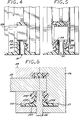
- FIG. 4 is a cross-sectional view taken along line 4-4 of FIG. 2.
- FIG. 5 is a cross-sectional view taken along line 5-5 of FIG. 3.
- FIG. 6 illustrates the second "shot" process in which the polyethylene member comprising the frame of the ink reservoir is molded.
- FIGS. 1-6 illustrates a compact thermal inkjet print
cartridge ink reservoir 20 in accordance with this invention. In this exemplary embodiment, the backbone or frame 22 of thereservoir 20 comprises two chemically dissimilar plastics, an engineering plastic, e.g., a glass-filled modified polyphenylene oxide (such as the material sold under the trademark "NORYL"), and 10 percent glass-filled polyethylene, which are molded one onto the other to form a leak-resistant joint in accordance with this invention. The frame 22 is stiffened by a pair of sheet metal covers 24 (only one of which is visible in FIG. 1) which attach to its sides. This structure of frame 22 andcovers 24 is intended for use with a spring bag ink delivery system of the type described in pending U.S. patent application serial number 07/717,735, filed June 19, 1991, entitled "Spring-Bag Printer Ink Cartridge with Volume Indicator," by David S. Hunt and W. Bruce Reid and assigned to a common assignee with the present invention. A print head (not shown) is connected at thesnout end 26 of the reservoir for selectively releasing a jet of ink from the reservoir. - In accordance with the invention, the seal between the two dissimilar materials comprising the frame 22 employs a shrink fit at the container snout end to clamp the two plastics tightly together. FIG. 2 illustrates the
snout end 26 of thereservoir 20 in its form prior to molding thepolyethylene 22B onto the engineeringplastic frame member 22A. Themember 22A is an integrally formed frame member molded of the engineering plastic. At thesnout end 26, themember 22A defines an interior,upright fluid standpipe 28 having aninterior opening 30 defined therein which extends through the standpipe to an opening formed in the exterior surface of theframe member 22A. It is through this opening that the ink will flow from the reservoir. The ink jet head (not shown) will be positioned along thesurface 36. - The
end 26 of themember 22A is shown in further detail in the cross-sectional view of FIG. 4. FIG. 2 illustrates theopen region 32 surrounding the upwardly extendingfluid standpipe 28 within theframe 22A. A pair of spacedribs standpipe 28. - Now referring to FIGS. 3 and 5, the reservoir frame 22 is shown with the
polyethylene layer 22B molded to the inside surface of theframe 22A. Thelayer 22B in theregion 26 is best illustrated in the cross-sectional view of FIG. 5. Thepolyethylene material 22B has been molded around the periphery of thestandpipe 28, without covering the opening 30. Thepolyethylene material 22B provides a surface to which the spring bag film may be staked. It is therefore important that there be no leaks between thestandpipe 28 and the surrounding molded layer of polyethylene, as this would defeat the integrity of the reservoir, and permit ink to leak from the reservoir, or air to get into the reservoir. - The method of molding the
layer 22B to theframe element 22A is now described. First, theframe element 22A of modified polyphenylene oxide, i.e., a first molded material, is fabricated in a plastic injection mold. Thispart 22A, referred to as the "first shot," is illustrated in FIGS. 2 and 4. Thefirst shot 22A is next inserted into a second mold, where thepolyethylene 22B, i.e., the second molded material, is molded onto it. The polyethylene is injected into the mold under appropriate pressure and at an appropriate temperature. For polyethylene, an exemplary pressure is in the range of 4,000 to 10,000 psi, and an exemplary melt temperature is 400° F. This polyethylene "second shot" has a degree of mold shrinkage (such as, for high density polyethylene without glass, about 0.022 inches/inch); upon cooling, the polyethylene material shrinks tightly onto the ribs of the first shot. Thus, the necessary property of the second molded material is that it shrinks during the cooling process. - FIG. 6 illustrates the second shot molding process. A cavity mold pin 50 is extended above the top of the
channel 30. The cavity mold pin 50 is attached to and moves with the mold half 54. A channel cavity mold pin 52 is inserted into thechannel opening 30 formed in theframe member 22A and against the cavity mold pin 50. The mold halves 54 and 56 are closed together, defining the interior opening into which the molten polyethylene is injected or "shot," together with surfaces of the first molded material. Thus, according to another aspect of the invention, the mold cavity for the second shot is partially defined by surfaces of the first shot, i.e., the first molded material. Surfaces of theframe member 22A serve as stop surfaces against which the respective mold halves bear when the mold is closed to stop the flow of the molten second material. Thus, in FIG. 6surfaces frame member 22A are contacted, or brought in close proximity, such as 0.001 inch or less, by corresponding surfaces of the mold halves 54 and 56, and prevent flow of the second material into the mold cavities generally indicated by 55 and 57. - After the second "shot" of polyethylene is cooled, forming the
polyethylene member 22B, the mold halves 54 and 56 are separated. The mold pin 52 is withdrawn during mold separation. - The molded joint resulting from this invention retains water and thermal inkjet printing inks, and keeps air out under moderate pressure and vacuum, through a range of environmental conditions normally experienced by office products. The internal stresses inherent to the second shot, as it shrinks about the standpipe, keep it from pulling away from the first shot. The mold and first shot material, which are at a lower temperature than the second shot molding temperature, cool the second shot material.
- When the polymer passes through its glass transition temperature, it changes phases from liquid to solid. When in the solid state the plastic temperature continues to drop from its glass transition temperature Tg to the mold temperature, e.g., where Tg is on the order of 300°F and the mold temperature is on the order of 100°F. The thermal contractions during this part of the cooling process results in the formation of internal stresses in the now solid second shot.
- The process of this invention is applicable to multi-cavity molding and also two-shot molding, where both plastics are injected during different cycles of the same molding machine. As is well known in the art, multi-cavity molds are used to produce as many parts per cycle as there are cavities in the mold.
- Pressure decay leak-testing of parts fabricated using this seal show minimal leak rates. Further, the seal has proven to endure throughout the print cartridge assembly process, during which the ink reservoir is subjected to mechanical and thermal stresses. The seal has been tested successfully with various ribs and different plastic materials, such as polysulfone for the first shot, i.e., the first molded material, and glass-filled polyethylene as the second shot, i.e., the second molded material. Other materials may be suitable for the first and second molded materials.
- The joint created by the method of the present invention is resistent to air leaks into the reservoir and ink leaks out of the reservoir, i.e., it is resistent to the leakage of air into the closed ink reservoir via the joint at the materials interface at the standpipe, and to the leakage of ink out of the interface via the joint. The joint is of value even if not air-tight, as it would be necessary for air to bubble through the interface formed by the materials of the first and second shots wetted by ink via a bubble generator effect. Air would bubble through the interface only under a pressure differential well above conditions likely to be faced by an ink jet cartridge.
- While the standpipe described above has two ribs, such ribs are not necessary for the joint to properly function as a leak-resistent joint. The ribs do add leak-resistent margin by making the capillary path that the ink must travel to leak out more tortuous, and therefor adds to the energy necessary for the ink to leak. However, some applications may not allow the use of such ribs, and the joint without ribs is still leak-resistent.
- While the preferred embodiment has employed dissimilar plastic materials as the first and second molded materials, that is not necessary to obtain a leak-resistent joint with the invention. In fact, in particular applications, the same material can be used for both materials, so long as the material is characterized by the property that it shrinks upon cooling from the liquid state to the solid state.
- The first shot material is typically characterized by a higher melting temperature than the second shot material. The first shot material could be compounded or non-compounded relative to the virgin base material. In this context a "compounded" material is one in which additives such as glass bead, glass fiber, talc, metal particles, or the like have been blended with the base material. For example, compounded materials suitable for use as the first shot material include 20% glass-filled modified polyphenylene oxide or glass-filled polysulfone. Polyethylene terephthalate (PET), either filled or non-filled, is also suitable for use as the first shot material.
- The second shot material preferably has a melting point which is equal to or less than the melting temperature of the first shot material, although in some applications, a second shot material with a higher melting temperature than the first shot could be used. The second shot material can be compounded or non-compounded material, such as glass-filled or non-glass-filled polypropylene, or the like, or even glass-filled or non-glass-filled polysulfone.
- An advantage gained from this invention is the ability to attach the two plastic parts without an intermediate assembly step. Each plastic material is specified for its unique properties in different aspects of print cartridge reservoir assembly and operation; previously such a combination had to be fabricated separately and then joined. Using this seal, no assembly equipment is required, only one part need be handled, and there is no yield loss associated with imperfect joints. The two plastic components are attached to each other without resorting to devices such as snap fits, screw holes, etc., which would take up additional space; instead, all of the space in the ink reservoir is utilized for attachment of the covers and the spring bag films, ensuring adequate stiffness and making effective use of the available space for storing ink.
- It is understood that the above-described embodiments are merely illustrative of the possible specific embodiments which may represent principles of the present invention. Other arrangements may readily be devised in accordance with these principles by those skilled in the art without departing from the scope and spirit of the invention.
Claims (10)
- A method for forming a leak-resistant joint between first and second moldable materials, characterized by a sequence of the following steps:
molding said first material into a predetermined first shot structure (22A) defining an interior standpipe member (28);
positioning said first shot structure (22A) in a second shot mold (54, 56);
injecting said second moldable material in a molten state into said mold as a second shot wherein said second material surrounds said standpipe member (28), said second material characterized by a shrink rate as said material cools;
permitting said second material to cool, whereupon said second material (22B) shrinks about the periphery of said standpipe member, thereby forming a leak-resistant seal between said first and second materials about said standpipe member. - A method according to Claim 1 wherein said first shot structure is characterized by one or more protruding peripheral ribs (34, 35) extending outwardly from said standpipe member, wherein said second material (22B) is molded about said one or more ribs.
- A method according to Claim 1 or Claim 2, further characterized in that said mold comprises first and second mold halves (54, 56) which can be closed about said first shot structure (22A) and serves in the definition of one or more mold cavities into which said second material is injected under pressure, and which can be opened upon adequate cooling to permit removal of said molded structure therefrom.
- A method according to Claim 3 further characterized in that a portion of said first shot structure also serves in the definition of said one or more mold cavities.
- A method according to any preceding claim, wherein said interior standpipe (28) is further characterized by a channel opening (30) extending therethrough, and said mold comprises a channel mold pin (52) for extending through said channel opening to prevent said second material from entering said channel opening during said second shot.
- A method according to Claim 5 further characterized in that said mold further comprises a cavity mold pin (50) which extends across said channel opening (30), said channel mold pin (52) stopping against said cavity mold pin (50).
- A method according to any preceding claim, further characterized in that said first material is selected from the group comprising polyphenylene oxide, polysulfone and polyethylene terephthalate.
- A method according to any preceding claim, further characterized in that said second material is selected from the group comprising polyethylene, polyprophylene and polysulfone.
- A thermal inkjet printer cartridge including a thermal inkjet printhead and an ink reservoir, the cartridge characterized by a compact, leak-resistant joint between first and second moldable materials which define in part said ink reservoir, comprising:
a first frame element (22A) having a snout end (26) and defining an interior standpipe member (28) through which a channel opening (30) extends, said channel opening (30) extending between said ink reservoir and a thermal inkjet print head, said first frame element (22A) fabricated from a first moldable plastic; and
a second frame element (22B) fabricated from a second moldable plastic material characterized by a shrinkage rate as said material cools, said second frame element being formed by injection molding and surrounding the periphery of said standpipe member (28) to thereby provide said joint, said second moldable material having been shrunk about the periphery of said standpipe member (28) to define said joint. - A printer cartridge according to Claim 9, further characterized in that said interior standpipe member (28) further comprises a protruding peripheral rib (34) extending outwardly from said standpipe member, and wherein said second material is shrunk onto said rib.
Applications Claiming Priority (2)
| Application Number | Priority Date | Filing Date | Title |
|---|---|---|---|
| US07/853,372 US5464578A (en) | 1992-03-18 | 1992-03-18 | Method of making a compact fluid coupler for thermal inkjet print cartridge ink reservoir |
| US853372 | 1997-05-08 |
Publications (3)
| Publication Number | Publication Date |
|---|---|
| EP0561051A2 true EP0561051A2 (en) | 1993-09-22 |
| EP0561051A3 EP0561051A3 (en) | 1994-01-12 |
| EP0561051B1 EP0561051B1 (en) | 1996-04-24 |
Family
ID=25315860
Family Applications (1)
| Application Number | Title | Priority Date | Filing Date |
|---|---|---|---|
| EP92120853A Expired - Lifetime EP0561051B1 (en) | 1992-03-18 | 1992-12-07 | Compact leak-resistant seal for thermal ink jet print cartridge ink reservoir |
Country Status (4)
| Country | Link |
|---|---|
| US (3) | US5464578A (en) |
| EP (1) | EP0561051B1 (en) |
| JP (1) | JP3244561B2 (en) |
| DE (1) | DE69210211T2 (en) |
Cited By (8)
| Publication number | Priority date | Publication date | Assignee | Title |
|---|---|---|---|---|
| EP0603516A3 (en) * | 1992-12-22 | 1994-09-21 | Hewlett Packard Co | Ink cartridge with ink reservoir and printhead. |
| EP0705702A3 (en) * | 1994-10-04 | 1997-03-26 | Hewlett Packard Co | Compliant headland design for thermal ink-jet pen |
| EP0705701A3 (en) * | 1994-10-04 | 1997-03-26 | Hewlett Packard Co | Similar material thermal tab attachment process for ink-jet pen |
| EP0919384A3 (en) * | 1997-11-26 | 1999-12-22 | Bridgestone Corporation | Process for producing ink-jet printer member |
| WO2000034022A1 (en) * | 1998-12-10 | 2000-06-15 | Trisa Holding Ag | Plastic object for use in personal hygiene |
| US6783216B2 (en) | 1999-12-09 | 2004-08-31 | Silverbrook Research Pty Ltd | Ink supply assembly for supplying ink to an elongate printhead |
| AU2004200363B2 (en) * | 1999-12-09 | 2004-12-23 | Memjet Technology Limited | An ink supply device for a four color modular printhead |
| AU2005200944B2 (en) * | 1999-12-09 | 2006-03-30 | Memjet Technology Limited | Printhead Assembly Having Two-Shot Ink Supply Molding |
Families Citing this family (41)
| Publication number | Priority date | Publication date | Assignee | Title |
|---|---|---|---|---|
| US5757406A (en) * | 1992-08-12 | 1998-05-26 | Hewlett-Packard Company | Negative pressure ink delivery system |
| US5814252A (en) * | 1991-10-17 | 1998-09-29 | Spotless Plastics Pty. Ltd. | Method of molding coinjected plastic garment hangers |
| US5515092A (en) * | 1992-03-18 | 1996-05-07 | Hewlett-Packard Company | Two material frame having dissimilar properties for thermal ink-jet cartridge |
| US5467118A (en) * | 1993-12-21 | 1995-11-14 | Hewlett-Packard Company | Ink cartridge for a hard copy printing or plotting apparatus |
| US5984463A (en) * | 1992-03-18 | 1999-11-16 | Hewlett-Packard Company | Two material frame having dissimilar properties for thermal ink-jet cartridge |
| US5426459A (en) * | 1992-12-22 | 1995-06-20 | Hewlett-Packard Company | Combined filter/aircheck valve for thermal ink-jet pen |
| DE69310116T2 (en) * | 1992-12-22 | 1997-11-20 | Hewlett Packard Co | Narrow writing structure for a thermal inkjet printer |
| US5610644A (en) * | 1992-12-22 | 1997-03-11 | Hewlett-Packard Company | Thermal ink-jet pen with a plastic/metal attachment for the cover |
| US5751323A (en) * | 1994-10-04 | 1998-05-12 | Hewlett-Packard Company | Adhesiveless printhead attachment for ink-jet pen |
| US5538586A (en) * | 1994-10-04 | 1996-07-23 | Hewlett-Packard Company | Adhesiveless encapsulation of tab circuit traces for ink-jet pen |
| US5896153A (en) * | 1994-10-04 | 1999-04-20 | Hewlett-Packard Company | Leak resistant two-material frame for ink-jet print cartridge |
| JP2927687B2 (en) * | 1994-10-25 | 1999-07-28 | 株式会社バンダイ | Molding method and molding device |
| US5632367A (en) * | 1995-01-23 | 1997-05-27 | Mars, Incorporated | Validation housing for a bill validator made by a two shot molding process |
| US6243117B1 (en) * | 1995-05-12 | 2001-06-05 | Lexmark International, Inc. | Print head cartridge and method of making a print head cartridge by one-shot injection molding |
| US5686039A (en) * | 1995-06-30 | 1997-11-11 | Minnesota Mining And Manufacturing Company | Methods of making a catalytic converter or diesel particulate filter |
| US5845365A (en) * | 1996-01-05 | 1998-12-08 | The Grigoleit Company | Method for manufacturing an indicator knob and a knob |
| JP2981422B2 (en) * | 1996-04-26 | 1999-11-22 | 株式会社バンダイ | Molding apparatus, molding method and molded article |
| KR100209516B1 (en) * | 1997-02-05 | 1999-07-15 | 윤종용 | Ink containing apparatus and method of ink jet print head |
| US20010018979A1 (en) * | 1997-12-10 | 2001-09-06 | Lucent Technologies Inc. | Device and method of forming a unitary electrically shielded panel |
| US6183072B1 (en) | 1998-04-29 | 2001-02-06 | Hewlett-Packard Company | Seal using gasket compressed normal to assembly axis of two parts |
| US6264313B1 (en) | 1999-09-10 | 2001-07-24 | Nypro, Inc. | Fluid delivery manifold and method of manufacturing the same |
| US7182441B2 (en) | 1999-12-09 | 2007-02-27 | Silverbrook Research Pty Ltd | Printhead module |
| US7677698B2 (en) | 1999-12-09 | 2010-03-16 | Silverbrook Research Pty Ltd | Modular printhead assembly with reservoir mounted printhead modules |
| DE19962662B4 (en) * | 1999-12-23 | 2005-12-01 | 3T Supplies Ag | Ink cartridge and method of making an ink cartridge |
| US20020058122A1 (en) * | 2000-11-06 | 2002-05-16 | Tsuyoshi Arai | Insert molded product |
| US6536887B2 (en) * | 2001-04-25 | 2003-03-25 | Hewlett-Packard Company | Over-molded regulator bag for an ink delivery system |
| US6823624B2 (en) | 2001-07-17 | 2004-11-30 | S.I.T., Inc. | Plastic article with protuberance |
| KR100453057B1 (en) | 2002-09-06 | 2004-10-15 | 삼성전자주식회사 | Method of controlling printing operation in inkjet printer |
| US6817707B1 (en) | 2003-06-18 | 2004-11-16 | Lexmark International, Inc. | Pressure controlled ink jet printhead assembly |
| US7036188B1 (en) | 2004-03-24 | 2006-05-02 | The Grigoleit Company | Composite knob with light pipe leakage barrier |
| US20050227043A1 (en) * | 2004-04-08 | 2005-10-13 | Lear Corporation | Two-shot polymeric component with wrapped edge and a method of producing same |
| US7533976B2 (en) * | 2005-04-27 | 2009-05-19 | Hewlett-Packard Development Company, L.P. | Sealing component defining first, second, and third seals |
| US7992961B2 (en) * | 2006-03-31 | 2011-08-09 | Brother Kogyo Kabushiki Kaisha | Ink-jet head |
| US8439494B2 (en) | 2007-11-02 | 2013-05-14 | Seiko Epson Corporation | Liquid ejecting head, method for making the same, and liquid ejecting apparatus |
| US8240833B2 (en) * | 2008-02-21 | 2012-08-14 | Seiko Epson Corporation | Liquid ejecting head, method of manufacturing the same, and liquid ejecting apparatus |
| JP5019061B2 (en) * | 2008-03-06 | 2012-09-05 | セイコーエプソン株式会社 | Liquid ejecting head, manufacturing method thereof, and liquid ejecting apparatus |
| JP2010094973A (en) * | 2008-09-22 | 2010-04-30 | Seiko Epson Corp | Method of manufacturing liquid ejecting head |
| US8251497B2 (en) | 2008-12-18 | 2012-08-28 | Eastman Kodak Company | Injection molded mounting substrate |
| JP5565029B2 (en) * | 2010-03-29 | 2014-08-06 | セイコーエプソン株式会社 | Liquid container and liquid consuming device |
| JP6525728B2 (en) * | 2015-05-25 | 2019-06-05 | キヤノン株式会社 | Method of manufacturing liquid supply member |
| JP6525729B2 (en) * | 2015-05-25 | 2019-06-05 | キヤノン株式会社 | Molded part, method of manufacturing molded part, and mold |
Citations (6)
| Publication number | Priority date | Publication date | Assignee | Title |
|---|---|---|---|---|
| US4568954A (en) * | 1984-12-06 | 1986-02-04 | Tektronix, Inc. | Ink cartridge manufacturing method and apparatus |
| WO1986006273A1 (en) * | 1985-04-23 | 1986-11-06 | L.S.R. Baby Products (U.K.) Limited | Nipple |
| US4855762A (en) * | 1982-05-10 | 1989-08-08 | Canon Kabushiki Kaisha | Ink storing device |
| FR2661127A1 (en) * | 1990-04-23 | 1991-10-25 | Moulage Automatique Sa | Method of moulding a cap comprising an insert, by injecting two materials |
| JPH1133749A (en) * | 1997-07-22 | 1999-02-09 | Showa Alum Corp | Method for joining workpieces by friction mixture joining |
| JPH1184147A (en) * | 1997-09-03 | 1999-03-26 | Mitsubishi Rayon Co Ltd | Optical fiber and illumination device |
Family Cites Families (15)
| Publication number | Priority date | Publication date | Assignee | Title |
|---|---|---|---|---|
| US2609570A (en) * | 1951-01-22 | 1952-09-09 | Elmer L Danielson | Method for forming a multipart plastic article |
| US2716623A (en) * | 1951-03-13 | 1955-08-30 | Tator Kenneth | Method of insulating a short section of an electric cable |
| GB2030014B (en) * | 1978-07-17 | 1983-01-06 | Sumitomo Electric Industries | Method of connecting cables |
| US4422995A (en) * | 1981-12-07 | 1983-12-27 | Husky Injection Molding Systems Ltd. | Method and apparatus for molding hollow, slender workpieces |
| NO152118C (en) * | 1983-05-09 | 1985-08-07 | Svein Groedum | PROCEDURE FOR MANUFACTURING PLASTIC COATING COLOR FOR PRESSURE PRESSURE |
| US4507338A (en) * | 1983-06-30 | 1985-03-26 | Polymer Projections, Inc. | Container comprising a polysulfone resin layer with a cellular resin core |
| US4876915A (en) * | 1986-08-09 | 1989-10-31 | Toyoda Gosei Co., Ltd. | Steering wheel |
| JPH0195018A (en) * | 1987-10-07 | 1989-04-13 | Mitsubishi Gas Chem Co Inc | Production of molding having uneven pattern on its surface |
| FR2625179B1 (en) * | 1987-12-29 | 1990-06-15 | Arques Verrerie Cristallerie | PACKAGING, SUCH AS A BOTTLE, JAR OR OTHER CONTAINER AND SEAL FOR SUCH PACKAGING |
| US4931811A (en) * | 1989-01-31 | 1990-06-05 | Hewlett-Packard Company | Thermal ink jet pen having a feedtube with improved sizing and operational with a minimum of depriming |
| US5078817A (en) * | 1989-07-12 | 1992-01-07 | Sumitomo Bakelite Company Limited | Process for producing printed container for food packaging |
| SG75096A1 (en) * | 1989-09-18 | 2000-09-19 | Canon Kk | Ink jet head and ink jet recording apparatus |
| US5280300A (en) * | 1991-08-27 | 1994-01-18 | Hewlett-Packard Company | Method and apparatus for replenishing an ink cartridge |
| US5359353A (en) * | 1991-06-19 | 1994-10-25 | Hewlett-Packard Company | Spring-bag printer ink cartridge with volume indicator |
| US5515092A (en) * | 1992-03-18 | 1996-05-07 | Hewlett-Packard Company | Two material frame having dissimilar properties for thermal ink-jet cartridge |
-
1992
- 1992-03-18 US US07/853,372 patent/US5464578A/en not_active Expired - Lifetime
- 1992-12-07 DE DE69210211T patent/DE69210211T2/en not_active Expired - Fee Related
- 1992-12-07 EP EP92120853A patent/EP0561051B1/en not_active Expired - Lifetime
-
1993
- 1993-03-18 JP JP08418693A patent/JP3244561B2/en not_active Expired - Fee Related
-
1995
- 1995-06-07 US US08/475,726 patent/US5684521A/en not_active Expired - Lifetime
-
1997
- 1997-10-29 US US08/960,580 patent/US5953033A/en not_active Expired - Fee Related
Patent Citations (6)
| Publication number | Priority date | Publication date | Assignee | Title |
|---|---|---|---|---|
| US4855762A (en) * | 1982-05-10 | 1989-08-08 | Canon Kabushiki Kaisha | Ink storing device |
| US4568954A (en) * | 1984-12-06 | 1986-02-04 | Tektronix, Inc. | Ink cartridge manufacturing method and apparatus |
| WO1986006273A1 (en) * | 1985-04-23 | 1986-11-06 | L.S.R. Baby Products (U.K.) Limited | Nipple |
| FR2661127A1 (en) * | 1990-04-23 | 1991-10-25 | Moulage Automatique Sa | Method of moulding a cap comprising an insert, by injecting two materials |
| JPH1133749A (en) * | 1997-07-22 | 1999-02-09 | Showa Alum Corp | Method for joining workpieces by friction mixture joining |
| JPH1184147A (en) * | 1997-09-03 | 1999-03-26 | Mitsubishi Rayon Co Ltd | Optical fiber and illumination device |
Non-Patent Citations (2)
| Title |
|---|
| PATENT ABSTRACTS OF JAPAN vol. 013, no. 380 (M-863)23 August 1989 & JP-A-11 033 749 (CANON) 25 May 1989 * |
| PATENT ABSTRACTS OF JAPAN vol. 013, no. 469 (M-883)24 October 1989 & JP-A-11 084 147 (CANON) 21 July 1989 * |
Cited By (18)
| Publication number | Priority date | Publication date | Assignee | Title |
|---|---|---|---|---|
| EP0603516A3 (en) * | 1992-12-22 | 1994-09-21 | Hewlett Packard Co | Ink cartridge with ink reservoir and printhead. |
| EP0705702A3 (en) * | 1994-10-04 | 1997-03-26 | Hewlett Packard Co | Compliant headland design for thermal ink-jet pen |
| EP0705701A3 (en) * | 1994-10-04 | 1997-03-26 | Hewlett Packard Co | Similar material thermal tab attachment process for ink-jet pen |
| EP1281522A3 (en) * | 1997-11-26 | 2006-04-12 | Seiko Epson Corporation | Process for producing ink-jet printer member |
| EP0919384A3 (en) * | 1997-11-26 | 1999-12-22 | Bridgestone Corporation | Process for producing ink-jet printer member |
| EP1870244A3 (en) * | 1997-11-26 | 2008-06-04 | Seiko Epson Corporation | Ink tank valve |
| US7029617B2 (en) | 1997-11-26 | 2006-04-18 | Seiko Epson Corporation | Process for producing ink-jet printer member |
| WO2000034022A1 (en) * | 1998-12-10 | 2000-06-15 | Trisa Holding Ag | Plastic object for use in personal hygiene |
| EP1437211A3 (en) * | 1998-12-10 | 2005-06-29 | Trisa Holding AG | Method for producing a toothbrush |
| US6972106B2 (en) | 1998-12-10 | 2005-12-06 | Trisa Holding Ag | Plastic object for use in personal hygiene |
| EP1437211A2 (en) * | 1998-12-10 | 2004-07-14 | Trisa Holding AG | Method for producing a toothbrush |
| CN1112287C (en) * | 1998-12-10 | 2003-06-25 | 特里萨控股股份公司 | Plastic object for use in personal hyginene |
| US7937794B2 (en) | 1998-12-10 | 2011-05-10 | Trisa Holding Ag | Plastic object for use in personal hygiene |
| US8083980B2 (en) | 1998-12-10 | 2011-12-27 | Trisa Holding Ag | Plastic object for use in personal hygiene |
| US8940211B2 (en) | 1998-12-10 | 2015-01-27 | Trisa Holding Ag | Plastic object for use in personal hygiene |
| AU2004200363B2 (en) * | 1999-12-09 | 2004-12-23 | Memjet Technology Limited | An ink supply device for a four color modular printhead |
| AU2005200944B2 (en) * | 1999-12-09 | 2006-03-30 | Memjet Technology Limited | Printhead Assembly Having Two-Shot Ink Supply Molding |
| US6783216B2 (en) | 1999-12-09 | 2004-08-31 | Silverbrook Research Pty Ltd | Ink supply assembly for supplying ink to an elongate printhead |
Also Published As
| Publication number | Publication date |
|---|---|
| EP0561051A3 (en) | 1994-01-12 |
| US5953033A (en) | 1999-09-14 |
| US5464578A (en) | 1995-11-07 |
| DE69210211D1 (en) | 1996-05-30 |
| DE69210211T2 (en) | 1996-11-28 |
| JPH0615690A (en) | 1994-01-25 |
| JP3244561B2 (en) | 2002-01-07 |
| US5684521A (en) | 1997-11-04 |
| EP0561051B1 (en) | 1996-04-24 |
Similar Documents
| Publication | Publication Date | Title |
|---|---|---|
| EP0561051B1 (en) | Compact leak-resistant seal for thermal ink jet print cartridge ink reservoir | |
| US5874978A (en) | Method for filling and fabricating ink jet cartridge | |
| US5467118A (en) | Ink cartridge for a hard copy printing or plotting apparatus | |
| AU660820B2 (en) | Ink container, ink and ink jet recording apparatus using ink container | |
| US6412931B1 (en) | Ink jet apparatus and ink jet cartridge and ink container mountable thereto | |
| CA2178883C (en) | Ink container, manufacturing method therefor, ink jet cartridge and ink jet apparatus | |
| US6250748B1 (en) | Liquid accommodating container providing negative pressure, manufacturing method for the same, ink jet cartridge having the container and ink jet recording head as a unit, and ink jet recording apparatus | |
| US6984031B2 (en) | Method for making multi-color ink reservoirs for ink jet printers | |
| US5949456A (en) | Valve for recording liquid supply port | |
| KR100235281B1 (en) | Inkjet print cartridge having two ink inlet ports for initial filling and recharging | |
| US20020027581A1 (en) | Ink jet cartridge, ink jet head and printer | |
| KR100254763B1 (en) | Ink refill techniques for an inkjet print cartridge which leave correct back pressure | |
| CA2198188C (en) | Liquid container, manufacturing method, ink jet cartridge, and ink jet recording apparatus | |
| KR100235283B1 (en) | Inkjet print cartridge having a first inlet port for initial filling and a second inlet port for ink replenishment without removing the print cartridge from the printer | |
| US5984463A (en) | Two material frame having dissimilar properties for thermal ink-jet cartridge | |
| EP1379391B1 (en) | Ink container configured to establish reliable fluidic connection to a receiving station | |
| JP3747678B2 (en) | Ink cartridge for inkjet printer | |
| WO2004113080A2 (en) | Pressure controlled ink jet printhead assembly | |
| US8029118B2 (en) | Ink jet print cartridge with independent adjacent sealing plugs | |
| US20060077222A1 (en) | Fluid-ejection device connector | |
| JP2005022229A (en) | Pressure damper and method for manufacturing the same, and ink jet recorder | |
| AU1425899A (en) | Ink container, ink and ink jet recording apparatus using ink container | |
| MXPA97001714A (en) | Valve for a regis liquid supply hole |
Legal Events
| Date | Code | Title | Description |
|---|---|---|---|
| PUAI | Public reference made under article 153(3) epc to a published international application that has entered the european phase |
Free format text: ORIGINAL CODE: 0009012 |
|
| AK | Designated contracting states |
Kind code of ref document: A2 Designated state(s): DE FR GB IT |
|
| PUAL | Search report despatched |
Free format text: ORIGINAL CODE: 0009013 |
|
| AK | Designated contracting states |
Kind code of ref document: A3 Designated state(s): DE FR GB IT |
|
| 17P | Request for examination filed |
Effective date: 19940615 |
|
| 17Q | First examination report despatched |
Effective date: 19950725 |
|
| GRAH | Despatch of communication of intention to grant a patent |
Free format text: ORIGINAL CODE: EPIDOS IGRA |
|
| GRAA | (expected) grant |
Free format text: ORIGINAL CODE: 0009210 |
|
| AK | Designated contracting states |
Kind code of ref document: B1 Designated state(s): DE FR GB IT |
|
| REF | Corresponds to: |
Ref document number: 69210211 Country of ref document: DE Date of ref document: 19960530 |
|
| ITF | It: translation for a ep patent filed |
Owner name: SOCIETA' ITALIANA BREVETTI S.P.A. |
|
| ET | Fr: translation filed | ||
| PLBE | No opposition filed within time limit |
Free format text: ORIGINAL CODE: 0009261 |
|
| STAA | Information on the status of an ep patent application or granted ep patent |
Free format text: STATUS: NO OPPOSITION FILED WITHIN TIME LIMIT |
|
| 26N | No opposition filed | ||
| REG | Reference to a national code |
Ref country code: GB Ref legal event code: 732E |
|
| REG | Reference to a national code |
Ref country code: FR Ref legal event code: TP |
|
| REG | Reference to a national code |
Ref country code: GB Ref legal event code: IF02 |
|
| PGFP | Annual fee paid to national office [announced via postgrant information from national office to epo] |
Ref country code: FR Payment date: 20041217 Year of fee payment: 13 |
|
| PGFP | Annual fee paid to national office [announced via postgrant information from national office to epo] |
Ref country code: DE Payment date: 20050131 Year of fee payment: 13 |
|
| PG25 | Lapsed in a contracting state [announced via postgrant information from national office to epo] |
Ref country code: IT Free format text: LAPSE BECAUSE OF NON-PAYMENT OF DUE FEES;WARNING: LAPSES OF ITALIAN PATENTS WITH EFFECTIVE DATE BEFORE 2007 MAY HAVE OCCURRED AT ANY TIME BEFORE 2007. THE CORRECT EFFECTIVE DATE MAY BE DIFFERENT FROM THE ONE RECORDED. Effective date: 20051207 |
|
| PG25 | Lapsed in a contracting state [announced via postgrant information from national office to epo] |
Ref country code: DE Free format text: LAPSE BECAUSE OF NON-PAYMENT OF DUE FEES Effective date: 20060701 |
|
| PG25 | Lapsed in a contracting state [announced via postgrant information from national office to epo] |
Ref country code: FR Free format text: LAPSE BECAUSE OF NON-PAYMENT OF DUE FEES Effective date: 20060831 |
|
| REG | Reference to a national code |
Ref country code: FR Ref legal event code: ST Effective date: 20060831 |
|
| PGFP | Annual fee paid to national office [announced via postgrant information from national office to epo] |
Ref country code: GB Payment date: 20070125 Year of fee payment: 15 |
|
| GBPC | Gb: european patent ceased through non-payment of renewal fee |
Effective date: 20071207 |
|
| PG25 | Lapsed in a contracting state [announced via postgrant information from national office to epo] |
Ref country code: GB Free format text: LAPSE BECAUSE OF NON-PAYMENT OF DUE FEES Effective date: 20071207 |