EP0567349A1 - Modular hip prosthesis - Google Patents
Modular hip prosthesis Download PDFInfo
- Publication number
- EP0567349A1 EP0567349A1 EP93303210A EP93303210A EP0567349A1 EP 0567349 A1 EP0567349 A1 EP 0567349A1 EP 93303210 A EP93303210 A EP 93303210A EP 93303210 A EP93303210 A EP 93303210A EP 0567349 A1 EP0567349 A1 EP 0567349A1
- Authority
- EP
- European Patent Office
- Prior art keywords
- prosthesis
- neck
- stem
- modular hip
- hip prosthesis
- Prior art date
- Legal status (The legal status is an assumption and is not a legal conclusion. Google has not performed a legal analysis and makes no representation as to the accuracy of the status listed.)
- Withdrawn
Links
Images


Classifications
-
- A—HUMAN NECESSITIES
- A61—MEDICAL OR VETERINARY SCIENCE; HYGIENE
- A61F—FILTERS IMPLANTABLE INTO BLOOD VESSELS; PROSTHESES; DEVICES PROVIDING PATENCY TO, OR PREVENTING COLLAPSING OF, TUBULAR STRUCTURES OF THE BODY, e.g. STENTS; ORTHOPAEDIC, NURSING OR CONTRACEPTIVE DEVICES; FOMENTATION; TREATMENT OR PROTECTION OF EYES OR EARS; BANDAGES, DRESSINGS OR ABSORBENT PADS; FIRST-AID KITS
- A61F2/00—Filters implantable into blood vessels; Prostheses, i.e. artificial substitutes or replacements for parts of the body; Appliances for connecting them with the body; Devices providing patency to, or preventing collapsing of, tubular structures of the body, e.g. stents
- A61F2/02—Prostheses implantable into the body
- A61F2/30—Joints
- A61F2/30721—Accessories
- A61F2/30728—Collars; Bone edge protectors
-
- A—HUMAN NECESSITIES
- A61—MEDICAL OR VETERINARY SCIENCE; HYGIENE
- A61F—FILTERS IMPLANTABLE INTO BLOOD VESSELS; PROSTHESES; DEVICES PROVIDING PATENCY TO, OR PREVENTING COLLAPSING OF, TUBULAR STRUCTURES OF THE BODY, e.g. STENTS; ORTHOPAEDIC, NURSING OR CONTRACEPTIVE DEVICES; FOMENTATION; TREATMENT OR PROTECTION OF EYES OR EARS; BANDAGES, DRESSINGS OR ABSORBENT PADS; FIRST-AID KITS
- A61F2/00—Filters implantable into blood vessels; Prostheses, i.e. artificial substitutes or replacements for parts of the body; Appliances for connecting them with the body; Devices providing patency to, or preventing collapsing of, tubular structures of the body, e.g. stents
- A61F2/02—Prostheses implantable into the body
- A61F2/30—Joints
- A61F2/30721—Accessories
- A61F2/30724—Spacers for centering an implant in a bone cavity, e.g. in a cement-receiving cavity
-
- A—HUMAN NECESSITIES
- A61—MEDICAL OR VETERINARY SCIENCE; HYGIENE
- A61F—FILTERS IMPLANTABLE INTO BLOOD VESSELS; PROSTHESES; DEVICES PROVIDING PATENCY TO, OR PREVENTING COLLAPSING OF, TUBULAR STRUCTURES OF THE BODY, e.g. STENTS; ORTHOPAEDIC, NURSING OR CONTRACEPTIVE DEVICES; FOMENTATION; TREATMENT OR PROTECTION OF EYES OR EARS; BANDAGES, DRESSINGS OR ABSORBENT PADS; FIRST-AID KITS
- A61F2/00—Filters implantable into blood vessels; Prostheses, i.e. artificial substitutes or replacements for parts of the body; Appliances for connecting them with the body; Devices providing patency to, or preventing collapsing of, tubular structures of the body, e.g. stents
- A61F2/02—Prostheses implantable into the body
- A61F2/30—Joints
- A61F2/30721—Accessories
- A61F2/30734—Modular inserts, sleeves or augments, e.g. placed on proximal part of stem for fixation purposes or wedges for bridging a bone defect
-
- A—HUMAN NECESSITIES
- A61—MEDICAL OR VETERINARY SCIENCE; HYGIENE
- A61F—FILTERS IMPLANTABLE INTO BLOOD VESSELS; PROSTHESES; DEVICES PROVIDING PATENCY TO, OR PREVENTING COLLAPSING OF, TUBULAR STRUCTURES OF THE BODY, e.g. STENTS; ORTHOPAEDIC, NURSING OR CONTRACEPTIVE DEVICES; FOMENTATION; TREATMENT OR PROTECTION OF EYES OR EARS; BANDAGES, DRESSINGS OR ABSORBENT PADS; FIRST-AID KITS
- A61F2/00—Filters implantable into blood vessels; Prostheses, i.e. artificial substitutes or replacements for parts of the body; Appliances for connecting them with the body; Devices providing patency to, or preventing collapsing of, tubular structures of the body, e.g. stents
- A61F2/02—Prostheses implantable into the body
- A61F2/30—Joints
- A61F2/32—Joints for the hip
- A61F2/36—Femoral heads ; Femoral endoprostheses
- A61F2/3662—Femoral shafts
- A61F2/367—Proximal or metaphyseal parts of shafts
-
- A—HUMAN NECESSITIES
- A61—MEDICAL OR VETERINARY SCIENCE; HYGIENE
- A61F—FILTERS IMPLANTABLE INTO BLOOD VESSELS; PROSTHESES; DEVICES PROVIDING PATENCY TO, OR PREVENTING COLLAPSING OF, TUBULAR STRUCTURES OF THE BODY, e.g. STENTS; ORTHOPAEDIC, NURSING OR CONTRACEPTIVE DEVICES; FOMENTATION; TREATMENT OR PROTECTION OF EYES OR EARS; BANDAGES, DRESSINGS OR ABSORBENT PADS; FIRST-AID KITS
- A61F2/00—Filters implantable into blood vessels; Prostheses, i.e. artificial substitutes or replacements for parts of the body; Appliances for connecting them with the body; Devices providing patency to, or preventing collapsing of, tubular structures of the body, e.g. stents
- A61F2/02—Prostheses implantable into the body
- A61F2/30—Joints
- A61F2/32—Joints for the hip
- A61F2/36—Femoral heads ; Femoral endoprostheses
- A61F2/3662—Femoral shafts
- A61F2/3672—Intermediate parts of shafts
-
- A—HUMAN NECESSITIES
- A61—MEDICAL OR VETERINARY SCIENCE; HYGIENE
- A61F—FILTERS IMPLANTABLE INTO BLOOD VESSELS; PROSTHESES; DEVICES PROVIDING PATENCY TO, OR PREVENTING COLLAPSING OF, TUBULAR STRUCTURES OF THE BODY, e.g. STENTS; ORTHOPAEDIC, NURSING OR CONTRACEPTIVE DEVICES; FOMENTATION; TREATMENT OR PROTECTION OF EYES OR EARS; BANDAGES, DRESSINGS OR ABSORBENT PADS; FIRST-AID KITS
- A61F2/00—Filters implantable into blood vessels; Prostheses, i.e. artificial substitutes or replacements for parts of the body; Appliances for connecting them with the body; Devices providing patency to, or preventing collapsing of, tubular structures of the body, e.g. stents
- A61F2/02—Prostheses implantable into the body
- A61F2/30—Joints
- A61F2/32—Joints for the hip
- A61F2/36—Femoral heads ; Femoral endoprostheses
- A61F2/3662—Femoral shafts
- A61F2/3676—Distal or diaphyseal parts of shafts
-
- A—HUMAN NECESSITIES
- A61—MEDICAL OR VETERINARY SCIENCE; HYGIENE
- A61F—FILTERS IMPLANTABLE INTO BLOOD VESSELS; PROSTHESES; DEVICES PROVIDING PATENCY TO, OR PREVENTING COLLAPSING OF, TUBULAR STRUCTURES OF THE BODY, e.g. STENTS; ORTHOPAEDIC, NURSING OR CONTRACEPTIVE DEVICES; FOMENTATION; TREATMENT OR PROTECTION OF EYES OR EARS; BANDAGES, DRESSINGS OR ABSORBENT PADS; FIRST-AID KITS
- A61F2/00—Filters implantable into blood vessels; Prostheses, i.e. artificial substitutes or replacements for parts of the body; Appliances for connecting them with the body; Devices providing patency to, or preventing collapsing of, tubular structures of the body, e.g. stents
- A61F2/02—Prostheses implantable into the body
- A61F2/30—Joints
- A61F2002/30001—Additional features of subject-matter classified in A61F2/28, A61F2/30 and subgroups thereof
- A61F2002/30108—Shapes
- A61F2002/3011—Cross-sections or two-dimensional shapes
- A61F2002/30112—Rounded shapes, e.g. with rounded corners
- A61F2002/30113—Rounded shapes, e.g. with rounded corners circular
- A61F2002/30116—Rounded shapes, e.g. with rounded corners circular partial circles, i.e. circular segments
-
- A—HUMAN NECESSITIES
- A61—MEDICAL OR VETERINARY SCIENCE; HYGIENE
- A61F—FILTERS IMPLANTABLE INTO BLOOD VESSELS; PROSTHESES; DEVICES PROVIDING PATENCY TO, OR PREVENTING COLLAPSING OF, TUBULAR STRUCTURES OF THE BODY, e.g. STENTS; ORTHOPAEDIC, NURSING OR CONTRACEPTIVE DEVICES; FOMENTATION; TREATMENT OR PROTECTION OF EYES OR EARS; BANDAGES, DRESSINGS OR ABSORBENT PADS; FIRST-AID KITS
- A61F2/00—Filters implantable into blood vessels; Prostheses, i.e. artificial substitutes or replacements for parts of the body; Appliances for connecting them with the body; Devices providing patency to, or preventing collapsing of, tubular structures of the body, e.g. stents
- A61F2/02—Prostheses implantable into the body
- A61F2/30—Joints
- A61F2002/30001—Additional features of subject-matter classified in A61F2/28, A61F2/30 and subgroups thereof
- A61F2002/30108—Shapes
- A61F2002/3011—Cross-sections or two-dimensional shapes
- A61F2002/30112—Rounded shapes, e.g. with rounded corners
- A61F2002/30131—Rounded shapes, e.g. with rounded corners horseshoe- or crescent- or C-shaped or U-shaped
-
- A—HUMAN NECESSITIES
- A61—MEDICAL OR VETERINARY SCIENCE; HYGIENE
- A61F—FILTERS IMPLANTABLE INTO BLOOD VESSELS; PROSTHESES; DEVICES PROVIDING PATENCY TO, OR PREVENTING COLLAPSING OF, TUBULAR STRUCTURES OF THE BODY, e.g. STENTS; ORTHOPAEDIC, NURSING OR CONTRACEPTIVE DEVICES; FOMENTATION; TREATMENT OR PROTECTION OF EYES OR EARS; BANDAGES, DRESSINGS OR ABSORBENT PADS; FIRST-AID KITS
- A61F2/00—Filters implantable into blood vessels; Prostheses, i.e. artificial substitutes or replacements for parts of the body; Appliances for connecting them with the body; Devices providing patency to, or preventing collapsing of, tubular structures of the body, e.g. stents
- A61F2/02—Prostheses implantable into the body
- A61F2/30—Joints
- A61F2002/30001—Additional features of subject-matter classified in A61F2/28, A61F2/30 and subgroups thereof
- A61F2002/30108—Shapes
- A61F2002/3011—Cross-sections or two-dimensional shapes
- A61F2002/30159—Concave polygonal shapes
- A61F2002/30171—Concave polygonal shapes rosette- or star-shaped
-
- A—HUMAN NECESSITIES
- A61—MEDICAL OR VETERINARY SCIENCE; HYGIENE
- A61F—FILTERS IMPLANTABLE INTO BLOOD VESSELS; PROSTHESES; DEVICES PROVIDING PATENCY TO, OR PREVENTING COLLAPSING OF, TUBULAR STRUCTURES OF THE BODY, e.g. STENTS; ORTHOPAEDIC, NURSING OR CONTRACEPTIVE DEVICES; FOMENTATION; TREATMENT OR PROTECTION OF EYES OR EARS; BANDAGES, DRESSINGS OR ABSORBENT PADS; FIRST-AID KITS
- A61F2/00—Filters implantable into blood vessels; Prostheses, i.e. artificial substitutes or replacements for parts of the body; Appliances for connecting them with the body; Devices providing patency to, or preventing collapsing of, tubular structures of the body, e.g. stents
- A61F2/02—Prostheses implantable into the body
- A61F2/30—Joints
- A61F2002/30001—Additional features of subject-matter classified in A61F2/28, A61F2/30 and subgroups thereof
- A61F2002/30108—Shapes
- A61F2002/3011—Cross-sections or two-dimensional shapes
- A61F2002/30182—Other shapes
- A61F2002/30187—D-shaped or half-disc-shaped
-
- A—HUMAN NECESSITIES
- A61—MEDICAL OR VETERINARY SCIENCE; HYGIENE
- A61F—FILTERS IMPLANTABLE INTO BLOOD VESSELS; PROSTHESES; DEVICES PROVIDING PATENCY TO, OR PREVENTING COLLAPSING OF, TUBULAR STRUCTURES OF THE BODY, e.g. STENTS; ORTHOPAEDIC, NURSING OR CONTRACEPTIVE DEVICES; FOMENTATION; TREATMENT OR PROTECTION OF EYES OR EARS; BANDAGES, DRESSINGS OR ABSORBENT PADS; FIRST-AID KITS
- A61F2/00—Filters implantable into blood vessels; Prostheses, i.e. artificial substitutes or replacements for parts of the body; Appliances for connecting them with the body; Devices providing patency to, or preventing collapsing of, tubular structures of the body, e.g. stents
- A61F2/02—Prostheses implantable into the body
- A61F2/30—Joints
- A61F2002/30001—Additional features of subject-matter classified in A61F2/28, A61F2/30 and subgroups thereof
- A61F2002/30316—The prosthesis having different structural features at different locations within the same prosthesis; Connections between prosthetic parts; Special structural features of bone or joint prostheses not otherwise provided for
- A61F2002/30329—Connections or couplings between prosthetic parts, e.g. between modular parts; Connecting elements
- A61F2002/30331—Connections or couplings between prosthetic parts, e.g. between modular parts; Connecting elements made by longitudinally pushing a protrusion into a complementarily-shaped recess, e.g. held by friction fit
- A61F2002/30332—Conically- or frustoconically-shaped protrusion and recess
-
- A—HUMAN NECESSITIES
- A61—MEDICAL OR VETERINARY SCIENCE; HYGIENE
- A61F—FILTERS IMPLANTABLE INTO BLOOD VESSELS; PROSTHESES; DEVICES PROVIDING PATENCY TO, OR PREVENTING COLLAPSING OF, TUBULAR STRUCTURES OF THE BODY, e.g. STENTS; ORTHOPAEDIC, NURSING OR CONTRACEPTIVE DEVICES; FOMENTATION; TREATMENT OR PROTECTION OF EYES OR EARS; BANDAGES, DRESSINGS OR ABSORBENT PADS; FIRST-AID KITS
- A61F2/00—Filters implantable into blood vessels; Prostheses, i.e. artificial substitutes or replacements for parts of the body; Appliances for connecting them with the body; Devices providing patency to, or preventing collapsing of, tubular structures of the body, e.g. stents
- A61F2/02—Prostheses implantable into the body
- A61F2/30—Joints
- A61F2002/30001—Additional features of subject-matter classified in A61F2/28, A61F2/30 and subgroups thereof
- A61F2002/30316—The prosthesis having different structural features at different locations within the same prosthesis; Connections between prosthetic parts; Special structural features of bone or joint prostheses not otherwise provided for
- A61F2002/30329—Connections or couplings between prosthetic parts, e.g. between modular parts; Connecting elements
- A61F2002/30331—Connections or couplings between prosthetic parts, e.g. between modular parts; Connecting elements made by longitudinally pushing a protrusion into a complementarily-shaped recess, e.g. held by friction fit
- A61F2002/30354—Cylindrically-shaped protrusion and recess, e.g. cylinder of circular basis
-
- A—HUMAN NECESSITIES
- A61—MEDICAL OR VETERINARY SCIENCE; HYGIENE
- A61F—FILTERS IMPLANTABLE INTO BLOOD VESSELS; PROSTHESES; DEVICES PROVIDING PATENCY TO, OR PREVENTING COLLAPSING OF, TUBULAR STRUCTURES OF THE BODY, e.g. STENTS; ORTHOPAEDIC, NURSING OR CONTRACEPTIVE DEVICES; FOMENTATION; TREATMENT OR PROTECTION OF EYES OR EARS; BANDAGES, DRESSINGS OR ABSORBENT PADS; FIRST-AID KITS
- A61F2/00—Filters implantable into blood vessels; Prostheses, i.e. artificial substitutes or replacements for parts of the body; Appliances for connecting them with the body; Devices providing patency to, or preventing collapsing of, tubular structures of the body, e.g. stents
- A61F2/02—Prostheses implantable into the body
- A61F2/30—Joints
- A61F2002/30001—Additional features of subject-matter classified in A61F2/28, A61F2/30 and subgroups thereof
- A61F2002/30316—The prosthesis having different structural features at different locations within the same prosthesis; Connections between prosthetic parts; Special structural features of bone or joint prostheses not otherwise provided for
- A61F2002/30329—Connections or couplings between prosthetic parts, e.g. between modular parts; Connecting elements
- A61F2002/30433—Connections or couplings between prosthetic parts, e.g. between modular parts; Connecting elements using additional screws, bolts, dowels, rivets or washers e.g. connecting screws
-
- A—HUMAN NECESSITIES
- A61—MEDICAL OR VETERINARY SCIENCE; HYGIENE
- A61F—FILTERS IMPLANTABLE INTO BLOOD VESSELS; PROSTHESES; DEVICES PROVIDING PATENCY TO, OR PREVENTING COLLAPSING OF, TUBULAR STRUCTURES OF THE BODY, e.g. STENTS; ORTHOPAEDIC, NURSING OR CONTRACEPTIVE DEVICES; FOMENTATION; TREATMENT OR PROTECTION OF EYES OR EARS; BANDAGES, DRESSINGS OR ABSORBENT PADS; FIRST-AID KITS
- A61F2/00—Filters implantable into blood vessels; Prostheses, i.e. artificial substitutes or replacements for parts of the body; Appliances for connecting them with the body; Devices providing patency to, or preventing collapsing of, tubular structures of the body, e.g. stents
- A61F2/02—Prostheses implantable into the body
- A61F2/30—Joints
- A61F2002/30001—Additional features of subject-matter classified in A61F2/28, A61F2/30 and subgroups thereof
- A61F2002/30316—The prosthesis having different structural features at different locations within the same prosthesis; Connections between prosthetic parts; Special structural features of bone or joint prostheses not otherwise provided for
- A61F2002/30329—Connections or couplings between prosthetic parts, e.g. between modular parts; Connecting elements
- A61F2002/30474—Connections or couplings between prosthetic parts, e.g. between modular parts; Connecting elements using an intermediate sleeve interposed between both prosthetic parts to be coupled
-
- A—HUMAN NECESSITIES
- A61—MEDICAL OR VETERINARY SCIENCE; HYGIENE
- A61F—FILTERS IMPLANTABLE INTO BLOOD VESSELS; PROSTHESES; DEVICES PROVIDING PATENCY TO, OR PREVENTING COLLAPSING OF, TUBULAR STRUCTURES OF THE BODY, e.g. STENTS; ORTHOPAEDIC, NURSING OR CONTRACEPTIVE DEVICES; FOMENTATION; TREATMENT OR PROTECTION OF EYES OR EARS; BANDAGES, DRESSINGS OR ABSORBENT PADS; FIRST-AID KITS
- A61F2/00—Filters implantable into blood vessels; Prostheses, i.e. artificial substitutes or replacements for parts of the body; Appliances for connecting them with the body; Devices providing patency to, or preventing collapsing of, tubular structures of the body, e.g. stents
- A61F2/02—Prostheses implantable into the body
- A61F2/30—Joints
- A61F2002/30001—Additional features of subject-matter classified in A61F2/28, A61F2/30 and subgroups thereof
- A61F2002/30316—The prosthesis having different structural features at different locations within the same prosthesis; Connections between prosthetic parts; Special structural features of bone or joint prostheses not otherwise provided for
- A61F2002/30329—Connections or couplings between prosthetic parts, e.g. between modular parts; Connecting elements
- A61F2002/30476—Connections or couplings between prosthetic parts, e.g. between modular parts; Connecting elements locked by an additional locking mechanism
- A61F2002/30492—Connections or couplings between prosthetic parts, e.g. between modular parts; Connecting elements locked by an additional locking mechanism using a locking pin
-
- A—HUMAN NECESSITIES
- A61—MEDICAL OR VETERINARY SCIENCE; HYGIENE
- A61F—FILTERS IMPLANTABLE INTO BLOOD VESSELS; PROSTHESES; DEVICES PROVIDING PATENCY TO, OR PREVENTING COLLAPSING OF, TUBULAR STRUCTURES OF THE BODY, e.g. STENTS; ORTHOPAEDIC, NURSING OR CONTRACEPTIVE DEVICES; FOMENTATION; TREATMENT OR PROTECTION OF EYES OR EARS; BANDAGES, DRESSINGS OR ABSORBENT PADS; FIRST-AID KITS
- A61F2/00—Filters implantable into blood vessels; Prostheses, i.e. artificial substitutes or replacements for parts of the body; Appliances for connecting them with the body; Devices providing patency to, or preventing collapsing of, tubular structures of the body, e.g. stents
- A61F2/02—Prostheses implantable into the body
- A61F2/30—Joints
- A61F2002/30001—Additional features of subject-matter classified in A61F2/28, A61F2/30 and subgroups thereof
- A61F2002/30316—The prosthesis having different structural features at different locations within the same prosthesis; Connections between prosthetic parts; Special structural features of bone or joint prostheses not otherwise provided for
- A61F2002/30535—Special structural features of bone or joint prostheses not otherwise provided for
- A61F2002/30594—Special structural features of bone or joint prostheses not otherwise provided for slotted, e.g. radial or meridian slot ending in a polar aperture, non-polar slots, horizontal or arcuate slots
-
- A—HUMAN NECESSITIES
- A61—MEDICAL OR VETERINARY SCIENCE; HYGIENE
- A61F—FILTERS IMPLANTABLE INTO BLOOD VESSELS; PROSTHESES; DEVICES PROVIDING PATENCY TO, OR PREVENTING COLLAPSING OF, TUBULAR STRUCTURES OF THE BODY, e.g. STENTS; ORTHOPAEDIC, NURSING OR CONTRACEPTIVE DEVICES; FOMENTATION; TREATMENT OR PROTECTION OF EYES OR EARS; BANDAGES, DRESSINGS OR ABSORBENT PADS; FIRST-AID KITS
- A61F2/00—Filters implantable into blood vessels; Prostheses, i.e. artificial substitutes or replacements for parts of the body; Appliances for connecting them with the body; Devices providing patency to, or preventing collapsing of, tubular structures of the body, e.g. stents
- A61F2/02—Prostheses implantable into the body
- A61F2/30—Joints
- A61F2002/30001—Additional features of subject-matter classified in A61F2/28, A61F2/30 and subgroups thereof
- A61F2002/30316—The prosthesis having different structural features at different locations within the same prosthesis; Connections between prosthetic parts; Special structural features of bone or joint prostheses not otherwise provided for
- A61F2002/30535—Special structural features of bone or joint prostheses not otherwise provided for
- A61F2002/30604—Special structural features of bone or joint prostheses not otherwise provided for modular
- A61F2002/30616—Sets comprising a plurality of prosthetic parts of different sizes or orientations
-
- A—HUMAN NECESSITIES
- A61—MEDICAL OR VETERINARY SCIENCE; HYGIENE
- A61F—FILTERS IMPLANTABLE INTO BLOOD VESSELS; PROSTHESES; DEVICES PROVIDING PATENCY TO, OR PREVENTING COLLAPSING OF, TUBULAR STRUCTURES OF THE BODY, e.g. STENTS; ORTHOPAEDIC, NURSING OR CONTRACEPTIVE DEVICES; FOMENTATION; TREATMENT OR PROTECTION OF EYES OR EARS; BANDAGES, DRESSINGS OR ABSORBENT PADS; FIRST-AID KITS
- A61F2/00—Filters implantable into blood vessels; Prostheses, i.e. artificial substitutes or replacements for parts of the body; Appliances for connecting them with the body; Devices providing patency to, or preventing collapsing of, tubular structures of the body, e.g. stents
- A61F2/02—Prostheses implantable into the body
- A61F2/30—Joints
- A61F2/30721—Accessories
- A61F2/30728—Collars; Bone edge protectors
- A61F2002/30729—Separate collars
-
- A—HUMAN NECESSITIES
- A61—MEDICAL OR VETERINARY SCIENCE; HYGIENE
- A61F—FILTERS IMPLANTABLE INTO BLOOD VESSELS; PROSTHESES; DEVICES PROVIDING PATENCY TO, OR PREVENTING COLLAPSING OF, TUBULAR STRUCTURES OF THE BODY, e.g. STENTS; ORTHOPAEDIC, NURSING OR CONTRACEPTIVE DEVICES; FOMENTATION; TREATMENT OR PROTECTION OF EYES OR EARS; BANDAGES, DRESSINGS OR ABSORBENT PADS; FIRST-AID KITS
- A61F2/00—Filters implantable into blood vessels; Prostheses, i.e. artificial substitutes or replacements for parts of the body; Appliances for connecting them with the body; Devices providing patency to, or preventing collapsing of, tubular structures of the body, e.g. stents
- A61F2/02—Prostheses implantable into the body
- A61F2/30—Joints
- A61F2/30721—Accessories
- A61F2/30734—Modular inserts, sleeves or augments, e.g. placed on proximal part of stem for fixation purposes or wedges for bridging a bone defect
- A61F2002/30738—Sleeves
-
- A—HUMAN NECESSITIES
- A61—MEDICAL OR VETERINARY SCIENCE; HYGIENE
- A61F—FILTERS IMPLANTABLE INTO BLOOD VESSELS; PROSTHESES; DEVICES PROVIDING PATENCY TO, OR PREVENTING COLLAPSING OF, TUBULAR STRUCTURES OF THE BODY, e.g. STENTS; ORTHOPAEDIC, NURSING OR CONTRACEPTIVE DEVICES; FOMENTATION; TREATMENT OR PROTECTION OF EYES OR EARS; BANDAGES, DRESSINGS OR ABSORBENT PADS; FIRST-AID KITS
- A61F2/00—Filters implantable into blood vessels; Prostheses, i.e. artificial substitutes or replacements for parts of the body; Appliances for connecting them with the body; Devices providing patency to, or preventing collapsing of, tubular structures of the body, e.g. stents
- A61F2/02—Prostheses implantable into the body
- A61F2/30—Joints
- A61F2/30767—Special external or bone-contacting surface, e.g. coating for improving bone ingrowth
- A61F2/30771—Special external or bone-contacting surface, e.g. coating for improving bone ingrowth applied in original prostheses, e.g. holes or grooves
- A61F2002/30772—Apertures or holes, e.g. of circular cross section
- A61F2002/30774—Apertures or holes, e.g. of circular cross section internally-threaded
-
- A—HUMAN NECESSITIES
- A61—MEDICAL OR VETERINARY SCIENCE; HYGIENE
- A61F—FILTERS IMPLANTABLE INTO BLOOD VESSELS; PROSTHESES; DEVICES PROVIDING PATENCY TO, OR PREVENTING COLLAPSING OF, TUBULAR STRUCTURES OF THE BODY, e.g. STENTS; ORTHOPAEDIC, NURSING OR CONTRACEPTIVE DEVICES; FOMENTATION; TREATMENT OR PROTECTION OF EYES OR EARS; BANDAGES, DRESSINGS OR ABSORBENT PADS; FIRST-AID KITS
- A61F2/00—Filters implantable into blood vessels; Prostheses, i.e. artificial substitutes or replacements for parts of the body; Appliances for connecting them with the body; Devices providing patency to, or preventing collapsing of, tubular structures of the body, e.g. stents
- A61F2/02—Prostheses implantable into the body
- A61F2/30—Joints
- A61F2/30767—Special external or bone-contacting surface, e.g. coating for improving bone ingrowth
- A61F2/30771—Special external or bone-contacting surface, e.g. coating for improving bone ingrowth applied in original prostheses, e.g. holes or grooves
- A61F2002/30795—Blind bores, e.g. of circular cross-section
- A61F2002/30797—Blind bores, e.g. of circular cross-section internally-threaded
-
- A—HUMAN NECESSITIES
- A61—MEDICAL OR VETERINARY SCIENCE; HYGIENE
- A61F—FILTERS IMPLANTABLE INTO BLOOD VESSELS; PROSTHESES; DEVICES PROVIDING PATENCY TO, OR PREVENTING COLLAPSING OF, TUBULAR STRUCTURES OF THE BODY, e.g. STENTS; ORTHOPAEDIC, NURSING OR CONTRACEPTIVE DEVICES; FOMENTATION; TREATMENT OR PROTECTION OF EYES OR EARS; BANDAGES, DRESSINGS OR ABSORBENT PADS; FIRST-AID KITS
- A61F2/00—Filters implantable into blood vessels; Prostheses, i.e. artificial substitutes or replacements for parts of the body; Appliances for connecting them with the body; Devices providing patency to, or preventing collapsing of, tubular structures of the body, e.g. stents
- A61F2/02—Prostheses implantable into the body
- A61F2/30—Joints
- A61F2/30767—Special external or bone-contacting surface, e.g. coating for improving bone ingrowth
- A61F2/30907—Nets or sleeves applied to surface of prostheses or in cement
- A61F2002/30919—Sleeves
-
- A—HUMAN NECESSITIES
- A61—MEDICAL OR VETERINARY SCIENCE; HYGIENE
- A61F—FILTERS IMPLANTABLE INTO BLOOD VESSELS; PROSTHESES; DEVICES PROVIDING PATENCY TO, OR PREVENTING COLLAPSING OF, TUBULAR STRUCTURES OF THE BODY, e.g. STENTS; ORTHOPAEDIC, NURSING OR CONTRACEPTIVE DEVICES; FOMENTATION; TREATMENT OR PROTECTION OF EYES OR EARS; BANDAGES, DRESSINGS OR ABSORBENT PADS; FIRST-AID KITS
- A61F2/00—Filters implantable into blood vessels; Prostheses, i.e. artificial substitutes or replacements for parts of the body; Appliances for connecting them with the body; Devices providing patency to, or preventing collapsing of, tubular structures of the body, e.g. stents
- A61F2/02—Prostheses implantable into the body
- A61F2/30—Joints
- A61F2/32—Joints for the hip
- A61F2/36—Femoral heads ; Femoral endoprostheses
- A61F2/3609—Femoral heads or necks; Connections of endoprosthetic heads or necks to endoprosthetic femoral shafts
- A61F2002/3625—Necks
-
- A—HUMAN NECESSITIES
- A61—MEDICAL OR VETERINARY SCIENCE; HYGIENE
- A61F—FILTERS IMPLANTABLE INTO BLOOD VESSELS; PROSTHESES; DEVICES PROVIDING PATENCY TO, OR PREVENTING COLLAPSING OF, TUBULAR STRUCTURES OF THE BODY, e.g. STENTS; ORTHOPAEDIC, NURSING OR CONTRACEPTIVE DEVICES; FOMENTATION; TREATMENT OR PROTECTION OF EYES OR EARS; BANDAGES, DRESSINGS OR ABSORBENT PADS; FIRST-AID KITS
- A61F2/00—Filters implantable into blood vessels; Prostheses, i.e. artificial substitutes or replacements for parts of the body; Appliances for connecting them with the body; Devices providing patency to, or preventing collapsing of, tubular structures of the body, e.g. stents
- A61F2/02—Prostheses implantable into the body
- A61F2/30—Joints
- A61F2/32—Joints for the hip
- A61F2/36—Femoral heads ; Femoral endoprostheses
- A61F2/3609—Femoral heads or necks; Connections of endoprosthetic heads or necks to endoprosthetic femoral shafts
- A61F2002/365—Connections of heads to necks
-
- A—HUMAN NECESSITIES
- A61—MEDICAL OR VETERINARY SCIENCE; HYGIENE
- A61F—FILTERS IMPLANTABLE INTO BLOOD VESSELS; PROSTHESES; DEVICES PROVIDING PATENCY TO, OR PREVENTING COLLAPSING OF, TUBULAR STRUCTURES OF THE BODY, e.g. STENTS; ORTHOPAEDIC, NURSING OR CONTRACEPTIVE DEVICES; FOMENTATION; TREATMENT OR PROTECTION OF EYES OR EARS; BANDAGES, DRESSINGS OR ABSORBENT PADS; FIRST-AID KITS
- A61F2/00—Filters implantable into blood vessels; Prostheses, i.e. artificial substitutes or replacements for parts of the body; Appliances for connecting them with the body; Devices providing patency to, or preventing collapsing of, tubular structures of the body, e.g. stents
- A61F2/02—Prostheses implantable into the body
- A61F2/30—Joints
- A61F2/32—Joints for the hip
- A61F2/36—Femoral heads ; Femoral endoprostheses
- A61F2/3662—Femoral shafts
- A61F2002/3678—Geometrical features
- A61F2002/3686—Geometrical features bent
-
- A—HUMAN NECESSITIES
- A61—MEDICAL OR VETERINARY SCIENCE; HYGIENE
- A61F—FILTERS IMPLANTABLE INTO BLOOD VESSELS; PROSTHESES; DEVICES PROVIDING PATENCY TO, OR PREVENTING COLLAPSING OF, TUBULAR STRUCTURES OF THE BODY, e.g. STENTS; ORTHOPAEDIC, NURSING OR CONTRACEPTIVE DEVICES; FOMENTATION; TREATMENT OR PROTECTION OF EYES OR EARS; BANDAGES, DRESSINGS OR ABSORBENT PADS; FIRST-AID KITS
- A61F2/00—Filters implantable into blood vessels; Prostheses, i.e. artificial substitutes or replacements for parts of the body; Appliances for connecting them with the body; Devices providing patency to, or preventing collapsing of, tubular structures of the body, e.g. stents
- A61F2/02—Prostheses implantable into the body
- A61F2/30—Joints
- A61F2/32—Joints for the hip
- A61F2/36—Femoral heads ; Femoral endoprostheses
- A61F2/3662—Femoral shafts
- A61F2002/3678—Geometrical features
- A61F2002/3694—Geometrical features with longitudinal bores
-
- A—HUMAN NECESSITIES
- A61—MEDICAL OR VETERINARY SCIENCE; HYGIENE
- A61F—FILTERS IMPLANTABLE INTO BLOOD VESSELS; PROSTHESES; DEVICES PROVIDING PATENCY TO, OR PREVENTING COLLAPSING OF, TUBULAR STRUCTURES OF THE BODY, e.g. STENTS; ORTHOPAEDIC, NURSING OR CONTRACEPTIVE DEVICES; FOMENTATION; TREATMENT OR PROTECTION OF EYES OR EARS; BANDAGES, DRESSINGS OR ABSORBENT PADS; FIRST-AID KITS
- A61F2220/00—Fixations or connections for prostheses classified in groups A61F2/00 - A61F2/26 or A61F2/82 or A61F9/00 or A61F11/00 or subgroups thereof
- A61F2220/0025—Connections or couplings between prosthetic parts, e.g. between modular parts; Connecting elements
- A61F2220/0033—Connections or couplings between prosthetic parts, e.g. between modular parts; Connecting elements made by longitudinally pushing a protrusion into a complementary-shaped recess, e.g. held by friction fit
-
- A—HUMAN NECESSITIES
- A61—MEDICAL OR VETERINARY SCIENCE; HYGIENE
- A61F—FILTERS IMPLANTABLE INTO BLOOD VESSELS; PROSTHESES; DEVICES PROVIDING PATENCY TO, OR PREVENTING COLLAPSING OF, TUBULAR STRUCTURES OF THE BODY, e.g. STENTS; ORTHOPAEDIC, NURSING OR CONTRACEPTIVE DEVICES; FOMENTATION; TREATMENT OR PROTECTION OF EYES OR EARS; BANDAGES, DRESSINGS OR ABSORBENT PADS; FIRST-AID KITS
- A61F2220/00—Fixations or connections for prostheses classified in groups A61F2/00 - A61F2/26 or A61F2/82 or A61F9/00 or A61F11/00 or subgroups thereof
- A61F2220/0025—Connections or couplings between prosthetic parts, e.g. between modular parts; Connecting elements
- A61F2220/0041—Connections or couplings between prosthetic parts, e.g. between modular parts; Connecting elements using additional screws, bolts, dowels or rivets, e.g. connecting screws
-
- A—HUMAN NECESSITIES
- A61—MEDICAL OR VETERINARY SCIENCE; HYGIENE
- A61F—FILTERS IMPLANTABLE INTO BLOOD VESSELS; PROSTHESES; DEVICES PROVIDING PATENCY TO, OR PREVENTING COLLAPSING OF, TUBULAR STRUCTURES OF THE BODY, e.g. STENTS; ORTHOPAEDIC, NURSING OR CONTRACEPTIVE DEVICES; FOMENTATION; TREATMENT OR PROTECTION OF EYES OR EARS; BANDAGES, DRESSINGS OR ABSORBENT PADS; FIRST-AID KITS
- A61F2230/00—Geometry of prostheses classified in groups A61F2/00 - A61F2/26 or A61F2/82 or A61F9/00 or A61F11/00 or subgroups thereof
- A61F2230/0002—Two-dimensional shapes, e.g. cross-sections
- A61F2230/0004—Rounded shapes, e.g. with rounded corners
- A61F2230/0013—Horseshoe-shaped, e.g. crescent-shaped, C-shaped, U-shaped
-
- A—HUMAN NECESSITIES
- A61—MEDICAL OR VETERINARY SCIENCE; HYGIENE
- A61F—FILTERS IMPLANTABLE INTO BLOOD VESSELS; PROSTHESES; DEVICES PROVIDING PATENCY TO, OR PREVENTING COLLAPSING OF, TUBULAR STRUCTURES OF THE BODY, e.g. STENTS; ORTHOPAEDIC, NURSING OR CONTRACEPTIVE DEVICES; FOMENTATION; TREATMENT OR PROTECTION OF EYES OR EARS; BANDAGES, DRESSINGS OR ABSORBENT PADS; FIRST-AID KITS
- A61F2230/00—Geometry of prostheses classified in groups A61F2/00 - A61F2/26 or A61F2/82 or A61F9/00 or A61F11/00 or subgroups thereof
- A61F2230/0002—Two-dimensional shapes, e.g. cross-sections
- A61F2230/0028—Shapes in the form of latin or greek characters
- A61F2230/0034—D-shaped
-
- A—HUMAN NECESSITIES
- A61—MEDICAL OR VETERINARY SCIENCE; HYGIENE
- A61F—FILTERS IMPLANTABLE INTO BLOOD VESSELS; PROSTHESES; DEVICES PROVIDING PATENCY TO, OR PREVENTING COLLAPSING OF, TUBULAR STRUCTURES OF THE BODY, e.g. STENTS; ORTHOPAEDIC, NURSING OR CONTRACEPTIVE DEVICES; FOMENTATION; TREATMENT OR PROTECTION OF EYES OR EARS; BANDAGES, DRESSINGS OR ABSORBENT PADS; FIRST-AID KITS
- A61F2230/00—Geometry of prostheses classified in groups A61F2/00 - A61F2/26 or A61F2/82 or A61F9/00 or A61F11/00 or subgroups thereof
- A61F2230/0002—Two-dimensional shapes, e.g. cross-sections
- A61F2230/0028—Shapes in the form of latin or greek characters
- A61F2230/005—Rosette-shaped, e.g. star-shaped
Definitions
- the present invention relates to a modular hip prosthesis system wherein various component parts of an implant kit can be selected during the surgical procedure so that the implant can be custom fitted to a patient, and including removable modular anterior and posterior pads that can be of a variety of custom configurations and sizes are secured with a wedge lock fit connection that continuously self tightens the pads to the prosthesis body during use, as the hip joint reaction force pushes the prosthesis into the femur.
- Other modular features include removable neck extensions, distal sizers, and modular collars.
- Custom fitted implants are particularly important in revision cases where an implant has to be removed and replaced since old cement must be removed and bone resorption occurs in many cases. Unpredictable, proximal and/or distal bone loss or deformity often occurs which must be accommodated by the replacement prosthesis.
- hip prostheses which are formed of replaceable or interchangeable component parts.
- U.S. Patent No. 3,641,590 entitled "Acetabular Replacement Prosthesis and Method of Assembling" issued to Michele discloses a selective individualized technique for acetabulum socket replacement per se, or in conjunction with a hip replacement prosthesis (referring to the Michele U.S. Pat. No. 3,228,393) for a total hip replacement, designed for all ages including the very young.
- a selective anchorage for a cup prosthesis of a size selected from the limited number of differently sized cups is made available.
- Anchorage of the acetabular socket replacement conforms to variations in dimensions, shapes and positions of the (medullary) canals of the acetabulum pelvis of the individual patient and includes at least two elongated and convergent or divergent fasteners.
- a removable collar of low modulus of elasticity material is shown in U.S. Patent No. 4,012,796 entitled "Interpositioning Collar For Prosthetic Bone Insert” issued to Weisman et al.
- the collar is interpositioned between a collar of a metal prosthetic hip stem implanted in the intramedullary canal of the femur and the adjacent calcar or outer edge of the bone.
- a flange depends from the insert between the upper portion of the stem and the inner wall of the bone.
- the interpositioned collar is either a full elongated tapered O-shape or it is open on one side of a tapered U-shape.
- U.S. Patent No. 4,404,691 entitled “Modular Prosthesis Assembly” issued to Buning et al. provides a modular hip prosthesis assembly for replacement of at least part of a joint and part of a bone shaft including a mounting component provided with a connection portion and at least two joint components of similar shape but different dimensions and which can be connected alternatively to the mounting component, each of the joint components having an engagement portion and a connection part adapted for connection to the connection portion of the mounting component, the joint components each providing part of a bone shaft and part of a joint which can cooperate with an appropriate part of a natural or artificial joint.
- U.S. Patent No. 4,578,081 entitled “Bone Prosthesis” issued to Harder et al. discloses a bone prosthesis comprising at least one joint component replacing a natural joint half, which is provided with a shank adapted to be connected to the bone, wherein a set of joint components is provided, and the shank is designed as a bone replacement member, with a connection portion provided adapted to be connected to the bone at one end and at the other end to the shank.
- One of the components is a hip prosthesis with a rounded head and a hollowed hip component that connects to elongated mounting components.
- a neck with a cone shape receives a suitable joint head with an inner cone.
- a femoral component for hip prosthesis is shown in U.S. Patent No. 4,608,055 issued to Morrey et al.
- the prosthesis disclosed in the '055 patent includes a stem portion and a combined integral head and neck portion.
- the stem portion includes a proximal portion and a distal portion which are angularly related with respect to one another and with the proximal portion including a recess formed therein for receipt of the tapered portion of the head and neck component.
- the head and neck component includes a substantially part spherical head portion attached to a neck portion and a tapered portion angularly attached to the neck portion via a basilar neck portion with the tapered portion being adapted to be permanently inserted into the recess portion of the proximal end of the above described stem portion.
- the stem portion includes a plurality of recesses on the periphery and longitudinal extent thereof for receiving fiber metal pads which are provided to allow boney ingrowth therein in order to retain the femoral component permanently installed in the proximal end of the femur.
- a resection prosthesis assembly unit includes a head member, an end member and an intermediate member between the head and end members, of which one member is provided with a conical pin and another member is provided with a conical pin and another member is provided with a conical bore.
- the latter two members are provided with respective first surfaces that extend transversely to an insertion direction and which face one another and are spaced apart to define a recess when the two members are connected together.
- One of the two members is further provided with a second surface extending in the insertion direction, and the recess being provided to receive a wedge insertable into the recess to bear against the first surfaces for forcing the two members apart while the forces exerted by the wedge are absorbed by the first surfaces and the wedge is guided by the second surface.
- end fitting distal sizers attached in a similar fashion could allow the surgeon to tailor the prosthesis tip to the canal diameter thereby reducing distal toggle.
- the present invention provides a modular hip prosthesis which can be custom fitted to a particular patient by a surgeon prior to surgical insertion of the prosthesis.
- the apparatus includes a prosthesis body having a generally wider larger, i.e., upper mid-section portion and an upper neck adapted for carrying a rounded head portion that fits either the patient's acetabulum or a prosthetic acetabular component.
- a lower stem extends from the mid-section and terminates at a lower rounded tip.
- the stem is adapted for placement in the intramedullary canal of the patient's femur.
- Distal stem sizers are provided which allows the length of the femoral shaft to be augmented with extensions that lock with the primary shaft using a tapered attachment. This attachment allows the surgeon to extend the stem length beyond any cortical shaft defect he may encounter intraoperatively.
- the distal sizer in preferably the form of a tubular stem extension sleeve includes a hollowed portion corresponding in shape to the stem.
- the sizer includes an open end portion which is receptive of the stem for insertion thereinto.
- the lower stem portion includes an internal bore. Corresponding frustroconical surfaces of the distal sizer and stem allow a tight fit to be achieved between distal sizer and stem.
- an attachment member preferably in the form of a threaded draw bolt, forms an attachment between the internal bore of the stem and the extension sleeve holding the extension sleeve to the prosthesis body.
- the stem and sleeve corresponding tapered or frustroconical surfaces form a tight friction fit which seals wear particles from body tissues that typically wear off during insertion of the stem to the sleeve.
- a commercially available impact driver tool can load the sleeve to the stem, and the corresponding tapered regions register very tightly together forming a seal and an interference like fit.
- a draw bolt when tightened, its non-threaded end presses against the hip stem to provide tension in the bolt and compressive force between the stem and sleeve in corresponding tapered regions of the stem and sleeve.
- the tubular stem extension sleeve is of a generally uniform cross-section. Its upper end has an annular tapered section that registers with correspondingly tapered section of the stem.
- the prosthesis body in one embodiment has a longitudinal central open ended bore that extends substantially the length of the prosthesis body.
- the attachment includes an elongated fastener, preferably an elongated threaded bolt that is adapted for placement within the elongated bore, extending substantially the length of the bore upon assembly.
- the bolt provides an upper head end portion which can be manipulated by the surgeon at the top of the prosthesis for tightening or loosening the fit between the sleeve and prosthesis body.
- the stem extension sleeve provides a threaded section that can engage the lower end portion of the bolt to form a threaded connection.
- This attachment of sleeve and prosthesis body can also be made using a very short bolt which is affixed through an opening in the bottom of the extension sleeve, and into a bore in the bottom of the stem.
- the stem extension sleeves can be of varying lengths and diameters, and can be straight or curved.
- the sleeve hollow bore portion can extend substantially the length of the sleeve, or can extend a partial distance along the sleeve.
- the assembly draw bolt can be tightened after the prosthesis and extension sleeve are in position so that the extension can twist to track the intermedullary canal during insertion. After placement, the draw bolt can be used to lock the extension and prosthesis body together.
- the prosthesis body has a frustroconically-shaped neck portion for carrying a rounded head element. Between the neck portion and the distal end is a transitional mid-section having generally rectangular upper cross-sectional area and a generally rounded lower cross-sectional area. Extension sleeves having conical inner and outer surfaces and can be added to the neck portion for elongating the neck portion with respect to the prosthesis body and the head.
- Removable transverse bearing collars can be adjustably affixed to the mid-section of the prosthesis body, generally transverse to the longitudinal axis of the prosthesis body for forming a load carrying interface between the prosthesis body and the upper end of the patient's femur.
- the removable bearing collar can have extensions that will compensate for proximal bone loss, i.e. at the top of the patient's femur.
- Removable pads are attachable to the mid-section of the prosthesis for changing the cross-sectional configuration of the prosthesis at the mid-section.
- One or more sockets are formed in the prosthesis at the mid-section for carrying the modular pads.
- a wedge lock connection secures each pad to the prosthesis body.
- a locking member on the back of each pad locks each pad to the prosthesis at corresponding engaging wedge surfaces thereon.
- the pads each carry corresponding locking tab members which insure complete interlocking engagement of the pads to the prosthesis body before forming the wedge lock connection. This safety feature requires that the surgeon fully engage each pad into its socket before being able to slide the pad into the wedge-lock position.
- the tabs on the locking member of each pad engage a recess or undercut in the socket of the prosthesis body to constrain the pad from moving in a direction away from the prosthesis body, after assembly is completed.
- Pad shape can be varied to custom fit the patient's anatomy maximizing stability to transfer shear load or compression load between the prosthesis and the patient's bone as desired.
- the pads can be of differing materials such as porous or roughened coatings to promote tissue ingrowth or on growth. Also, manufacturing methods which might weaken the integrity of the prosthesis body, such as the addition of a coating of beads, can be used for the removable pads, thus not affecting the structural integrity of the prosthesis body.
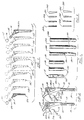
- FIGURES 1 - 5 illustrate generally the preferred embodiment of the apparatus of the present invention designated generally by the numeral 10.
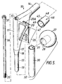
- a prosthesis body 11 which includes a widened mid-section 12, a lower elongated generally cylindrically shaped stem 13 and an upper neck 14.
- the mid-section includes an upper generally rectangular cross-sectional portion 15 and a lower generally rounded cross-sectional portion 16 which communicates with the generally cylindrical stem 13.
- the stem 13 includes three sections including an upper larger cylindrical section 17, a frustro-conical tapered transition section 18 and a lowermost smaller-diameter cylindrical portion 19.
- the prosthesis body 11 would preferably be supplied to hospitals and surgeons in kit form with a plurality of prosthesis bodies 11, modular pads 26, heads 27, collars 21, 22 and extension sleeves or distal sizers 30 being offered in various sizes such as is shown in FIGURES 1 - 2, including prosthesis bodies 11A - 11J, pads 26A-26H and sleeves 30, 30A.
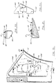
- Each prosthesis body 11 includes a generally U-shaped annular recess 20 which extends around one edge of the transitional mid-section 12 portion of the body 11 and is receptive of generally U-shaped collars 21 or 22 (FIGURE 2).
- Recess 20 has a shape corresponding to the inner edge portion 21C of collar 21.
- Collar 21 is thus generally U-shaped in plan view (FIGURE 13).
- Another embodiment of U-shaped collar 22 provides a similar, generally U-shaped body in plan view, but also includes a downwardly extending tab 23 which can be used to help transfer load between the prosthesis 10 and the femur where proximal bone tissue has eroded.
- Lock pin 21B extends through openings 20A, 21A in order to secure collars 21, 22 to prosthesis body 11.
- One of the openings 21A can be formed as a blind socket hole with a transverse closure wall 21D and thus not extend all the way to the outer surface of the collar so that the pin 21B cannot be driven too far and project from the outer surface of the collar 31.
- Each prosthesis body 11 includes a pair of left and right sockets 24, 25 which are receptive of one or more adjustment pads 26A - 26H.
- the cross-sectional configuration of each pad 26A - 26H can vary including thicker portions of the pad at the top as compared with the thickness at the bottom such as for example can be seen in FIGURE 4 with pad 26D and pad 26H which are thicker at one edge as compared with pads 26A and 26E.
- the pads 26A - 26H can be added by the surgeon to give a custom fit to the prosthesis body 11 in the area of the mid-section 12.
- Neck 14 is a frustroconically-shaped neck receptive of head 27 and of frustroconical neck extension sleeves 45.
- Head 27 provides a socket 28 corresponding in shape to neck 14.
- a plurality of heads 27 can be provided in various sizes as part of the kit, for matching each respective prosthesis body 11A - 11J.
- Each stem 13 is preferably rounded at its lower tip.
- the lowermost portion 19 of stem 13, which is of a smaller diameter, and the frustro-conical transition portion 18 of stem 13 form an attachment with a stem extension sleeve 30 (FIGURES 3, 5, 10, 11, and 14).
- the sleeve 30 is elongated and generally cylindrical and has an open end 31 which allows insertion of the stem 13 thereinto.
- the lowermost end portion of the sleeve 30 includes a generally curved distal end portion 32.
- Extension sleeve 30 is hollow providing a longitudinally extending bore 33 which extends between open end 31 and threaded aperture 34. Aperture 34 extends downwardly from bore 33, communicating with end 32. Threaded aperture 34 is receptive of the external threads 35 of a draw bolt 36.
- Bolt 36 includes an uppermost head portion 37 and a lower threaded portion 35.
- Prosthesis body 11 thus includes a longitudinally extending central bore 11A that is receptive of elongated bolt 36.
- extension sleeves 30, 30A includes a frustro-conical inner annular surface (FIGURES 3 and 11) which corresponds in shape to the frustro-conical transition portion 18 of stem 13 so that extension sleeves 30, 30A and stem 13 can form a frictional tight fit upon assembly (see FIGURE 14).
- Draw bolt 36 would be tightened after placement of prosthesis body 11 and a sleeve 30 or 30A into the intramedullary canal.
- the extension sleeve 30 or 30A can have a flexibility by using a thin wall thickness, for example, so that it is free to track the natural path of the intramedullary canal during insertion. After insertion, bolt 36 is tightened, drawing the frustro-conical inner surface of sleeve 30, 30A and transition portion 18 of stem 13 together.
- Extension sleeve 30 can be a short version having a longitudinally extending bore 33 which communicates with aperture 34, extending to end 32.
- extension sleeve 30A can be elongated extending well beyond threaded aperture 34.
- the longitudinal axis of extension sleeve 30A can change angle slightly or have a curvature in order to track the intramedullary canal, with the lower end portion 39 of each extension sleeve 30A being solid and being slightly skewed with respect to the longitudinal axis of open bore 33.
- extension sleeve 30A This allows the extension sleeve 30A to track the natural path of the intramedullary canal which is not perfectly straight nor a pure elongated cylinder.
- the elongated extension sleeves 30A can curve or bow to conform naturally to the femur of a patient for a custom fit.
- a plurality of heads 27 of differing sizes would be provided.
- the distance between the prosthesis body and the head 27 could be varied using extension members 45 or 50.
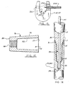
- Extension member 45 would be a hollowed trunion structure, having a conical outer surface 46 and a corresponding conical inner surface 47.
- a smaller open end portion 48 and a larger open end portion 49 define therebetween a bore which is occupied by neck 14 upon assembly of extension member 45 thereupon. Because of the smaller end 48, a head 27 could simply be slipped upon the extension member 45 with the socket 28 of head 27 registering upon the outer surface 46 of the extension member 45.
- An impact driver could load a selected extension member on the head 27 with a predetermined load, with the conical surfaces fitting tightly together.
- extension members 45 of differing lengths and of different cross-sectional dimensions would be provided to correspond to the plurality of differing neck sizes that accompany the plurality of prosthesis bodies as provided in kit form (see FIGURE 1).
- An alternative construction of neck extension members is shown in FIGURE 12 wherein the extension member 50 includes a conical outer surface 51, a conical inner surface 52 with a small end portion 53 having a threaded opening 54 that communicates with socket 56 at large diameter end portion 55 of extension member 50.
- the socket 28 of a particular selected head 27 would be registered tightly upon the end of extension member 50 in a wedge fit fashion.
- the threaded opening 54 would be threadably engaged with a removal tool in the form of an elongated shaft having one end portion which is threaded and the opposite end portion defining a handle, and/or an inertia weight sliding along the shaft, for example.
- pads 26 are shown as removably attached to prosthesis body 11. In FIGURE 15, it should be understood that only the assembly for securing one pad 24 or 25 is shown.
- the pads 26 are held in place by a single attachment mechanism that is carried generally between the pads 26 forming a connection therebetween.
- FIGURE 15 there is provided an annular bushing 61 which is an extension of each pad 26.
- Bushing 61 includes a plurality of arcuate members 62 - 65 with spaces 66 therebetween so that the bushing 61 can expand and grip the beveled annular wall 74 of opening 60 in prosthesis body 11 which is doubled.
- a bolt 70 is threadably attached to threaded bushing 61 so that the threads 72 of bolt 70 register with and threadably engage the threads 68 of bushing 61.
- the individual arcuate members 62 - 65 of bushing 61 expand (see arrows 73 of FIGURE 15) bearing against the annular wall 74 of opening 60.
- An opening 67 in pad 26 communicates with a tooled opening 71 in bolt 70 so that a tool such as an allen wrench for example can be inserted through opening 67 and into registration with the slot 71 which would be correspondingly shaped to receive the tool used.
- a single assembly bolt 80 is used to secure a pair of pads 26 together upon prosthesis body 11.
- the prosthesis body 11 includes a cylindrical transverse opening 79 which is occupied by annular bushing 81 integrally attached to pad 26.
- Bushing 81 includes an inner socket portion 83 which is threaded with internal threads 82.
- Assembly bolt 80 provides corresponding external threads 89 which threadably engage the threads 82 of bushing 81.
- a socket 88 is receptive of a tool such as an allen wrench for example and rotates therewith to tighten pads 26 together.
- Pad 26 provides a bushing 85 which carries an annular retaining ring 86, which can be a split ring or the like.
- An opening 90 allows access through pad 26 to the tooled opening 88.
- Assembly bolt 80 includes a generally circular annular head portion 91 which is held against pad 25 with ring 86. As the threaded bolt 80 is tightened, pads 26 are thus pulled together and tightly against prosthesis body 11.
- FIGURES 18-25 illustrate an alternate embodiment of the apparatus of the present invention wherein removable pads 40A, 40B attach to prosthesis body 11 with a wedge fit that self tightens the connection between each pad 40A, 40B and the prosthesis as hip joint reaction force pushes the prosthesis into the femur during use.
- a safety feature of each pad 40A, 40B and prosthesis body 11 connection is a locking member with tabs that force the surgeon to fully engage the pad 40A, 40B into a provided opening 100 on the prosthesis body 11 before a sliding of the pad 40A, 40B into locking engagement with the prosthesis body 11.
- FIGURE 19 there can be seen a fragmentary view of prosthesis body 11 having a socket 25 therein with a peripheral edge wall 25W. Similarly, the opposite side of prosthesis body 11 would have a socket 24 providing a peripheral side wall 25W. Each socket 24, 25 receives a modular pad 40A, 40B respectively.
- pad 40A is shown which registers during operation with the pad socket 24.
- the modular pad 40B would be a mirror image of the views shown for pad 40A of FIGURES 20-22.
- Each modular pad 40A, 40B carries on its rear surface 39 a wedge locking member 41 having a pair of opposed inclined locking surfaces 42 which form an acute angle with respect to one another, as shown in FIGURE 20.
- the locking member 41 carries a pair of tabs 43 which initially register at the enlarged end portion 100B of opening 100.
- the inclined lacking surfaces 42 of locking member 41 register with similarly shaped locking surfaces 101 of opening 100.
- the tabs 43 must be registered with the enlarged 100B end of opening 100. Otherwise, the locking member 41 will not fit into the opening 100.
- each pad 40A, 40B has a shape corresponding to the peripheral wall 24W, 25W of each socket 24, 25.
- the pads 40A, 40B are sized slightly smaller than the outer configuration of each socket 24, 25 as defined by their peripheral side walls, 24W, 25W. This provides room to move each pad 40A, 40B slightly so that sliding action can be used to perfect the wedge lock connection between each pad 40A, 40B and its respective socket 24, 25.
- the outer edge of each pad 40A, 40B would be spaced inwardly from the peripheral wall 24W, 25W of each socket 24, 25 by a small measure.
- each pad 40A, 40B and the prosthesis body 11 can be formed between each pad 40A, 40B and the prosthesis body 11 using an impact driver.
- each pad includes a generally flat lower surface 106.
- a similar flat surface 107 is provided at the bottom of each socket 24, 25.
- an impact driver can be used to tighten the pads 40A, 40B to the prosthesis body 11 using the impact driver.
- An impact driver is a commercially available product which carries a tooled end portion having, for example, a commercial screw driver tip or wedge tip. The impact driver tool tip (not shown) is then placed in the space formed between the surfaces 106 and 107 after the surgeon places the respective pads 40A, 40B in their respective sockets 24, 25.
- the prosthesis is placed on a flat surface and the surgeon simply presses downwardly on the impact driver, activating the tool tip portion of the impact driver to force the surface 106 away from the surface 107. The surgeon then turns the prosthesis over and repeats the same procedure for the second pad. It has been found that using a commercially available, relatively small impact driver, such as supplied by Starrett Company, as much as 300 pounds of load can be generated holding each pad 40A, 40B to the prosthesis body 11.
- the present invention provides a safety feature for continuously loading each pad 40A, 40B to the prosthesis body 11. This is insured because the pad outer surface 38 is typically beveled so that the bottom of the pad is narrower and the top of the pad is wider, as shown in FIGURES 21 and 22. Thus, when the pad is installed, it self tightens as the hip joint reaction force of the patient pushes the prosthesis further into the femur. The femur presses on the outer surface 38 of the pad, forcing it upwardly and further forcing the wedge lock surfaces 42 of each pad 40A, 40B against the surfaces 101 of the opening 100.
- An additional safety feature of the present invention is that the walls 24W, 25W of the sockets 24, 25 contain the pads 40A, 40B if the pads are inadvertently disengaged from the locking mechanism.
- Another safety feature of the present invention are the locking tabs 43 which force the surgeon to fully engage the pads 40A, 40B into their respective slots 24, 25 before attempting to slide the wedge inclined locking surfaces 42 into engagement with the locking surfaces 101. If the surgeon does not fully engage the pads 40A, 40B into opening 101, the locking tabs prevent wedge locking of the surface 42 to the surface 101.
- the present invention provides thus a simple and quick modular pad construction that allows for installing different contours on either the anterior or posterior side of the prosthesis so that the femoral cavity can be completely filled in order to obtain a better bone-prosthesis contact.
- the present invention could be supplied with a number of trial sockets in kit forms so that the kit could be used to size the apparatus perfectly. Then, the surgeon would have the actual prosthesis and its modular pads in pre-packaged sterilized condition. Thus, the surgeon could use the trial kit to size the prosthesis and its modular parts and then simply open the corresponding part from a sterile package when the correct fit had been obtained.
- FIGURES 26 - 29 illustrate an alternate embodiment of the distal sizer designated by the numeral 120 in FIGURE 26.
- Distal sizer 120 includes a lower hemispherically-shaped distal end portion 121 and upper end portion 122 which attaches to the stem 13 of prosthesis body 11 of FIGURES 1, 2 and 5.
- a bore 123 communicates with the uppermost or proximal end 122 of distal sizer 120.
- Bore 123 includes a frustroconical section 124 and a generally cylindrical section 125 terminating at conically-shaped end portion 126.
- the distal sizer 120 provides a curved section 128 that begins at the middle 127 portion of the distal sizer 120 and terminates at distal end 121 thereof.
- a distal sizer 130 having a bore 131 which includes a frustroconical portion 132, a generally cylindrical section 133, and a conical end portion 134.
- the prosthesis 130 outer wall 135 is generally cylindrically shaped.
- the lower or distal end portion 136 provides a pair of longitudinally extending and intersecting slots 137, 138.
- the slots 137, 138 form a plurality of distal sizer segments 139-142, as shown in FIGURE 28.
- Each of the slots 138, 137 terminates at 143 which is at the central portion of distal sizer 130.
- a single slot 137 is illustrated which forms a pair of distal sizer segments 144, 145.
- the distal sizer would be constructed like the embodiment of FIGURE 27 with the exception that a single slot 137 is provided rather than the two slots 137, 138 of the embodiment of FIGURES 27-28.
- Distal sizer 150 provides a hemispherically-shaped lower end portion 151 and an upper end portion 152.
- the distal sizer 150 is provided with an internal bore of the shape and configuration of the bores 131 of FIGURES 26 and 27. This would provide for attachment of the sizer 152 to the stem 13 of prosthesis body 11 of FIGURE 5, for example.
- the distal sizer 150 is generally cylindrically shaped in cross-section but provides a plurality of circumferentially spaced, longitudinally extending projections 153.
- Each projection 153 has a trough 154 and a pair of sidewall 155, 156 portions with a crest 157 between adjacent projections 153.
Abstract
A modular hip prosthesis can be custom fitted to a particular patient by a surgeon prior to surgical insertion. The prosthesis features a body (11) having a neck portion for carrying a rounded head element (27), a transitional mid-section (12) of the prosthesis body includes generally rectangular (15) and generally rounded (16) cross-sectional areas, and a stem section (13) has a generally rounded cross-sectional area. The stem (13) is tapered to receive a tubular extension sleeve (30) with a hollowed portion corresponding in shape to the stem portion (13) of the prosthesis. The tubular extension sleeve (30) has an open end portion receptive of the lower tapering stem (19) of the prosthesis body. The stem portion (13) includes an internal bore, and an attachment in the form of an elongated screw (36) is provided for connection to the stem internal bore for securing the extension sleeve (30) and the prosthesis body (11) together, forming a compressive sealed connection therebetween. Pads (26) can be attached to the transitional mid-section (12) of the prosthesis body (11) for increasing the cross-sectional shape of the prosthesis at the transitional mid-section. The pads (26) are loaded continuously to connect to the prosthesis body by the hip joint reaction force. Removable collars can be added to the prosthesis to form a transverse load carrying interface with the upper end of the patient's femur. Frustroconically-shaped extension sleeves (45) can be added to the prosthesis neck (14) for extending the neck length.
Description
- This is a continuation-in-part of copending U.S. Patent Application Serial No. 07/470,751, filed 1/31/90, now U.S. Patent No. 5,108,452, which is a continuation-in-part of U.S. Patent Application Serial No. 07/308,205, filed 2/8/89, now U.S. Patent No. 4,995,883, all hereby incorporated herein by reference.
- The present invention relates to a modular hip prosthesis system wherein various component parts of an implant kit can be selected during the surgical procedure so that the implant can be custom fitted to a patient, and including removable modular anterior and posterior pads that can be of a variety of custom configurations and sizes are secured with a wedge lock fit connection that continuously self tightens the pads to the prosthesis body during use, as the hip joint reaction force pushes the prosthesis into the femur. Other modular features include removable neck extensions, distal sizers, and modular collars.
- Increasingly, surgeons want to be able to custom fit femoral prostheses to patients. Instead of having to choose a properly sized prosthesis from a group of pre-formed implants, it would be advantageous to have a basic design which can be modified with various component parts. This would eliminate the need to maintain a large inventory and would provide better fitting implants.
- Custom fitted implants are particularly important in revision cases where an implant has to be removed and replaced since old cement must be removed and bone resorption occurs in many cases. Unpredictable, proximal and/or distal bone loss or deformity often occurs which must be accommodated by the replacement prosthesis.
- For initial implants, basic variations in patient anatomy are often confronted by the surgeon. Some patients have femoral necks that can be significantly longer or shorter than others. Cortical shaft defects, which are not uncommon, are not discovered until during operation. Variations in intramedullary canal diameter can also occur, which if not accompanied by a properly sized implant, can result in distal toggle.
- In short, it is difficult, if not impossible, to predict the exact shape of a hip implant which is suitable for all patients. Since it is impractical and would be prohibitively expensive to maintain an inventory of implants for most patients, compromises must sometimes be made in supplying implants which fit reasonably well but could be improved upon.
- Several hip prostheses are known which are formed of replaceable or interchangeable component parts.
- U.S. Patent No. 3,641,590 entitled "Acetabular Replacement Prosthesis and Method of Assembling" issued to Michele discloses a selective individualized technique for acetabulum socket replacement per se, or in conjunction with a hip replacement prosthesis (referring to the Michele U.S. Pat. No. 3,228,393) for a total hip replacement, designed for all ages including the very young. A selective anchorage for a cup prosthesis of a size selected from the limited number of differently sized cups is made available. Anchorage of the acetabular socket replacement conforms to variations in dimensions, shapes and positions of the (medullary) canals of the acetabulum pelvis of the individual patient and includes at least two elongated and convergent or divergent fasteners.
- A removable collar of low modulus of elasticity material is shown in U.S. Patent No. 4,012,796 entitled "Interpositioning Collar For Prosthetic Bone Insert" issued to Weisman et al. The collar is interpositioned between a collar of a metal prosthetic hip stem implanted in the intramedullary canal of the femur and the adjacent calcar or outer edge of the bone. A flange depends from the insert between the upper portion of the stem and the inner wall of the bone. The interpositioned collar is either a full elongated tapered O-shape or it is open on one side of a tapered U-shape.
- U.S. Patent No. 4,404,691 entitled "Modular Prosthesis Assembly" issued to Buning et al., provides a modular hip prosthesis assembly for replacement of at least part of a joint and part of a bone shaft including a mounting component provided with a connection portion and at least two joint components of similar shape but different dimensions and which can be connected alternatively to the mounting component, each of the joint components having an engagement portion and a connection part adapted for connection to the connection portion of the mounting component, the joint components each providing part of a bone shaft and part of a joint which can cooperate with an appropriate part of a natural or artificial joint.
- U.S. Patent No. 4,578,081 entitled "Bone Prosthesis" issued to Harder et al., discloses a bone prosthesis comprising at least one joint component replacing a natural joint half, which is provided with a shank adapted to be connected to the bone, wherein a set of joint components is provided, and the shank is designed as a bone replacement member, with a connection portion provided adapted to be connected to the bone at one end and at the other end to the shank. One of the components is a hip prosthesis with a rounded head and a hollowed hip component that connects to elongated mounting components. In another hip prosthesis embodiment, a neck with a cone shape receives a suitable joint head with an inner cone.
- A femoral component for hip prosthesis is shown in U.S. Patent No. 4,608,055 issued to Morrey et al., the prosthesis disclosed in the '055 patent includes a stem portion and a combined integral head and neck portion. The stem portion includes a proximal portion and a distal portion which are angularly related with respect to one another and with the proximal portion including a recess formed therein for receipt of the tapered portion of the head and neck component. The head and neck component includes a substantially part spherical head portion attached to a neck portion and a tapered portion angularly attached to the neck portion via a basilar neck portion with the tapered portion being adapted to be permanently inserted into the recess portion of the proximal end of the above described stem portion. The stem portion includes a plurality of recesses on the periphery and longitudinal extent thereof for receiving fiber metal pads which are provided to allow boney ingrowth therein in order to retain the femoral component permanently installed in the proximal end of the femur.
- In U.S. Patent No. 4,676,797 entitled "Unit For Resection Prosthesis", a resection prosthesis assembly unit includes a head member, an end member and an intermediate member between the head and end members, of which one member is provided with a conical pin and another member is provided with a conical pin and another member is provided with a conical bore. The latter two members are provided with respective first surfaces that extend transversely to an insertion direction and which face one another and are spaced apart to define a recess when the two members are connected together. One of the two members is further provided with a second surface extending in the insertion direction, and the recess being provided to receive a wedge insertable into the recess to bear against the first surfaces for forcing the two members apart while the forces exerted by the wedge are absorbed by the first surfaces and the wedge is guided by the second surface.
- Additionally, end fitting distal sizers attached in a similar fashion could allow the surgeon to tailor the prosthesis tip to the canal diameter thereby reducing distal toggle.
- The present invention provides a modular hip prosthesis which can be custom fitted to a particular patient by a surgeon prior to surgical insertion of the prosthesis.
- The apparatus includes a prosthesis body having a generally wider larger, i.e., upper mid-section portion and an upper neck adapted for carrying a rounded head portion that fits either the patient's acetabulum or a prosthetic acetabular component.
- A lower stem extends from the mid-section and terminates at a lower rounded tip. The stem is adapted for placement in the intramedullary canal of the patient's femur. Distal stem sizers are provided which allows the length of the femoral shaft to be augmented with extensions that lock with the primary shaft using a tapered attachment. This attachment allows the surgeon to extend the stem length beyond any cortical shaft defect he may encounter intraoperatively.
- The distal sizer in preferably the form of a tubular stem extension sleeve includes a hollowed portion corresponding in shape to the stem. The sizer includes an open end portion which is receptive of the stem for insertion thereinto. The lower stem portion includes an internal bore. Corresponding frustroconical surfaces of the distal sizer and stem allow a tight fit to be achieved between distal sizer and stem. In another embodiment, an attachment member, preferably in the form of a threaded draw bolt, forms an attachment between the internal bore of the stem and the extension sleeve holding the extension sleeve to the prosthesis body.
- The stem and sleeve corresponding tapered or frustroconical surfaces form a tight friction fit which seals wear particles from body tissues that typically wear off during insertion of the stem to the sleeve. A commercially available impact driver tool can load the sleeve to the stem, and the corresponding tapered regions register very tightly together forming a seal and an interference like fit.
- In one embodiment, when a draw bolt is tightened, its non-threaded end presses against the hip stem to provide tension in the bolt and compressive force between the stem and sleeve in corresponding tapered regions of the stem and sleeve.
- The tubular stem extension sleeve is of a generally uniform cross-section. Its upper end has an annular tapered section that registers with correspondingly tapered section of the stem. The prosthesis body in one embodiment has a longitudinal central open ended bore that extends substantially the length of the prosthesis body. The attachment includes an elongated fastener, preferably an elongated threaded bolt that is adapted for placement within the elongated bore, extending substantially the length of the bore upon assembly. The bolt provides an upper head end portion which can be manipulated by the surgeon at the top of the prosthesis for tightening or loosening the fit between the sleeve and prosthesis body.
- The stem extension sleeve provides a threaded section that can engage the lower end portion of the bolt to form a threaded connection. This attachment of sleeve and prosthesis body can also be made using a very short bolt which is affixed through an opening in the bottom of the extension sleeve, and into a bore in the bottom of the stem. The stem extension sleeves can be of varying lengths and diameters, and can be straight or curved. The sleeve hollow bore portion can extend substantially the length of the sleeve, or can extend a partial distance along the sleeve.
- The assembly draw bolt can be tightened after the prosthesis and extension sleeve are in position so that the extension can twist to track the intermedullary canal during insertion. After placement, the draw bolt can be used to lock the extension and prosthesis body together.
- The prosthesis body has a frustroconically-shaped neck portion for carrying a rounded head element. Between the neck portion and the distal end is a transitional mid-section having generally rectangular upper cross-sectional area and a generally rounded lower cross-sectional area. Extension sleeves having conical inner and outer surfaces and can be added to the neck portion for elongating the neck portion with respect to the prosthesis body and the head.
- Removable transverse bearing collars can be adjustably affixed to the mid-section of the prosthesis body, generally transverse to the longitudinal axis of the prosthesis body for forming a load carrying interface between the prosthesis body and the upper end of the patient's femur. In one embodiment, the removable bearing collar can have extensions that will compensate for proximal bone loss, i.e. at the top of the patient's femur.
- Removable pads are attachable to the mid-section of the prosthesis for changing the cross-sectional configuration of the prosthesis at the mid-section. One or more sockets are formed in the prosthesis at the mid-section for carrying the modular pads. In one embodiment, a wedge lock connection secures each pad to the prosthesis body. A locking member on the back of each pad locks each pad to the prosthesis at corresponding engaging wedge surfaces thereon. The pads each carry corresponding locking tab members which insure complete interlocking engagement of the pads to the prosthesis body before forming the wedge lock connection. This safety feature requires that the surgeon fully engage each pad into its socket before being able to slide the pad into the wedge-lock position. The tabs on the locking member of each pad engage a recess or undercut in the socket of the prosthesis body to constrain the pad from moving in a direction away from the prosthesis body, after assembly is completed.
- Pad shape can be varied to custom fit the patient's anatomy maximizing stability to transfer shear load or compression load between the prosthesis and the patient's bone as desired. The pads can be of differing materials such as porous or roughened coatings to promote tissue ingrowth or on growth. Also, manufacturing methods which might weaken the integrity of the prosthesis body, such as the addition of a coating of beads, can be used for the removable pads, thus not affecting the structural integrity of the prosthesis body.
- For a further understanding of the nature and objects of the present invention, reference should be had to the following detailed description, taken in conjunction with the accompanying drawings, in which like parts are given like reference numerals, and wherein:
- FIGURE 1 is a side view illustrating a plurality of hip prosthesis bodies as used with the modular hip system of the present invention;
- FIGURE 2 is a side view of a pair of hip prosthesis bodies of differing sizes illustrating insertion of the modular collar portions thereof;
- FIGURE 3 is a side view illustrating a plurality of sleeve extension parts as used in the modular hip prosthesis system of the present invention;
- FIGURE 4 is a side view of a plurality of modular pads for use with the hip prosthesis bodies of FIGURES 1 and 2, illustrating varying pad cross-sectional configurations;
- FIGURE 5 is a perspective exploded view illustrating the preferred embodiment of the apparatus of the present invention;
- FIGURE 6 is a top view of the prosthesis body portion of the preferred embodiment of the apparatus of the present invention;
- FIGURE 7 is a side view of the prosthesis body portion of the preferred embodiment of the apparatus of the present invention;
- FIGURES 8 and 9 are top and side views illustrating the assembly bolt portion of the preferred embodiment of the apparatus of the present invention;
- FIGURES 10 and 11 are top and side sectional views of the stem extension sleeve portions of the preferred embodiment of the apparatus of the present invention;
- FIGURE 12 is a sectional view illustrating an alternate construction of the neck extension sleeve portion of the preferred embodiment of the apparatus of the present invention;
- FIGURE 13 is a plan view illustrating the modular collar portion of the preferred embodiment of the apparatus of the present invention;
- FIGURE 14 is a partial sectional view illustrating the preferred embodiment of the apparatus of the present invention with the prosthesis body and stem extension sleeve assembled;
- FIGURE 15 is a sectional elevational fragmentary view illustrating the assembly of modular pads to the prosthesis body;
- FIGURE 16 is a sectional view taken along 16 - 16 of FIGURE 15;
- FIGURE 17 is a sectional elevational view of a second construction of the preferred embodiment of the apparatus of the present invention illustrating the assembly of the modular pads to the prosthesis body;
- FIGURE 18 is a side exploded view of a second embodiment of the modular hip prosthesis pads of the present invention;
- FIGURE 19 is a side fragmentary view of the second embodiment of the modular hip prosthesis of the present invention;
- FIGURE 20 is a rear view illustrating the construction of the modular pad of the second embodiment of the apparatus of the present invention;
- FIGURE 21 is a side view illustrating the construction of the modular pad of the second embodiment of the apparatus of the present invention;
- FIGURE 22 is an end view illustrating the construction of the modular pad of the second embodiment of the apparatus of the present invention.
- FIGURE 23 is a sectional view taken along lines 23-23 of FIGURE 19;
- FIGURE 24 is a sectional view taken along lines 24-24 of FIGURE 19; and
- FIGURE 25 is a sectional view taken along lines 25-25 of FIGURE 19.
- FIGURE 26 is a side sectional view of a distal sizer for use with the modular hip prosthesis system of the present invention;
- FIGURE 27 is a side view of an alternate embodiment of the distal sizer portion of the modular hip prosthetic system of the present invention;
- FIGURE 28 is a sectional view taken along lines 28-28 of FIGURE 27;
- FIGURE 29 is an end view of the distal sizer of FIGURE 27;
- FIGURE 30 is a side view of another alternate embodiment of the distal sizer portion of the modular hip prosthesis system of the present invention;
- FIGURE 31 is a sectional view taken along lines 31-31 of FIGURE 30.
- FIGURES 1 - 5 illustrate generally the preferred embodiment of the apparatus of the present invention designated generally by the numeral 10. In FIGURE 5 there can be seen a
prosthesis body 11 which includes a widenedmid-section 12, a lower elongated generally cylindrically shapedstem 13 and anupper neck 14. The mid-section includes an upper generally rectangularcross-sectional portion 15 and a lower generally roundedcross-sectional portion 16 which communicates with the generallycylindrical stem 13. - The
stem 13 includes three sections including an upper largercylindrical section 17, a frustro-conicaltapered transition section 18 and a lowermost smaller-diametercylindrical portion 19. Theprosthesis body 11 would preferably be supplied to hospitals and surgeons in kit form with a plurality ofprosthesis bodies 11,modular pads 26, heads 27,collars distal sizers 30 being offered in various sizes such as is shown in FIGURES 1 - 2, includingprosthesis bodies 11A - 11J,pads 26A-26H andsleeves - Each
prosthesis body 11 includes a generally U-shapedannular recess 20 which extends around one edge of thetransitional mid-section 12 portion of thebody 11 and is receptive of generallyU-shaped collars 21 or 22 (FIGURE 2).Recess 20 has a shape corresponding to the inner edge portion 21C ofcollar 21.Collar 21 is thus generally U-shaped in plan view (FIGURE 13). Another embodiment ofU-shaped collar 22 provides a similar, generally U-shaped body in plan view, but also includes a downwardly extendingtab 23 which can be used to help transfer load between the prosthesis 10 and the femur where proximal bone tissue has eroded. - Lock pin 21B (FIGURE 13) extends through
openings collars prosthesis body 11. One of theopenings 21A can be formed as a blind socket hole with a transverse closure wall 21D and thus not extend all the way to the outer surface of the collar so that the pin 21B cannot be driven too far and project from the outer surface of thecollar 31. - Each
prosthesis body 11 includes a pair of left andright sockets more adjustment pads 26A - 26H. The cross-sectional configuration of eachpad 26A - 26H can vary including thicker portions of the pad at the top as compared with the thickness at the bottom such as for example can be seen in FIGURE 4 withpad 26D andpad 26H which are thicker at one edge as compared withpads pads 26A - 26H can be added by the surgeon to give a custom fit to theprosthesis body 11 in the area of the mid-section 12. -
Neck 14 is a frustroconically-shaped neck receptive ofhead 27 and of frustroconicalneck extension sleeves 45.Head 27 provides asocket 28 corresponding in shape toneck 14. A plurality ofheads 27 can be provided in various sizes as part of the kit, for matching eachrespective prosthesis body 11A - 11J. - Each stem 13 is preferably rounded at its lower tip. The
lowermost portion 19 ofstem 13, which is of a smaller diameter, and the frustro-conical transition portion 18 ofstem 13 form an attachment with a stem extension sleeve 30 (FIGURES 3, 5, 10, 11, and 14). Thesleeve 30 is elongated and generally cylindrical and has anopen end 31 which allows insertion of thestem 13 thereinto. The lowermost end portion of thesleeve 30 includes a generally curveddistal end portion 32. -
Extension sleeve 30 is hollow providing alongitudinally extending bore 33 which extends betweenopen end 31 and threadedaperture 34.Aperture 34 extends downwardly frombore 33, communicating withend 32. Threadedaperture 34 is receptive of theexternal threads 35 of adraw bolt 36.Bolt 36 includes anuppermost head portion 37 and a lower threadedportion 35.Prosthesis body 11 thus includes a longitudinally extendingcentral bore 11A that is receptive ofelongated bolt 36. - The upper end portion of
extension sleeves conical transition portion 18 ofstem 13 so thatextension sleeves bolt 36 would be tightened after placement ofprosthesis body 11 and asleeve extension sleeve bolt 36 is tightened, drawing the frustro-conical inner surface ofsleeve transition portion 18 ofstem 13 together. -
Extension sleeve 30 can be a short version having alongitudinally extending bore 33 which communicates withaperture 34, extending to end 32. In another embodiment (see FIGURE 3),extension sleeve 30A can be elongated extending well beyond threadedaperture 34. As shown in the longer sleeve in Fig. 3, the longitudinal axis ofextension sleeve 30A can change angle slightly or have a curvature in order to track the intramedullary canal, with thelower end portion 39 of eachextension sleeve 30A being solid and being slightly skewed with respect to the longitudinal axis ofopen bore 33. This allows theextension sleeve 30A to track the natural path of the intramedullary canal which is not perfectly straight nor a pure elongated cylinder. Thus, theelongated extension sleeves 30A can curve or bow to conform naturally to the femur of a patient for a custom fit. - A plurality of
heads 27 of differing sizes would be provided. The distance between the prosthesis body and thehead 27 could be varied usingextension members Extension member 45 would be a hollowed trunion structure, having a conicalouter surface 46 and a corresponding conicalinner surface 47. A smalleropen end portion 48 and a larger open end portion 49 define therebetween a bore which is occupied byneck 14 upon assembly ofextension member 45 thereupon. Because of thesmaller end 48, ahead 27 could simply be slipped upon theextension member 45 with thesocket 28 ofhead 27 registering upon theouter surface 46 of theextension member 45. An impact driver could load a selected extension member on thehead 27 with a predetermined load, with the conical surfaces fitting tightly together. In the preferred embodiment,extension members 45 of differing lengths and of different cross-sectional dimensions would be provided to correspond to the plurality of differing neck sizes that accompany the plurality of prosthesis bodies as provided in kit form (see FIGURE 1). An alternative construction of neck extension members is shown in FIGURE 12 wherein theextension member 50 includes a conicalouter surface 51, a conicalinner surface 52 with asmall end portion 53 having a threadedopening 54 that communicates withsocket 56 at largediameter end portion 55 ofextension member 50. Thus, thesocket 28 of a particular selectedhead 27 would be registered tightly upon the end ofextension member 50 in a wedge fit fashion. In order to remove themember 50 fromneck 14, the threadedopening 54 would be threadably engaged with a removal tool in the form of an elongated shaft having one end portion which is threaded and the opposite end portion defining a handle, and/or an inertia weight sliding along the shaft, for example. - In FIGURES 15 - 17,
pads 26 are shown as removably attached toprosthesis body 11. In FIGURE 15, it should be understood that only the assembly for securing onepad - In the embodiment of FIGURE 17, the
pads 26 are held in place by a single attachment mechanism that is carried generally between thepads 26 forming a connection therebetween. - In the embodiment of FIGURE 15 there is provided an
annular bushing 61 which is an extension of eachpad 26.Bushing 61 includes a plurality of arcuate members 62 - 65 withspaces 66 therebetween so that thebushing 61 can expand and grip the beveledannular wall 74 of opening 60 inprosthesis body 11 which is doubled. Abolt 70 is threadably attached to threadedbushing 61 so that thethreads 72 ofbolt 70 register with and threadably engage the threads 68 ofbushing 61. Upon such threadable connection, the individual arcuate members 62 - 65 ofbushing 61 expand (seearrows 73 of FIGURE 15) bearing against theannular wall 74 ofopening 60. Anopening 67 inpad 26 communicates with atooled opening 71 inbolt 70 so that a tool such as an allen wrench for example can be inserted throughopening 67 and into registration with theslot 71 which would be correspondingly shaped to receive the tool used. - In the embodiment of FIGURE 17, a
single assembly bolt 80 is used to secure a pair ofpads 26 together uponprosthesis body 11. Theprosthesis body 11 includes a cylindricaltransverse opening 79 which is occupied byannular bushing 81 integrally attached to pad 26.Bushing 81 includes aninner socket portion 83 which is threaded withinternal threads 82.Assembly bolt 80 provides correspondingexternal threads 89 which threadably engage thethreads 82 ofbushing 81. Asocket 88 is receptive of a tool such as an allen wrench for example and rotates therewith to tightenpads 26 together.Pad 26 provides abushing 85 which carries anannular retaining ring 86, which can be a split ring or the like. Anopening 90 allows access throughpad 26 to the tooledopening 88.Assembly bolt 80 includes a generally circularannular head portion 91 which is held againstpad 25 withring 86. As the threadedbolt 80 is tightened,pads 26 are thus pulled together and tightly againstprosthesis body 11. - FIGURES 18-25 illustrate an alternate embodiment of the apparatus of the present invention wherein
removable pads 40A, 40B attach to prosthesisbody 11 with a wedge fit that self tightens the connection between eachpad 40A, 40B and the prosthesis as hip joint reaction force pushes the prosthesis into the femur during use. A safety feature of eachpad 40A, 40B andprosthesis body 11 connection is a locking member with tabs that force the surgeon to fully engage thepad 40A, 40B into a providedopening 100 on theprosthesis body 11 before a sliding of thepad 40A, 40B into locking engagement with theprosthesis body 11. - In FIGURE 19, there can be seen a fragmentary view of
prosthesis body 11 having asocket 25 therein with aperipheral edge wall 25W. Similarly, the opposite side ofprosthesis body 11 would have asocket 24 providing aperipheral side wall 25W. Eachsocket modular pad 40A, 40B respectively. In FIGURES 19-22,pad 40A is shown which registers during operation with thepad socket 24. The modular pad 40B would be a mirror image of the views shown forpad 40A of FIGURES 20-22. - Each
modular pad 40A, 40B carries on its rear surface 39 awedge locking member 41 having a pair of opposed inclined locking surfaces 42 which form an acute angle with respect to one another, as shown in FIGURE 20. During use, the surgeon placesmodular pad 40A into its similarly shapedsocket 24 registering the lockingmember 41 intoopening 100. The lockingmember 41 carries a pair oftabs 43 which initially register at the enlarged end portion 100B ofopening 100. Similarly, the inclined lackingsurfaces 42 of lockingmember 41 register with similarly shaped lockingsurfaces 101 ofopening 100. Thetabs 43 must be registered with the enlarged 100B end ofopening 100. Otherwise, the lockingmember 41 will not fit into theopening 100. This provides a safety feature because the surgeon must fully place theparticular pad 40A, 40B into itssocket pad 40A, 40B to theprosthesis body 11. Once the lockingmember 41 has been fully registered within theopening 100, the surgeon then simply slides the pad upwardly toward theupper end 15 of theprosthesis body 11. Thetabs 43 then slide undershoulders 102 and register inundercut slots 103, as shown in FIGURE 24. As eachpad 40A, 40B is moved into locking position by the surgeon, thesurfaces 42 of thewedge locking member 41 engage theinclined surfaces 101 of theopening 100. A tight wedge-lock fit is obtained by forcing thesurfaces pad 40A, 40B secures tightly to the prosthesis body because thesurfaces 42 wedge fit to thesurfaces 101. - In the preferred embodiment, the outer periphery of each
pad 40A, 40B has a shape corresponding to theperipheral wall socket pads 40A, 40B are sized slightly smaller than the outer configuration of eachsocket pad 40A, 40B slightly so that sliding action can be used to perfect the wedge lock connection between eachpad 40A, 40B and itsrespective socket pad 40A, 40B would be spaced inwardly from theperipheral wall socket - A very tight wedge lock connection can be formed between each
pad 40A, 40B and theprosthesis body 11 using an impact driver. In the preferred embodiment, each pad includes a generally flatlower surface 106. A similarflat surface 107 is provided at the bottom of eachsocket pads 40A, 40B to theprosthesis body 11 by the surgeon, an impact driver can be used to tighten thepads 40A, 40B to theprosthesis body 11 using the impact driver. An impact driver is a commercially available product which carries a tooled end portion having, for example, a commercial screw driver tip or wedge tip. The impact driver tool tip (not shown) is then placed in the space formed between thesurfaces respective pads 40A, 40B in theirrespective sockets surface 106 away from thesurface 107. The surgeon then turns the prosthesis over and repeats the same procedure for the second pad. It has been found that using a commercially available, relatively small impact driver, such as supplied by Starrett Company, as much as 300 pounds of load can be generated holding eachpad 40A, 40B to theprosthesis body 11. - In the event that one of the
pads 40A or 40B were to become loose, because the surgeon possibly did not apply enough force to the pad in order to wedge lock it to theprosthesis body 11, the present invention provides a safety feature for continuously loading eachpad 40A, 40B to theprosthesis body 11. This is insured because the padouter surface 38 is typically beveled so that the bottom of the pad is narrower and the top of the pad is wider, as shown in FIGURES 21 and 22. Thus, when the pad is installed, it self tightens as the hip joint reaction force of the patient pushes the prosthesis further into the femur. The femur presses on theouter surface 38 of the pad, forcing it upwardly and further forcing the wedge lock surfaces 42 of eachpad 40A, 40B against thesurfaces 101 of theopening 100. - An additional safety feature of the present invention is that the
walls sockets pads 40A, 40B if the pads are inadvertently disengaged from the locking mechanism. - Another safety feature of the present invention are the locking
tabs 43 which force the surgeon to fully engage thepads 40A, 40B into theirrespective slots surfaces 42 into engagement with the locking surfaces 101. If the surgeon does not fully engage thepads 40A, 40B intoopening 101, the locking tabs prevent wedge locking of thesurface 42 to thesurface 101. - The present invention provides thus a simple and quick modular pad construction that allows for installing different contours on either the anterior or posterior side of the prosthesis so that the femoral cavity can be completely filled in order to obtain a better bone-prosthesis contact. The present invention could be supplied with a number of trial sockets in kit forms so that the kit could be used to size the apparatus perfectly. Then, the surgeon would have the actual prosthesis and its modular pads in pre-packaged sterilized condition. Thus, the surgeon could use the trial kit to size the prosthesis and its modular parts and then simply open the corresponding part from a sterile package when the correct fit had been obtained.
- FIGURES 26 - 29 illustrate an alternate embodiment of the distal sizer designated by the numeral 120 in FIGURE 26.
Distal sizer 120 includes a lower hemispherically-shapeddistal end portion 121 andupper end portion 122 which attaches to thestem 13 ofprosthesis body 11 of FIGURES 1, 2 and 5. In FIGURE 26, abore 123 communicates with the uppermost orproximal end 122 ofdistal sizer 120. -
Bore 123 includes afrustroconical section 124 and a generallycylindrical section 125 terminating at conically-shapedend portion 126. Thedistal sizer 120 provides acurved section 128 that begins at the middle 127 portion of thedistal sizer 120 and terminates atdistal end 121 thereof. - In the embodiment of FIGURE 27, a
distal sizer 130 is provided having abore 131 which includes a frustroconical portion 132, a generally cylindrical section 133, and a conical end portion 134. Theprosthesis 130outer wall 135 is generally cylindrically shaped. The lower ordistal end portion 136 provides a pair of longitudinally extending and intersectingslots slots slots distal sizer 130. - In the embodiment of FIGURE 29, a
single slot 137 is illustrated which forms a pair ofdistal sizer segments single slot 137 is provided rather than the twoslots - In FIGURES 30-31, a further embodiment of the distal sizer is provided designated as 150.
Distal sizer 150 provides a hemispherically-shapedlower end portion 151 and anupper end portion 152. Thedistal sizer 150 is provided with an internal bore of the shape and configuration of thebores 131 of FIGURES 26 and 27. This would provide for attachment of thesizer 152 to thestem 13 ofprosthesis body 11 of FIGURE 5, for example. - The
distal sizer 150 is generally cylindrically shaped in cross-section but provides a plurality of circumferentially spaced, longitudinally extendingprojections 153. Eachprojection 153 has atrough 154 and a pair ofsidewall crest 157 betweenadjacent projections 153. - Because many varying and different embodiments may be made within the scope of the inventive concept herein taught, and because many modifications may be made in the embodiments herein detailed in accordance with the descriptive requirement of the law, it is to be understood that the details herein are to be interpreted as illustrative and not in a limiting sense.
Claims (34)
- A modular hip prosthesis that can be custom fitted to a particular patient by a surgeon prior to surgical insertion, comprising:a) a hip prosthesis body having an upper end portion with a neck adapted for carrying a rounded head portion that fits the patient's acetabulum, a mid-section with anterior and posterior sides and a lower stem portion adapted for placement in the intramedullary canal of the patient's femur;b) removable proximal and distal extension members attachable respectively to the neck and stem for selectively conforming the prosthesis to the adjacent acetabulum and femoral bone tissue by selectively increasing the prosthesis neck for spacing the rounded head portion away from the mid portion along a line that intersects the patient's acetabular socket and/or increasing the stem length below the mid-section; and on either or both sides thereof;c) each member having holding means for attaching each respective member to the prosthesis body the holding means including corresponding frustroconical surfaces on each extension member and on the prosthesis body; andd) wherein the prosthesis body includes a first of said frustroconical surfaces on the prosthesis body neck and a second of said frustroconical surfaces at the upper end portion of the stem.
- The modular hip prosthesis of Claim 1 wherein the distal stem extension member has a bore of a generally uniform cross-section along a majority of its length.
- The modular hip prosthesis of Claim 1 wherein the distal stem extension member is substantially straight.
- The modular hip prosthesis of Claim 1 wherein the distal stem extension member is curved to conform to the shape of the intramedullary canal.
- The modular hip prosthesis of Claim 1 wherein there are a plurality of proximal extension members of differing lengths.
- The modular hip prosthesis of Claim 1 wherein there are a plurality of distal extension members of differing lengths.
- The modular hip prosthesis of Claim 5 wherein at least one of the proximal extension members is a frustroconical tubular member having a smaller diameter end portion with a transversely extending annular portion at the end portion.
- The modular hip prosthesis of Claim 1 wherein the distal extension member has an upper end with a frustroconically-shaped annular surface communicating with the bore.
- The modular hip prosthesis of Claim 5 wherein the prosthesis neck terminates at an upper end with a transverse flat surface at least some of the proximal extension members are of a length that places a portion of the proximal extension member beyond the upper end of the neck during use.
- A modular hip prosthesis that can be custom fitted to a particular patient by a surgeon prior to surgical insertion, comprising:a) a hip prosthesis body having a proximal end portion with a neck portion for carrying a rounded head portion that fits the patient's acetabulum, and a distal stem portion for placement in the intramedullary canal of the patient's femur;b) a tubular stem extension sleeve having a hollowed portion corresponding generally in shape to the stem and including bore receptive of the stem;c) attachment means for securing the extension sleeve and prosthesis body together; andd) the attachment means comprising first and second respective frustroconically-shaped portions of the distal stem and tubular sleeve that form a friction fit when the sleeve is loaded axially to the stem and the stem occupies at least a portion of the bore.
- The modular hip prosthesis of Claim 10 wherein the distal stem extension has a bore of a generally uniform cross-section along a majority of its length.
- The modular hip prosthesis of Claim 10 wherein the distal stem extension member is substantially straight.
- The modular hip prosthesis of Claim 10 wherein the distal stem extension member is curved to conform to the shape of the intramedullary canal.
- The modular hip prosthesis of Claim 10 wherein the extension member has a longitudinally extending portion that increases flexibility of one portion of the extension member.
- The modular hip prosthesis of Claim 10 further comprising means for increasing the flexibility of one portion of the extension member along its length.
- The modular hip prosthesis of Claim 10 wherein the extension member has externally projecting means for engaging surrounding bone tissue.
- The modular hip prosthesis of Claim 15 wherein the flexibility increasing means comprises a longitudinally extending slot that extends along a portion of the extension member.
- The modular hip prosthesis of Claim 15 wherein the flexibility increasing means comprises a pair of intersecting slots, each extending longitudinally along a portion of the length of the extension member.
- The modular hip prosthesis of Claim 16 wherein the externally projecting means comprises a plurality of longitudinally extending and circumferentially spaced projections.
- The modular hip prosthesis of Claim 16 wherein the externally projecting means comprises a plurality of closely spaced longitudinally extending ridges of generally uniform size.
- A modular hip prosthesis that can be custom fitted to a particular patient by a surgeon prior to surgical insertion, comprising:a) a hip prosthesis body having an upper end portion with a neck adapted for carrying a removable rounded head portion that fits the patient's acetabulum, a mid-section with anterior and posterior sides and a lower stem portion adapted for placement in the intramedullary canal of the patient's femur;b) removable proximal extension members of differing lengths, each selectively attachable to the neck for selectively conforming the prosthesis to the patient's adjacent acetabulum bone tissue by selectively increasing the length of the prosthesis neck to selectively space a rounded prosthesis head portion away from the mid portion along a line that intersects the patient's acetabular socket;c) each extension member having holding means for attachment to the prosthesis body, the holding means including corresponding frustroconical surfaces on extension member and on the prosthesis body;d) a rounded head prosthetic portion having a frustroconically shaped socket; ande) the extension members each having a frustroconical exterior surface that can form a tight fit with the external surface of a selected extension member.
- The modular hip prosthesis of Claim 21 wherein the extension member has a transverse portion at one end portion.
- The modular hip prosthesis of Claim 21 wherein the extension member has inner and outer frustroconical surfaces.
- The modular hip prosthesis of Claim 21 wherein at least some of the extension members have a transversely extending annular projecting portion at one end.
- The modular hip prosthesis of Claim 21 wherein there are a plurality of proximal extension members of differing lengths, some having transversely extending annular portions and some having open end portions.
- The modular hip prosthesis of Claim 21 wherein each of the plurality of extension members is sized to fit the neck of a single prosthesis body.
- The modular hip prosthesis of Claim 22 wherein at least one of the proximal extension members is a frustroconical tubular member having a smaller diameter end portion with a transversely extending annular portion at the end portion.
- The modular hip prosthesis of Claim 21 wherein the extension member and neck are each metallic in construction.
- The modular hip prosthesis of Claim 25 wherein the prosthesis neck terminates at an upper end with a transverse flat surface, and at least some of the proximal extension members are of a length that places a portion of the proximal extension member beyond the flat surface during use.
- In a femoral prosthesis having a neck with an upper end terminating at a transverse face, the neck having a first taper and a femoral head prosthesis portion having a blind bore with a second taper, the improvement comprising:a) a coupler for coupling said femoral head prosthesis portion to said prosthesis at the neck, comprising a body having a first larger diameter end and a second smaller diameter end, said body generally tapering inwardly from said first end to said second end;b) wherein the first end is open for fitting over the neck of the prosthesis and said body having an outer surface with an uninterrupted single taper corresponding to said second taper and an inner surface having an uninterrupted single taper corresponding to said first taper; andc) wherein said body is of a length that extends the second end and a portion of the body to a position adjacent the transverse face of the neck.
- The femoral prosthesis of Claim 30 wherein there are a plurality of femoral head prosthesis portions, and comprising at least one femoral head prosthesis portion having a blind bore sized and shaped to form a connection directly to the neck.
- A modular femoral prosthesis, comprising:a) a prosthesis body having an upper neck portion and a lower stem portion for placement in a patient's intramedullary canal;b) a removable femoral prosthesis head portion for placement in a patient's acetabulum;c) a plurality of couplers wherein the plurality of couplers are available in a plurality of differing lengths to enable the desired length coupler to be selected for interpositioned engagement between the femoral prosthesis head and the neck of a femoral prosthesis to provide a desired distance therebetween;d) wherein each coupler comprises a hollow sleeve having a first end and a second end;e) wherein the first end of each coupler in the set is open for fitting over the neck of the femoral stem, and the second end of at least one of the couplers in the set includes an end wall generally transverse to a longitudinal axis of said coupler; andf) wherein said at least one of the couplers including said end wall has a greater length than said at least one other of the couplers having the open second end.
- The set of implant components of Claim 32, wherein said coupler generally tapers inwardly from said first end to said second end.
- The set of implant components of Claim 32, wherein said end wall has a small opening therethrough.
Applications Claiming Priority (4)
| Application Number | Priority Date | Filing Date | Title |
|---|---|---|---|
| US07/308,205 US4995883A (en) | 1989-02-08 | 1989-02-08 | Modular hip prosthesis |
| US07/470,751 US5108452A (en) | 1989-02-08 | 1990-01-31 | Modular hip prosthesis |
| US87281892A | 1992-04-24 | 1992-04-24 | |
| US872818 | 1992-04-24 |
Publications (1)
| Publication Number | Publication Date |
|---|---|
| EP0567349A1 true EP0567349A1 (en) | 1993-10-27 |
Family
ID=27405302
Family Applications (2)
| Application Number | Title | Priority Date | Filing Date |
|---|---|---|---|
| EP90301123A Expired - Lifetime EP0382429B1 (en) | 1989-02-08 | 1990-02-02 | Modular hip prosthesis |
| EP93303210A Withdrawn EP0567349A1 (en) | 1989-02-08 | 1993-04-23 | Modular hip prosthesis |
Family Applications Before (1)
| Application Number | Title | Priority Date | Filing Date |
|---|---|---|---|
| EP90301123A Expired - Lifetime EP0382429B1 (en) | 1989-02-08 | 1990-02-02 | Modular hip prosthesis |
Country Status (7)
| Country | Link |
|---|---|
| US (2) | US5108452A (en) |
| EP (2) | EP0382429B1 (en) |
| JP (1) | JPH067389A (en) |
| AU (1) | AU3706593A (en) |
| CA (2) | CA2009343A1 (en) |
| DE (1) | DE69014667T2 (en) |
| ES (1) | ES2064615T3 (en) |
Cited By (24)
| Publication number | Priority date | Publication date | Assignee | Title |
|---|---|---|---|---|
| EP0677281A2 (en) * | 1994-03-17 | 1995-10-18 | G. Cremascoli S.R.L. | Femoral prosthesis for recovering a prosthesis implantation which has provided negative results |
| EP0815809A3 (en) * | 1996-06-28 | 1998-08-12 | Johnson & Johnson Professional, Inc. | Prosthesis with variable fit and strain distribution |
| ES2125174A1 (en) * | 1996-11-12 | 1999-02-16 | Traiber S A | Hip prosthesis |
| EP0992225A2 (en) * | 1998-09-30 | 2000-04-12 | DePuy Orthopaedics Inc. | Impaction Instruments |
| WO2000072784A1 (en) * | 1999-06-01 | 2000-12-07 | Apex Surgical, Llc | Implantable joint prosthesis |
| EP1070489A1 (en) * | 1999-07-19 | 2001-01-24 | Kyocera Corporation | Femoral prosthesis device |
| WO2000072785A3 (en) * | 1999-05-27 | 2001-04-05 | Sotereanos Nicholas G | Proximal femoral replacement implant |
| WO2001024738A1 (en) * | 1999-10-06 | 2001-04-12 | Astra Tech Ab | Femur fixture and set of femur fixtures |
| WO2001064139A3 (en) * | 2000-02-29 | 2002-02-07 | Hammill Mfg Co | Joint prosthesis having variable flexibility |
| EP1004283A3 (en) * | 1998-11-23 | 2002-03-27 | Johnson & Johnson Professional, Inc. | Modular stem and sleeve prosthesis |
| US6616697B2 (en) | 2001-03-13 | 2003-09-09 | Nicholas G. Sotereanos | Hip implant assembly |
| EP1498090A1 (en) * | 2003-07-16 | 2005-01-19 | WALDEMAR LINK GmbH & Co. KG | Hip prosthesis with femoral shaft |
| US7033399B2 (en) | 2003-08-22 | 2006-04-25 | Ortho Innovations, Inc. | Welded hip prosthesis |
| WO2006091629A1 (en) * | 2005-02-22 | 2006-08-31 | Smith & Nephew, Inc. | Long sleeves for use with stems |
| US7455695B2 (en) | 2004-06-28 | 2008-11-25 | Depuy Products, Inc. | Modular prosthesis and locking nut therefor |
| US7572297B2 (en) | 2003-10-09 | 2009-08-11 | Omni Life Science, Inc. | Tapered joint prosthesis |
| FR2941863A1 (en) * | 2009-02-10 | 2010-08-13 | Fournitures Hospitalieres Ind | Prosthetic femoral stems for use during installation of hip prosthesis on patient, has forming part projected from femur, where positioning between part and hole is conceived so that distance between center and axis is identical to stems |
| WO2011103851A1 (en) * | 2010-02-26 | 2011-09-01 | Aap Implantate Ag | Connecting element for modular components |
| US8029573B2 (en) | 2006-12-07 | 2011-10-04 | Ihip Surgical, Llc | Method and apparatus for total hip replacement |
| WO2013110259A1 (en) * | 2012-01-26 | 2013-08-01 | Merete Medical Gmbh | Adapter system for an endoprosthesis |
| US8579985B2 (en) | 2006-12-07 | 2013-11-12 | Ihip Surgical, Llc | Method and apparatus for hip replacement |
| US8679187B2 (en) | 2006-03-20 | 2014-03-25 | Smith & Nephew, Inc. | Acetabular cup assembly for multiple bearing materials |
| US8974540B2 (en) | 2006-12-07 | 2015-03-10 | Ihip Surgical, Llc | Method and apparatus for attachment in a modular hip replacement or fracture fixation device |
| EP2853241A1 (en) * | 2011-04-06 | 2015-04-01 | DePuy Synthes Products, LLC | Modular orthopaedic hip prosthesis |
Families Citing this family (226)
| Publication number | Priority date | Publication date | Assignee | Title |
|---|---|---|---|---|
| US5108452A (en) * | 1989-02-08 | 1992-04-28 | Smith & Nephew Richards Inc. | Modular hip prosthesis |
| US5066304A (en) * | 1989-03-20 | 1991-11-19 | Zimmer, Inc. | Prosthetic interpositional device/coupler |
| US5074879A (en) * | 1990-10-26 | 1991-12-24 | Pappas Michael J | Prosthetic device with modular stem |
| DE9106437U1 (en) * | 1991-02-08 | 1992-04-16 | Effner Gmbh, 1000 Berlin, De | |
| AU2037692A (en) * | 1991-09-03 | 1993-03-18 | Bristol-Myers Squibb Company | Modular implant and method of assembly |
| GB9122936D0 (en) * | 1991-10-30 | 1991-12-18 | Depuy Int Ltd | Assembly of components of an osteoprosthesis |
| GB9122937D0 (en) * | 1991-10-30 | 1991-12-18 | Depuy Int Ltd | A femoral prosthesis |
| EP0558203A1 (en) * | 1992-02-20 | 1993-09-01 | Wright Medical Technology, Inc. | Modular trial instrument with interlock mechanism |
| CH685533A5 (en) * | 1992-10-13 | 1995-08-15 | Philipp Rolf Kropf Albert Geis | Modular hip prosthesis stem. |
| US5702485A (en) * | 1992-11-20 | 1997-12-30 | Burke; Dennis W. | Collared prosthetic device with centering fins |
| CA2149916C (en) * | 1992-11-20 | 2004-10-26 | Dennis W. Burke | Prosthetic implant collar |
| US5951606A (en) | 1992-11-20 | 1999-09-14 | Burke; Dennis W. | Centering device for femoral implant and method and apparatus for implementation thereof |
| US5489309A (en) * | 1993-01-06 | 1996-02-06 | Smith & Nephew Richards Inc. | Modular humeral component system |
| US5961555A (en) * | 1998-03-17 | 1999-10-05 | Huebner; Randall J. | Modular shoulder prosthesis |
| US5480450A (en) * | 1993-02-11 | 1996-01-02 | The General Hospital Corporation | Method and apparatus for reducing interfacial porosity in a cemented femoral prosthesis |
| FR2705884B1 (en) * | 1993-06-03 | 1995-07-28 | Rech Fabrication Et | Set of femoral stems for total hip replacement. |
| EP0649642B1 (en) * | 1993-10-21 | 1998-12-09 | Sulzer Orthopädie AG | Construction kit for a modular femoral head prosthesis, especially a reoperation prosthesis, and femoral head prosthesis made from such a kit |
| US5507832B1 (en) * | 1993-10-26 | 1999-07-27 | Howmedica | Prosthesis with integral proximal spacer |
| FR2720269B1 (en) * | 1994-05-30 | 1996-10-31 | Medinov Sa | Device for the surgical recovery of a hip prosthesis. |
| US5593451A (en) * | 1994-06-01 | 1997-01-14 | Implex Corp. | Prosthetic device and method of implantation |
| US5441501A (en) * | 1994-06-20 | 1995-08-15 | Zimmer, Inc. | Intermedullary rasp with detachable extension end |
| US5855579A (en) | 1994-07-15 | 1999-01-05 | Smith & Nephew, Inc. | Cannulated modular intramedullary nail |
| US5620445A (en) * | 1994-07-15 | 1997-04-15 | Brosnahan; Robert | Modular intramedullary nail |
| US5489284A (en) * | 1994-07-15 | 1996-02-06 | Smith & Nephew Richards Inc. | Cannulated modular intramedullary nail |
| US5626580A (en) * | 1994-07-15 | 1997-05-06 | Brosnahan; Robert | Multi-section intramedullary nail |
| US6402787B1 (en) | 2000-01-30 | 2002-06-11 | Bill J. Pope | Prosthetic hip joint having at least one sintered polycrystalline diamond compact articulation surface and substrate surface topographical features in said polycrystalline diamond compact |
| US6596225B1 (en) | 2000-01-31 | 2003-07-22 | Diamicron, Inc. | Methods for manufacturing a diamond prosthetic joint component |
| US7396505B2 (en) * | 1994-08-12 | 2008-07-08 | Diamicron, Inc. | Use of CoCrMo to augment biocompatibility in polycrystalline diamond compacts |
| US6800095B1 (en) | 1994-08-12 | 2004-10-05 | Diamicron, Inc. | Diamond-surfaced femoral head for use in a prosthetic joint |
| US6676704B1 (en) | 1994-08-12 | 2004-01-13 | Diamicron, Inc. | Prosthetic joint component having at least one sintered polycrystalline diamond compact articulation surface and substrate surface topographical features in said polycrystalline diamond compact |
| US6494918B1 (en) | 2000-01-30 | 2002-12-17 | Diamicron, Inc. | Component for a prosthetic joint having a diamond load bearing and articulation surface |
| US7494507B2 (en) * | 2000-01-30 | 2009-02-24 | Diamicron, Inc. | Articulating diamond-surfaced spinal implants |
| US6290726B1 (en) | 2000-01-30 | 2001-09-18 | Diamicron, Inc. | Prosthetic hip joint having sintered polycrystalline diamond compact articulation surfaces |
| US6425922B1 (en) | 2000-01-30 | 2002-07-30 | Diamicron, Inc. | Prosthetic hip joint having at least one sintered polycrystalline diamond compact articulation surface |
| US5645600A (en) * | 1994-09-12 | 1997-07-08 | Bimman; Lev A. | High performance stem for arthroplasty |
| DE4442206A1 (en) * | 1994-11-19 | 1996-05-23 | Artos Med Produkte | Joint prosthesis |
| US5458637A (en) * | 1994-11-21 | 1995-10-17 | Zimmer, Inc. | Orthopaedic base component with modular augmentation block |
| US5549703A (en) * | 1995-02-16 | 1996-08-27 | Smith & Nephew Richards Inc. | Orthopedic prosthesis apparatus with improved taper locking connection |
| EP0729732B1 (en) * | 1995-03-03 | 2003-07-30 | Industrias Quirurgicas De Levante, S.A. | Modular design osseous substitution prosthesis |
| US5728161A (en) * | 1995-06-08 | 1998-03-17 | Depuy Orthopedics, Inc. | Large taper modular shoulder prosthesis |
| US5800546A (en) * | 1995-08-14 | 1998-09-01 | Smith & Nephew, Inc. | Impactor apparatus for assembling modular orthopedic prosthesis components |
| US20020143402A1 (en) * | 1995-09-04 | 2002-10-03 | Limber Ltd. | Hip joint prostheses |
| FR2744628B1 (en) * | 1996-02-08 | 1998-04-17 | Deckner Andre Georges | PROSTHESIS ANCHOR ROD |
| US5702464A (en) * | 1996-02-20 | 1997-12-30 | Smith & Nephew Inc. | Modular trial tibial insert |
| US5766262A (en) * | 1996-03-29 | 1998-06-16 | Mikhail; W. E. Michael | Femoral prosthesis with spacer |
| US5683395A (en) * | 1996-04-26 | 1997-11-04 | Mikhail; W. E. Michael | System for performing hip prothesis revision surgery |
| US5888211A (en) * | 1996-05-23 | 1999-03-30 | Johnson & Johnson Professional, Inc. | Bipolar-unipolar adaptor for a head trial |
| US5876459A (en) * | 1996-08-30 | 1999-03-02 | Powell; Douglas Hunter | Adjustable modular orthopedic implant |
| US5906644A (en) * | 1996-08-30 | 1999-05-25 | Powell; Douglas Hunter | Adjustable modular orthopedic implant |
| US5755793A (en) * | 1996-09-04 | 1998-05-26 | Bristol-Myers Squibb Company | Centralizer for a prosthetic implant |
| US5746771A (en) * | 1996-09-30 | 1998-05-05 | Wright Medical Technology, Inc. | Calcar collar instrumentation |
| US20070233269A1 (en) * | 2001-05-25 | 2007-10-04 | Conformis, Inc. | Interpositional Joint Implant |
| US8617242B2 (en) | 2001-05-25 | 2013-12-31 | Conformis, Inc. | Implant device and method for manufacture |
| US8556983B2 (en) | 2001-05-25 | 2013-10-15 | Conformis, Inc. | Patient-adapted and improved orthopedic implants, designs and related tools |
| US9603711B2 (en) | 2001-05-25 | 2017-03-28 | Conformis, Inc. | Patient-adapted and improved articular implants, designs and related guide tools |
| US8480754B2 (en) | 2001-05-25 | 2013-07-09 | Conformis, Inc. | Patient-adapted and improved articular implants, designs and related guide tools |
| US8771365B2 (en) | 2009-02-25 | 2014-07-08 | Conformis, Inc. | Patient-adapted and improved orthopedic implants, designs, and related tools |
| US8234097B2 (en) | 2001-05-25 | 2012-07-31 | Conformis, Inc. | Automated systems for manufacturing patient-specific orthopedic implants and instrumentation |
| US8545569B2 (en) | 2001-05-25 | 2013-10-01 | Conformis, Inc. | Patient selectable knee arthroplasty devices |
| US8735773B2 (en) | 2007-02-14 | 2014-05-27 | Conformis, Inc. | Implant device and method for manufacture |
| US8882847B2 (en) | 2001-05-25 | 2014-11-11 | Conformis, Inc. | Patient selectable knee joint arthroplasty devices |
| US5718707A (en) * | 1997-01-22 | 1998-02-17 | Mikhail; W. E. Michael | Method and apparatus for positioning and compacting bone graft |
| US7789841B2 (en) | 1997-02-06 | 2010-09-07 | Exogen, Inc. | Method and apparatus for connective tissue treatment |
| US7108663B2 (en) * | 1997-02-06 | 2006-09-19 | Exogen, Inc. | Method and apparatus for cartilage growth stimulation |
| US5860982A (en) * | 1997-03-26 | 1999-01-19 | Johnson & Johnson Professional, Inc. | Cemented calcar replacement varying height trial |
| US7255712B1 (en) * | 1997-04-15 | 2007-08-14 | Active Implants Corporation | Bone growth promoting implant |
| US5976188A (en) * | 1997-10-21 | 1999-11-02 | Johnson & Johnson Professional, Inc. | Modular prosthesis system with hybrid fixation |
| US5904688A (en) * | 1997-12-30 | 1999-05-18 | Bristol-Myers Squibb Co. | Orthopaedic assembly including an acetabular cup and cup inserter |
| ATE261707T1 (en) * | 1998-01-16 | 2004-04-15 | Ct Pulse Orthopedics Ltd | CONSTRUCTION KIT FOR SHAFT PROSTHESES |
| US6494913B1 (en) * | 1998-03-17 | 2002-12-17 | Acumed, Inc. | Shoulder prosthesis |
| US6428578B2 (en) * | 1998-03-18 | 2002-08-06 | Sct Incorporated | Modular prosthesis and connector therefor |
| US7189261B2 (en) | 1998-04-03 | 2007-03-13 | Smith & Nephew, Inc. | Modular humeral prosthesis and method |
| US6974483B2 (en) | 1998-04-14 | 2005-12-13 | Encore Medical Corporation | Modular neck for femur replacement surgery |
| US20040010319A1 (en) * | 1998-04-14 | 2004-01-15 | Osteoimplant Technology Inc. | Intrinsic stability in a total hip stem |
| US6464728B1 (en) | 1998-04-14 | 2002-10-15 | Ian P. Murray | Modular neck for femur replacement surgery |
| US7323013B2 (en) * | 1998-04-14 | 2008-01-29 | Encore Medical Asset Corporation | Differential porosity prosthetic hip system |
| EP1076586B1 (en) * | 1998-05-06 | 2006-10-11 | Exogen, Inc. | Ultrasound bandages |
| CA2338735A1 (en) | 1998-07-21 | 2000-02-03 | Acoustic Sciences Associates | Synthetic structural imaging and volume estimation of biological tissue organs |
| US6336941B1 (en) | 1998-08-14 | 2002-01-08 | G. V. Subba Rao | Modular hip implant with shock absorption system |
| AU772012B2 (en) | 1998-09-14 | 2004-04-08 | Board Of Trustees Of The Leland Stanford Junior University | Assessing the condition of a joint and preventing damage |
| US7239908B1 (en) | 1998-09-14 | 2007-07-03 | The Board Of Trustees Of The Leland Stanford Junior University | Assessing the condition of a joint and devising treatment |
| US9289153B2 (en) * | 1998-09-14 | 2016-03-22 | The Board Of Trustees Of The Leland Stanford Junior University | Joint and cartilage diagnosis, assessment and modeling |
| US6010506A (en) * | 1998-09-14 | 2000-01-04 | Smith & Nephew, Inc. | Intramedullary nail hybrid bow |
| EP1043001A3 (en) * | 1999-04-07 | 2000-10-18 | Depuy Orthopaedics, Inc. | Collarless shoulder arthroplasty prosthesis |
| US6228092B1 (en) | 1999-07-29 | 2001-05-08 | W. E. Michael Mikhail | System for performing hip prosthesis surgery |
| US6200350B1 (en) * | 1999-10-01 | 2001-03-13 | Medidea, Llc | Anti-impingement femoral prostheses |
| US6410877B1 (en) | 2000-01-30 | 2002-06-25 | Diamicron, Inc. | Methods for shaping and finishing prosthetic joint components including polycrystalline diamond compacts |
| US6709463B1 (en) | 2000-01-30 | 2004-03-23 | Diamicron, Inc. | Prosthetic joint component having at least one solid polycrystalline diamond component |
| US6488715B1 (en) | 2000-01-30 | 2002-12-03 | Diamicron, Inc. | Diamond-surfaced cup for use in a prosthetic joint |
| US20040199260A1 (en) * | 2000-01-30 | 2004-10-07 | Pope Bill J. | Prosthetic joint component having at least one sintered polycrystalline diamond compact articulation surface and substrate surface topographical features in said polycrystalline diamond compact |
| US6599961B1 (en) | 2000-02-01 | 2003-07-29 | University Of Kentucky Research Foundation | Polymethylmethacrylate augmented with carbon nanotubes |
| US6872403B2 (en) | 2000-02-01 | 2005-03-29 | University Of Kentucky Research Foundation | Polymethylmethacrylate augmented with carbon nanotubes |
| US8535382B2 (en) | 2000-04-10 | 2013-09-17 | Biomet Manufacturing, Llc | Modular radial head prostheses |
| US6656225B2 (en) * | 2000-04-10 | 2003-12-02 | Biomet Manufacturing Corp. | Modular radial head prostheses |
| US8114163B2 (en) * | 2000-04-10 | 2012-02-14 | Biomet Manufacturing Corp. | Method and apparatus for adjusting height and angle for a radial head |
| US8920509B2 (en) * | 2000-04-10 | 2014-12-30 | Biomet Manufacturing, Llc | Modular radial head prosthesis |
| US6991656B2 (en) * | 2000-04-26 | 2006-01-31 | Dana Mears | Method and apparatus for performing a minimally invasive total hip arthroplasty |
| US6676706B1 (en) | 2000-04-26 | 2004-01-13 | Zimmer Technology, Inc. | Method and apparatus for performing a minimally invasive total hip arthroplasty |
| US20050043810A1 (en) * | 2000-04-26 | 2005-02-24 | Dana Mears | Method and apparatus for performing a minimally invasive total hip arthroplasty |
| EP1309295B1 (en) | 2000-07-20 | 2008-12-17 | Depuy Orthopaedics, Inc. | Modular connection for orthopedic component |
| WO2002007647A2 (en) * | 2000-07-20 | 2002-01-31 | Depuy Orthopaedics, Inc. | Modular connection for orthopedic component |
| DE10036984A1 (en) * | 2000-07-29 | 2002-02-07 | Klaus Draenert | Modular revision prosthesis |
| AU9088801A (en) | 2000-09-14 | 2002-03-26 | Univ Leland Stanford Junior | Assessing the condition of a joint and devising treatment |
| EP2036495A1 (en) | 2000-09-14 | 2009-03-18 | The Board of Trustees of The Leland Stanford Junior University | Assessing condition of a joint and cartilage loss |
| CA2426903C (en) * | 2000-10-25 | 2011-12-06 | Exogen, Inc. | Transducer mounting assembly |
| US6706072B2 (en) | 2000-11-08 | 2004-03-16 | Depuy Orthopaedics, Inc. | Modular prosthesis having a stem component with a counterbored cavity defined therein and associated method |
| ATE504264T1 (en) | 2001-05-25 | 2011-04-15 | Conformis Inc | METHODS AND COMPOSITIONS FOR REPAIRING THE SURFACE OF JOINTS |
| AUPR526301A0 (en) * | 2001-05-25 | 2001-06-21 | Howie, Donald W. | Prosthetic implant |
| US20040162619A1 (en) | 2001-08-27 | 2004-08-19 | Zimmer Technology, Inc. | Tibial augments for use with knee joint prostheses, method of implanting the tibial augment, and associated tools |
| US7892288B2 (en) | 2001-08-27 | 2011-02-22 | Zimmer Technology, Inc. | Femoral augments for use with knee joint prosthesis |
| US20030065397A1 (en) | 2001-08-27 | 2003-04-03 | Hanssen Arlen D. | Prosthetic implant support structure |
| GB0122295D0 (en) * | 2001-09-14 | 2001-11-07 | Benoist Girard Sas | Resilient thimble for ball head of prosthetic joint |
| US6716250B2 (en) | 2001-11-05 | 2004-04-06 | Ramin Ganjianpour | Modular femoral prosthesis |
| CN1596091A (en) | 2001-12-04 | 2005-03-16 | 迪斯酋有限公司 | Implants for load bearing applications |
| US6875239B2 (en) * | 2002-04-25 | 2005-04-05 | Medicinelodge, Inc. | Modular prosthesis for replacing bone and method |
| US6902583B2 (en) | 2002-04-25 | 2005-06-07 | Medicinelodge, Inc. | Tripartite attachment mechanism and method for a modular prosthesis |
| US20030204268A1 (en) * | 2002-04-25 | 2003-10-30 | Medicinelodge, Inc. | Binary attachment mechanism and method for a modular prosthesis |
| US7182786B2 (en) | 2002-04-25 | 2007-02-27 | Zimmer Technology, Inc. | Modular bone implant, tool, and method |
| US20030204267A1 (en) * | 2002-04-30 | 2003-10-30 | Hazebrouck Stephen A. | Modular limb preservation system |
| US20040054419A1 (en) * | 2002-05-09 | 2004-03-18 | Serra Michael A. | System for trial implantation of a femoral hip prosthesis |
| ES2323775T3 (en) * | 2002-05-23 | 2009-07-24 | Active Implants Corporation | DENTAL AND ARTICULATION IMPLANTS. |
| US20030229352A1 (en) | 2002-06-10 | 2003-12-11 | Penenberg Brad L. | Apparatus for and method of providing a hip replacement |
| US6997928B1 (en) | 2002-06-10 | 2006-02-14 | Wright Medical Technology, Inc. | Apparatus for and method of providing a hip replacement |
| US6755866B2 (en) | 2002-08-20 | 2004-06-29 | Depuy Products, Inc. | Prosthetic stem with bearings |
| USD684693S1 (en) | 2002-08-22 | 2013-06-18 | Zimmer, Inc. | Prosthetic implant support structure |
| US6986792B2 (en) * | 2002-09-13 | 2006-01-17 | Smith & Nephew, Inc. | Prostheses |
| US7273499B2 (en) * | 2002-09-30 | 2007-09-25 | Depuy Products, Inc. | Modular trial mechanism |
| CA2501041A1 (en) | 2002-10-07 | 2004-04-22 | Conformis, Inc. | Minimally invasive joint implant with 3-dimensional geometry matching the articular surfaces |
| US6887278B2 (en) * | 2002-11-04 | 2005-05-03 | Mayo Foundation For Medical Education And Research | Prosthetic implant having segmented flexible stem |
| CN1780594A (en) * | 2002-11-07 | 2006-05-31 | 康复米斯公司 | Methods for determining meniscal size and shape and for devising treatment |
| US6884227B2 (en) * | 2002-11-08 | 2005-04-26 | Juvent, Inc. | Apparatuses and methods for therapeutically treating damaged tissues, bone fractures, osteopenia, or osteoporosis |
| US7985191B2 (en) * | 2002-11-08 | 2011-07-26 | American Medical Innovations, L.L.C. | Apparatus and methods for therapeutically treating damaged tissues, bone fractures, osteopenia, or osteoporosis |
| US6866683B2 (en) | 2002-12-13 | 2005-03-15 | Medicine Lodge, Inc. | Modular implant for joint reconstruction and method of use |
| US6887276B2 (en) * | 2002-12-13 | 2005-05-03 | Medicine Lodge, Inc | Modular implant for joint reconstruction and method of use |
| US7022141B2 (en) * | 2002-12-20 | 2006-04-04 | Depuy Products, Inc. | Alignment device for modular implants and method |
| US7235106B2 (en) | 2002-12-20 | 2007-06-26 | Depuy Products, Inc. | Modular hip stems and associated method of trialing |
| US7854737B2 (en) * | 2002-12-20 | 2010-12-21 | Depuy Products, Inc. | Instrument and associated method of trailing for modular hip stems |
| US20040122439A1 (en) * | 2002-12-20 | 2004-06-24 | Dwyer Kimberly A. | Adjustable biomechanical templating & resection instrument and associated method |
| US20040143338A1 (en) * | 2003-01-21 | 2004-07-22 | Brian Burkinshaw | Multi-piece modular patellar prosthetic system |
| US20050011500A1 (en) * | 2003-01-24 | 2005-01-20 | Allen Robert S. | Reduction of emissions of internal combustion engines by improving combustion efficiency through effective control of electrostatic force |
| US7824409B2 (en) * | 2003-01-31 | 2010-11-02 | Zimmer, Inc. | Modular impaction grafting tamps |
| US7247158B2 (en) * | 2003-02-04 | 2007-07-24 | Wright Medical Technology, Inc. | Acetabular impactor |
| GB0305449D0 (en) * | 2003-03-10 | 2003-04-16 | Benoist Girard Sas | Femoral prosthesis |
| US20040243246A1 (en) * | 2003-05-27 | 2004-12-02 | Lyren Philip S. | Hip implant with porous body |
| US20040267267A1 (en) * | 2003-06-25 | 2004-12-30 | Daniels David Wayne | Non-linear reamer for bone preparation and associated method |
| US7582092B2 (en) | 2003-06-25 | 2009-09-01 | Depuy Products, Inc. | Assembly tool for modular implants and associated method |
| US8998919B2 (en) * | 2003-06-25 | 2015-04-07 | DePuy Synthes Products, LLC | Assembly tool for modular implants, kit and associated method |
| US7297166B2 (en) | 2003-06-25 | 2007-11-20 | Depuy Products, Inc. | Assembly tool for modular implants and associated method |
| US7074224B2 (en) * | 2003-06-25 | 2006-07-11 | Depuy Products, Inc. | Modular tapered reamer for bone preparation and associated method |
| US7306629B2 (en) * | 2003-07-03 | 2007-12-11 | Zimmer, Inc. | Femoral head assembly with variable offset |
| US7105028B2 (en) * | 2003-10-21 | 2006-09-12 | Wright Medical Technology, Inc. | Tissue preserving and minimally invasive hip replacement surgical procedure |
| US7037310B2 (en) * | 2003-10-21 | 2006-05-02 | Wright Medical Technology Inc | Acetabular impactor |
| US7766968B2 (en) * | 2003-12-08 | 2010-08-03 | Sweeney Patrick J | Modular cannulated total joint prosthesis |
| US7785328B2 (en) * | 2003-12-30 | 2010-08-31 | Depuy Products, Inc. | Minimally invasive bone miller apparatus |
| US20050143828A1 (en) * | 2003-12-31 | 2005-06-30 | Collins Michael S. | Sleeve and method for use with modular orthopaedic implants |
| US7833228B1 (en) * | 2004-01-05 | 2010-11-16 | Biomet Manufacturing Corp. | Method and instrumentation for performing minimally invasive hip arthroplasty |
| US7534271B2 (en) * | 2004-01-22 | 2009-05-19 | Smith + Nephew | Femoral hip prosthesis and method of implantation |
| US7753960B2 (en) | 2004-02-26 | 2010-07-13 | Omni Life Science, Inc. | Modular knee prosthesis |
| US7582090B2 (en) * | 2004-03-04 | 2009-09-01 | Wright Medical Technology, Inc. | Bone preserving total hip arthroplasty using autograft |
| US7135044B2 (en) * | 2004-03-09 | 2006-11-14 | Howmedics Osteonics Corp. | Modular prosthesis kits |
| US7547328B2 (en) * | 2004-05-26 | 2009-06-16 | Sidebotham Christopher G | Canine femoral stem system |
| US7641698B1 (en) | 2004-06-04 | 2010-01-05 | Biomet Manufacturing Corp. | Modular hip joint implant |
| US7179259B1 (en) | 2004-06-04 | 2007-02-20 | Biomet Manufacturing Corp. | Instrument assembly for lateral implant |
| US7422447B2 (en) * | 2004-08-19 | 2008-09-09 | Fci Americas Technology, Inc. | Electrical connector with stepped housing |
| AU2005205820B2 (en) * | 2004-09-04 | 2011-04-14 | Smith & Nephew Plc | Ultrasound device and method of use |
| US7608112B1 (en) * | 2004-09-13 | 2009-10-27 | Howmedica Osteonics Corp. | Hip arthroplasty trialing apparatus and method |
| GB2419291A (en) * | 2004-10-21 | 2006-04-26 | Biomet Uk Ltd | A femoral head prosthesis |
| US8603017B2 (en) | 2005-03-07 | 2013-12-10 | American Medical Innovations, L.L.C. | Vibrational therapy assembly for treating and preventing the onset of deep venous thrombosis |
| US20060271199A1 (en) * | 2005-05-20 | 2006-11-30 | Johnson Lanny L | Navigational markers in implants |
| US20070005146A1 (en) * | 2005-06-30 | 2007-01-04 | Howmedica Osteonics Corp. | Hip stem for receiving intramedullary nail |
| US20070050041A1 (en) * | 2005-08-30 | 2007-03-01 | Dietz Terry L | Orthopaedic implant stem component, joint component, and associated kit |
| US8790413B2 (en) * | 2005-10-27 | 2014-07-29 | Zimmer, Inc. | Orthopaedic implant sleeve and method |
| US20070162147A1 (en) * | 2005-12-21 | 2007-07-12 | Lewis Paul P P | Orthopaedic joint assembly with rigidly locked fastener, kit and associated method |
| TWI434675B (en) * | 2006-02-06 | 2014-04-21 | Conformis Inc | Patient selectable joint arthroplasty devices and surgical tools |
| US20080004710A1 (en) * | 2006-06-30 | 2008-01-03 | Howmedica Osteonics Corp. | Femoral head resurfacing |
| WO2008008340A2 (en) * | 2006-07-11 | 2008-01-17 | Juvent, Inc. | System and method for a low profile vibrating plate |
| US8597298B2 (en) | 2006-09-29 | 2013-12-03 | DePuy Synthes Products, LLC | Proximal reamer |
| US20080109085A1 (en) * | 2006-11-03 | 2008-05-08 | Howmedica Osteonics Corp. | Method and apparatus for hip femoral resurfacing tooling |
| US7537618B2 (en) * | 2006-11-13 | 2009-05-26 | Howmedica Osteonics Corp. | Modular humeral head |
| US7585329B2 (en) * | 2006-11-28 | 2009-09-08 | Depuy Products, Inc. | Modular proximal body trial |
| US20080200990A1 (en) * | 2007-02-16 | 2008-08-21 | Mctighe Timothy | Tissue sparing implant |
| US8147558B2 (en) * | 2007-03-30 | 2012-04-03 | Depuy Products, Inc. | Mobile bearing assembly having multiple articulation interfaces |
| US8328874B2 (en) * | 2007-03-30 | 2012-12-11 | Depuy Products, Inc. | Mobile bearing assembly |
| US8764841B2 (en) * | 2007-03-30 | 2014-07-01 | DePuy Synthes Products, LLC | Mobile bearing assembly having a closed track |
| US8142510B2 (en) * | 2007-03-30 | 2012-03-27 | Depuy Products, Inc. | Mobile bearing assembly having a non-planar interface |
| US8147557B2 (en) * | 2007-03-30 | 2012-04-03 | Depuy Products, Inc. | Mobile bearing insert having offset dwell point |
| US7604640B2 (en) * | 2007-06-14 | 2009-10-20 | Zimmer Spine Austin, Inc. | Device and system for applying rotary impact |
| AU2008275015B2 (en) | 2007-07-11 | 2014-08-14 | Smith & Nephew, Inc. | Methods and apparatus for determining pin placement during hip surgery |
| GB0716403D0 (en) * | 2007-08-22 | 2007-10-03 | Benoist Girard Sas | Trial prosthetic neck component |
| AU2008308702A1 (en) * | 2007-10-01 | 2009-04-09 | Smith & Nephew, Inc. | Modular necks for orthopaedic devices |
| US8556912B2 (en) | 2007-10-30 | 2013-10-15 | DePuy Synthes Products, LLC | Taper disengagement tool |
| US8518050B2 (en) | 2007-10-31 | 2013-08-27 | DePuy Synthes Products, LLC | Modular taper assembly device |
| GB0724019D0 (en) * | 2007-12-08 | 2008-01-16 | Depuy Int Ltd | Implant assembly |
| US8206143B2 (en) * | 2007-12-13 | 2012-06-26 | Biomet Manufacturing Corp. | Modular articulating cement spacer |
| US7637729B2 (en) * | 2007-12-13 | 2009-12-29 | Biomet Manufacturing Corp. | Modular articulating cement spacer mold |
| US8348953B2 (en) * | 2008-01-10 | 2013-01-08 | Peter Brehm | Method and apparatus for impacting bone material |
| WO2009111626A2 (en) | 2008-03-05 | 2009-09-11 | Conformis, Inc. | Implants for altering wear patterns of articular surfaces |
| AU2009246474B2 (en) | 2008-05-12 | 2015-04-16 | Conformis, Inc. | Devices and methods for treatment of facet and other joints |
| US8480289B2 (en) | 2008-08-22 | 2013-07-09 | Biomet Manufacturing, Llc | Bone cement mixing cartridge and method of use |
| US8167882B2 (en) * | 2008-09-30 | 2012-05-01 | Depuy Products, Inc. | Minimally invasive bone miller apparatus |
| US20100094292A1 (en) * | 2008-10-14 | 2010-04-15 | Zimmer, Inc. | Modular intramedullary nail |
| US20100100193A1 (en) * | 2008-10-22 | 2010-04-22 | Biomet Manufacturing Corp. | Patient matched hip system |
| AT507521B1 (en) * | 2008-10-23 | 2012-07-15 | Implantech Medizintechnik Ges M B H | MANIPULATING SYSTEM FOR SELECTION |
| JP5634501B2 (en) * | 2009-05-05 | 2014-12-03 | シンセス ゲゼルシャフト ミット ベシュレンクテル ハフツングSynthes Gmbh | Nail locking system |
| JP5678055B2 (en) * | 2009-07-10 | 2015-02-25 | ミルックス・ホールディング・エスエイ | Hip apparatus and method |
| EP2509539B1 (en) | 2009-12-11 | 2020-07-01 | ConforMIS, Inc. | Patient-specific and patient-engineered orthopedic implants |
| US20140156011A1 (en) * | 2010-03-08 | 2014-06-05 | Hip Innovation Techonology LLC | Modified Reverse Joint and Revision Prosthesis |
| GB2467261B (en) * | 2010-05-18 | 2010-12-15 | Corin Ltd | Hip prosthesis system |
| EP2579817B1 (en) | 2010-06-08 | 2022-08-31 | Smith & Nephew, Inc. | Implant components and methods |
| US8533921B2 (en) | 2010-06-15 | 2013-09-17 | DePuy Synthes Products, LLC | Spiral assembly tool |
| US9095452B2 (en) | 2010-09-01 | 2015-08-04 | DePuy Synthes Products, Inc. | Disassembly tool |
| EP2754419B1 (en) | 2011-02-15 | 2024-02-07 | ConforMIS, Inc. | Patient-adapted and improved orthopedic implants |
| EP2704651A4 (en) | 2011-05-03 | 2014-10-08 | Smith & Nephew Inc | Patient-matched guides for orthopedic implants |
| AU2012258998B2 (en) | 2011-05-20 | 2016-05-05 | Zimmer, Inc. | Stabilizing prosthesis support structure |
| JP6282596B2 (en) | 2011-12-07 | 2018-02-21 | スミス アンド ネフュー インコーポレイテッド | Orthopedic implant augment |
| CN104105459B (en) | 2011-12-07 | 2018-10-30 | 史密夫和内修有限公司 | The plastic surgery reinforcer of pit with recess |
| JP2014087531A (en) * | 2012-10-31 | 2014-05-15 | Kyocera Medical Corp | Artificial hip joint |
| US9615864B2 (en) * | 2013-05-31 | 2017-04-11 | Rehabilitation Institute Of Chicago | Limb lengthening system for residual limb |
| TWI634881B (en) * | 2015-04-21 | 2018-09-11 | 寶楠生技股份有限公司 | Femoral stem with cushion |
| RU2671081C2 (en) * | 2016-05-26 | 2018-10-29 | Федеральное государственное автономное образовательное учреждение высшего образования (ФГАОУ ВО) Севастопольский государственный университет | Method of increase of the flexural stiffness of the leg of hip endoprosthesis and the design of the leg for its implementation |
| USD808531S1 (en) * | 2016-07-22 | 2018-01-23 | Shukla Medical | Anterior hip extractor |
| USD801533S1 (en) * | 2016-07-22 | 2017-10-31 | Shukla Medical | Anterior hip extractor |
| ES2767674T3 (en) * | 2016-12-06 | 2020-06-18 | Link Waldemar Gmbh Co | Revision prosthetic shaft for a revision joint stent |
| EP3570787B1 (en) | 2017-01-20 | 2022-05-04 | Biomet Manufacturing, LLC | Modular augment component |
| US10206782B1 (en) | 2017-10-12 | 2019-02-19 | King Saud University | Custom-fitting collar sleeve backing for commercial hip protheses |
| EP3545907B1 (en) * | 2018-03-26 | 2023-04-26 | Waldemar Link GmbH & Co. KG | Active ingredient application device for a joint implant and joint implant with active ingredient application device |
Citations (10)
| Publication number | Priority date | Publication date | Assignee | Title |
|---|---|---|---|---|
| FR2483218A1 (en) * | 1980-05-30 | 1981-12-04 | Cuilleron J | Artificial hip joint femoral stem - has lengthwise slot formed in femoral stem so as to make it elastically deformable to expand in medulla of femur |
| EP0158014A1 (en) * | 1984-03-06 | 1985-10-16 | GebràDer Sulzer Aktiengesellschaft | Hip prosthesis |
| WO1986000011A1 (en) * | 1984-06-07 | 1986-01-03 | Harry Buse | Implantable prosthesis rod for the hip |
| EP0179626A2 (en) * | 1984-10-24 | 1986-04-30 | Finsbury (Instruments) Limited | Improvements relating to bone implants |
| DE8703491U1 (en) * | 1987-03-09 | 1987-04-23 | Waldemar Link Gmbh & Co, 2000 Hamburg, De | |
| DE3609120A1 (en) * | 1986-03-15 | 1987-09-24 | Mecron Med Prod Gmbh | Endoprosthesis with stem |
| EP0290735A1 (en) * | 1987-05-15 | 1988-11-17 | GebràDer Sulzer Aktiengesellschaft | Kit for the intraoperative construction of a femoral head prosthesis |
| US4995883A (en) * | 1989-02-08 | 1991-02-26 | Smith & Nephew Richards Inc. | Modular hip prosthesis |
| US5002578A (en) * | 1990-05-04 | 1991-03-26 | Venus Corporation | Modular hip stem prosthesis apparatus and method |
| US5108452A (en) * | 1989-02-08 | 1992-04-28 | Smith & Nephew Richards Inc. | Modular hip prosthesis |
Family Cites Families (57)
| Publication number | Priority date | Publication date | Assignee | Title |
|---|---|---|---|---|
| US3228393A (en) * | 1962-08-28 | 1966-01-11 | Arthur A Michele | Hip replacement prosthesis |
| CH490076A (en) * | 1968-04-25 | 1970-05-15 | Arnold Heinrich Dr Med Huggler | Instrument for use with a joint head prosthesis for the femur |
| US3641590A (en) * | 1970-01-16 | 1972-02-15 | Arthur A Michele | Acetabular replacement prosthesis and method of assembling |
| GB1402557A (en) * | 1971-08-09 | 1975-08-13 | Thackray C F Ltd | Femoral prostheses |
| GB1373972A (en) * | 1972-03-09 | 1974-11-13 | Mckee G K | Artificial joints for the body |
| DE2318396A1 (en) * | 1973-04-12 | 1974-10-31 | Feldmuehle Anlagen Prod | ARTIFICIAL JOINT REPLACEMENT MADE OF Sintered OXIDE CERAMIC |
| US3927660A (en) * | 1974-01-11 | 1975-12-23 | North American Instr Corp | Lymph duct cannulator and method |
| US4187559A (en) * | 1975-04-04 | 1980-02-12 | Sybron Corporation | Body joint endoprosthesis |
| US4016606A (en) * | 1975-07-14 | 1977-04-12 | Research Corporation | Knee joint prosthesis |
| US4012796A (en) * | 1975-09-24 | 1977-03-22 | Howmedica, Inc. | Interpositioning collar for prosthetic bone insert |
| DE2549318C3 (en) * | 1975-11-04 | 1981-10-29 | Dadurian, Aram, Dr.Med. | Knee joint prosthesis |
| CH612586A5 (en) * | 1977-05-23 | 1979-08-15 | Sulzer Ag | |
| US4222380A (en) * | 1977-12-02 | 1980-09-16 | Olympus Optical Co., Ltd. | Celiac injector |
| US4368734A (en) * | 1978-01-27 | 1983-01-18 | Surgical Design Corp. | Surgical instrument |
| FR2429010B1 (en) * | 1978-06-20 | 1985-07-12 | Tornier Sa | IMPROVEMENTS ON HIP PROSTHESES |
| US4222382A (en) * | 1979-01-26 | 1980-09-16 | Massachusetts Institute Of Technology | Femoral component hip joint prosthesis extractor |
| IE50750B1 (en) * | 1980-03-11 | 1986-07-09 | Howmedica | A set for assembly into a modular prosthesis |
| FR2481596A1 (en) * | 1980-04-30 | 1981-11-06 | Rambert Andre | INSTRAMEDULAR PROSTHESIS NOT SEALED FOR HIP JOINTS |
| US4393872A (en) * | 1980-05-27 | 1983-07-19 | Eder Instrument Co., Inc. | Aspirating surgical forceps |
| FR2493139B1 (en) * | 1980-06-30 | 1986-02-14 | Tornier Sa | TOTAL IMPROVED HIP PROSTHESIS |
| US4399813A (en) * | 1981-01-22 | 1983-08-23 | Barber Forest C | Apparatus and method for removing a prosthesis embedded in skeletal bone |
| CH648748A5 (en) * | 1981-02-19 | 1985-04-15 | Sulzer Ag | STRAIGHT, LEAF-LIKE SHAFT OF A JOINT OPROTHESIS. |
| US4770661A (en) * | 1982-01-18 | 1988-09-13 | Indong Oh | Conversion femoral endoprosthesis |
| US4578081A (en) * | 1982-02-17 | 1986-03-25 | Howmedica International, Inc. | Bone prosthesis |
| US4790854A (en) * | 1982-02-17 | 1988-12-13 | Howmedica International Inc. | Bone prosthesis assembly |
| DE3216538A1 (en) * | 1982-05-03 | 1983-11-03 | Waldemar Link (Gmbh & Co), 2000 Hamburg | BONE IMPLANT, IN PARTICULAR FEMORAL HIP JOINT PROSTHESIS |
| US4515154A (en) * | 1983-06-06 | 1985-05-07 | Leonard Myer S | Method and apparatus for indexing the condyle position during sagittal ramus split surgery |
| DE3336005A1 (en) * | 1983-10-04 | 1985-04-18 | Schütt und Grundei GmbH Medizintechnische Fabrikation, 2400 Lübeck | Endoprosthesis, especially tumour prosthesis |
| DE3340767A1 (en) * | 1983-11-08 | 1985-05-15 | Mecron Medizinische Produkte Gmbh, 1000 Berlin | KIT FOR A RESECTION PROSTHESIS |
| US4608055A (en) * | 1984-01-12 | 1986-08-26 | Mayo Foundation | Femoral component for hip prosthesis |
| US4623353A (en) * | 1984-01-26 | 1986-11-18 | Buechel Frederick F | Stem-type femoral prosthesis including a collar provided with access slots for bone resectioning means |
| US4840632A (en) * | 1984-03-16 | 1989-06-20 | Kampner Stanley L | Hip prosthesis |
| GB8409714D0 (en) * | 1984-04-13 | 1984-05-23 | Finsbury Instr Ltd | Hip implant |
| FR2576777B1 (en) * | 1985-01-31 | 1987-03-06 | Rhenter Jean Luc | TOTAL HIP PROSTHESIS WITH PRIMARY FIXING |
| FR2580170B1 (en) * | 1985-04-12 | 1987-11-27 | Meta Ceram | FEMALE HEAD FOR HIP PROSTHESIS |
| GB8516167D0 (en) * | 1985-06-26 | 1985-07-31 | Finsbury Instr Ltd | Surgical tool |
| CH667199A5 (en) * | 1985-08-30 | 1988-09-30 | Sulzer Ag | METAL STRAIGHTNESS FOR A FEMUR HEAD PROSTHESIS. |
| US4722331A (en) * | 1985-09-03 | 1988-02-02 | Fox James M | Orthopaedic tool guide |
| CH660681A5 (en) * | 1985-11-20 | 1987-06-15 | Sulzer Ag | Femoral head prosthesis |
| DE3625520A1 (en) * | 1986-03-15 | 1987-09-17 | Mecron Med Prod Gmbh | BONE IMPLANT |
| DE8611697U1 (en) * | 1986-04-25 | 1986-06-19 | Mecron Medizinische Produkte Gmbh, 1000 Berlin | Kit for a stem prosthesis |
| DE3774799D1 (en) * | 1986-08-15 | 1992-01-09 | Boehringer Mannheim Corp., Indianapolis, Ind., Us | |
| CH670198A5 (en) * | 1986-10-02 | 1989-05-31 | Sulzer Ag | |
| US4770660A (en) * | 1987-01-20 | 1988-09-13 | Osteonics Corp. | Femoral prosthesis with selectively removable collar |
| FR2610824B1 (en) * | 1987-02-12 | 1997-01-24 | Cuilleron J | IMPROVED FEMALE ROD FOR HIP PROSTHESES IMPLANTED WITHOUT CEMENT SEALING |
| CH671688A5 (en) * | 1987-05-18 | 1989-09-29 | Sulzer Ag | |
| DE8708419U1 (en) * | 1987-06-15 | 1987-08-06 | Waldemar Link Gmbh & Co, 2000 Hamburg, De | |
| CH673217A5 (en) * | 1987-06-23 | 1990-02-28 | Sulzer Ag | |
| US4851007A (en) * | 1988-03-18 | 1989-07-25 | Gray Frank B | Femoral component for a hip prosthesis |
| FR2633509A1 (en) * | 1988-07-04 | 1990-01-05 | Louyot Comptoir Lyon Alemand | Femoral component for hip prostheses |
| GB2222776B (en) * | 1988-09-15 | 1992-12-02 | Mclardy Smith Peter David | A prosthesis |
| US4938773A (en) * | 1989-01-18 | 1990-07-03 | Strand John A | Hip joint prosthesis |
| US5047033A (en) * | 1989-02-08 | 1991-09-10 | Smith & Nephew Richards Inc. | Mill and guide apparatus for preparation of a hip prosthesis |
| US4921500A (en) * | 1989-02-28 | 1990-05-01 | Osteonics Corp. | Femoral head adaptor for interoperative assembly |
| US5015257A (en) * | 1989-03-20 | 1991-05-14 | Zimmer, Inc. | Prosthetic interpositional device/coupler |
| US5066304A (en) * | 1989-03-20 | 1991-11-19 | Zimmer, Inc. | Prosthetic interpositional device/coupler |
| DE8903850U1 (en) * | 1989-03-21 | 1989-06-01 | Orthoplant Endoprothetik Gmbh, 2800 Bremen, De |
-
1990
- 1990-01-31 US US07/470,751 patent/US5108452A/en not_active Expired - Lifetime
- 1990-02-02 ES ES90301123T patent/ES2064615T3/en not_active Expired - Lifetime
- 1990-02-02 DE DE69014667T patent/DE69014667T2/en not_active Expired - Fee Related
- 1990-02-02 EP EP90301123A patent/EP0382429B1/en not_active Expired - Lifetime
- 1990-02-05 CA CA002009343A patent/CA2009343A1/en not_active Abandoned
-
1993
- 1993-04-22 AU AU37065/93A patent/AU3706593A/en not_active Abandoned
- 1993-04-23 EP EP93303210A patent/EP0567349A1/en not_active Withdrawn
- 1993-04-23 CA CA002094745A patent/CA2094745A1/en not_active Abandoned
- 1993-04-26 JP JP5099890A patent/JPH067389A/en active Pending
- 1993-09-28 US US08/128,064 patent/US5507830A/en not_active Expired - Fee Related
Patent Citations (10)
| Publication number | Priority date | Publication date | Assignee | Title |
|---|---|---|---|---|
| FR2483218A1 (en) * | 1980-05-30 | 1981-12-04 | Cuilleron J | Artificial hip joint femoral stem - has lengthwise slot formed in femoral stem so as to make it elastically deformable to expand in medulla of femur |
| EP0158014A1 (en) * | 1984-03-06 | 1985-10-16 | GebràDer Sulzer Aktiengesellschaft | Hip prosthesis |
| WO1986000011A1 (en) * | 1984-06-07 | 1986-01-03 | Harry Buse | Implantable prosthesis rod for the hip |
| EP0179626A2 (en) * | 1984-10-24 | 1986-04-30 | Finsbury (Instruments) Limited | Improvements relating to bone implants |
| DE3609120A1 (en) * | 1986-03-15 | 1987-09-24 | Mecron Med Prod Gmbh | Endoprosthesis with stem |
| DE8703491U1 (en) * | 1987-03-09 | 1987-04-23 | Waldemar Link Gmbh & Co, 2000 Hamburg, De | |
| EP0290735A1 (en) * | 1987-05-15 | 1988-11-17 | GebràDer Sulzer Aktiengesellschaft | Kit for the intraoperative construction of a femoral head prosthesis |
| US4995883A (en) * | 1989-02-08 | 1991-02-26 | Smith & Nephew Richards Inc. | Modular hip prosthesis |
| US5108452A (en) * | 1989-02-08 | 1992-04-28 | Smith & Nephew Richards Inc. | Modular hip prosthesis |
| US5002578A (en) * | 1990-05-04 | 1991-03-26 | Venus Corporation | Modular hip stem prosthesis apparatus and method |
Cited By (49)
| Publication number | Priority date | Publication date | Assignee | Title |
|---|---|---|---|---|
| EP0677281A2 (en) * | 1994-03-17 | 1995-10-18 | G. Cremascoli S.R.L. | Femoral prosthesis for recovering a prosthesis implantation which has provided negative results |
| EP0677281A3 (en) * | 1994-03-17 | 1996-02-28 | Cremascoli G Srl | Femoral prosthesis for recovering a prosthesis implantation which has provided negative results. |
| EP0815809A3 (en) * | 1996-06-28 | 1998-08-12 | Johnson & Johnson Professional, Inc. | Prosthesis with variable fit and strain distribution |
| ES2125174A1 (en) * | 1996-11-12 | 1999-02-16 | Traiber S A | Hip prosthesis |
| EP0992225A2 (en) * | 1998-09-30 | 2000-04-12 | DePuy Orthopaedics Inc. | Impaction Instruments |
| EP0992225A3 (en) * | 1998-09-30 | 2000-04-26 | DePuy Orthopaedics Inc. | Impaction Instruments |
| EP1004283A3 (en) * | 1998-11-23 | 2002-03-27 | Johnson & Johnson Professional, Inc. | Modular stem and sleeve prosthesis |
| WO2000072785A3 (en) * | 1999-05-27 | 2001-04-05 | Sotereanos Nicholas G | Proximal femoral replacement implant |
| US6284002B1 (en) | 1999-05-27 | 2001-09-04 | Nicholas G. Sotereanos | Proximal femoral replacement implant and method of implanting the same |
| WO2000072784A1 (en) * | 1999-06-01 | 2000-12-07 | Apex Surgical, Llc | Implantable joint prosthesis |
| US7044975B2 (en) | 1999-06-01 | 2006-05-16 | Apex Surgical, Llc | Joint prostheses and components thereof |
| US6702854B1 (en) | 1999-06-01 | 2004-03-09 | Apex Surgical, Llc | Implantable joint prosthesis |
| EP1070489A1 (en) * | 1999-07-19 | 2001-01-24 | Kyocera Corporation | Femoral prosthesis device |
| US6190417B1 (en) | 1999-07-19 | 2001-02-20 | Kyocera Corporation | Femoral prosthesis device |
| WO2001024738A1 (en) * | 1999-10-06 | 2001-04-12 | Astra Tech Ab | Femur fixture and set of femur fixtures |
| US7156879B1 (en) | 1999-10-06 | 2007-01-02 | Astra Tech Ab | Femur fixture and set of femur fixtures |
| WO2001064139A3 (en) * | 2000-02-29 | 2002-02-07 | Hammill Mfg Co | Joint prosthesis having variable flexibility |
| US6616697B2 (en) | 2001-03-13 | 2003-09-09 | Nicholas G. Sotereanos | Hip implant assembly |
| WO2005007039A1 (en) * | 2003-07-16 | 2005-01-27 | Waldemar Link Gmbh & Co. Kg | Hip prosthesis provided with a shaft inserted into the femur |
| EP1498090A1 (en) * | 2003-07-16 | 2005-01-19 | WALDEMAR LINK GmbH & Co. KG | Hip prosthesis with femoral shaft |
| AU2004257400B9 (en) * | 2003-07-16 | 2010-04-01 | Waldemar Link Gmbh & Co. Kg | Hip prosthesis provided with a shaft inserted into the femur |
| AU2004257400B2 (en) * | 2003-07-16 | 2010-03-04 | Waldemar Link Gmbh & Co. Kg | Hip prosthesis provided with a shaft inserted into the femur |
| US7553333B2 (en) | 2003-07-16 | 2009-06-30 | Waldemar Link Gmbh & Co. Kg | Hip prosthesis provided with a shaft inserted into the femur |
| CN100563602C (en) * | 2003-07-16 | 2009-12-02 | 沃尔德马连接两合公司 | By having hip prosthesis that is installed in the axle in the femur and a set of equipment that instrument is formed |
| US7033399B2 (en) | 2003-08-22 | 2006-04-25 | Ortho Innovations, Inc. | Welded hip prosthesis |
| US7572297B2 (en) | 2003-10-09 | 2009-08-11 | Omni Life Science, Inc. | Tapered joint prosthesis |
| US7455695B2 (en) | 2004-06-28 | 2008-11-25 | Depuy Products, Inc. | Modular prosthesis and locking nut therefor |
| WO2006091629A1 (en) * | 2005-02-22 | 2006-08-31 | Smith & Nephew, Inc. | Long sleeves for use with stems |
| US8679187B2 (en) | 2006-03-20 | 2014-03-25 | Smith & Nephew, Inc. | Acetabular cup assembly for multiple bearing materials |
| US8974540B2 (en) | 2006-12-07 | 2015-03-10 | Ihip Surgical, Llc | Method and apparatus for attachment in a modular hip replacement or fracture fixation device |
| US8211183B2 (en) | 2006-12-07 | 2012-07-03 | Ihip Surgical, Llc | Methods and systems for total hip replacement |
| US9237949B2 (en) | 2006-12-07 | 2016-01-19 | Ihip Surgical, Llc | Method and apparatus for hip replacement |
| US8579985B2 (en) | 2006-12-07 | 2013-11-12 | Ihip Surgical, Llc | Method and apparatus for hip replacement |
| US8029573B2 (en) | 2006-12-07 | 2011-10-04 | Ihip Surgical, Llc | Method and apparatus for total hip replacement |
| US8795381B2 (en) | 2006-12-07 | 2014-08-05 | Ihip Surgical, Llc | Methods and systems for hip replacement |
| FR2941863A1 (en) * | 2009-02-10 | 2010-08-13 | Fournitures Hospitalieres Ind | Prosthetic femoral stems for use during installation of hip prosthesis on patient, has forming part projected from femur, where positioning between part and hole is conceived so that distance between center and axis is identical to stems |
| WO2011103851A1 (en) * | 2010-02-26 | 2011-09-01 | Aap Implantate Ag | Connecting element for modular components |
| EP2853241A1 (en) * | 2011-04-06 | 2015-04-01 | DePuy Synthes Products, LLC | Modular orthopaedic hip prosthesis |
| US9504578B2 (en) | 2011-04-06 | 2016-11-29 | Depuy Synthes Products, Inc | Revision hip prosthesis having an implantable distal stem component |
| US9597188B2 (en) | 2011-04-06 | 2017-03-21 | DePuy Synthes Products, Inc. | Version-replicating instrument and orthopaedic surgical procedure for using the same to implant a revision hip prosthesis |
| US9737405B2 (en) | 2011-04-06 | 2017-08-22 | DePuy Synthes Products, Inc. | Orthopaedic surgical procedure for implanting a revision hip prosthesis |
| US9949833B2 (en) | 2011-04-06 | 2018-04-24 | DePuy Synthes Products, Inc. | Finishing RASP and orthopaedic surgical procedure for using the same to implant a revision hip prosthesis |
| US10064725B2 (en) | 2011-04-06 | 2018-09-04 | DePuy Synthes Products, Inc. | Distal reamer for use during an orthopaedic surgical procedure to implant a revision hip prosthesis |
| US10226345B2 (en) | 2011-04-06 | 2019-03-12 | DePuy Synthes Products, Inc. | Version-replicating instrument and orthopaedic surgical procedure for using the same to implant a revision hip prosthesis |
| US10603173B2 (en) | 2011-04-06 | 2020-03-31 | DePuy Synthes Products, Inc. | Orthopaedic surgical procedure for implanting a revision hip prosthesis |
| US10772730B2 (en) | 2011-04-06 | 2020-09-15 | DePuy Synthes Products, Inc. | Finishing rasp and orthopaedic surgical procedure for using the same to implant a revision hip prosthesis |
| US10888427B2 (en) | 2011-04-06 | 2021-01-12 | DePuy Synthes Products, Inc. | Distal reamer for use during an orthopaedic surgical procedure to implant a revision hip prosthesis |
| US10925739B2 (en) | 2011-04-06 | 2021-02-23 | DePuy Synthes Products, Inc. | Version-replicating instrument and orthopaedic surgical procedure for using the same to implant a revision hip prosthesis |
| WO2013110259A1 (en) * | 2012-01-26 | 2013-08-01 | Merete Medical Gmbh | Adapter system for an endoprosthesis |
Also Published As
| Publication number | Publication date |
|---|---|
| ES2064615T3 (en) | 1995-02-01 |
| DE69014667D1 (en) | 1995-01-19 |
| JPH067389A (en) | 1994-01-18 |
| US5108452A (en) | 1992-04-28 |
| CA2094745A1 (en) | 1993-10-25 |
| DE69014667T2 (en) | 1995-04-20 |
| US5507830A (en) | 1996-04-16 |
| EP0382429A3 (en) | 1991-12-18 |
| CA2009343A1 (en) | 1990-08-08 |
| EP0382429B1 (en) | 1994-12-07 |
| AU3706593A (en) | 1993-10-28 |
| EP0382429A2 (en) | 1990-08-16 |
Similar Documents
| Publication | Publication Date | Title |
|---|---|---|
| US5507830A (en) | Modular hip prosthesis | |
| US4995883A (en) | Modular hip prosthesis | |
| US4608055A (en) | Femoral component for hip prosthesis | |
| EP0982011B1 (en) | Bone engaging prosthesis | |
| US9504581B2 (en) | Extended articular surface resurfacing head | |
| US6616697B2 (en) | Hip implant assembly | |
| EP0613353B1 (en) | Modular prosthesis | |
| US8021433B2 (en) | Modular long bone prosthesis | |
| US6284002B1 (en) | Proximal femoral replacement implant and method of implanting the same | |
| US5549703A (en) | Orthopedic prosthesis apparatus with improved taper locking connection | |
| US5057101A (en) | Femoral prosthesis with centering sleeve | |
| US20080208348A1 (en) | Apparatus and Method for Shoulder Arthroplasty | |
| EP1762201A1 (en) | Method and apparatus for a glenoid prosthesis | |
| EP1493407A2 (en) | Modular hip prosthesis | |
| US6716250B2 (en) | Modular femoral prosthesis | |
| EP2002804B1 (en) | Single entry portal implant | |
| AU2003244031A1 (en) | Humeral shoulder prosthesis | |
| US6190417B1 (en) | Femoral prosthesis device | |
| AU655532B2 (en) | Modular hip prosthesis |
Legal Events
| Date | Code | Title | Description |
|---|---|---|---|
| PUAI | Public reference made under article 153(3) epc to a published international application that has entered the european phase |
Free format text: ORIGINAL CODE: 0009012 |
|
| 17P | Request for examination filed |
Effective date: 19930506 |
|
| AK | Designated contracting states |
Kind code of ref document: A1 Designated state(s): AT BE CH DE DK ES FR GB IE IT LI MC NL PT SE |
|
| 17Q | First examination report despatched |
Effective date: 19951005 |
|
| STAA | Information on the status of an ep patent application or granted ep patent |
Free format text: STATUS: THE APPLICATION IS DEEMED TO BE WITHDRAWN |
|
| 18D | Application deemed to be withdrawn |
Effective date: 19960416 |