EP0568129A2 - Noise attenuation system - Google Patents
Noise attenuation system Download PDFInfo
- Publication number
- EP0568129A2 EP0568129A2 EP93200970A EP93200970A EP0568129A2 EP 0568129 A2 EP0568129 A2 EP 0568129A2 EP 93200970 A EP93200970 A EP 93200970A EP 93200970 A EP93200970 A EP 93200970A EP 0568129 A2 EP0568129 A2 EP 0568129A2
- Authority
- EP
- European Patent Office
- Prior art keywords
- noise
- signal
- engine
- filter
- acceleration
- Prior art date
- Legal status (The legal status is an assumption and is not a legal conclusion. Google has not performed a legal analysis and makes no representation as to the accuracy of the status listed.)
- Granted
Links
Images


Classifications
-
- F—MECHANICAL ENGINEERING; LIGHTING; HEATING; WEAPONS; BLASTING
- F16—ENGINEERING ELEMENTS AND UNITS; GENERAL MEASURES FOR PRODUCING AND MAINTAINING EFFECTIVE FUNCTIONING OF MACHINES OR INSTALLATIONS; THERMAL INSULATION IN GENERAL
- F16L—PIPES; JOINTS OR FITTINGS FOR PIPES; SUPPORTS FOR PIPES, CABLES OR PROTECTIVE TUBING; MEANS FOR THERMAL INSULATION IN GENERAL
- F16L55/00—Devices or appurtenances for use in, or in connection with, pipes or pipe systems
- F16L55/02—Energy absorbers; Noise absorbers
- F16L55/033—Noise absorbers
- F16L55/0333—Noise absorbers by means of an active system
-
- F—MECHANICAL ENGINEERING; LIGHTING; HEATING; WEAPONS; BLASTING
- F01—MACHINES OR ENGINES IN GENERAL; ENGINE PLANTS IN GENERAL; STEAM ENGINES
- F01N—GAS-FLOW SILENCERS OR EXHAUST APPARATUS FOR MACHINES OR ENGINES IN GENERAL; GAS-FLOW SILENCERS OR EXHAUST APPARATUS FOR INTERNAL COMBUSTION ENGINES
- F01N1/00—Silencing apparatus characterised by method of silencing
- F01N1/06—Silencing apparatus characterised by method of silencing by using interference effect
- F01N1/065—Silencing apparatus characterised by method of silencing by using interference effect by using an active noise source, e.g. speakers
-
- G—PHYSICS
- G10—MUSICAL INSTRUMENTS; ACOUSTICS
- G10K—SOUND-PRODUCING DEVICES; METHODS OR DEVICES FOR PROTECTING AGAINST, OR FOR DAMPING, NOISE OR OTHER ACOUSTIC WAVES IN GENERAL; ACOUSTICS NOT OTHERWISE PROVIDED FOR
- G10K11/00—Methods or devices for transmitting, conducting or directing sound in general; Methods or devices for protecting against, or for damping, noise or other acoustic waves in general
- G10K11/16—Methods or devices for protecting against, or for damping, noise or other acoustic waves in general
- G10K11/175—Methods or devices for protecting against, or for damping, noise or other acoustic waves in general using interference effects; Masking sound
- G10K11/178—Methods or devices for protecting against, or for damping, noise or other acoustic waves in general using interference effects; Masking sound by electro-acoustically regenerating the original acoustic waves in anti-phase
- G10K11/1781—Methods or devices for protecting against, or for damping, noise or other acoustic waves in general using interference effects; Masking sound by electro-acoustically regenerating the original acoustic waves in anti-phase characterised by the analysis of input or output signals, e.g. frequency range, modes, transfer functions
- G10K11/17821—Methods or devices for protecting against, or for damping, noise or other acoustic waves in general using interference effects; Masking sound by electro-acoustically regenerating the original acoustic waves in anti-phase characterised by the analysis of input or output signals, e.g. frequency range, modes, transfer functions characterised by the analysis of the input signals only
- G10K11/17823—Reference signals, e.g. ambient acoustic environment
-
- G—PHYSICS
- G10—MUSICAL INSTRUMENTS; ACOUSTICS
- G10K—SOUND-PRODUCING DEVICES; METHODS OR DEVICES FOR PROTECTING AGAINST, OR FOR DAMPING, NOISE OR OTHER ACOUSTIC WAVES IN GENERAL; ACOUSTICS NOT OTHERWISE PROVIDED FOR
- G10K11/00—Methods or devices for transmitting, conducting or directing sound in general; Methods or devices for protecting against, or for damping, noise or other acoustic waves in general
- G10K11/16—Methods or devices for protecting against, or for damping, noise or other acoustic waves in general
- G10K11/175—Methods or devices for protecting against, or for damping, noise or other acoustic waves in general using interference effects; Masking sound
- G10K11/178—Methods or devices for protecting against, or for damping, noise or other acoustic waves in general using interference effects; Masking sound by electro-acoustically regenerating the original acoustic waves in anti-phase
- G10K11/1781—Methods or devices for protecting against, or for damping, noise or other acoustic waves in general using interference effects; Masking sound by electro-acoustically regenerating the original acoustic waves in anti-phase characterised by the analysis of input or output signals, e.g. frequency range, modes, transfer functions
- G10K11/17821—Methods or devices for protecting against, or for damping, noise or other acoustic waves in general using interference effects; Masking sound by electro-acoustically regenerating the original acoustic waves in anti-phase characterised by the analysis of input or output signals, e.g. frequency range, modes, transfer functions characterised by the analysis of the input signals only
- G10K11/17825—Error signals
-
- G—PHYSICS
- G10—MUSICAL INSTRUMENTS; ACOUSTICS
- G10K—SOUND-PRODUCING DEVICES; METHODS OR DEVICES FOR PROTECTING AGAINST, OR FOR DAMPING, NOISE OR OTHER ACOUSTIC WAVES IN GENERAL; ACOUSTICS NOT OTHERWISE PROVIDED FOR
- G10K11/00—Methods or devices for transmitting, conducting or directing sound in general; Methods or devices for protecting against, or for damping, noise or other acoustic waves in general
- G10K11/16—Methods or devices for protecting against, or for damping, noise or other acoustic waves in general
- G10K11/175—Methods or devices for protecting against, or for damping, noise or other acoustic waves in general using interference effects; Masking sound
- G10K11/178—Methods or devices for protecting against, or for damping, noise or other acoustic waves in general using interference effects; Masking sound by electro-acoustically regenerating the original acoustic waves in anti-phase
- G10K11/1785—Methods, e.g. algorithms; Devices
- G10K11/17853—Methods, e.g. algorithms; Devices of the filter
- G10K11/17854—Methods, e.g. algorithms; Devices of the filter the filter being an adaptive filter
-
- G—PHYSICS
- G10—MUSICAL INSTRUMENTS; ACOUSTICS
- G10K—SOUND-PRODUCING DEVICES; METHODS OR DEVICES FOR PROTECTING AGAINST, OR FOR DAMPING, NOISE OR OTHER ACOUSTIC WAVES IN GENERAL; ACOUSTICS NOT OTHERWISE PROVIDED FOR
- G10K11/00—Methods or devices for transmitting, conducting or directing sound in general; Methods or devices for protecting against, or for damping, noise or other acoustic waves in general
- G10K11/16—Methods or devices for protecting against, or for damping, noise or other acoustic waves in general
- G10K11/175—Methods or devices for protecting against, or for damping, noise or other acoustic waves in general using interference effects; Masking sound
- G10K11/178—Methods or devices for protecting against, or for damping, noise or other acoustic waves in general using interference effects; Masking sound by electro-acoustically regenerating the original acoustic waves in anti-phase
- G10K11/1785—Methods, e.g. algorithms; Devices
- G10K11/17857—Geometric disposition, e.g. placement of microphones
-
- G—PHYSICS
- G10—MUSICAL INSTRUMENTS; ACOUSTICS
- G10K—SOUND-PRODUCING DEVICES; METHODS OR DEVICES FOR PROTECTING AGAINST, OR FOR DAMPING, NOISE OR OTHER ACOUSTIC WAVES IN GENERAL; ACOUSTICS NOT OTHERWISE PROVIDED FOR
- G10K11/00—Methods or devices for transmitting, conducting or directing sound in general; Methods or devices for protecting against, or for damping, noise or other acoustic waves in general
- G10K11/16—Methods or devices for protecting against, or for damping, noise or other acoustic waves in general
- G10K11/175—Methods or devices for protecting against, or for damping, noise or other acoustic waves in general using interference effects; Masking sound
- G10K11/178—Methods or devices for protecting against, or for damping, noise or other acoustic waves in general using interference effects; Masking sound by electro-acoustically regenerating the original acoustic waves in anti-phase
- G10K11/1787—General system configurations
- G10K11/17879—General system configurations using both a reference signal and an error signal
- G10K11/17883—General system configurations using both a reference signal and an error signal the reference signal being derived from a machine operating condition, e.g. engine RPM or vehicle speed
-
- G—PHYSICS
- G10—MUSICAL INSTRUMENTS; ACOUSTICS
- G10K—SOUND-PRODUCING DEVICES; METHODS OR DEVICES FOR PROTECTING AGAINST, OR FOR DAMPING, NOISE OR OTHER ACOUSTIC WAVES IN GENERAL; ACOUSTICS NOT OTHERWISE PROVIDED FOR
- G10K2210/00—Details of active noise control [ANC] covered by G10K11/178 but not provided for in any of its subgroups
- G10K2210/10—Applications
- G10K2210/121—Rotating machines, e.g. engines, turbines, motors; Periodic or quasi-periodic signals in general
-
- G—PHYSICS
- G10—MUSICAL INSTRUMENTS; ACOUSTICS
- G10K—SOUND-PRODUCING DEVICES; METHODS OR DEVICES FOR PROTECTING AGAINST, OR FOR DAMPING, NOISE OR OTHER ACOUSTIC WAVES IN GENERAL; ACOUSTICS NOT OTHERWISE PROVIDED FOR
- G10K2210/00—Details of active noise control [ANC] covered by G10K11/178 but not provided for in any of its subgroups
- G10K2210/10—Applications
- G10K2210/128—Vehicles
- G10K2210/1282—Automobiles
-
- G—PHYSICS
- G10—MUSICAL INSTRUMENTS; ACOUSTICS
- G10K—SOUND-PRODUCING DEVICES; METHODS OR DEVICES FOR PROTECTING AGAINST, OR FOR DAMPING, NOISE OR OTHER ACOUSTIC WAVES IN GENERAL; ACOUSTICS NOT OTHERWISE PROVIDED FOR
- G10K2210/00—Details of active noise control [ANC] covered by G10K11/178 but not provided for in any of its subgroups
- G10K2210/30—Means
- G10K2210/301—Computational
- G10K2210/3032—Harmonics or sub-harmonics
-
- G—PHYSICS
- G10—MUSICAL INSTRUMENTS; ACOUSTICS
- G10K—SOUND-PRODUCING DEVICES; METHODS OR DEVICES FOR PROTECTING AGAINST, OR FOR DAMPING, NOISE OR OTHER ACOUSTIC WAVES IN GENERAL; ACOUSTICS NOT OTHERWISE PROVIDED FOR
- G10K2210/00—Details of active noise control [ANC] covered by G10K11/178 but not provided for in any of its subgroups
- G10K2210/30—Means
- G10K2210/301—Computational
- G10K2210/3039—Nonlinear, e.g. clipping, numerical truncation, thresholding or variable input and output gain
-
- G—PHYSICS
- G10—MUSICAL INSTRUMENTS; ACOUSTICS
- G10K—SOUND-PRODUCING DEVICES; METHODS OR DEVICES FOR PROTECTING AGAINST, OR FOR DAMPING, NOISE OR OTHER ACOUSTIC WAVES IN GENERAL; ACOUSTICS NOT OTHERWISE PROVIDED FOR
- G10K2210/00—Details of active noise control [ANC] covered by G10K11/178 but not provided for in any of its subgroups
- G10K2210/30—Means
- G10K2210/301—Computational
- G10K2210/3046—Multiple acoustic inputs, multiple acoustic outputs
-
- G—PHYSICS
- G10—MUSICAL INSTRUMENTS; ACOUSTICS
- G10K—SOUND-PRODUCING DEVICES; METHODS OR DEVICES FOR PROTECTING AGAINST, OR FOR DAMPING, NOISE OR OTHER ACOUSTIC WAVES IN GENERAL; ACOUSTICS NOT OTHERWISE PROVIDED FOR
- G10K2210/00—Details of active noise control [ANC] covered by G10K11/178 but not provided for in any of its subgroups
- G10K2210/30—Means
- G10K2210/301—Computational
- G10K2210/3053—Speeding up computation or convergence, or decreasing the computational load
-
- G—PHYSICS
- G10—MUSICAL INSTRUMENTS; ACOUSTICS
- G10K—SOUND-PRODUCING DEVICES; METHODS OR DEVICES FOR PROTECTING AGAINST, OR FOR DAMPING, NOISE OR OTHER ACOUSTIC WAVES IN GENERAL; ACOUSTICS NOT OTHERWISE PROVIDED FOR
- G10K2210/00—Details of active noise control [ANC] covered by G10K11/178 but not provided for in any of its subgroups
- G10K2210/50—Miscellaneous
- G10K2210/501—Acceleration, e.g. for accelerometers
Definitions
- This invention relates to a noise attenuation system, for example to an active noise control (ANC) system used for attenuating undesirable noise produced by an internal combustion engine, where the noise may contain multiple closely spaced sinusoidal frequency components having amplitudes and frequencies varying in relationship with the rotational speed of the engine.
- ANC active noise control
- noise cancelling waves which are substantially equal in amplitude and frequency content, but shifted 180 degrees in phase with respect to the undesirable noise.
- noise is intended to include both acoustic waves and mechanical vibrations propagating from a noise source.
- an input sensor is utilized to derive a signal representative of the undesirable noise generated by a source.
- This signal is then fed to the input of an adaptive filter and is transformed by the filter characteristics into an output signal used for driving a cancellation transducer or actuator such as an acoustic speaker or electromechanical vibrator.
- the speaker or vibrator produces cancelling waves or vibrations which are superimposed on the undesirable noise generated by the source.
- the observed or residual noise level resulting from the superposition of the cancelling waves on the undesirable noise is then measured with an error sensor, which develops a corresponding error feedback signal.
- This feedback signal provides the basis for modifying the characteristics of the adaptive filter to minimize the overall level of the observed or residual noise.
- Engine generated noise generally contains a large number sinusoidal noise components having amplitudes and frequencies functionally related to the rotational speed of the engine. These frequency components have been found to be the even and odd harmonics of the fundamental frequency of engine rotation (in revolutions per second), as well as half-order multiples or sub-harmonics interposed between the even and odd noise harmonics. Consequently, at low engine speeds, the difference in frequency between adjacent noise components (that is, those noise components immediately preceding or following each other in the frequency domain) can become quite small, for example, as little as 5 Hz at engine idle. In addition, the amplitude, frequency, and phase of the engine generated noise components can vary quite rapidly in response to changes in engine rotational speed brought about by acceleration or deceleration of the engine.
- engine generated noise can have different amplitude and frequency characteristics depending upon the particular type of noise, for example, acoustic noise propagating from the engine intake or exhaust system, or mechanical vibrations produced by operation of the engine, which are transmitted to a vehicle frame.
- the present invention seeks to provide an improved noise attenuation system.
- a noise attenuation system for attenuating noise generated by an internal combustion engine as specified in claim 1.
- the invention can provide a flexible active noise control system which can be tailored to attenuate effectively undesirable noise containing multiple sinusoidal frequency components, for example in applications where the difference in frequency separating noise components is small in comparison with the values of their individual frequencies and where the amplitude, frequency and phase of the sinusoidal noise components can change quite abruptly, such as in noise generated by an internal combustion engine during periods of rapid engine acceleration or deceleration.
- a preferred embodiment provides an active noise control (ANC) system for attenuating engine generated noise, where the noise contains at least one sinusoidal noise component having an amplitude and frequency which vary in relation to changes in engine rotational speed.
- the system of this embodiment includes means for generating at least one input signal which contains one or more sinusoidal signals each having a frequency corresponding to that of a respective one of the noise components.
- Each input signal is filtered by a respective adaptive filter having adjustable filtering characteristics to produce a corresponding filter output signal.
- Noise cancelling waves are generated by an actuator in response to at least one filter output signal, and the cancelling waves are superimposed with the undesirable noise generated by the engine. The level of residual noise resulting from this superposition is sensed and an error signal indicative of the residual noise level is developed.
- the response of the ANC system to variations in engine noise is improved by adaptively adjusting the filtering characteristics of at least one adaptive filter to reduce the residual noise level based upon either the error signal and sensed rotational acceleration of the engine, or the error signal and both the sensed rotational speed and acceleration of the engine.
- the filtering characteristics of at least one adaptive filter are adaptively adjusted in accordance with an algorithm having a convergence factor and a leakage factor, where the value for the convergence factor is scaled as a function of the sensed rotational acceleration of the engine and/or the value of the leakage factor is scaled as a function of the sensed engine rotational speed and acceleration.
- Scaling the convergence factor of a filter in this fashion has been found to improve the ability of the system to track and respond to variations in the amplitude and frequency of noise components induced by changes in engine rotational speed.
- Scaling the leakage factor of an adaptive filter as a function of sensed engine rotational speed and acceleration can enable the system to respond more quickly to the disappearance of engine noise components that occurs when the engine is rapidly decelerated at lower engine rotational speeds.
- the system includes signal generating means for producing a plurality of generator output signals; a plurality of adaptive filters, each filtering a respective one of the generator output signals to produce a corresponding filter output signal; and summing means for adding all of the filter output signals to obtain a cancelling signal for driving the system noise cancellation actuator.
- the signal components can be partitioned among the generator output signals according to the amplitude behavior of the corresponding noise components with engine rotational speed changes.
- the adaptive adjustment of the filtering characteristics of each adaptive filter can be tailored in accordance with the amplitude behaviour of those engine noise components that correspond to the signal components in the generator output signal for the respective adaptive filter to improve the performance of the system.
- FIG. 1 there is shown schematically an internal combustion engine 10, with its associated air intake system 12 and exhaust system 14.
- a rotatable throttle valve 16 is included within the air intake system 12 for regulating air flow to the engine 10.
- the first is a standard throttle position sensor 18, such as a potentiometer, which is connected to throttle valve 16 for developing an electrical signal TP related to the degree or percent of throttle valve opening.
- the second is a conventional engine rotation sensor, in this case shown as a toothed wheel 42 mounted on the engine crankshaft, and an electromagnetic sensor 44 which produces a SPEED signal having pulses corresponding to the movement of teeth on wheel 42 past sensor 44.
- toothed wheel 42 has six symmetrically spaced teeth, which produce six equally spaced pulses in the engine SPEED signal for every complete revolution of the engine 10.
- This particular toothed wheel is merely exemplary, and wheels having different numbers of teeth can just as easily be used or, alternatively, any other known type of sensor or transducer capable of producing outputs pulses in response to the rotation of the engine can be employed.
- acoustic pressure waves are generated, which propagate away from the engine through the ducts and tubes forming the air intake and exhaust systems. Eventually, these pressure waves propagate from openings in the intake and exhaust systems as observable engine induction noise 20 and exhaust noise 22. In addition, the engine generates undesirable noise in the form of mechanical vibrations 24, which are transferred to a mounting frame 40 used to support engine 10.
- the system includes an active noise controller, the general components of which are shown in Figure 1.
- electronic noise controller 26 is shown as a multi-channel device having three separate channels, with each channel operating to attenuate one of the different forms of engine noise discussed above; that is, intake induction noise, exhaust noise and vibrational noise.
- One channel of the noise controller 26 is utilized to attenuate the engine generated induction noise propagating inside the air intake system 12.
- the electronic noise controller 26 generates a cancelling OUTPUT1 waveform based upon the input engine SPEED signal.
- This OUTPUT1 signal drives a cancelling actuator 28, which in this case is an acoustic speaker, which produces cancelling acoustic waves which are superimposed on the engine generated induction noise.
- Sensor or transducer 30, in this case an acoustic microphone is positioned in the air intake system 12 to measure the level of the residual or attenuated induction noise remaining in the air intake system 12 after the superposition of the cancelling acoustic waves.
- Sensor 30 develops an ERROR1 signal representing the level of the residual induction noise, which is fed back to the induction noise channel of the electronic noise controller 26.
- This ERROR1 signal provides the basis for minimizing the observed or residual induction noise 20 propagating out of engine intake system 12.
- a second channel of the noise controller 26 is employed to cancel exhaust noise.
- the operations described above for the induction noise application are duplicated, except that a noise cancelling signal OUTPUT2 is produced to drive the exhaust noise cancelling actuator 32 (in this case an acoustic speaker) positioned to generate and propagate acoustic waves in the exhaust system, and an error sensor 34 (in this case an acoustic microphone) for developing an ERROR2 signal representing the level of residual exhaust noise propagating from engine 10.
- a noise cancelling signal OUTPUT2 is produced to drive the exhaust noise cancelling actuator 32 (in this case an acoustic speaker) positioned to generate and propagate acoustic waves in the exhaust system, and an error sensor 34 (in this case an acoustic microphone) for developing an ERROR2 signal representing the level of residual exhaust noise propagating from engine 10.
- Electromechanical vibrator 36 may be any suitable type which is capable of producing the required out-of-phase cancelling vibrations for superposition with the engine generated vibrations transmitted to mounting frame 40.
- Electromechanical vibrator 36 may be any suitable type which is capable of producing the required out-of-phase cancelling vibrations for superposition with the engine generated vibrations transmitted to mounting frame 40.
- a commercially available Model LAV 2-3/5-6 actuator manufactured by Aura Inc could be used as shown in Figure 1 or, alternatively, a Model 203B Shaker supplied by Sing Electronics Inc could be mounted on frame 40 for producing the required out-of-phase cancelling vibrations.
- an error feedback signal ERROR3 representing the residual vibrations transferred to the mounting frame 40 is developed by an error sensor 38, which in this case is a standard accelerometer attached to the mounting frame 40.
- the electronic circuitry within the noise controller 26 will now be described in terms of a block diagram containing standard well known electronic components present in the second channel 46 in the noise controller.
- the first and third channels, 48 and 50 respectively contain the same components adapted to provide the appropriate input and output levels for their particular cancellation actuators and error sensors and, accordingly, only the components within the second channel will be described.
- DSP digital signal processor
- Digital signal processors are commercially available, such as the Motorola 56000, and typically include a central processing unit (CPU) for carrying out instructions and arithmetic operations, random access memory (RAM) for storing data, a programmable read only memory (PROM) for storing program instructions, and clock or timing circuitry used, for example, to establish the data sampling rate at which the digital signal processor operates.
- CPU central processing unit
- RAM random access memory
- PROM programmable read only memory
- clock or timing circuitry used, for example, to establish the data sampling rate at which the digital signal processor operates.
- the digital signal processor 52 is programmed to function as one or more adaptive filters for each channel and it operates sequentially to perform the necessary steps or operations for each channel within the established data sampling rate (2.5 KHz in the present embodiment).
- an indication of the angular rotational position of the engine is preferably provided to the electronic noise controller 26 by the SPEED signal developed by the electromagnetic speed sensor 44.
- the SPEED signal contains pulses generated by the movement of toothed wheel 42 past electromagnetic sensor 44.
- the SPEED signal is passed to standard conditioning circuitry 146, where the pulses are shaped or squared up into a format compatible with the digital circuitry that follows. These formatted digital pulses represent a measure of the angular rotation of the crankshaft and are passed to a standard frequency multiplier/divider circuit 148 which generates a fixed or predetermined number of pulses during one complete rotational cycle of the engine.
- the pulses from the frequency multiplier/divider 148 are then counted by a conventional modulo counter 150 to provide a digital output signal designated as COUNT.
- This digital COUNT signal is then used as a reference input signal to the digital signal processor 52 representing the time-varying degree of engine rotation through a complete engine cycle. As such, it will be recognized that the value of the COUNT signal will be functionally related to the frequencies of sinusoidal noise components generated by the engine.
- the number of teeth on wheel 42, the frequency multiplier/divider, and the modulo counter are selected to provide an integer count ranging in value from 0 to a maximum value of MAX each time the engine completes a cycle, a complete cycle in a four-stroke engine being two full revolutions of the engine crankshaft.
- the value of COUNT then represents the time-varying angular rotational position of the engine in an operating cycle or the fractional portion of an engine cycle completed at any given time (the cycle position).
- the digital signal processor 52 is able to generate signals containing different sinusoidal components having frequencies which correspond to those of the sinusoidal noise components generated by the engine.
- the other analogue signals directed to the noise controller 26 are sampled at the rate established by digital signal processor 52 and digitized for further use within the digital signal processor 52.
- Sets of sample values for the digitized input signals are retained in the random access memory of digital signal processor 52 for use in computing sample values for digital output signals in accordance with the programmed adaptive filters in each channel.
- the computed digital output signal samples from digital signal processor 52 are then converted into analogue form and appropriately amplified to drive the channel cancellation actuators.
- analogue throttle position signal TP from sensor 18 is first passed through amplifier 152 and then converted into a digital input signal TP(n) for the digital signal processor 52 by the action of sample and hold circuit 154 and analogue-to-digital converter 156.
- TP(n) then represents the nth or most recent digitized sample value for the analogue throttle position signal TP
- TP(n-1) represents the digitized sample value for TP obtained during the previous sampling period and, likewise, for earlier sample values of the throttle position signal.
- the digitized throttle position signal TP is shown as an input to the digital signal processor 52 for completeness, since it provides an indication of engine loading and may be used to improve the performance of the noise controller, as described in EP-A-0,470,656, the disclosure in which is incorporated herein by reference.
- the analogue ERROR2 signal developed by microphone sensor 34 is first amplified by a variable gain amplifier 158 and then passed through a bandpass filter 160 having, for example, a passband from approximately 20 to 700 Hz in this embodiment.
- Bandpass filter 160 acts as an anti-aliasing filter and removes any direct current from the amplified ERROR2 signal.
- the filtered ERROR2 signal is then fed to sample and hold circuit 162, which acts in conjunction with analogue-to-digital converter 164 to provide a digitized sample ER(n) of the analogue ERROR2 signal to the digital signal processor 52, where, as stated previously, n represents the nth or most recently sampled value.
- the digital signal processor 52 supplies a digital GAIN signal to digital-to-analogue converter 166, which in turn controls the gain of amplifier 158 to maintain the amplitude of the amplified analogue ERROR2 signal within upper and lower limits determined by the input capability of sample and hold circuit 162 and analogue-to-digital converter 164.
- This form of automatic gain control is well known in the art and is commonly used in digital signal processor and microprocessor interfacing circuitry when digitizing an analogue signal having an amplitude which can vary over a large dynamic range, such as the ERROR2 signal in the present embodiment.
- Sequential digital sample values for an output noise cancelling signal ..., Y T (n-2), Y T (n-1), and Y T (n) are computed by the digital signal processor 52 in accordance with the above described input signals and the characteristics of the adaptive filters programmed into the digital signal processor 52 for the second channel. These digital output samples are directed to digital-to-analogue converter 168, where a corresponding analogue waveform is produced. The analogue waveform is then passed through lowpass filter 170, which has an upper cutoff frequency of approximately 700 Hz in this embodiment. The lowpass filter acts as a smoothing filter to remove any high frequency components introduced by the digital-to-analogue conversion process.
- the filtered analogue waveform is amplified by power amplifier 172 to produce the final output noise cancelling waveform designated as OUTPUT2.
- the OUTPUT2 signal drives the cancellation actuator (speaker) 32 to produce the noise cancelling waves which are superimposed with and attenuate the undesirable engine exhaust noise.
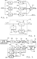
- FIG. 3 there is shown a mathematical model for a generalized parallel configuration of signal generator and adaptive filter pairs which represents signal processing steps programmed into and carried out by the digital signal processor 52 for the second channel of the noise controller 26. It will be recognized that the other channels of noise controller 26 can be programmed to have similar configurations and signal processing steps.
- Each adaptive filter AF j operates on its respective sampled input signal X j (n) to produce a sampled digital filter output signal Y j (n).
- All of the sampled filter output signals Y j (n) from the adaptive filters AF j are directed to a signal summer 211, where they are added together to produce digital samples for the final output noise cancelling signal Y T (R) generated by the digital signal processor 52.
- Each adaptive filter AF j is also provided with digital sample values ER(n) representing the second channel feedback error signal ERROR2 (see Figure 2), so that the characteristics of the J adaptive filters can be adapted to reduce the magnitude of the ERROR2 signal and the corresponding level of residual exhaust noise 22 propagating from the engine 10 (see Figure 1).
- the sampled generator output signal X j (n) produced by the jth signal generator SG j can be easily adjusted to contain sinusoidal components having frequencies at selected even, odd and/or half-order multiples of the fundamental frequency of rotation of the engine f0.
- each of the adaptive filters in Figure 3 will now be described in terms of a general model representing the jth adaptive filter AF j as shown in Figure 4, which is commonly known as the filtered-X least-mean-square (LMS) configuration.
- the components within each adaptive filter AF j include a transversal digital filter A j 212 which filters or transforms the filter input signal, in this case the sampled signal X j (n) synthesized by the jth signal generator SG j , to produce a sampled filter output signal Y j (n) according to the equation: where the set of W ij (n) terms represents the most recently computed adaptive filter weighting coefficients for the transversal filter A j 212, and N j represents the number of taps or size of transversal filter A j , and also the number of samples of the jth signal generator output X j (n) retained in memory for computing the current sample value for the filter output signal Y j (n).
- the transversal filter A j 212 in each adaptive filter AF j can have a different number of taps N j , however, the number of taps for a particular filter should be equal to at least twice the number of sinusoidal signal components selected to be synthesized by that filter's corresponding signal generator SG j so that the transversal filter will be capable of forming a separate passband for each synthesized sinusoidal signal component.
- the weighting coefficients W ij (n) for each transversal filter A j are updated, as indicated by the UPDATE A j block 214, to minimize the value of the sampled error signal ER(n).
- This updating is preferably accomplished using the leaky least-mean-square (LMS) algorithm, although any other known algorithm for adapting filter weighting coefficients to minimize the error signal could be used.
- LMS leaky least-mean-square
- the UPDATE A j block has two inputs, the first being the current sample value for the error signal ER(n), and the second being a filtered sequence of sample values designated as FX j (n), which are derived by passing samples of the filter input signal (here the jth signal generator output X j (n)) through an auxiliary compensation E filter 216.
- This auxiliary filtering process gives rise to the filtered-X nomenclature associated with this type of adaptive filter.
- W ij (n+1) g j W ij (n) - ⁇ j ER(n) FX j (n) , (3)
- g j is known as the filter leakage factor, generally having a value in the range of 0 « g j ⁇ 1
- ⁇ j is known as the filter convergence factor, generally having a value in the range of 0 ⁇ ⁇ j « 1.
- the convergence factor ⁇ j is related to the rate at which the filter output signal samples represented by Y j (n) converge to values which minimize the sampled error signal ER(n).
- the leakage factor g j prevents the accumulation of digital quantization error that typically occurs when using a digital signal processor having fixed point arithmetic capabilities, such as the Motorola 56000 DSP. In applications where the frequency and amplitude of the noise are stationary or slowly varying with respect to time, g j and ⁇ j are conventionally fixed at constant values.
- a compensation filter such as the E filter 216 is typically used to compensate for the delay and distortion introduced by components in the error path of the active noise control (ANC) system.
- This error path typically includes the channel cancellation actuator and the associated output circuitry within noise controller 26; the error sensor and the associated error input circuitry within noise controller 26; and the characteristics of the physical path between the channel cancellation actuator and error sensor, over which the engine noise propagates.
- FIG. 5 there is shown a schematic diagram representing a process which can be used for off-line calibration of each compensation E filter 216.
- the E filter is calibrated (that is, its weighting coefficients are adjusted) to have a transfer function equivalent to the combined electrical components in the error path of the second channel between the the digital signal processor (DSP) digital output signal Y T (n) and digital input error signal ER(n).
- DSP digital signal processor
- the noise cancellation actuator 32 and the error sensor 34 are made to remain at the same locations as when they are used for attenuating noise, to assure that the characteristics of the propagation path between the cancellation actuator 32 and error sensor 34 remain constant.
- a conventional random noise generator 218 is used to generate a sequence of random signal values designated as IN(n).
- the random signal samples are directed as an input to the auxiliary compensation E filter 216, and are also passed through the components of the error path to produce a corresponding sequence of samples designated as D(n).
- the IN(n) samples are subjected to the same electronic components as are output Y T (R) samples and the resulting ER(n) samples of the second channel 46 of the noise controller 26 of Figure 2.
- the weighting coefficients of the digital E filter 216 are adaptively updated to minimize the ERR(n) values.
- the adaptive modelling procedure is complete when the variable weighting coefficients E i (n) sufficiently converge to fixed values. These fixed values then correspond to the fixed weighting coefficients E i used in implementing the E filter 216.
- the transfer function of the digital E filter 216 duplicates that of the combined components in the channel error path and it is used for filtering the sampled X j (n) signal to produce filtered samples for the FX j (n) signal input to the UPDATE A j block 214 in Figure 4. Filtering the samples of the X j (n) signal in this manner compensates for distortion and delay introduced by the error path components and improves the stability and rate of convergence of the adaptive filter AF j .
- the above-described parallel configuration of signal generators SG j and paired adaptive digital filters AF j provides distinct advantages over conventional adaptive filtering approaches, particularly when the difference in frequency between adjacent noise components (that is, those noise components immediately preceding or following each other in the frequency domain) become relatively small.
- the required number of parallel signal generator and adaptive filter pairs in the configuration can be less than the total number of noise frequency components being attenuated, since each signal generator is capable of producing or synthesizing more than one of the sinusoidal signal components corresponding in frequency with the noise components. More importantly, each signal generator in the parallel configuration can be programmed to produce a set of sinusoidal signal components having frequencies corresponding to non-adjacent noise frequency components. This aspect is significant because the difference in frequency between successive sinusoidal signal components filtered by any one adaptive filter is effectively increased, which enables a reduction in the number of filter taps without adversely affecting filtering performance. As will be recognized by those skilled in the art, the filter convergence factor can be enlarged to increase the rate of convergence as the number of filter taps decreases without degrading filter stability.
- FIG. 6 there is shown a block diagram for a model representing signal processing steps programmed into the digital signal processor 52 of the electronic noise controller 26 (see Figure 2) for attenuating engine generated exhaust noise.
- the measured variations in amplitude and frequency of the exhaust noise components with changes in engine speed was considered in conjunction with separating those sinusoidal signal components which correspond to exhaust noise components having adjacent frequencies.
- engine exhaust noise The following predominant characteristics of the engine exhaust noise were identified during the operation of engine 10, which for the present embodiment was a 4.9 litre, 8 cylinder engine: (1) as the engine was operated over its range of possible rotational speeds, the dominant noise components in the exhaust noise (those having significant amplitudes) were found to have the frequencies of mf0/2, where m has integer values ranging from 2 to 16 and f0 is the fundamental frequency of rotation of the engine in Hz (that is, revolutions per second or RPM/60); (2) the exhaust noise component having a frequency of 4f0 was found to have a significant amplitude at rotational speeds between 600 and 2200 RPM; (3) engine noise components having frequencies of f0, 2f0, 3f0, 5f0, 6f0, 7f0 and 8f0 were found to have significant amplitudes when the engine was operated above 1400 RPM; and (4) engine noise components having frequencies of 3f0/2, 5f0/2, 7f0/2, 9f0/2, 11f0/2, 13f0/2 and
- the amplitude and frequency of the exhaust noise components can vary quite rapidly in response to abrupt changes in engine rotational speed during rapid acceleration or deceleration of the engine.
- additional improvements in performance of the active noise control system can be realized by programming each signal generator to synthesize a distinct set of signal components having frequencies corresponding to those noise components that behave in the same manner over a particular range of engine rotational speeds.
- additional improvements in the performance of the active noise control system can be realized by programming each signal generator to synthesize sinusoidal signal components corresponding in frequency with engine noise components having similar amplitude behavior at different engine rotational speeds.
- signal generator SG1 was programmed to synthesize the sinusoidal signal component having a frequency corresponding to a noise component frequency of 4f0. This was done by assigning the value of zero to all B m1 amplitude terms in equation (1) for the SG1 signal generator, except for the B81 amplitude term associated with the sinusoidal signal component having the frequency of 4f0.
- Those amplitude terms B mj corresponding to the frequencies of sinusoidal components that are produced by the signal generators can be assigned values of 1.0 or they can be assigned relative values obtained by averaging the measured amplitudes of the corresponding engine noise frequency components over the range of possible engine rotational speeds.
- the above manner of partitioning not only separates the sinusoidal components so that no one signal generator is required to synthesize any sinusoidal components which correspond to engine noise components having adjacent frequencies but it also enables the implementation of a control strategy, whereby the operation of the configuration of parallel signal generator and adaptive filter pairs can be regulated to compensate for the rapid variations in the amplitude and frequency of engine generated noise components when engine rotational speed changes.
- each signal generator and paired adaptive filter in the parallel configuration is carried out by a filter controller 250 and three signal multipliers 252, 254 and 256, each being interposed between one of the signal generator outputs and the input of the corresponding paired adaptive filter.
- These output control signals are derived in the filter controller 250 based upon information provided by digital COUNT signal.
- control signals S j are fed to the respective signal multipliers 252, 254 and 256 to effect amplitude scaling of each signal generator output signal X j (n), thereby producing a new amplitude scaled input signal S j X j (n) for each adaptive filter AF j .
- the above-described equations (2) and (4) will continue to apply, except that each occurrence of the expression X j (n) will be replaced by its corresponding amplitude scaled counterpart S j X j (n).
- control signals U j and G j are fed directly to each of the respective adaptive filters AF j to modify the updating or adaptation process. This is accomplished by adjusting or scaling the values of the leakage factor g j and convergence factor ⁇ j in the algorithm used to update each adaptive filter, based upon the current values of the control signals U j and G j .
- the values for the control signals S j , U j and G j are determined by filter controller 250 as a function of the engine rotational speed in RPM and/or the engine rotational acceleration expressed in RPM/second (or RPM/s).
- the scaling constants K1 and K2 are selected so that equations (10), (11) and (12) provide the correct values for the engine rotational speed and acceleration for the sampling interval associated with the sampling rate established by the digital signal processor 52.
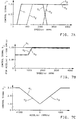
- each control signals S j shown in Figure 7A were selected to correlate with the behaviour of the engine noise frequency components which correspond in frequency with the sinusoidal signal components synthesized by each respective signal generator SG j .
- the engine noise component having a frequency of 4f0 was generally found to have a significant amplitude when the engine was operated at rotational speeds in the range from 600 to 2200 RPM.
- control signal S1 is used to scale the amplitude of the output sinusoidal signal from signal generator SG1, which corresponds to this engine noise component at the frequency of 4f0, S1 is given a value of 1.0 for rotational speeds in the range from 600 to 2200 RPM and a value of zero outside this range, except for narrow transitional bands of a few hundred RPM on either side of the 600-2200 RPM range to prevent S1 from shifting too abruptly between the values of zero and one.
- the values for the control signals S2 and S3 in Figure 7A are selected to follow the behavior of the engine noise components corresponding in frequency with the sinusoidal signal components being synthesized by the signal generators SG2 and SG3, respectively.
- the values of the leakage factor g j used in the least-mean-square (LMS) filter adaptation algorithm determine the degree to which values of the updated filter weighting coefficients W ij (n+1) are influenced by past values of the weighting coefficients W ij (n) determined during the previous sampling interval.
- the larger the value of the leakage factor g j the larger will be the contribution from the past value of a filter weighting coefficient in determining its new updated value and the more prone the filter is to retaining or remembering its past filtering characteristics.
- the adaptive filter leakage factors in the present embodiment are modified by scaling their values in accordance with the control signals G j produced by the filter controller 250.
- all of the control signals G j have values of 1.0.
- the two control signals G2 and G3 are determined as a function of the computed engine SPEED(n) as shown in Figure 7B.
- the value of G1 remains equal to 1.0, since the engine noise component at the frequency 4f0 does not disappear during rapid engine deceleration and, consequently, adaptive filter AF1 must retain a passband at the frequency 4f0.
- adaptive filters AF2 and AF3 By determining the values of G2 and G3 in this fashion and scaling the leakage factors of adaptive filters AF2 and AF3 according to equation (8), it has been found that the adaptive filters can be made to respond more quickly to the disappearance of engine noise components during periods of rapid engine deceleration, thereby significantly enhancing the performance of the active noise control system.
- the engine noise components and hence the sinusoidal signal components synthesized by the signal generators have frequencies which shift in response to variations in engine rotational speeds during abrupt engine acceleration and deceleration.
- each adaptive filter with a variable rather than a fixed convergence factor. Since the rate at which signal component frequencies vary depends directly upon the rate of change of the engine rotational speed, that is the engine rotational acceleration, the values of the filter convergence factors are made to depend upon the magnitude of the engine rotational acceleration. This is accomplished in the embodiment illustrated in Figure 6 by the filter controller 250, which generates control signals U j for scaling the convergence factors of the adaptive filters AF j .
- the control signals U j are given values of 3.0 to provide the adaptive filters with relatively larger convergence factors and increased rates of convergence. As shown, the values of the control signals U j increase linearly from 1.0 to 3.0 as engine acceleration or deceleration increases from zero up to 1000 RPM/s. Scaling of the adaptive filter convergence factors so that they vary in value as a function of engine acceleration in the above-described fashion significantly enhances the ability of each adaptive filter to track frequency fluctuations in filter input signal components caused by variations in engine rotational speed.
- control signals S j , G j and U j in Figure 7A-C were shown to vary as piecewise linear functions of either engine speed or acceleration. It will be recognized that these representations for the control signals were merely exemplary and that other linear or non-linear representations could just as easily be used. It will also be understood that different forms of noise and/or noise generated by different types of engines will generally have characteristics which differ from those described above but the control techniques can still be applied to these applications by selecting the appropriate values for the control signals based upon the principles set forth above.
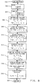
- FIG. 8 there is shown a flow chart representative of the program steps executed by the digital signal processor 52 in performing the parallel signal generating, adaptive filtering and in controlling functions indicated by the block diagram of Figure 6.
- the active noise control (ANC) routine is entered at point 300, after each system interrupt associated with the sampling rate of the digital signal processor 52. It will be understood that prior to the first pass through the ANC routine, the appropriate variables, timers, counters and so on will have been initialized to the proper starting values. From point 300, the program proceeds to step 302, where the values of the input signal COUNT and digitized error signal ER(n) are read.
- step 304 values for the current engine speed SPEED(n) and acceleration ACCEL(n) are computed according to equations (11) and (12) described previously.
- control signals G2 and G3 are less than 1.0 and vary with engine speed as shown in Figure 7B, only when the computed engine acceleration ACCEL(n) ⁇ -1000 RPM/s. Consequently, the control signals G1, G2 and G3 are given the values of 1.0 and the routine reduces these values for G2 and G3 in accordance with SPEED(n) as shown in Figure 7B, only after first determining that the computed ACCEL(n) ⁇ -1000 RPM/s.
- the stored values for each signal generator schedule are determined from equation (1) by summing the appropriate sinusoidal terms selected to be synthesized by each signal generator over the range of different values for COUNT. It will be recalled that the particular sinusoidal signal components synthesized by each signal generator in the present embodiment were selected as described above. After determining a set of values for a particular generator in this fashion, the values are usually normalized to range between -1 and 1 prior to storage in their respective look-up schedule. This is achieved by dividing each value in the set by the magnitude of the value found to be largest in the set.
- step 310 the amplitude of each signal generator output signal is scaled. This is accomplished by multiplying the digital amplitude values produced by each signal generator, represented here as X j (n) OLD , by the value for the corresponding control signal S j determined at step 306. The product S j X j (n) OLD then replaces the previous value for X j (n) stored in memory.
- the leakage and convergence factors g j and ⁇ j employed in the adaptation algorithm of each adaptive filter, are modified by scaling their values according to equations (8) and (9) using the values of the control signals G j and U j found previously at step 306.
- updated values for the weighting coefficients W ij (n+1) for each adaptive filter AF j are computed according to equation (3) using the modified values for the leakage and convergence factors g j and ⁇ j found at step 314 above.
- These updated values for the filter weighting coefficients are the ones which will be used at step 312 during the next pass through the routine (next sampling interval) to compute new values for the digital filter output signals.
- step 316 the routine proceeds to step 318, where the individual values for the filter output signals Y j are summed or added together to produce a digital sample for the final output noise cancelling signal Y T (n).
- step 318 the routine is exited at step 320. It will be understood that the above ANC ROUTINE is repeatedly executed by the digital signal processor 52 after each sampling interrupt to generate successive sample values for the digital noise cancelling signal Y T (R) for output by the digital signal processor 52.
- the ANC ROUTINE implements the particular configuration shown in Figure 6, which comprises three signal generators and their corresponding paired adaptive filters connected in parallel to the signal summer, with the operation of each signal generator and adaptive filter under the direct control of the filter controller.
- the flow chart for the ANC ROUTINE is equally applicable when implementing the general parallel signal generator and paired adaptive filter configuration of Figure 3, which does not include the filter controller or its scaling functions.
- the integer variable j would be allowed to have integer values ranging from 1 to J
- the leakage and convergence factors for each adaptive filter would be assigned fixed values and steps 304, 306, 310 and 314 would be removed from the ANC ROUTINE.
- the filter controller 250 provides three different types of control signals S j , G j and U j to each signal generator and corresponding paired adaptive filter in the parallel configuration shown in Figure 6.
- Each type of control signal performs a separate and distinct function which can provide advantages or benefits different and apart from those provided by the other types of control signals. Consequently, it will be understood that each control function can be implemented either individually or in combination with any of the other control functions in the ANC ROUTINE by simply removing or adding the appropriate scaling operations at steps 310 and 314.
- each adaptive filter in the active noise control system has been the filtered-X configuration, with the adaptation or updating of filter weighting coefficients achieved by use of the leaky least-mean-square algorithm.
- Other types of adaptive filter configurations and updating algorithms are known and used by those skilled in the art of active noise control, and it will be recognized that the principles underlying the above embodiments will be equally applicable to other types of active noise control systems having different adaptive filter configurations and updating algorithms.
- the equivalent leakage and/or convergence factors in any type of filter updating algorithm can be scaled in accordance with changes in engine rotational speed and/or acceleration to improve the adaptive filter response to such changes.
- the amplitude of any input signal representing the engine noise to be cancelled by an active noise control system can be scaled as a function of engine rotational speed to make the input signal more representative of the behaviour of the amplitude of the noise as engine rotational speed changes.
Abstract
Description
- This invention relates to a noise attenuation system, for example to an active noise control (ANC) system used for attenuating undesirable noise produced by an internal combustion engine, where the noise may contain multiple closely spaced sinusoidal frequency components having amplitudes and frequencies varying in relationship with the rotational speed of the engine.
- Conventional active noise control (ANC) systems attenuate undesirable noise by producing and superimposing noise cancelling waves, which are substantially equal in amplitude and frequency content, but shifted 180 degrees in phase with respect to the undesirable noise. As used in the present specification and the appended claims, the term noise is intended to include both acoustic waves and mechanical vibrations propagating from a noise source.
- Recently, active noise control has been accomplished by employing modern digital signal processing and adaptive filtering techniques. Typically, an input sensor is utilized to derive a signal representative of the undesirable noise generated by a source. This signal is then fed to the input of an adaptive filter and is transformed by the filter characteristics into an output signal used for driving a cancellation transducer or actuator such as an acoustic speaker or electromechanical vibrator. The speaker or vibrator produces cancelling waves or vibrations which are superimposed on the undesirable noise generated by the source. The observed or residual noise level resulting from the superposition of the cancelling waves on the undesirable noise is then measured with an error sensor, which develops a corresponding error feedback signal. This feedback signal provides the basis for modifying the characteristics of the adaptive filter to minimize the overall level of the observed or residual noise.
- Such systems have been successfully applied to attenuate, for example, repetitive noise generated by fans or electric motors and random noise propagating down heating and air conditioning ducts. The nature of acoustic and vibrational noise generated by an internal combustion engine differs quite significantly from the nature of the repetitive or random noise encountered in the past.
- Engine generated noise generally contains a large number sinusoidal noise components having amplitudes and frequencies functionally related to the rotational speed of the engine. These frequency components have been found to be the even and odd harmonics of the fundamental frequency of engine rotation (in revolutions per second), as well as half-order multiples or sub-harmonics interposed between the even and odd noise harmonics. Consequently, at low engine speeds, the difference in frequency between adjacent noise components (that is, those noise components immediately preceding or following each other in the frequency domain) can become quite small, for example, as little as 5 Hz at engine idle. In addition, the amplitude, frequency, and phase of the engine generated noise components can vary quite rapidly in response to changes in engine rotational speed brought about by acceleration or deceleration of the engine. Also, engines having differing numbers of cylinders generate noise characterized by different dominant frequency components due to the difference in their firing frequencies. Finally, engine generated noise can have different amplitude and frequency characteristics depending upon the particular type of noise, for example, acoustic noise propagating from the engine intake or exhaust system, or mechanical vibrations produced by operation of the engine, which are transmitted to a vehicle frame.
- The present invention seeks to provide an improved noise attenuation system.
- According to an aspect of the present invention, there is provided a noise attenuation system for attenuating noise generated by an internal combustion engine as specified in
claim 1. - The invention can provide a flexible active noise control system which can be tailored to attenuate effectively undesirable noise containing multiple sinusoidal frequency components, for example in applications where the difference in frequency separating noise components is small in comparison with the values of their individual frequencies and where the amplitude, frequency and phase of the sinusoidal noise components can change quite abruptly, such as in noise generated by an internal combustion engine during periods of rapid engine acceleration or deceleration.
- A preferred embodiment provides an active noise control (ANC) system for attenuating engine generated noise, where the noise contains at least one sinusoidal noise component having an amplitude and frequency which vary in relation to changes in engine rotational speed. The system of this embodiment includes means for generating at least one input signal which contains one or more sinusoidal signals each having a frequency corresponding to that of a respective one of the noise components. Each input signal is filtered by a respective adaptive filter having adjustable filtering characteristics to produce a corresponding filter output signal. Noise cancelling waves are generated by an actuator in response to at least one filter output signal, and the cancelling waves are superimposed with the undesirable noise generated by the engine. The level of residual noise resulting from this superposition is sensed and an error signal indicative of the residual noise level is developed. The response of the ANC system to variations in engine noise is improved by adaptively adjusting the filtering characteristics of at least one adaptive filter to reduce the residual noise level based upon either the error signal and sensed rotational acceleration of the engine, or the error signal and both the sensed rotational speed and acceleration of the engine.
- Preferably, the filtering characteristics of at least one adaptive filter are adaptively adjusted in accordance with an algorithm having a convergence factor and a leakage factor, where the value for the convergence factor is scaled as a function of the sensed rotational acceleration of the engine and/or the value of the leakage factor is scaled as a function of the sensed engine rotational speed and acceleration. Scaling the convergence factor of a filter in this fashion has been found to improve the ability of the system to track and respond to variations in the amplitude and frequency of noise components induced by changes in engine rotational speed. Scaling the leakage factor of an adaptive filter as a function of sensed engine rotational speed and acceleration can enable the system to respond more quickly to the disappearance of engine noise components that occurs when the engine is rapidly decelerated at lower engine rotational speeds.
- When the engine noise contains multiple noise components, it is also preferable that the system includes signal generating means for producing a plurality of generator output signals; a plurality of adaptive filters, each filtering a respective one of the generator output signals to produce a corresponding filter output signal; and summing means for adding all of the filter output signals to obtain a cancelling signal for driving the system noise cancellation actuator. With this configuration, the signal components can be partitioned among the generator output signals according to the amplitude behavior of the corresponding noise components with engine rotational speed changes. By partitioning the signal components in this fashion, the adaptive adjustment of the filtering characteristics of each adaptive filter can be tailored in accordance with the amplitude behaviour of those engine noise components that correspond to the signal components in the generator output signal for the respective adaptive filter to improve the performance of the system.
- The disclosure in the present application may be combined with the disclosures in our two co-pending applications No. (RJ/3767) and No. (RJ/3769) filed the same day as this application.
- An embodiment of the present invention is described below, by way of illustration only, with reference to the accompanying drawings, in which:
- Figure 1 is a schematic diagram of an active noise control system incorporating an embodiment of multi-channel electronic noise controller for attenuating different forms of undesirable noise generated by an engine;
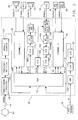
- Figure 2 is a block diagram representative of the electronic components employed in the noise controller shown in Figure 1;
- Figure 3 is a mathematical model containing a parallel configuration of signal generator and adaptive filter pairs representing signal processing steps programmed into and carried out by the digital signal processor of Figure 2 for active noise control;
- Figure 4 is a block diagram representing the modelling components contained within each of adaptive filters AFj of the model shown in Figure 3;
- Figure 5 is a block diagram illustrating an off-line calibration process for a compensation E filter included within each adaptive filter AFj of the model illustrated in Figure 4;
- Figure 6 is a mathematical model programmed into a digital signal processor of the controller, which includes a filter controller for use in conjunction with the parallel configuration of signal generator and adaptive filter pairs employed for attenuating engine generated exhaust noise;
- Figures 7A-C illustrate typical values for control signals produced by the filter controller in the model shown in Figure 6 as a function of the rotational speed and/or acceleration of the engine when cancelling exhaust noise; and
- Figure 8 is a flow chart representative of the steps executed by a routine programmed into the digital signal processor to perform the signal generating, adaptive filtering, and control functions of the mathematical model shown in Figure 6.
- Referring to Figure 1, there is shown schematically an
internal combustion engine 10, with its associatedair intake system 12 andexhaust system 14. Arotatable throttle valve 16 is included within theair intake system 12 for regulating air flow to theengine 10. Also shown are two sensors generally associated with the electronic control of engine performance. The first is a standardthrottle position sensor 18, such as a potentiometer, which is connected tothrottle valve 16 for developing an electrical signal TP related to the degree or percent of throttle valve opening. The second is a conventional engine rotation sensor, in this case shown as atoothed wheel 42 mounted on the engine crankshaft, and anelectromagnetic sensor 44 which produces a SPEED signal having pulses corresponding to the movement of teeth onwheel 42past sensor 44. As shown,toothed wheel 42 has six symmetrically spaced teeth, which produce six equally spaced pulses in the engine SPEED signal for every complete revolution of theengine 10. This particular toothed wheel is merely exemplary, and wheels having different numbers of teeth can just as easily be used or, alternatively, any other known type of sensor or transducer capable of producing outputs pulses in response to the rotation of the engine can be employed. - During the operation of
engine 10, acoustic pressure waves are generated, which propagate away from the engine through the ducts and tubes forming the air intake and exhaust systems. Eventually, these pressure waves propagate from openings in the intake and exhaust systems as observableengine induction noise 20 andexhaust noise 22. In addition, the engine generates undesirable noise in the form ofmechanical vibrations 24, which are transferred to amounting frame 40 used to supportengine 10. - The system includes an active noise controller, the general components of which are shown in Figure 1. For illustrating a few of the many different applications that are possible,
electronic noise controller 26 is shown as a multi-channel device having three separate channels, with each channel operating to attenuate one of the different forms of engine noise discussed above; that is, intake induction noise, exhaust noise and vibrational noise. - One channel of the
noise controller 26 is utilized to attenuate the engine generated induction noise propagating inside theair intake system 12. As will be described, theelectronic noise controller 26 generates a cancelling OUTPUT₁ waveform based upon the input engine SPEED signal. This OUTPUT₁ signal drives a cancellingactuator 28, which in this case is an acoustic speaker, which produces cancelling acoustic waves which are superimposed on the engine generated induction noise. Sensor ortransducer 30, in this case an acoustic microphone, is positioned in theair intake system 12 to measure the level of the residual or attenuated induction noise remaining in theair intake system 12 after the superposition of the cancelling acoustic waves.Sensor 30 develops an ERROR₁ signal representing the level of the residual induction noise, which is fed back to the induction noise channel of theelectronic noise controller 26. This ERROR₁ signal provides the basis for minimizing the observed orresidual induction noise 20 propagating out ofengine intake system 12. - A second channel of the
noise controller 26 is employed to cancel exhaust noise. The operations described above for the induction noise application are duplicated, except that a noise cancelling signal OUTPUT₂ is produced to drive the exhaust noise cancelling actuator 32 (in this case an acoustic speaker) positioned to generate and propagate acoustic waves in the exhaust system, and an error sensor 34 (in this case an acoustic microphone) for developing an ERROR₂ signal representing the level of residual exhaust noise propagating fromengine 10. - Similarly, for cancelling engine generated
vibrational noise 24, a third channel of thenoise controller 26 produces noise cancelling signal OUTPUT₃ to drive anelectromechanical vibrator 36, shown here disposed betweenengine 10 and mountingframe 40.Electromechanical vibrator 36 may be any suitable type which is capable of producing the required out-of-phase cancelling vibrations for superposition with the engine generated vibrations transmitted to mountingframe 40. For example, a commercially available Model LAV 2-3/5-6 actuator manufactured by Aura Inc could be used as shown in Figure 1 or, alternatively, a Model 203B Shaker supplied by Sing Electronics Inc could be mounted onframe 40 for producing the required out-of-phase cancelling vibrations. For this channel, an error feedback signal ERROR₃ representing the residual vibrations transferred to the mountingframe 40 is developed by anerror sensor 38, which in this case is a standard accelerometer attached to the mountingframe 40. - Referring now to Figure 2, the electronic circuitry within the
noise controller 26 will now be described in terms of a block diagram containing standard well known electronic components present in thesecond channel 46 in the noise controller. The first and third channels, 48 and 50 respectively, contain the same components adapted to provide the appropriate input and output levels for their particular cancellation actuators and error sensors and, accordingly, only the components within the second channel will be described. - It will be recognized that the implementation shown in Figure 2 is merely exemplary and other variations in the hardware are possible, as evident in the numerous patents, texts, and publications directed towards active noise control, see for example "Hardware and Software Considerations for Active Noise Control", M. C. Allie, C. D. Bremigan, L. J. Eriksson, and R. A. Greiner, 1988, IEEE, CH 2561-9/88/0000-2598, pp. 2598-2601.
- One of the principal electronic components in the preferred embodiment of
noise controller 26 is a digital signal processor (DSP) designated bynumeral 52. Digital signal processors are commercially available, such as the Motorola 56000, and typically include a central processing unit (CPU) for carrying out instructions and arithmetic operations, random access memory (RAM) for storing data, a programmable read only memory (PROM) for storing program instructions, and clock or timing circuitry used, for example, to establish the data sampling rate at which the digital signal processor operates. For the multiple channel operation illustrated in Figures 1 and 2, thedigital signal processor 52 is programmed to function as one or more adaptive filters for each channel and it operates sequentially to perform the necessary steps or operations for each channel within the established data sampling rate (2.5 KHz in the present embodiment). - As described above, an indication of the angular rotational position of the engine is preferably provided to the
electronic noise controller 26 by the SPEED signal developed by theelectromagnetic speed sensor 44. The SPEED signal contains pulses generated by the movement oftoothed wheel 42 pastelectromagnetic sensor 44. After entering thenoise controller 26, the SPEED signal is passed tostandard conditioning circuitry 146, where the pulses are shaped or squared up into a format compatible with the digital circuitry that follows. These formatted digital pulses represent a measure of the angular rotation of the crankshaft and are passed to a standard frequency multiplier/divider circuit 148 which generates a fixed or predetermined number of pulses during one complete rotational cycle of the engine. The pulses from the frequency multiplier/divider 148 are then counted by a conventional modulocounter 150 to provide a digital output signal designated as COUNT. This digital COUNT signal is then used as a reference input signal to thedigital signal processor 52 representing the time-varying degree of engine rotation through a complete engine cycle. As such, it will be recognized that the value of the COUNT signal will be functionally related to the frequencies of sinusoidal noise components generated by the engine. - In general, the number of teeth on
wheel 42, the frequency multiplier/divider, and the modulo counter are selected to provide an integer count ranging in value from 0 to a maximum value of MAX each time the engine completes a cycle, a complete cycle in a four-stroke engine being two full revolutions of the engine crankshaft. The value of COUNT then represents the time-varying angular rotational position of the engine in an operating cycle or the fractional portion of an engine cycle completed at any given time (the cycle position). Based upon the value of the COUNT reference input signal, thedigital signal processor 52 is able to generate signals containing different sinusoidal components having frequencies which correspond to those of the sinusoidal noise components generated by the engine. - In addition to the SPEED signal, the other analogue signals directed to the
noise controller 26 are sampled at the rate established bydigital signal processor 52 and digitized for further use within thedigital signal processor 52. Sets of sample values for the digitized input signals are retained in the random access memory ofdigital signal processor 52 for use in computing sample values for digital output signals in accordance with the programmed adaptive filters in each channel. The computed digital output signal samples fromdigital signal processor 52 are then converted into analogue form and appropriately amplified to drive the channel cancellation actuators. - With regard to analogue input signals directed to the
electronic noise controller 26, the analogue throttle position signal TP fromsensor 18 is first passed throughamplifier 152 and then converted into a digital input signal TP(n) for thedigital signal processor 52 by the action of sample and holdcircuit 154 and analogue-to-digital converter 156. TP(n) then represents the nth or most recent digitized sample value for the analogue throttle position signal TP, TP(n-1) represents the digitized sample value for TP obtained during the previous sampling period and, likewise, for earlier sample values of the throttle position signal. - Although not required in this embodiment, the digitized throttle position signal TP is shown as an input to the
digital signal processor 52 for completeness, since it provides an indication of engine loading and may be used to improve the performance of the noise controller, as described in EP-A-0,470,656, the disclosure in which is incorporated herein by reference. - The analogue ERROR₂ signal developed by
microphone sensor 34 is first amplified by avariable gain amplifier 158 and then passed through abandpass filter 160 having, for example, a passband from approximately 20 to 700 Hz in this embodiment.Bandpass filter 160 acts as an anti-aliasing filter and removes any direct current from the amplified ERROR₂ signal. The filtered ERROR₂ signal is then fed to sample and holdcircuit 162, which acts in conjunction with analogue-to-digital converter 164 to provide a digitized sample ER(n) of the analogue ERROR₂ signal to thedigital signal processor 52, where, as stated previously, n represents the nth or most recently sampled value. - Based upon the value of the digitized ER(n) sample, the
digital signal processor 52 supplies a digital GAIN signal to digital-to-analogue converter 166, which in turn controls the gain ofamplifier 158 to maintain the amplitude of the amplified analogue ERROR₂ signal within upper and lower limits determined by the input capability of sample and holdcircuit 162 and analogue-to-digital converter 164. This form of automatic gain control is well known in the art and is commonly used in digital signal processor and microprocessor interfacing circuitry when digitizing an analogue signal having an amplitude which can vary over a large dynamic range, such as the ERROR2 signal in the present embodiment. - Sequential digital sample values for an output noise cancelling signal ..., YT(n-2), YT(n-1), and YT(n) are computed by the
digital signal processor 52 in accordance with the above described input signals and the characteristics of the adaptive filters programmed into thedigital signal processor 52 for the second channel. These digital output samples are directed to digital-to-analogue converter 168, where a corresponding analogue waveform is produced. The analogue waveform is then passed throughlowpass filter 170, which has an upper cutoff frequency of approximately 700 Hz in this embodiment. The lowpass filter acts as a smoothing filter to remove any high frequency components introduced by the digital-to-analogue conversion process. Next, the filtered analogue waveform is amplified bypower amplifier 172 to produce the final output noise cancelling waveform designated as OUTPUT₂. The OUTPUT₂ signal drives the cancellation actuator (speaker) 32 to produce the noise cancelling waves which are superimposed with and attenuate the undesirable engine exhaust noise. - Depending upon the amplitude of the noise being attenuated, it may be desirable to prevent the amplitude of the noise cancelling waveform from becoming saturated or clipped at an upper limit related to the physical size of the cancellation actuator. An approach which may be used to prevent such clipping or saturation of the output noise cancelling waveform is described in EP-A-0,492,680 and EP-A-0,470,656, the disclosures in which are incorporated herein by reference.
- Referring now to Figure 3, there is shown a mathematical model for a generalized parallel configuration of signal generator and adaptive filter pairs which represents signal processing steps programmed into and carried out by the
digital signal processor 52 for the second channel of thenoise controller 26. It will be recognized that the other channels ofnoise controller 26 can be programmed to have similar configurations and signal processing steps. - In general, the parallel configuration of Figure 3 is shown to include a total of J signal generators SG₁, SG₂,... and SGJ, designated by the
respective numerals signal summer 211, where they are added together to produce digital samples for the final output noise cancelling signal YT(R) generated by thedigital signal processor 52. Each adaptive filter AFj is also provided with digital sample values ER(n) representing the second channel feedback error signal ERROR₂ (see Figure 2), so that the characteristics of the J adaptive filters can be adapted to reduce the magnitude of the ERROR₂ signal and the corresponding level ofresidual exhaust noise 22 propagating from the engine 10 (see Figure 1). - The operation of each of the signal generators will now be described in terms of a jth signal generator SGj, where j can have the values of j = 1, 2,... or J. In general, the jth generator SGj produces a value for its sampled output signal Xj(n) based on the current value of the COUNT reference input signal in accordance with the following equation:

where the Bmj term represents the amplitude of the mth sinusoidal signal component in a summation that can contain a total of M such components, and q is a conversion constant given by
modulo counter 150, before it resets to zero to restart counting. It will be recognized that one or more sinusoidal signal components can be removed from the above summation by setting their respective amplitudes to zero, that is the mth sinusoidal component can be removed from the signal Xj(n) produced by the jth signal generator SGj by merely setting Bmj = 0 to eliminate any contribution from that component. - It will also be recognized that since COUNT ranges in value from 0 to MAX for each complete engine cycle (two revolutions in a four stroke engine), the frequencies of the sinusoidal components in above equation (1) will be functionally related to and synchronized with the rotational frequency of the engine (in revolutions per second). For example, if the engine rotates at a frequency of f₀ revolutions per second (engine RPM/60), then the frequency of the mth sinusoidal component in the summation of equation (1) is given by

- In what follows, it will be understood that when a set of sequential sample values for a digitized signal, such as the output signal for the jth signal generator Xj(n-Nj+1),..., Xj(n-2), Xj(n-1) and Xj(n), are retained in the random access memory of the
digital signal processor 52 prior to storing a newly generated sample value in the memory location corresponding to the nth sample value Xj(n), the previous stored value for Xj(n) will be shifted downwardly and stored as the next earlier sample value Xj(n-1) and, likewise, for all earlier sample values down to the last retained sample in the sequence Xj(n-Nj+1). - The preferred form for each of the adaptive filters in Figure 3 will now be described in terms of a general model representing the jth adaptive filter AFj as shown in Figure 4, which is commonly known as the filtered-X least-mean-square (LMS) configuration. The components within each adaptive filter AFj include a transversal
digital filter A j 212 which filters or transforms the filter input signal, in this case the sampled signal Xj(n) synthesized by the jth signal generator SGj, to produce a sampled filter output signal Yj(n) according to the equation:
where the set of Wij(n) terms represents the most recently computed adaptive filter weighting coefficients for thetransversal filter A j 212, and Nj represents the number of taps or size of transversal filter Aj, and also the number of samples of the jth signal generator output Xj(n) retained in memory for computing the current sample value for the filter output signal Yj(n). In general, thetransversal filter A j 212 in each adaptive filter AFj can have a different number of taps Nj, however, the number of taps for a particular filter should be equal to at least twice the number of sinusoidal signal components selected to be synthesized by that filter's corresponding signal generator SGj so that the transversal filter will be capable of forming a separate passband for each synthesized sinusoidal signal component. - After each new sample value for the filter output signal Yj(n) is computed according to equation (2), the weighting coefficients Wij(n) for each transversal filter Aj are updated, as indicated by the UPDATE Aj block 214, to minimize the value of the sampled error signal ER(n). This updating is preferably accomplished using the leaky least-mean-square (LMS) algorithm, although any other known algorithm for adapting filter weighting coefficients to minimize the error signal could be used. The UPDATE Aj block has two inputs, the first being the current sample value for the error signal ER(n), and the second being a filtered sequence of sample values designated as FXj(n), which are derived by passing samples of the filter input signal (here the jth signal generator output Xj(n)) through an auxiliary
compensation E filter 216. This auxiliary filtering process gives rise to the filtered-X nomenclature associated with this type of adaptive filter. - The preferred leaky LMS algorithm for updating each of the filter weighting coefficients from the present value Wij(n) to the value Wij(n+1) for use during the next sampling interval is given by:

where gj is known as the filter leakage factor, generally having a value in the range of 0 « gj < 1, and µj is known as the filter convergence factor, generally having a value in the range of 0 < µj « 1. The convergence factor µj is related to the rate at which the filter output signal samples represented by Yj(n) converge to values which minimize the sampled error signal ER(n). The leakage factor gj prevents the accumulation of digital quantization error that typically occurs when using a digital signal processor having fixed point arithmetic capabilities, such as the Motorola 56000 DSP. In applications where the frequency and amplitude of the noise are stationary or slowly varying with respect to time, gj and µj are conventionally fixed at constant values. - The sequence of sample values for the FXj(n) signal required by equation (4) are obtained by filtering the sequence of sample output values Xj(n) from the jth signal generator SGj with an auxiliary
compensation E filter 216 according to the following equation:
where the E, terms for i = 0, 1,..., and NE-1 represents the fixed weighting coefficients for the transversalcompensation E filter 216, with NE representing the number of E filter taps. As described in "An Analysis of Multiple Correlation Cancellation Loops with a Filter in the Auxiliary Path", D. R. Morgan, IEEE Transactions on Acoustic Speech Signal Processing, Vol. ASSP-28, No. 4, 1980, pp.454-467, a compensation filter such as theE filter 216 is typically used to compensate for the delay and distortion introduced by components in the error path of the active noise control (ANC) system. This error path typically includes the channel cancellation actuator and the associated output circuitry withinnoise controller 26; the error sensor and the associated error input circuitry withinnoise controller 26; and the characteristics of the physical path between the channel cancellation actuator and error sensor, over which the engine noise propagates. - Referring now to Figure 5, there is shown a schematic diagram representing a process which can be used for off-line calibration of each
compensation E filter 216. In this process, the E filter is calibrated (that is, its weighting coefficients are adjusted) to have a transfer function equivalent to the combined electrical components in the error path of the second channel between the the digital signal processor (DSP) digital output signal YT(n) and digital input error signal ER(n). When calibrating the E filter, thenoise cancellation actuator 32 and theerror sensor 34 are made to remain at the same locations as when they are used for attenuating noise, to assure that the characteristics of the propagation path between thecancellation actuator 32 anderror sensor 34 remain constant. - During the calibration process, a conventional
random noise generator 218 is used to generate a sequence of random signal values designated as IN(n). The random signal samples are directed as an input to the auxiliarycompensation E filter 216, and are also passed through the components of the error path to produce a corresponding sequence of samples designated as D(n). In passing over the error path, the IN(n) samples are subjected to the same electronic components as are output YT(R) samples and the resulting ER(n) samples of thesecond channel 46 of thenoise controller 26 of Figure 2. - For the calibration configuration shown in Figure 5, the expression associated with operation of the digital
compensation E filter 216 and the algorithm associated with its UPDATEE adaptation block 220 are given by:

where gE and µE are set at approximately gE = 0.99998 and µE = 0.001, OUT(n) represents sample values output by thedigital E filter 216, and the ERR(n) samples are produced as output fromsignal summer 222 and are given by:

where D(n) represents the sample values derived from thechannel error sensor 34. With this off-line calibration process, the weighting coefficients of thedigital E filter 216 are adaptively updated to minimize the ERR(n) values. The adaptive modelling procedure is complete when the variable weighting coefficients Ei(n) sufficiently converge to fixed values. These fixed values then correspond to the fixed weighting coefficients Ei used in implementing theE filter 216. When the adaptive modelling procedure is complete, the transfer function of thedigital E filter 216 duplicates that of the combined components in the channel error path and it is used for filtering the sampled Xj(n) signal to produce filtered samples for the FXj(n) signal input to the UPDATE Aj block 214 in Figure 4. Filtering the samples of the Xj(n) signal in this manner compensates for distortion and delay introduced by the error path components and improves the stability and rate of convergence of the adaptive filter AFj. - As indicated in Figure 4, the
same E filter 216 is preferably used with each adaptive filter AFj, with j= 1, 2,...J, since it provides a broad band characterization of the error path over a range in frequency which embraces the expected variations in frequency of the engine noise components. Also, use of the same compensation E filter for each adaptive filter AFj provides advantages in that the implementation is simplified and RAM storage space is conserved; however, different E filters could be used with each adaptive filter if desirable or advantageous for the particular application. - When employed in active noise control (ANC) systems, the above-described parallel configuration of signal generators SGj and paired adaptive digital filters AFj provides distinct advantages over conventional adaptive filtering approaches, particularly when the difference in frequency between adjacent noise components (that is, those noise components immediately preceding or following each other in the frequency domain) become relatively small.
- First, the required number of parallel signal generator and adaptive filter pairs in the configuration can be less than the total number of noise frequency components being attenuated, since each signal generator is capable of producing or synthesizing more than one of the sinusoidal signal components corresponding in frequency with the noise components. More importantly, each signal generator in the parallel configuration can be programmed to produce a set of sinusoidal signal components having frequencies corresponding to non-adjacent noise frequency components. This aspect is significant because the difference in frequency between successive sinusoidal signal components filtered by any one adaptive filter is effectively increased, which enables a reduction in the number of filter taps without adversely affecting filtering performance. As will be recognized by those skilled in the art, the filter convergence factor can be enlarged to increase the rate of convergence as the number of filter taps decreases without degrading filter stability. Also, as the number of filter taps is reduced, quantities known as the LMS algorithm excess means square error and computational round off error decrease to improve filter accuracy. Consequently, significant improvements in the filter accuracy and the rate of response to fluctuation in noise amplitude, frequency and phase can be realized by employing the above-described parallel configuration of signal generators and correspondingly paired adaptive filters in active noise control (ANC) systems in the above-described manner.
- Referring now to Figure 6, there is shown a block diagram for a model representing signal processing steps programmed into the
digital signal processor 52 of the electronic noise controller 26 (see Figure 2) for attenuating engine generated exhaust noise. The model includes a filter controller, which operates in conjunction with the above described configuration of parallel signal generator and adaptive filter pairs. For this particular application and type of noise, it has been found that three parallel signal generator and adaptive filter pairs (that is, J = 3) are sufficient to achieve an acceptable degree of attenuation of the engine exhaust noise. It has also been found that each transversal filter Aj and each compensation filter E provides satisfactory performance with sixty-four taps, that is Nj = NE = 64; however, it will be understood that a larger or smaller number of filter taps could be used for any of the filters depending upon the required degree of noise attenuation and any limitations on the amount of memory available for storage in thedigital signal processor 52. - In selecting the frequency make-up of the set of sinusoidal signal components synthesized by any one signal generator, the measured variations in amplitude and frequency of the exhaust noise components with changes in engine speed was considered in conjunction with separating those sinusoidal signal components which correspond to exhaust noise components having adjacent frequencies.
- The following predominant characteristics of the engine exhaust noise were identified during the operation of
engine 10, which for the present embodiment was a 4.9 litre, 8 cylinder engine: (1) as the engine was operated over its range of possible rotational speeds, the dominant noise components in the exhaust noise (those having significant amplitudes) were found to have the frequencies of mf₀/2, where m has integer values ranging from 2 to 16 and f₀ is the fundamental frequency of rotation of the engine in Hz (that is, revolutions per second or RPM/60); (2) the exhaust noise component having a frequency of 4f₀ was found to have a significant amplitude at rotational speeds between 600 and 2200 RPM; (3) engine noise components having frequencies of f₀, 2f₀, 3f₀, 5f₀, 6f₀, 7f₀ and 8f₀ were found to have significant amplitudes when the engine was operated above 1400 RPM; and (4) engine noise components having frequencies of 3f₀/2, 5f₀/2, 7f₀/2, 9f₀/2, 11f₀/2, 13f₀/2 and 15f₀/2 were found to have significant amplitudes when the engine was operated above 2500 RPM. - In addition to identifying the above characteristics, it was also found that the amplitude and frequency of the exhaust noise components can vary quite rapidly in response to abrupt changes in engine rotational speed during rapid acceleration or deceleration of the engine. As is explained below, additional improvements in performance of the active noise control system can be realized by programming each signal generator to synthesize a distinct set of signal components having frequencies corresponding to those noise components that behave in the same manner over a particular range of engine rotational speeds. As will be explained, additional improvements in the performance of the active noise control system can be realized by programming each signal generator to synthesize sinusoidal signal components corresponding in frequency with engine noise components having similar amplitude behavior at different engine rotational speeds.
- In the block diagram model illustrated in Figure 6, signal generator SG₁ was programmed to synthesize the sinusoidal signal component having a frequency corresponding to a noise component frequency of 4f₀. This was done by assigning the value of zero to all Bm1 amplitude terms in equation (1) for the SG₁ signal generator, except for the B₈₁ amplitude term associated with the sinusoidal signal component having the frequency of 4f₀.
- The signal generator SG₂ was programmed to synthesize sinusoidal signal components corresponding to engine noise components having the non-adjacent frequencies of f₀, 2f₀, 3f₀, 5f₀, 6f₀, 7f₀ and 8f₀ that were found to have significant amplitudes when the
engine 10 was operated above 1400 RPM. This was accomplished by assigning values of zero to those amplitude terms Bm2 corresponding to frequencies not produced by the second signal generator SG₂, that is Bm2 = 0 for m = 1, 3, 5, 7, 8, 9, 11, 13 and 15. - The third signal generator SG₃ was programmed to synthesize sinusoidal signal components corresponding to engine noise components having the non-adjacent frequencies of 3f₀/2, 5f₀/2, 7f₀/2, 9f₀/2, 11f₀/2, 13f₀/2 and 15f₀/2 that were found to have significant amplitudes when the engine was operated above 2500 RPM. Again, this was accomplished by assigning values of zero to those amplitude terms Bm3 corresponding to those frequencies not produced by the third signal generator SG₃, that is Bm3 = 0 for m = 2, 4, 6, 8, 10, 12, 14 and 16.
- Those amplitude terms Bmj corresponding to the frequencies of sinusoidal components that are produced by the signal generators can be assigned values of 1.0 or they can be assigned relative values obtained by averaging the measured amplitudes of the corresponding engine noise frequency components over the range of possible engine rotational speeds.
- The above manner of partitioning not only separates the sinusoidal components so that no one signal generator is required to synthesize any sinusoidal components which correspond to engine noise components having adjacent frequencies but it also enables the implementation of a control strategy, whereby the operation of the configuration of parallel signal generator and adaptive filter pairs can be regulated to compensate for the rapid variations in the amplitude and frequency of engine generated noise components when engine rotational speed changes.
- As indicated in Figure 6, the control of each signal generator and paired adaptive filter in the parallel configuration is carried out by a
filter controller 250 and threesignal multipliers filter controller 250 develops sets of digital values for the output control signals Sj, Uj and Gj which are directed to control the operation of each signal generator SGj and corresponding paired adaptive filter AFj (where j = 1, 2 and 3). These output control signals are derived in thefilter controller 250 based upon information provided by digital COUNT signal. - The control signals Sj are fed to the
respective signal multipliers - The control signals Uj and Gj are fed directly to each of the respective adaptive filters AFj to modify the updating or adaptation process. This is accomplished by adjusting or scaling the values of the leakage factor gj and convergence factor µj in the algorithm used to update each adaptive filter, based upon the current values of the control signals Uj and Gj. Consequently, the leakage and convergence factors are allowed to have variable values according to the following expressions:


where g₀ and µ0j are set at constant values and the control signals Gj and Uj effectuate a scaling of these constant values to provide the scaled filter adaptation factors gj and µj. For example, g₀ = 0.99998, µ₀₁ = 0.001 and µ₀₂ = µ₀₃ = 0.01, provided stable filter operation in the present embodiment, but it will be recognized that the values selected for the µ0j terms will differ for different applications depending upon factors such as the average power contained in the filter input signals, the number of adaptive filter taps and the electrical characteristics of hardware components such as the actuators and transducers outside the digital signal processor. - The values for the control signals Sj, Uj and Gj are determined by
filter controller 250 as a function of the engine rotational speed in RPM and/or the engine rotational acceleration expressed in RPM/second (or RPM/s). Engine rotational speed for the current sampling interval can be computed byfilter controller 250 using the expression:

where K1 is a scaling constant, COUNT represents the value of themodulo counter 150 during the current sampling interval and COUNT₋₁ represents the stored value of the modulo counter during the previous sampling interval. Although equation (10) provides an acceptable estimate for the actual engine rotational speed, it has been found that a more accurate representation is obtained by averaging a few of the most recently computed sample values for SP(n). Consequently, the preferred expression for computing engine rotational speed for the current or nth sampling interval is given by:
where N represents the number of samples of SP(n) which are averaged, for example, N = 32 in the present embodiment. The rotational acceleration of the engine for the current sampling interval is computed by use of the expression:

where K2 represents an additional scaling constant, SPEED(n) represents the rotational speed of the engine for the current sampling interval computed in accordance with equation (10) and SPEED(n-1) represents the stored rotational speed of the engine found during the previous sampling interval. It will be recognized that the scaling constants K1 and K2 are selected so that equations (10), (11) and (12) provide the correct values for the engine rotational speed and acceleration for the sampling interval associated with the sampling rate established by thedigital signal processor 52. - Referring now to Figures 7(A)-(C), values for the output control signals Sj, Uj and Gj provided by
filter controller 250 are illustrated in graphical form as a function of the computed engine SPEED(n) and/or ACCEL(n), with j = 1, 2 and 3 as used in the present embodiment. - The values for each control signals Sj shown in Figure 7A were selected to correlate with the behaviour of the engine noise frequency components which correspond in frequency with the sinusoidal signal components synthesized by each respective signal generator SGj. For example, the engine noise component having a frequency of 4f₀ was generally found to have a significant amplitude when the engine was operated at rotational speeds in the range from 600 to 2200 RPM. Since the control signal S₁ is used to scale the amplitude of the output sinusoidal signal from signal generator SG₁, which corresponds to this engine noise component at the frequency of 4f₀, S₁ is given a value of 1.0 for rotational speeds in the range from 600 to 2200 RPM and a value of zero outside this range, except for narrow transitional bands of a few hundred RPM on either side of the 600-2200 RPM range to prevent S₁ from shifting too abruptly between the values of zero and one. Likewise, the values for the control signals S₂ and S₃ in Figure 7A are selected to follow the behavior of the engine noise components corresponding in frequency with the sinusoidal signal components being synthesized by the signal generators SG2 and SG3, respectively.
- This amplitude scaling of the output signals synthesized by the signal generators based upon the rotational speed of the engine was found to improve significantly the ability of the active noise control system to attenuate engine noise components having substantial changes in amplitude with variations in engine rotational speed. This is because the scaled amplitudes of the synthesized sinusoidal signal components entering the adaptive filters from the signal generators now more closely match the amplitude behavior of the actual noise components generated by the engine as it operates at different rotational speeds. As a consequence, the adaptive filters require less time to converge or adapt the filter output signals to achieve a satisfactory attenuation of the engine generated noise.
- When
engine 10 is operating at rotational speeds above 1200 RPM and the engine rotation is rapidly decelerated at rates ≧ 1000 RPM/second to speeds below 1200 RPM (for example, during closed throttle, heavy vehicle braking), it has been found that the amplitudes of engine noise components having frequencies other than 4f₀ approach zero very rapidly (in less than one second). Conventional adaptive filters can not respond quickly enough to remove the filter passbands corresponding to these frequencies and the filter output signals Y₂(n) and Y₃(n) will contain signal components having significant amplitudes at these passband frequencies. This will occur even if the actual input signals directed to adaptive filters AF₁ and AF₂ are scaled to zero by control signals S₁ and S₂ as described above, due to the existence of noise which passes through the adaptive filters at the passband frequencies. As a result, the observednoise level 22 will actually increase due to the presence of these unnecessary signal components in the cancelling waves, since the corresponding engine noise components will have disappeared. - It was recognized that the values of the leakage factor gj used in the least-mean-square (LMS) filter adaptation algorithm (see equation (3)) determine the degree to which values of the updated filter weighting coefficients Wij(n+1) are influenced by past values of the weighting coefficients Wij(n) determined during the previous sampling interval. The larger the value of the leakage factor gj, the larger will be the contribution from the past value of a filter weighting coefficient in determining its new updated value and the more prone the filter is to retaining or remembering its past filtering characteristics. Consequently, by decreasing the leakage factor of adaptive filters AF₂ and AF₃ during periods of rapid engine deceleration where engine rotational speed drops below 1200 RPM, it was found that the filter passbands associated with the disappearing engine noise components can be eliminated more quickly during the adaptation process.
- As indicated in equation (8) and Figure 6, the adaptive filter leakage factors in the present embodiment are modified by scaling their values in accordance with the control signals Gj produced by the
filter controller 250. During normal engine operation, all of the control signals Gj have values of 1.0. However, whenfilter controller 250 computes an ACCEL(n) ≦ -1000 RPM/s, the two control signals G₂ and G₃ are determined as a function of the computed engine SPEED(n) as shown in Figure 7B. The value of G₁ remains equal to 1.0, since the engine noise component at the frequency 4f₀ does not disappear during rapid engine deceleration and, consequently, adaptive filter AF₁ must retain a passband at the frequency 4f₀. By determining the values of G₂ and G₃ in this fashion and scaling the leakage factors of adaptive filters AF₂ and AF₃ according to equation (8), it has been found that the adaptive filters can be made to respond more quickly to the disappearance of engine noise components during periods of rapid engine deceleration, thereby significantly enhancing the performance of the active noise control system. - It will also be recognized that the above approach can easily be adapted to scale adaptive filter leakage factors in situations where engine noise components are found to disappear quickly with rapid engine acceleration rather than deceleration, as described above.
- In addition to the above-described amplitude fluctuations the engine noise components and hence the sinusoidal signal components synthesized by the signal generators, have frequencies which shift in response to variations in engine rotational speeds during abrupt engine acceleration and deceleration. Conventional adaptive filters having fixed convergence factors will not generally be able accurately to track filter input signal components which have rapid frequency fluctuations. This is because filter convergence factors are conventionally fixed at relatively small values, for example µ = 0.01, to reduce the magnitude of system residual error (the residual noise level represented by the error signal ER(n) in the present embodiment). If the filter convergence factor is increased, for example to µ = 0.03, the ability of the adaptive filter to track rapid fluctuations in the frequency of components in the filter input signal will be enhanced but the magnitude of the system residual error will increase for constant engine speed operation.
- It was recognized that the above difficulties could be overcome by providing each adaptive filter with a variable rather than a fixed convergence factor. Since the rate at which signal component frequencies vary depends directly upon the rate of change of the engine rotational speed, that is the engine rotational acceleration, the values of the filter convergence factors are made to depend upon the magnitude of the engine rotational acceleration. This is accomplished in the embodiment illustrated in Figure 6 by the
filter controller 250, which generates control signals Uj for scaling the convergence factors of the adaptive filters AFj. - Referring now to Figure 7C, values for the control signals U₁, U₂ and U₃ are illustrated in graphical form as a function of the engine acceleration ACCEL(n) computed by the
filter controller 250 based upon equation (12). For the present embodiment, all of the Uj control signals were made to vary in the same way with changes in ACCEL(n), however, it will be understood that the control signal for each adaptive filter can be made to vary differently with changing engine acceleration and that the values presented in Figure 7C are merely exemplary for the chosen exhaust noise application. - When the engine operates at constant rotational speeds (ACCEL(n) = 0), the frequencies of the engine noise components remain stationary, so it is generally more important to assure that system residual error is a small as possible, rather than to achieve a rapid rate of filter convergence. On the other hand, when the engine is accelerating or decelerating, the frequencies of the engine noise components change rapidly and it is more important to assure that the filter has a rapid rate of convergence.
- It will be noted from equation (9) that the adaptive filter convergence factors in the present embodiment are given by µj = Uj µ0j, where the control signals Uj effect a scaling of the corresponding fixed values for µ0j, which in the present embodiment are given by µ₀₁ = 0.001 and µ₀₂ = µ₀₃ = 0.01. In view of the foregoing, the Uj control signals are given values of 1.0 (see Figure 7C) to provide the adaptive filters with relatively small values for the convergence factors when the rotational speed of the engine is stationary (ACCEL(n) = 0). For rapid engine acceleration or deceleration where ACCEL(n) ≧ 1000 RPM/s or ACCEL(n) ≦ -1000 RPM/s, the control signals Uj are given values of 3.0 to provide the adaptive filters with relatively larger convergence factors and increased rates of convergence. As shown, the values of the control signals Uj increase linearly from 1.0 to 3.0 as engine acceleration or deceleration increases from zero up to 1000 RPM/s. Scaling of the adaptive filter convergence factors so that they vary in value as a function of engine acceleration in the above-described fashion significantly enhances the ability of each adaptive filter to track frequency fluctuations in filter input signal components caused by variations in engine rotational speed.
- The control signals Sj, Gj and Uj in Figure 7A-C were shown to vary as piecewise linear functions of either engine speed or acceleration. It will be recognized that these representations for the control signals were merely exemplary and that other linear or non-linear representations could just as easily be used. It will also be understood that different forms of noise and/or noise generated by different types of engines will generally have characteristics which differ from those described above but the control techniques can still be applied to these applications by selecting the appropriate values for the control signals based upon the principles set forth above.
- Referring now to Figure 8, there is shown a flow chart representative of the program steps executed by the
digital signal processor 52 in performing the parallel signal generating, adaptive filtering and in controlling functions indicated by the block diagram of Figure 6. The active noise control (ANC) routine is entered atpoint 300, after each system interrupt associated with the sampling rate of thedigital signal processor 52. It will be understood that prior to the first pass through the ANC routine, the appropriate variables, timers, counters and so on will have been initialized to the proper starting values. Frompoint 300, the program proceeds to step 302, where the values of the input signal COUNT and digitized error signal ER(n) are read. - Next, at
step 304, values for the current engine speed SPEED(n) and acceleration ACCEL(n) are computed according to equations (11) and (12) described previously. - The routine then proceeds to step 306 where values for the control signals Sj, Gj and Uj for j = 1, 2 and 3 are determined based upon the computed values for the engine speed SPEED(n) and/or acceleration ACCEL(n) found at
step 304. This is accomplished either by computing values for the control signals based upon stored sets of coefficients for empirical equations representing the piecewise linear functional relationships shown in Figure 7A-C or by providing stored look-up tables containing values for the control signals based upon engine speed and/or acceleration, as indicated in Figure 7A-C. It will be noted that the values of the control signals G₂ and G₃ are less than 1.0 and vary with engine speed as shown in Figure 7B, only when the computed engine acceleration ACCEL(n) ≦ -1000 RPM/s. Consequently, the control signals G₁, G₂ and G₃ are given the values of 1.0 and the routine reduces these values for G₂ and G₃ in accordance with SPEED(n) as shown in Figure 7B, only after first determining that the computed ACCEL(n) ≦ -1000 RPM/s. - Once the appropriate values for the control signals are either computed or looked up at
step 306, the routine proceeds to step 308 where the sampled amplitude value Xj(n) for each generator output signal (j = 1, 2 and 3) is derived (or looked up) in a respective predetermined schedule of stored values based upon the current value of the reference input signal COUNT found previously atstep 302. - The stored values for each signal generator schedule are determined from equation (1) by summing the appropriate sinusoidal terms selected to be synthesized by each signal generator over the range of different values for COUNT. It will be recalled that the particular sinusoidal signal components synthesized by each signal generator in the present embodiment were selected as described above. After determining a set of values for a particular generator in this fashion, the values are usually normalized to range between -1 and 1 prior to storage in their respective look-up schedule. This is achieved by dividing each value in the set by the magnitude of the value found to be largest in the set.
- After completing
step 308, the routine passes to step 310 where the amplitude of each signal generator output signal is scaled. This is accomplished by multiplying the digital amplitude values produced by each signal generator, represented here as Xj(n)OLD, by the value for the corresponding control signal Sj determined atstep 306. The product Sj Xj(n)OLD then replaces the previous value for Xj(n) stored in memory. - Next, at
step 312, the filtered output signal Yj(n) for each adaptive filter AFj (j = 1, 2, and 3) is computed according to equation (2), with the filter input signal being the sequence of digital values stored in the designated memory locations for jth signal generator output Xj(n-i), where in the present embodiment i = 0, 1, ... 63, since the adaptive filters have sixty-four taps. Note that each value in the stored sequence represented by Xj(n-i) will have been amplitude-scaled due to step 310. - At
step 314, the leakage and convergence factors gj and µj, employed in the adaptation algorithm of each adaptive filter, are modified by scaling their values according to equations (8) and (9) using the values of the control signals Gj and Uj found previously atstep 306. - Then, at
step 316, updated values for the weighting coefficients Wij(n+1) for each adaptive filter AFj (for j = 1, 2 and 3) are computed according to equation (3) using the modified values for the leakage and convergence factors gj and µj found atstep 314 above. These updated values for the filter weighting coefficients are the ones which will be used atstep 312 during the next pass through the routine (next sampling interval) to compute new values for the digital filter output signals. - From
step 316, the routine proceeds to step 318, where the individual values for the filter output signals Yj are summed or added together to produce a digital sample for the final output noise cancelling signal YT(n). - After completing
step 318, the routine is exited atstep 320. It will be understood that the above ANC ROUTINE is repeatedly executed by thedigital signal processor 52 after each sampling interrupt to generate successive sample values for the digital noise cancelling signal YT(R) for output by thedigital signal processor 52. - As described above, the ANC ROUTINE implements the particular configuration shown in Figure 6, which comprises three signal generators and their corresponding paired adaptive filters connected in parallel to the signal summer, with the operation of each signal generator and adaptive filter under the direct control of the filter controller. It will be understood that the flow chart for the ANC ROUTINE is equally applicable when implementing the general parallel signal generator and paired adaptive filter configuration of Figure 3, which does not include the filter controller or its scaling functions. In this case, the integer variable j would be allowed to have integer values ranging from 1 to J, the leakage and convergence factors for each adaptive filter would be assigned fixed values and steps 304, 306, 310 and 314 would be removed from the ANC ROUTINE. Thus, those advantages provided by the parallel filtering configuration and the separation of sinusoidal components having frequencies corresponding to those of adjacent noise frequencies for synthesis by different signal generators can be realized without implementing the filter controller functions.
- It will also be recognized that the
filter controller 250 provides three different types of control signals Sj, Gj and Uj to each signal generator and corresponding paired adaptive filter in the parallel configuration shown in Figure 6. Each type of control signal performs a separate and distinct function which can provide advantages or benefits different and apart from those provided by the other types of control signals. Consequently, it will be understood that each control function can be implemented either individually or in combination with any of the other control functions in the ANC ROUTINE by simply removing or adding the appropriate scaling operations atsteps - In the foregoing description, the preferred form for each adaptive filter in the active noise control system has been the filtered-X configuration, with the adaptation or updating of filter weighting coefficients achieved by use of the leaky least-mean-square algorithm. Other types of adaptive filter configurations and updating algorithms are known and used by those skilled in the art of active noise control, and it will be recognized that the principles underlying the above embodiments will be equally applicable to other types of active noise control systems having different adaptive filter configurations and updating algorithms. For example, the equivalent leakage and/or convergence factors in any type of filter updating algorithm can be scaled in accordance with changes in engine rotational speed and/or acceleration to improve the adaptive filter response to such changes. Also, the amplitude of any input signal representing the engine noise to be cancelled by an active noise control system can be scaled as a function of engine rotational speed to make the input signal more representative of the behaviour of the amplitude of the noise as engine rotational speed changes.
- The disclosures in United States patent application No.875,893, from which this application claims priority, and in the abstract accompanying this application are incorporated herein by reference.
Claims (7)
- A noise attenuation system for attenuating noise generated by an internal combustion engine, which noise contains at least one sinusoidal noise component having an amplitude and frequency varying in dependence upon engine rotational speed, the system comprising signal generating means (42-150) for generating an input signal containing at least one sinusoidal signal component having a frequency substantially corresponding to the frequency of a respective sinusoidal noise component; acceleration sensing means (250) for sensing engine rotational acceleration; at least one adaptive filter (206-210) having adjustable filtering characteristics for filtering the input signal to produce a filter output signal; actuator means (28,32,36) for generating noise cancelling waves in response to the filter output signal and for superimposing the generated noise cancelling waves on the noise; residual noise sensing means (30,34,38) for sensing a residual noise level following superposition of the noise cancelling waves on the noise and for developing an error signal representative of the residual noise level; and adjusting means (52,206,208) for adjusting the filtering characteristics of the or each adaptive filter on the basis of the error signal and the sensed engine rotational acceleration to reduce the sensed residual noise level.
- A noise attenuation system according to claim 1, wherein the signal generating means (42-150) is adapted to produce a plurality of input signals, each containing at least one sinusoidal signal component having a frequency corresponding to a respective one of the sinusoidal noise components; the system comprising a plurality of adaptive filters (206-210), each having adjustable filtering characteristics for filtering a respective input signal to produce a corresponding filter output signal; and summing means (211) for adding each filter output signal to produce the output cancelling signal, the actuator means being responsive to the output cancelling signal, the adjusting means being adapted to adjust the filtering characteristics of each of the adaptive filters.
- A noise attenuation system according to claim 1 or 2, wherein the adjusting means is adapted to adjust the filtering characteristics of the or each adaptive filter on the basis of an algorithm having a convergence factor, and to scale the value of the convergence factor as a function of the sensed engine rotational acceleration.
- A noise attenuation system according to any preceding claim, comprising speed sensing means (52,250) for sensing engine rotational speed, the adjusting means being adapted to adjust the filtering characteristics of the or each adaptive filter on the basis of the error signal and the sensed engine rotational speed and acceleration.
- A noise attenuation system according to claim 4, wherein the adjusting means is adapted to adjust the filtering characteristics of the or each adaptive filter on the basis of an algorithm having a leakage factor and to scale the value of the leakage factor as a function of the sensed engine rotational speed and acceleration.
- A noise attenuation system according to claim 4 or 5, wherein the adjusting means is adapted to adjust the filtering characteristics of the or each adaptive filter on the basis of an algorithm having a convergence factor and a leakage factor and to scale the value of the convergence factor as a function of the sensed engine rotational acceleration and the value of the leakage factor as a function of the sensed engine rotational speed and acceleration.
- A noise attenuation system according to claim 4, 5 or 6, wherein the sinusoidal signal component contained in the or each input signal is partitioned on the basis of the behaviour of the amplitudes of the or the corresponding sinusoidal noise component with changes in engine rotational speed.
Applications Claiming Priority (2)
| Application Number | Priority Date | Filing Date | Title |
|---|---|---|---|
| US875893 | 1992-04-29 | ||
| US07/875,893 US5222148A (en) | 1992-04-29 | 1992-04-29 | Active noise control system for attenuating engine generated noise |
Publications (3)
| Publication Number | Publication Date |
|---|---|
| EP0568129A2 true EP0568129A2 (en) | 1993-11-03 |
| EP0568129A3 EP0568129A3 (en) | 1994-08-31 |
| EP0568129B1 EP0568129B1 (en) | 1998-07-22 |
Family
ID=25366558
Family Applications (1)
| Application Number | Title | Priority Date | Filing Date |
|---|---|---|---|
| EP93200970A Expired - Lifetime EP0568129B1 (en) | 1992-04-29 | 1993-04-05 | Noise attenuation system |
Country Status (3)
| Country | Link |
|---|---|
| US (1) | US5222148A (en) |
| EP (1) | EP0568129B1 (en) |
| DE (1) | DE69319783T2 (en) |
Cited By (6)
| Publication number | Priority date | Publication date | Assignee | Title |
|---|---|---|---|---|
| FR2723464A1 (en) * | 1994-08-05 | 1996-02-09 | Matra Cap Systems Sa | Adaptive vibration damping method for mechanical unit |
| EP0773531A3 (en) * | 1995-11-07 | 1998-12-30 | DIGISONIX, Inc. | Frequency selective active adaptive control system |
| EP0903726A2 (en) * | 1997-09-11 | 1999-03-24 | Digisonix, Inc. | Active acoustic noise and echo cancellation system |
| WO2001081108A3 (en) * | 2000-04-27 | 2002-03-21 | American Axle & Mfg Inc | Active vibration cancellation of gear mesh vibration |
| US6549629B2 (en) | 2001-02-21 | 2003-04-15 | Digisonix Llc | DVE system with normalized selection |
| DE19945696B4 (en) * | 1998-09-23 | 2008-11-06 | Ecia Industrie | Silencer system for exhaust systems of motor vehicles |
Families Citing this family (48)
| Publication number | Priority date | Publication date | Assignee | Title |
|---|---|---|---|---|
| US5457749A (en) * | 1990-04-09 | 1995-10-10 | Noise Cancellation Technologies, Inc. | Electronic muffler |
| US5386472A (en) * | 1990-08-10 | 1995-01-31 | General Motors Corporation | Active noise control system |
| EP0778559B1 (en) * | 1992-03-12 | 2001-08-08 | Honda Giken Kogyo Kabushiki Kaisha | Vibration/noise control system for vehicles |
| US5402496A (en) * | 1992-07-13 | 1995-03-28 | Minnesota Mining And Manufacturing Company | Auditory prosthesis, noise suppression apparatus and feedback suppression apparatus having focused adaptive filtering |
| US5410606A (en) * | 1992-07-21 | 1995-04-25 | Honda Giken Kogyo Kabushiki Kaisha | Noise canceling method |
| JPH06230788A (en) * | 1993-02-01 | 1994-08-19 | Fuji Heavy Ind Ltd | In-car noise reducing device |
| WO1994027525A1 (en) * | 1993-05-21 | 1994-12-08 | Noise Cancellation Technologies, Inc. | Active ear defender |
| DE4334942A1 (en) * | 1993-10-13 | 1995-04-20 | Bayerische Motoren Werke Ag | Device for active acoustic sound compensation in the cavities of a motor vehicle |
| US5473698A (en) * | 1993-11-23 | 1995-12-05 | Garnjost; Kenneth D. | Method of controlling the application of counter-vibration to a structure |
| US5502770A (en) * | 1993-11-29 | 1996-03-26 | Caterpillar Inc. | Indirectly sensed signal processing in active periodic acoustic noise cancellation |
| JP3099217B2 (en) * | 1994-04-28 | 2000-10-16 | 株式会社ユニシアジェックス | Active noise control system for automobiles |
| FR2724467B1 (en) * | 1994-09-09 | 1996-11-22 | Matra Cap Systems Sa | METHOD AND DEVICE FOR ACTIVE DAMPING OF MECHANICAL WAVES WITH REMOTE SENSORS |
| AU3826295A (en) * | 1994-10-13 | 1996-05-06 | Boeing Company, The | Jet engine fan noise reduction system utilizing electro pneumatic transducers |
| US5479823A (en) * | 1994-11-03 | 1996-01-02 | Chrysler Corporation | Method and apparatus for inducing audio vibrations |
| DE19832979C1 (en) | 1998-07-22 | 1999-11-04 | Friedmund Nagel | Exhaust noise suppresser for motor vehicle |
| EP1099045B1 (en) * | 1998-07-22 | 2002-10-23 | Friedmund Nagel | Device and method for reducing the noise emissions of internal combustion engines and for diagnosing the same |
| US20030016833A1 (en) * | 2001-07-19 | 2003-01-23 | Siemens Vdo Automotive, Inc. | Active noise cancellation system utilizing a signal delay to accommodate noise phase change |
| ES2592262T3 (en) * | 2003-08-04 | 2016-11-29 | Carefusion 203, Inc. | Portable respirator system |
| US7607437B2 (en) | 2003-08-04 | 2009-10-27 | Cardinal Health 203, Inc. | Compressor control system and method for a portable ventilator |
| US8118024B2 (en) | 2003-08-04 | 2012-02-21 | Carefusion 203, Inc. | Mechanical ventilation system utilizing bias valve |
| US7527053B2 (en) * | 2003-08-04 | 2009-05-05 | Cardinal Health 203, Inc. | Method and apparatus for attenuating compressor noise |
| US8156937B2 (en) * | 2003-08-04 | 2012-04-17 | Carefusion 203, Inc. | Portable ventilator system |
| US8300842B2 (en) * | 2004-05-21 | 2012-10-30 | Mahle International Gmbh | Robust system for sound enhancement from a single engine sensor |
| JP4341608B2 (en) * | 2005-11-01 | 2009-10-07 | トヨタ自動車株式会社 | Engine sound control device |
| US8194873B2 (en) | 2006-06-26 | 2012-06-05 | Davis Pan | Active noise reduction adaptive filter leakage adjusting |
| US9020154B2 (en) * | 2006-06-26 | 2015-04-28 | Bose Corporation | Multi-element electroacoustical transducing |
| US20070297619A1 (en) * | 2006-06-26 | 2007-12-27 | Bose Corporation*Ewc* | Active noise reduction engine speed determining |
| US7752040B2 (en) * | 2007-03-28 | 2010-07-06 | Microsoft Corporation | Stationary-tones interference cancellation |
| US7997885B2 (en) * | 2007-12-03 | 2011-08-16 | Carefusion 303, Inc. | Roots-type blower reduced acoustic signature method and apparatus |
| US8204242B2 (en) * | 2008-02-29 | 2012-06-19 | Bose Corporation | Active noise reduction adaptive filter leakage adjusting |
| US8888711B2 (en) | 2008-04-08 | 2014-11-18 | Carefusion 203, Inc. | Flow sensor |
| EP2110523A1 (en) * | 2008-04-16 | 2009-10-21 | Robert Bosch GmbH | A device and method for active noise cancellation in an exhaust gas channel of a combustion engine |
| US8306240B2 (en) * | 2008-10-20 | 2012-11-06 | Bose Corporation | Active noise reduction adaptive filter adaptation rate adjusting |
| US8355512B2 (en) * | 2008-10-20 | 2013-01-15 | Bose Corporation | Active noise reduction adaptive filter leakage adjusting |
| DE102009032600A1 (en) * | 2009-07-10 | 2011-01-13 | GM Global Technology Operations, Inc., Detroit | Method for noise-reducing control of a heating, ventilation and / or air conditioning of a motor vehicle |
| DE102012200712B4 (en) * | 2012-01-19 | 2015-07-09 | Eberspächer Exhaust Technology GmbH & Co. KG | Exhaust device for an internal combustion engine |
| US9286882B1 (en) | 2012-03-07 | 2016-03-15 | Great Lakes Sound & Vibration, Inc. | Systems and methods for active exhaust noise cancellation |
| US9269344B2 (en) * | 2013-09-03 | 2016-02-23 | Bose Corporation | Engine harmonic cancellation system afterglow mitigation |
| DE102014113940A1 (en) * | 2014-09-25 | 2016-03-31 | Eberspächer Exhaust Technology GmbH & Co. KG | Overload protection for an actuator of a system for influencing sound conducted in an exhaust system |
| BR112017012808A2 (en) * | 2014-12-19 | 2018-01-02 | Gen Electric | active noise control system |
| GB2535731B (en) * | 2015-02-25 | 2019-05-08 | Jaguar Land Rover Ltd | Active noise control for vehicles |
| EP3529798A1 (en) * | 2016-10-20 | 2019-08-28 | Harman Becker Automotive Systems GmbH | Noise control |
| US10176793B2 (en) | 2017-02-14 | 2019-01-08 | Mediatek Inc. | Method, active noise control circuit, and portable electronic device for adaptively performing active noise control operation upon target zone |
| CN108386280B (en) * | 2018-02-06 | 2020-05-19 | 浙江吉利新能源商用车有限公司 | Noise reduction method and system for vehicle and vehicle |
| US20220208168A1 (en) * | 2019-05-16 | 2022-06-30 | Bose Corporation | Sound cancellation using microphone projection |
| US20210001769A1 (en) * | 2019-07-01 | 2021-01-07 | Harman International Industries, Incorporated | Drive mode optimized engine order cancellation |
| CN112037812B (en) * | 2020-09-01 | 2021-06-15 | 深圳爱卓软科技有限公司 | Audio processing method |
| US11183166B1 (en) * | 2020-11-06 | 2021-11-23 | Harman International Industries, Incorporated | Virtual location noise signal estimation for engine order cancellation |
Citations (3)
| Publication number | Priority date | Publication date | Assignee | Title |
|---|---|---|---|---|
| US4565940A (en) * | 1984-08-14 | 1986-01-21 | Massachusetts Institute Of Technology | Method and apparatus using a piezoelectric film for active control of vibrations |
| EP0470656A1 (en) * | 1990-08-10 | 1992-02-12 | General Motors Corporation | Method and apparatus for attenuating engine noise |
| EP0479367A2 (en) * | 1990-10-04 | 1992-04-08 | General Motors Corporation | Method and apparatus for attenuating engine generated noise |
Family Cites Families (8)
| Publication number | Priority date | Publication date | Assignee | Title |
|---|---|---|---|---|
| JPS599699A (en) * | 1982-07-07 | 1984-01-19 | 日産自動車株式会社 | Control of sound field in chamber of automobile |
| GB2203016A (en) * | 1986-10-07 | 1988-10-05 | Adaptive Control Ltd | Active sound control apparatus |
| US4805733A (en) * | 1987-07-07 | 1989-02-21 | Nippondenso Co., Ltd. | Active silencer |
| US5097923A (en) * | 1988-02-19 | 1992-03-24 | Noise Cancellation Technologies, Inc. | Active sound attenation system for engine exhaust systems and the like |
| US4878188A (en) * | 1988-08-30 | 1989-10-31 | Noise Cancellation Tech | Selective active cancellation system for repetitive phenomena |
| US5022082A (en) * | 1990-01-12 | 1991-06-04 | Nelson Industries, Inc. | Active acoustic attenuation system with reduced convergence time |
| US5010576A (en) * | 1990-01-22 | 1991-04-23 | Westinghouse Electric Corp. | Active acoustic attenuation system for reducing tonal noise in rotating equipment |
| US5063598A (en) * | 1990-04-25 | 1991-11-05 | Ford Motor Company | Active noise control system with two stage conditioning |
-
1992
- 1992-04-29 US US07/875,893 patent/US5222148A/en not_active Expired - Fee Related
-
1993
- 1993-04-05 DE DE69319783T patent/DE69319783T2/en not_active Expired - Fee Related
- 1993-04-05 EP EP93200970A patent/EP0568129B1/en not_active Expired - Lifetime
Patent Citations (3)
| Publication number | Priority date | Publication date | Assignee | Title |
|---|---|---|---|---|
| US4565940A (en) * | 1984-08-14 | 1986-01-21 | Massachusetts Institute Of Technology | Method and apparatus using a piezoelectric film for active control of vibrations |
| EP0470656A1 (en) * | 1990-08-10 | 1992-02-12 | General Motors Corporation | Method and apparatus for attenuating engine noise |
| EP0479367A2 (en) * | 1990-10-04 | 1992-04-08 | General Motors Corporation | Method and apparatus for attenuating engine generated noise |
Non-Patent Citations (1)
| Title |
|---|
| JOURNAL OF SOUND AND VIBRATION, vol.43, no.2, 22 November 1975, LONDON pages 239 - 252 T. PRIEDE 'The effect of operating parameters on sources of vehicle noise' * |
Cited By (8)
| Publication number | Priority date | Publication date | Assignee | Title |
|---|---|---|---|---|
| FR2723464A1 (en) * | 1994-08-05 | 1996-02-09 | Matra Cap Systems Sa | Adaptive vibration damping method for mechanical unit |
| EP0773531A3 (en) * | 1995-11-07 | 1998-12-30 | DIGISONIX, Inc. | Frequency selective active adaptive control system |
| EP0903726A2 (en) * | 1997-09-11 | 1999-03-24 | Digisonix, Inc. | Active acoustic noise and echo cancellation system |
| EP0903726A3 (en) * | 1997-09-11 | 1999-07-21 | Digisonix, Inc. | Active acoustic noise and echo cancellation system |
| US6496581B1 (en) | 1997-09-11 | 2002-12-17 | Digisonix, Inc. | Coupled acoustic echo cancellation system |
| DE19945696B4 (en) * | 1998-09-23 | 2008-11-06 | Ecia Industrie | Silencer system for exhaust systems of motor vehicles |
| WO2001081108A3 (en) * | 2000-04-27 | 2002-03-21 | American Axle & Mfg Inc | Active vibration cancellation of gear mesh vibration |
| US6549629B2 (en) | 2001-02-21 | 2003-04-15 | Digisonix Llc | DVE system with normalized selection |
Also Published As
| Publication number | Publication date |
|---|---|
| EP0568129A3 (en) | 1994-08-31 |
| US5222148A (en) | 1993-06-22 |
| DE69319783T2 (en) | 1998-11-26 |
| DE69319783D1 (en) | 1998-08-27 |
| EP0568129B1 (en) | 1998-07-22 |
Similar Documents
| Publication | Publication Date | Title |
|---|---|---|
| EP0568129B1 (en) | Noise attenuation system | |
| EP0568127A2 (en) | Noise attenuation system | |
| EP0568128A2 (en) | Noise attenuation system | |
| EP0479367B1 (en) | Method and apparatus for attenuating engine generated noise | |
| US5386472A (en) | Active noise control system | |
| US5638305A (en) | Vibration/noise control system | |
| JP2997490B2 (en) | Signal processing means for detecting a periodic signal in the presence of other interfering periodic noise | |
| US5809152A (en) | Apparatus for reducing noise in a closed space having divergence detector | |
| US5912821A (en) | Vibration/noise control system including adaptive digital filters for simulating dynamic characteristics of a vibration/noise source having a rotating member | |
| EP0724762B1 (en) | Active control system for noise shaping | |
| WO1990002380A1 (en) | Selective active cancellation system for repetitive phenomena | |
| US5577127A (en) | System for rapid convergence of an adaptive filter in the generation of a time variant signal for cancellation of a primary signal | |
| KR960011152B1 (en) | Active vibration control system | |
| US5745580A (en) | Reduction of computational burden of adaptively updating control filter(s) in active systems | |
| EP0492680B1 (en) | Method and apparatus for attenuating noise | |
| JP3646809B2 (en) | Time domain adaptive control system | |
| EP0470656A1 (en) | Method and apparatus for attenuating engine noise | |
| EP1308926B1 (en) | Active noise cancellation using frequency response control | |
| JP3544999B2 (en) | Silencer | |
| JP3411611B2 (en) | Noise cancellation method | |
| JP2734319B2 (en) | Noise reduction device | |
| JP3367133B2 (en) | Active noise control device for vehicle and active vibration control device for vehicle | |
| JP3697702B2 (en) | Vehicle vibration control apparatus and vibration control method | |
| JP2524046B2 (en) | Electronic silencing method and device | |
| JPH06266370A (en) | Noise cancellation system |
Legal Events
| Date | Code | Title | Description |
|---|---|---|---|
| PUAI | Public reference made under article 153(3) epc to a published international application that has entered the european phase |
Free format text: ORIGINAL CODE: 0009012 |
|
| AK | Designated contracting states |
Kind code of ref document: A2 Designated state(s): DE FR GB |
|
| PUAL | Search report despatched |
Free format text: ORIGINAL CODE: 0009013 |
|
| AK | Designated contracting states |
Kind code of ref document: A3 Designated state(s): DE FR GB |
|
| 17P | Request for examination filed |
Effective date: 19950228 |
|
| GRAG | Despatch of communication of intention to grant |
Free format text: ORIGINAL CODE: EPIDOS AGRA |
|
| 17Q | First examination report despatched |
Effective date: 19971014 |
|
| GRAG | Despatch of communication of intention to grant |
Free format text: ORIGINAL CODE: EPIDOS AGRA |
|
| GRAH | Despatch of communication of intention to grant a patent |
Free format text: ORIGINAL CODE: EPIDOS IGRA |
|
| GRAH | Despatch of communication of intention to grant a patent |
Free format text: ORIGINAL CODE: EPIDOS IGRA |
|
| GRAA | (expected) grant |
Free format text: ORIGINAL CODE: 0009210 |
|
| AK | Designated contracting states |
Kind code of ref document: B1 Designated state(s): DE FR GB |
|
| REF | Corresponds to: |
Ref document number: 69319783 Country of ref document: DE Date of ref document: 19980827 |
|
| ET | Fr: translation filed | ||
| PLBE | No opposition filed within time limit |
Free format text: ORIGINAL CODE: 0009261 |
|
| STAA | Information on the status of an ep patent application or granted ep patent |
Free format text: STATUS: NO OPPOSITION FILED WITHIN TIME LIMIT |
|
| 26N | No opposition filed | ||
| PGFP | Annual fee paid to national office [announced via postgrant information from national office to epo] |
Ref country code: GB Payment date: 20010321 Year of fee payment: 9 |
|
| PGFP | Annual fee paid to national office [announced via postgrant information from national office to epo] |
Ref country code: FR Payment date: 20010413 Year of fee payment: 9 |
|
| PGFP | Annual fee paid to national office [announced via postgrant information from national office to epo] |
Ref country code: DE Payment date: 20010525 Year of fee payment: 9 |
|
| REG | Reference to a national code |
Ref country code: GB Ref legal event code: IF02 |
|
| PG25 | Lapsed in a contracting state [announced via postgrant information from national office to epo] |
Ref country code: GB Free format text: LAPSE BECAUSE OF NON-PAYMENT OF DUE FEES Effective date: 20020405 |
|
| PG25 | Lapsed in a contracting state [announced via postgrant information from national office to epo] |
Ref country code: DE Free format text: LAPSE BECAUSE OF NON-PAYMENT OF DUE FEES Effective date: 20021101 |
|
| GBPC | Gb: european patent ceased through non-payment of renewal fee |
Effective date: 20020405 |
|
| PG25 | Lapsed in a contracting state [announced via postgrant information from national office to epo] |
Ref country code: FR Free format text: LAPSE BECAUSE OF NON-PAYMENT OF DUE FEES Effective date: 20021231 |
|
| REG | Reference to a national code |
Ref country code: FR Ref legal event code: ST |