EP0568739A1 - Non-committed defibrillation/cardioversion system - Google Patents
Non-committed defibrillation/cardioversion system Download PDFInfo
- Publication number
- EP0568739A1 EP0568739A1 EP92304020A EP92304020A EP0568739A1 EP 0568739 A1 EP0568739 A1 EP 0568739A1 EP 92304020 A EP92304020 A EP 92304020A EP 92304020 A EP92304020 A EP 92304020A EP 0568739 A1 EP0568739 A1 EP 0568739A1
- Authority
- EP
- European Patent Office
- Prior art keywords
- interval
- detected
- heart
- capacitor
- waves
- Prior art date
- Legal status (The legal status is an assumption and is not a legal conclusion. Google has not performed a legal analysis and makes no representation as to the accuracy of the status listed.)
- Granted
Links
Images


Classifications
-
- A—HUMAN NECESSITIES
- A61—MEDICAL OR VETERINARY SCIENCE; HYGIENE
- A61N—ELECTROTHERAPY; MAGNETOTHERAPY; RADIATION THERAPY; ULTRASOUND THERAPY
- A61N1/00—Electrotherapy; Circuits therefor
- A61N1/18—Applying electric currents by contact electrodes
- A61N1/32—Applying electric currents by contact electrodes alternating or intermittent currents
- A61N1/38—Applying electric currents by contact electrodes alternating or intermittent currents for producing shock effects
- A61N1/39—Heart defibrillators
- A61N1/3956—Implantable devices for applying electric shocks to the heart, e.g. for cardioversion
-
- A—HUMAN NECESSITIES
- A61—MEDICAL OR VETERINARY SCIENCE; HYGIENE
- A61N—ELECTROTHERAPY; MAGNETOTHERAPY; RADIATION THERAPY; ULTRASOUND THERAPY
- A61N1/00—Electrotherapy; Circuits therefor
- A61N1/18—Applying electric currents by contact electrodes
- A61N1/32—Applying electric currents by contact electrodes alternating or intermittent currents
- A61N1/36—Applying electric currents by contact electrodes alternating or intermittent currents for stimulation
- A61N1/362—Heart stimulators
- A61N1/3621—Heart stimulators for treating or preventing abnormally high heart rate
-
- A—HUMAN NECESSITIES
- A61—MEDICAL OR VETERINARY SCIENCE; HYGIENE
- A61N—ELECTROTHERAPY; MAGNETOTHERAPY; RADIATION THERAPY; ULTRASOUND THERAPY
- A61N1/00—Electrotherapy; Circuits therefor
- A61N1/18—Applying electric currents by contact electrodes
- A61N1/32—Applying electric currents by contact electrodes alternating or intermittent currents
- A61N1/36—Applying electric currents by contact electrodes alternating or intermittent currents for stimulation
- A61N1/362—Heart stimulators
- A61N1/365—Heart stimulators controlled by a physiological parameter, e.g. heart potential
-
- A—HUMAN NECESSITIES
- A61—MEDICAL OR VETERINARY SCIENCE; HYGIENE
- A61N—ELECTROTHERAPY; MAGNETOTHERAPY; RADIATION THERAPY; ULTRASOUND THERAPY
- A61N1/00—Electrotherapy; Circuits therefor
- A61N1/18—Applying electric currents by contact electrodes
- A61N1/32—Applying electric currents by contact electrodes alternating or intermittent currents
- A61N1/38—Applying electric currents by contact electrodes alternating or intermittent currents for producing shock effects
- A61N1/39—Heart defibrillators
- A61N1/3987—Heart defibrillators characterised by the timing or triggering of the shock
Definitions
- the present invention relates to an implantable automatic defibrillator and more particularly to a feature in an implantable automatic defibrillator for diverting the charge on a defibrillator capacitor to an internal load.
- a cardiac arrhythmia is detected based on sensed electrical and other activity of the heart.
- the determination of a tachycardia, or fast beating heart is indicative of impending ventricular fibrillation.
- a defibrillation capacitor is charged to a selected level for ultimately discharging and delivering an electrical shock to the heart.
- the arrhythmia of the heart is temporary and does not further develop into fibrillation, but reverts to normal sinus rhythm. This can occur while the defibrillation capacitor is charging or shortly after the capacitor has been charged. If the capacitor is discharged to a heart in normal sinus rhythm, the result could be detrimental, and at the worst put the heart into an arrhythmia. In addition, a high energy defibrillation shock normally causes some trauma to the patient; thus an unnecessary shock is to be avoided.
- Some defibrillation devices incorporate delays for manually disenabling the capacitor discharge. See for example U.S. Patents to Bradley et al. (4,576,170) and Heilman et al. (4,210,149). These devices have built-in delays to allow the wearer to disenable the implantable device to prevent the delivery of a shock after the patient is audibly warned of an impending shock. The purpose of these devices is to allow the patient to override the implantable device in the event that a false detection occurs.
- the present invention relates to an automatic implantable defibrillator having a non-committed defibrillation system algorithm.
- the defibrillator includes an ECG amplifier with automatic gain control (AGC) which detects the electrical activity of the heart for analysis by a cardiac condition detector.
- AGC automatic gain control
- Logic is provided which receives input from the ECG amplifier and the cardiac condition detector for analyzing the heart activity.
- the cardiac condition detector is connected to a charging circuit for charging at least one defibrillation capacitor.
- a charging circuit for charging at least one defibrillation capacitor.
- One capacitor will be referred to hereinafter, but it is to be understood that a plurality of capacitors may be provided.
- a triggering circuit is provided which is controlled by the logic to actuate the discharge of the defibrillation capacitor to the heart.
- a manual disenable circuit is provided which can override the logic to prevent discharge of the defibrillation capacitor.
- the non-committed defibrillation algorithm (hereinafter also referred to as the abort algorithm) operates with R-wave sensing during the charging of the defibrillation capacitor and is accomplished by firmware embodied by the logic.
- the algorithm begins upon the determination of an arrhythmia. The capacitor is charged while the heart activity is simultaneously monitored. Once the capacitor has been charged to the selected level, the first of two possible delays occurs.
- the first delay is programmable but is expected to be approximately 200 msec long. During this time the ECG amplifier is allowed to settle after the charging circuit is deactivated to terminate any effects that the AGC has in the ECG amplifier. Further, this settling time is required because capacitor discharge is desired to be synchronized with the sensing of an R-wave; the ECG amplifier can better detect R-waves after the charging circuit has settled. Another reason for the first delay is to allow manual diversion of the capacitor charge to an internal load should it otherwise be decided to divert the charge of the capacitor. At the end of the first delay, a check is made on the duration of the last R-R interval detected while charging the capacitor. A comparison is made between this R-R interval and a programmable tachycardia primary rate cycle length limit (PCLL).
- PCLL programmable tachycardia primary rate cycle length limit
- a second delay is initiated.
- This second delay is programmable, is referred to as the non-committing period, and is expected to be set at approximately 2 seconds.
- the purpose of the second delay is to allow detection to monitor the cardiac activity further after capacitor discharge but before making the decision to discharge the capacitor or dump the charge internally. If any R-R interval detected during this interval is less than PCLL, this indicates that the arrhythmia has not reverted and that the capacitor charge is to be delivered to the patient immediately, but synchronously. If no rapid interval is detected during this time, the shock is not delivered and a post intervention (PI) monitoring routine is entered at the end of the non-committing period. The PI routine is entered also after the synchronous shock.
- PI post intervention
- the abort algorithm of the present invention can be used in cardioverting a high rate tachycardia (often known as a malignant tachyarrhythmia) with a relatively low energy and synchronized shock, as well as ventricular fibrillation with a relatively high energy synchronous or asynchronous shock.
- a high rate tachycardia often known as a malignant tachyarrhythmia
- a relatively low energy and synchronized shock as well as ventricular fibrillation with a relatively high energy synchronous or asynchronous shock.
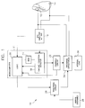
- Figure 1 is a schematic block diagram illustrating the various components of the non-committed defibrillation system of the present invention.
- Figures 2 and 3 are flow charts illustrating the procedural steps for implementing the abort algorithm of the present invention.
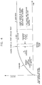
- Figure 4 is an illustration of the particular time intervals of the abort algorithm related to the charging and discharging of a defibrillation capacitor.
- the non-committed defibrillation system includes sensing/discharging electrodes 12 and 14 mounted on or about the heart which are connected to ECG sense amplifier 16.
- the ECG amplifier 16 may contain one or more sense channels, but also includes automatic gain control (AGC).
- AGC automatic gain control
- the ECG amplifier 16 is connected to a cardiac condition detector 18 and to logic 20 for analyzing the heart activity detected by the ECG amplifier 16.
- Logic 20 can be embodied as software, firmware, or in the form of conventional logic gates and circuits. A detailed description of a flow diagram of logic 20 is set forth hereinafter.
- the cardiac condition detector 18 includes the ability to measure time intervals between successive R-waves as well as other functions well known in the art for diagnosing the function of the heart.
- the logic 20 and cardiac condition detector 18 may be incorporated as one unit, such as for example, in a microcomputer 21 as shown, but regardless, include means for performing rate detection such as determining the R-R interval, probability density function (PDF) detection, and other arrhythmia monitoring schemes which are known in the art, and which are not part of the essence of the present invention.
- a memory 23 is also provided in the microcomputer 21, as is well known in the art, for storing cardiac condition information such as R-R wave intervals and programmable data.
- a charging circuit 22 is provided for charging the discharge capacitor 24.
- the charging circuit is connected to logic 20 for communicating therewith.
- a triggering circuit 26 for controlling the discharge of the capacitor 24.
- a manual disenable 28 is provided for causing the triggering circuit 26 to prevent the capacitor 24 from discharging to the electrodes 12 and 14.
- the triggering circuit 26 triggers the capacitor 24 to discharge through the electrodes 12 and 14 or through an internal load 30.
- FIGS 2 and 3 illustrate the logic flow pattern embodied by logic 20 of the system illustrated in Figure 1.
- the ECG sense amplifier 16 senses the electrical activity of the heart via electrodes 12 and 14. This information is analyzed by the cardiac condition detector 18.
- the abort algorithm is entered once an initial determination is made that the heart is in an arrhythmia. If it is determined that a tachycardia or other arrhythmia is present at step 32 by some other means or mechanism not considered part of the present invention, the capacitor 24 is charged to a selected level at step 34 to ultimately defibrillate the heart. Also, while the capacitor 24 is being charged in step 34, the electrical activity of the heart is continuously sensed by the ECG amplifier 16 to monitor the R-waves. Once the capacitor 24 is fully charged, a first delay of 200 msec is initiated at step 36.
- the first delay is programmable but preferably lasts approximately 200 msec.
- the ECG sense amplifier 16 is allowed to settle to facilitate discharge of the capacitor to be synchronized with a R-wave if necessary.
- this time window permits block out any effect that the charging circuit 22 may have on the automatic gain control circuitry in the ECG sense amplifier 16.
- a manual dump at step 38 can be accomplished by the manual disenable 28 during this time window should it be determined by a physician, for example, that it is not desirable to deliver the shock. If this latter step is chosen, the dump is made at step 40 to the internal load 30.
- Step 41A illustrates the selective nature of the abort algorithm.
- the physician/technician can program the device to employ or not to employ the abort algorithm. When not activated, only committed shocks would be delivered.
- step 41B it is determined whether a maximum number of aborts has already been effected during the current state of operation of the algorithm.
- step 41C there is preferably a maximum number of times that the algorithm can enter the non-committing period (referred to hereinafter). While this parameter can be reset by a physician/technician, it is normally fixed for the period of time between physician check-ups. In effect, the algorithm will permit only so many delays (and capacitor diversions) before going fully committed.
- the decision step 42 is entered for making a comparison of the most recent R-R interval, detected while charging the capacitors in step 34 (stored in memory 23), with a tachycardia primary rate cycle length limit (PCLL). One of two branches is taken depending on the result at step 42.
- PCLL tachycardia primary rate cycle length limit
- a second delay is initiated at step 44.
- This second delay is programmable and can last up to, but no more than 2 seconds. The purpose of this delay is to allow further monitoring of the heart activity before a decision to discharge or dump the capacitor 24 is made.
- This delay period is termed a non-committing period during which discharge of the capacitor 24 is not triggered unless a certain cardiac condition is detected. At this point, the indication after the first delay is that the arrhythmia might revert spontaneously.
- R-wave activity is constantly monitored by the cardiac condition detector 18 during the non-committing period.
- step 46 discharge of the defibrillation capacitor 24 is immediately effected in step 48 on the second R-wave of the first fast interval detected. If, on the other hand, the result in step 46 is negative, the post intervention (PI) routine 50 shown in Figure 3 is entered at the end of the non-committing period via a first track indicated in step 49A. The charge on the capacitor 24 is allowed to remain at this time. Also, after the shock delivered in step 48, the PI routine is entered via a second track indicated in step 49B.
- PI post intervention
- the electrical activity of the heart is continuously monitored at step 52 for a certain present period of time or certain present number of cardiac cycles.
- a determination is made at step 53 to determine if the arrhythmia has reverted.
- the details of steps 52 and 53 may involve many types of cardiac analysis not considered a part of the present invention. If the arrhythmia has reverted, it is determined in step 54A whether the PI routine was entered via track 1 (step 49A) or track 2 (step 49B). If the answer to the inquiry in step 54A is affirmative, then the triggering circuit 26 triggers the discharge of capacitor 24 through the internal load 30 at step 54B.
- step 55A If it is detected in step 53 that the arrhythmia has not reverted, then it is determined in step 55A whether the PI routine was entered via track 1 (step 49A) or track 2 (step 49B). An affirmative response in step 55A will cause the algorithm to continue from step 56. A negative response in step 55A will follow to step 55B in which it is determined if a programmable maximum number of shocks has been exceeded for a single arrhythmia episode. If this maximum is met, the algorithm enters a "wait" state as shown at step 55C during which time the algorithm can be reset by a physician/technician or by spontaneous reversion to normal heart rhythm. During the "wait" state, if the heart rate remains below the value of PCLL, the algorithm is reset.
- any new arrhythmia is considered a new arrhythmic episode whereas if the current arrhythmic state does not revert, the "wait state is continued but the heart rate is monitored and if the rate decreases to below PCLL, the algorithm resets. Otherwise, the capacitor is again charged in step 34.
- step 55A Should it be found in step 55A that the PI routine was entered via track 1, the charging circuit 22 is activated to ensure that the capacitor 24 is fully charged to the selected or appropriate level by effectively "topping off” the charge on the capacitor 24 at step 56. This step is sometimes necessary if the capacitor charge has leaked subsequent its initial charging or a higher energy shock is necessary if the arrhythmia has accelerated as determined in step 52. Thereafter, an optional 200 msec delay is entered at step 58 to allow for internal manual dump much like that shown at steps 38 and 40 in Figure 2. If no internal dump is made, a synchronization window is entered at steps 60, 62 and 64. In the synchronization window, a shock is delivered synchronized to an R-wave if one is detected. The term synchronized is intended to mean simultaneous with an R-wave or a programmed period of time after an R-wave.
- step 43 a check is made on the time interval from the most recent R-wave (PTOC) detected while charging the capacitor 24 in step 34 to the end of the 200 msec first delay interval. The purpose of this comparison is that any occurrence of an R-wave during the first delay, whether or not detected, is considered to be fast provided the interval is less than PCLL even if it occurs at the end of the first delay.
- PTOC most recent R-wave
- the abort algorithm of the present invention allows a precise determination of whether a detected arrhythmia has subsequently reverted before delivering a discharge to the patient. Therefore, unnecessary electrical shocks are avoided, preventing trauma.
- parameters such as PCLL, the first delay, the duration of the non-committing period and the duration of the synchronization window may be programmable or may vary dynamically with changes in cardiac activity.
- the terms preset or predetermined are meant to include variable such as dynamically changing.
- conditions such as the comparison in step 46 may be modified so as to require several (a predetermined or variable number) of fast R-R intervals.
Abstract
Description
- The present invention relates to an implantable automatic defibrillator and more particularly to a feature in an implantable automatic defibrillator for diverting the charge on a defibrillator capacitor to an internal load.
- In implantable cardiac treatment devices, such as an implantable defibrillator, a cardiac arrhythmia is detected based on sensed electrical and other activity of the heart. In defibrillation, the determination of a tachycardia, or fast beating heart, is indicative of impending ventricular fibrillation. Upon the determination of such an arrhythmia, a defibrillation capacitor is charged to a selected level for ultimately discharging and delivering an electrical shock to the heart.
- Oftentimes, the arrhythmia of the heart is temporary and does not further develop into fibrillation, but reverts to normal sinus rhythm. This can occur while the defibrillation capacitor is charging or shortly after the capacitor has been charged. If the capacitor is discharged to a heart in normal sinus rhythm, the result could be detrimental, and at the worst put the heart into an arrhythmia. In addition, a high energy defibrillation shock normally causes some trauma to the patient; thus an unnecessary shock is to be avoided.
- To avoid delivering an unnecessary defibrillation shock, it would be advantageous to delay the discharge of the defibrillation capacitor after it has been fully charged to allow further monitoring if there is an indication that the arrhythmia has reverted to normal sinus rhythm during the charging process.
- Some defibrillation devices incorporate delays for manually disenabling the capacitor discharge. See for example U.S. Patents to Bradley et al. (4,576,170) and Heilman et al. (4,210,149). These devices have built-in delays to allow the wearer to disenable the implantable device to prevent the delivery of a shock after the patient is audibly warned of an impending shock. The purpose of these devices is to allow the patient to override the implantable device in the event that a false detection occurs.
- These devices fail in that a truly accurate examination of the heart activity is not made when disenabling the device. Therefore, it is possible to ignore a malignant heart condition.
- It is a primary object of the present invention to provide a non-committed defibrillation/cardioversion system and algorithm in an implantable defibrillator whereby the heart activity is monitored during and after the charging of a defibrillation capacitor to further evaluate the heart condition before discharging the defibrillation capacitor.
- The present invention relates to an automatic implantable defibrillator having a non-committed defibrillation system algorithm. The defibrillator includes an ECG amplifier with automatic gain control (AGC) which detects the electrical activity of the heart for analysis by a cardiac condition detector. Logic is provided which receives input from the ECG amplifier and the cardiac condition detector for analyzing the heart activity.
- The cardiac condition detector is connected to a charging circuit for charging at least one defibrillation capacitor. (One capacitor will be referred to hereinafter, but it is to be understood that a plurality of capacitors may be provided.) A triggering circuit is provided which is controlled by the logic to actuate the discharge of the defibrillation capacitor to the heart. In addition, a manual disenable circuit is provided which can override the logic to prevent discharge of the defibrillation capacitor.
- The non-committed defibrillation algorithm (hereinafter also referred to as the abort algorithm) operates with R-wave sensing during the charging of the defibrillation capacitor and is accomplished by firmware embodied by the logic. The algorithm begins upon the determination of an arrhythmia. The capacitor is charged while the heart activity is simultaneously monitored. Once the capacitor has been charged to the selected level, the first of two possible delays occurs.
- The first delay is programmable but is expected to be approximately 200 msec long. During this time the ECG amplifier is allowed to settle after the charging circuit is deactivated to terminate any effects that the AGC has in the ECG amplifier. Further, this settling time is required because capacitor discharge is desired to be synchronized with the sensing of an R-wave; the ECG amplifier can better detect R-waves after the charging circuit has settled. Another reason for the first delay is to allow manual diversion of the capacitor charge to an internal load should it otherwise be decided to divert the charge of the capacitor. At the end of the first delay, a check is made on the duration of the last R-R interval detected while charging the capacitor. A comparison is made between this R-R interval and a programmable tachycardia primary rate cycle length limit (PCLL).
- If the last R-R interval is greater than PCLL, a second delay is initiated. This second delay is programmable, is referred to as the non-committing period, and is expected to be set at approximately 2 seconds. The purpose of the second delay is to allow detection to monitor the cardiac activity further after capacitor discharge but before making the decision to discharge the capacitor or dump the charge internally. If any R-R interval detected during this interval is less than PCLL, this indicates that the arrhythmia has not reverted and that the capacitor charge is to be delivered to the patient immediately, but synchronously. If no rapid interval is detected during this time, the shock is not delivered and a post intervention (PI) monitoring routine is entered at the end of the non-committing period. The PI routine is entered also after the synchronous shock.
- During the PI routine, further cardiac condition detection is performed and if the arrhythmia has reverted, then the capacitor charge is dumped internally. If, however, the arrhythmia has not reverted, the capacitor is brought up to an appropriate level (should leakage have occurred), a synchronization window is initiated, and the capacitor is discharged synchronized to an R-wave if one is detected during the synchronization window, and otherwise the capacitor is discharged at the end of the synchronization window.
- If the last R-R interval is less than or equal to PCLL, a check is made on the time interval from the most recently sensed R-wave (PTOC) during capacitor charging to the end of the 200 msec interval. One of two results are possible. First, if this time interval is greater than PCLL, the non-committing period is entered and the procedure described therewith is followed. Second, if this time interval is less than or equal to PCLL, the synchronization window is entered to shock the heart synchronously if possible.
- The abort algorithm of the present invention can be used in cardioverting a high rate tachycardia (often known as a malignant tachyarrhythmia) with a relatively low energy and synchronized shock, as well as ventricular fibrillation with a relatively high energy synchronous or asynchronous shock.
- The above and other objects and advantages of the present invention will become more apparent when reference is made to the following description taken in conjunction with the accompanying drawings.
- Figure 1 is a schematic block diagram illustrating the various components of the non-committed defibrillation system of the present invention.
- Figures 2 and 3 are flow charts illustrating the procedural steps for implementing the abort algorithm of the present invention.
- Figure 4 is an illustration of the particular time intervals of the abort algorithm related to the charging and discharging of a defibrillation capacitor.
- Referring first to Figure 1, the various components of the present invention will be described. The non-committed defibrillation system, generally showed at 10, includes sensing/discharging
electrodes ECG sense amplifier 16. TheECG amplifier 16 may contain one or more sense channels, but also includes automatic gain control (AGC). - The
ECG amplifier 16 is connected to acardiac condition detector 18 and tologic 20 for analyzing the heart activity detected by theECG amplifier 16.Logic 20 can be embodied as software, firmware, or in the form of conventional logic gates and circuits. A detailed description of a flow diagram oflogic 20 is set forth hereinafter. Thecardiac condition detector 18 includes the ability to measure time intervals between successive R-waves as well as other functions well known in the art for diagnosing the function of the heart. - The
logic 20 andcardiac condition detector 18 may be incorporated as one unit, such as for example, in amicrocomputer 21 as shown, but regardless, include means for performing rate detection such as determining the R-R interval, probability density function (PDF) detection, and other arrhythmia monitoring schemes which are known in the art, and which are not part of the essence of the present invention. In addition, amemory 23 is also provided in themicrocomputer 21, as is well known in the art, for storing cardiac condition information such as R-R wave intervals and programmable data. - A
charging circuit 22 is provided for charging thedischarge capacitor 24. The charging circuit is connected tologic 20 for communicating therewith. Also connected tologic 20 is a triggeringcircuit 26 for controlling the discharge of thecapacitor 24. In addition, amanual disenable 28 is provided for causing the triggeringcircuit 26 to prevent thecapacitor 24 from discharging to theelectrodes circuit 26 triggers thecapacitor 24 to discharge through theelectrodes internal load 30. - Referring now to Figures 2 - 4, together with Figure 1, the abort algorithm will now be described. Figures 2 and 3 illustrate the logic flow pattern embodied by
logic 20 of the system illustrated in Figure 1. TheECG sense amplifier 16 senses the electrical activity of the heart viaelectrodes cardiac condition detector 18. The abort algorithm is entered once an initial determination is made that the heart is in an arrhythmia. If it is determined that a tachycardia or other arrhythmia is present atstep 32 by some other means or mechanism not considered part of the present invention, thecapacitor 24 is charged to a selected level atstep 34 to ultimately defibrillate the heart. Also, while thecapacitor 24 is being charged instep 34, the electrical activity of the heart is continuously sensed by theECG amplifier 16 to monitor the R-waves. Once thecapacitor 24 is fully charged, a first delay of 200 msec is initiated atstep 36. - The first delay is programmable but preferably lasts approximately 200 msec. During this time, the
ECG sense amplifier 16 is allowed to settle to facilitate discharge of the capacitor to be synchronized with a R-wave if necessary. Also, this time window permits block out any effect that the chargingcircuit 22 may have on the automatic gain control circuitry in theECG sense amplifier 16. In addition, a manual dump atstep 38 can be accomplished by themanual disenable 28 during this time window should it be determined by a physician, for example, that it is not desirable to deliver the shock. If this latter step is chosen, the dump is made atstep 40 to theinternal load 30. - Otherwise, the
preliminary steps 41A-41C are entered.Step 41A illustrates the selective nature of the abort algorithm. The physician/technician can program the device to employ or not to employ the abort algorithm. When not activated, only committed shocks would be delivered. Instep 41B, it is determined whether a maximum number of aborts has already been effected during the current state of operation of the algorithm. In addition, as shown instep 41C, there is preferably a maximum number of times that the algorithm can enter the non-committing period (referred to hereinafter). While this parameter can be reset by a physician/technician, it is normally fixed for the period of time between physician check-ups. In effect, the algorithm will permit only so many delays (and capacitor diversions) before going fully committed. Therefore, patients with spaced short-run ventricular tachyarrhythmias will not cause the device to waste battery charge due to repeated charge and subsequent internal discharge of the capacitor. As indicated in Figure 2, once this maximum value is met, the device will deliver committed shocks. Themicrocomputer 21 keeps track of the various parameters specified insteps 41A-41C. - If the abort algorithm is turned on and none of the maximums specified in
steps decision step 42 is entered for making a comparison of the most recent R-R interval, detected while charging the capacitors in step 34 (stored in memory 23), with a tachycardia primary rate cycle length limit (PCLL). One of two branches is taken depending on the result atstep 42. - If this R-R interval is greater than PCLL, a second delay is initiated at
step 44. This second delay is programmable and can last up to, but no more than 2 seconds. The purpose of this delay is to allow further monitoring of the heart activity before a decision to discharge or dump thecapacitor 24 is made. This delay period is termed a non-committing period during which discharge of thecapacitor 24 is not triggered unless a certain cardiac condition is detected. At this point, the indication after the first delay is that the arrhythmia might revert spontaneously. R-wave activity is constantly monitored by thecardiac condition detector 18 during the non-committing period. - During the non-committing period, if any R-R interval detected is less than PCLL, at
step 46, discharge of thedefibrillation capacitor 24 is immediately effected instep 48 on the second R-wave of the first fast interval detected. If, on the other hand, the result instep 46 is negative, the post intervention (PI) routine 50 shown in Figure 3 is entered at the end of the non-committing period via a first track indicated instep 49A. The charge on thecapacitor 24 is allowed to remain at this time. Also, after the shock delivered instep 48, the PI routine is entered via a second track indicated instep 49B. - Referring now to Figure 3, in the PI routine, the electrical activity of the heart is continuously monitored at
step 52 for a certain present period of time or certain present number of cardiac cycles. After the time-out or count-out instep 52, based on the continuously monitored cardiac activity, a determination is made atstep 53 to determine if the arrhythmia has reverted. The details ofsteps step 54A whether the PI routine was entered via track 1 (step 49A) or track 2 (step 49B). If the answer to the inquiry instep 54A is affirmative, then the triggeringcircuit 26 triggers the discharge ofcapacitor 24 through theinternal load 30 atstep 54B. - If it is detected in
step 53 that the arrhythmia has not reverted, then it is determined instep 55A whether the PI routine was entered via track 1 (step 49A) or track 2 (step 49B). An affirmative response instep 55A will cause the algorithm to continue fromstep 56. A negative response instep 55A will follow to step 55B in which it is determined if a programmable maximum number of shocks has been exceeded for a single arrhythmia episode. If this maximum is met, the algorithm enters a "wait" state as shown atstep 55C during which time the algorithm can be reset by a physician/technician or by spontaneous reversion to normal heart rhythm. During the "wait" state, if the heart rate remains below the value of PCLL, the algorithm is reset. Thereafter, any new arrhythmia is considered a new arrhythmic episode whereas if the current arrhythmic state does not revert, the "wait state is continued but the heart rate is monitored and if the rate decreases to below PCLL, the algorithm resets. Otherwise, the capacitor is again charged instep 34. - Should it be found in
step 55A that the PI routine was entered viatrack 1, the chargingcircuit 22 is activated to ensure that thecapacitor 24 is fully charged to the selected or appropriate level by effectively "topping off" the charge on thecapacitor 24 atstep 56. This step is sometimes necessary if the capacitor charge has leaked subsequent its initial charging or a higher energy shock is necessary if the arrhythmia has accelerated as determined instep 52. Thereafter, an optional 200 msec delay is entered atstep 58 to allow for internal manual dump much like that shown atsteps steps - If after the first delay in
step 42, it is determined that the most recent R-R interval detected while charging thecapacitor 24 instep 34 is less than or equal to PCLL, the branch on the left side of Figure 2 is taken to step 43. Instep 43, a check is made on the time interval from the most recent R-wave (PTOC) detected while charging thecapacitor 24 instep 34 to the end of the 200 msec first delay interval. The purpose of this comparison is that any occurrence of an R-wave during the first delay, whether or not detected, is considered to be fast provided the interval is less than PCLL even if it occurs at the end of the first delay. Consequently, if this interval is less than or equal to the PCLL, there is no indication that the heart rhythm is still not abnormally fast, and the algorithm goes to step 60 in Figure 3, and shocks the heart synchronously if possible and otherwise asynchronously. Otherwise, the non-committing period atstep 44 is entered and the steps there are executed as previously described. - The abort algorithm of the present invention allows a precise determination of whether a detected arrhythmia has subsequently reverted before delivering a discharge to the patient. Therefore, unnecessary electrical shocks are avoided, preventing trauma. Several modifications of the algorithm as described above can be made. First, parameters such as PCLL, the first delay, the duration of the non-committing period and the duration of the synchronization window may be programmable or may vary dynamically with changes in cardiac activity. In this regard, the terms preset or predetermined are meant to include variable such as dynamically changing. Furthermore, conditions such as the comparison in
step 46, may be modified so as to require several (a predetermined or variable number) of fast R-R intervals. Accordingly, other tests or analysis of the cardiac activity can be made during the non-committing period to trigger or inhibit discharge of the defibrillation capacitors to the heart. In this regard, physiological indicators of cardiac arrhythmias such as, blood pressure or oxygenation, can be employed in the algorithm in addition to or in substitution for heart rate. It is also possible to operate the algorithm without the first delay period ofstep 36. In this case, the algorithm would be implemented withoutstep 43 so that a positive response instep 43 would follow directly to step 60. - The above description is intended by way of example only and is not intended to limit the present invention in any way except as set forth in the following claims.
Claims (25)
- A method for defibrillating/cardioverting the heart comprising the steps of:(a) sensing the electrical activity of the heart including the interval between successive R-waves of the ECG;(b) charging a defibrillation capacitor to a predetermined voltage level upon detecting an arrhythmia of the heart;(c) storing the interval between successive R-waves during the step of charging the defibrillation capacitor;(d) providing a first delay of a first predetermined period of time subsequent to said capacitor being charged to said predetermined level;(e) comparing a most recent of intervals between successive R-waves detected during the step of charging with a preset value after said first delay;(f) providing a second delay of a second predetermined period of time if said most recent interval between successive R-waves is greater than said preset value as determined in step (e);(g) comparing intervals between successive R-waves detected during the second delay with said preset value; and(h) discharging said defibrillation capacitor if any interval between successive R-waves detected during the second delay is less than said preset value as determined in step (g).
- The method of claim 1, wherein said step (h) of discharging further comprises the step of synchronizing discharge with a second of R-waves of a first R-R interval less than said present value.
- The method of claim 1, and further comprising the steps of:(i) determining a time interval between a most recent R-wave detected during the step of charging and the end of said first delay of said first predetermined period of time if said most recent interval of successive R-waves is less than or equal to said preset value as determined in step (e);(j) comparing said time interval of step (i) with a preset time interval; and(k) performing steps (f)-(h) if said time interval of step (i) exceeds said preset time interval as determined in step (j).
- The method of claim 3, and further comprising the steps of:(l) determining whether the detected arrhythmia has reverted if no interval between successive R-waves is less than said preset value as determined in step (g) or after the step (h) of discharging;(m) diverting said predetermined voltage level of said defibrillation capacitor to an internal load if the arrhythmia has reverted as determined in step (l);(n) providing a synchronization time window of a third predetermined period of time if a detected arrhythmia has not reverted as determined in step (l);(o) detecting an R-wave during said synchronization time window;(p) discharging said defibrillation capacitor at the occurrence of a detected R-wave in step (o); and(q) discharging said defibrillation capacitor at the end of said synchronization time window if no R-wave is detected during the synchronization time window.
- The method of claim 1, and further comprising the step of diverting said predetermined voltage level of said capacitor to an internal load during said first delay should an operator desire to prevent discharge to the heart of a patient.
- The method of claim 4, and further comprising the step of ensuring that the charge on said defibrillation capacitor is at an appropriate voltage level if a detected arrhythmia has not reverted as determined in step (l).
- The method of claim 1, wherein said first predetermined period of time is 200 milliseconds and said second predetermined period of time is 2 seconds.
- The method of claim 4, wherein said third predetermined period of time is 2 seconds.
- A system for defibrillating/cardioverting the heart comprising:
means for sensing the electrical activity of the heart including the interval between successive R-waves of the ECG;
means for detecting an arrhythmia of the heart;
means for storing the interval between successive R-waves;
defibrillation capacitor means;
means for charging said defibrillation capacitor means to a predetermined voltage level upon detecting an arrhythmia of the heart;
means for triggering the discharge of said defibrillation capacitor means; and
logic means for providing a first delay of a first predetermined period of time subsequent to said capacitor being charged to said predetermined level and a second delay of a second predetermined period of time subsequent to said first delay, said logic means comparing a most recent of intervals between successive R-waves detected during charging of the defibrillation capacitor means with a preset value during said first delay, entering said second delay of said second predetermined period of time if said most recent interval between successive R-waves is greater than said preset value, and discharging said defibrillation capacitor to the heart if any interval between successive R-waves is less than said preset value during said second delay. - The system of claim 9, wherein said logic means further determines a variable time interval between a most recent R-wave detected while charging the defibrillation capacitor means and the end of said first delay of said first predetermined period of time if said most recent interval of successive R-waves is less than or equal to said preset value during said first delay, and compares said variable time interval with a preset time interval to enter said second delay if said variable time interval exceeds said preset time interval.
- The system of claim 10, and further comprising an internal load, and wherein said logic means further determines if a detected arrhythmia has reverted if no R-R interval detected during the second delay is less than said present value or after discharge of the defibrillation capacitor means if an R-R interval is less than said present value, and operates the means for triggering to divert said predetermined voltage level of said defibrillation capacitor to said internal load if the arrhythmia has reverted, the logic means further providing a synchronization time window of a third predetermined period of time if a detected arrhythmia has not reverted, said means for sensing detecting an R-wave during said third predetermined period of time and said logic means operating the means for triggering to effect discharge of said defibrillation capacitor at the occurrence of a detected R-wave during said synchronization time window or effecting discharge of said defibrillation capacitor at the end of said synchronization time window if no R-wave is detected during said third predetermined period of time.
- The method of claim 11, wherein said logic means triggers said means for charging to charge said defibrillation capacitor means to an appropriate voltage level if a detected arrhythmia has not reverted after said second delay and charge on the defibrillation capacitor means has leaked to below the predetermined voltage level.
- The system of claim 11, wherein said logic means is programmable and said first predetermined period of time is 200 milliseconds and said second predetermined period of time is 2 seconds.
- The system of claim 11, wherein said third predetermined period of time is two seconds.
- A method of non-committed defibrillation/cardioversion of the heart comprising the steps of:(a) sensing the electrical activity of the heart including the interval between successive R-waves of the ECG;(b) charging a defibrillation capacitor to a predetermined voltage level upon detecting an arrhythmia of the heart;(c) storing the interval between successive R-waves during the step of charging the defibrillation capacitor;(d) comparing a most recent of intervals between successive R-waves detected during the step of charging with a first preset value;(e) providing a non-committing period of a first predetermined period of time if said most recent interval between successive R-waves is greater than said preset value as determined in step (d);(f) comparing intervals between successive R-waves detected during the non-committing period with a second preset value; and(g) discharging said defibrillation capacitor if any interval between successive R-waves detected during the non-committing period is less than said preset value as determined in step (f).
- The method of claim 15, wherein the first preset value and the second preset value are equal.
- The method of claim 15, wherein said step (g) of discharging further comprises the step of synchronizing discharge with a second of R-waves of a first R-R interval less than said present value.
- The method of claim 16, wherein the first preset value and the second preset value are equal to a tachycardia primary rate cycle length limit.
- The method of claim 15, and further comprising the steps of:(h) providing a synchronization time window of a second predetermined period of time if said most recent interval of successive R-waves is less than or equal to said preset value as determined in step (d);(i) detecting an R-wave during said synchronization time window; and(j) discharging said defibrillation capacitor synchronized to a detected R-wave in step (i) and otherwise discharging the defibrillation capacitor at the end of the synchronization time window if no R-wave is detected.
- The method of claim 15, and further comprising the steps of:(k) determining whether the detected arrhythmia has reverted if no interval between successive R-waves is less than said preset value as determined in step (f) or after the step (g) of discharging;(l) diverting said predetermined voltage level of said defibrillation capacitor to an internal load if the arrhythmia has reverted as determined in step (k);(m) providing a synchronization time window of a second predetermined period of time if a detected arrhythmia has not reverted as determined in step (k);(n) detecting an R-wave during said synchronization time window;(o) discharging said defibrillation capacitor at the occurrence of a detected R-wave in step (n); and(p) discharging said defibrillation capacitor at the end of said synchronization time window if no R-wave is detected during the synchronization time window.
- A method for defibrillating/cardioverting the heart comprising the steps of:(a) sensing the electrical activity of the heart or a physiological indicator of an arrhythmia;(b) detecting an arrhythmia of the heart based on the sensed electrical activity of the heart or physiological indicator;(c) charging a defibrillation capacitor to a predetermined voltage level upon detecting an arrhythmia of the heart;(d) storing data related to the cardiac function of the heart during the step of charging;(e) detecting whether a first predetermined condition of the heart occurs during the step of charging;(f) providing a non-committing period of a first predetermined period of time if the first predetermined condition of the heart does not occur during the step of charging as determined in step (e);(g) detecting whether a second predetermined condition of the heart occurs during said non-committing period based on the sensed electrical activity or physiological indicator; and(h) discharging said defibrillation capacitor if said second predetermined condition of the heart is detected during said second delay determined in step (g).
- The method of claim 21, and wherein said first predetermined condition comprises a time interval of consecutive R-waves being less than a preset value.
- The method of claim 21, wherein the second predetermined condition comprises any time interval of consecutive R-waves occurring during the non-committing period being less than a preset value.
- The method of claim 21, and further comprising the steps of:(i) providing a synchronization time window of a second predetermined period of time if said first predetermined condition is detected as determined in step (e);(j) detecting an R-wave during said synchronization time window; and(k) discharging said defibrillation capacitor synchronized to a detected R-wave in step (j) and otherwise discharging the defibrillation capacitor at the end of the synchronization time window if no R-wave is detected.
- The method of claim 21, and further comprising the steps of:(l) determining whether the detected arrhythmia has reverted if the second predetermined condition is not detected as determined in step (g) or after the step (h) of discharging;(m) diverting said predetermined voltage level of said defibrillation capacitor to an internal load if the arrhythmia has reverted as determined in step (l);(n) providing a synchronization time window of a second predetermined period of time if a detected arrhythmia has not reverted as determined in step (l);(o) detecting an R-wave during said synchronization time window;(p) discharging said defibrillation capacitor at the occurrence of a detected R-wave in step (o); and(q) discharging said defibrillation capacitor at the end of said synchronization time window if no R-wave is detected during the synchronization time window.
Applications Claiming Priority (1)
| Application Number | Priority Date | Filing Date | Title |
|---|---|---|---|
| US07/642,337 US5179945A (en) | 1991-01-17 | 1991-01-17 | Defibrillation/cardioversion system with multiple evaluation of heart condition prior to shock delivery |
Publications (2)
| Publication Number | Publication Date |
|---|---|
| EP0568739A1 true EP0568739A1 (en) | 1993-11-10 |
| EP0568739B1 EP0568739B1 (en) | 1999-07-14 |
Family
ID=24576160
Family Applications (1)
| Application Number | Title | Priority Date | Filing Date |
|---|---|---|---|
| EP92304020A Revoked EP0568739B1 (en) | 1991-01-17 | 1992-05-05 | Non-committed defibrillation/cardioversion system |
Country Status (7)
| Country | Link |
|---|---|
| US (1) | US5179945A (en) |
| EP (1) | EP0568739B1 (en) |
| AT (1) | ATE182082T1 (en) |
| DE (1) | DE69229594T2 (en) |
| DK (1) | DK0568739T3 (en) |
| ES (1) | ES2137174T3 (en) |
| GR (1) | GR3031364T3 (en) |
Families Citing this family (192)
| Publication number | Priority date | Publication date | Assignee | Title |
|---|---|---|---|---|
| US5439481A (en) * | 1992-02-26 | 1995-08-08 | Angeion Corporation | Semi-automatic atrial and ventricular cardioverter defibrillator |
| US5330504A (en) * | 1992-03-16 | 1994-07-19 | Telectronics Pacing Systems, Inc. | Cardioverting defibrillating device with off-line ECG analysis |
| US5366484A (en) * | 1992-04-09 | 1994-11-22 | Angeion Corporation | Short-pulse cardioversion system for an implantable cardioverter defibrillator |
| US5342401A (en) * | 1992-08-19 | 1994-08-30 | The Regents Of The University Of California | Real time cardiac arrhythmia stabilizing system |
| US5486198A (en) * | 1994-08-12 | 1996-01-23 | Ayers; Gregory M. | Atrial defibrillator and method for providing interval timing of successive intervals prior to cardioversion |
| US5545182A (en) * | 1994-09-21 | 1996-08-13 | Intermedics, Inc. | Cardioverter/defibrillator shock timing function |
| US5620469A (en) * | 1994-10-11 | 1997-04-15 | Angeion Corporation | Stepped cardioversion system for an implantable cardioverter defibrillator |
| US5611815A (en) * | 1994-12-08 | 1997-03-18 | Heartstream, Inc. | Defibrillator with training features |
| US5507780A (en) * | 1995-01-25 | 1996-04-16 | Finch; David P. | Selective default data storage for an implantable atrial defibrillator |
| US5632766A (en) * | 1995-08-11 | 1997-05-27 | Cardiac Pacemakers, Inc. | Ventricular defibrillation by coordination of shocks with sensed coarse VF complexes |
| US6029085A (en) * | 1997-04-09 | 2000-02-22 | Survivalink Corporation | Charging and safety control for automated external defibrillator and method |
| US6112117A (en) | 1997-05-06 | 2000-08-29 | Cardiac Pacemakers, Inc. | Method and apparatus for treating cardiac arrhythmia using electrogram features |
| US6501990B1 (en) * | 1999-12-23 | 2002-12-31 | Cardiac Pacemakers, Inc. | Extendable and retractable lead having a snap-fit terminal connector |
| US6463334B1 (en) | 1998-11-02 | 2002-10-08 | Cardiac Pacemakers, Inc. | Extendable and retractable lead |
| US6169923B1 (en) | 1999-04-23 | 2001-01-02 | Pacesetter, Inc. | Implantable cardioverter-defibrillator with automatic arrhythmia detection criteria adjustment |
| US8064997B2 (en) * | 1999-05-21 | 2011-11-22 | Cardiac Pacemakers, Inc. | Method and apparatus for treating irregular ventricular contractions such as during atrial arrhythmia |
| US6430438B1 (en) * | 1999-05-21 | 2002-08-06 | Cardiac Pacemakers, Inc. | Cardiac rhythm management system with atrial shock timing optimization |
| US6976950B2 (en) * | 2000-04-14 | 2005-12-20 | Solace Therapeutics, Inc. | Implantable valved pressure attenuation device |
| US7039461B1 (en) * | 2000-05-13 | 2006-05-02 | Cardiac Pacemakers, Inc. | Cardiac pacing system for prevention of ventricular fibrillation and ventricular tachycardia episode |
| US6847842B1 (en) | 2000-05-15 | 2005-01-25 | Cardiac Pacemakers, Inc. | Method and apparatus for reducing early recurrence of atrial fibrillation with defibrillation shock therapy |
| US6704597B1 (en) * | 2000-07-20 | 2004-03-09 | Cardiac Pacemakers, Inc. | Apparatus and method for energy management in atrial defibrillator |
| US7369890B2 (en) * | 2000-11-02 | 2008-05-06 | Cardiac Pacemakers, Inc. | Technique for discriminating between coordinated and uncoordinated cardiac rhythms |
| US6689117B2 (en) * | 2000-12-18 | 2004-02-10 | Cardiac Pacemakers, Inc. | Drug delivery system for implantable medical device |
| US20040019287A1 (en) * | 2002-07-26 | 2004-01-29 | Harley White | Similarity recovery post shock |
| US7920917B2 (en) * | 2003-07-17 | 2011-04-05 | Physio-Control, Inc. | External defibrillator and methods for operating the external defibrillator |
| US20040158289A1 (en) * | 2002-11-30 | 2004-08-12 | Girouard Steven D. | Method and apparatus for cell and electrical therapy of living tissue |
| US7627373B2 (en) * | 2002-11-30 | 2009-12-01 | Cardiac Pacemakers, Inc. | Method and apparatus for cell and electrical therapy of living tissue |
| US7189204B2 (en) * | 2002-12-04 | 2007-03-13 | Cardiac Pacemakers, Inc. | Sleep detection using an adjustable threshold |
| US7392081B2 (en) * | 2003-02-28 | 2008-06-24 | Cardiac Pacemakers, Inc. | Subcutaneous cardiac stimulator employing post-shock transthoracic asystole prevention pacing |
| US20050004615A1 (en) * | 2003-04-11 | 2005-01-06 | Sanders Richard S. | Reconfigurable implantable cardiac monitoring and therapy delivery device |
| US7570997B2 (en) | 2003-04-11 | 2009-08-04 | Cardiac Pacemakers, Inc. | Subcutaneous cardiac rhythm management with asystole prevention therapy |
| US7529592B2 (en) | 2003-04-11 | 2009-05-05 | Cardiac Pacemakers, Inc. | Subcutaneous electrode and lead with temporary pharmacological agents |
| US7499750B2 (en) * | 2003-04-11 | 2009-03-03 | Cardiac Pacemakers, Inc. | Noise canceling cardiac electrodes |
| US7236819B2 (en) | 2003-04-11 | 2007-06-26 | Cardiac Pacemakers, Inc. | Separation of a subcutaneous cardiac signal from a plurality of composite signals |
| US20040204735A1 (en) * | 2003-04-11 | 2004-10-14 | Shiroff Jason Alan | Subcutaneous dissection tool incorporating pharmacological agent delivery |
| US7389138B2 (en) * | 2003-04-11 | 2008-06-17 | Cardiac Pacemakers, Inc. | Electrode placement determination for subcutaneous cardiac monitoring and therapy |
| US7218966B2 (en) * | 2003-04-11 | 2007-05-15 | Cardiac Pacemakers, Inc. | Multi-parameter arrhythmia discrimination |
| US20040230272A1 (en) * | 2003-04-11 | 2004-11-18 | Cates Adam W. | Subcutaneous lead with temporary pharmacological agents |
| US20040220626A1 (en) * | 2003-04-11 | 2004-11-04 | Wagner Darrell Orvin | Distributed subcutaneous defibrillation system |
| US7047071B2 (en) | 2003-04-11 | 2006-05-16 | Cardiac Pacemakers, Inc. | Patient stratification for implantable subcutaneous cardiac monitoring and therapy |
| US7117035B2 (en) | 2003-04-11 | 2006-10-03 | Cardiac Pacemakers, Inc. | Subcutaneous cardiac stimulation system with patient activity sensing |
| US7566318B2 (en) * | 2003-04-11 | 2009-07-28 | Cardiac Pacemakers, Inc. | Ultrasonic subcutaneous dissection tool incorporating fluid delivery |
| US7555335B2 (en) | 2003-04-11 | 2009-06-30 | Cardiac Pacemakers, Inc. | Biopotential signal source separation using source impedances |
| US20040204734A1 (en) * | 2003-04-11 | 2004-10-14 | Wagner Darrell Orvin | Tunneling tool with subcutaneous transdermal illumination |
| US7702399B2 (en) * | 2003-04-11 | 2010-04-20 | Cardiac Pacemakers, Inc. | Subcutaneous electrode and lead with phoresis based pharmacological agent delivery |
| US20040220628A1 (en) * | 2003-04-11 | 2004-11-04 | Wagner Darrell Orvin | Subcutaneous defibrillation timing correlated with induced skeletal muscle contraction |
| US7349742B2 (en) * | 2003-04-11 | 2008-03-25 | Cardiac Pacemakers, Inc. | Expandable fixation elements for subcutaneous electrodes |
| US7499758B2 (en) * | 2003-04-11 | 2009-03-03 | Cardiac Pacemakers, Inc. | Helical fixation elements for subcutaneous electrodes |
| US7865233B2 (en) | 2003-04-11 | 2011-01-04 | Cardiac Pacemakers, Inc. | Subcutaneous cardiac signal discrimination employing non-electrophysiologic signal |
| US7302294B2 (en) * | 2003-04-11 | 2007-11-27 | Cardiac Pacemakers, Inc. | Subcutaneous cardiac sensing and stimulation system employing blood sensor |
| US7979122B2 (en) * | 2003-04-11 | 2011-07-12 | Cardiac Pacemakers, Inc. | Implantable sudden cardiac death prevention device with reduced programmable feature set |
| US20040230230A1 (en) * | 2003-04-11 | 2004-11-18 | Lindstrom Curtis Charles | Methods and systems involving subcutaneous electrode positioning relative to a heart |
| US8116868B2 (en) | 2003-04-11 | 2012-02-14 | Cardiac Pacemakers, Inc. | Implantable device with cardiac event audio playback |
| US7493175B2 (en) | 2003-04-11 | 2009-02-17 | Cardiac Pacemakers, Inc. | Subcutaneous lead with tined fixation |
| US20040215240A1 (en) * | 2003-04-11 | 2004-10-28 | Lovett Eric G. | Reconfigurable subcutaneous cardiac device |
| US7787946B2 (en) * | 2003-08-18 | 2010-08-31 | Cardiac Pacemakers, Inc. | Patient monitoring, diagnosis, and/or therapy systems and methods |
| US20050107838A1 (en) * | 2003-09-18 | 2005-05-19 | Lovett Eric G. | Subcutaneous cardiac rhythm management with disordered breathing detection and treatment |
| US7396333B2 (en) * | 2003-08-18 | 2008-07-08 | Cardiac Pacemakers, Inc. | Prediction of disordered breathing |
| US7887493B2 (en) * | 2003-09-18 | 2011-02-15 | Cardiac Pacemakers, Inc. | Implantable device employing movement sensing for detecting sleep-related disorders |
| US8002553B2 (en) | 2003-08-18 | 2011-08-23 | Cardiac Pacemakers, Inc. | Sleep quality data collection and evaluation |
| US8606356B2 (en) | 2003-09-18 | 2013-12-10 | Cardiac Pacemakers, Inc. | Autonomic arousal detection system and method |
| US20060247693A1 (en) | 2005-04-28 | 2006-11-02 | Yanting Dong | Non-captured intrinsic discrimination in cardiac pacing response classification |
| US7774064B2 (en) * | 2003-12-12 | 2010-08-10 | Cardiac Pacemakers, Inc. | Cardiac response classification using retriggerable classification windows |
| US8521284B2 (en) * | 2003-12-12 | 2013-08-27 | Cardiac Pacemakers, Inc. | Cardiac response classification using multisite sensing and pacing |
| US20050215884A1 (en) * | 2004-02-27 | 2005-09-29 | Greicius Michael D | Evaluation of Alzheimer's disease using an independent component analysis of an individual's resting-state functional MRI |
| US7706866B2 (en) * | 2004-06-24 | 2010-04-27 | Cardiac Pacemakers, Inc. | Automatic orientation determination for ECG measurements using multiple electrodes |
| US7797036B2 (en) * | 2004-11-30 | 2010-09-14 | Cardiac Pacemakers, Inc. | Cardiac activation sequence monitoring for ischemia detection |
| US7890159B2 (en) * | 2004-09-30 | 2011-02-15 | Cardiac Pacemakers, Inc. | Cardiac activation sequence monitoring and tracking |
| US7457664B2 (en) | 2005-05-09 | 2008-11-25 | Cardiac Pacemakers, Inc. | Closed loop cardiac resynchronization therapy using cardiac activation sequence information |
| US7509170B2 (en) * | 2005-05-09 | 2009-03-24 | Cardiac Pacemakers, Inc. | Automatic capture verification using electrocardiograms sensed from multiple implanted electrodes |
| US7805185B2 (en) * | 2005-05-09 | 2010-09-28 | Cardiac Pacemakers, In. | Posture monitoring using cardiac activation sequences |
| US7917196B2 (en) * | 2005-05-09 | 2011-03-29 | Cardiac Pacemakers, Inc. | Arrhythmia discrimination using electrocardiograms sensed from multiple implanted electrodes |
| US7418293B2 (en) * | 2004-11-09 | 2008-08-26 | Cardiac Pacemakers, Inc. | Multiple pulse defibrillation for subcutaneous implantable cardiac devices |
| US7904152B2 (en) * | 2004-12-09 | 2011-03-08 | Physio-Control, Inc. | External defibrillator with charge advisory algorithm |
| US8818504B2 (en) | 2004-12-16 | 2014-08-26 | Cardiac Pacemakers Inc | Leadless cardiac stimulation device employing distributed logic |
| US7981065B2 (en) | 2004-12-20 | 2011-07-19 | Cardiac Pacemakers, Inc. | Lead electrode incorporating extracellular matrix |
| US8060219B2 (en) * | 2004-12-20 | 2011-11-15 | Cardiac Pacemakers, Inc. | Epicardial patch including isolated extracellular matrix with pacing electrodes |
| US7996072B2 (en) * | 2004-12-21 | 2011-08-09 | Cardiac Pacemakers, Inc. | Positionally adaptable implantable cardiac device |
| US7680534B2 (en) | 2005-02-28 | 2010-03-16 | Cardiac Pacemakers, Inc. | Implantable cardiac device with dyspnea measurement |
| US7392086B2 (en) * | 2005-04-26 | 2008-06-24 | Cardiac Pacemakers, Inc. | Implantable cardiac device and method for reduced phrenic nerve stimulation |
| US8391990B2 (en) | 2005-05-18 | 2013-03-05 | Cardiac Pacemakers, Inc. | Modular antitachyarrhythmia therapy system |
| US20070049975A1 (en) * | 2005-09-01 | 2007-03-01 | Cates Adam W | Active can with dedicated defibrillation and sensing electrodes |
| US7731663B2 (en) | 2005-09-16 | 2010-06-08 | Cardiac Pacemakers, Inc. | System and method for generating a trend parameter based on respiration rate distribution |
| US7775983B2 (en) * | 2005-09-16 | 2010-08-17 | Cardiac Pacemakers, Inc. | Rapid shallow breathing detection for use in congestive heart failure status determination |
| US7927284B2 (en) * | 2005-09-16 | 2011-04-19 | Cardiac Pacemakers, Inc. | Quantifying hemodynamic response to drug therapy using implantable sensor |
| US8992436B2 (en) * | 2005-09-16 | 2015-03-31 | Cardiac Pacemakers, Inc. | Respiration monitoring using respiration rate variability |
| US20070118180A1 (en) | 2005-11-18 | 2007-05-24 | Quan Ni | Cardiac resynchronization therapy for improved hemodynamics based on disordered breathing detection |
| US7766840B2 (en) | 2005-12-01 | 2010-08-03 | Cardiac Pacemakers, Inc. | Method and system for heart failure status evaluation based on a disordered breathing index |
| US20070135847A1 (en) * | 2005-12-12 | 2007-06-14 | Kenknight Bruce H | Subcutaneous defibrillation system and method using same |
| US7662105B2 (en) * | 2005-12-14 | 2010-02-16 | Cardiac Pacemakers, Inc. | Systems and methods for determining respiration metrics |
| US7761158B2 (en) * | 2005-12-20 | 2010-07-20 | Cardiac Pacemakers, Inc. | Detection of heart failure decompensation based on cumulative changes in sensor signals |
| US7819816B2 (en) * | 2006-03-29 | 2010-10-26 | Cardiac Pacemakers, Inc. | Periodic disordered breathing detection |
| US20080004665A1 (en) * | 2006-06-29 | 2008-01-03 | Mccabe Aaron R | Determination of cardiac pacing parameters based on non-localized sensing |
| US7599741B2 (en) * | 2006-06-29 | 2009-10-06 | Cardiac Pacemakers, Inc. | Systems and methods for improving heart rate kinetics in heart failure patients |
| US8527048B2 (en) * | 2006-06-29 | 2013-09-03 | Cardiac Pacemakers, Inc. | Local and non-local sensing for cardiac pacing |
| US8209013B2 (en) * | 2006-09-14 | 2012-06-26 | Cardiac Pacemakers, Inc. | Therapeutic electrical stimulation that avoids undesirable activation |
| US8052611B2 (en) | 2007-03-14 | 2011-11-08 | Cardiac Pacemakers, Inc. | Method and apparatus for management of heart failure hospitalization |
| US8271080B2 (en) | 2007-05-23 | 2012-09-18 | Cardiac Pacemakers, Inc. | Decongestive therapy titration for heart failure patients using implantable sensor |
| US9037239B2 (en) | 2007-08-07 | 2015-05-19 | Cardiac Pacemakers, Inc. | Method and apparatus to perform electrode combination selection |
| US8265736B2 (en) | 2007-08-07 | 2012-09-11 | Cardiac Pacemakers, Inc. | Method and apparatus to perform electrode combination selection |
| EP2230993B1 (en) * | 2008-01-15 | 2018-08-15 | Cardiac Pacemakers, Inc. | Implantable medical device with antenna |
| US8401659B2 (en) * | 2008-01-15 | 2013-03-19 | Cardiac Pacemakers, Inc. | Implantable medical device with wireless communications |
| US9079033B2 (en) * | 2008-01-22 | 2015-07-14 | Cardiac Pacemakers, Inc. | Respiration as a trigger for therapy optimization |
| EP2254661B1 (en) | 2008-02-14 | 2015-10-07 | Cardiac Pacemakers, Inc. | Apparatus for phrenic stimulation detection |
| US8255052B2 (en) * | 2008-04-02 | 2012-08-28 | Cardiac Pacemakers, Inc. | Temperature based systems and methods for tachycardia discrimination and therapy |
| US8147415B2 (en) * | 2008-05-07 | 2012-04-03 | Cardiac Pacemakers, Inc. | System and method for detection of pulmonary embolism |
| EP2349467B1 (en) | 2008-10-06 | 2017-08-23 | Cardiac Pacemakers, Inc. | Dynamic cardiac resynchronization therapy by tracking intrinsic conduction |
| JP5702375B2 (en) | 2009-06-29 | 2015-04-15 | キャメロン ヘルス、 インコーポレイテッド | Adaptive confirmation of treatable arrhythmias in implantable cardiac therapy devices |
| US20110009760A1 (en) * | 2009-07-10 | 2011-01-13 | Yi Zhang | Hospital Readmission Alert for Heart Failure Patients |
| US8452396B2 (en) | 2010-12-30 | 2013-05-28 | Medtronic, Inc. | Synchronization of electrical stimulation therapy to treat cardiac arrhythmias |
| EP2967404B1 (en) | 2013-03-11 | 2019-05-22 | Cameron Health, Inc. | Device implementing dual criteria for arrhythmia detection |
| WO2015020979A1 (en) | 2013-08-05 | 2015-02-12 | Cardiac Pacemakers, Inc. | System and method for detecting worsening of heart failure based on rapid shallow breathing index |
| EP3092034B1 (en) | 2014-01-10 | 2019-10-30 | Cardiac Pacemakers, Inc. | Systems for detecting cardiac arrhythmias |
| WO2015106007A1 (en) | 2014-01-10 | 2015-07-16 | Cardiac Pacemakers, Inc. | Methods and systems for improved communication between medical devices |
| EP3185952B1 (en) | 2014-08-28 | 2018-07-25 | Cardiac Pacemakers, Inc. | Implantable cardiac rhythm system and an associated method for triggering a blanking period through a second device |
| US9381370B2 (en) | 2014-09-11 | 2016-07-05 | Medtronic, Inc. | Method and apparatus for determining parameters for oversensing in an implantable medical device |
| US10220213B2 (en) | 2015-02-06 | 2019-03-05 | Cardiac Pacemakers, Inc. | Systems and methods for safe delivery of electrical stimulation therapy |
| AU2016215606B2 (en) | 2015-02-06 | 2018-05-31 | Cardiac Pacemakers, Inc. | Systems and methods for treating cardiac arrhythmias |
| US10046167B2 (en) | 2015-02-09 | 2018-08-14 | Cardiac Pacemakers, Inc. | Implantable medical device with radiopaque ID tag |
| WO2016141046A1 (en) | 2015-03-04 | 2016-09-09 | Cardiac Pacemakers, Inc. | Systems and methods for treating cardiac arrhythmias |
| JP6515195B2 (en) | 2015-03-18 | 2019-05-15 | カーディアック ペースメイカーズ, インコーポレイテッド | Implantable medical device and medical system |
| US10050700B2 (en) | 2015-03-18 | 2018-08-14 | Cardiac Pacemakers, Inc. | Communications in a medical device system with temporal optimization |
| CN108136187B (en) | 2015-08-20 | 2021-06-29 | 心脏起搏器股份公司 | System and method for communication between medical devices |
| WO2017031221A1 (en) | 2015-08-20 | 2017-02-23 | Cardiac Pacemakers, Inc. | Systems and methods for communication between medical devices |
| US9956414B2 (en) | 2015-08-27 | 2018-05-01 | Cardiac Pacemakers, Inc. | Temporal configuration of a motion sensor in an implantable medical device |
| US9968787B2 (en) | 2015-08-27 | 2018-05-15 | Cardiac Pacemakers, Inc. | Spatial configuration of a motion sensor in an implantable medical device |
| WO2017040115A1 (en) | 2015-08-28 | 2017-03-09 | Cardiac Pacemakers, Inc. | System for detecting tamponade |
| US10137305B2 (en) | 2015-08-28 | 2018-11-27 | Cardiac Pacemakers, Inc. | Systems and methods for behaviorally responsive signal detection and therapy delivery |
| US10226631B2 (en) | 2015-08-28 | 2019-03-12 | Cardiac Pacemakers, Inc. | Systems and methods for infarct detection |
| US10092760B2 (en) | 2015-09-11 | 2018-10-09 | Cardiac Pacemakers, Inc. | Arrhythmia detection and confirmation |
| EP3359251B1 (en) | 2015-10-08 | 2019-08-07 | Cardiac Pacemakers, Inc. | Adjusting pacing rates in an implantable medical device |
| US10183170B2 (en) | 2015-12-17 | 2019-01-22 | Cardiac Pacemakers, Inc. | Conducted communication in a medical device system |
| US10905886B2 (en) | 2015-12-28 | 2021-02-02 | Cardiac Pacemakers, Inc. | Implantable medical device for deployment across the atrioventricular septum |
| US10583303B2 (en) | 2016-01-19 | 2020-03-10 | Cardiac Pacemakers, Inc. | Devices and methods for wirelessly recharging a rechargeable battery of an implantable medical device |
| CN109069840B (en) | 2016-02-04 | 2022-03-15 | 心脏起搏器股份公司 | Delivery system with force sensor for leadless cardiac devices |
| CN108883286B (en) | 2016-03-31 | 2021-12-07 | 心脏起搏器股份公司 | Implantable medical device with rechargeable battery |
| US10668294B2 (en) | 2016-05-10 | 2020-06-02 | Cardiac Pacemakers, Inc. | Leadless cardiac pacemaker configured for over the wire delivery |
| US10328272B2 (en) | 2016-05-10 | 2019-06-25 | Cardiac Pacemakers, Inc. | Retrievability for implantable medical devices |
| WO2018005373A1 (en) | 2016-06-27 | 2018-01-04 | Cardiac Pacemakers, Inc. | Cardiac therapy system using subcutaneously sensed p-waves for resynchronization pacing management |
| US11207527B2 (en) | 2016-07-06 | 2021-12-28 | Cardiac Pacemakers, Inc. | Method and system for determining an atrial contraction timing fiducial in a leadless cardiac pacemaker system |
| WO2018009392A1 (en) | 2016-07-07 | 2018-01-11 | Cardiac Pacemakers, Inc. | Leadless pacemaker using pressure measurements for pacing capture verification |
| WO2018017226A1 (en) | 2016-07-20 | 2018-01-25 | Cardiac Pacemakers, Inc. | System for utilizing an atrial contraction timing fiducial in a leadless cardiac pacemaker system |
| WO2018035343A1 (en) | 2016-08-19 | 2018-02-22 | Cardiac Pacemakers, Inc. | Trans septal implantable medical device |
| EP3503970B1 (en) | 2016-08-24 | 2023-01-04 | Cardiac Pacemakers, Inc. | Cardiac resynchronization using fusion promotion for timing management |
| US10780278B2 (en) | 2016-08-24 | 2020-09-22 | Cardiac Pacemakers, Inc. | Integrated multi-device cardiac resynchronization therapy using P-wave to pace timing |
| WO2018057318A1 (en) | 2016-09-21 | 2018-03-29 | Cardiac Pacemakers, Inc. | Leadless stimulation device with a housing that houses internal components of the leadless stimulation device and functions as the battery case and a terminal of an internal battery |
| WO2018057626A1 (en) | 2016-09-21 | 2018-03-29 | Cardiac Pacemakers, Inc. | Implantable cardiac monitor |
| US10758737B2 (en) | 2016-09-21 | 2020-09-01 | Cardiac Pacemakers, Inc. | Using sensor data from an intracardially implanted medical device to influence operation of an extracardially implantable cardioverter |
| US10561330B2 (en) | 2016-10-27 | 2020-02-18 | Cardiac Pacemakers, Inc. | Implantable medical device having a sense channel with performance adjustment |
| EP3532160B1 (en) | 2016-10-27 | 2023-01-25 | Cardiac Pacemakers, Inc. | Separate device in managing the pace pulse energy of a cardiac pacemaker |
| US10413733B2 (en) | 2016-10-27 | 2019-09-17 | Cardiac Pacemakers, Inc. | Implantable medical device with gyroscope |
| JP7038115B2 (en) | 2016-10-27 | 2022-03-17 | カーディアック ペースメイカーズ, インコーポレイテッド | Implantable medical device with pressure sensor |
| EP3532159B1 (en) | 2016-10-27 | 2021-12-22 | Cardiac Pacemakers, Inc. | Implantable medical device delivery system with integrated sensor |
| WO2018081275A1 (en) | 2016-10-27 | 2018-05-03 | Cardiac Pacemakers, Inc. | Multi-device cardiac resynchronization therapy with timing enhancements |
| WO2018081713A1 (en) | 2016-10-31 | 2018-05-03 | Cardiac Pacemakers, Inc | Systems for activity level pacing |
| CN109952128B (en) | 2016-10-31 | 2023-06-13 | 心脏起搏器股份公司 | System for activity level pacing |
| WO2018089311A1 (en) | 2016-11-08 | 2018-05-17 | Cardiac Pacemakers, Inc | Implantable medical device for atrial deployment |
| EP3538213B1 (en) | 2016-11-09 | 2023-04-12 | Cardiac Pacemakers, Inc. | Systems and devices for setting cardiac pacing pulse parameters for a cardiac pacing device |
| US10881869B2 (en) | 2016-11-21 | 2021-01-05 | Cardiac Pacemakers, Inc. | Wireless re-charge of an implantable medical device |
| WO2018094342A1 (en) | 2016-11-21 | 2018-05-24 | Cardiac Pacemakers, Inc | Implantable medical device with a magnetically permeable housing and an inductive coil disposed about the housing |
| EP3541473B1 (en) | 2016-11-21 | 2020-11-11 | Cardiac Pacemakers, Inc. | Leadless cardiac pacemaker with multimode communication |
| EP3541471B1 (en) | 2016-11-21 | 2021-01-20 | Cardiac Pacemakers, Inc. | Leadless cardiac pacemaker providing cardiac resynchronization therapy |
| US10639486B2 (en) | 2016-11-21 | 2020-05-05 | Cardiac Pacemakers, Inc. | Implantable medical device with recharge coil |
| US11207532B2 (en) | 2017-01-04 | 2021-12-28 | Cardiac Pacemakers, Inc. | Dynamic sensing updates using postural input in a multiple device cardiac rhythm management system |
| CN110198759B (en) | 2017-01-26 | 2023-08-11 | 心脏起搏器股份公司 | Leadless implantable device with removable fasteners |
| WO2018140623A1 (en) | 2017-01-26 | 2018-08-02 | Cardiac Pacemakers, Inc. | Leadless device with overmolded components |
| AU2018213326B2 (en) | 2017-01-26 | 2020-09-10 | Cardiac Pacemakers, Inc. | Intra-body device communication with redundant message transmission |
| US10905872B2 (en) | 2017-04-03 | 2021-02-02 | Cardiac Pacemakers, Inc. | Implantable medical device with a movable electrode biased toward an extended position |
| CN110740779B (en) | 2017-04-03 | 2024-03-08 | 心脏起搏器股份公司 | Cardiac pacemaker with pacing pulse energy modulation based on sensed heart rate |
| US10918875B2 (en) | 2017-08-18 | 2021-02-16 | Cardiac Pacemakers, Inc. | Implantable medical device with a flux concentrator and a receiving coil disposed about the flux concentrator |
| EP3668592B1 (en) | 2017-08-18 | 2021-11-17 | Cardiac Pacemakers, Inc. | Implantable medical device with pressure sensor |
| WO2019060302A1 (en) | 2017-09-20 | 2019-03-28 | Cardiac Pacemakers, Inc. | Implantable medical device with multiple modes of operation |
| US11185703B2 (en) | 2017-11-07 | 2021-11-30 | Cardiac Pacemakers, Inc. | Leadless cardiac pacemaker for bundle of his pacing |
| US11071870B2 (en) | 2017-12-01 | 2021-07-27 | Cardiac Pacemakers, Inc. | Methods and systems for detecting atrial contraction timing fiducials and determining a cardiac interval from a ventricularly implanted leadless cardiac pacemaker |
| US11260216B2 (en) | 2017-12-01 | 2022-03-01 | Cardiac Pacemakers, Inc. | Methods and systems for detecting atrial contraction timing fiducials during ventricular filling from a ventricularly implanted leadless cardiac pacemaker |
| US11052258B2 (en) | 2017-12-01 | 2021-07-06 | Cardiac Pacemakers, Inc. | Methods and systems for detecting atrial contraction timing fiducials within a search window from a ventricularly implanted leadless cardiac pacemaker |
| US11813463B2 (en) | 2017-12-01 | 2023-11-14 | Cardiac Pacemakers, Inc. | Leadless cardiac pacemaker with reversionary behavior |
| US11529523B2 (en) | 2018-01-04 | 2022-12-20 | Cardiac Pacemakers, Inc. | Handheld bridge device for providing a communication bridge between an implanted medical device and a smartphone |
| CN111556773A (en) | 2018-01-04 | 2020-08-18 | 心脏起搏器股份公司 | Dual chamber pacing without beat-to-beat communication |
| JP2021519117A (en) | 2018-03-23 | 2021-08-10 | メドトロニック,インコーポレイテッド | VfA Cardiac Treatment for Tachycardia |
| JP2021518192A (en) | 2018-03-23 | 2021-08-02 | メドトロニック,インコーポレイテッド | VfA cardiac resynchronization therapy |
| US11400296B2 (en) | 2018-03-23 | 2022-08-02 | Medtronic, Inc. | AV synchronous VfA cardiac therapy |
| CN112770807A (en) | 2018-09-26 | 2021-05-07 | 美敦力公司 | Capture in atrial-to-ventricular cardiac therapy |
| US11951313B2 (en) | 2018-11-17 | 2024-04-09 | Medtronic, Inc. | VFA delivery systems and methods |
| US11679265B2 (en) | 2019-02-14 | 2023-06-20 | Medtronic, Inc. | Lead-in-lead systems and methods for cardiac therapy |
| US11697025B2 (en) | 2019-03-29 | 2023-07-11 | Medtronic, Inc. | Cardiac conduction system capture |
| US11213676B2 (en) | 2019-04-01 | 2022-01-04 | Medtronic, Inc. | Delivery systems for VfA cardiac therapy |
| US11712188B2 (en) | 2019-05-07 | 2023-08-01 | Medtronic, Inc. | Posterior left bundle branch engagement |
| US11305127B2 (en) | 2019-08-26 | 2022-04-19 | Medtronic Inc. | VfA delivery and implant region detection |
| US11813466B2 (en) | 2020-01-27 | 2023-11-14 | Medtronic, Inc. | Atrioventricular nodal stimulation |
| US11911168B2 (en) | 2020-04-03 | 2024-02-27 | Medtronic, Inc. | Cardiac conduction system therapy benefit determination |
| US11813464B2 (en) | 2020-07-31 | 2023-11-14 | Medtronic, Inc. | Cardiac conduction system evaluation |
Citations (6)
| Publication number | Priority date | Publication date | Assignee | Title |
|---|---|---|---|---|
| EP0038080A2 (en) * | 1980-04-16 | 1981-10-21 | Medtronic, Inc. | Patient interactive stimulator |
| WO1989001802A1 (en) * | 1987-09-02 | 1989-03-09 | Telectronics Pty. Limited | Reconfirmation prior to shock for implantable defibrillation |
| US4949719A (en) * | 1989-04-26 | 1990-08-21 | Ventritex, Inc. | Method for cardiac defibrillation |
| EP0401962A2 (en) * | 1989-06-06 | 1990-12-12 | Ventritex, Inc. | Device for combined cardiac pacing and defibrillation |
| EP0410954A2 (en) * | 1989-07-27 | 1991-01-30 | Todd J. Cohen | Hemodynamically responsive system for and method of treating a malfunctioning heart |
| US5063928A (en) * | 1990-07-05 | 1991-11-12 | Telectronics Pacing Systems, Inc. | Apparatus and method for detecting and treating cardiac tachyarrhythmias |
Family Cites Families (8)
| Publication number | Priority date | Publication date | Assignee | Title |
|---|---|---|---|---|
| US4202340A (en) * | 1975-09-30 | 1980-05-13 | Mieczyslaw Mirowski | Method and apparatus for monitoring heart activity, detecting abnormalities, and cardioverting a malfunctioning heart |
| US4210149A (en) * | 1978-04-17 | 1980-07-01 | Mieczyslaw Mirowski | Implantable cardioverter with patient communication |
| US4375817A (en) * | 1979-07-19 | 1983-03-08 | Medtronic, Inc. | Implantable cardioverter |
| US4576170A (en) * | 1980-07-09 | 1986-03-18 | Micro-Circuits Company | Heart monitor and defibrillator device |
| US4614192A (en) * | 1982-04-21 | 1986-09-30 | Mieczyslaw Mirowski | Implantable cardiac defibrillator employing bipolar sensing and telemetry means |
| US4432375A (en) * | 1982-05-24 | 1984-02-21 | Cardiac Resuscitator Corporation | Cardiac arrhythmia analysis system |
| US4819643A (en) * | 1986-11-18 | 1989-04-11 | Mieczyslaw Mirowski | Method and apparatus for cardioverter/pacer featuring a blanked pacing channel and a rate detect channel with AGC |
| US4971058A (en) * | 1989-07-06 | 1990-11-20 | Ventritex, Inc. | Cardiac therapy method with duration timer |
-
1991
- 1991-01-17 US US07/642,337 patent/US5179945A/en not_active Expired - Lifetime
-
1992
- 1992-05-05 EP EP92304020A patent/EP0568739B1/en not_active Revoked
- 1992-05-05 ES ES92304020T patent/ES2137174T3/en not_active Expired - Lifetime
- 1992-05-05 AT AT92304020T patent/ATE182082T1/en not_active IP Right Cessation
- 1992-05-05 DE DE69229594T patent/DE69229594T2/en not_active Revoked
- 1992-05-05 DK DK92304020T patent/DK0568739T3/en active
-
1999
- 1999-09-29 GR GR990402458T patent/GR3031364T3/en unknown
Patent Citations (6)
| Publication number | Priority date | Publication date | Assignee | Title |
|---|---|---|---|---|
| EP0038080A2 (en) * | 1980-04-16 | 1981-10-21 | Medtronic, Inc. | Patient interactive stimulator |
| WO1989001802A1 (en) * | 1987-09-02 | 1989-03-09 | Telectronics Pty. Limited | Reconfirmation prior to shock for implantable defibrillation |
| US4949719A (en) * | 1989-04-26 | 1990-08-21 | Ventritex, Inc. | Method for cardiac defibrillation |
| EP0401962A2 (en) * | 1989-06-06 | 1990-12-12 | Ventritex, Inc. | Device for combined cardiac pacing and defibrillation |
| EP0410954A2 (en) * | 1989-07-27 | 1991-01-30 | Todd J. Cohen | Hemodynamically responsive system for and method of treating a malfunctioning heart |
| US5063928A (en) * | 1990-07-05 | 1991-11-12 | Telectronics Pacing Systems, Inc. | Apparatus and method for detecting and treating cardiac tachyarrhythmias |
Also Published As
| Publication number | Publication date |
|---|---|
| ATE182082T1 (en) | 1999-07-15 |
| GR3031364T3 (en) | 2000-01-31 |
| DE69229594D1 (en) | 1999-08-19 |
| DK0568739T3 (en) | 2000-02-07 |
| DE69229594T2 (en) | 2000-03-02 |
| US5179945A (en) | 1993-01-19 |
| EP0568739B1 (en) | 1999-07-14 |
| ES2137174T3 (en) | 1999-12-16 |
Similar Documents
| Publication | Publication Date | Title |
|---|---|---|
| US5179945A (en) | Defibrillation/cardioversion system with multiple evaluation of heart condition prior to shock delivery | |
| US4796620A (en) | System for sensing abnormal heart activity by means of heart rate acceleration and deceleration detection | |
| US5951593A (en) | Apparatus for preventing atrial fibrillation using precursors | |
| US6230055B1 (en) | Method and apparatus for adaptive tachycardia and fibrillation discrimination | |
| AU670996B2 (en) | Method and apparatus for detection and treatment of tachycardia and fibrillation | |
| US5063928A (en) | Apparatus and method for detecting and treating cardiac tachyarrhythmias | |
| US5709215A (en) | R-wave detection method for implantable cardioverter defibrillators | |
| US4895151A (en) | Apparatus and method for therapy adjustment in implantable | |
| US7877138B2 (en) | Method and apparatus for anti-tachycardia pacing and defibrillation | |
| US5342402A (en) | Method and apparatus for detection and treatment of tachycardia and fibrillation | |
| US5312441A (en) | Method and apparatus for discrimination of ventricular tachycardia from supraventricular tachycardia and for treatment thereof | |
| EP0469817B1 (en) | Arrhythmia control system employing arrhythmia recognition algorithm | |
| US7474920B2 (en) | Method and apparatus for delaying a ventricular tachycardia therapy | |
| US5978700A (en) | Recognizing ventricular tachycardia condition using dual chamber sense information | |
| AU685961B2 (en) | Atrial defibrillator and method for providing interval timing of successive intervals prior to cardioversion | |
| JP2002518123A (en) | Method and system for detecting movement of an implanted right atrial endocardial lead | |
| US5464430A (en) | Method and apparatus for detection and treatment of tachycardia and fibrillation | |
| JP2002518143A (en) | Method and system for detecting implantable right atrial endocardial lead movement using a sensing period derived from a ventricular lead | |
| JP2002518144A (en) | Detecting Right Atrial Endocardial Lead Movement by Detecting Events from Another Lead | |
| EP0331697B1 (en) | Reconfirmation prior to shock for implantable defibrillation | |
| CA2066843C (en) | Non-committed defibrillation/cardioversion system | |
| JP2815266B2 (en) | Defibrillation / Cardioversion System |
Legal Events
| Date | Code | Title | Description |
|---|---|---|---|
| PUAI | Public reference made under article 153(3) epc to a published international application that has entered the european phase |
Free format text: ORIGINAL CODE: 0009012 |
|
| AK | Designated contracting states |
Kind code of ref document: A1 Designated state(s): AT BE CH DE DK ES FR GB GR IT LI LU MC NL PT SE |
|
| 17P | Request for examination filed |
Effective date: 19940426 |
|
| 17Q | First examination report despatched |
Effective date: 19960417 |
|
| GRAG | Despatch of communication of intention to grant |
Free format text: ORIGINAL CODE: EPIDOS AGRA |
|
| GRAG | Despatch of communication of intention to grant |
Free format text: ORIGINAL CODE: EPIDOS AGRA |
|
| GRAH | Despatch of communication of intention to grant a patent |
Free format text: ORIGINAL CODE: EPIDOS IGRA |
|
| GRAH | Despatch of communication of intention to grant a patent |
Free format text: ORIGINAL CODE: EPIDOS IGRA |
|
| GRAA | (expected) grant |
Free format text: ORIGINAL CODE: 0009210 |
|
| AK | Designated contracting states |
Kind code of ref document: B1 Designated state(s): AT BE CH DE DK ES FR GB GR IT LI LU MC NL PT SE |
|
| REF | Corresponds to: |
Ref document number: 182082 Country of ref document: AT Date of ref document: 19990715 Kind code of ref document: T |
|
| REG | Reference to a national code |
Ref country code: CH Ref legal event code: EP |
|
| REF | Corresponds to: |
Ref document number: 69229594 Country of ref document: DE Date of ref document: 19990819 |
|
| ITF | It: translation for a ep patent filed |
Owner name: GUZZI E RAVIZZA S.R.L. |
|
| ET | Fr: translation filed | ||
| REG | Reference to a national code |
Ref country code: CH Ref legal event code: NV Representative=s name: PATENTANWAELTE SCHAAD, BALASS, MENZL & PARTNER AG |
|
| REG | Reference to a national code |
Ref country code: ES Ref legal event code: FG2A Ref document number: 2137174 Country of ref document: ES Kind code of ref document: T3 |
|
| REG | Reference to a national code |
Ref country code: PT Ref legal event code: SC4A Free format text: AVAILABILITY OF NATIONAL TRANSLATION Effective date: 19990930 |
|
| REG | Reference to a national code |
Ref country code: DK Ref legal event code: T3 |
|
| PLBQ | Unpublished change to opponent data |
Free format text: ORIGINAL CODE: EPIDOS OPPO |
|
| PLBI | Opposition filed |
Free format text: ORIGINAL CODE: 0009260 |
|
| PG25 | Lapsed in a contracting state [announced via postgrant information from national office to epo] |
Ref country code: LU Free format text: LAPSE BECAUSE OF NON-PAYMENT OF DUE FEES Effective date: 20000505 |
|
| PLBF | Reply of patent proprietor to notice(s) of opposition |
Free format text: ORIGINAL CODE: EPIDOS OBSO |
|
| 26 | Opposition filed |
Opponent name: BIOTRONIK MESS- UND THERAPIEGERAETE GMBH & CO INGE Effective date: 20000412 |
|
| NLR1 | Nl: opposition has been filed with the epo |
Opponent name: BIOTRONIK MESS- UND THERAPIEGERAETE GMBH & CO INGE |
|
| PLBF | Reply of patent proprietor to notice(s) of opposition |
Free format text: ORIGINAL CODE: EPIDOS OBSO |
|
| PG25 | Lapsed in a contracting state [announced via postgrant information from national office to epo] |
Ref country code: MC Free format text: LAPSE BECAUSE OF NON-PAYMENT OF DUE FEES Effective date: 20001130 |
|
| PLBF | Reply of patent proprietor to notice(s) of opposition |
Free format text: ORIGINAL CODE: EPIDOS OBSO |
|
| REG | Reference to a national code |
Ref country code: GB Ref legal event code: IF02 |
|
| RDAH | Patent revoked |
Free format text: ORIGINAL CODE: EPIDOS REVO |
|
| APBP | Date of receipt of notice of appeal recorded |
Free format text: ORIGINAL CODE: EPIDOSNNOA2O |
|
| APBQ | Date of receipt of statement of grounds of appeal recorded |
Free format text: ORIGINAL CODE: EPIDOSNNOA3O |
|
| PLAB | Opposition data, opponent's data or that of the opponent's representative modified |
Free format text: ORIGINAL CODE: 0009299OPPO |
|
| R26 | Opposition filed (corrected) |
Opponent name: BIOTRONIK GMBH & CO. KG Effective date: 20000412 |
|
| NLR1 | Nl: opposition has been filed with the epo |
Opponent name: BIOTRONIK GMBH & CO. KG |
|
| APAA | Appeal reference recorded |
Free format text: ORIGINAL CODE: EPIDOS REFN |
|
| PGFP | Annual fee paid to national office [announced via postgrant information from national office to epo] |
Ref country code: PT Payment date: 20050228 Year of fee payment: 14 |
|
| PGFP | Annual fee paid to national office [announced via postgrant information from national office to epo] |
Ref country code: FR Payment date: 20050317 Year of fee payment: 14 |
|
| PGFP | Annual fee paid to national office [announced via postgrant information from national office to epo] |
Ref country code: BE Payment date: 20050429 Year of fee payment: 14 |
|
| PGFP | Annual fee paid to national office [announced via postgrant information from national office to epo] |
Ref country code: GB Payment date: 20050503 Year of fee payment: 14 |
|
| PGFP | Annual fee paid to national office [announced via postgrant information from national office to epo] |
Ref country code: DK Payment date: 20050504 Year of fee payment: 14 |
|
| PGFP | Annual fee paid to national office [announced via postgrant information from national office to epo] |
Ref country code: NL Payment date: 20050513 Year of fee payment: 14 Ref country code: ES Payment date: 20050513 Year of fee payment: 14 |
|
| PGFP | Annual fee paid to national office [announced via postgrant information from national office to epo] |
Ref country code: SE Payment date: 20050517 Year of fee payment: 14 |
|
| PGFP | Annual fee paid to national office [announced via postgrant information from national office to epo] |
Ref country code: CH Payment date: 20050519 Year of fee payment: 14 |
|
| PGFP | Annual fee paid to national office [announced via postgrant information from national office to epo] |
Ref country code: AT Payment date: 20050523 Year of fee payment: 14 |
|
| PGFP | Annual fee paid to national office [announced via postgrant information from national office to epo] |
Ref country code: DE Payment date: 20050801 Year of fee payment: 14 |
|
| APBU | Appeal procedure closed |
Free format text: ORIGINAL CODE: EPIDOSNNOA9O |
|
| APAH | Appeal reference modified |
Free format text: ORIGINAL CODE: EPIDOSCREFNO |
|
| RDAG | Patent revoked |
Free format text: ORIGINAL CODE: 0009271 |
|
| STAA | Information on the status of an ep patent application or granted ep patent |
Free format text: STATUS: PATENT REVOKED |
|
| REG | Reference to a national code |
Ref country code: CH Ref legal event code: PL |
|
| 27W | Patent revoked |
Effective date: 20050826 |
|
| GBPR | Gb: patent revoked under art. 102 of the ep convention designating the uk as contracting state |
Free format text: 20050826 |
|
| NLR2 | Nl: decision of opposition |
Effective date: 20050826 |
|
| PGFP | Annual fee paid to national office [announced via postgrant information from national office to epo] |
Ref country code: GR Payment date: 20060502 Year of fee payment: 15 |
|
| REG | Reference to a national code |
Ref country code: SE Ref legal event code: ECNC |
|
| PGFP | Annual fee paid to national office [announced via postgrant information from national office to epo] |
Ref country code: IT Payment date: 20060531 Year of fee payment: 15 |