EP0570652A2 - Connector for optical fibres - Google Patents
Connector for optical fibres Download PDFInfo
- Publication number
- EP0570652A2 EP0570652A2 EP92810963A EP92810963A EP0570652A2 EP 0570652 A2 EP0570652 A2 EP 0570652A2 EP 92810963 A EP92810963 A EP 92810963A EP 92810963 A EP92810963 A EP 92810963A EP 0570652 A2 EP0570652 A2 EP 0570652A2
- Authority
- EP
- European Patent Office
- Prior art keywords
- plug
- cover
- socket
- connection according
- face
- Prior art date
- Legal status (The legal status is an assumption and is not a legal conclusion. Google has not performed a legal analysis and makes no representation as to the accuracy of the status listed.)
- Granted
Links
Images


Classifications
-
- H—ELECTRICITY
- H01—ELECTRIC ELEMENTS
- H01R—ELECTRICALLY-CONDUCTIVE CONNECTIONS; STRUCTURAL ASSOCIATIONS OF A PLURALITY OF MUTUALLY-INSULATED ELECTRICAL CONNECTING ELEMENTS; COUPLING DEVICES; CURRENT COLLECTORS
- H01R13/00—Details of coupling devices of the kinds covered by groups H01R12/70 or H01R24/00 - H01R33/00
- H01R13/44—Means for preventing access to live contacts
- H01R13/447—Shutter or cover plate
- H01R13/453—Shutter or cover plate opened by engagement of counterpart
-
- G—PHYSICS
- G02—OPTICS
- G02B—OPTICAL ELEMENTS, SYSTEMS OR APPARATUS
- G02B6/00—Light guides; Structural details of arrangements comprising light guides and other optical elements, e.g. couplings
- G02B6/24—Coupling light guides
- G02B6/36—Mechanical coupling means
- G02B6/38—Mechanical coupling means having fibre to fibre mating means
- G02B6/3807—Dismountable connectors, i.e. comprising plugs
- G02B6/3833—Details of mounting fibres in ferrules; Assembly methods; Manufacture
- G02B6/3847—Details of mounting fibres in ferrules; Assembly methods; Manufacture with means preventing fibre end damage, e.g. recessed fibre surfaces
- G02B6/3849—Details of mounting fibres in ferrules; Assembly methods; Manufacture with means preventing fibre end damage, e.g. recessed fibre surfaces using mechanical protective elements, e.g. caps, hoods, sealing membranes
-
- G—PHYSICS
- G02—OPTICS
- G02B—OPTICAL ELEMENTS, SYSTEMS OR APPARATUS
- G02B6/00—Light guides; Structural details of arrangements comprising light guides and other optical elements, e.g. couplings
- G02B6/24—Coupling light guides
- G02B6/36—Mechanical coupling means
- G02B6/38—Mechanical coupling means having fibre to fibre mating means
- G02B6/3807—Dismountable connectors, i.e. comprising plugs
- G02B6/389—Dismountable connectors, i.e. comprising plugs characterised by the method of fastening connecting plugs and sockets, e.g. screw- or nut-lock, snap-in, bayonet type
- G02B6/3893—Push-pull type, e.g. snap-in, push-on
-
- G—PHYSICS
- G02—OPTICS
- G02B—OPTICAL ELEMENTS, SYSTEMS OR APPARATUS
- G02B6/00—Light guides; Structural details of arrangements comprising light guides and other optical elements, e.g. couplings
- G02B6/24—Coupling light guides
- G02B6/36—Mechanical coupling means
- G02B6/38—Mechanical coupling means having fibre to fibre mating means
- G02B6/3807—Dismountable connectors, i.e. comprising plugs
- G02B6/381—Dismountable connectors, i.e. comprising plugs of the ferrule type, e.g. fibre ends embedded in ferrules, connecting a pair of fibres
- G02B6/3825—Dismountable connectors, i.e. comprising plugs of the ferrule type, e.g. fibre ends embedded in ferrules, connecting a pair of fibres with an intermediate part, e.g. adapter, receptacle, linking two plugs
Definitions
- the invention relates to a plug-in connection for optical fibers according to the preamble of claim 1.
- Even slight contamination can lead to transmission loss in optical plug-in connections, since glass fibers with the smallest cross-sections have to be aligned with one another at the end.
- Protective devices have therefore already been provided, with the aid of which the plug pin can be protected when the plug is not inserted.
- EP-A-22 000 shows a protective device for a plug, which could also be used for optical fibers.
- the basic principle of the protective device is that the connector pins are covered by two superimposed disks. The disks can be rotated relative to one another on a common axis and are provided with openings which lie congruently one above the other in at least one relative position and in this way release the connector pins. The connector pins can then be moved through the openings in an axis-parallel movement and inserted into the connector sockets.
- the disadvantage of this protective device is that it is only suitable for heavy connector parts with a certain outside diameter. To insert the plug part, both a rotary movement and a linear sliding movement must be carried out.
- the known device is not suitable for small plug parts, such as are used more and more in measurement technology, in communications technology or in consumer electronics.
- This object is achieved according to the invention with a plug connection which has the features in claim 1 and in claim 14.
- the cover which is movably arranged on the plug part, is a single component that can be moved by a simple linear plug movement. Complicated movements for exposing the connector pin are not necessary, but the connector pin is exposed immediately in the course of the insertion movement. This also reliably ensures that the high-precision machined and relatively sensitive connector pin is only released when it is already in the protective socket part. Among other things, this also prevents laser light, for example, emerging from the plug pin from unintentionally causing eye damage.
- the cover is preferably pivotally mounted on the plug part and it has a guide piece, the control path being at least one guide link which cooperates with the guide piece to pivot the cover.
- the cover can also be pivotally and displaceably mounted on the plug part and it can have a guide piece, the control track being at least one guide groove which interacts with the guide piece for pivoting and displacing the cover.
- This combined pivoting / sliding movement of the cover has the advantage that the cover can be accommodated in a space-saving manner within the socket part. Instead of a circular path, the outer edge back of the cover a curved path that takes up much less space.
- the combined movement of the cover can be implemented particularly easily if the guide piece has at least one joint element which rotatably and displaceably engages in a guide slot on the plug part and if it has at least one engagement member which engages in the guide groove on the socket part when the cover is closed.
- the joint element and the engaging link ensure precise guidance even with rapid movements.
- the guide piece and the guide groove advantageously cooperate in such a way that the cover is pulled back behind the plane of the end face of the plug pin in the open position. This makes it possible for the plug to be inserted into a socket part from both sides in such a way that the opened covers face each other in the same plane. It is not necessary to twist the connector by 180 ° to overlap the cover.
- the cover is preferably pivoted about 90 ° in the open position relative to the closed position. In this position, it requires relatively little space in the socket part. This applies in particular to flat covers. However, other angular positions in the open position would be conceivable.
- the cover is preferably biased into the closed position under spring tension so that it always closes reliably when the plug part is unplugged.
- the spring preload can be generated in very different ways. It would be conceivable for a helical spring mounted on the swivel axis, a spring clip or also a bearing socket which is designed such that it exerts a spring action in a certain direction due to the elasticity of the material.
- the cover can also be biased into the closed position with a spring cam which resiliently presses against the end face and / or against the long side of the plug part.
- a spring cam has the advantage that it can be formed in one piece with the cover and that therefore no additional parts are required for the spring preload.
- the cover can be essentially disc-shaped or can also be curved in an arc. In the latter case, it is possible for it to be slidably mounted on the plug part on an arc path.
- the cover can either press directly against the end face of the connector pin or it can be pressed against an end part surrounding the connector pin.
- the inside of the cover facing the plug end is at least in the area of the plug pin beveled relative to the optical axis of the optical waveguide in the plug pin such that feedback of light into the optical waveguide is prevented.
- control track will preferably be arranged on the socket part for reasons of space.
- control track for example a guide groove or a guide link
- a control element for example in the form of a control cam
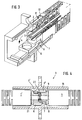
- a connector part 1 is shown, the connector housing 13 has a substantially approximately rectangular cross section.
- the plug pin 2 is held in a pin holder 10 which has an end part 9 which has a bore, the inner wall of which surrounds the plug pin.
- the actual connector housing 13 is axially displaceable on the pin holder 10 by a small distance.
- a locking bar 11 is arranged on each of two opposite sides, which is approximately at the same height as a ramp 20 belonging to the plug housing 13.
- a guide piece 8 is arranged on the cover 6 on one side.
- the guide piece has an approximately nose-like configuration here.
- FIG. 2 shows a socket part 3 for receiving the plug part 1.
- the socket part essentially has a hollow box-shaped socket housing 16 which is provided with a flange 14 for attachment to a housing wall.
- the actual socket 4 for receiving the plug pin or the plug pins is held in a socket holder 21.
- the socket is preferably held in a floating manner in the socket holder.
- resilient tongues 15 are arranged, at the end of which a pawl 12 is seated.
- a control track is provided on an inside of the socket housing, which here has the form of parallel guide links 7.
- the socket holder 21 is held in the socket housing 16 with the aid of a holding wall 22.
- the holding wall is dimensioned such that it leaves an opening 23, 23 'at the top and bottom, which extends over the entire width. These openings serve to receive the opened cover 6 of an inserted plug part 1, as subsequently is still described.
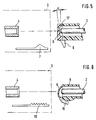
- the plug connection with the plug part inserted can be seen in FIG. 3.
- the guide piece 8 of the cover 6 hits the guide link 7, the cover 6 being folded down in the direction of arrow a.
- the actual plug socket 4 is not shown in FIG. 3.
- the plug pin 2 penetrates into the plug socket 4 in the course of the insertion movement, in which its end face 5 meets the end face of an adjacent plug pin.
- the pawl 12 engages behind the locking bar 11, as a result of which the plug part is secured in the socket part.
- the exemplary embodiment shown is a so-called push-and-pull lock.
- This latching device can only be released if the tensile force acts on the plug housing 13 to pull out the plug part.
- the connector housing 13 slides back somewhat relative to the pin holder 10, the ramp 20 lifting the pawl 12 so that the locking bar 11 is released (FIG. 1).
- the tensile force acts on the cable (not shown here) and thus on the pin holder 10, the pawl 12 cannot be disengaged.
- This type of locking on optical connectors is already known per se.
- the fixing of the plug part to the socket part could also in other ways, e.g. with the help of a union nut.
- the cover 6 is preferably made of plastic material and designed such that it can only be snapped into the end part 9.
- the lid 6 does not necessarily have to be pivoted back over the guide backdrop. It is readily conceivable that the closing movement only takes place by springback with the aid of a suitable spring element.
- FIG. 4 schematically shows a socket part 3 according to FIG. 2, into which a plug part 1, 1 'is inserted from both sides.
- this socket part not only has a pair of guide slots 7 on the underside, but also a pair of guide slots 7 'on the top, symmetrically offset with respect to the plane of contact between the two connector pins.
- the plug part 1 ' is inserted rotated by 180 ° relative to the plug part 1, the outer contour of the plug housing and the inner contour of the socket housing being designed such that the two plug parts can only be inserted in this position.
- the two covers 6 and 6 'of the plug parts 1 and 1' overlap in the inserted state and slide through the openings 23 and 23 'according to FIG. 2.
- Figure 5 shows again schematically a part of the socket 4 and the guide link 7 in the socket part 3 and the cover 6 with the guide piece 8.
- the cover is cap-shaped, the cover inner wall 17 is chamfered at an angle ⁇ relative to the plug end face in order to a feedback of Avoid light through reflection.
- the angle ⁇ can be, for example, approximately 7 °.
- the geometric relationship between the socket 4, the guide link 7 and the cover 6 must be selected such that the cover 6 is opened in good time before the socket 4 is reached becomes. The cover then partially slides under the socket 4.
- FIG. 6 An alternative embodiment of the invention is shown schematically in Figure 6.
- the control path here does not consist of a guide link, but of a rack section 18.
- the cover 6 is curved in an arcuate manner and is displaceably mounted on the circular part on the end part 9, for example in lateral grooves or the like.
- the cover has a toothed segment 19, which meshes with the toothed rack section 18 when the plug part is inserted into the socket part. The cover 6 is pushed open and the plug pin 2 is exposed before it reaches the socket 4.
- the lid closure according to the invention can not only be implemented on connector parts with a square cross section.
- Plug parts with a round cross section can also be provided in the same or similar manner with a movable cover, which is then also essentially round.
- the socket part does not necessarily have to be a separate component. It would be conceivable that the socket part is directly part of the one plug part.
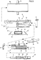
- FIGS. 7 to 12 show a further alternative exemplary embodiment of the invention, in which the cover performs a combined pivoting and sliding movement.
- the fastening and unlocking of the plug part in the socket part is also solved here.
- the same components have the same reference numerals as in the previous embodiments.
- FIGS. 7 and 8 show a plug part 1, which essentially also has an approximately rectangular plug housing 13.
- the pin holder with the connector pin 2 is not axially displaceable, but is held firmly in the connector housing.
- the connector housing also carries a locking bar 11, on which it can be latched in the socket part.
- An unlocking lever 25 serves for unlocking, the function of which will be explained in more detail below.
- the cover 6 has a guide piece 8 in the form of 2 wings running at right angles to the cover 6.
- Articulated cams 28 (FIG. 12) are arranged on the inside of these wings, which are not visible in the figure, and each engage in a guide slot 27 on the side wall of a prismatic guide strip 26.
- the slots 27 run upward in the area of the locking strips 11 so that the articulated cams can be inserted.
- Control cams 29 are arranged on the outside of the vanes 42 at a distance from the articulated cams 28. These control cams serve to move the cover 6 in the socket part with the aid of guide grooves 30 (FIG. 12).
- a spring cam 24 is arranged between the wings 42 and presses against the end face of the guide bar 26.
- FIG. 8 shows the plug part 1 with the cover 6 open.
- the cover 6 normally occupies this position only within the socket part. Of course, it is also possible to open the lid manually and push it back.
- the cover 6 performs a pivoting movement about the axes of the articulated cams 28 and at the same time the articulated cams slide in the guide slots 27 in the direction of arrow b backwards against the locking bar 11.
- the cover 6 is withdrawn behind the plane of the end face 5 of the plug pin 2.
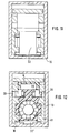
- FIG 9 shows the individual parts of a connector with the individual components and Figure 10 shows a cross section through such a connector.
- the socket part 3 is constructed in two parts and consists of the outer socket housing 16 with the flange 14 and the inner socket housing 41. As can be seen in particular from FIGS. 11 and 12, the socket part also has an essentially box-shaped cross section.
- the inner socket housing 41 can be inserted into the outer socket housing 16, whereby it is secured on both sides with a snap-on frame 31.
- the inner socket housing 41 is constructed approximately symmetrically and has lateral guide grooves 30 for receiving and guiding the control cams 29 on the guide piece of the cover.
- a resilient tongue 15 with a pawl 12 is provided to hold and secure the plug part.
- Lateral grooves 43 on the inner wall of the inner socket housing 41 can accommodate the side strips 44 on the plug housing 13. In this way, the plug part cannot be tilted in the socket part.
- the socket holder 21 with the actual socket 4 for the plug pins is inserted from below through an opening into the inner socket housing 41. After sliding the outer socket housing 16, the socket holder 21 is secured.
- a two-armed leaf spring 33 is also clamped beneath the socket holder 21 and pretensions a protective flap 32 with its free ends.
- the protective flap 32 is articulated between the inner socket housing 41 and the outer socket housing 16.
- the plug part 1 consists essentially of the plug housing 13, to which the cover 6 and the unlocking lever 25 are attached.
- the unlocking lever 25 is engaged with its articulated cams 35 in openings 45 in the plug housing 13.
- a lever arm 34 engages under the pawl 12 on the socket part so that it can be raised for unlocking.
- the inside of the plug housing 13 is partially designed as a spline hub 34.
- the pin holder 10 has a section which is designed as a spline shaft 36.
- Individual wedges 39 on a rear section of the pin holder snap into the shoulders 40 of the spline hub, so that the pin holder 10 can be pushed into the plug housing 13.
- the spline shaft / spline hub connection serves to determine the relative angular position of the connector pin. With six individual wedges or keyways, there are a total of six possible angular positions of the plug pin in the connector housing 13. With respect to the central axis of the optical waveguide, the most optimal position is selected in each case by a measurement process, so that the most favorable tolerance pair with respect to the eccentricity of the optical waveguide always meets within a plug connection.
- the pin holder 10 is preferably made in one piece from plastic material and has a resilient section 38, so that the plug pin 2 is axially cushioned relative to the plug housing 13.
- FIG. 10 shows the socket part 3 in the assembled state, which is fastened, for example, to a housing wall 46.
- a connector part 1 is already inserted and locked on the right-hand side, the cover 6 being arranged axially parallel between the guide strip 26 of the connector housing and the tongue 15 of the inner socket housing 41.
- the plug pin 2 penetrates into the socket 4. In this position, too Protective flap 32 pressed axially parallel downward against the force of the leaf spring 33.
- the front section of a connector part 1 is shown, which is inserted into the connector.
- the cover 6 is initially still in its closed position.
- the control cams 29 engage in the guide grooves 30, which is somewhat facilitated by a wedge-shaped extension.
- the guide grooves 30 have a path that first runs parallel to the axis, then obliquely against the central axis of the plug connection and then again runs parallel to the axis.
- the control cams 29 are pressed down, which initiates the pivoting movement of the cover 6.
- An intermediate position of the cover 6 in this oblique section is indicated by dash-dotted lines.
- the movement of the cover relative to the connector housing 13 is delayed, so that the cover 6 is pulled backwards.
- the protective flap 32 is also pressed down continuously in the course of the insertion movement until it assumes its end position.
- the pawl 12 engages behind the locking bar 11.
Abstract
Description
Die Erfindung betrifft eine Steckverbindung für Lichtwellenleiter gemäss dem Oberbegriff von Anspruch 1. Im Gegensatz zu elektrischen Steckverbindungen können bei optischen Steckverbindungen bereits geringe Verschmutzungen zu einer Übertragungsdämpfung führen, da Glasfasern mit kleinsten Querschnitten stirnseitig aufeinander ausgerichtet werden müssen. Es wurden daher bereits Schutzvorrichtungen vorgesehen, mit deren Hilfe der Steckerstift beim nicht eingesteckten Stecker geschützt werden kann.The invention relates to a plug-in connection for optical fibers according to the preamble of
Bisher wurden derartige Schutzvorrichtungen jedoch nur an relativ massiven Steckverbindungen für den feldmässigen Einsatz vorgesehen. Die EP-A-22 000 zeigt beispielsweise eine Schutzvorrichtung für einen Stecker, welcher auch für Lichtwellenleiter verwendet werden könnte. Das Grundprinzip der Schutzvorrichtung besteht darin, dass die Steckerstifte durch zwei übereinanderliegende Scheiben verdeckt sind. Die Scheiben sind auf einer gemeinsamen Achse relativ zueinander verdrehbar und mit Öffnungen versehen, welche in wenigstens einer Relativlage deckungsgleich übereinander liegen und auf diese Weise die Steckerstifte freigeben. Die Steckerstifte können dann in einer achsparallelen Bewegung durch die Öffnungen hindurch ausgefahren und in die Steckerbuchsen gesteckt werden. Der Nachteil dieser Schutzvorrichtung besteht darin, dass sie sich nur für schwere Steckerteile mit einem bestimmten Aussendurchmesser eignet. Zum Einstecken des Steckerteils muss sowohl eine Drehbewegung, als auch eine lineare Schiebebewegung ausgeführt werden. Für kleine Steckerteile, wie sie beispielsweise in der Messtechnik, in der Nachrichtentechnik oder in der Unterhaltungselektronik immer mehr Anwendung finden, ist die bekannte Vorrichtung nicht geeignet.So far, however, such protective devices have only been provided on relatively massive plug connections for field use. EP-A-22 000, for example, shows a protective device for a plug, which could also be used for optical fibers. The basic principle of the protective device is that the connector pins are covered by two superimposed disks. The disks can be rotated relative to one another on a common axis and are provided with openings which lie congruently one above the other in at least one relative position and in this way release the connector pins. The connector pins can then be moved through the openings in an axis-parallel movement and inserted into the connector sockets. The disadvantage of this protective device is that it is only suitable for heavy connector parts with a certain outside diameter. To insert the plug part, both a rotary movement and a linear sliding movement must be carried out. The known device is not suitable for small plug parts, such as are used more and more in measurement technology, in communications technology or in consumer electronics.
Es ist daher eine Aufgabe der Erfindung, eine Steckverbindung der eingangs genannten Art zu schaffen, die bei einfachstem konstruktivem Aufbau auch bei kleinformatigen Steckern den Steckerstift zuverlässig vor Verunreinigungen durch Staub, Fingerabdrücke, Spritzwasser usw. schützt und die zudem einfach zu handhaben ist. Diese Aufgabe wird erfindungsgemäss mit einer Steckverbindung gelöst, welche die Merkmale im Anspruch 1 bzw. im Anspruch 14 aufweist. Der beweglich am Steckerteil angeordnete Deckel ist ein einziges Bauteil, das durch eine einfache lineare Steckbewegung bewegt werden kann. Komplizierte Bewegungsabläufe zum Freilegen des Steckerstifts sind nicht erforderlich, sondern der Steckerstift wird unmittelbar im Verlauf der Einsteckbewegung freigelegt. Damit ist auch zuverlässig gewährleistet, dass der hochpräzise bearbeitete und relativ empfindliche Steckerstift erst freigegeben wird, wenn er sich bereits im schützenden Buchsenteil befindet. Damit wird unter anderem auch verhindert, dass beispielsweise aus dem Steckerstift austretendes Laserlicht unbeabsichtigt zu Augenschäden führen kann.It is therefore an object of the invention to provide a plug connection of the type mentioned, which reliably protects the plug pin against contamination by dust, fingerprints, splash water, etc., and which is also easy to handle, with the simplest structural design, even with small-format plugs. This object is achieved according to the invention with a plug connection which has the features in
Der Deckel ist vorzugsweise schwenkbar am Steckerteil gelagert und er weist ein Führungsstück auf, wobei die Steuerbahn wenigstens eine Führungskulisse ist, welche zum Schwenken des Deckels mit dem Führungsstück zusammenwirkt. Durch diese Massnahme kann der Deckel mit einem äussert geringen Kraftaufwand bewegt werden, der praktisch nicht grösser ist, als die ohnehin erforderliche Einsteckkraft.The cover is preferably pivotally mounted on the plug part and it has a guide piece, the control path being at least one guide link which cooperates with the guide piece to pivot the cover. As a result of this measure, the cover can be moved with an extremely low expenditure of force, which is practically no greater than the insertion force required anyway.
Alternativ kann der Deckel aber auch schwenkbar und verschiebbar am Steckerteil gelagert sein und er kann ein Führungsstück aufweisen, wobei die Steuerbahn wenigstens eine Führungsnut ist, welche zum Schwenken und Verschieben des Deckels mit dem Führungsstück zusammenwirkt. Diese kombinierte Schwenk-/Schiebebewegung des Deckels hat den Vorteil, dass der Deckel innerhalb des Buchsenteils platzsparend untergebracht werden kann. Anstelle einer Kreisbahn legt die Aussenkante des Deckels eine Kurvenbahn zurück, die wesentlich weniger Raum beansprucht.Alternatively, the cover can also be pivotally and displaceably mounted on the plug part and it can have a guide piece, the control track being at least one guide groove which interacts with the guide piece for pivoting and displacing the cover. This combined pivoting / sliding movement of the cover has the advantage that the cover can be accommodated in a space-saving manner within the socket part. Instead of a circular path, the outer edge back of the cover a curved path that takes up much less space.
Besonders einfach lässt sich die kombinierte Bewegung des Deckels realisieren, wenn das Führungsstück wenigstens ein Gelenkelement aufweist, das drehbar und verschiebbar in einen Führungsschlitz am Steckerteil eingreift und wenn es wenigstens ein Eingriffsglied aufweist, das bei geschlossenem Deckel in die Führungsnut am Buchsenteil eingreift. Gelenkelement und Eingriffsglied gewährleisten eine präzise Führung auch bei raschen Bewegungsabläufen. Das Führungsstück und die Führungsnut wirken vorteilhaft derart zusammen, dass der Deckel in der Öffnungsposition hinter die Ebene der Stirnseite des Steckerstifts zurückgezogen ist. Dies ermöglicht es, dass in ein Buchsenteil von beiden Seiten her die Stecker derart eingesteckt werden können, dass sich die geöffneten Deckel in der gleichen Ebene gegenüberliegen. Eine Verdrehung der Stecker um 180° zur Überlappung der Deckel ist nicht erforderlich.The combined movement of the cover can be implemented particularly easily if the guide piece has at least one joint element which rotatably and displaceably engages in a guide slot on the plug part and if it has at least one engagement member which engages in the guide groove on the socket part when the cover is closed. The joint element and the engaging link ensure precise guidance even with rapid movements. The guide piece and the guide groove advantageously cooperate in such a way that the cover is pulled back behind the plane of the end face of the plug pin in the open position. This makes it possible for the plug to be inserted into a socket part from both sides in such a way that the opened covers face each other in the same plane. It is not necessary to twist the connector by 180 ° to overlap the cover.
Der Deckel ist in der Öffnungsposition relativ zur Schliessposition vorzugsweise etwa um 90° verschwenkt. In dieser Position benötigt er relativ wenig Platz im Buchsenteil. Dies gilt namentlich für flächig ausgebildete Deckel. Andere Winkellagen in der Öffnungsposition wären jedoch denkbar.The cover is preferably pivoted about 90 ° in the open position relative to the closed position. In this position, it requires relatively little space in the socket part. This applies in particular to flat covers. However, other angular positions in the open position would be conceivable.
Der Deckel ist vorzugsweise unter Federvorspannung in die Schliessposition vorgespannt, so dass er bei ausgestecktem Steckerteil immer zuverlässig schliesst. Die Federvorspannung kann dabei auf ganz unterschiedliche Art und Weise erzeugt werden. Denkbar wäre eine auf der Schwenkachse gelagerte Schraubenfeder, ein Federbügel oder aber auch eine Lagerpfanne, welche derart ausgebildet ist, dass sie infolge der Materialelastizität eine Federwirkung in eine bestimmte Richtung ausübt.The cover is preferably biased into the closed position under spring tension so that it always closes reliably when the plug part is unplugged. The spring preload can be generated in very different ways. It would be conceivable for a helical spring mounted on the swivel axis, a spring clip or also a bearing socket which is designed such that it exerts a spring action in a certain direction due to the elasticity of the material.
Der Deckel kann auch mit einem Federnocken in die Schliessposition vorgespannt sein, der sich federnd gegen die Stirnseite und/oder gegen die Längsseite des Steckerteils presst. Ein derartiger Federnocken hat den Vorteil, dass er einstückig mit dem Deckel ausgebildet werden kann und dass daher für die Federvorspannung keine zusätzlichen Teile erforderlich sind.The cover can also be biased into the closed position with a spring cam which resiliently presses against the end face and / or against the long side of the plug part. Such a spring cam has the advantage that it can be formed in one piece with the cover and that therefore no additional parts are required for the spring preload.
Der Deckel kann im wesentlichen scheibenförmig ausgebildet oder aber auch bogenförmig gekrümmt sein. Im letzteren Fall ist es möglich, dass er auf einer Bogenbahn verschiebbar am Steckerteil gelagert ist.The cover can be essentially disc-shaped or can also be curved in an arc. In the latter case, it is possible for it to be slidably mounted on the plug part on an arc path.
Der Deckel kann sich entweder unmittelbar gegen die Stirnseite des Steckerstifts pressen oder er kann gegen ein den Steckerstift umgebendes Endteil pressbar sein. Besonders vorteilhaft ist die der Steckerstirnseite zugewandte Innenseite des Deckels wenigstens im Bereich des Steckerstifts derart relativ zur optischen Achse des Lichtwellenleiters im Steckerstift angeschrägt, dass eine Rückkoppelung von Licht in den Lichtwellenleiter verhindert wird.The cover can either press directly against the end face of the connector pin or it can be pressed against an end part surrounding the connector pin. The inside of the cover facing the plug end is at least in the area of the plug pin beveled relative to the optical axis of the optical waveguide in the plug pin such that feedback of light into the optical waveguide is prevented.
In der Regel wird die Steuerbahn aus Platzgründen vorzugsweise am Buchsenteil angeordnet sein. In bestimmten Fällen wäre aber auch die kinematische Umkehr dieses Prinzips ohne weiteres denkbar, so dass die Steuerbahn, beispielsweise eine Führungsnut oder eine Führungskulisse, am Deckel angeordnet ist, während am Buchsenteil ein Steuerelement, beispielsweise in der Form eines Steuernockens vorgesehen ist.As a rule, the control track will preferably be arranged on the socket part for reasons of space. In certain cases, however, the kinematic reversal of this principle would also be readily conceivable, so that the control track, for example a guide groove or a guide link, is arranged on the cover, while a control element, for example in the form of a control cam, is provided on the socket part.
Weitere Vorteile und Einzelmerkmale der Erfindung ergeben sich aus der nachfolgenden Beschreibung von Ausführungsbeispielen und aus den Zeichnungen. Es zeigen:
Figur 1- ein Steckerteil in perspektivischer Darstellung,
Figur 2- ein Buchsenteil für die Aufnahme des Steckerteils gemäss
Figur 1, Figur 3- das Steckerteil gemäss
Figur 1 im eingesteckten Zustand, jedoch ohne Buchse, Figur 4- einen Querschnitt durch das Buchsenteil gemäss
Figur 2 mit beidseitig eingesteckten Steckerteilen, Figur 5- eine schematische Prinzipdarstellung der Steckverbindung gemäss den
Figuren 1 bis 3, Figur 6- eine schematische Darstellung einer alternativen Steckverbindung,
Figur 7- ein alternatives Ausführungsbeispiel eines Steckerteils mit schwenkbarem und verschiebbarem Deckel in perspektivischer Darstellung bei geschlossenem Deckel,
Figur 8- das Steckerteil gemäss
Figur 7 bei geöffnetem Deckel, Figur 9- eine Steckverbindung mit vereinzelt dargestellten Bauteilen für das Steckerteil gemäss
Figur 7, Figur 10- die Steckverbindung gemäss
Figur 9 im zusammengebauten Zustand, bzw. beim Einschieben eines Steckerteils, Figur 11- einen Querschnitt durch die Ebene I-I gemäss
Figur 10 in vergrössertem Massstab, und Figur 12- einen Querschnitt durch die Ebene II-
II gemäss Figur 10 in vergrössertem Massstab.
- Figure 1
- a plug part in a perspective view,
- Figure 2
- a socket part for receiving the plug part according to Figure 1,
- Figure 3
- 1 in the inserted state, but without a socket,
- Figure 4
- 3 shows a cross section through the socket part according to FIG. 2 with plug parts inserted on both sides,
- Figure 5
- 2 shows a schematic basic illustration of the plug connection according to FIGS. 1 to 3,
- Figure 6
- a schematic representation of an alternative connector,
- Figure 7
- 3 shows an alternative exemplary embodiment of a plug part with a pivotable and displaceable cover in a perspective view with the cover closed,
- Figure 8
- 7 with the cover open,
- Figure 9
- 4 shows a plug connection with components shown individually for the plug part according to FIG. 7,
- Figure 10
- 9 in the assembled state or when inserting a plug part,
- Figure 11
- a cross section through the plane II according to Figure 10 on an enlarged scale, and
- Figure 12
- a cross section through the plane II-II according to Figure 10 on an enlarged scale.
In Figur 1 ist ein Steckerteil 1 dargestellt, dessen Steckergehäuse 13 einen im wesentlichen etwa rechteckigen Querschnitt aufweist. Der Steckerstift 2 ist in einer Stifthalterung 10 gehalten, welche ein Endteil 9 aufweist, das eine Bohrung aufweist, deren Innenwand den Steckerstift umgibt. Das eigentliche Steckergehäuse 13 ist auf der Stifthalterung 10 um eine kleine Strecke axial verschiebbar gelagert. An der Stifthalterung ist auf zwei sich gegenüberliegenden Seiten je eine Sperrleiste 11 angeordnet, welche etwa auf der gleichen Höhe liegt wie eine zum Steckergehäuse 13 gehörende Rampe 20.In Figure 1, a
An der Stirnseite des Endteils 9 ist verschwenkbar ein Deckel 6 gelagert, der etwa die gleiche Querschnittsfläche hat wie das Endteil 9. Auf einer Seite ist am Deckel 6 ein Führungsstück 8 angeordnet. Das Führungsstück hat hier eine etwa nasenartige Konfiguration.A
Figur 2 zeigt ein Buchsenteil 3 zur Aufnahme des Steckerteils 1. Das Buchsenteil hat im wesentlichen ein hohlkastenförmiges Buchsengehäuse 16, das mit einem Flansch 14 zur Befestigung an einer Gehäusewand versehen ist. Im innern des Buchsengehäuses ist die eigentliche Buchse 4 zur Aufnahme des Steckerstifts bzw. der Steckerstifte in einer Buchsenhalterung 21 gehalten. Vorzugsweise ist die Buchse schwimmend in der Buchsenhalterung gehalten. Am Buchsengehäuse 16 sind federnde Zungen 15 angeordnet, an deren Ende eine Sperrklinke 12 sitzt. Auf einer Innenseite des Buchsengehäuses ist eine Steuerbahn vorgesehen, welche hier die Form von parallelen Führungskulissen 7 aufweist.Figure 2 shows a
Die Buchsenhalterung 21 wird im Buchsengehäuse 16 mit Hilfe einer Haltewand 22 festgehalten. Die Haltewand ist so dimensioniert, dass sie oben und unten je eine Oeffnung 23, 23' freilässt, welche sich über die ganze Breite erstreckt. Diese Oeffnungen dienen dazu, den aufgeklappten Deckel 6 eines eingeschobenen Steckerteils 1 aufzunehmen, wie anschliessend noch beschrieben wird.The
Die Steckverbindung mit eingestecktem Steckerteil ist in Figur 3 ersichtlich. Beim Einführen des Steckerteils stösst das Führungsstück 8 des Deckels 6 auf die Führungskulisse 7, wobei der Deckel 6 in Pfeilrichtung a umgeklappt wird. Aus Gründen der besseren Übersichtlichkeit ist in Figur 3 die eigentliche Steckerbuchse 4 nicht dargestellt. Der Steckerstift 2 dringt jedoch im Verlauf der Einsteckbewegung in die Steckerbuchse 4 ein, in welcher seine Stirnseite 5 mit der Stirnseite eines benachbarten Steckerstifts zusammentrifft.The plug connection with the plug part inserted can be seen in FIG. 3. When inserting the plug part, the
Beim Erreichen der erforderlichen Einstecktiefe rastet die Sperrklinke 12 hinter die Sperrleiste 11 ein, wodurch das Steckerteil im Buchsenteil gesichert ist. Beim dargestellten Ausführungsbeispiel handelt es sich um eine sogenannte Push-and-Pull-Verriegelung. Diese Einrastvorrichtung kann nur gelöst werden, wenn die Zugkraft zum Herausziehen des Steckerteils am Steckergehäuse 13 angreift. Dabei gleitet das Steckergehäuse 13 relativ zur Stifthalterung 10 etwas zurück, wobei die Rampe 20 die Sperrklinke 12 anhebt, so dass die Sperrleiste 11 freigegeben wird (Fig. 1). Greift dagegen die Zugkraft am hier nicht dargestellten Kabel und damit an der Stifthalterung 10 an, so kann die Sperrklinke 12 nicht ausgerastet werden. Diese Art der Verriegelung an optischen Steckverbindungen ist an sich bereits bekannt. Selbstverständlich könnte die Fixierung des Steckerteils am Buchsenteil aber auch auf andere Weise, z.B. mit Hilfe einer Überwurfmutter erfolgen.When the required insertion depth is reached, the
Beim Herausziehen des Steckerteils aus dem Buchsenteil muss das Führungsstück 8 wiederum über die Führungskulisse 7 gleiten, wobei der Deckel 6 wiederum zurückgeschwenkt wird. Der Deckel 6 ist vorzugsweise aus Kunststoffmaterial hergestellt und derart ausgebildet, dass er lediglich in das Endteil 9 eingerastet werden kann. Der Deckel 6 muss nicht unbedingt über die Führungskulisse zurückgeschwenkt werden. Es ist ohne weiteres denkbar, dass die Schliessbewegung nur durch Rückfederung mit Hilfe eines geeigneten Federelements erfolgt.When pulling the plug part out of the socket part, the
Figur 4 zeigt schematisch ein Buchsenteil 3 gemäss Figur 2, in welches von beiden Seiten ein Steckerteil 1, 1' eingesteckt ist. Wie aus dieser Figur ersichtlich ist, weist dieses Buchsenteil nicht nur ein Führungskulissenpaar 7 auf der Unterseite auf, sondern auch noch ein Führungskulissenpaar 7' auf der Oberseite, und zwar bezogen auf die Berührungsebene zwischen den beiden Steckerstiften symmetrisch versetzt angeordnet. Das Steckerteil 1' wird gegenüber dem Steckerteil 1 um 180° verdreht eingesteckt, wobei die Aussenkontur der Steckergehäuse und die Innenkontur des Buchsengehäuses so ausgebildet sind, dass die beiden Steckerteile nur in dieser Lage eingesteckt werden können. Die beiden Deckel 6 und 6' der Steckerteile 1 und 1' überlappen sich im eingesteckten Zustand und schieben sich durch die Oeffnungen 23 und 23' gemäss Figur 2. Selbstverständlich müssen jedoch in das Buchsenteil 3 nicht unbedingt zwei identische Steckerteile eingeschoben werden. Es wäre ohne weiteres denkbar, dass auf einer Seite ein Steckerteil ohne Deckel eingesteckt wird, beispielsweise wenn dieses Steckerteil auf der Innenseite eines Gehäuses liegt und praktisch nie entfernt werden muss.FIG. 4 schematically shows a
Figur 5 zeigt nochmals schematisch einen Teil der Buchse 4 und der Führungskulisse 7 im Buchsenteil 3 sowie den Deckel 6 mit dem Führungsstück 8. Der Deckel ist kappenartig ausgebildet, wobei die Deckelinnenwand 17 relativ zur Steckerstirnseite unter einem Winkel α angeschrägt ist, um eine Rückkoppelung von Licht durch Spiegelung zu vermeiden. Der Winkel α kann beispielsweise etwa 7° betragen. Selbstverständlich muss die geometrische Beziehung zwischen der Buchse 4, der Führungskulisse 7 und dem Deckel 6 so gewählt werden, dass der Deckel 6 rechtzeitig vor dem Erreichen der Buchse 4 aufgeklappt wird. Der Deckel schiebt sich dann teilweise noch unter die Buchse 4.Figure 5 shows again schematically a part of the
Ein alternatives Ausführungsbeispiel der Erfindung ist schematisch in Figur 6 dargestellt. Die Steuerbahn besteht hier nicht aus einer Führungskulisse, sondern aus einem Zahnstangenabschnitt 18. Der Deckel 6 ist bogenförmig gekrümmt ausgebildet und auf einer Kreisbogenbahn verschiebbar am Endteil 9 gelagert, beispielsweise in seitlichen Nuten oder dergleichen. Anstelle eines Führungsstücks weist der Deckel ein Zahnsegment 19 auf, welches beim Einstecken des Steckerteils in das Buchsenteil mit dem Zahnstangenabschnitt 18 kämmt. Dabei wird der Deckel 6 aufgeschoben und der Steckerstift 2 wird freigelegt, bevor er die Buchse 4 erreicht.An alternative embodiment of the invention is shown schematically in Figure 6. The control path here does not consist of a guide link, but of a
Selbstverständlich kann der erfindungsgemässe Deckelverschluss nicht nur an Steckerteilen mit viereckigem Querschnitt realisiert werden. Auch Steckerteile mit rundem Querschnitt können auf gleiche oder auf ähnliche Weise mit einem beweglichen Deckel versehen werden, der dann ebenfalls im wesentlichen rund ausgebildet ist. Schliesslich braucht das Buchsenteil auch nicht unbedingt ein separates Bauteil zu sein. Es wäre denkbar, dass das Buchsenteil unmittelbar Bestandteil des einen Steckerteils ist.Of course, the lid closure according to the invention can not only be implemented on connector parts with a square cross section. Plug parts with a round cross section can also be provided in the same or similar manner with a movable cover, which is then also essentially round. After all, the socket part does not necessarily have to be a separate component. It would be conceivable that the socket part is directly part of the one plug part.
In den Figuren 7 bis 12 ist ein weiteres alternatives Ausführungsbeispiel der Erfindung dargestellt, bei dem der Deckel eine kombinierte Schwenk- und Schiebebewegung ausführt. Alternativ gelöst ist hier auch die Befestigung und Entriegelung des Steckerteils im Buchsenteil. Die gleichartigen Bauteile haben die gleichen Bezugszeichen wie bei den vorhergehenden Ausführungsbeispielen.FIGS. 7 to 12 show a further alternative exemplary embodiment of the invention, in which the cover performs a combined pivoting and sliding movement. Alternatively, the fastening and unlocking of the plug part in the socket part is also solved here. The same components have the same reference numerals as in the previous embodiments.
In den Figuren 7 und 8 ist zunächst ein Steckerteil 1 dargestellt, das im wesentlichen ebenfalls ein etwa rechteckiges Steckergehäuse 13 aufweist. Wie nachstehend noch ausgeführt wird, ist jedoch die Stifthalterung mit dem Steckerstift 2 nicht axial verschiebbar, sondern fest im Steckergehäuse gehalten. Das Steckergehäuse trägt jedoch ebenfalls eine Sperrleiste 11, an der es im Buchsenteil eingeklinkt werden kann. Zur Entriegelung dient ein Entriegelungshebel 25, dessen Funktion nachstehend noch etwas genauer erläutert wird.FIGS. 7 and 8 show a
Der Deckel 6 weist ein Führungsstück 8 in der Form von 2 rechtwinklig zum Deckel 6 verlaufenden Flügeln auf. Auf der Innenseite dieser Flügel - in der Abbildung hier nicht sichtbar - sind Gelenknocken 28 (Figur 12) angeordnet, welche je in einen Führungsschlitz 27 an der Seitenwand einer prismatischen Führungsleiste 26 eingreifen. Die Schlitze 27 laufen im Bereich der Sperrleisten 11 nach oben aus, damit die Gelenknocken eingeführt werden können. Auf der Aussenseite der Flügel 42 sind im Abstand zu den Gelenknocken 28 Steuernocken 29 angeordnet. Diese Steuernocken dienen dazu, den Deckel 6 mit Hilfe von Führungsnuten 30 (Figur 12) im Buchsenteil zu bewegen.The
Damit der Deckel 6 in der in Figur 7 dargestellten Schliessposition verbleibt, ist zwischen den Flügeln 42 ein Federnocken 24 angeordnet, der sich gegen die Stirnseite der Führungsleiste 26 presst.To ensure that the
Figur 8 zeigt das Steckerteil 1 bei geöffnetem Deckel 6. Diese Position nimmt der Deckel 6 normalerweise nur innerhalb des Buchsenteils ein. Selbstverständlich ist es jedoch möglich, den Deckel auch manuell aufzuklappen und zurückzuschieben. Der Deckel 6 führt dabei eine Schwenkbewegung um die Achsen der Gelenknocken 28 aus und gleichzeitig gleiten die Gelenknocken in den Führungsschlitzen 27 in Pfeilrichtung b nach hinten gegen die Sperrleiste 11. Der Deckel 6 wird dabei hinter die Ebene der Stirnseite 5 des Steckerstifts 2 zurückgezogen.FIG. 8 shows the
Figur 9 zeigt die Einzelteile einer Steckverbindung mit den Einzelbauteilen und Figur 10 zeigt einen Querschnitt durch eine deraritige Steckverbindung. Das Buchsenteil 3 ist zweiteilig aufgebaut und besteht aus dem äusseren Buchsengehäuse 16 mit dem Flansch 14 und aus dem inneren Buchsengehäuse 41. Wie insbesondere aus den Figuren 11 und 12 ersichtlich ist, hat auch das Buchsenteil einen im wesentlichen kastenförmigen Querschnitt. Das innere Buchsengehäuse 41 kann in das äussere Buchsengehäuse 16 eingeschoben werden, wobei es auf beiden Seiten mit einem aufschnappbaren Rahmen 31 gesichert wird. Das innere Buchsengehäuse 41 ist etwa symmetrisch aufgebaut und hat seitlich Führungsnuten 30 zur Aufnahme und Führung der Steuernocken 29 am Führungsstück des Deckels. Zum Festhalten und Sichern des Steckerteils ist je eine federnde Zunge 15 mit einer Sperrklinke 12 vorgesehen. Seitliche Nuten 43 an der Innenwand des inneren Buchsengehäuses 41 können die Seitenleisten 44 am Steckergehäuse 13 aufnehmen. Das Steckerteil kann auf diese Weise im Buchsenteil nicht verkantet werden.Figure 9 shows the individual parts of a connector with the individual components and Figure 10 shows a cross section through such a connector. The
Die Buchsenhalterung 21 mit der eigentlichen Buchse 4 für die Steckerstifte wird von unten her durch eine Öffnung in das innere Buchsengehäuse 41 eingeschoben. Nach dem Überschieben des äusseren Buchsengehäuses 16 ist die Buchsenhalterung 21 gesichert.The
Unterhalb der Buchsenhalterung 21 ist auch eine zweiarmige Blattfeder 33 eingeklemmt, die mit ihren freien Enden eine Schutzklappe 32 vorspannt. Wie insbesondere aus Figur 11 ersichtlich ist, ist die Schutzklappe 32 zwischen dem inneren Buchsengehäuse 41 und dem äusseren Buchsengehäuse 16 gelenkig gelagert. Diese Schutzklappen verhindern, dass aus einem einseitig eingesteckten Stecker Licht, insbesondere Laserlicht austreten kann.A two-
Das Steckerteil 1 besteht im wesentlichen aus dem Steckergehäuse 13, an welchem der Deckel 6 und der Entriegelungshebel 25 befestigt sind. Der Entriegelungshebel 25 ist mit seinen Gelenknocken 35 in Öffnungen 45 im Steckergehäuse 13 eingerastet. Ein Hebelarm 34 greift im eingesteckten Zustand unter die Sperrklinke 12 am Buchsenteil, so dass diese zur Entriegelung angehoben werden kann.The
Wie insbesondere auch aus Figur 12 hervorgeht, ist die Innenseite des Steckergehäuses 13 teilweise als Keilnabe 34 ausgebildet. Die Stifthalterung 10 weist einen Abschnitt auf, der als Keilwelle 36 ausgebildet ist. Einzelne Keile 39 an einem hinteren Abschnitt der Stifthalterung rasten an den Schultern 40 der Keilnabe ein, so dass die Stifthalterung 10 in das Steckergehäuse 13 eingeprellt werden kann. Die Keilwellen/Keilnabenverbindung dient dabei zur Festlegung der relativen Winkelposition des Steckerstifts. Bei sechs Einzelkeilen bzw. Keilnuten ergeben sich insgesamt sechs mögliche Winkelpositionen des Steckerstifts im Steckergehäuse 13. Bezogen auf die Mittelachse des Lichtwellenleiters wird jeweils durch einen Messvorgang die optimalste Position ausgewählt, so dass innerhalb einer Steckverbindung stets die günstigste Toleranzpaarung bezüglich der Exzentrizität des Lichtwellenleiters aufeinandertrifft.As can also be seen in particular from FIG. 12, the inside of the
Die Stifthalterung 10 ist vorzugsweise einstückig aus Kunststoffmaterial hergestellt und hat einen federnden Abschnitt 38, so dass der Steckerstift 2 relativ zum Steckergehäuse 13 axial abgefedert ist.The
Figur 10 zeigt das Buchsenteil 3 im zusammengebauten Zustand, das beispielsweise an einer Gehäusewand 46 befestigt ist. Auf der rechten Seite ist bereits ein Steckerteil 1 eingesteckt und verriegelt, wobei der Deckel 6 achsparallel zwischen der Führungsleiste 26 des Steckergehäuses und der Zunge 15 des inneren Buchsengehäuses 41 angeordnet ist. Der Steckerstift 2 dringt in die Buchse 4 ein. In dieser Stellung ist auch die Schutzklappe 32 gegen die Kraft der Blattfeder 33 achsparallel nach unten gepresst.FIG. 10 shows the
Auf der linken Seite der Steckverbindung ist der vordere Abschnitt eines Steckerteils 1 dargestellt, das in die Steckverbindung eingeschoben wird. Der Deckel 6 ist dabei zunächst noch in seiner Schliessstellung. Beim Einschieben des Steckerteils 1 in das Buchsenteil 3 greifen die Steuernocken 29 in die Führungsnuten 30, was durch eine keilförmige Erweiterung etwas erleichtert wird. Die Führungsnuten 30 haben einnen Bahnverlauf, der zunächst achsparallel, dann schräg gegen die Mittelachse der Steckverbindung und dann wieder achsparallel verläuft. Im schrägen Abschnitt werden die Steuernocken 29 nach unten gepresst, womit die Schwenkbewegung des Deckels 6 eingeleitet wird. Mit strichpunktierten Linien ist eine Zwischenstellung des Deckels 6 in diesem schrägen Abschnitt angedeutet. Gleichzeitig wird die Bewegung des Deckels relativ zum Steckergehäuse 13 verzögert, so dass der Deckel 6 nach hinten gezogen wird. Selbstverständlich wird im Verlauf der Einsteckbewegung auch die Schutzklappe 32 kontinuierlich nach unten gepresst, bis sie ihre Endstellung einnimmt. Sobald das Steckerteil 1 seine Endposition erreicht hat, in welcher die Stirnseiten der sich gegenüberliegenden Steckerstifte aneinander anliegen, rastet die Sperrklinke 12 hinter der Sperrleiste 11 ein.On the left side of the connector, the front section of a
Zum Herausziehen eines Steckerteils aus dem Buchsenteil muss lediglich der Entriegelungshebel 25 nach unten gepresst werden, wobei über den Hebelarm 34 die Sperrklinke 12 angehoben wird und damit die Sperrleiste 11 freigibt. Selbstverständlich könnte hier aber auch eine andere Entriegelung des Steckerteils, beispielsweise mit dem bereits eingangs beschriebenen Push-and-Pull System realisiert werden.To pull a plug part out of the socket part, only the unlocking
Claims (14)
Priority Applications (4)
| Application Number | Priority Date | Filing Date | Title |
|---|---|---|---|
| AU38490/93A AU658999B2 (en) | 1992-05-20 | 1993-05-10 | Plug connector for optical fibers |
| US08/059,359 US5348487A (en) | 1992-05-20 | 1993-05-11 | Plug connector for optical fibers |
| JP11852393A JP3258760B2 (en) | 1992-05-20 | 1993-05-20 | Plug connector for optical fiber |
| JP2001307209A JP3681672B2 (en) | 1992-05-20 | 2001-10-03 | Plug connector for optical fiber |
Applications Claiming Priority (2)
| Application Number | Priority Date | Filing Date | Title |
|---|---|---|---|
| CH162592 | 1992-05-20 | ||
| CH1625/92 | 1992-05-20 |
Publications (3)
| Publication Number | Publication Date |
|---|---|
| EP0570652A2 true EP0570652A2 (en) | 1993-11-24 |
| EP0570652A3 EP0570652A3 (en) | 1993-12-01 |
| EP0570652B1 EP0570652B1 (en) | 1996-04-03 |
Family
ID=4214821
Family Applications (1)
| Application Number | Title | Priority Date | Filing Date |
|---|---|---|---|
| EP92810963A Expired - Lifetime EP0570652B1 (en) | 1992-05-20 | 1992-12-08 | Connector for optical fibres |
Country Status (2)
| Country | Link |
|---|---|
| EP (1) | EP0570652B1 (en) |
| DE (1) | DE59205913D1 (en) |
Cited By (30)
| Publication number | Priority date | Publication date | Assignee | Title |
|---|---|---|---|---|
| EP0642044A1 (en) * | 1993-09-02 | 1995-03-08 | State of Israel Ministry of Defence Raphael Armament Development Authority | Line terminal particularly signal transmitting, connector assembly |
| EP0613030A3 (en) * | 1993-02-24 | 1995-06-21 | Sumitomo Wiring Systems | Optical fiber connector. |
| EP0665454A1 (en) * | 1994-02-01 | 1995-08-02 | Hirose Electric Co., Ltd. | Connector |
| EP0697607A1 (en) * | 1994-08-01 | 1996-02-21 | Molex Incorporated | Fiber optic component assembly with a movable protective shield |
| EP0823649A1 (en) * | 1996-08-08 | 1998-02-11 | Diamond S.A. | Connector part for optical connection |
| EP0893718A1 (en) * | 1997-07-21 | 1999-01-27 | Diamond SA | Receptacle in particular for an optical connector and connector for light guides |
| WO1998053347A3 (en) * | 1997-05-20 | 1999-04-01 | Adc Telecommunications Inc | Fiber connector and adapter |
| EP0962799A2 (en) * | 1998-06-05 | 1999-12-08 | Hirose Electric Co., Ltd. | Optical connector with shutter |
| EP1004911A1 (en) * | 1998-11-23 | 2000-05-31 | Diamond SA | Socket for an optical fibre plug |
| US6142676A (en) * | 1997-05-20 | 2000-11-07 | Adc Telecommunications, Inc. | Fiber connector and adaptor |
| EP1072919A1 (en) * | 1999-07-26 | 2001-01-31 | Diamond SA | Plug for optical connection |
| EP1072917A1 (en) * | 1999-07-26 | 2001-01-31 | Diamond SA | Connector with protection flap for optical connection |
| WO2002071122A1 (en) * | 2001-03-01 | 2002-09-12 | Huber+Suhner Ag | Fiber-optical connector system |
| EP1331499A1 (en) * | 2002-01-25 | 2003-07-30 | Diamond S.A. | Optical connector |
| WO2003104870A1 (en) * | 2002-06-06 | 2003-12-18 | Huber+Suhner Ag | Optical plug-in connection |
| DE19742932B4 (en) * | 1996-09-30 | 2005-02-10 | The Whitaker Corp., Wilmington | Adapter for fiber optic connector |
| DE102004009218A1 (en) * | 2004-02-26 | 2005-10-20 | Winter & Ibe Olympus | Coupling connection of a light conductor connection cable with an endoscope optic |
| EP1598685A1 (en) * | 2004-05-21 | 2005-11-23 | Neutrik Aktiengesellschaft | Device for an optical plug-in connection |
| US7283718B2 (en) | 2002-05-14 | 2007-10-16 | Huber+Suhner Ag | Optical connector with protective cover and leaf spring |
| EP1947493A1 (en) | 2007-01-16 | 2008-07-23 | Reichle & De-Massari AG | Connector system and protection device for optical connectors |
| DE102007053415A1 (en) | 2007-11-09 | 2009-05-14 | Robert Bosch Gmbh | Fiber optic connector system |
| US20110150396A1 (en) * | 2009-12-21 | 2011-06-23 | Hon Hai Precision Industry Co., Ltd. | Optical fiber connector |
| EP2362254A1 (en) * | 2010-02-22 | 2011-08-31 | Sanwa Denki Kogyo Co., Ltd. | Optical connector plug with shutter |
| CN102262270A (en) * | 2011-07-31 | 2011-11-30 | 中航光电科技股份有限公司 | Optical fibre connector plug with protective cover |
| EP2672301A1 (en) | 2012-06-07 | 2013-12-11 | Diamond SA | Connector |
| DE102013103173A1 (en) * | 2013-03-27 | 2014-10-02 | Reichle & De-Massari Ag | guard |
| EP3246737A1 (en) | 2016-05-18 | 2017-11-22 | Dätwyler Cabling Solutions AG | Coupling part for optical waveguide, and corresponding coupling method |
| EP3218968B1 (en) * | 2014-11-11 | 2020-06-10 | Huber+Suhner Ag | Connector assembly |
| CN113296193A (en) * | 2020-02-21 | 2021-08-24 | 立佳兴业股份有限公司 | Optical connector and optical connector module thereof |
| WO2023093272A1 (en) * | 2021-11-29 | 2023-06-01 | 宁德时代新能源科技股份有限公司 | First connector, battery, connector assembly, and electrical device |
Families Citing this family (6)
| Publication number | Priority date | Publication date | Assignee | Title |
|---|---|---|---|---|
| US6004147A (en) * | 1993-09-02 | 1999-12-21 | State Of Israel, Ministry Of Defence, Etc. | Line terminal particularly signal transmitter, connector assembly |
| EP1128199B8 (en) | 1998-07-27 | 2003-07-02 | Huber & Suhner Ag | Plug connection for light guides |
| DE19901447C2 (en) * | 1999-01-15 | 2001-03-22 | Tyco Electronics Logistics Ag | Connector for fiber optic cables |
| DE19919591C2 (en) * | 1999-04-29 | 2001-12-20 | Tyco Electronics Logistics Ag | Connector for fiber optic cables |
| US6422763B1 (en) | 2000-05-04 | 2002-07-23 | Delphi Technologies, Inc. | Fiber optic cable for connection to a mating connector |
| DE102013207510A1 (en) | 2013-04-25 | 2014-10-30 | Robert Bosch Gmbh | Electronic component |
Citations (6)
| Publication number | Priority date | Publication date | Assignee | Title |
|---|---|---|---|---|
| GB2112173A (en) * | 1981-12-21 | 1983-07-13 | Thomas & Betts Corp | Movable closure for optical elements |
| WO1985004493A1 (en) * | 1984-04-03 | 1985-10-10 | Thomas & Betts Corporation | Connection apparatus for optical fibers |
| EP0232792A1 (en) * | 1986-02-14 | 1987-08-19 | Hüls Troisdorf Aktiengesellschaft | Electrical coupler system |
| US4775327A (en) * | 1987-02-17 | 1988-10-04 | Amphenol Corporation | Connector with automatic protection cap |
| US4913514A (en) * | 1988-11-22 | 1990-04-03 | Advanced Optical Systems | Fiber optic connector |
| EP0462907A1 (en) * | 1990-06-21 | 1991-12-27 | RADIALL Société anonyme dite: | Optical fibre connector with rapid locking and unlocking |
-
1992
- 1992-12-08 DE DE59205913T patent/DE59205913D1/en not_active Expired - Lifetime
- 1992-12-08 EP EP92810963A patent/EP0570652B1/en not_active Expired - Lifetime
Patent Citations (6)
| Publication number | Priority date | Publication date | Assignee | Title |
|---|---|---|---|---|
| GB2112173A (en) * | 1981-12-21 | 1983-07-13 | Thomas & Betts Corp | Movable closure for optical elements |
| WO1985004493A1 (en) * | 1984-04-03 | 1985-10-10 | Thomas & Betts Corporation | Connection apparatus for optical fibers |
| EP0232792A1 (en) * | 1986-02-14 | 1987-08-19 | Hüls Troisdorf Aktiengesellschaft | Electrical coupler system |
| US4775327A (en) * | 1987-02-17 | 1988-10-04 | Amphenol Corporation | Connector with automatic protection cap |
| US4913514A (en) * | 1988-11-22 | 1990-04-03 | Advanced Optical Systems | Fiber optic connector |
| EP0462907A1 (en) * | 1990-06-21 | 1991-12-27 | RADIALL Société anonyme dite: | Optical fibre connector with rapid locking and unlocking |
Cited By (58)
| Publication number | Priority date | Publication date | Assignee | Title |
|---|---|---|---|---|
| EP0613030A3 (en) * | 1993-02-24 | 1995-06-21 | Sumitomo Wiring Systems | Optical fiber connector. |
| EP0642044A1 (en) * | 1993-09-02 | 1995-03-08 | State of Israel Ministry of Defence Raphael Armament Development Authority | Line terminal particularly signal transmitting, connector assembly |
| EP0665454A1 (en) * | 1994-02-01 | 1995-08-02 | Hirose Electric Co., Ltd. | Connector |
| EP0697607A1 (en) * | 1994-08-01 | 1996-02-21 | Molex Incorporated | Fiber optic component assembly with a movable protective shield |
| EP0823649A1 (en) * | 1996-08-08 | 1998-02-11 | Diamond S.A. | Connector part for optical connection |
| DE19742932B4 (en) * | 1996-09-30 | 2005-02-10 | The Whitaker Corp., Wilmington | Adapter for fiber optic connector |
| WO1998053347A3 (en) * | 1997-05-20 | 1999-04-01 | Adc Telecommunications Inc | Fiber connector and adapter |
| US7654749B2 (en) | 1997-05-20 | 2010-02-02 | Adc Telecommunications, Inc. | Fiber connector and adapter |
| US5984531A (en) * | 1997-05-20 | 1999-11-16 | Adc Telecommunications, Inc. | Fiber connector and adapter |
| KR100575911B1 (en) * | 1997-05-20 | 2006-05-02 | 에이디씨 텔레커뮤니케이션스 인코포레이티드 | Fiber connector and adapter |
| US7246950B2 (en) | 1997-05-20 | 2007-07-24 | Adc Telecommunications, Inc. | Fiber connector and adapter |
| US6076973A (en) * | 1997-05-20 | 2000-06-20 | Adc Telecommunications, Inc. | Fiber connector and adapter |
| US7384201B2 (en) | 1997-05-20 | 2008-06-10 | Adc Telecommunications, Inc. | Fiber connector and adapter |
| US6142676A (en) * | 1997-05-20 | 2000-11-07 | Adc Telecommunications, Inc. | Fiber connector and adaptor |
| US7503702B2 (en) | 1997-05-20 | 2009-03-17 | Adc Telecommunications, Inc. | Fiber connector and adapter |
| US9383524B2 (en) | 1997-05-20 | 2016-07-05 | Commscope Technologies Llc | Fiber connector and adapter |
| US6296398B1 (en) | 1997-05-20 | 2001-10-02 | Adc Telecommunications, Inc. | Fiber connector and adapter |
| US8870466B2 (en) | 1997-05-20 | 2014-10-28 | Adc Telecommunications, Inc. | Fiber connector and adapter |
| EP1331496A2 (en) * | 1997-05-20 | 2003-07-30 | ADC Telecommunications, Inc. | Fiber connector and adapter |
| US8186890B2 (en) | 1997-05-20 | 2012-05-29 | Adc Telecommunications, Inc. | Fiber connector and adapter |
| EP1331496A3 (en) * | 1997-05-20 | 2003-09-17 | ADC Telecommunications, Inc. | Fiber connector and adapter |
| US7874738B2 (en) | 1997-05-20 | 2011-01-25 | Adc Telecommunications, Inc. | Fiber connector and adapter |
| US7118288B2 (en) | 1997-05-20 | 2006-10-10 | Adc Telecommunications, Inc. | Fiber connector and adapter |
| US6910807B2 (en) | 1997-05-20 | 2005-06-28 | Adc Telecommunications, Inc. | Fiber connector and adapter |
| EP0893718A1 (en) * | 1997-07-21 | 1999-01-27 | Diamond SA | Receptacle in particular for an optical connector and connector for light guides |
| EP0893716A1 (en) * | 1997-07-21 | 1999-01-27 | Diamond S.A. | Receptacle in particular for an optical connector and connector for light guides |
| EP0962799A3 (en) * | 1998-06-05 | 2000-08-30 | Hirose Electric Co., Ltd. | Optical connector with shutter |
| EP0962799A2 (en) * | 1998-06-05 | 1999-12-08 | Hirose Electric Co., Ltd. | Optical connector with shutter |
| EP1004911A1 (en) * | 1998-11-23 | 2000-05-31 | Diamond SA | Socket for an optical fibre plug |
| EP1072919A1 (en) * | 1999-07-26 | 2001-01-31 | Diamond SA | Plug for optical connection |
| EP1072917A1 (en) * | 1999-07-26 | 2001-01-31 | Diamond SA | Connector with protection flap for optical connection |
| US6821023B2 (en) | 2001-03-01 | 2004-11-23 | Huber+Suhner Ag | Fiber-optical connector system |
| WO2002071122A1 (en) * | 2001-03-01 | 2002-09-12 | Huber+Suhner Ag | Fiber-optical connector system |
| EP1331499A1 (en) * | 2002-01-25 | 2003-07-30 | Diamond S.A. | Optical connector |
| US7283718B2 (en) | 2002-05-14 | 2007-10-16 | Huber+Suhner Ag | Optical connector with protective cover and leaf spring |
| US7255485B2 (en) | 2002-06-06 | 2007-08-14 | Huber+Suhner Ag | Optical plug-in connection |
| WO2003104870A1 (en) * | 2002-06-06 | 2003-12-18 | Huber+Suhner Ag | Optical plug-in connection |
| DE102004009218B4 (en) * | 2004-02-26 | 2006-03-09 | Olympus Winter & Ibe Gmbh | Coupling connection of a light conductor connection cable with an endoscope optic |
| DE102004009218A1 (en) * | 2004-02-26 | 2005-10-20 | Winter & Ibe Olympus | Coupling connection of a light conductor connection cable with an endoscope optic |
| EP1598685A1 (en) * | 2004-05-21 | 2005-11-23 | Neutrik Aktiengesellschaft | Device for an optical plug-in connection |
| EP1777562A1 (en) * | 2004-05-21 | 2007-04-25 | Neutrik Aktiengesellschaft | Device for an optical plug connector |
| EP1947493A1 (en) | 2007-01-16 | 2008-07-23 | Reichle & De-Massari AG | Connector system and protection device for optical connectors |
| DE102007053415A1 (en) | 2007-11-09 | 2009-05-14 | Robert Bosch Gmbh | Fiber optic connector system |
| US8858094B2 (en) | 2007-11-09 | 2014-10-14 | Robert Bosch Gmbh | Fiber optic connector system |
| US8240924B2 (en) * | 2009-12-21 | 2012-08-14 | Hon Hai Precision Industry Co., Ltd. | Optical fiber connector |
| US20110150396A1 (en) * | 2009-12-21 | 2011-06-23 | Hon Hai Precision Industry Co., Ltd. | Optical fiber connector |
| EP2362254A1 (en) * | 2010-02-22 | 2011-08-31 | Sanwa Denki Kogyo Co., Ltd. | Optical connector plug with shutter |
| CN102262270A (en) * | 2011-07-31 | 2011-11-30 | 中航光电科技股份有限公司 | Optical fibre connector plug with protective cover |
| WO2013182476A2 (en) | 2012-06-07 | 2013-12-12 | Diamond Sa | Plug-in connection |
| WO2013182476A3 (en) * | 2012-06-07 | 2014-01-30 | Diamond Sa | Plug-in connection |
| EP2672301A1 (en) | 2012-06-07 | 2013-12-11 | Diamond SA | Connector |
| US9632257B2 (en) | 2012-06-07 | 2017-04-25 | Diamond Sa | Plug-in connection |
| DE102013103173A1 (en) * | 2013-03-27 | 2014-10-02 | Reichle & De-Massari Ag | guard |
| EP3218968B1 (en) * | 2014-11-11 | 2020-06-10 | Huber+Suhner Ag | Connector assembly |
| EP3246737A1 (en) | 2016-05-18 | 2017-11-22 | Dätwyler Cabling Solutions AG | Coupling part for optical waveguide, and corresponding coupling method |
| DE102016006141A1 (en) * | 2016-05-18 | 2017-11-23 | Dätwyler Cabling Solutions Ag | Coupling part for optical waveguides and associated coupling method |
| CN113296193A (en) * | 2020-02-21 | 2021-08-24 | 立佳兴业股份有限公司 | Optical connector and optical connector module thereof |
| WO2023093272A1 (en) * | 2021-11-29 | 2023-06-01 | 宁德时代新能源科技股份有限公司 | First connector, battery, connector assembly, and electrical device |
Also Published As
| Publication number | Publication date |
|---|---|
| EP0570652B1 (en) | 1996-04-03 |
| DE59205913D1 (en) | 1996-05-09 |
| EP0570652A3 (en) | 1993-12-01 |
Similar Documents
| Publication | Publication Date | Title |
|---|---|---|
| EP0570652B1 (en) | Connector for optical fibres | |
| EP0599784B1 (en) | Socket for a fibre optic connection terminal | |
| EP0616236B1 (en) | Connector for a lightguide | |
| EP2288951B1 (en) | Termination box for glass fiber cables, and panel | |
| EP1509797A1 (en) | Optical plug-in connection | |
| DE60221944T2 (en) | Connector with coupling device | |
| EP1271204A1 (en) | Socket and plug for an optical connector | |
| EP2130609B1 (en) | Discharge device for media | |
| DE3645179C3 (en) | Electrical connector assembly with a control surface system | |
| DE10103187B4 (en) | Electrical terminal | |
| EP0893718A1 (en) | Receptacle in particular for an optical connector and connector for light guides | |
| DE4019981C2 (en) | Locking arrangement for doors | |
| WO2002071122A1 (en) | Fiber-optical connector system | |
| EP1504296B1 (en) | Optical connector | |
| DE19516241A1 (en) | Optical fiber connector | |
| DE10230465B3 (en) | Electrical connector | |
| DE102019200066A1 (en) | Hatch arrangement for a recreational vehicle | |
| EP1072918B1 (en) | Connector part for optical connection | |
| DE102005046458B4 (en) | Protective cap for receiving a connector | |
| DE19712645C1 (en) | Coupling between two optical devices | |
| DE3543989C2 (en) | ||
| DE3118990C2 (en) | Coupling device for an eyepiece | |
| DE2907888C2 (en) | Multipole connector | |
| DE102010054462A1 (en) | Electrical contact unit of electrical connector for charging cable of electric vehicle, has friction elements movable between blocking and release positions such that frictional connection with counter contact unit is blockable | |
| DE102022123964A1 (en) | hinge |
Legal Events
| Date | Code | Title | Description |
|---|---|---|---|
| PUAI | Public reference made under article 153(3) epc to a published international application that has entered the european phase |
Free format text: ORIGINAL CODE: 0009012 |
|
| PUAL | Search report despatched |
Free format text: ORIGINAL CODE: 0009013 |
|
| AK | Designated contracting states |
Kind code of ref document: A2 Designated state(s): AT BE CH DE DK ES FR GB GR IE IT LI LU MC NL PT SE |
|
| AK | Designated contracting states |
Kind code of ref document: A3 Designated state(s): AT BE CH DE DK ES FR GB GR IE IT LI LU MC NL PT SE |
|
| RBV | Designated contracting states (corrected) |
Designated state(s): CH DE FR GB IT LI NL |
|
| 17P | Request for examination filed |
Effective date: 19940110 |
|
| 17Q | First examination report despatched |
Effective date: 19950810 |
|
| GRAA | (expected) grant |
Free format text: ORIGINAL CODE: 0009210 |
|
| AK | Designated contracting states |
Kind code of ref document: B1 Designated state(s): CH DE FR GB IT LI NL |
|
| REG | Reference to a national code |
Ref country code: CH Ref legal event code: NV Representative=s name: HEPP, WENGER & RYFFEL AG |
|
| REF | Corresponds to: |
Ref document number: 59205913 Country of ref document: DE Date of ref document: 19960509 |
|
| ET | Fr: translation filed | ||
| ITF | It: translation for a ep patent filed |
Owner name: LENZI & C. |
|
| GBT | Gb: translation of ep patent filed (gb section 77(6)(a)/1977) |
Effective date: 19960613 |
|
| GRAH | Despatch of communication of intention to grant a patent |
Free format text: ORIGINAL CODE: EPIDOS IGRA |
|
| PLBE | No opposition filed within time limit |
Free format text: ORIGINAL CODE: 0009261 |
|
| STAA | Information on the status of an ep patent application or granted ep patent |
Free format text: STATUS: NO OPPOSITION FILED WITHIN TIME LIMIT |
|
| 26N | No opposition filed | ||
| REG | Reference to a national code |
Ref country code: GB Ref legal event code: IF02 |
|
| PGFP | Annual fee paid to national office [announced via postgrant information from national office to epo] |
Ref country code: GB Payment date: 20101208 Year of fee payment: 19 Ref country code: IT Payment date: 20101215 Year of fee payment: 19 |
|
| PGFP | Annual fee paid to national office [announced via postgrant information from national office to epo] |
Ref country code: DE Payment date: 20101130 Year of fee payment: 19 |
|
| PGFP | Annual fee paid to national office [announced via postgrant information from national office to epo] |
Ref country code: FR Payment date: 20111219 Year of fee payment: 20 Ref country code: NL Payment date: 20111220 Year of fee payment: 20 |
|
| PGFP | Annual fee paid to national office [announced via postgrant information from national office to epo] |
Ref country code: CH Payment date: 20120228 Year of fee payment: 20 |
|
| REG | Reference to a national code |
Ref country code: DE Ref legal event code: R071 Ref document number: 59205913 Country of ref document: DE |
|
| REG | Reference to a national code |
Ref country code: DE Ref legal event code: R071 Ref document number: 59205913 Country of ref document: DE |
|
| REG | Reference to a national code |
Ref country code: NL Ref legal event code: V4 Effective date: 20121208 |
|
| REG | Reference to a national code |
Ref country code: CH Ref legal event code: PL |
|
| REG | Reference to a national code |
Ref country code: GB Ref legal event code: PE20 Expiry date: 20121207 |
|
| PG25 | Lapsed in a contracting state [announced via postgrant information from national office to epo] |
Ref country code: GB Free format text: LAPSE BECAUSE OF EXPIRATION OF PROTECTION Effective date: 20121207 |