EP0571111A1 - Tubular assembly - Google Patents
Tubular assembly Download PDFInfo
- Publication number
- EP0571111A1 EP0571111A1 EP93303575A EP93303575A EP0571111A1 EP 0571111 A1 EP0571111 A1 EP 0571111A1 EP 93303575 A EP93303575 A EP 93303575A EP 93303575 A EP93303575 A EP 93303575A EP 0571111 A1 EP0571111 A1 EP 0571111A1
- Authority
- EP
- European Patent Office
- Prior art keywords
- tube
- cross sectional
- inside surface
- section
- partially
- Prior art date
- Legal status (The legal status is an assumption and is not a legal conclusion. Google has not performed a legal analysis and makes no representation as to the accuracy of the status listed.)
- Granted
Links
Images

Classifications
-
- A—HUMAN NECESSITIES
- A61—MEDICAL OR VETERINARY SCIENCE; HYGIENE
- A61B—DIAGNOSIS; SURGERY; IDENTIFICATION
- A61B5/00—Measuring for diagnostic purposes; Identification of persons
- A61B5/145—Measuring characteristics of blood in vivo, e.g. gas concentration, pH value; Measuring characteristics of body fluids or tissues, e.g. interstitial fluid, cerebral tissue
- A61B5/14542—Measuring characteristics of blood in vivo, e.g. gas concentration, pH value; Measuring characteristics of body fluids or tissues, e.g. interstitial fluid, cerebral tissue for measuring blood gases
-
- A—HUMAN NECESSITIES
- A61—MEDICAL OR VETERINARY SCIENCE; HYGIENE
- A61B—DIAGNOSIS; SURGERY; IDENTIFICATION
- A61B5/00—Measuring for diagnostic purposes; Identification of persons
- A61B5/145—Measuring characteristics of blood in vivo, e.g. gas concentration, pH value; Measuring characteristics of body fluids or tissues, e.g. interstitial fluid, cerebral tissue
- A61B5/1468—Measuring characteristics of blood in vivo, e.g. gas concentration, pH value; Measuring characteristics of body fluids or tissues, e.g. interstitial fluid, cerebral tissue using chemical or electrochemical methods, e.g. by polarographic means
- A61B5/1473—Measuring characteristics of blood in vivo, e.g. gas concentration, pH value; Measuring characteristics of body fluids or tissues, e.g. interstitial fluid, cerebral tissue using chemical or electrochemical methods, e.g. by polarographic means invasive, e.g. introduced into the body by a catheter
-
- B—PERFORMING OPERATIONS; TRANSPORTING
- B29—WORKING OF PLASTICS; WORKING OF SUBSTANCES IN A PLASTIC STATE IN GENERAL
- B29C—SHAPING OR JOINING OF PLASTICS; SHAPING OF MATERIAL IN A PLASTIC STATE, NOT OTHERWISE PROVIDED FOR; AFTER-TREATMENT OF THE SHAPED PRODUCTS, e.g. REPAIRING
- B29C61/00—Shaping by liberation of internal stresses; Making preforms having internal stresses; Apparatus therefor
- B29C61/04—Thermal expansion
-
- B—PERFORMING OPERATIONS; TRANSPORTING
- B29—WORKING OF PLASTICS; WORKING OF SUBSTANCES IN A PLASTIC STATE IN GENERAL
- B29C—SHAPING OR JOINING OF PLASTICS; SHAPING OF MATERIAL IN A PLASTIC STATE, NOT OTHERWISE PROVIDED FOR; AFTER-TREATMENT OF THE SHAPED PRODUCTS, e.g. REPAIRING
- B29C65/00—Joining or sealing of preformed parts, e.g. welding of plastics materials; Apparatus therefor
- B29C65/66—Joining or sealing of preformed parts, e.g. welding of plastics materials; Apparatus therefor by liberation of internal stresses, e.g. shrinking of one of the parts to be joined
-
- B—PERFORMING OPERATIONS; TRANSPORTING
- B29—WORKING OF PLASTICS; WORKING OF SUBSTANCES IN A PLASTIC STATE IN GENERAL
- B29C—SHAPING OR JOINING OF PLASTICS; SHAPING OF MATERIAL IN A PLASTIC STATE, NOT OTHERWISE PROVIDED FOR; AFTER-TREATMENT OF THE SHAPED PRODUCTS, e.g. REPAIRING
- B29C66/00—General aspects of processes or apparatus for joining preformed parts
- B29C66/01—General aspects dealing with the joint area or with the area to be joined
- B29C66/05—Particular design of joint configurations
- B29C66/10—Particular design of joint configurations particular design of the joint cross-sections
- B29C66/11—Joint cross-sections comprising a single joint-segment, i.e. one of the parts to be joined comprising a single joint-segment in the joint cross-section
- B29C66/112—Single lapped joints
- B29C66/1122—Single lap to lap joints, i.e. overlap joints
-
- B—PERFORMING OPERATIONS; TRANSPORTING
- B29—WORKING OF PLASTICS; WORKING OF SUBSTANCES IN A PLASTIC STATE IN GENERAL
- B29C—SHAPING OR JOINING OF PLASTICS; SHAPING OF MATERIAL IN A PLASTIC STATE, NOT OTHERWISE PROVIDED FOR; AFTER-TREATMENT OF THE SHAPED PRODUCTS, e.g. REPAIRING
- B29C66/00—General aspects of processes or apparatus for joining preformed parts
- B29C66/50—General aspects of joining tubular articles; General aspects of joining long products, i.e. bars or profiled elements; General aspects of joining single elements to tubular articles, hollow articles or bars; General aspects of joining several hollow-preforms to form hollow or tubular articles
- B29C66/51—Joining tubular articles, profiled elements or bars; Joining single elements to tubular articles, hollow articles or bars; Joining several hollow-preforms to form hollow or tubular articles
- B29C66/52—Joining tubular articles, bars or profiled elements
-
- B—PERFORMING OPERATIONS; TRANSPORTING
- B29—WORKING OF PLASTICS; WORKING OF SUBSTANCES IN A PLASTIC STATE IN GENERAL
- B29C—SHAPING OR JOINING OF PLASTICS; SHAPING OF MATERIAL IN A PLASTIC STATE, NOT OTHERWISE PROVIDED FOR; AFTER-TREATMENT OF THE SHAPED PRODUCTS, e.g. REPAIRING
- B29C66/00—General aspects of processes or apparatus for joining preformed parts
- B29C66/90—Measuring or controlling the joining process
- B29C66/91—Measuring or controlling the joining process by measuring or controlling the temperature, the heat or the thermal flux
- B29C66/914—Measuring or controlling the joining process by measuring or controlling the temperature, the heat or the thermal flux by controlling or regulating the temperature, the heat or the thermal flux
- B29C66/9141—Measuring or controlling the joining process by measuring or controlling the temperature, the heat or the thermal flux by controlling or regulating the temperature, the heat or the thermal flux by controlling or regulating the temperature
- B29C66/91411—Measuring or controlling the joining process by measuring or controlling the temperature, the heat or the thermal flux by controlling or regulating the temperature, the heat or the thermal flux by controlling or regulating the temperature of the parts to be joined, e.g. the joining process taking the temperature of the parts to be joined into account
-
- B—PERFORMING OPERATIONS; TRANSPORTING
- B29—WORKING OF PLASTICS; WORKING OF SUBSTANCES IN A PLASTIC STATE IN GENERAL
- B29L—INDEXING SCHEME ASSOCIATED WITH SUBCLASS B29C, RELATING TO PARTICULAR ARTICLES
- B29L2031/00—Other particular articles
- B29L2031/753—Medical equipment; Accessories therefor
- B29L2031/7542—Catheters
-
- Y—GENERAL TAGGING OF NEW TECHNOLOGICAL DEVELOPMENTS; GENERAL TAGGING OF CROSS-SECTIONAL TECHNOLOGIES SPANNING OVER SEVERAL SECTIONS OF THE IPC; TECHNICAL SUBJECTS COVERED BY FORMER USPC CROSS-REFERENCE ART COLLECTIONS [XRACs] AND DIGESTS
- Y10—TECHNICAL SUBJECTS COVERED BY FORMER USPC
- Y10S—TECHNICAL SUBJECTS COVERED BY FORMER USPC CROSS-REFERENCE ART COLLECTIONS [XRACs] AND DIGESTS
- Y10S174/00—Electricity: conductors and insulators
- Y10S174/08—Shrinkable tubes
-
- Y—GENERAL TAGGING OF NEW TECHNOLOGICAL DEVELOPMENTS; GENERAL TAGGING OF CROSS-SECTIONAL TECHNOLOGIES SPANNING OVER SEVERAL SECTIONS OF THE IPC; TECHNICAL SUBJECTS COVERED BY FORMER USPC CROSS-REFERENCE ART COLLECTIONS [XRACs] AND DIGESTS
- Y10—TECHNICAL SUBJECTS COVERED BY FORMER USPC
- Y10T—TECHNICAL SUBJECTS COVERED BY FORMER US CLASSIFICATION
- Y10T403/00—Joints and connections
- Y10T403/48—Shrunk fit
Definitions
- This invention relates to a tubular assembly, a method for the assembly thereof, and an apparatus for carrying out the method. More particularly, the invention is concerned with a tubular assembly comprising a tube and a part located at least partially within the tube.
- the part is preferably made of a thermoplastic polymer and relaxation of residual stresses or release of the memory of the manufacturing process used to make the part allows expansion of the part so that it engages the inside surface of the tube.
- tubes are stoppered, plugged or sealed by application of a press fit, shrink fit or wedging component into the bore thereof.
- Chemicals such as adhesives, sealants or glues are frequently applied to make a fluid tight joint.
- the accurate application of chemicals to make a small joint fluid tight presents added difficulties of placement and clean up. Often the chemicals used may interfere with the operation of the assembly being made therewith, and also chemical may leach into the blood stream during use of a tubular probe.
- Optical fibers or fiber optic chemical sensors used in vivo as probes must be sensitive to slight changes in gas or ion concentrations.
- U.S. patent No. 4,200,110 discloses a fiber optic pH probe comprising an ion permeable membrane envelope about the distal ends of a pair of optical fibers. The probe operates on the concept of optically detecting the change in color of a pH sensitive dye.
- U.S. Patent Reissue 31,879 discloses a method for measuring concentration of an analyte in a sample by measuring the intensity of light emitted from a fluorescent indicator attached to an optical fiber.
- U.S. Patent No. 5.047,208 discloses a calorimetric fiber optic sensor for blood gas measurement comprising a pH sensitive dye in a chamber at the distal end of an optical fiber. A white reflective surface is located distal to the chamber.
- U.S. Patent No. 5,005,576 discloses an optical probe for invasive blood gas measurement comprising sensors capable of measuring pH, pO2 and pCO2 using absorption dyes.
- a reflector unit is positioned at the distal end of an outer sheath having a gas-permeable adhesive to close off the end of the probe.
- U.S. Patent No. 5,047,627 discloses a multi-analyte sensor comprising three optical fibers each associated with an indicator matrix and a light reflectance material. Certainty and consistency of assembly is not always repeatable with adhesive attachment, and chemicals in the adhesive may adversely influence the chemistry of the sensor and therefor measurement accuracy.
- U.S. Patent No. 4,889,407 discloses an optical waveguide sensor having a plurality of cells arranged in an array which substantially covers the cross sectional area of the waveguide. Each of the cells contains an indicator sensitive to an analyte in a medium, particularly for the determination of pH and pCO2 in vivo in blood.
- a tubular assembly comprising a hollow elongated tube having an internal cross section with an inside surface, a proximal end and a distal end defining a bore around a longitudinal axis, and a part mounted within the bore so that it is at least partially within the tube, the part, preferably made of a thermoplastic polymer, having been thermally treated to expand and engage the inside surface of the tube so that, after change in temperature, the part has an external cross sectional size identical to the internal cross sectional size of the tube and thereby forms a fluid tight seal.
- the tube preferably has an internal cross sectional shape identical to the part and a cross sectional shape identical to the part and a cross sectional size larger than the part prior to changing temperature.
- the part has an external cross sectional size identical to the internal cross sectional size of the tube after change in temperature.
- the tube has a substantially circular internal cross sectional shape defined by the bore through the tube and the part has a substantially circular external cross sectional shape of a diameter that allows axial movement within the tube before thermal treatment.
- the part should preferably have a cross sectional shape and size to be near the inside surface upon placement of the part at least partially within the tube.
- the part or the tube may be supported so that relative movement along the axis places the part at least partially within the tube.
- the part is preferably made of a thermoplastic polymer by a process which develops within the polymer a memory of the unshaped thermoplastic polymer prior to forming into the cross sectional shape of the part so that residual stresses remaining in the formed part are relaxed by changing temperature causing expansion of the cross sectional size of the tube and/or the part.
- the part and tube are preferably made by an extrusion process to develop memory.
- the part may be located in the tube between the ends thereof or located in the tube near the proximal or distal end thereof.
- a form preferably made of a relatively nonconductive material, is preferably positioned for relative movement along the axis for placement about the tube whereinside the part is located.
- the form is preferably shaped and sized to fit the tube outside surface and contain it.
- the form, the tube and the part are preferably substantially circular in cross section.
- a heater preferably made of an electrically resistive element, is wrapped about the form and is associated therewith for changing the temperature of the tube and the part sufficiently to relax residual stresses of their respective manufacturing processes, and thereby cause engagement of the inside surface of the tube and the part.
- the heater changes the temperature beyond the glass transition point of the polymer allowing the combined tube and part to expand to the identical cross sectional size of the internal cross section of the form and to remain expanded thereafter.
- engagement means that if the part and tube are made of materials that are heat sealable with respect to one another, then they will fuse together when they are thermally heated. Alternatively, if the materials will not fuse then they form a tight fit therebetween upon engagement.
- the invention also provides a method of assembly of a tube with an axis along the longitude thereof and with inside and outside surfaces, a proximal end and a distal end and a part with a cross sectional shape and size similar to the inside surface of the tube when the part is at least partially within the tube using a form shaped and sized to fit about the outside surface of the tube and a heater associated with the form, which comprises the steps of supporting the tube and the part so that relative movement along the tube axis places the part at least partially within the tube; positioning the form for relative movement along the axis for placement about the tube whereinside the part is located to thereby contain the outside surface of the tube; subjecting the tube and the part to thermal treatment to change the temperature sufficiently to relax residual stresses and thereby cause engagement of the inside surface of the tube and the part.
- the method preferably also includes the added steps of clearing fluid about the junction between the part and the tube before heating. Preferably sufficient heat is conducted through the form into the part to form a seal between the part and the inside surface of the tube.
- the step of clearing fluid is performed most preferably by applying a vacuum near the part during placement.
- the invention also provides an apparatus for assembling a tube and a part inserted at least partially therewithin, characterized by a hollow elongated tube with an axis along the longitude thereof, and with inside and outside surfaces, a proximal end and a distal end; a part with a cross sectional shape and size similar to the inside surface when the part is at least partially within the tube, the part and the tube being supported so that relative movement along the axis places the part at least partially within the tube; a form positioned for relative movement along the axis for placement about the tube whereinside the part is located, the form shaped and sized to fit the tube outside surface and contain it; and a heater associated with the form for providing thermal treatment to change the temperature of the tube and the part sufficiently to relax residual stresses and thereby permit engagement between the inside surface of the tube and the part.
- the embodiment illustrated in Figure 1 comprises an apparatus 10 for assembly of a tube 11 and a part 12 located at least partially within the tube 11 by relaxation of residual stresses or release of the memory of the manufacturing process used to make the part 12 by a method which allows engagement of the tube 11 and the part 12.
- the most preferred application of the tubular assembly of the present invention is for the construction of a small (less than 20 gauge) blood gas sensor catheter.
- the assembly involves sealing of the distal portion of blood gas sensors within a vascular catheter sheath about sensors such as electrical wires and/or optical fibers passing axially therethrough and termination of the leading end of the blood gas catheter.
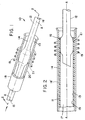
- Figure 1 is a perspective view partially in cross section of an apparatus 10 comprising a part 12 located at least partially within a form 18.
- the part 12 is formed of a polymeric monofilament in the preferred embodiment which extends along an axis A.
- Thermal treatment, i.e. heating, of the monofilament urges it axially toward the area of heating within the form 18 to encourage thickening and results in a larger section as shown.
- Urging the monofilament is, in the preferred embodiment, accomplished by feeding the monofilament axially toward the area of heating from either direction; that is, each end is pushed toward the middle with sufficient force to provide thickening.
- the tube 11 has as inside surface 13 and an outside surface 14 extending between a proximal end 15 and a distal end 16.
- the tube 11 is used as a sheath for a blood gas sensor accommodated in a vascular catheter and has an internal cross sectional shape identical to that of the part 12 and a cross sectional size slightly larger than that of the part 12 prior to being subjected to thermal treatment, as described hereinafter.
- the part 12 may take various forms, but it is preferred that the part 12 have an external cross sectional size substantially identical to the internal cross sectional size of the tube 11 after thermal treatment so that effective sealing is achieved.
- the tube 11 has an internal circular cross sectional shape defined by a bore 17 through the tube 11.
- the part 12 has a circular cross sectional shape of a diameter that may allow axial movement within the tube 11 prior to sealing.
- the part 12 preferably should have a cross sectional shape and size to be substantially near the inside surface 13 upon placement of the part 12 at least partially within the tube 11.
- the part 12, if used to seal the distal end 16, should be slightly tapered to displace any liquid in the tube 11 so that a bubble-free fill remains when the part 12 and tube 11 are sealed.
- An apparatus for assembly of the tube 11 and the expanded part 12 supports the part 12 and/or the tube 11 for relative movement along the axis A placing the part 12 at least partially within the tube 11.
- the precision and speed necessary to place the part 12 within the tube 11 is easily accomplished by automatic machinery that aligns the part 12 and the tube 11 with the axis A so that each is centered and may be placed concentric to one another.
- the part 12 is shown as a preferred monofilament which may be fed into and through a form 18 from either the proximal or distal end 15 or 16 in accord with the desired resuit.
- the part 12 is expanded in the form 18 by application of heat so that it may be located in the tube 11 between the proximal or distal end 15 or 16 thereof or located in the tube 11 near the proximal or distal end 15 or 16 thereof for sealing.
- Figure 2 is a side view in cross section of the form 18' used for assembly of the tube 11 and the part 12 (as reformed in a form 18) and wherein the part 12 is now located at least partially within the distal end 16 of the tube 11.
- the part 12 is inserted into the distal end 16 not through the tube 11 although that is a possible option.
- each of the part 12 and/or the tube 11 is made of a thermoplastic polymer by a process that develops within the polymer a memory of the unshaped thermoplastic polymer prior to forming into the cross sectional shape of the part 12 and/or the tube 11. While the part 12 and the tube 11 may be made from the same polymer they also may be made from different polymers.
- the sealing includes melting and when different polymers are used the sealing is a result of expansion which forms a tight interference fit.
- Residual stresses remaining in the formed part 12 and/or tube 11 may be relaxed by changing temperature causing expansion of the cross sectional size of the tube 11 and/or the part 12.
- the part 12 and/or the tube 11 are preferably made by an extrusion process to develop such processing memory.
- the changing cross sectional size of the tube 11 may provide a thicker wall section after heating and the part 12 may swell when heated.
- the tube 11, as necessary, is urged axially toward the area of heating to prevent thinning which could result in an opening or tear in the tube 11.
- the residual stress in the memory of the process used to make the tube 11, i.e. extrusion could cause the tube 11 to pull apart.
- Urging the tube 11 is accomplished by feeding the tube 11 axially toward the area of heating from one direction and the part 12, such as the monofilament, from the other toward the middle with sufficient force to prevent thinning.
- the fused joint (same polymer) between the part 12 and the tube 11 is therefore uniformly around the part 12 and the seal is sufficient to plug the distal end 16 of the tube 11.
- the forms 18 and 18' are preferably made of a relatively nonconductive material such as tempered glass and the forms 18 and 18' are preferably positioned for relative movement along the axis A for placement about the part 12 as in Figure 1 and may be placed over the tube 11 whereinside the part 12 is located as shown in Figure 2.
- the forms 18 and 18' are shaped and sized to fit the tube 11 inside surface 13 and outside surface 14, respectively and contain it.
- the forms 18 and 18', the tube 11 and the part 12 are preferably substantially circular in cross section. The dimensions are not critical but should be selected to provide the type of fit desired between forms 18 or 18', the part 12 and the tube 11.
- a heater 19 is preferably made of an electrically resistive element wrapped about an outer wall 20 of the form 18 or 18' and is associated therewith for changing the temperature of the tube 11 and the part 12 therewithin sufficiently to relax residual stresses resulting from their respective manufacturing processes.
- the heat applied will thereby cause expansion and engagement of the inside surface 13 and the part 12.
- the heater 19 raises the temperature beyond the glass transition point of the polymer of the tube 11 and/or the part 12 allowing the combined tube 11 and part 12 to expand to the identical cross sectional size of the internal cross section of the form 18 or 18' and to remain expanded after cooling. Melting of the polymer is not required, unless the same polymers are used. Otherwise, sealing is sufficiently accomplished when expansion takes place while the part 12 and the tube 11 are contained by the form 18 or 18'. Thus the contained expansion is adequate to create a joint 21 which will perform acceptably in connection with blood gas sensors. Expansion is for dissimilar polymers and fusion in the form of a melted heat seal occurs between similar polymers.
- the preferred method of assembly of the tube 11 with its axis along its longitude and inside and outside surfaces 13 and 14 extending between proximal and distal ends 15 and 16 over part 12 of a cross sectional shape and size to be near the inside surface 13 of the tube when the part 12 is at least partially within the tube 11 has several steps.
- the method may be performed as shown in the drawings with parts of various configurations.
- Form 18' is shaped and sized to fit about the tube 11 outside surface 14 with heater 19 about outer wall 20 of the form 18'.
- the next step comprises supporting the tube 11 and the part 12 so that relative movement therebetween and along axis A places the part 12 at least partially within the tube 11.
- That step is followed by positioning form 18' for relative movement along axis A for placement about the tube 11 whereinside the part 12 is located to thereby contain the outside surface 14.
- Sufficiently changing the temperature of the tube 11 and the part 12 relaxes residual stresses resulting from the manufacturing process used to make the tube 11 and/or the part 12 for causing engagement of the inside surface 13 of the tube 11 and the part 12.
- the method preferably also includes the added steps of conducting sufficient heat through form 18' into the tube 11 and/or the part 12 to relax residual stresses therein with or without melting the tube 11 and/or the part 12 and clearing fluid (or liquid) about the part 12 before heating.
- the step of clearing fluid is preferably performed by moving a gas along the tube 11 and the step of moving is most preferably performed by applying a vacuum to the junction between tube 11 and part 12.
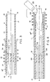
- Figure 3 is a side view in cross section of a plurality of sensors 22 extending through a radially inwardly expanded section 23 located within the tube 11 to illustrate supporting the sensors 22 with the tube 11 as the first step in the assembly of a sensor catheter.
- the radially inwardly expanded section 23 acts to support and separate the sensors of a blood gas catheter sensor.
- the radially inwardly expanded section 23 in Figure 3 shows two sensors passing through respective passageways 24 formed within the tube 11.
- the heater 19 surrounds a form 18'' and heat applied therewith changes the temperature of the tube 11 creating the radially inwardly expanded section 23 within the tube 11 after overcoming the relaxation of residual stresses within the polymer of the tube 11 by pushing the tube axially thus feeding sufficient polymer into the radially inwardly expanding section 23.
- the result is that the radially inwardly expanded section 23 swells when the tube 11 expands and the sensors 22 are captured, supported and held separately in passages 24.
- the preferred embodiment includes temperature sensors made of silver, platinum or gold wire, which are all good conductors of heat. Therefore, to heat properly and prevent the loss of heat to the wires, heating is conducted at just below the melting temperature of the tube 11 polymer, for example, polyethylene, and then quickly for a short time with a pulse of energy through the heating wire coil the temperature is raised to melt the tube 11.
- a seal is thus provided between the tube 11, the radially inwardly expanded section 23 and the sensors 22.
- the tube 11, as necessary, is urged axially toward the area of heating to provide thickening at the radially inwardly expanded section 23. Therefore an opening or tear in the tube 11 is prevented with the added material provided by feeding tube 11 into the space between the sensors 22 and the inside of the unreformed tube 11.
- Urging the tube 11 is preferably accomplished by feeding the tube 11 axially toward the area of heating from either direction; that is, each end 15 and 16 is pushed toward the middle with sufficient force to provide thickening around the sensors 22.
- the joint between the sensors and the tube 11 is therefore uniform around the sensors 22 and the seal is accomplished without added cement.
- a side view in cross section of the supported sensors 22 held within the radially inwardly expanded section 23 of the tube 11 illustrates how the distal end 16 thereof is plugged with the part 12 while a vacuum is drawn to clear liquid resulting when the part 12 is plugged into the tube 11.
- a pipe 25 is located near the distal end 16, i.e. just outside but in position to draw a vacuum near a junction 26 between the part 12 and the tube 11 are heated during the assembly process.
- Arrows B illustrate the vacuum in Figure 4. It should be appreciated that, although not preferred, a sealant may be drawn Into the tube 11 to fill the proximal end 15 and that is shown by the dark areas between the sensors 22 on the left side of Figure 4.
- the part 12 after being sealed in the distal end 16 as in Figures 2 and 4 may be cut to provide a desired shape at the sealed distal end 16.
- the distal seal is accomplished by first pushing the tapered plug into the tube 11 distal end 16 thus displacing liquid therein and drawing excess liquid away with vacuum. Then heating to seal the part 12 and tube 11. Thus, a completely liquid filled space devoid of air bubbles is attained.
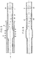
- an optical fiber sensor 27 prepared in accordance with the disclosure in U.S. Patent No. 4,889,407 is shown positioned coaxially within the tube 11 and expanded to engage the inside of the tube 11 by the heater as described hereinbefore.
- the sensor comprises cells 29 arranged in a helical array which substantially covers the cross-sectional area of the fiber and a reflective mirror 30 embedded near the distal end of the optical fiber in accordance with the disclosure in copending patent application No. 887,457.
- the fiber 27 and the tube 11 are shown being sealed together in the side view in cross section of Figure 6.
- An annular space 28 surrounds a distal portion of the fiber 27.
- Figure 6 is a side view in cross section of the sealed fiber 27 and tube 11 shown removed from the glass form used to restrict radial expansion during the heating.
- the tube 11 is urged axially toward the area of heating to prevent thinning which could result in an opening or tear in the tube.
- Urging the tube 11 is preferably accomplished by feeding the tube 11 axially toward the area of heating from either direction; that is, each end is pushed toward the middle with sufficient force to prevent thinning.
- the joint between the fiber 27 and the tube 11 is therefore uniform around the fiber 27 and the seal is sufficient to maintain a liquid in the annular space 28 as needed.
- Figures 7 and 8 show a tip sealing process and apparatus similar to that disclosed in connection with Figures 1, 2 and 4.
- the tube 11 has a monofilament as part 12 and the plug to seal the end is also a part 12.
Abstract
Description
- This invention relates to a tubular assembly, a method for the assembly thereof, and an apparatus for carrying out the method. More particularly, the invention is concerned with a tubular assembly comprising a tube and a part located at least partially within the tube. The part is preferably made of a thermoplastic polymer and relaxation of residual stresses or release of the memory of the manufacturing process used to make the part allows expansion of the part so that it engages the inside surface of the tube.
- Typically tubes are stoppered, plugged or sealed by application of a press fit, shrink fit or wedging component into the bore thereof. Chemicals such as adhesives, sealants or glues are frequently applied to make a fluid tight joint. The accurate application of chemicals to make a small joint fluid tight presents added difficulties of placement and clean up. Often the chemicals used may interfere with the operation of the assembly being made therewith, and also chemical may leach into the blood stream during use of a tubular probe.
- Optical fibers or fiber optic chemical sensors used in vivo as probes must be sensitive to slight changes in gas or ion concentrations. For example, U.S. patent No. 4,200,110 discloses a fiber optic pH probe comprising an ion permeable membrane envelope about the distal ends of a pair of optical fibers. The probe operates on the concept of optically detecting the change in color of a pH sensitive dye.
- U.S. Patent Reissue 31,879 discloses a method for measuring concentration of an analyte in a sample by measuring the intensity of light emitted from a fluorescent indicator attached to an optical fiber.
- U.S. Patent No. 5.047,208 discloses a calorimetric fiber optic sensor for blood gas measurement comprising a pH sensitive dye in a chamber at the distal end of an optical fiber. A white reflective surface is located distal to the chamber.
- The above patents disclose typical miniaturized structures required for in vivo blood analysis.
- U.S. Patent No. 5,005,576 discloses an optical probe for invasive blood gas measurement comprising sensors capable of measuring pH, pO₂ and pCO₂ using absorption dyes. A reflector unit is positioned at the distal end of an outer sheath having a gas-permeable adhesive to close off the end of the probe.
- U.S. Patent No. 5,047,627 discloses a multi-analyte sensor comprising three optical fibers each associated with an indicator matrix and a light reflectance material. Certainty and consistency of assembly is not always repeatable with adhesive attachment, and chemicals in the adhesive may adversely influence the chemistry of the sensor and therefor measurement accuracy.
- U.S. Patent No. 4,889,407 discloses an optical waveguide sensor having a plurality of cells arranged in an array which substantially covers the cross sectional area of the waveguide. Each of the cells contains an indicator sensitive to an analyte in a medium, particularly for the determination of pH and pCO₂ in vivo in blood.
- In accordance with the present invention there is provided a tubular assembly comprising a hollow elongated tube having an internal cross section with an inside surface, a proximal end and a distal end defining a bore around a longitudinal axis, and a part mounted within the bore so that it is at least partially within the tube, the part, preferably made of a thermoplastic polymer, having been thermally treated to expand and engage the inside surface of the tube so that, after change in temperature, the part has an external cross sectional size identical to the internal cross sectional size of the tube and thereby forms a fluid tight seal.
- The tube preferably has an internal cross sectional shape identical to the part and a cross sectional shape identical to the part and a cross sectional size larger than the part prior to changing temperature. The part has an external cross sectional size identical to the internal cross sectional size of the tube after change in temperature. Preferably, the tube has a substantially circular internal cross sectional shape defined by the bore through the tube and the part has a substantially circular external cross sectional shape of a diameter that allows axial movement within the tube before thermal treatment.
- The part should preferably have a cross sectional shape and size to be near the inside surface upon placement of the part at least partially within the tube. The part or the tube may be supported so that relative movement along the axis places the part at least partially within the tube. The part is preferably made of a thermoplastic polymer by a process which develops within the polymer a memory of the unshaped thermoplastic polymer prior to forming into the cross sectional shape of the part so that residual stresses remaining in the formed part are relaxed by changing temperature causing expansion of the cross sectional size of the tube and/or the part. The part and tube are preferably made by an extrusion process to develop memory. The part may be located in the tube between the ends thereof or located in the tube near the proximal or distal end thereof.
- A form, preferably made of a relatively nonconductive material, is preferably positioned for relative movement along the axis for placement about the tube whereinside the part is located. The form is preferably shaped and sized to fit the tube outside surface and contain it. The form, the tube and the part are preferably substantially circular in cross section.
- A heater, preferably made of an electrically resistive element, is wrapped about the form and is associated therewith for changing the temperature of the tube and the part sufficiently to relax residual stresses of their respective manufacturing processes, and thereby cause engagement of the inside surface of the tube and the part. The heater changes the temperature beyond the glass transition point of the polymer allowing the combined tube and part to expand to the identical cross sectional size of the internal cross section of the form and to remain expanded thereafter. As used herein, engagement means that if the part and tube are made of materials that are heat sealable with respect to one another, then they will fuse together when they are thermally heated. Alternatively, if the materials will not fuse then they form a tight fit therebetween upon engagement.
- The invention also provides a method of assembly of a tube with an axis along the longitude thereof and with inside and outside surfaces, a proximal end and a distal end and a part with a cross sectional shape and size similar to the inside surface of the tube when the part is at least partially within the tube using a form shaped and sized to fit about the outside surface of the tube and a heater associated with the form, which comprises the steps of supporting the tube and the part so that relative movement along the tube axis places the part at least partially within the tube; positioning the form for relative movement along the axis for placement about the tube whereinside the part is located to thereby contain the outside surface of the tube; subjecting the tube and the part to thermal treatment to change the temperature sufficiently to relax residual stresses and thereby cause engagement of the inside surface of the tube and the part.
- The method preferably also includes the added steps of clearing fluid about the junction between the part and the tube before heating. Preferably sufficient heat is conducted through the form into the part to form a seal between the part and the inside surface of the tube. The step of clearing fluid is performed most preferably by applying a vacuum near the part during placement.
- The invention also provides an apparatus for assembling a tube and a part inserted at least partially therewithin, characterized by a hollow elongated tube with an axis along the longitude thereof, and with inside and outside surfaces, a proximal end and a distal end; a part with a cross sectional shape and size similar to the inside surface when the part is at least partially within the tube, the part and the tube being supported so that relative movement along the axis places the part at least partially within the tube; a form positioned for relative movement along the axis for placement about the tube whereinside the part is located, the form shaped and sized to fit the tube outside surface and contain it; and a heater associated with the form for providing thermal treatment to change the temperature of the tube and the part sufficiently to relax residual stresses and thereby permit engagement between the inside surface of the tube and the part.
- The invention will be particularly described with reference to preferred embodiments illustrated in the accompanying drawings in which:-
- Figure 1 is a perspective view partially in cross section of an apparatus for expanding a part located at least partially within a form;
- Figure 2 is a side view in cross section of a distal end of a tube with the part located at least partially therewithin for sealing the distal end of the tube; the form is about the tube whereinside the part is located;
- Figure 3 is a side view in cross section of a plurality of sensors extending through a radially expanded section positioned within a tube to illustrate sealing to the tube and the sensors as the first step in the assembly of a sensor catheter;
- Figure 4 is a side view in cross section of the sealed sensors in a radially expanded section of a tube wherein the distal end thereof is sealed with a part while a vacuum is drawn to clear the area around the sensors;
- Figure 5 is a side view in cross section of an optical fiber extending through a tube to illustrate sealing between the tube and the fiber as a step in the assembly of a sensor catheter;
- Figure 6 is a side view in cross section of the sealed fiber, radially expanded within the tube wherein the fiber is engaged tightly against the inside of the tube;
- Figure 7 is a side view in cross section of the sealed fiber in a radially expanded section of a tube, wherein the distal end thereof is sealed with a part while a vacuum draws liquid displaced when the part is pushed into the distal end of the tube; and
- Figure 8 is a side view in cross section of the fiber and part sealed in the tube with the space therebetween filled completely with liquid.
- The embodiment illustrated in Figure 1 comprises an
apparatus 10 for assembly of a tube 11 and apart 12 located at least partially within the tube 11 by relaxation of residual stresses or release of the memory of the manufacturing process used to make thepart 12 by a method which allows engagement of the tube 11 and thepart 12. - The most preferred application of the tubular assembly of the present invention is for the construction of a small (less than 20 gauge) blood gas sensor catheter. Specifically the assembly involves sealing of the distal portion of blood gas sensors within a vascular catheter sheath about sensors such as electrical wires and/or optical fibers passing axially therethrough and termination of the leading end of the blood gas catheter.
- Figure 1 is a perspective view partially in cross section of an
apparatus 10 comprising apart 12 located at least partially within aform 18. Thepart 12 is formed of a polymeric monofilament in the preferred embodiment which extends along an axis A. Thermal treatment, i.e. heating, of the monofilament urges it axially toward the area of heating within theform 18 to encourage thickening and results in a larger section as shown. Urging the monofilament is, in the preferred embodiment, accomplished by feeding the monofilament axially toward the area of heating from either direction; that is, each end is pushed toward the middle with sufficient force to provide thickening. - In Figure 2 of the drawings the tube 11 has as inside
surface 13 and anoutside surface 14 extending between aproximal end 15 and adistal end 16. In a preferred embodiment the tube 11 is used as a sheath for a blood gas sensor accommodated in a vascular catheter and has an internal cross sectional shape identical to that of thepart 12 and a cross sectional size slightly larger than that of thepart 12 prior to being subjected to thermal treatment, as described hereinafter. Thepart 12 may take various forms, but it is preferred that thepart 12 have an external cross sectional size substantially identical to the internal cross sectional size of the tube 11 after thermal treatment so that effective sealing is achieved. - In the preferred embodiment, i.e. a blood gas sensor for a vascular catheter, the tube 11 has an internal circular cross sectional shape defined by a
bore 17 through the tube 11. Similarly, thepart 12 has a circular cross sectional shape of a diameter that may allow axial movement within the tube 11 prior to sealing. Thepart 12 preferably should have a cross sectional shape and size to be substantially near theinside surface 13 upon placement of thepart 12 at least partially within the tube 11. Preferably thepart 12, if used to seal thedistal end 16, should be slightly tapered to displace any liquid in the tube 11 so that a bubble-free fill remains when thepart 12 and tube 11 are sealed. - An apparatus for assembly of the tube 11 and the expanded
part 12 supports thepart 12 and/or the tube 11 for relative movement along the axis A placing thepart 12 at least partially within the tube 11. The precision and speed necessary to place thepart 12 within the tube 11 is easily accomplished by automatic machinery that aligns thepart 12 and the tube 11 with the axis A so that each is centered and may be placed concentric to one another. - In Figure 1 the
part 12 is shown as a preferred monofilament which may be fed into and through aform 18 from either the proximal ordistal end part 12 is expanded in theform 18 by application of heat so that it may be located in the tube 11 between the proximal ordistal end distal end - Figure 2 is a side view in cross section of the form 18' used for assembly of the tube 11 and the part 12 (as reformed in a form 18) and wherein the
part 12 is now located at least partially within thedistal end 16 of the tube 11. Thepart 12 is inserted into thedistal end 16 not through the tube 11 although that is a possible option. Preferably each of thepart 12 and/or the tube 11 is made of a thermoplastic polymer by a process that develops within the polymer a memory of the unshaped thermoplastic polymer prior to forming into the cross sectional shape of thepart 12 and/or the tube 11. While thepart 12 and the tube 11 may be made from the same polymer they also may be made from different polymers. When the same polymer is used the sealing includes melting and when different polymers are used the sealing is a result of expansion which forms a tight interference fit. - Residual stresses remaining in the formed
part 12 and/or tube 11 may be relaxed by changing temperature causing expansion of the cross sectional size of the tube 11 and/or thepart 12. Thepart 12 and/or the tube 11 are preferably made by an extrusion process to develop such processing memory. The changing cross sectional size of the tube 11 may provide a thicker wall section after heating and thepart 12 may swell when heated. During the heating process the tube 11, as necessary, is urged axially toward the area of heating to prevent thinning which could result in an opening or tear in the tube 11. The residual stress in the memory of the process used to make the tube 11, i.e. extrusion, could cause the tube 11 to pull apart. Urging the tube 11 is accomplished by feeding the tube 11 axially toward the area of heating from one direction and thepart 12, such as the monofilament, from the other toward the middle with sufficient force to prevent thinning. The fused joint (same polymer) between thepart 12 and the tube 11 is therefore uniformly around thepart 12 and the seal is sufficient to plug thedistal end 16 of the tube 11. - The
forms 18 and 18' are preferably made of a relatively nonconductive material such as tempered glass and theforms 18 and 18' are preferably positioned for relative movement along the axis A for placement about thepart 12 as in Figure 1 and may be placed over the tube 11 whereinside thepart 12 is located as shown in Figure 2. Theforms 18 and 18' are shaped and sized to fit the tube 11 insidesurface 13 and outsidesurface 14, respectively and contain it. Theforms 18 and 18', the tube 11 and thepart 12 are preferably substantially circular in cross section. The dimensions are not critical but should be selected to provide the type of fit desired betweenforms 18 or 18', thepart 12 and the tube 11. That is, a slip fit during initial assembly so that the tube 11 fits easily into the form 18' and thepart 12, which is preferably tapered, fits into theform 18 and thereafter the tube 11 to displace liquid. The drawings show clearance between thepart 12 and the tube 11 but that is for illustration only since the fit is not loose. - A
heater 19 is preferably made of an electrically resistive element wrapped about anouter wall 20 of theform 18 or 18' and is associated therewith for changing the temperature of the tube 11 and thepart 12 therewithin sufficiently to relax residual stresses resulting from their respective manufacturing processes. The heat applied will thereby cause expansion and engagement of theinside surface 13 and thepart 12. Theheater 19 raises the temperature beyond the glass transition point of the polymer of the tube 11 and/or thepart 12 allowing the combined tube 11 andpart 12 to expand to the identical cross sectional size of the internal cross section of theform 18 or 18' and to remain expanded after cooling. Melting of the polymer is not required, unless the same polymers are used. Otherwise, sealing is sufficiently accomplished when expansion takes place while thepart 12 and the tube 11 are contained by theform 18 or 18'. Thus the contained expansion is adequate to create a joint 21 which will perform acceptably in connection with blood gas sensors. Expansion is for dissimilar polymers and fusion in the form of a melted heat seal occurs between similar polymers. - The preferred method of assembly of the tube 11 with its axis along its longitude and inside and outside surfaces 13 and 14 extending between proximal and
distal ends part 12 of a cross sectional shape and size to be near theinside surface 13 of the tube when thepart 12 is at least partially within the tube 11 has several steps. The method may be performed as shown in the drawings with parts of various configurations. Form 18' is shaped and sized to fit about the tube 11 outsidesurface 14 withheater 19 aboutouter wall 20 of the form 18'. The next step comprises supporting the tube 11 and thepart 12 so that relative movement therebetween and along axis A places thepart 12 at least partially within the tube 11. That step is followed by positioning form 18' for relative movement along axis A for placement about the tube 11 whereinside thepart 12 is located to thereby contain theoutside surface 14. Sufficiently changing the temperature of the tube 11 and thepart 12 relaxes residual stresses resulting from the manufacturing process used to make the tube 11 and/or thepart 12 for causing engagement of theinside surface 13 of the tube 11 and thepart 12. - The method preferably also includes the added steps of conducting sufficient heat through form 18' into the tube 11 and/or the
part 12 to relax residual stresses therein with or without melting the tube 11 and/or thepart 12 and clearing fluid (or liquid) about thepart 12 before heating. The step of clearing fluid is preferably performed by moving a gas along the tube 11 and the step of moving is most preferably performed by applying a vacuum to the junction between tube 11 andpart 12. - Figure 3 is a side view in cross section of a plurality of
sensors 22 extending through a radially inwardly expandedsection 23 located within the tube 11 to illustrate supporting thesensors 22 with the tube 11 as the first step in the assembly of a sensor catheter. The radially inwardly expandedsection 23 acts to support and separate the sensors of a blood gas catheter sensor. The radially inwardly expandedsection 23 in Figure 3 shows two sensors passing throughrespective passageways 24 formed within the tube 11. Theheater 19 surrounds a form 18'' and heat applied therewith changes the temperature of the tube 11 creating the radially inwardly expandedsection 23 within the tube 11 after overcoming the relaxation of residual stresses within the polymer of the tube 11 by pushing the tube axially thus feeding sufficient polymer into the radially inwardly expandingsection 23. The result is that the radially inwardly expandedsection 23 swells when the tube 11 expands and thesensors 22 are captured, supported and held separately inpassages 24. The preferred embodiment includes temperature sensors made of silver, platinum or gold wire, which are all good conductors of heat. Therefore, to heat properly and prevent the loss of heat to the wires, heating is conducted at just below the melting temperature of the tube 11 polymer, for example, polyethylene, and then quickly for a short time with a pulse of energy through the heating wire coil the temperature is raised to melt the tube 11. - A seal is thus provided between the tube 11, the radially inwardly expanded
section 23 and thesensors 22. During the heating process the tube 11, as necessary, is urged axially toward the area of heating to provide thickening at the radially inwardly expandedsection 23. Therefore an opening or tear in the tube 11 is prevented with the added material provided by feeding tube 11 into the space between thesensors 22 and the inside of the unreformed tube 11. Urging the tube 11 is preferably accomplished by feeding the tube 11 axially toward the area of heating from either direction; that is, eachend sensors 22. The joint between the sensors and the tube 11 is therefore uniform around thesensors 22 and the seal is accomplished without added cement. - An assembly, shown in Figures 3 and 4, is easily realized even though the dimensions of the components of the blood gas sensor catheter are small and typically miniaturized. More significantly, the chemistry of the sensor used for optically or electrochemically sensing blood gases may be sensitive to adhesives and so deletion or isolation is of benefit for this reason.
- In Figure 4, a side view in cross section of the supported
sensors 22 held within the radially inwardly expandedsection 23 of the tube 11 illustrates how thedistal end 16 thereof is plugged with thepart 12 while a vacuum is drawn to clear liquid resulting when thepart 12 is plugged into the tube 11. Apipe 25 is located near thedistal end 16, i.e. just outside but in position to draw a vacuum near ajunction 26 between thepart 12 and the tube 11 are heated during the assembly process. Arrows B illustrate the vacuum in Figure 4. It should be appreciated that, although not preferred, a sealant may be drawn Into the tube 11 to fill theproximal end 15 and that is shown by the dark areas between thesensors 22 on the left side of Figure 4. While not specifically shown, thepart 12 after being sealed in thedistal end 16 as in Figures 2 and 4 may be cut to provide a desired shape at the sealeddistal end 16. The distal seal is accomplished by first pushing the tapered plug into the tube 11distal end 16 thus displacing liquid therein and drawing excess liquid away with vacuum. Then heating to seal thepart 12 and tube 11. Thus, a completely liquid filled space devoid of air bubbles is attained. - In Figure 5, an
optical fiber sensor 27 prepared in accordance with the disclosure in U.S. Patent No. 4,889,407 is shown positioned coaxially within the tube 11 and expanded to engage the inside of the tube 11 by the heater as described hereinbefore. The sensor comprisescells 29 arranged in a helical array which substantially covers the cross-sectional area of the fiber and areflective mirror 30 embedded near the distal end of the optical fiber in accordance with the disclosure in copending patent application No. 887,457. Thefiber 27 and the tube 11 are shown being sealed together in the side view in cross section of Figure 6. Anannular space 28 surrounds a distal portion of thefiber 27. - Figure 6 is a side view in cross section of the sealed
fiber 27 and tube 11 shown removed from the glass form used to restrict radial expansion during the heating. During the heating process the tube 11, as necessary, is urged axially toward the area of heating to prevent thinning which could result in an opening or tear in the tube. Urging the tube 11 is preferably accomplished by feeding the tube 11 axially toward the area of heating from either direction; that is, each end is pushed toward the middle with sufficient force to prevent thinning. The joint between thefiber 27 and the tube 11 is therefore uniform around thefiber 27 and the seal is sufficient to maintain a liquid in theannular space 28 as needed. - Figures 7 and 8 show a tip sealing process and apparatus similar to that disclosed in connection with Figures 1, 2 and 4. In these Figures 7 and 8 the tube 11 has a monofilament as
part 12 and the plug to seal the end is also apart 12.
Claims (10)
- A tubular assembly comprising a hollow elongated tube 11 having an internal cross section with an inside surface, a proximal end and a distal end defining a bore around a longitudinal axis, characterized by a part 12 mounted within the bore so that it Is at least partially within the tube 11, the part having been thermally treated to expand and engage the inside surface of the tube so that after change in temperature, the part has an external cross sectional size identical to the internal cross sectional size of the tube, and thereby forms a fluid tight seal.
- A tubular assembly according to claim 1, characterized in that the internal cross section of the tube and the external cross section of the part which engages the inside surface of the tube is substantially circular.
- A tubular assembly according to claim 1 or 2, characterized in that the part is made of a thermoplastic polymer.
- A tubular assembly according to any one of claims 1 to 3, characterized in that the tube 11 accommodates one or more sensors mounted parallel to the longitudinal axis.
- A tubular assembly according to any one of claims 1 to 4, characterized in that the tube 11 is made from an extruded thermoplastic polymer and the thermal treatment thereof results in relaxation of residual stresses and causes the inside surface thereof to move toward the part 12 for engagement.
- A method of assembly of a hollow elongated tube 11 with an axis along the longitude thereof and with inside and outside surfaces, a proximal end and a distal end and a part 12 with a cross sectional shape and size similar to the inside surface of the tube when the part is at least partially within the tube 11 using a form shaped and sized to fit about the outside surface of the tube and a heater associated with the form; characterized by the following steps:
supporting the tube 11 and the part so that relative movement therebetween and along the tube 11 axis places the part at least partially within the tube 11;
positioning the form for relative movement along the axis for placement about the tube 11 whereinside the part is located to thereby contain the outside surface of the tube;
subjecting the tube 11 and the part to thermal treatment to change the temperature sufficiently to relax residual stresses and thereby cause engagement of the inside surface of the tube 11 and the part. - A method according to claim 6,including the step of clearing fluid about the junction between the part and the tube 11 before heating.
- An apparatus 10 for assembling a tube 11 and a part inserted at least partially therewithin, characterized by a hollow elongated tube 11 with an axis along the longitude thereof, and with inside and outside surfaces, a proximal end and a distal end;
a part 12 with a cross sectional shape and size similar to the inside surface when the part is at least partially within the tube 11, the part and the tube 11 being supported so that relative movement along the axis places the part at least partially within the tube 11;
a form positioned for relative movement along the axis for placement about the tube 11 whereinside the part is located, the form shaped and sized to fit the tube 11 outside surface and contain it, and
a heater associated with the form for providing thermal treatment to change the temperature of the tube 11 and the part sufficiently to relax residual stresses and thereby permit engagement between the inside surface of the tube and the part. - An apparatus according to claim 8, characterized in that the tube 11 has a substantially circular internal cross section and a cross sectional size larger than the part 12 prior to thermal treatment and the part has a substantially circular external cross section identical in size to the internal cross section of the tube 11 after thermal treatment.
- An apparatus according to claim 8 or 9, characterized in that the part is made of a thermoplastic polymer by a process that develops within the polymer a memory of the unshaped thermoplastic polymer prior to forming into the cross sectional shape of the part so that residual stresses remaining in the part are relaxed by changing temperature causing expansion of the cross sectional size of the part.
Applications Claiming Priority (2)
| Application Number | Priority Date | Filing Date | Title |
|---|---|---|---|
| US07/887,993 US5280130A (en) | 1992-05-22 | 1992-05-22 | Assembly of a tube and a part and apparatus and method of manufacture |
| US887993 | 2001-06-25 |
Publications (2)
| Publication Number | Publication Date |
|---|---|
| EP0571111A1 true EP0571111A1 (en) | 1993-11-24 |
| EP0571111B1 EP0571111B1 (en) | 1997-08-13 |
Family
ID=25392299
Family Applications (1)
| Application Number | Title | Priority Date | Filing Date |
|---|---|---|---|
| EP93303575A Expired - Lifetime EP0571111B1 (en) | 1992-05-22 | 1993-05-07 | Tubular assembly |
Country Status (7)
| Country | Link |
|---|---|
| US (1) | US5280130A (en) |
| EP (1) | EP0571111B1 (en) |
| JP (1) | JPH0663146A (en) |
| AT (1) | ATE156748T1 (en) |
| AU (1) | AU657857B2 (en) |
| CA (1) | CA2096696A1 (en) |
| DE (2) | DE69313012T2 (en) |
Families Citing this family (13)
| Publication number | Priority date | Publication date | Assignee | Title |
|---|---|---|---|---|
| US5853408A (en) * | 1992-08-20 | 1998-12-29 | Advanced Cardiovascular Systems, Inc. | In-vivo modification of the mechanical properties of surgical devices |
| DE10047850A1 (en) * | 2000-09-27 | 2002-04-25 | Schott Rohrglas Gmbh | Method and device for cutting glass tubes to length |
| JP2010517693A (en) | 2007-02-06 | 2010-05-27 | グルメトリクス, インコーポレイテッド | Optical system and method for ratiometric measurement of blood glucose concentration |
| US7751863B2 (en) * | 2007-02-06 | 2010-07-06 | Glumetrics, Inc. | Optical determination of ph and glucose |
| US8088097B2 (en) * | 2007-11-21 | 2012-01-03 | Glumetrics, Inc. | Use of an equilibrium intravascular sensor to achieve tight glycemic control |
| WO2008141243A2 (en) * | 2007-05-10 | 2008-11-20 | Glumetrics, Inc. | Device and methods for calibrating analyte sensors |
| WO2008141241A1 (en) | 2007-05-10 | 2008-11-20 | Glumetrics, Inc. | Equilibrium non-consuming fluorescence sensor for real time intravascular glucose measurement |
| WO2009129186A2 (en) * | 2008-04-17 | 2009-10-22 | Glumetrics, Inc. | Sensor for percutaneous intravascular deployment without an indwelling cannula |
| JP2013506503A (en) * | 2009-09-30 | 2013-02-28 | グルメトリクス, インコーポレイテッド | Sensor with antithrombogenic coating |
| US8467843B2 (en) | 2009-11-04 | 2013-06-18 | Glumetrics, Inc. | Optical sensor configuration for ratiometric correction of blood glucose measurement |
| US20110152658A1 (en) * | 2009-12-17 | 2011-06-23 | Glumetrics, Inc. | Identification of aberrant measurements of in vivo glucose concentration using temperature |
| JP6313034B2 (en) * | 2013-12-18 | 2018-04-18 | 株式会社カネカ | Catheter manufacturing method and catheter |
| SE2230149A1 (en) * | 2022-05-17 | 2023-11-18 | Cathprint Ab | Tube-in-tube merger |
Citations (6)
| Publication number | Priority date | Publication date | Assignee | Title |
|---|---|---|---|---|
| FR2215123A5 (en) * | 1972-12-22 | 1974-08-19 | Pontigny Jacques | |
| US3861972A (en) * | 1970-08-24 | 1975-01-21 | Johnson & Johnson | Intravenous catheter |
| US4178067A (en) * | 1978-01-19 | 1979-12-11 | Amp Incorporated | Splicing optic waveguides by shrinkable means |
| GB2195069A (en) * | 1986-08-05 | 1988-03-23 | Isopad Ltd | Electric heater for shrinking sleeves about cable splices |
| DE9010609U1 (en) * | 1990-07-14 | 1990-09-20 | Kabelmetal Electro Gmbh, 3000 Hannover, De | |
| EP0439284A1 (en) * | 1990-01-18 | 1991-07-31 | BRITISH TELECOMMUNICATIONS public limited company | Cable closure |
Family Cites Families (9)
| Publication number | Priority date | Publication date | Assignee | Title |
|---|---|---|---|---|
| US31879A (en) * | 1861-04-02 | Machine for finishing leatheb | ||
| SE428596B (en) * | 1975-04-09 | 1983-07-11 | Raychem Corp | DEVICE FOR CONNECTING SUBSTRATE EXV RODS INCLUDING A MEMORIAL METAL BODY |
| US4200110A (en) * | 1977-11-28 | 1980-04-29 | United States Of America | Fiber optic pH probe |
| US4754538A (en) * | 1983-11-15 | 1988-07-05 | Raychem Corporation | Annular tube-like driver |
| JPS63318954A (en) * | 1987-06-23 | 1988-12-27 | Terumo Corp | Intravascular indwelling catheter |
| DE3877949T2 (en) * | 1988-04-09 | 1993-05-19 | Hewlett Packard Gmbh | MANUFACTURING METHOD FOR AN OPTICAL PROBE. |
| US4889407A (en) * | 1988-12-02 | 1989-12-26 | Biomedical Sensors Limited | Optical waveguide sensor and method of making same |
| US5047208A (en) * | 1989-02-23 | 1991-09-10 | Medtronic, Inc. | Blood gas monitoring sensors |
| US5047627A (en) * | 1990-05-18 | 1991-09-10 | Abbott Laboratories | Configuration fiber-optic blood gas sensor bundle and method of making |
-
1992
- 1992-05-22 US US07/887,993 patent/US5280130A/en not_active Expired - Fee Related
-
1993
- 1993-05-07 DE DE69313012T patent/DE69313012T2/en not_active Expired - Fee Related
- 1993-05-07 AT AT93303575T patent/ATE156748T1/en not_active IP Right Cessation
- 1993-05-07 EP EP93303575A patent/EP0571111B1/en not_active Expired - Lifetime
- 1993-05-18 DE DE9307575U patent/DE9307575U1/en not_active Expired - Lifetime
- 1993-05-20 CA CA002096696A patent/CA2096696A1/en not_active Abandoned
- 1993-05-21 AU AU38734/93A patent/AU657857B2/en not_active Ceased
- 1993-05-24 JP JP5121452A patent/JPH0663146A/en active Pending
Patent Citations (6)
| Publication number | Priority date | Publication date | Assignee | Title |
|---|---|---|---|---|
| US3861972A (en) * | 1970-08-24 | 1975-01-21 | Johnson & Johnson | Intravenous catheter |
| FR2215123A5 (en) * | 1972-12-22 | 1974-08-19 | Pontigny Jacques | |
| US4178067A (en) * | 1978-01-19 | 1979-12-11 | Amp Incorporated | Splicing optic waveguides by shrinkable means |
| GB2195069A (en) * | 1986-08-05 | 1988-03-23 | Isopad Ltd | Electric heater for shrinking sleeves about cable splices |
| EP0439284A1 (en) * | 1990-01-18 | 1991-07-31 | BRITISH TELECOMMUNICATIONS public limited company | Cable closure |
| DE9010609U1 (en) * | 1990-07-14 | 1990-09-20 | Kabelmetal Electro Gmbh, 3000 Hannover, De |
Also Published As
| Publication number | Publication date |
|---|---|
| AU3873493A (en) | 1993-12-23 |
| DE9307575U1 (en) | 1993-09-23 |
| AU657857B2 (en) | 1995-03-23 |
| CA2096696A1 (en) | 1993-11-23 |
| ATE156748T1 (en) | 1997-08-15 |
| JPH0663146A (en) | 1994-03-08 |
| DE69313012T2 (en) | 1997-12-04 |
| EP0571111B1 (en) | 1997-08-13 |
| DE69313012D1 (en) | 1997-09-18 |
| US5280130A (en) | 1994-01-18 |
Similar Documents
| Publication | Publication Date | Title |
|---|---|---|
| EP0571111B1 (en) | Tubular assembly | |
| US5335305A (en) | Optical sensor for fluid parameters | |
| US5397411A (en) | Method for making optical probe | |
| US4682895A (en) | Fiber optic probe for quantification of colorimetric reactions | |
| US5166990A (en) | Multiple optical fiber event sensor and method of manufacture | |
| EP0339780B1 (en) | Capillary detector cartridge for electrophoresis | |
| US5366903A (en) | Method of photometric in vitro determination of the content of an analyte in a sample of whole blood | |
| Pantano et al. | Analytical applications of optical imaging fibers | |
| EP0471519A1 (en) | Multiple optical fiber event sensor and method of manufacture | |
| DK168250B1 (en) | Multichannel electromagnetic radiation transmission system | |
| EP0234928A2 (en) | Optical fiber apparatus | |
| EP0829027A1 (en) | Robust spectroscopic optical probe | |
| JP2628355B2 (en) | Fiber optic probe connector for physiological measurement devices | |
| EP0183329A2 (en) | Pressure-sensitive optrode | |
| JPH0363024B2 (en) | ||
| EP0578980B1 (en) | Environmentally robust fiber optic coupler and method | |
| EP0253492B1 (en) | Fibre-optic probe | |
| CA2489858C (en) | Splice for optical cable | |
| US5271073A (en) | Optical fiber sensor and method of manufacture | |
| US5257338A (en) | Device for transmitting and returning light and apparatus and method of manufacture | |
| US20100284863A1 (en) | Biosensor cartridge and biosensor mounting system with integral fluid storage and fluid selection mechanisms | |
| EP0160683A1 (en) | A method and apparatus for making a fluid electrode | |
| DK1213572T3 (en) | Process for producing a sealed temperature probe and probe thus prepared | |
| JPH02183145A (en) | Optical fiber sensor | |
| US20220221409A1 (en) | A sensor |
Legal Events
| Date | Code | Title | Description |
|---|---|---|---|
| PUAI | Public reference made under article 153(3) epc to a published international application that has entered the european phase |
Free format text: ORIGINAL CODE: 0009012 |
|
| 17P | Request for examination filed |
Effective date: 19930515 |
|
| AK | Designated contracting states |
Kind code of ref document: A1 Designated state(s): AT BE CH DE DK ES FR GB GR IE IT LI LU NL PT SE |
|
| 17Q | First examination report despatched |
Effective date: 19950825 |
|
| GRAG | Despatch of communication of intention to grant |
Free format text: ORIGINAL CODE: EPIDOS AGRA |
|
| GRAH | Despatch of communication of intention to grant a patent |
Free format text: ORIGINAL CODE: EPIDOS IGRA |
|
| GRAH | Despatch of communication of intention to grant a patent |
Free format text: ORIGINAL CODE: EPIDOS IGRA |
|
| GRAA | (expected) grant |
Free format text: ORIGINAL CODE: 0009210 |
|
| RAP1 | Party data changed (applicant data changed or rights of an application transferred) |
Owner name: DIAMETRICS MEDICAL LTD. |
|
| AK | Designated contracting states |
Kind code of ref document: B1 Designated state(s): AT BE CH DE DK ES FR GB GR IE IT LI LU NL PT SE |
|
| PG25 | Lapsed in a contracting state [announced via postgrant information from national office to epo] |
Ref country code: GR Free format text: LAPSE BECAUSE OF FAILURE TO SUBMIT A TRANSLATION OF THE DESCRIPTION OR TO PAY THE FEE WITHIN THE PRESCRIBED TIME-LIMIT Effective date: 19970813 Ref country code: ES Free format text: THE PATENT HAS BEEN ANNULLED BY A DECISION OF A NATIONAL AUTHORITY Effective date: 19970813 Ref country code: DK Free format text: LAPSE BECAUSE OF NON-PAYMENT OF DUE FEES Effective date: 19970813 |
|
| REF | Corresponds to: |
Ref document number: 156748 Country of ref document: AT Date of ref document: 19970815 Kind code of ref document: T |
|
| REG | Reference to a national code |
Ref country code: CH Ref legal event code: EP |
|
| REF | Corresponds to: |
Ref document number: 69313012 Country of ref document: DE Date of ref document: 19970918 |
|
| REG | Reference to a national code |
Ref country code: CH Ref legal event code: NV Representative=s name: PATENTANWALTSBUREAU R. A. MASPOLI |
|
| ITF | It: translation for a ep patent filed |
Owner name: ING. C. GREGORJ S.P.A. |
|
| PG25 | Lapsed in a contracting state [announced via postgrant information from national office to epo] |
Ref country code: SE Effective date: 19971113 |
|
| PG25 | Lapsed in a contracting state [announced via postgrant information from national office to epo] |
Ref country code: PT Effective date: 19971114 |
|
| ET | Fr: translation filed | ||
| PGFP | Annual fee paid to national office [announced via postgrant information from national office to epo] |
Ref country code: AT Payment date: 19980312 Year of fee payment: 6 |
|
| PGFP | Annual fee paid to national office [announced via postgrant information from national office to epo] |
Ref country code: GB Payment date: 19980320 Year of fee payment: 6 |
|
| PGFP | Annual fee paid to national office [announced via postgrant information from national office to epo] |
Ref country code: BE Payment date: 19980402 Year of fee payment: 6 |
|
| PGFP | Annual fee paid to national office [announced via postgrant information from national office to epo] |
Ref country code: FR Payment date: 19980407 Year of fee payment: 6 |
|
| PG25 | Lapsed in a contracting state [announced via postgrant information from national office to epo] |
Ref country code: LU Free format text: LAPSE BECAUSE OF NON-PAYMENT OF DUE FEES Effective date: 19980507 Ref country code: IE Free format text: LAPSE BECAUSE OF NON-PAYMENT OF DUE FEES Effective date: 19980507 |
|
| PG25 | Lapsed in a contracting state [announced via postgrant information from national office to epo] |
Ref country code: LI Free format text: LAPSE BECAUSE OF NON-PAYMENT OF DUE FEES Effective date: 19980531 Ref country code: CH Free format text: LAPSE BECAUSE OF NON-PAYMENT OF DUE FEES Effective date: 19980531 |
|
| PLBE | No opposition filed within time limit |
Free format text: ORIGINAL CODE: 0009261 |
|
| STAA | Information on the status of an ep patent application or granted ep patent |
Free format text: STATUS: NO OPPOSITION FILED WITHIN TIME LIMIT |
|
| 26N | No opposition filed | ||
| PG25 | Lapsed in a contracting state [announced via postgrant information from national office to epo] |
Ref country code: NL Free format text: LAPSE BECAUSE OF NON-PAYMENT OF DUE FEES Effective date: 19981201 |
|
| REG | Reference to a national code |
Ref country code: CH Ref legal event code: PL |
|
| NLV4 | Nl: lapsed or anulled due to non-payment of the annual fee |
Effective date: 19981201 |
|
| PG25 | Lapsed in a contracting state [announced via postgrant information from national office to epo] |
Ref country code: DE Free format text: LAPSE BECAUSE OF NON-PAYMENT OF DUE FEES Effective date: 19990302 |
|
| PG25 | Lapsed in a contracting state [announced via postgrant information from national office to epo] |
Ref country code: GB Free format text: LAPSE BECAUSE OF NON-PAYMENT OF DUE FEES Effective date: 19990507 Ref country code: AT Free format text: LAPSE BECAUSE OF NON-PAYMENT OF DUE FEES Effective date: 19990507 |
|
| PG25 | Lapsed in a contracting state [announced via postgrant information from national office to epo] |
Ref country code: BE Free format text: LAPSE BECAUSE OF NON-PAYMENT OF DUE FEES Effective date: 19990531 |
|
| BERE | Be: lapsed |
Owner name: DIAMETRICS MEDICAL LTD Effective date: 19990531 |
|
| GBPC | Gb: european patent ceased through non-payment of renewal fee |
Effective date: 19990507 |
|
| PG25 | Lapsed in a contracting state [announced via postgrant information from national office to epo] |
Ref country code: FR Free format text: LAPSE BECAUSE OF NON-PAYMENT OF DUE FEES Effective date: 20000131 |
|
| REG | Reference to a national code |
Ref country code: FR Ref legal event code: ST |
|
| PG25 | Lapsed in a contracting state [announced via postgrant information from national office to epo] |
Ref country code: IT Free format text: LAPSE BECAUSE OF NON-PAYMENT OF DUE FEES;WARNING: LAPSES OF ITALIAN PATENTS WITH EFFECTIVE DATE BEFORE 2007 MAY HAVE OCCURRED AT ANY TIME BEFORE 2007. THE CORRECT EFFECTIVE DATE MAY BE DIFFERENT FROM THE ONE RECORDED. Effective date: 20050507 |