EP0571985A2 - Positive fixation device - Google Patents
Positive fixation device Download PDFInfo
- Publication number
- EP0571985A2 EP0571985A2 EP93108518A EP93108518A EP0571985A2 EP 0571985 A2 EP0571985 A2 EP 0571985A2 EP 93108518 A EP93108518 A EP 93108518A EP 93108518 A EP93108518 A EP 93108518A EP 0571985 A2 EP0571985 A2 EP 0571985A2
- Authority
- EP
- European Patent Office
- Prior art keywords
- end portion
- distal end
- hook
- electrode
- hollow
- Prior art date
- Legal status (The legal status is an assumption and is not a legal conclusion. Google has not performed a legal analysis and makes no representation as to the accuracy of the status listed.)
- Granted
Links
Images


Classifications
-
- A—HUMAN NECESSITIES
- A61—MEDICAL OR VETERINARY SCIENCE; HYGIENE
- A61N—ELECTROTHERAPY; MAGNETOTHERAPY; RADIATION THERAPY; ULTRASOUND THERAPY
- A61N1/00—Electrotherapy; Circuits therefor
- A61N1/02—Details
- A61N1/04—Electrodes
- A61N1/05—Electrodes for implantation or insertion into the body, e.g. heart electrode
- A61N1/056—Transvascular endocardial electrode systems
- A61N1/057—Anchoring means; Means for fixing the head inside the heart
- A61N1/0573—Anchoring means; Means for fixing the head inside the heart chacterised by means penetrating the heart tissue, e.g. helix needle or hook
Definitions
- This invention relates to implantable defibrillation and pacing leads and more particularly to devices of this type which employ fixation structure operative to engage and draw tissue laterally toward the distal end of the defibrillation or pacing lead.
- the instant fixation devices are appropriate for minimally invasive defibrillation and use with new, deployable defibrillation leads which are implanted without the currently practiced thoracotomy procedures.
- the implantation of these leads requires making a small incision in the chest to gain access to the pericardial space.
- the defibrillation leads are then threaded through the incision and into the pericardial space either alone or through the lumen of a thin walled guiding catheter.
- a deployment action is performed to expand the surface area of the lead. At this point, the lead is generally held against the myocardial surface by the pericardium.
- fixation is required. Fixation to the pericardial sack is the safest approach since it completely avoids accidental laceration of the myocardial circulation.
- the instant fixation device utilizes hooks that penetrate through the pericardium and return to the lead. These designs do not leave a sharp, pointed object imbedded in the tissue. Still further, the fixation means needs to be robust in order to remain effective through the violent contractions experienced by the heart during initial defibrillation testing.
- An internally deployable defibrillator electrode is disclosed in- U.S. Patent No. 4,860,760, but does not include structure for fixation prior to or subsequent to deployment of the electrode.
- U.S. Patent No. 4,567,900 also discloses an internally deployable defibrillator electrode, but here again also is absent fixation structure.
- U.S. Patent No. 4,624,265 employs both rotary hook and rotary screw fixation devices for an electro-catheter, but rotary hook and rotary screw fixation devices which must be actuated by rotary torque applied at the proximal end of the electro-catheter are objectionable and, this patent does not disclose rotary hook or screw fixation devices which may be utilized in conjunction with an internally deployable defibrillator electrode.
- U.S. Patent No. 3,814,104 describes a pacemaker lead which attaches to endocardial tissue by means of two gently curved hooks advanced from the lead by means of axial force applied by an internal stylet.
- the essentially straight hooks provide some degree of fixation but can allow the lead to be simply pulled from the tissue.
- a special separate flexible catheter is required to force the hooks together if the device needs to be repositioned.
- U.S. Patent No. 4,058,128 describes a pacemaker lead which attaches to the myocardium by means of a single, completely exposed barbed hook.
- a significant chest incision is performed to expose the pericardial surface
- the lead is grasped with a special grasping tool, both the lead and grasping tool are introduced through the relatively large incision (compared to the lead body itself), the barbed hook is inserted into the myocardial tissue and the grasping tool is removed.
- reintroduction of the grasper is necessary to reverse and then repeat the process.
- U.S. Patent No. 4,013,690 describes a complex self-suturing, endocardial pacemaker lead and a special integral handle-stylet device permanently accompanying the lead from the time of manufacture.
- the handle activates the ejection of a thin, malleable wire through a distal tubular die and into the tissue. If the acute performance of the lead is satisfactory, the wire suture is broken at a predetermined separation point by means of rotation of the handle and the handle-stylet is removed. Any attempt the reposition this lead after this point would not be possible.
- U.S. Patent No. 4,142,530 describes an epicardial pacemaker lead which is once again implanted through a significant incision in the patient's chest. Once positioned against the epicardium, the lead body is simultaneously pulled along and pressed onto the surface of the heart in order to engage the tissue in at least two curved pointed electrodes. This implantation requires the combination of lead retraction and compression by the surgeon. The means by which the compressive force is applied to the lead head is unclear. A straight, forward anchor is then activated by advancing a stylet against an internal feature of the anchor. This forward anchor generates a force which directs the curved electrodes against the tissue. A nylon wire is attached to the anchor to provide a means for the surgeon to retract the anchor.
- U.S. Patent No. 4,233,992 discloses an endocardial electrode with a deployable helical hook. A provision is made to include a barb on these hooks. These leads are implanted using routine surgical technique.
- the first embodiment employs a non-reversible triggering element to deploy the hook.
- the second embodiment is deployed by means of a conically tipped stylet. Engagement of the heart tissue is accomplished by the application of external torque on the lead body by the surgeon.
- U.S. Patent No. 4,357,946 teaches about an epicardial pacemaker lead which is to be implanted during thoracic surgery. Deployment of the helical screw fixation device is accomplished by means of rotation imparted by a stylet while the electrode head is in some fashion held upon the epicardial surface through an external force.
- U.S. Patent No. 4,378,023 discloses a percutaneously implanted myocardial electrode which blindly penetrates the myocardium to a significant depth. Fixation hooks are released within the myocardial tissue itself. External rotation is necessary to further deploy the fixation hooks. External traction is necessary to set the hooks into the tissue in at least one design.
- U.S. Patent No. 4,649,938 discloses an endocardial stimulating electrode which is implanted by means of routine surgical technique and requires the use of external rotation of the lead body to advance and attach helical screw to the tissue. Once fixed to the tissue, the spring-loaded helical screw holds the tissue in close proximity to the electrode.
- U.S. Patent No. 4,858,623 discloses an endocardial pacemaker lead which deploys a simple spring loaded hook from the lead by means of an axial force applied to an internal stylet. Once deployed, the lead engages tissue following application of external rotation imparted to the lead body. If repositioning is necessary, the stylet is further advanced to locate the hook in its most distal position. The lead is then pulled free of the tissue by simple traction.
- the defibrillator electrode or electro-catheter of the instant invention is specifically designed for use as an internal defibrillator electrode, but also may be used as a pacing lead.
- the instant invention incorporates fixation structure which is effective to hook engage adjacent tissue and to draw the adjacent tissue laterally into engagement with that portion of the electro-catheter from which the hook is supported, whether the fixation structure is carried by the distal end of the electro-catheter or an intermediate length portion of the electro-catheter.
- the main object of this invention is to provide an electro-catheter which may be positioned using routine implant techniques including the use of an internal stylet or an outer tubular catheter, each of which being withdrawable to effect deployment of a resilient deformable distal end electrode of predetermined shape.
- Another object of this invention is to provide an implantable and internally deployable defibrillation electrode including fixation structure which may be used to effect fixation of the electrode prior to internal deployment of the electrode.
- Still another object of this invention is to provide an implantable and internally deployable defibrillation electrode including fixation structure which will allow for fixation of the deployable distal end of the electrode subsequent to deployment thereof.
- Yet another important object of this invention is to provide an implantable defibrillation electrode fixation structure which may be actuated and deactuated merely through the utilization of a fixation stylet.
- a further important object of this invention is to provide an implantable defibrillation electrode including fixation structure operative to engage adjacent tissue and to draw the distal end of the defibrillation electrode laterally into engagement with the engaged tissue.
- Another important object of this invention is to provide an implantable defibrillation electrode including fixation structure which may be actuated by longitudinal force as opposed to rotary torque.
- Still another object of this invention is to provide an implantable defibrillation electrode in accordance with the preceding object and incorporating a spring loading mechanism wherein the spring biasing action thereof accomplishes the fixation action and is more readily operable to release and subsequently reestablish fixation in the event it is desired to shift the positioning of a deployed defibrillation electrode subsequent to initial fixation thereof.
- a final object of this invention to be specifically enumerated herein is to provide an implantable defibrillation electrode in accordance with the preceding objects and which will conform to conventional forms of manufacture, be of simple construction and easy to use so as to provide a device that will be economically feasible, long-lasting and relatively trouble free in operation.
- an internally deployable electro-catheter referred to in general by the reference numeral 10 employing a deployable distal end portion 12 and a proximal end portion 14.
- the distal end portion 12, in Figure 2 is illustrated in its deployed pre-configured flat zig-zag shape, the entire length of the electro-catheter being flexible and the distal end portion 12 being capable of being straightened either through the use of an internal straightening stylet inserted thereinto from the proximal end portion 14 or an external flexible tubular catheter (not shown) of greater stiffness than the distal end portion 12.
- the precise electrical construction of the deployable end portion 12 may be of any suitable well known type. Suffice it to say that through leads extending the length of the electro-catheter, electrical energy is delivered from a pulse generator to the cardiac tissue of the patient via the conductive distal end portion 12 of the structure.
- the terminal distal end 16 comprises a dielectric (biocompatible polymer) tubular housing 19 and defines an endwise outwardly opening cylindrical cavity 18 into which the distal end 20 of a helical tubular spring 22 extending through the distal end portion 12 projects, the proximal end (not shown) of the spring 22 being anchored relative to the proximal end portion 14 in any convenient manner.
- the distal end 20 includes a stretchable diametrically enlarged portion 24 disposed within the cavity 18 terminating in a diametrically reduced terminal end 26 also disposed within the cavity 18.
- the portion 24 comprises axial thrust developing means for yieldingly biasing the terminal end 26 in one direction.
- the base end 28 of a reverse turned spring hook 30 is anchored to the terminal end 26 of the spring 22 and includes a reversed turned hook 30 on its free end 32 substantially fully contained within the cavity 18.
- a fixation stylet (see Figure 4B) is associated with the proximal end portion 14 and inserted through the electro-catheter 10 for engagement with the interior of the terminal end 26 of the spring 22 in which the base end 28 of the spring hook 30 is anchored.
- the fixation stylet thereafter is actuated against the terminal end 26 in a fashion similar to a camera cable release to force the latter toward the open end of the cavity 18 to and past the phantom line position thereof illustrated in Figure 1 thus expanding the large diameter end portion 24 of the spring 22.
- Displacement of the terminal end 26 past the phantom line position of Figure 1 projects the bend 23 of the reversed turned hook 32 from the open end of the cavity 18 for lateral displacement therefrom and engagement of the free end 32 thereof with the tissue to which the terminal distal end 16 is to be fixed. Then, the fixation stylet is released to enable retraction of the hook 30 from the phantom line position thereof to the solid line position thereof to thereby draw the exterior of the terminal distal end 16 laterally into tight contact with the tissue engaged by the hook 30.
- fixation stylet may be removed and the tubular catheter may be withdrawn from about the deployable end portion 12 to thereby enable the latter to deploy and assume the pre-configured shape thereof illustrated in Figure 2.
- a modified form of electro-catheter is referred to in general by the reference 10' incorporating a deployable distal end portion 12' and a proximal end portion 14'.
- the electro-catheter 10' is of a design to be inserted through the utilization of a tubular catheter and the deployable distal end portion 12' thereof is in the form of a flat spiral coil.
- the electro-catheter 10' incorporates a tubular housing 19' corresponding to the tubular housing 19 defining the cavity 18.
- the housing 19' is serially disposed within the electro-catheter 10' between the proximal end portion 14' thereof and the deployable distal end portion 12' thereof.
- the internal structure of the housing 19' is substantially identical to the internal structure of the housing 19 in that a helical tubular spring 22' corresponding to the spring 22 has its distal end 20' projecting into the cavity 18' of the housing 19' and the base end 28' of a spring hook 30' corresponding to the spring hook 30 is anchored in the terminal end 26' of the distal end 20', the distal end 20' including an enlarged diameter end portion 24' corresponding to the end portion 24.
- the distal end portion 12' is, however, provided with a slot 29 through which the free end 32' of the spring hook 30' may be extended upon utilization of a fixation stylet, for example, of the camera shutter cable release type herein above referred to. Accordingly, the housing 19' of the electro-catheter 10' may be laterally anchored to suitable internal tissues through the utilization of a fixation stylet. In this manner, an intermediate portion of the electro-catheter 10' can be affixed to body tissue after the distal active end of the electrode is permitted to deploy into the pre-configured shape illustrated in Figure 3.
- FIG. 4A and 4B there may be seen a terminal distal end 16'' of an electro-catheter 10'' which may be considered as substantially identical to the electro-catheter 10, except for the terminal distal end 16'' thereof.
- the electro-catheter 10'' includes an internal coil spring 22'' corresponding to the spring 20 equipped with a distal end 20'' incorporating an enlarged diameter end portion 24'' and a terminal end 26'', all of which are enclosed with a housing 19'', the distal terminal end of the housing 19'' being hollow and frusto conical as at 21 and provided with a partial spiral slot 23.
- the terminal distal end of housing 19'' is open as at 25 on its minor diameter end and the terminal end 26'' is projectable through the open end 25 and includes an end enlargement 27 which is retractable only partly into the open end 25.
- the terminal end 26'' has the base end of a curved hook 33 anchored thereto and the hook 33 projects outwardly through and is slidably received within the slot 23, the slot 23 extending less than 180 degrees about the terminal distal end 21.
- the housing 19'' may comprise the terminal distal end of an electro-catheter such as the electro-catheter 10 in lieu of the terminal distal end 19 thereof.
- the electro-catheter 10'' would be designed for insertion in the same manner as the electro-catheter 10 and fixed in the desired position prior to deployment of the deployable distal end portion 12'' of the electro-catheter 10'' corresponding to the deployable distal end portion 12.
- a fixation stylet 17 is inserted into the electro-catheter 10'' and associated with the proximal end portion thereof.
- fixation stylet is operated in a fashion similar to a camera cable release to lengthwise elongate the enlarged diameter end portion 24'' from the condition thereof illustrated in Figure 4 to the expanded condition thereof illustrated in Figure 4B, which movement causes the hook 33 to move from the end 37 of the slot 23 in which the hook 33 is retracted to the end 39 of the slot 23, in which position the hook 33 is fully extended, the terminal end 26'' being projected through the open end 25 of the terminal distal end 21.
- fixation stylet may be released so that the spring biasing action of the enlarged diameter end portion 24'' may retract the hook 33 back through the slot 23 from the end 39 thereof to the end 37 thereof, during which movement the hook 33 engages adjacent tissue and laterally draws the terminal distal end 21 toward and against that tissue and simultaneously draws the sharp point 33' into the outwardly opening recess 45 shown in Figure 4.
- the tubular delivery catheter (not shown) may be withdrawn to thereby allow the distal end portion 12'' to deploy and assume the pre-configured shape of the-distal end portion 12 illustrated in Figure 2.
- the housings 19, 19' and 19'' are insulated from the electrical conductors (not shown) which bring electrical energy to conductive outer surface portions of the distal end portions 12, 12' and 12''.
- the phantom lines 41 and 41' indicate the structure of the distal end portions 12 and 12', respectively, which comprise the spiral conductors disposed thereabout and which bring electrical energy to the outer surface portions of the end portions 12 and 12' (the electricity being supplied thereto through proximal lumen tubing or possible bilumen tubing with one lumen incorporating the electrical conductor leading to the conductors and the second lumen dedicated to operation of the fixation device).
- the hook 33 When the hook 33 is disposed in the end 37 of the slot 23 (subsequent to release of engagement of the hook 33 with organ tissue), it is positioned immediately forward of the shield 45 to thereby facilitate repositioning or removal of the electro-catheter 10'' subsequent to its usage.
- Distal end portion 112 includes a dielectric tubular housing 119 in which the distal end 120 of a helical tubular spring 122 is disposed.
- the distal end 120 includes a strengthable diametrically enlarged portion 124 -disposed within a hollow cavity 118 formed in the housing 119 and the diametrically enlarged portion 124 terminates in a diametrically reduced terminal end 126 to which there is secured one end 127 of a thrust rod 129 through the utilization of a suitable fastener 121.
- the other end of the rod 129 has one end one 131 of a curved hook 133 pivotally secured thereto as at 135 and the free end of the hook 133 is pointed as at 137.
- the free end portion of the hook 131 projects through a radial opening 139 formed in the housing 119 and extending longitudinally thereof, the housing 119 including cam surfaces 141 and 143 at the proximal and distal ends, respectively, of the opening or slot 139.
- the diametrically reduced terminal end 126 and the rod 129 may be advanced toward the rounded distal end 145 of the housing 19 in the same manner in which the terminal end 26 may be advanced from the solid line position thereof in Figure 1 to the phantom line position thereof illustrated in Figure 1.
- the hook 133 When the rod 129 is in the retracted solid line position thereof illustrated in Figure 5, the hook 133 is fully retracted and has its pointed end 137 received within an outwardly opening notch 147 formed in one side of the distal end 145 of the housing 119. However, when the diametrically reduced portion 126 and the rod 129 are advanced toward the distal end 145, the cam surface 143 swings the hook 133 in a counterclockwise direction as viewed in Figure 5 toward the lowermost extended position thereof illustrated in phantom lines.
- the housing 119 is positioned adjacent the pericardial sack and the diametrically reduced end portion 126 and the rod 129 are then allowed to retract toward the proximal end of the housing 119 where upon the hook 133 will hook engage the pericardial sack and swing toward the solid line position of the hook illustrated in Figure 5 thereby fixing the housing 119 to the pericardial sack.
- FIG. 6 illustrates the single hook 133 of the electro-catheter 110 illustrated in Figure 5 and Figure 7 illustrates a further modified form of electro-catheter 210 which is substantially identical to the electro-catheter 10, except that the electro-catheter 210 includes a pair of hooks or hook members 233 and a pair of recesses 247 in which to receive the free pointed ends of the hook members 233.
- the housing 219 of the electro-catheter 210 includes a pair radial openings or slots 239 through which the hooks or hook members 233 operate.
- fixation devices illustrated in Figures 5-7 may be incorporated either at the distal end of a deployable defibrillator end portion such as the end portion 12, or at the proximal end of a deployable end portion such as the end portion 12' illustrated in Figure 3.
- FIG. 3 there may be seen yet a another form of deployable electro-catheter referred to in general by the reference numeral 310 including a deployable distal end portion 312.
- the deployable end portion 312 supports a tubular housing 319 therefrom including a radial slot or opening 339 terminating at cam surfaces 341 and 343 corresponding to the surfaces 141 and 143 and a rod 329 is reciprocal within the housing 319 corresponding to the rod 129 and has a hook or hook member 333 pivotally mounted from the distal end thereof as at 335.
- the rod 329 is yieldingly biased toward the distal end 345 of the housing 319 by a compression spring 349 and retracted away from the distal end 345 by a pull cord or the like 351.
- the hook 333 is cammed by the cam surface 341 to the phantom line position thereof illustrated in Figure 8, and when the spring 349 is allowed to shift the rod 329 toward the distal end portion 345, the hook 333 is pivoted from the phantom line position thereof illustrated in Figure 8 to the solid line position thereof.
- all of the fixation devices 110, 210 and 310 may be used on either the distal end portion 12 of the distal end portion 12'.
Abstract
Description
- This invention relates to implantable defibrillation and pacing leads and more particularly to devices of this type which employ fixation structure operative to engage and draw tissue laterally toward the distal end of the defibrillation or pacing lead.
- The instant fixation devices are appropriate for minimally invasive defibrillation and use with new, deployable defibrillation leads which are implanted without the currently practiced thoracotomy procedures. The implantation of these leads requires making a small incision in the chest to gain access to the pericardial space. The defibrillation leads are then threaded through the incision and into the pericardial space either alone or through the lumen of a thin walled guiding catheter. Once initially placed in his fashion, a deployment action is performed to expand the surface area of the lead. At this point, the lead is generally held against the myocardial surface by the pericardium.
- Because of the lubricious conditions which exist within that space, and the need to more precisely position the leads for defibrillation, lead fixation is required. Fixation to the pericardial sack is the safest approach since it completely avoids accidental laceration of the myocardial circulation. For additional safety, the instant fixation device utilizes hooks that penetrate through the pericardium and return to the lead. These designs do not leave a sharp, pointed object imbedded in the tissue. Still further, the fixation means needs to be robust in order to remain effective through the violent contractions experienced by the heart during initial defibrillation testing. Also, the ability to control device fixation using only simple axial, back-and-forth, "camera cable release-like" motions on common, off-the-shelf devices such as guidewires and stylets is highly desired. This is due, in part, to the fact that the lead may be partially or completely deployed and that lead body rotation and traction due to the remoteness of the insertion site may not be useful technique at this stage of the implant. It also should be noted that although the instant focus is pericardial fixation, these same fixation concepts can be applied to myocardial tissue if knowledge of the local circulation is accurate.
- Various different forms of implantable and internally deployable defibrillation electrodes heretofore have been provided as well as hook and screw-type fixation devices for electro-catheters.
- An internally deployable defibrillator electrode is disclosed in- U.S. Patent No. 4,860,760, but does not include structure for fixation prior to or subsequent to deployment of the electrode. U.S. Patent No. 4,567,900 also discloses an internally deployable defibrillator electrode, but here again also is absent fixation structure.
- U.S. Patent No. 4,624,265 employs both rotary hook and rotary screw fixation devices for an electro-catheter, but rotary hook and rotary screw fixation devices which must be actuated by rotary torque applied at the proximal end of the electro-catheter are objectionable and, this patent does not disclose rotary hook or screw fixation devices which may be utilized in conjunction with an internally deployable defibrillator electrode.
- U.S. Patent No. 3,814,104 describes a pacemaker lead which attaches to endocardial tissue by means of two gently curved hooks advanced from the lead by means of axial force applied by an internal stylet. The essentially straight hooks provide some degree of fixation but can allow the lead to be simply pulled from the tissue. Also, a special separate flexible catheter is required to force the hooks together if the device needs to be repositioned.
- It is felt that the violent contraction of the heart which results from a defibrillation shock may cause the dislodgement of this or any easily removable lead. The need for additional, special hardware for repositioning is also unattractive.
- U.S. Patent No. 4,058,128 describes a pacemaker lead which attaches to the myocardium by means of a single, completely exposed barbed hook. At implant, a significant chest incision is performed to expose the pericardial surface, the lead is grasped with a special grasping tool, both the lead and grasping tool are introduced through the relatively large incision (compared to the lead body itself), the barbed hook is inserted into the myocardial tissue and the grasping tool is removed. In the event that repositioning is required, reintroduction of the grasper is necessary to reverse and then repeat the process.
- It is felt that the surgical incision, and the need to introduce a grasping tool into the body, fail to adhere to the concept of a minimally invasive lead. Furthermore, a barb feature on this or any hook may also cause local tissue damage as a result of the violent contraction following the delivery of a defibrillation shock. Accidental laceration of the myocardial circulation is avoided, however, by undesired direct visual inspection of the implant through the large incision.
- U.S. Patent No. 4,013,690 describes a complex self-suturing, endocardial pacemaker lead and a special integral handle-stylet device permanently accompanying the lead from the time of manufacture. After the lead has been implanted using routine surgical technique, the handle activates the ejection of a thin, malleable wire through a distal tubular die and into the tissue. If the acute performance of the lead is satisfactory, the wire suture is broken at a predetermined separation point by means of rotation of the handle and the handle-stylet is removed. Any attempt the reposition this lead after this point would not be possible.
- It is felt that this technology fails completely to provide a means to reverse the implant procedure and reposition the lead. Further, the violent contraction at defibrillation testing may weaken if not break the soft, malleable suture wire. Still further, as with '690, special and complex hardware is needed to accompany this lead.
- U.S. Patent No. 4,142,530 describes an epicardial pacemaker lead which is once again implanted through a significant incision in the patient's chest. Once positioned against the epicardium, the lead body is simultaneously pulled along and pressed onto the surface of the heart in order to engage the tissue in at least two curved pointed electrodes. This implantation requires the combination of lead retraction and compression by the surgeon. The means by which the compressive force is applied to the lead head is unclear. A straight, forward anchor is then activated by advancing a stylet against an internal feature of the anchor. This forward anchor generates a force which directs the curved electrodes against the tissue. A nylon wire is attached to the anchor to provide a means for the surgeon to retract the anchor.
- It is felt that significant surgery would be necessary to implant such a device. Precise positioning of the electrode on the myocardium through a small incision may be difficult. Also, placement of a lead on the posterior side of the heart may be impossible. Accidental laceration of the myocardial circulation by either the pointed electrodes or the anchor feature seems likely. The presence of the nylon wire would slightly increase the dimensions of the lead body. This wire becomes an unused, and unnecessary component remaining in the lead and therefore in the patient after the implant.
- U.S. Patent No. 4,233,992 discloses an endocardial electrode with a deployable helical hook. A provision is made to include a barb on these hooks. These leads are implanted using routine surgical technique. The first embodiment employs a non-reversible triggering element to deploy the hook. The second embodiment is deployed by means of a conically tipped stylet. Engagement of the heart tissue is accomplished by the application of external torque on the lead body by the surgeon.
- It is felt that these devices fail to provide a means to reverse the implant procedure to accomplish repositioning or removal. Once either hook has been deployed, repositioning of the lead can be significantly hampered. Also, use of a barb may tear myocardial tissue due the contraction of the heart during defibrillation testing.
- U.S. Patent No. 4,357,946 teaches about an epicardial pacemaker lead which is to be implanted during thoracic surgery. Deployment of the helical screw fixation device is accomplished by means of rotation imparted by a stylet while the electrode head is in some fashion held upon the epicardial surface through an external force.
- As with '128 and '530 above, it is felt that this technology fails to provide a device which can be implanted through a small incision. Moreover, a rotation action applied to the proximal end of a slim stylet is required to activate the fixation screw. The means to apply an external force to the lead head is unclear.
- U.S. Patent No. 4,378,023 discloses a percutaneously implanted myocardial electrode which blindly penetrates the myocardium to a significant depth. Fixation hooks are released within the myocardial tissue itself. External rotation is necessary to further deploy the fixation hooks. External traction is necessary to set the hooks into the tissue in at least one design.
- It is felt that this technology fails on numerous counts. As with '530, precise placement of the electrode on the heart especially placement on posterior regions would be difficult if not impossible. Undesirable rotation of the lead to deploy the fixation hooks is required. Lead repositioning or removal would be extremely difficult. One embodiment in particular would require advancing the lead further into the myocardium to unset the hooks. Such a technique is completely blind and invites potentially lethal perforation of the heart.
- U.S. Patent No. 4,649,938 discloses an endocardial stimulating electrode which is implanted by means of routine surgical technique and requires the use of external rotation of the lead body to advance and attach helical screw to the tissue. Once fixed to the tissue, the spring-loaded helical screw holds the tissue in close proximity to the electrode.
- It is felt that this technology fails to accomplish the goals of the instant invention because of the necessity to rotate the entire lead body to engage the tissue. Also, the combination of this undesirable lead body rotation and application of axial force to overcome the spring bias complicates the implant procedure.
- U.S. Patent No. 4,858,623 discloses an endocardial pacemaker lead which deploys a simple spring loaded hook from the lead by means of an axial force applied to an internal stylet. Once deployed, the lead engages tissue following application of external rotation imparted to the lead body. If repositioning is necessary, the stylet is further advanced to locate the hook in its most distal position. The lead is then pulled free of the tissue by simple traction.
- If is felt that this technology fails to accomplish the goals of the instant invention because lead body rotation is necessary to attach the lead to the tissue. Also, as with '104, the ease of tissue disengagement by means of simple traction is an undesirable characteristic of a defibrillation lead.
- The defibrillator electrode or electro-catheter of the instant invention is specifically designed for use as an internal defibrillator electrode, but also may be used as a pacing lead.
- The instant invention incorporates fixation structure which is effective to hook engage adjacent tissue and to draw the adjacent tissue laterally into engagement with that portion of the electro-catheter from which the hook is supported, whether the fixation structure is carried by the distal end of the electro-catheter or an intermediate length portion of the electro-catheter.
- The main object of this invention is to provide an electro-catheter which may be positioned using routine implant techniques including the use of an internal stylet or an outer tubular catheter, each of which being withdrawable to effect deployment of a resilient deformable distal end electrode of predetermined shape.
- Another object of this invention is to provide an implantable and internally deployable defibrillation electrode including fixation structure which may be used to effect fixation of the electrode prior to internal deployment of the electrode.
- Still another object of this invention is to provide an implantable and internally deployable defibrillation electrode including fixation structure which will allow for fixation of the deployable distal end of the electrode subsequent to deployment thereof.
- Yet another important object of this invention is to provide an implantable defibrillation electrode fixation structure which may be actuated and deactuated merely through the utilization of a fixation stylet.
- A further important object of this invention is to provide an implantable defibrillation electrode including fixation structure operative to engage adjacent tissue and to draw the distal end of the defibrillation electrode laterally into engagement with the engaged tissue.
- Another important object of this invention is to provide an implantable defibrillation electrode including fixation structure which may be actuated by longitudinal force as opposed to rotary torque.
- Still another object of this invention is to provide an implantable defibrillation electrode in accordance with the preceding object and incorporating a spring loading mechanism wherein the spring biasing action thereof accomplishes the fixation action and is more readily operable to release and subsequently reestablish fixation in the event it is desired to shift the positioning of a deployed defibrillation electrode subsequent to initial fixation thereof.
- A final object of this invention to be specifically enumerated herein is to provide an implantable defibrillation electrode in accordance with the preceding objects and which will conform to conventional forms of manufacture, be of simple construction and easy to use so as to provide a device that will be economically feasible, long-lasting and relatively trouble free in operation.
- These together with other objects and advantages which will become subsequently apparent reside in the details of construction-and operation as more fully hereinafter described and claimed, reference being had to the accompanying drawings forming a part hereof, wherein like numerals refer to like parts throughout.
-
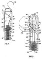
- Figure 1 is a schematic fragmentary enlarged longitudinal vertical sectional view of the distal end of a deployable implantable defibrillation electrode constructed in accordance with the present invention and with the fixation structure thereof in a spring biased retracted position in solid lines and a partially extended position in phantom lines;
- Figure 2 is a schematic plan view of a first form of the deployed defibrillation electrode utilizing the fixation structure of Figure 1;
- Figure 3 is a schematic plan view of a second form implantable defibrillation electrode in a deployed condition and wherein the fixation structure of Figure 1 is incorporated in an intermediate length portion of the electrode at the proximal end of the deployable distal end;
- Figure 4 is a side elevational view of a modified form of implantable defibrillation electrode fixation structure with portions of the tubular body of the electrode broken away and illustrated in section, the fixation hook thereof being in a retracted, shielded condition;
- Figure 4A is a distal end view of the structure illustrated in Figure 4 with alternate positions of the fixation hook shown in phantom lines;
- Figure 4B is a fragmentary elevational view similar to Figure 4 with the fixation hook being disposed in a fully extended position;
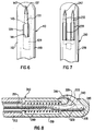
- Figure 5 is a schematic fragmentary enlarged longitudinal vertical sectional view similar to Figure 1, but illustrating a third form of fixation device;
- Figure 6 is a fragmentary top plan view of the fixation device shown in Figure 5,;
- Figure 7 is a fragmentary top plan view similar to Figure 6, but illustrating a double hook form of the device shown in Figure 6.; and
- Figure 8 is a schematic fragmentary enlarged longitudinal vertical sectional view similar to Figure 5, but illustrating fifth form of fixation device incorporating a reverse swingable hook.
- Referring now more specifically to Figures 1 and 2 of the drawings, there may be seen an internally deployable electro-catheter referred to in general by the
reference numeral 10 employing a deployabledistal end portion 12 and aproximal end portion 14. - The
distal end portion 12, in Figure 2, is illustrated in its deployed pre-configured flat zig-zag shape, the entire length of the electro-catheter being flexible and thedistal end portion 12 being capable of being straightened either through the use of an internal straightening stylet inserted thereinto from theproximal end portion 14 or an external flexible tubular catheter (not shown) of greater stiffness than thedistal end portion 12. - The precise electrical construction of the
deployable end portion 12 may be of any suitable well known type. Suffice it to say that through leads extending the length of the electro-catheter, electrical energy is delivered from a pulse generator to the cardiac tissue of the patient via the conductivedistal end portion 12 of the structure. - The terminal
distal end 16 comprises a dielectric (biocompatible polymer)tubular housing 19 and defines an endwise outwardly openingcylindrical cavity 18 into which thedistal end 20 of a helicaltubular spring 22 extending through thedistal end portion 12 projects, the proximal end (not shown) of thespring 22 being anchored relative to theproximal end portion 14 in any convenient manner. Thedistal end 20 includes a stretchable diametricallyenlarged portion 24 disposed within thecavity 18 terminating in a diametrically reducedterminal end 26 also disposed within thecavity 18. Theportion 24 comprises axial thrust developing means for yieldingly biasing theterminal end 26 in one direction. - The
base end 28 of a reverse turnedspring hook 30 is anchored to theterminal end 26 of thespring 22 and includes a reversed turnedhook 30 on itsfree end 32 substantially fully contained within thecavity 18. - After the electro-catheter has been inserted and positioned generally as desired for example the electro-catheter being inserted through the utilization of a tubular catheter, a fixation stylet (see Figure 4B) is associated with the
proximal end portion 14 and inserted through the electro-catheter 10 for engagement with the interior of theterminal end 26 of thespring 22 in which thebase end 28 of thespring hook 30 is anchored. The fixation stylet thereafter is actuated against theterminal end 26 in a fashion similar to a camera cable release to force the latter toward the open end of thecavity 18 to and past the phantom line position thereof illustrated in Figure 1 thus expanding the largediameter end portion 24 of thespring 22. Displacement of theterminal end 26 past the phantom line position of Figure 1 projects thebend 23 of the reversed turnedhook 32 from the open end of thecavity 18 for lateral displacement therefrom and engagement of thefree end 32 thereof with the tissue to which the terminaldistal end 16 is to be fixed. Then, the fixation stylet is released to enable retraction of thehook 30 from the phantom line position thereof to the solid line position thereof to thereby draw the exterior of the terminaldistal end 16 laterally into tight contact with the tissue engaged by thehook 30. - Thereafter, the fixation stylet may be removed and the tubular catheter may be withdrawn from about the
deployable end portion 12 to thereby enable the latter to deploy and assume the pre-configured shape thereof illustrated in Figure 2. - With attention now invited more specifically to Figure 3, a modified form of electro-catheter is referred to in general by the reference 10' incorporating a deployable distal end portion 12' and a proximal end portion 14'. The electro-catheter 10' is of a design to be inserted through the utilization of a tubular catheter and the deployable distal end portion 12' thereof is in the form of a flat spiral coil.
- The electro-catheter 10' incorporates a tubular housing 19' corresponding to the
tubular housing 19 defining thecavity 18. The housing 19' is serially disposed within the electro-catheter 10' between the proximal end portion 14' thereof and the deployable distal end portion 12' thereof. The internal structure of the housing 19' is substantially identical to the internal structure of thehousing 19 in that a helical tubular spring 22' corresponding to thespring 22 has its distal end 20' projecting into the cavity 18' of the housing 19' and the base end 28' of a spring hook 30' corresponding to thespring hook 30 is anchored in the terminal end 26' of the distal end 20', the distal end 20' including an enlarged diameter end portion 24' corresponding to theend portion 24. - The distal end portion 12' is, however, provided with a
slot 29 through which the free end 32' of the spring hook 30' may be extended upon utilization of a fixation stylet, for example, of the camera shutter cable release type herein above referred to. Accordingly, the housing 19' of the electro-catheter 10' may be laterally anchored to suitable internal tissues through the utilization of a fixation stylet. In this manner, an intermediate portion of the electro-catheter 10' can be affixed to body tissue after the distal active end of the electrode is permitted to deploy into the pre-configured shape illustrated in Figure 3. - With attention now invited to Figures 4, 4A and 4B, there may be seen a terminal distal end 16'' of an electro-catheter 10'' which may be considered as substantially identical to the electro-
catheter 10, except for the terminal distal end 16'' thereof. - The electro-catheter 10'' includes an internal coil spring 22'' corresponding to the
spring 20 equipped with a distal end 20'' incorporating an enlarged diameter end portion 24'' and a terminal end 26'', all of which are enclosed with a housing 19'', the distal terminal end of the housing 19'' being hollow and frusto conical as at 21 and provided with apartial spiral slot 23. The terminal distal end of housing 19'' is open as at 25 on its minor diameter end and the terminal end 26'' is projectable through theopen end 25 and includes anend enlargement 27 which is retractable only partly into theopen end 25. - The terminal end 26'' has the base end of a
curved hook 33 anchored thereto and thehook 33 projects outwardly through and is slidably received within theslot 23, theslot 23 extending less than 180 degrees about the terminaldistal end 21. - The housing 19'' may comprise the terminal distal end of an electro-catheter such as the electro-
catheter 10 in lieu of the terminaldistal end 19 thereof. The electro-catheter 10'' would be designed for insertion in the same manner as the electro-catheter 10 and fixed in the desired position prior to deployment of the deployable distal end portion 12'' of the electro-catheter 10'' corresponding to the deployabledistal end portion 12. - In order to affix the terminal distal end 16'', after the electro-catheter 10'' has been positioned utilizing routine implant techniques such as a tubular delivery catheter, a
fixation stylet 17, is inserted into the electro-catheter 10'' and associated with the proximal end portion thereof. Then, the fixation stylet is operated in a fashion similar to a camera cable release to lengthwise elongate the enlarged diameter end portion 24'' from the condition thereof illustrated in Figure 4 to the expanded condition thereof illustrated in Figure 4B, which movement causes thehook 33 to move from theend 37 of theslot 23 in which thehook 33 is retracted to theend 39 of theslot 23, in which position thehook 33 is fully extended, the terminal end 26'' being projected through theopen end 25 of the terminaldistal end 21. Thereafter, the fixation stylet may be released so that the spring biasing action of the enlarged diameter end portion 24'' may retract thehook 33 back through theslot 23 from theend 39 thereof to theend 37 thereof, during which movement thehook 33 engages adjacent tissue and laterally draws the terminaldistal end 21 toward and against that tissue and simultaneously draws the sharp point 33' into the outwardly openingrecess 45 shown in Figure 4. - After fixation of the electro-catheter 10'', the tubular delivery catheter (not shown) may be withdrawn to thereby allow the distal end portion 12'' to deploy and assume the pre-configured shape of the-
distal end portion 12 illustrated in Figure 2. - The
housings 19, 19' and 19'' are insulated from the electrical conductors (not shown) which bring electrical energy to conductive outer surface portions of thedistal end portions 12, 12' and 12''. Further, the phantom lines 41 and 41' indicate the structure of thedistal end portions 12 and 12', respectively, which comprise the spiral conductors disposed thereabout and which bring electrical energy to the outer surface portions of theend portions 12 and 12' (the electricity being supplied thereto through proximal lumen tubing or possible bilumen tubing with one lumen incorporating the electrical conductor leading to the conductors and the second lumen dedicated to operation of the fixation device). When thehook 33 is disposed in theend 37 of the slot 23 (subsequent to release of engagement of thehook 33 with organ tissue), it is positioned immediately forward of theshield 45 to thereby facilitate repositioning or removal of the electro-catheter 10'' subsequent to its usage. - With attention now invited more specifically to Figures 5 and 6, the numeral 110 generally designates an internally deployable electro-catheter similar to the electro-
catheter 10 illustrated in Figures 1 and 2. All components of thecatheter 110 corresponding to similar components of thecatheter 10 are referred by similar reference numerals in the one hundred series.Distal end portion 112 includes a dielectrictubular housing 119 in which thedistal end 120 of a helicaltubular spring 122 is disposed. Thedistal end 120 includes a strengthable diametrically enlarged portion 124 -disposed within ahollow cavity 118 formed in thehousing 119 and the diametricallyenlarged portion 124 terminates in a diametrically reducedterminal end 126 to which there is secured oneend 127 of athrust rod 129 through the utilization of asuitable fastener 121. The other end of therod 129 has one end one 131 of acurved hook 133 pivotally secured thereto as at 135 and the free end of thehook 133 is pointed as at 137. The free end portion of thehook 131 projects through aradial opening 139 formed in thehousing 119 and extending longitudinally thereof, thehousing 119 including cam surfaces 141 and 143 at the proximal and distal ends, respectively, of the opening orslot 139. - The diametrically reduced
terminal end 126 and therod 129 may be advanced toward the roundeddistal end 145 of thehousing 19 in the same manner in which theterminal end 26 may be advanced from the solid line position thereof in Figure 1 to the phantom line position thereof illustrated in Figure 1. - When the
rod 129 is in the retracted solid line position thereof illustrated in Figure 5, thehook 133 is fully retracted and has itspointed end 137 received within an outwardly openingnotch 147 formed in one side of thedistal end 145 of thehousing 119. However, when the diametrically reducedportion 126 and therod 129 are advanced toward thedistal end 145, thecam surface 143 swings thehook 133 in a counterclockwise direction as viewed in Figure 5 toward the lowermost extended position thereof illustrated in phantom lines. At this point, thehousing 119 is positioned adjacent the pericardial sack and the diametricallyreduced end portion 126 and therod 129 are then allowed to retract toward the proximal end of thehousing 119 where upon thehook 133 will hook engage the pericardial sack and swing toward the solid line position of the hook illustrated in Figure 5 thereby fixing thehousing 119 to the pericardial sack. - Figure 6 illustrates the
single hook 133 of the electro-catheter 110 illustrated in Figure 5 and Figure 7 illustrates a further modified form of electro-catheter 210 which is substantially identical to the electro-catheter 10, except that the electro-catheter 210 includes a pair of hooks orhook members 233 and a pair ofrecesses 247 in which to receive the free pointed ends of thehook members 233. In addition, thehousing 219 of the electro-catheter 210 includes a pair radial openings orslots 239 through which the hooks orhook members 233 operate. - The use two
hooks 233 as opposed to asingle hook 133 merely provides additional assurance against dislodgement of the fixation device. - Of course, the fixation devices illustrated in Figures 5-7 may be incorporated either at the distal end of a deployable defibrillator end portion such as the
end portion 12, or at the proximal end of a deployable end portion such as the end portion 12' illustrated in Figure 3. - With attention now invited more specifically to Figure 8, there may be seen yet a another form of deployable electro-catheter referred to in general by the
reference numeral 310 including a deployabledistal end portion 312. Thedeployable end portion 312 supports atubular housing 319 therefrom including a radial slot oropening 339 terminating at cam surfaces 341 and 343 corresponding to thesurfaces rod 329 is reciprocal within thehousing 319 corresponding to therod 129 and has a hook orhook member 333 pivotally mounted from the distal end thereof as at 335. Therod 329 is yieldingly biased toward thedistal end 345 of thehousing 319 by acompression spring 349 and retracted away from thedistal end 345 by a pull cord or the like 351. During movement of therod 329 from the solid line position thereof to a position retracted fully away from thedistal end portion 345, thehook 333 is cammed by thecam surface 341 to the phantom line position thereof illustrated in Figure 8, and when thespring 349 is allowed to shift therod 329 toward thedistal end portion 345, thehook 333 is pivoted from the phantom line position thereof illustrated in Figure 8 to the solid line position thereof. Of course, all of thefixation devices distal end portion 12 of the distal end portion 12'. - The foregoing is considered as illustrative only of the principles of the invention. Further, since numerous modifications and changes will readily occur to those skilled in the art, it is not desired to limit the invention to the exact construction and operation shown and described, and accordingly, all suitable modifications and equivalents may be resorted to, falling within the scope of the invention.
Claims (23)
- An implantable defibrillation electrode including a conductive distal end portion and a non-conductive proximal end portion, at least a major portion of the length of said distal end portion having a pre-configured shape and being resiliently deformable into a generally straight condition, said distal end portion including distal and proximal ends, at least one of said ends being hollow and having hook means shiftably supported therein for movement longitudinally thereof from a retracted position at least substantially entirely contained within said hollow end and an extended position at least substantially fully outwardly projected from said hollow end, means yieldingly biasing said hook means from said extended position toward said retracted position, said proximal end portion being hollow, and axial thrust developing means slidingly telescoped through said proximal end portion and operatively associated with said hook means for exerting an axial thrust thereon from the terminal end of said proximal end portion.
- The electrode of claim 1 wherein said one end comprises said distal end.
- The electrode of claim 1 wherein said one end comprises said proximal end.
- The electrode of claim 2 wherein said one end is hollow and includes a tubular terminal end housing opening endwise outwardly of said tubular end in which said hook means is at least substantially enclosed when in the retracted position thereof, said hook means including means, subsequent to partial extension of said hook means and prior to fully extension thereof, projecting the extended portion of said hook means laterally of said housing.
- The electrode of claim 3 wherein said distal end portion is hollow and said one end includes a tubular in-line housing in which said hook means is at least substantially enclosed when in the retracted position thereof and opening lengthwise along said distal end portion toward said distal end, said distal end portion including a longitudinal slot therein opening laterally outwardly therefrom through which said hook means is laterally projected when shifted to said extended position.
- The electrode of claim 1 wherein said one end comprises said distal end and includes a tubular end housing whose distal terminal end is tapered, said tapered distal end including a partial spiral slot formed therein, said hook means projecting at least slightly from the end of said slot adjacent the major dimension end of said tapered distal terminal end when said hook means is in said retracted position and being slidable along said slot toward the end of the latter adjacent the minor dimension end of said tapered distal terminal end as said hook means is shifted toward said extended position.
- The electrode of claim 1 wherein said hook means includes a reversed turned free end portion and a mounted base end portion, said hook means including a bend therein intermediate said free end portion and said base end portion contained within said hollow end when said hook means is in said retracted position and projectable outwardly of said hollow end when said hook means is in said extended position for lateral displacement of said hook means relative to said hollow end during final displacement of said hook means to said extended position.
- An implantable defibrillation electrode including a conductive distal end portion and a non-conductive proximal end portion, said distal end portion including distal and proximal ends, at least one of said ends being hollow and having hook means shiftably supported therein for movement longitudinally thereof from a retracted position at least substantially entirely contained within said hollow end and an extended position at least substantially fully outwardly projected from said hollow end, means yieldingly biasing said hook means from said extended position toward said retracted position, said proximal end portion being hollow, and axial thrust developing means slidingly telescoped through said proximal end portion and operatively associated with said hook means for exerting an axial thrust thereon from the terminal end of said proximal end portion.
- The electrode of claim 8 wherein at least a major portion of the length of said distal end portion has a pre-configured shape and is resiliently deformable into a generally straight condition.
- The electrode of claim 9 wherein said pre-configured shape comprises a spiral shape.
- The electrode of claim 10 wherein said pre-configured shape comprises a generally flat spiral shape.
- The electrode of claim 9 wherein said pre-configured shape comprises a generally flat zig-zag shape.
- The method of implanting an electrode in a body wherein the electrode includes a conductive distal end portion and a non-conductive proximal end portion with at least a major portion of the length of said distal end portion having a pre-configured shape and being resiliently deformable into a generally straight condition, said method including lengthwise introducing said electrode into said body through the utilization of a stiffening member operatively associated with the distal end portion in order to maintain the latter in a generally straightened condition and into position with said distal end portion positioned adjacent a predetermined body tissue area to which said distal end portion is to be attached, releasably anchoring said distal end portion to said predetermined body tissue area, and with withdrawing said stiffening member in order to deploy said distal end portion into its pre-configured shape.
- The method of claim 13 wherein said predetermined body tissue area comprises a pericardial tissue area.
- The method of implanting an electrode in a body wherein the electrode includes a conductive distal end portion and a non-conductive proximal end portion with at least a major portion of the length of said distal end portion having a pre-configured shape and being resiliently deformable into a generally straight condition, said method including lengthwise introducing said electrode into said body through the utilization of a stiffening member removably operatively associated with said distal end portion for maintaining the latter in a substantially straightened condition and into position with said distal end portion positioned adjacent a predetermined body tissue area to which said distal end portion is to be attached, at least partially removing said stiffening member in order to enable the deployment of said distal end portion into its pre-configured shape, and releasably anchoring said distal end portion to said predetermined body tissue area.
- The method of claim 15 wherein said predetermined body tissue area comprises a pericardial tissue area.
- The electrode of claim 1 wherein said one end comprises said distal end and includes a hollow conical terminal end including a spiral slot therein, said hook means being shiftable substantially axially of said hollow terminal end and extending substantially fully outward thereof when shifted toward the small diameter end thereof and being at least substantially fully enclosed within said hollow conical terminal end when shifted toward the large diameter end thereof.
- The electrode of claim 8 wherein said hook means includes an elongated rod longitudinally reciprocal within said hollow one end and having hook members means pivotally supported from the end of said rod remote from said proximal end, said one of said ends having longitudinal radial slot means therein through which said hook member means projects, the portions of said one of said ends defining the opposite ends of said slot means constituting cam surfaces operative to cam said hook means between extended and retracted positions upon movement of said rod toward and away from said proximal end, respectively.
- The defibrillation electrode of claim 18 wherein said hook member means includes a single hook member.
- The defibrillation electrode of claim 18 wherein said hook member means comprises a pair of laterally spaced hook members.
- The defibrillation electrode of claim 18 wherein said hook member means opens toward said distal end.
- The defibrillation electrode of claim 18 wherein said hook member means opens toward said proximal end.
- An implantable defibrillation electrode including a conductive distal end portion and a non-conductive proximal end portion, at least a major portion of the length of said distal end portion having a pre-configured shape and being resiliently deformable into a generally straight condition, said distal end portion including distal and proximal ends, at least one of said ends being hollow and having hook means shiftably supported therein for movement longitudinally thereof between a first position and a second position, said hook means including a sharp point received within recess means provided therefore in said housing when in said first position, means yieldingly biasing said hook means from said second position toward said first position, said proximal end portion being hollow, axial thrust developing means slidingly telescoped through said proximal end portion and operatively associated with said hook means for exerting an axial thrust thereon from the terminal end of said proximal end portion, said point, when said hook means is shifted from said first position toward said second position, being disposed for trailing movement relative to adjacent tissue and, when said hook means is shifted from said second position toward said first position being disposed for adjacent tissue penetrating movement, said recess means in which said sharp point is received when said hook means is in said first position serving to house said sharp point and to prevent further tissue penetration thereby subsequent to said sharp point penetrating adjacent tissue during movement of said hook means from said second position toward said first position.
Applications Claiming Priority (2)
| Application Number | Priority Date | Filing Date | Title |
|---|---|---|---|
| US07/888,492 US5314462A (en) | 1992-05-27 | 1992-05-27 | Positive fixation device |
| US888492 | 1992-05-27 |
Publications (3)
| Publication Number | Publication Date |
|---|---|
| EP0571985A2 true EP0571985A2 (en) | 1993-12-01 |
| EP0571985A3 EP0571985A3 (en) | 1995-02-15 |
| EP0571985B1 EP0571985B1 (en) | 1999-12-15 |
Family
ID=25393276
Family Applications (1)
| Application Number | Title | Priority Date | Filing Date |
|---|---|---|---|
| EP93108518A Expired - Lifetime EP0571985B1 (en) | 1992-05-27 | 1993-05-26 | Positive fixation device |
Country Status (7)
| Country | Link |
|---|---|
| US (3) | US5314462A (en) |
| EP (1) | EP0571985B1 (en) |
| JP (1) | JP3037529B2 (en) |
| AT (1) | ATE187656T1 (en) |
| AU (1) | AU658739B2 (en) |
| CA (1) | CA2097102C (en) |
| DE (1) | DE69327267T2 (en) |
Cited By (3)
| Publication number | Priority date | Publication date | Assignee | Title |
|---|---|---|---|---|
| WO1996040363A1 (en) * | 1995-06-07 | 1996-12-19 | Intermedics, Inc. | Transvenous defibrillation lead with side hooks |
| WO2003092801A1 (en) * | 2002-04-30 | 2003-11-13 | Medtronic, Inc. | Apparatus and method for fixedly engaging an implantable electrical lead |
| EP2379164B1 (en) * | 2008-12-19 | 2016-05-11 | St. Jude Medical AB | Implantable medical lead with a movable radiopaque marker |
Families Citing this family (126)
| Publication number | Priority date | Publication date | Assignee | Title |
|---|---|---|---|---|
| US5314462A (en) * | 1992-05-27 | 1994-05-24 | Cardiac Pacemakers, Inc. | Positive fixation device |
| US5496362A (en) * | 1992-11-24 | 1996-03-05 | Cardiac Pacemakers, Inc. | Implantable conformal coil patch electrode with multiple conductive elements for cardioversion and defibrillation |
| ES2135520T3 (en) * | 1993-11-04 | 1999-11-01 | Bard Inc C R | NON-MIGRANT VASCULAR PROSTHESIS. |
| US5476500A (en) * | 1993-12-20 | 1995-12-19 | Ventritex, Inc. | Endocardial lead system with defibrillation electrode fixation |
| US5776072A (en) * | 1995-12-28 | 1998-07-07 | Cardiac Pacemakers, Inc. | Discrimination of atrial and ventricular signals from a single cardiac lead |
| DE29603805U1 (en) * | 1996-03-01 | 1997-07-03 | Michel Ulrich Dipl Ing | Device for transvenous cardioversion of atrial fibrillation or atrial flutter |
| US5851226A (en) | 1996-10-22 | 1998-12-22 | Medtronic, Inc. | Temporary transvenous endocardial lead |
| US5860998A (en) * | 1996-11-25 | 1999-01-19 | C. R. Bard, Inc. | Deployment device for tubular expandable prosthesis |
| US5759202A (en) * | 1997-04-28 | 1998-06-02 | Sulzer Intermedics Inc. | Endocardial lead with lateral active fixation |
| US5769881A (en) * | 1997-05-22 | 1998-06-23 | Sulzer Intermedics Inc. | Endocardial lead with multiple branches |
| US5871532A (en) * | 1997-05-22 | 1999-02-16 | Sulzer Intermedics Inc. | Epicardial lead for minimally invasive implantation |
| US6501994B1 (en) | 1997-12-24 | 2002-12-31 | Cardiac Pacemakers, Inc. | High impedance electrode tip |
| US6085119A (en) | 1998-07-22 | 2000-07-04 | Cardiac Pacemakers, Inc. | Single pass endocardial lead for multi-site atrial pacing |
| US6097986A (en) * | 1997-12-17 | 2000-08-01 | Cardiac Pacemakers, Inc. | Retractable lead with mesh screen |
| US6321122B1 (en) | 1998-07-22 | 2001-11-20 | Cardiac Pacemakers, Inc. | Single pass defibrillation/pacing lead with passively attached electrode for pacing and sensing |
| US6152954A (en) | 1998-07-22 | 2000-11-28 | Cardiac Pacemakers, Inc. | Single pass lead having retractable, actively attached electrode for pacing and sensing |
| US6212434B1 (en) | 1998-07-22 | 2001-04-03 | Cardiac Pacemakers, Inc. | Single pass lead system |
| US6055457A (en) * | 1998-03-13 | 2000-04-25 | Medtronic, Inc. | Single pass A-V lead with active fixation device |
| US6108582A (en) | 1998-07-02 | 2000-08-22 | Intermedics Inc. | Cardiac pacemaker lead with extendable/retractable fixation |
| US6463334B1 (en) | 1998-11-02 | 2002-10-08 | Cardiac Pacemakers, Inc. | Extendable and retractable lead |
| US6501990B1 (en) | 1999-12-23 | 2002-12-31 | Cardiac Pacemakers, Inc. | Extendable and retractable lead having a snap-fit terminal connector |
| ES2230826T3 (en) | 1999-04-02 | 2005-05-01 | Sorin Biomedica Crm S.R.L. | ANCHORAGE STRUCTURE FOR IMPLANTABLE ELECTRODES. |
| US6353762B1 (en) * | 1999-04-30 | 2002-03-05 | Medtronic, Inc. | Techniques for selective activation of neurons in the brain, spinal cord parenchyma or peripheral nerve |
| US20050102003A1 (en) * | 2000-05-03 | 2005-05-12 | Grabek James R. | Perficardial pacing lead placement device and method |
| US6745079B2 (en) * | 2001-11-07 | 2004-06-01 | Medtronic, Inc. | Electrical tissue stimulation apparatus and method |
| DE10162508A1 (en) * | 2001-12-19 | 2003-07-03 | Biotronik Mess & Therapieg | Epicardial lead, insertion catheter for such and electrode implantation set |
| US7588581B2 (en) * | 2002-03-26 | 2009-09-15 | Medtronic, Inc. | Placement of chronic micro-catheter device and method |
| US7731655B2 (en) * | 2002-09-20 | 2010-06-08 | Id, Llc | Tissue retractor and method for using the retractor |
| US20070010715A1 (en) * | 2002-09-20 | 2007-01-11 | Id, Llc | Tissue retractor and method for using the retractor |
| US7392094B2 (en) | 2002-12-19 | 2008-06-24 | Cardiac Pacemakers, Inc. | Implantable lead for septal placement of pacing electrodes |
| US7890188B2 (en) * | 2002-12-19 | 2011-02-15 | Cardiac Pacemakers, Inc. | Implantable lead for septal placement of electrode with fixation mechanism in the pulmonary artery |
| US20040122498A1 (en) * | 2002-12-19 | 2004-06-24 | Yongxing Zhang | Pulmonary artery lead for atrial therapy |
| US20040260374A1 (en) * | 2002-12-19 | 2004-12-23 | Cardiac Pacemakers, Inc. | Implantable lead with fixation mechanism in the pulmonary artery |
| US7555351B2 (en) * | 2002-12-19 | 2009-06-30 | Cardiac Pacemakers, Inc. | Pulmonary artery lead for atrial therapy and atrial pacing and sensing |
| DE10316177B4 (en) * | 2003-04-10 | 2007-05-31 | Cardiac Pacemakers, Inc., St. Paul | Pacemaker electrode arrangement |
| DE10323016A1 (en) * | 2003-05-15 | 2004-12-02 | Biotronik Meß- und Therapiegeräte GmbH & Co. Ingenieurbüro Berlin | Epicardium electrode |
| WO2005039691A1 (en) * | 2003-10-24 | 2005-05-06 | Cardiac Pacemakers, Inc. | Myocardial lead attachment system |
| US7499759B2 (en) * | 2003-10-24 | 2009-03-03 | Cardiac Pacemakers, Inc. | Distal or proximal fixation of over-the-tether myocardial leads |
| US20050125050A1 (en) * | 2003-12-04 | 2005-06-09 | Wilson Cook Medical Incorporated | Biliary stent introducer system |
| US7828802B2 (en) * | 2004-01-16 | 2010-11-09 | Expanding Orthopedics, Inc. | Bone fracture treatment devices and methods of their use |
| JP4714736B2 (en) * | 2004-03-31 | 2011-06-29 | ウィルソン−クック・メディカル・インコーポレーテッド | Stent introducer system |
| US7308319B2 (en) * | 2004-10-21 | 2007-12-11 | Cardiac Pacemakers, Inc. | Delivery system and method using pulmonary artery for placement of RV leads |
| US20060089694A1 (en) * | 2004-10-21 | 2006-04-27 | Cardiac Pacemakers, Inc. | Delivery system and method for pulmonary artery leads |
| US7463932B2 (en) * | 2005-01-14 | 2008-12-09 | Cardiac Pacemakers, Inc. | Fastening device for an epicardial lead |
| US7587238B2 (en) * | 2005-03-11 | 2009-09-08 | Cardiac Pacemakers, Inc. | Combined neural stimulation and cardiac resynchronization therapy |
| US7840266B2 (en) * | 2005-03-11 | 2010-11-23 | Cardiac Pacemakers, Inc. | Integrated lead for applying cardiac resynchronization therapy and neural stimulation therapy |
| US7330765B2 (en) * | 2005-04-25 | 2008-02-12 | Cardiac Pacemakers, Inc. | Cardiac lead having self-expanding fixation features |
| US7477946B2 (en) * | 2005-04-26 | 2009-01-13 | Cardiac Pacemakers, Inc. | Fixation device for coronary venous lead |
| US8175724B2 (en) * | 2005-04-26 | 2012-05-08 | Cardiac Pacemakers, Inc. | Vascular fixation device |
| WO2006117783A2 (en) * | 2005-05-02 | 2006-11-09 | Resqmedical Ltd. | Self-withdrawing catheter for injecting into body passageways and kit containing same |
| US7272448B1 (en) | 2005-05-24 | 2007-09-18 | Pacesetter, Inc. | Medical lead for placement in the pericardial sac |
| US20070123923A1 (en) * | 2005-11-30 | 2007-05-31 | Lindstrom Curtis C | Implantable medical device minimizing rotation and dislocation |
| US8219213B2 (en) * | 2005-12-30 | 2012-07-10 | Medtronic, Inc. | Active fixation cardiac vein medical lead |
| US8160722B2 (en) * | 2006-02-28 | 2012-04-17 | Medtronic, Inc. | Subcutaneous lead fixation mechanisms |
| US7899555B2 (en) * | 2006-04-11 | 2011-03-01 | Pacesetter, Inc. | Intrapericardial lead |
| US8244379B2 (en) * | 2006-04-26 | 2012-08-14 | Medtronic, Inc. | Pericardium fixation concepts of epicardium pacing leads and tools |
| US8406901B2 (en) * | 2006-04-27 | 2013-03-26 | Medtronic, Inc. | Sutureless implantable medical device fixation |
| US7848821B1 (en) * | 2006-07-11 | 2010-12-07 | Pacesetter, Inc. | Apparatus and method for electrode insertion in heart tissue |
| US8036757B2 (en) * | 2006-09-10 | 2011-10-11 | Seth Worley | Pacing lead and method for pacing in the pericardial space |
| US7865249B2 (en) * | 2006-09-22 | 2011-01-04 | Cardiac Pacemakers, Inc. | Means to securely fixate pacing leads and/or sensors in vessels |
| US7765012B2 (en) * | 2006-11-30 | 2010-07-27 | Medtronic, Inc. | Implantable medical device including a conductive fixation element |
| US9492657B2 (en) * | 2006-11-30 | 2016-11-15 | Medtronic, Inc. | Method of implanting a medical device including a fixation element |
| US7949411B1 (en) | 2007-01-23 | 2011-05-24 | Pacesetter, Inc. | Epicardial lead |
| US7920928B1 (en) | 2007-01-31 | 2011-04-05 | Pacesetter, Inc. | Passive fixation for epicardial lead |
| EP2131908A2 (en) * | 2007-02-28 | 2009-12-16 | Medtronic, Inc. | Implantable medical device system with fixation member |
| US8000810B2 (en) * | 2007-03-20 | 2011-08-16 | Cardiac Pacemakers, Inc. | Systems and methods for transvenous lead implantation |
| US20090082838A1 (en) * | 2007-09-26 | 2009-03-26 | Cardiac Pacemakers, Inc. | Left-ventricular lead fixation device in coronary veins |
| US8086324B1 (en) | 2007-09-27 | 2011-12-27 | Pacesetter, Inc. | Intrapericardial lead with distal region configured to optimize lead extraction |
| US9034002B2 (en) * | 2008-02-18 | 2015-05-19 | Covidien Lp | Lock bar spring and clip for implant deployment device |
| US9393093B2 (en) | 2008-02-18 | 2016-07-19 | Covidien Lp | Clip for implant deployment device |
| US9023063B2 (en) | 2008-04-17 | 2015-05-05 | Apollo Endosurgery, Inc. | Implantable access port device having a safety cap |
| US9023062B2 (en) | 2008-04-17 | 2015-05-05 | Apollo Endosurgery, Inc. | Implantable access port device and attachment system |
| KR100996859B1 (en) * | 2008-10-29 | 2010-11-26 | 충북대학교 산학협력단 | A probe for electric stimulator having a variable vaginal electrode |
| US8515558B1 (en) * | 2008-11-21 | 2013-08-20 | Greatbatch Ltd. | Anchoring mechanism for an implantable stimulation lead |
| US20100256696A1 (en) | 2009-04-07 | 2010-10-07 | Boston Scientific Neuromodulation Corporation | Anchoring Units For Implantable Electrical Stimulation Systems And Methods Of Making And Using |
| US8715158B2 (en) | 2009-08-26 | 2014-05-06 | Apollo Endosurgery, Inc. | Implantable bottom exit port |
| US8708979B2 (en) | 2009-08-26 | 2014-04-29 | Apollo Endosurgery, Inc. | Implantable coupling device |
| US8506532B2 (en) | 2009-08-26 | 2013-08-13 | Allergan, Inc. | System including access port and applicator tool |
| EP2327366B1 (en) * | 2009-11-30 | 2012-03-14 | Sorin CRM SAS | Kit for piercing the cardiac septum and implanting a transseptal probe, in particular a probe for detection/stimulation of a left cavity of the heart |
| US8882728B2 (en) | 2010-02-10 | 2014-11-11 | Apollo Endosurgery, Inc. | Implantable injection port |
| US20110270021A1 (en) | 2010-04-30 | 2011-11-03 | Allergan, Inc. | Electronically enhanced access port for a fluid filled implant |
| US20110270025A1 (en) | 2010-04-30 | 2011-11-03 | Allergan, Inc. | Remotely powered remotely adjustable gastric band system |
| US8992415B2 (en) | 2010-04-30 | 2015-03-31 | Apollo Endosurgery, Inc. | Implantable device to protect tubing from puncture |
| US20120041258A1 (en) | 2010-08-16 | 2012-02-16 | Allergan, Inc. | Implantable access port system |
| US20120065460A1 (en) | 2010-09-14 | 2012-03-15 | Greg Nitka | Implantable access port system |
| US10112045B2 (en) | 2010-12-29 | 2018-10-30 | Medtronic, Inc. | Implantable medical device fixation |
| US9775982B2 (en) | 2010-12-29 | 2017-10-03 | Medtronic, Inc. | Implantable medical device fixation |
| US8821373B2 (en) | 2011-05-10 | 2014-09-02 | Apollo Endosurgery, Inc. | Directionless (orientation independent) needle injection port |
| US8801597B2 (en) | 2011-08-25 | 2014-08-12 | Apollo Endosurgery, Inc. | Implantable access port with mesh attachment rivets |
| US9817494B2 (en) * | 2011-09-12 | 2017-11-14 | Mediatek Inc. | Method for converting control input of input domain into control output of control domain using variable control resolution technique, and related control apparatus thereof |
| US9199069B2 (en) | 2011-10-20 | 2015-12-01 | Apollo Endosurgery, Inc. | Implantable injection port |
| US8858421B2 (en) | 2011-11-15 | 2014-10-14 | Apollo Endosurgery, Inc. | Interior needle stick guard stems for tubes |
| US9089395B2 (en) | 2011-11-16 | 2015-07-28 | Appolo Endosurgery, Inc. | Pre-loaded septum for use with an access port |
| US9339197B2 (en) | 2012-03-26 | 2016-05-17 | Medtronic, Inc. | Intravascular implantable medical device introduction |
| US10485435B2 (en) | 2012-03-26 | 2019-11-26 | Medtronic, Inc. | Pass-through implantable medical device delivery catheter with removeable distal tip |
| US9717421B2 (en) | 2012-03-26 | 2017-08-01 | Medtronic, Inc. | Implantable medical device delivery catheter with tether |
| US9854982B2 (en) | 2012-03-26 | 2018-01-02 | Medtronic, Inc. | Implantable medical device deployment within a vessel |
| US9220906B2 (en) | 2012-03-26 | 2015-12-29 | Medtronic, Inc. | Tethered implantable medical device deployment |
| US9833625B2 (en) | 2012-03-26 | 2017-12-05 | Medtronic, Inc. | Implantable medical device delivery with inner and outer sheaths |
| US9351648B2 (en) | 2012-08-24 | 2016-05-31 | Medtronic, Inc. | Implantable medical device electrode assembly |
| AU2014265849A1 (en) | 2013-05-14 | 2015-11-12 | Boston Scientific Neuromodulation Corporation | Electrical stimulation leads with anchoring unit and electrode arrangement and methods of making and using |
| US10071243B2 (en) | 2013-07-31 | 2018-09-11 | Medtronic, Inc. | Fixation for implantable medical devices |
| ES2666373T3 (en) | 2013-08-16 | 2018-05-04 | Cardiac Pacemakers, Inc. | Management devices for wireless heart devices |
| US10179236B2 (en) | 2013-08-16 | 2019-01-15 | Cardiac Pacemakers, Inc. | Leadless cardiac pacing devices |
| WO2015023474A1 (en) | 2013-08-16 | 2015-02-19 | Cardiac Pacemakers, Inc. | Leadless cardiac pacemaker and retrieval device |
| US10842993B2 (en) | 2013-08-16 | 2020-11-24 | Cardiac Pacemakers, Inc. | Leadless cardiac pacing devices |
| US9393427B2 (en) | 2013-08-16 | 2016-07-19 | Cardiac Pacemakers, Inc. | Leadless cardiac pacemaker with delivery and/or retrieval features |
| US10722723B2 (en) | 2013-08-16 | 2020-07-28 | Cardiac Pacemakers, Inc. | Delivery devices and methods for leadless cardiac devices |
| US9480850B2 (en) | 2013-08-16 | 2016-11-01 | Cardiac Pacemakers, Inc. | Leadless cardiac pacemaker and retrieval device |
| US9492674B2 (en) | 2013-08-16 | 2016-11-15 | Cardiac Pacemakers, Inc. | Leadless cardiac pacemaker with delivery and/or retrieval features |
| US9669210B2 (en) | 2014-04-22 | 2017-06-06 | Boston Scientific Neuromodulation Corporation | Electrical stimulation leads and systems with folding anchoring units and methods of making and using |
| WO2015168153A1 (en) | 2014-04-29 | 2015-11-05 | Cardiac Pacemakers, Inc. | Leadless cardiac pacing devices including tissue engagement verification |
| US9795781B2 (en) | 2014-04-29 | 2017-10-24 | Cardiac Pacemakers, Inc. | Leadless cardiac pacemaker with retrieval features |
| US9649489B2 (en) | 2014-06-02 | 2017-05-16 | Boston Scientific Neuromodulation Corporation | Electrical stimulation leads and systems with anchoring units having struts and methods of making and using |
| US9533141B2 (en) * | 2014-07-07 | 2017-01-03 | Boston Scientific Neuromodulation Corporation | Electrical stimulation leads and systems with elongate anchoring elements |
| US9764127B2 (en) | 2014-12-19 | 2017-09-19 | Cardiac Pacemakers, Inc. | Medical lead anchoring |
| EP3380017A4 (en) | 2015-11-25 | 2019-11-27 | Talon Medical, LLC | Tissue engagement devices, systems, and methods |
| US10099050B2 (en) | 2016-01-21 | 2018-10-16 | Medtronic, Inc. | Interventional medical devices, device systems, and fixation components thereof |
| US10463853B2 (en) | 2016-01-21 | 2019-11-05 | Medtronic, Inc. | Interventional medical systems |
| US20190240481A1 (en) * | 2016-10-17 | 2019-08-08 | Atrium Health | Devices, systems, and methods for treating cardiac arrhythmias |
| CN110870948B (en) * | 2018-08-31 | 2021-11-05 | 创领心律管理医疗器械(上海)有限公司 | Delivery device, cardiac pacing device and fixing structure thereof |
| US10874850B2 (en) | 2018-09-28 | 2020-12-29 | Medtronic, Inc. | Impedance-based verification for delivery of implantable medical devices |
| US11759632B2 (en) | 2019-03-28 | 2023-09-19 | Medtronic, Inc. | Fixation components for implantable medical devices |
| DE102019111021A1 (en) * | 2019-04-29 | 2020-10-29 | Biotronik Se & Co. Kg | Retractable and retractable fixing element for fixing electrodes in blood vessels |
| US11331475B2 (en) | 2019-05-07 | 2022-05-17 | Medtronic, Inc. | Tether assemblies for medical device delivery systems |
| US20220096850A1 (en) * | 2020-09-30 | 2022-03-31 | Medtronic, Inc. | Deployable structures to anchor implanted devices |
Citations (11)
| Publication number | Priority date | Publication date | Assignee | Title |
|---|---|---|---|---|
| US3814104A (en) | 1971-07-05 | 1974-06-04 | W Irnich | Pacemaker-electrode |
| US4013690A (en) | 1974-02-05 | 1977-03-22 | Sandoz Ltd. | Organic compounds |
| US4058128A (en) | 1976-08-26 | 1977-11-15 | Frank Howard A | Electrode |
| US4142530A (en) | 1978-03-06 | 1979-03-06 | Vitatron Medical B. V. | Epicardial lead |
| US4233992A (en) | 1977-07-19 | 1980-11-18 | Bisping Hans Juergen | Implantable electrode |
| US4357946A (en) | 1980-03-24 | 1982-11-09 | Medtronic, Inc. | Epicardial pacing lead with stylet controlled helical fixation screw |
| US4378023A (en) | 1980-05-29 | 1983-03-29 | Trabucco Hector O | Percutaneous insertable electrode device for the transitory or permanent stimulation of the heart or other organs and a method for implanting it |
| US4624265A (en) | 1985-07-24 | 1986-11-25 | Ge. Sv. In. S.R.L. | Electro-catheter used in physiological cardiac stimulation simulative of the auriculo-ventricular sequence, featuring active engagement of the cardiac muscle |
| US4649938A (en) | 1985-04-29 | 1987-03-17 | Mcarthur William A | Tissue-stimulating electrode having sealed, low-friction extendable/retractable active fixation means |
| US4858623A (en) | 1987-07-13 | 1989-08-22 | Intermedics, Inc. | Active fixation mechanism for lead assembly of an implantable cardiac stimulator |
| US4860760A (en) | 1986-05-15 | 1989-08-29 | Omron Tateisi Electronics Co. | Electronic blood pressure meter incorporating compensation function for systolic and diastolic blood pressure determinations |
Family Cites Families (22)
| Publication number | Priority date | Publication date | Assignee | Title |
|---|---|---|---|---|
| US3580242A (en) * | 1968-04-01 | 1971-05-25 | George E La Croix | Fetal scalp electrode unit |
| US3844292A (en) * | 1972-06-09 | 1974-10-29 | Medtronic Inc | Intravascular lead assembly |
| DE2309749B2 (en) * | 1973-02-27 | 1978-05-24 | Siegfried Dr.Med. Dipl.-Ing. Dipl.-Wirtsch.-Ing. Lehr | Electrode for medical purposes |
| DE2736275A1 (en) * | 1977-08-11 | 1979-02-22 | Walter Koglek | Heart pacemaker electrode with flexible hollow cable - is fastened to tissue by spring hooks retracted into sleeve by string |
| EP0004967A3 (en) * | 1978-04-17 | 1979-11-14 | Mohl, Werner, Prof. DDr. | Anchoring means for a probe head, particularly a cardiac probe |
| US4282885A (en) * | 1978-08-21 | 1981-08-11 | Bisping Hans Juergen | Electrode for implantation in the heart |
| SE434460B (en) * | 1979-06-14 | 1984-07-30 | Bertil Reenstierna | ENDOCARDIAL, IMPLANTABLE CORD FOR THE HEART STIMULATOR |
| DE2931643A1 (en) * | 1979-08-01 | 1981-02-19 | Biotronik Mess & Therapieg | Pacemaker electrode with dome-shaped wire-claws at front end - uses remotely-operated piston to open claws when correctly located |
| US4401126A (en) * | 1981-02-13 | 1983-08-30 | Bertil Reenstierna | Endocardial, implantable lead for pacemaker |
| US4567900A (en) * | 1984-06-04 | 1986-02-04 | Moore J Paul | Internal deployable defibrillator electrode |
| USH356H (en) * | 1985-02-27 | 1987-11-03 | Medtronic, Inc. | Epicardial lead having low threshold, low polarization myocardial electrode |
| US5007436A (en) * | 1985-06-20 | 1991-04-16 | Medtronic, Inc. | Cardioversion and defibrillation lead system |
| US4860769A (en) * | 1987-11-12 | 1989-08-29 | Thomas J. Fogarty | Implantable defibrillation electrode |
| US4865037A (en) * | 1987-11-13 | 1989-09-12 | Thomas J. Fogarty | Method for implanting automatic implantable defibrillator |
| US4946457A (en) * | 1987-12-03 | 1990-08-07 | Dimed, Incorporated | Defibrillator system with cardiac leads and method for transvenous implantation |
| US5052407A (en) * | 1988-04-14 | 1991-10-01 | Mieczyslaw Mirowski | Cardiac defibrillation/cardioversion spiral patch electrode |
| JPH02307481A (en) * | 1989-05-08 | 1990-12-20 | Intermedics Inc | Positive fixing mechanism for lead assembly of buried cardiotonic device |
| US5144960A (en) * | 1991-03-20 | 1992-09-08 | Medtronic, Inc. | Transvenous defibrillation lead and method of use |
| US5179962A (en) * | 1991-06-20 | 1993-01-19 | Possis Medical, Inc. | Cardiac lead with retractible fixators |
| WO1993011289A1 (en) * | 1991-11-26 | 1993-06-10 | E.I. Du Pont De Nemours And Company | A method for ply-twisting yarns without balloon limiters |
| US5259395A (en) * | 1992-01-15 | 1993-11-09 | Siemens Pacesetter, Inc. | Pacemaker lead with extendable retractable lockable fixing helix |
| US5314462A (en) * | 1992-05-27 | 1994-05-24 | Cardiac Pacemakers, Inc. | Positive fixation device |
-
1992
- 1992-05-27 US US07/888,492 patent/US5314462A/en not_active Expired - Lifetime
-
1993
- 1993-05-26 AU AU39847/93A patent/AU658739B2/en not_active Ceased
- 1993-05-26 DE DE69327267T patent/DE69327267T2/en not_active Expired - Lifetime
- 1993-05-26 EP EP93108518A patent/EP0571985B1/en not_active Expired - Lifetime
- 1993-05-26 AT AT93108518T patent/ATE187656T1/en not_active IP Right Cessation
- 1993-05-27 CA CA002097102A patent/CA2097102C/en not_active Expired - Fee Related
- 1993-05-27 JP JP5126321A patent/JP3037529B2/en not_active Expired - Fee Related
- 1993-12-29 US US08/174,919 patent/US5425756A/en not_active Expired - Lifetime
-
1995
- 1995-02-03 US US08/383,329 patent/US5514174A/en not_active Expired - Lifetime
Patent Citations (11)
| Publication number | Priority date | Publication date | Assignee | Title |
|---|---|---|---|---|
| US3814104A (en) | 1971-07-05 | 1974-06-04 | W Irnich | Pacemaker-electrode |
| US4013690A (en) | 1974-02-05 | 1977-03-22 | Sandoz Ltd. | Organic compounds |
| US4058128A (en) | 1976-08-26 | 1977-11-15 | Frank Howard A | Electrode |
| US4233992A (en) | 1977-07-19 | 1980-11-18 | Bisping Hans Juergen | Implantable electrode |
| US4142530A (en) | 1978-03-06 | 1979-03-06 | Vitatron Medical B. V. | Epicardial lead |
| US4357946A (en) | 1980-03-24 | 1982-11-09 | Medtronic, Inc. | Epicardial pacing lead with stylet controlled helical fixation screw |
| US4378023A (en) | 1980-05-29 | 1983-03-29 | Trabucco Hector O | Percutaneous insertable electrode device for the transitory or permanent stimulation of the heart or other organs and a method for implanting it |
| US4649938A (en) | 1985-04-29 | 1987-03-17 | Mcarthur William A | Tissue-stimulating electrode having sealed, low-friction extendable/retractable active fixation means |
| US4624265A (en) | 1985-07-24 | 1986-11-25 | Ge. Sv. In. S.R.L. | Electro-catheter used in physiological cardiac stimulation simulative of the auriculo-ventricular sequence, featuring active engagement of the cardiac muscle |
| US4860760A (en) | 1986-05-15 | 1989-08-29 | Omron Tateisi Electronics Co. | Electronic blood pressure meter incorporating compensation function for systolic and diastolic blood pressure determinations |
| US4858623A (en) | 1987-07-13 | 1989-08-22 | Intermedics, Inc. | Active fixation mechanism for lead assembly of an implantable cardiac stimulator |
Cited By (4)
| Publication number | Priority date | Publication date | Assignee | Title |
|---|---|---|---|---|
| WO1996040363A1 (en) * | 1995-06-07 | 1996-12-19 | Intermedics, Inc. | Transvenous defibrillation lead with side hooks |
| WO2003092801A1 (en) * | 2002-04-30 | 2003-11-13 | Medtronic, Inc. | Apparatus and method for fixedly engaging an implantable electrical lead |
| US7076309B2 (en) | 2002-04-30 | 2006-07-11 | Medtronic, Inc. | Apparatus and method for fixedly engaging an electrical lead |
| EP2379164B1 (en) * | 2008-12-19 | 2016-05-11 | St. Jude Medical AB | Implantable medical lead with a movable radiopaque marker |
Also Published As
| Publication number | Publication date |
|---|---|
| DE69327267T2 (en) | 2000-08-03 |
| ATE187656T1 (en) | 2000-01-15 |
| US5425756A (en) | 1995-06-20 |
| US5314462A (en) | 1994-05-24 |
| DE69327267D1 (en) | 2000-01-20 |
| EP0571985A3 (en) | 1995-02-15 |
| CA2097102A1 (en) | 1993-11-28 |
| JP3037529B2 (en) | 2000-04-24 |
| US5514174A (en) | 1996-05-07 |
| AU3984793A (en) | 1993-12-16 |
| AU658739B2 (en) | 1995-04-27 |
| JPH06169997A (en) | 1994-06-21 |
| CA2097102C (en) | 1998-09-01 |
| EP0571985B1 (en) | 1999-12-15 |
Similar Documents
| Publication | Publication Date | Title |
|---|---|---|
| US5425756A (en) | Positive fixation device | |
| US5300106A (en) | Insertion and tunneling tool for a subcutaneous wire patch electrode | |
| EP1682215B1 (en) | Myocardial lead attachment system | |
| US11219760B2 (en) | Compact implantable medical device and delivery device | |
| US7496410B2 (en) | Spring fixation mechanism for epicardial leads | |
| US8043126B2 (en) | Deployable medical lead fixation system and method | |
| US5020545A (en) | Cardiac lead assembly and method of attaching a cardiac lead assembly | |
| US4991578A (en) | Method and system for implanting self-anchoring epicardial defibrillation electrodes | |
| US4235246A (en) | Epicardial heart lead and assembly and method for optimal fixation of same for cardiac pacing | |
| US5228455A (en) | Implant tool for extendable/retractable positive fixation lead | |
| US4010758A (en) | Bipolar body tissue electrode | |
| US9108043B2 (en) | Bipolar screw-in lead | |
| US20030114908A1 (en) | Epicardial electrode lead, introducer for such a lead and set of instruments for electrode implantaion | |
| US20110251661A1 (en) | Lead fixation and extraction | |
| EP0570712A1 (en) | Electrode arrangement | |
| US4299239A (en) | Epicardial heart lead assembly | |
| JPH09508539A (en) | Floating myocardial electrode for implantable pulse generator | |
| GB2032278A (en) | Device for use in heart pacer electrode fixation | |
| US10111686B2 (en) | Device for the transcutaneous implantation of epicardial pacemaker electrodes | |
| EP3866911B1 (en) | Implantable electrode lead with active fixation |
Legal Events
| Date | Code | Title | Description |
|---|---|---|---|
| PUAI | Public reference made under article 153(3) epc to a published international application that has entered the european phase |
Free format text: ORIGINAL CODE: 0009012 |
|
| AK | Designated contracting states |
Kind code of ref document: A2 Designated state(s): AT BE CH DE DK ES FR GB GR IE IT LI LU MC NL PT SE |
|
| RIN1 | Information on inventor provided before grant (corrected) |
Inventor name: KENKNIGHT, BRUCE H. Inventor name: WICKHAM, ROBERT W., JR. Inventor name: HEIL, RONALD W., JR. |
|
| PUAL | Search report despatched |
Free format text: ORIGINAL CODE: 0009013 |
|
| AK | Designated contracting states |
Kind code of ref document: A3 Designated state(s): AT BE CH DE DK ES FR GB GR IE IT LI LU MC NL PT SE |
|
| 17P | Request for examination filed |
Effective date: 19950403 |
|
| 17Q | First examination report despatched |
Effective date: 19970623 |
|
| GRAG | Despatch of communication of intention to grant |
Free format text: ORIGINAL CODE: EPIDOS AGRA |
|
| GRAG | Despatch of communication of intention to grant |
Free format text: ORIGINAL CODE: EPIDOS AGRA |
|
| GRAH | Despatch of communication of intention to grant a patent |
Free format text: ORIGINAL CODE: EPIDOS IGRA |
|
| GRAH | Despatch of communication of intention to grant a patent |
Free format text: ORIGINAL CODE: EPIDOS IGRA |
|
| GRAA | (expected) grant |
Free format text: ORIGINAL CODE: 0009210 |
|
| AK | Designated contracting states |
Kind code of ref document: B1 Designated state(s): AT BE CH DE DK ES FR GB GR IE IT LI LU MC NL PT SE |
|
| PG25 | Lapsed in a contracting state [announced via postgrant information from national office to epo] |
Ref country code: SE Free format text: THE PATENT HAS BEEN ANNULLED BY A DECISION OF A NATIONAL AUTHORITY Effective date: 19991215 Ref country code: NL Free format text: LAPSE BECAUSE OF FAILURE TO SUBMIT A TRANSLATION OF THE DESCRIPTION OR TO PAY THE FEE WITHIN THE PRESCRIBED TIME-LIMIT Effective date: 19991215 Ref country code: LI Free format text: LAPSE BECAUSE OF FAILURE TO SUBMIT A TRANSLATION OF THE DESCRIPTION OR TO PAY THE FEE WITHIN THE PRESCRIBED TIME-LIMIT Effective date: 19991215 Ref country code: IT Free format text: LAPSE BECAUSE OF FAILURE TO SUBMIT A TRANSLATION OF THE DESCRIPTION OR TO PAY THE FEE WITHIN THE PRE;WARNING: LAPSES OF ITALIAN PATENTS WITH EFFECTIVE DATE BEFORE 2007 MAY HAVE OCCURRED AT ANY TIME BEFORE 2007. THE CORRECT EFFECTIVE DATE MAY BE DIFFERENT FROM THE ONE RECORDED.SCRIBED TIME-LIMIT Effective date: 19991215 Ref country code: GR Free format text: LAPSE BECAUSE OF NON-PAYMENT OF DUE FEES Effective date: 19991215 Ref country code: ES Free format text: THE PATENT HAS BEEN ANNULLED BY A DECISION OF A NATIONAL AUTHORITY Effective date: 19991215 Ref country code: CH Free format text: LAPSE BECAUSE OF FAILURE TO SUBMIT A TRANSLATION OF THE DESCRIPTION OR TO PAY THE FEE WITHIN THE PRESCRIBED TIME-LIMIT Effective date: 19991215 Ref country code: BE Free format text: LAPSE BECAUSE OF FAILURE TO SUBMIT A TRANSLATION OF THE DESCRIPTION OR TO PAY THE FEE WITHIN THE PRESCRIBED TIME-LIMIT Effective date: 19991215 Ref country code: AT Free format text: LAPSE BECAUSE OF FAILURE TO SUBMIT A TRANSLATION OF THE DESCRIPTION OR TO PAY THE FEE WITHIN THE PRESCRIBED TIME-LIMIT Effective date: 19991215 |
|
| REF | Corresponds to: |
Ref document number: 187656 Country of ref document: AT Date of ref document: 20000115 Kind code of ref document: T |
|
| REG | Reference to a national code |
Ref country code: CH Ref legal event code: EP |
|
| REF | Corresponds to: |
Ref document number: 69327267 Country of ref document: DE Date of ref document: 20000120 |
|
| REG | Reference to a national code |
Ref country code: IE Ref legal event code: FG4D |
|
| PG25 | Lapsed in a contracting state [announced via postgrant information from national office to epo] |
Ref country code: PT Free format text: LAPSE BECAUSE OF FAILURE TO SUBMIT A TRANSLATION OF THE DESCRIPTION OR TO PAY THE FEE WITHIN THE PRESCRIBED TIME-LIMIT Effective date: 20000315 Ref country code: DK Free format text: LAPSE BECAUSE OF FAILURE TO SUBMIT A TRANSLATION OF THE DESCRIPTION OR TO PAY THE FEE WITHIN THE PRESCRIBED TIME-LIMIT Effective date: 20000315 |
|
| ET | Fr: translation filed | ||
| PG25 | Lapsed in a contracting state [announced via postgrant information from national office to epo] |
Ref country code: LU Free format text: LAPSE BECAUSE OF NON-PAYMENT OF DUE FEES Effective date: 20000526 Ref country code: IE Free format text: LAPSE BECAUSE OF NON-PAYMENT OF DUE FEES Effective date: 20000526 |
|
| NLV1 | Nl: lapsed or annulled due to failure to fulfill the requirements of art. 29p and 29m of the patents act | ||
| REG | Reference to a national code |
Ref country code: CH Ref legal event code: PL |
|
| PLBE | No opposition filed within time limit |
Free format text: ORIGINAL CODE: 0009261 |
|
| STAA | Information on the status of an ep patent application or granted ep patent |
Free format text: STATUS: NO OPPOSITION FILED WITHIN TIME LIMIT |
|
| 26N | No opposition filed | ||
| PG25 | Lapsed in a contracting state [announced via postgrant information from national office to epo] |
Ref country code: MC Free format text: LAPSE BECAUSE OF NON-PAYMENT OF DUE FEES Effective date: 20001130 |
|
| REG | Reference to a national code |
Ref country code: IE Ref legal event code: MM4A |
|
| REG | Reference to a national code |
Ref country code: GB Ref legal event code: IF02 |
|
| PGFP | Annual fee paid to national office [announced via postgrant information from national office to epo] |
Ref country code: GB Payment date: 20060516 Year of fee payment: 14 |
|
| PGFP | Annual fee paid to national office [announced via postgrant information from national office to epo] |
Ref country code: FR Payment date: 20060529 Year of fee payment: 14 |
|
| GBPC | Gb: european patent ceased through non-payment of renewal fee |
Effective date: 20070526 |
|
| REG | Reference to a national code |
Ref country code: FR Ref legal event code: ST Effective date: 20080131 |
|
| PG25 | Lapsed in a contracting state [announced via postgrant information from national office to epo] |
Ref country code: GB Free format text: LAPSE BECAUSE OF NON-PAYMENT OF DUE FEES Effective date: 20070526 |
|
| PG25 | Lapsed in a contracting state [announced via postgrant information from national office to epo] |
Ref country code: FR Free format text: LAPSE BECAUSE OF NON-PAYMENT OF DUE FEES Effective date: 20070531 |
|
| PGFP | Annual fee paid to national office [announced via postgrant information from national office to epo] |
Ref country code: DE Payment date: 20110518 Year of fee payment: 19 |
|
| REG | Reference to a national code |
Ref country code: DE Ref legal event code: R119 Ref document number: 69327267 Country of ref document: DE Effective date: 20121201 |
|
| PG25 | Lapsed in a contracting state [announced via postgrant information from national office to epo] |
Ref country code: DE Free format text: LAPSE BECAUSE OF NON-PAYMENT OF DUE FEES Effective date: 20121201 |