EP0573683A1 - Method for the manufacture of blow-molded reinforced thermoplastic containers, and containers produced by said method - Google Patents
Method for the manufacture of blow-molded reinforced thermoplastic containers, and containers produced by said method Download PDFInfo
- Publication number
- EP0573683A1 EP0573683A1 EP92109667A EP92109667A EP0573683A1 EP 0573683 A1 EP0573683 A1 EP 0573683A1 EP 92109667 A EP92109667 A EP 92109667A EP 92109667 A EP92109667 A EP 92109667A EP 0573683 A1 EP0573683 A1 EP 0573683A1
- Authority
- EP
- European Patent Office
- Prior art keywords
- thermoplastic material
- stripes
- container
- blow
- layer
- Prior art date
- Legal status (The legal status is an assumption and is not a legal conclusion. Google has not performed a legal analysis and makes no representation as to the accuracy of the status listed.)
- Withdrawn
Links
Images
Classifications
-
- B—PERFORMING OPERATIONS; TRANSPORTING
- B29—WORKING OF PLASTICS; WORKING OF SUBSTANCES IN A PLASTIC STATE IN GENERAL
- B29C—SHAPING OR JOINING OF PLASTICS; SHAPING OF MATERIAL IN A PLASTIC STATE, NOT OTHERWISE PROVIDED FOR; AFTER-TREATMENT OF THE SHAPED PRODUCTS, e.g. REPAIRING
- B29C48/00—Extrusion moulding, i.e. expressing the moulding material through a die or nozzle which imparts the desired form; Apparatus therefor
- B29C48/03—Extrusion moulding, i.e. expressing the moulding material through a die or nozzle which imparts the desired form; Apparatus therefor characterised by the shape of the extruded material at extrusion
- B29C48/09—Articles with cross-sections having partially or fully enclosed cavities, e.g. pipes or channels
-
- B—PERFORMING OPERATIONS; TRANSPORTING
- B29—WORKING OF PLASTICS; WORKING OF SUBSTANCES IN A PLASTIC STATE IN GENERAL
- B29C—SHAPING OR JOINING OF PLASTICS; SHAPING OF MATERIAL IN A PLASTIC STATE, NOT OTHERWISE PROVIDED FOR; AFTER-TREATMENT OF THE SHAPED PRODUCTS, e.g. REPAIRING
- B29C48/00—Extrusion moulding, i.e. expressing the moulding material through a die or nozzle which imparts the desired form; Apparatus therefor
- B29C48/16—Articles comprising two or more components, e.g. co-extruded layers
- B29C48/18—Articles comprising two or more components, e.g. co-extruded layers the components being layers
- B29C48/19—Articles comprising two or more components, e.g. co-extruded layers the components being layers the layers being joined at their edges
-
- B—PERFORMING OPERATIONS; TRANSPORTING
- B29—WORKING OF PLASTICS; WORKING OF SUBSTANCES IN A PLASTIC STATE IN GENERAL
- B29C—SHAPING OR JOINING OF PLASTICS; SHAPING OF MATERIAL IN A PLASTIC STATE, NOT OTHERWISE PROVIDED FOR; AFTER-TREATMENT OF THE SHAPED PRODUCTS, e.g. REPAIRING
- B29C48/00—Extrusion moulding, i.e. expressing the moulding material through a die or nozzle which imparts the desired form; Apparatus therefor
- B29C48/16—Articles comprising two or more components, e.g. co-extruded layers
- B29C48/18—Articles comprising two or more components, e.g. co-extruded layers the components being layers
- B29C48/20—Articles comprising two or more components, e.g. co-extruded layers the components being layers one of the layers being a strip, e.g. a partially embedded strip
-
- B—PERFORMING OPERATIONS; TRANSPORTING
- B29—WORKING OF PLASTICS; WORKING OF SUBSTANCES IN A PLASTIC STATE IN GENERAL
- B29C—SHAPING OR JOINING OF PLASTICS; SHAPING OF MATERIAL IN A PLASTIC STATE, NOT OTHERWISE PROVIDED FOR; AFTER-TREATMENT OF THE SHAPED PRODUCTS, e.g. REPAIRING
- B29C48/00—Extrusion moulding, i.e. expressing the moulding material through a die or nozzle which imparts the desired form; Apparatus therefor
- B29C48/16—Articles comprising two or more components, e.g. co-extruded layers
- B29C48/18—Articles comprising two or more components, e.g. co-extruded layers the components being layers
- B29C48/21—Articles comprising two or more components, e.g. co-extruded layers the components being layers the layers being joined at their surfaces
-
- B—PERFORMING OPERATIONS; TRANSPORTING
- B29—WORKING OF PLASTICS; WORKING OF SUBSTANCES IN A PLASTIC STATE IN GENERAL
- B29C—SHAPING OR JOINING OF PLASTICS; SHAPING OF MATERIAL IN A PLASTIC STATE, NOT OTHERWISE PROVIDED FOR; AFTER-TREATMENT OF THE SHAPED PRODUCTS, e.g. REPAIRING
- B29C48/00—Extrusion moulding, i.e. expressing the moulding material through a die or nozzle which imparts the desired form; Apparatus therefor
- B29C48/25—Component parts, details or accessories; Auxiliary operations
- B29C48/30—Extrusion nozzles or dies
- B29C48/32—Extrusion nozzles or dies with annular openings, e.g. for forming tubular articles
- B29C48/335—Multiple annular extrusion nozzles in coaxial arrangement, e.g. for making multi-layered tubular articles
- B29C48/336—Multiple annular extrusion nozzles in coaxial arrangement, e.g. for making multi-layered tubular articles the components merging one by one down streams in the die
- B29C48/3366—Multiple annular extrusion nozzles in coaxial arrangement, e.g. for making multi-layered tubular articles the components merging one by one down streams in the die using a die with concentric parts, e.g. rings, cylinders
-
- B—PERFORMING OPERATIONS; TRANSPORTING
- B29—WORKING OF PLASTICS; WORKING OF SUBSTANCES IN A PLASTIC STATE IN GENERAL
- B29C—SHAPING OR JOINING OF PLASTICS; SHAPING OF MATERIAL IN A PLASTIC STATE, NOT OTHERWISE PROVIDED FOR; AFTER-TREATMENT OF THE SHAPED PRODUCTS, e.g. REPAIRING
- B29C2949/00—Indexing scheme relating to blow-moulding
- B29C2949/07—Preforms or parisons characterised by their configuration
- B29C2949/074—Preforms or parisons characterised by their configuration having ribs or protrusions
-
- B—PERFORMING OPERATIONS; TRANSPORTING
- B29—WORKING OF PLASTICS; WORKING OF SUBSTANCES IN A PLASTIC STATE IN GENERAL
- B29C—SHAPING OR JOINING OF PLASTICS; SHAPING OF MATERIAL IN A PLASTIC STATE, NOT OTHERWISE PROVIDED FOR; AFTER-TREATMENT OF THE SHAPED PRODUCTS, e.g. REPAIRING
- B29C48/00—Extrusion moulding, i.e. expressing the moulding material through a die or nozzle which imparts the desired form; Apparatus therefor
- B29C48/001—Combinations of extrusion moulding with other shaping operations
- B29C48/0017—Combinations of extrusion moulding with other shaping operations combined with blow-moulding or thermoforming
-
- B—PERFORMING OPERATIONS; TRANSPORTING
- B29—WORKING OF PLASTICS; WORKING OF SUBSTANCES IN A PLASTIC STATE IN GENERAL
- B29C—SHAPING OR JOINING OF PLASTICS; SHAPING OF MATERIAL IN A PLASTIC STATE, NOT OTHERWISE PROVIDED FOR; AFTER-TREATMENT OF THE SHAPED PRODUCTS, e.g. REPAIRING
- B29C48/00—Extrusion moulding, i.e. expressing the moulding material through a die or nozzle which imparts the desired form; Apparatus therefor
- B29C48/15—Extrusion moulding, i.e. expressing the moulding material through a die or nozzle which imparts the desired form; Apparatus therefor incorporating preformed parts or layers, e.g. extrusion moulding around inserts
-
- B—PERFORMING OPERATIONS; TRANSPORTING
- B29—WORKING OF PLASTICS; WORKING OF SUBSTANCES IN A PLASTIC STATE IN GENERAL
- B29C—SHAPING OR JOINING OF PLASTICS; SHAPING OF MATERIAL IN A PLASTIC STATE, NOT OTHERWISE PROVIDED FOR; AFTER-TREATMENT OF THE SHAPED PRODUCTS, e.g. REPAIRING
- B29C49/00—Blow-moulding, i.e. blowing a preform or parison to a desired shape within a mould; Apparatus therefor
- B29C49/22—Blow-moulding, i.e. blowing a preform or parison to a desired shape within a mould; Apparatus therefor using multilayered preforms or parisons
-
- B—PERFORMING OPERATIONS; TRANSPORTING
- B29—WORKING OF PLASTICS; WORKING OF SUBSTANCES IN A PLASTIC STATE IN GENERAL
- B29K—INDEXING SCHEME ASSOCIATED WITH SUBCLASSES B29B, B29C OR B29D, RELATING TO MOULDING MATERIALS OR TO MATERIALS FOR MOULDS, REINFORCEMENTS, FILLERS OR PREFORMED PARTS, e.g. INSERTS
- B29K2105/00—Condition, form or state of moulded material or of the material to be shaped
- B29K2105/06—Condition, form or state of moulded material or of the material to be shaped containing reinforcements, fillers or inserts
- B29K2105/08—Condition, form or state of moulded material or of the material to be shaped containing reinforcements, fillers or inserts of continuous length, e.g. cords, rovings, mats, fabrics, strands or yarns
-
- B—PERFORMING OPERATIONS; TRANSPORTING
- B29—WORKING OF PLASTICS; WORKING OF SUBSTANCES IN A PLASTIC STATE IN GENERAL
- B29K—INDEXING SCHEME ASSOCIATED WITH SUBCLASSES B29B, B29C OR B29D, RELATING TO MOULDING MATERIALS OR TO MATERIALS FOR MOULDS, REINFORCEMENTS, FILLERS OR PREFORMED PARTS, e.g. INSERTS
- B29K2995/00—Properties of moulding materials, reinforcements, fillers, preformed parts or moulds
- B29K2995/0018—Properties of moulding materials, reinforcements, fillers, preformed parts or moulds having particular optical properties, e.g. fluorescent or phosphorescent
- B29K2995/002—Coloured
- B29K2995/0021—Multi-coloured
-
- B—PERFORMING OPERATIONS; TRANSPORTING
- B29—WORKING OF PLASTICS; WORKING OF SUBSTANCES IN A PLASTIC STATE IN GENERAL
- B29L—INDEXING SCHEME ASSOCIATED WITH SUBCLASS B29C, RELATING TO PARTICULAR ARTICLES
- B29L2023/00—Tubular articles
- B29L2023/20—Flexible squeeze tubes, e.g. for cosmetics
-
- B—PERFORMING OPERATIONS; TRANSPORTING
- B29—WORKING OF PLASTICS; WORKING OF SUBSTANCES IN A PLASTIC STATE IN GENERAL
- B29L—INDEXING SCHEME ASSOCIATED WITH SUBCLASS B29C, RELATING TO PARTICULAR ARTICLES
- B29L2031/00—Other particular articles
- B29L2031/712—Containers; Packaging elements or accessories, Packages
-
- B—PERFORMING OPERATIONS; TRANSPORTING
- B29—WORKING OF PLASTICS; WORKING OF SUBSTANCES IN A PLASTIC STATE IN GENERAL
- B29L—INDEXING SCHEME ASSOCIATED WITH SUBCLASS B29C, RELATING TO PARTICULAR ARTICLES
- B29L2031/00—Other particular articles
- B29L2031/722—Decorative or ornamental articles
Definitions
- thermoplastic or reinforcing material embedded within the thermoplastic body of these plastic containers so as to obtain an increased structural strength and resistance including but not limited to top load resistance, distention resistance and resistance to chocs.
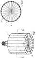
- reference numeral 1 denotes generally a rigid or semirigid blow molded bottle container according to the invention.
- the container comprises a cylindrical body provided with a flat bottom at one end, and provided at the other end with a screw threaded neck.
- the container shown is given only by way of illustrative example of a container which can be manufactured, and its shape, dimensions and proportions are not forming a part of the present invention, which is not in any way limited to cylindrical containers nor to containers provided with a screw threaded neck.
- the container of Figure 1 basically comprises two layers, namely one inner layer 2 and one outer layer 3, and a buried layer formed by a plurality of substantially parallel stripes 4 extending along the generating lines of the cylindrical body of the container 1, and converging toward the axis of the container in correspondence of the bottom and of the neck portion of the container, as best shown in Figure 1.
- the material of the buried striped layer 4 may be a recycled thermoplastic resin material.
- the head 5 has been shown and described as provided with three extrusion units 6, 7 and 8, it will be evident that same may be provided with a plurality and for instance with five of said units, so as to provide, in addition to the extruded layers described, an innermost layer formed for instance from a thermoplastic material exhibiting suitable barrier features, and with an outermost colored layer, so as to produce a five layer tube with embedded stripes.
Abstract
Method for the manufacture of a blow-molded reinforced thermoplastic material container (1) characterized by the steps of: extruding a continuous plastic tubular body made from at least a first comparatively weak thermoplastic material (2); coextruding into said tubular body a plurality of spaced parallel reinforcing stripes (4) made from a second comparatively strong thermoplastic material embedded within the body of said first thermoplastic material and extending axially along the lenght of said tubular body; feeding one lenght of said extruded reinforced striped continuous tubular body (28) to the mold of a blow-molding machine (29), and forming a blow molded reinforced striped container.
Description
- This invention relates generally to a method for the manufacture of blow-molded reinforced thermoplastic containers, and to the containers produced by said method.
- From US-A-3.394.433 a co-extrusion apparatus is known for forming a plastic tube of a first thermoplastic material with a ribbed mesh formed from a second thermoplastic material on the outer surface of the tube. The said outer ribbed mesh may be fiber reinforced and of different color.
- The presence of said external outwardly projecting reinforcing ribs is very objectionable should said tubes be subjected to a blow-molding process in order to produce bottle-like containers.
- From US-A-3.097.058 a process for extruding thermoplastic resins into tubes and blow molding said tubes into containers is known, according to which said tubes and by consequence the containers molded from said tubes are provided on their external surface with decorative stripes.
- From US-A-2.138.378 a process is known for the manufacture of rubber products in the form of continuous tubing and/or stripes, according to which stripes of coloured rubber material are placed upon the surface of a continuous tube or strip of rubber material extruded from a forming machine.
- None of the above prior art processes is concerned with the manufacture of blow-molded containers having embedded a reinforcing structure of a different thermoplastic material.
- It is therefore the main object of the invention to provide a method for the manufacture of plastic containers comprising a multi-stripe structure of thermoplastic or reinforcing material embedded within the thermoplastic body of these plastic containers so as to obtain an increased structural strength and resistance including but not limited to top load resistance, distention resistance and resistance to chocs.
- Furthermore, in order to contain the costs of manufacture of plastic material containers and in order to solve the ecological problem of the recycling of the waste of thermoplastic material, it has been suggested to produce said containers by a blow molding process, starting from a plastic material tube made from at least three co-extruded layers, namely an intermediate layer made from recycled material enclosed between an external layer and an internal layer made from virgin thermoplastic material. In order to assure that the the intermediate layer be bonded to the internal and external layers, it is necessary that the recycled material be exhibiting compatible chemical-physical characteristics of the virgin material of the surrounding layers of the containers.
- This method permits to obtain an economy of virgin material equivalent to the quantity of recycled material used which could be as high as 50 to 60%, depending on the shape and coànformation of the container, of the whole amount of thermoplastic material requested for the production of the containers. However, its use is confined to the use of a recycled thermoplastic material which is compatible with the thermoplastic material of the surrounding layers.
- The use of recycled material may bring as a result a diminution of mechanical/physical resistance characteristics of the plastic container for equal weight as virgin material.
- To reduce the cost of plastic containers and at the same time reduce the amount of packaging material introduced in the coaste stream it would be of considerable advantage to be able to reduce the total weight of plastic containers without loosing any of its physical barrier or resistance characteristics.
- It is therefore a further object of the invention to maintain the container strength and to safeguard the barrier properties of the container, with respect to a possible contamination of the product introduced in the container itself, whenever sub-quality regrind material (recycled thermoplastic material) is utilized in the structure.
- According to a main feature of the invention the above and other objects of the invention are obtained by a method for the manufacture of a blow-molded reinforced container characterized by the steps of: extruding a continuous plastic tubular body made from at least a first comparatively weak thermoplastic resin; coextruding into said tubular body a plurality of spaced parallel reinforcing stripes made from a second comparatively strong thermoplastic resin embedded within the body of said first thermoplastic resin and extending axially along the length of said tubular body; feeding one length of said extruded reinforced striped continuous tubular body to the mold of a blow-molding machine, and forming a blow molded reinforced striped container.
- According to a further feature of the invention, the said stripes may be made from a thermoplastic material which is not compatible with the body in which they are embedded and by which they are completely surrounded, so that said stripes are not joined or integrally bonded to the body which confines them in place.
- By this technique it is possible to form containers which by exhibiting the same strength or top load capability as the known prior art containers, present a weigth which is lower than the weigth of said prior art containers.
- It is also a further object of the invention to provide a blow-molded container comprising at least one body of a first comparatively weak thermoplastic resin embedding a plurality of spaced parallel stripes made from a second comparatively strong thermoplastic resin.
- According to a further aspect of the invention, the said body may be advantageously made from at least two layers of the same or of compatible thermoplastic resins, embedding the said spaced parallel stripes of, advantageously, a recycled thermoplastic resin material, which may be formed from a thermoplastic resin compatible or not compatible with the said surrounding thermoplastic resin layers in which said stripes are embedded.
- Further objects and advantages of the present invention will become apparent from the following description of some preferred embodiments, made with reference to the accompanying drawings, in which
- Figure 1 is a perspective view of a container according to the invention.
- Figure 2 is a cross sectional view of the container of Figure 1, taken along the plane of line II-II of Figure 1.
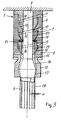
- Figure 3 is a diagrammatical longitudinal sectional view of a three layer extrusion head for the co-extrusion of a stripe reinforced thermoplastic tube for the manufacture of the blow molded containers according to the invention.
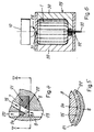
- Figure 4 is a detail in enlarged scale in longitudinal section of the stripe ring of the extrusion head of Figure 3.
- Figure 5 is a cross sectional view taken along the plane of line V-V of Figure 4, of the stripe ring of Figure 4, and
- Figure 6 is a diagrammatical, partially sectioned view of a blow-molding mold for the manufacture of the containers according to the invention.
- With reference to Figure 1, reference numeral 1 denotes generally a rigid or semirigid blow molded bottle container according to the invention. In the example shown, the container comprises a cylindrical body provided with a flat bottom at one end, and provided at the other end with a screw threaded neck. Of course, the container shown is given only by way of illustrative example of a container which can be manufactured, and its shape, dimensions and proportions are not forming a part of the present invention, which is not in any way limited to cylindrical containers nor to containers provided with a screw threaded neck.
- As best shown in Figure 2, the container of Figure 1 basically comprises two layers, namely one
inner layer 2 and oneouter layer 3, and a buried layer formed by a plurality of substantiallyparallel stripes 4 extending along the generating lines of the cylindrical body of the container 1, and converging toward the axis of the container in correspondence of the bottom and of the neck portion of the container, as best shown in Figure 1. - Although in Figure 2 the said stripes are shown as having a circular cross sectional shape, same may advantageously be formed with a non-circular cross sectional shape, and for example with a polygonal cross sectional shape (square, triangular, hexagonal or the like) or with an elliptical cross sectional shape, or with any other desired suitable cross sectional shape.
- Further, although the body of the container has been shown as formed from a three layer tube, comprising inner and
outer layers layer 4, it will be evident that it may be formed from a single material or a multi layer tube, and for instace a five layers tube, so as to comprise, for instance, in addition to the three layers shown in Figure 2, a fourth, external colored layer, and a fifth, internal, barrier layer made from a suitable thermoplastic resin having barrier properties, and for instance a layer of a thermoplastic resin suitable for edible products, or the like. - Moreover, although in Figure 2 the container is shown as formed by a three-layers tube, it will be evident that it is possible to make it from a two layers tube, by co-extruding the
stripes 4 inside of the mass of a tube being extruded. - Advantageously, the outer and inner layers are made from similar materials or the same material, i.e. a comparatively weaker thermoplastic resin with possible addition of color to the outer layer, while the buried
layer 4 is made from a stronger thermoplastic resin. - A good example would be a container made of high density copolimer polyethylene in which would be embedded reinforcing stripes of high molecular weight or semi high molecular weight polyethylene.
- Advantageously, the material of the buried striped
layer 4 may be a recycled thermoplastic resin material. - Thanks to the presence of the
stronger reinforcing stripes 4, the result will be an increased vertical load capability in the case of the virgin stripe materials and a maintained top load capability in the case of the use of recycled material for thestripes 4 of the container 1. - This means that, at parity of vertical load capability and/or top load capability, it is possible to decrease the total amount of material forming the container by a significant value.
- Since the reinforcing stripes are completely buried between the
layers - Of course the number and the reciprocal distance of the
stripes 4 shown in Figures 1 and 2 is given only for illustration purposes, and the said parameters may be varied at will, according to the requirements. - With reference to Figure 3, an extrusion head suitable for the production of a tube for the subsequent blow molding of the container of Figure 1 will be described.
- The
extrusion head 5 comprises, in the example shown, threeannular extrusion units cylindrical portion 9 of a central core member extending up to thedie head 10, as will be better described later. - Each
extrusion unit inlet spouts spouts manifold annulus tapered die annulus annular extrusion chamber 20, in which the outermost layer of the composite extrusion tubing is formed. - Die
annulus 18 communicates with thestripe ring 21. As best shown in Figures 4 and 5, thestripe ring 21 is provided with a crown of stripe-extrusion holes 22 communicating at one side withdie annulus 18, and at the other side with the secondannular extrusion chamber 23. The saidring 21 is further provided with ascalloped collar 24 protruding radially inwardly intoannular chamber 20 up to a certain distance from thecore 9, so as to provide a number offlow passages 25 surrounding the stripes-extrusion holes 22. - The
third die annulus 19, communicates in turn with thethird extrusion chamber 25. As it is apparent from Figure 3, the width of the annulargaps defining chambers chamber 20 tochamber 25, so as to accomodate the different layers forming the final multi layer tube.Chamber 25 communicates in turn with the diehead 10. The diehead 10 is provided with a first outwardly flaring, gradually restrictedannular passage 26, communicating in turn with the inwardly taperingannular die passage 27 from which the finishedthermoplastic tube 28 is extruded. The said tube, in the example shown, is composed by anouter layer 3, aninner layer 2, and a central layer formed by a plurality ofstripes 4. - Of course, although the
head 5 has been shown and described as provided with threeextrusion units - In Figure 6 a blow molding mold is shown, for blow molding into a suitable container 1 the
tube 28 extruded fromhead 5. - A conventional method of blow molding utilizes a
mold 29 comprising twoidentical halves 30 which pinch off thetube 28 at 31 and 32. The pinch-off at 31 is complete to seal the tube length at the bottom while that at 32 leaves a small orifice which permits injection throughinjection nozzle 33, connected to a suitable source (not shown) of compressed gas, of air or other blowing gas into the tube length to force the walls thereof quickly and uniformly outwardly against the die shape to form bottle 1, for example. - The operation of the described device will be evident.
- The molten thermoplastic resin from the extruders (not shown) is fed to the
inlet spouts extrusion head 5. The thermoplastic resin fed tospout 11 is transformed by die annulus 17 into a firsttubular layer 2 which is fed throughchamber 20, andpast extrusion ring 21. In correspondence ofring 21, thestripes 4 are extruded throughextrusion holes 22 and thetubular layer 3 with the crown ofstripes 4 applied against its surface is moved throughchamber 23 up todie annulus 19, in correspondence of which it is wrapped by the third, externaltubular layer 3. The composite three-layer tubular sandwich is thereafter passed through diehead 10, from which it is extruded in form of a continous three-layer tube 28. - Thereafter, as shown in Figure 6, one length of the
tube 28 is fed to the blow-molding die 29, in which it is shaped into the container 1. - Of course, the extrusion head described is given by way of non limiting example, and other extrusion apparatuses can be used to produce the multi-layer tube according to the invention, and for instance a device can be used like the one described in US-A-3.394.433, in order to have the stripes arranged according to an helical pattern inside of the composite tube.
Claims (15)
- Method for the manufacture of a blow-molded reinforced thermoplastic material container characterized by the steps of: extruding a continuous plastic tubular body made from at least a first comparatively weak thermoplastic material; coextruding into said tubular body a plurality of spaced parallel reinforcing stripes made from a second comparatively strong thermoplastic material embedded within the body of said first thermoplastic material and extending axially along the length of said tubular body; feeding one length of said extruded reinforced striped continuous tubular body to the mold of a blow-molding machine, and forming a blow molded reinforced striped container.
- Method according to claim 1, in which said stripes are formed from a recycled thermoplastic material.
- Method according to claims 1 and 2, in which the said stripes are made from a thermoplastic material which is not compatible with the thermoplastic material of the body in which they are embedded and by which they are completely surrounded, so that said stripes are not joined or integrally bonded to the thermoplastic material of the body which confines them in place.
- Method according to the preceding claims in which said body is formed by at least two concentric tubular layers of said first thermoplastic material, between which a layer of stripes of said second thermoplastic material is enclosed.
- Method according to the preceding claims, in which said stripes extend parallel to the generating lines of said tubular layers.
- Method according to claims 1 to 4, in which said stripes extend following a helical line pattern between said tubular layers.
- Method according to the preceding claims in which said stripes are made from a high density, high strength thermoplastic material.
- Method according to claim 7, in which said stripes are made from a recycled thermoplastic material.
- A blow molded container made according to the method of claims 1 to 8, characterized by the fact that it comprises at least one body of a first comparatively weak thermoplastic resin embedding a layer formed by a plurality of spaced parallel stripes made from a second comparatively strong thermoplastic resin.
- A blow-molded container according to claim 9 characterized by the fact that the said embedded layer of reinforcing stripes of strong thermoplastic material extends along the generating lines of the container.
- A container according to claim 9, characterized by the fact it is formed by at least one inner and one outer tubular layer made from compatible thermoplastic materials, and one intermediate striped layer of high strength thermoplastic material buried between said inner and outer layers.
- A container according to claims 9 to 11, in which said intermediante layer is formed from recycled thermoplastic material.
- A container according to claim 12, in which said recycled thermoplastic material is made from a thermoplastic resin which is not compatible with the surrounding thermoplastic resin layers.
- A device for the manufacture of a container according to claims 9 to 13 by the method according to claims 1 to 8, comprising a plurality of extruders; a coextrusion head provided with a plurality of annular extrusion chambers each connected to one of the said extruders; and a blow-forming mold disposed downstream of said coextrusion head.
- A device according to claim 14, in which at least one of the said extrusion chambers is provided with means for extruding a layer of stripes of thermoplastic material.
Priority Applications (1)
| Application Number | Priority Date | Filing Date | Title |
|---|---|---|---|
| EP92109667A EP0573683A1 (en) | 1992-06-09 | 1992-06-09 | Method for the manufacture of blow-molded reinforced thermoplastic containers, and containers produced by said method |
Applications Claiming Priority (1)
| Application Number | Priority Date | Filing Date | Title |
|---|---|---|---|
| EP92109667A EP0573683A1 (en) | 1992-06-09 | 1992-06-09 | Method for the manufacture of blow-molded reinforced thermoplastic containers, and containers produced by said method |
Publications (1)
| Publication Number | Publication Date |
|---|---|
| EP0573683A1 true EP0573683A1 (en) | 1993-12-15 |
Family
ID=8209690
Family Applications (1)
| Application Number | Title | Priority Date | Filing Date |
|---|---|---|---|
| EP92109667A Withdrawn EP0573683A1 (en) | 1992-06-09 | 1992-06-09 | Method for the manufacture of blow-molded reinforced thermoplastic containers, and containers produced by said method |
Country Status (1)
| Country | Link |
|---|---|
| EP (1) | EP0573683A1 (en) |
Cited By (9)
| Publication number | Priority date | Publication date | Assignee | Title |
|---|---|---|---|---|
| WO1995024302A1 (en) * | 1994-03-11 | 1995-09-14 | Olivier Simon Lefort | Tubular multilayer preform and method and device for the manufacture thereof |
| US6405887B1 (en) * | 1998-12-16 | 2002-06-18 | Graham Packaging Company, L.P. | Blow-molded container having reinforcement ribs and method and apparatus for making same |
| EP1271034A1 (en) * | 2001-06-28 | 2003-01-02 | ALBER KUNSTSTOFFTECHNIK GmbH | Coextruded plastic hose |
| US7063222B2 (en) * | 2000-12-05 | 2006-06-20 | Toyo Seikan Kaisha, Ltd. | Plastic container |
| US7090791B2 (en) * | 2001-04-20 | 2006-08-15 | Ispa, Inc | Extrusion molding process |
| WO2015108494A1 (en) * | 2014-01-20 | 2015-07-23 | Senapa-Stampa Ambalaj Sanayi̇ Ve Ti̇caret Anoni̇m Şi̇rketi̇ | Method for manufacturing a strength increasing column structure for plastic bottles |
| WO2015175208A1 (en) * | 2014-05-15 | 2015-11-19 | Dow Global Technologies Llc | System, method and apparatus for producing a multi-layer, annular microcapillary product |
| CN106467189A (en) * | 2015-08-21 | 2017-03-01 | 永裕塑胶工业股份有限公司 | Plastic bottle |
| CN114474675A (en) * | 2020-11-13 | 2022-05-13 | 盖普拉斯特股份有限公司 | Method for producing a container |
Citations (7)
| Publication number | Priority date | Publication date | Assignee | Title |
|---|---|---|---|---|
| US2138378A (en) * | 1934-02-21 | 1938-11-29 | Johnson John Herbert | Method and means of making striped rubber products |
| US3097058A (en) * | 1960-08-01 | 1963-07-09 | Phillips Petroleum Co | Extrusion of thermoplastic resins |
| GB1281682A (en) * | 1968-06-28 | 1972-07-12 | Creators Ltd | Improvements in or relating to flexible plastics hose |
| DE2236163A1 (en) * | 1972-07-24 | 1974-02-21 | Lissmann Alkor Werk | Partially-stretched film prodn - using strands in centre layer of higher m pt than outer layers |
| US3825036A (en) * | 1971-05-19 | 1974-07-23 | Creators Ltd | Reinforced plastics tubes |
| DE1753839A1 (en) * | 1966-02-08 | 1975-02-06 | Dow Chemical Co | METHOD FOR MANUFACTURING MULTI-LAYER PLASTIC SHEETS AND DEVICE FOR CARRYING OUT THE METHOD |
| DE3721438A1 (en) * | 1986-06-30 | 1988-01-21 | Toyoda Gosei Kk | MACHINE FOR PRODUCING A REINFORCED HOSE |
-
1992
- 1992-06-09 EP EP92109667A patent/EP0573683A1/en not_active Withdrawn
Patent Citations (7)
| Publication number | Priority date | Publication date | Assignee | Title |
|---|---|---|---|---|
| US2138378A (en) * | 1934-02-21 | 1938-11-29 | Johnson John Herbert | Method and means of making striped rubber products |
| US3097058A (en) * | 1960-08-01 | 1963-07-09 | Phillips Petroleum Co | Extrusion of thermoplastic resins |
| DE1753839A1 (en) * | 1966-02-08 | 1975-02-06 | Dow Chemical Co | METHOD FOR MANUFACTURING MULTI-LAYER PLASTIC SHEETS AND DEVICE FOR CARRYING OUT THE METHOD |
| GB1281682A (en) * | 1968-06-28 | 1972-07-12 | Creators Ltd | Improvements in or relating to flexible plastics hose |
| US3825036A (en) * | 1971-05-19 | 1974-07-23 | Creators Ltd | Reinforced plastics tubes |
| DE2236163A1 (en) * | 1972-07-24 | 1974-02-21 | Lissmann Alkor Werk | Partially-stretched film prodn - using strands in centre layer of higher m pt than outer layers |
| DE3721438A1 (en) * | 1986-06-30 | 1988-01-21 | Toyoda Gosei Kk | MACHINE FOR PRODUCING A REINFORCED HOSE |
Cited By (13)
| Publication number | Priority date | Publication date | Assignee | Title |
|---|---|---|---|---|
| WO1995024302A1 (en) * | 1994-03-11 | 1995-09-14 | Olivier Simon Lefort | Tubular multilayer preform and method and device for the manufacture thereof |
| US6405887B1 (en) * | 1998-12-16 | 2002-06-18 | Graham Packaging Company, L.P. | Blow-molded container having reinforcement ribs and method and apparatus for making same |
| US7063222B2 (en) * | 2000-12-05 | 2006-06-20 | Toyo Seikan Kaisha, Ltd. | Plastic container |
| US7090791B2 (en) * | 2001-04-20 | 2006-08-15 | Ispa, Inc | Extrusion molding process |
| EP1271034A1 (en) * | 2001-06-28 | 2003-01-02 | ALBER KUNSTSTOFFTECHNIK GmbH | Coextruded plastic hose |
| WO2015108494A1 (en) * | 2014-01-20 | 2015-07-23 | Senapa-Stampa Ambalaj Sanayi̇ Ve Ti̇caret Anoni̇m Şi̇rketi̇ | Method for manufacturing a strength increasing column structure for plastic bottles |
| WO2015175208A1 (en) * | 2014-05-15 | 2015-11-19 | Dow Global Technologies Llc | System, method and apparatus for producing a multi-layer, annular microcapillary product |
| US20170087759A1 (en) * | 2014-05-15 | 2017-03-30 | Dow Global Technologies Llc | System, Method and Apparatus For Producing a Multi-Layer, Annular Microcapillary Product |
| CN106687277A (en) * | 2014-05-15 | 2017-05-17 | 陶氏环球技术有限责任公司 | System, method and apparatus for producing a multi-layer, annular microcapillary product |
| JP2017515706A (en) * | 2014-05-15 | 2017-06-15 | ダウ グローバル テクノロジーズ エルエルシー | System, method and apparatus for producing multilayer annular microcapillary products |
| CN106467189A (en) * | 2015-08-21 | 2017-03-01 | 永裕塑胶工业股份有限公司 | Plastic bottle |
| CN114474675A (en) * | 2020-11-13 | 2022-05-13 | 盖普拉斯特股份有限公司 | Method for producing a container |
| CN114474675B (en) * | 2020-11-13 | 2024-03-08 | 盖普拉斯特股份有限公司 | Method for manufacturing container |
Similar Documents
| Publication | Publication Date | Title |
|---|---|---|
| US4522775A (en) | Apparatus and method for producing multilayered laminates | |
| US4824618A (en) | Coextrusion blowmolding process | |
| AU684372B2 (en) | Multi-layer containers | |
| KR101154849B1 (en) | Multilayer dose | |
| JP2007525347A5 (en) | ||
| JP2007525347A6 (en) | Multilayer dose | |
| EP0573683A1 (en) | Method for the manufacture of blow-molded reinforced thermoplastic containers, and containers produced by said method | |
| JPH0733027B2 (en) | Method for producing a tube with a multilayer tube head and a tube comprising a tube with at least one plastic layer and a multilayer tube head | |
| US6641881B1 (en) | Liner and preform | |
| US5779959A (en) | Process for forming plastic articles | |
| US20070273068A1 (en) | Blow molding extrusion apparatus and method | |
| US4521368A (en) | Method of making internally cross-ribbed plastics material structure | |
| US20140271962A1 (en) | Triple parison coextrusion multi-layer flowhead apparatus | |
| EP1676687A1 (en) | Multilayered molten resin mass, multilayered preform for blow molding formed from the multilayered molten resin mass by compression molding, and multilayered container | |
| EP0568544B1 (en) | Modular tubular extrusion head and a process for extruding tubular articles | |
| CA1270451A (en) | Apparatus and method for producing multi-layered laminates and improved multi-layered laminates produced therefrom | |
| JP3869864B2 (en) | Extrusion head for extruding multi-layer tubular items | |
| JP3869864B6 (en) | Extrusion head for extruding multi-layer tubular items | |
| MXPA06010027A (en) | Synthetic multilayer object | |
| CA2080143A1 (en) | Blow molding apparatus and method with parison uniformity and alignment control |
Legal Events
| Date | Code | Title | Description |
|---|---|---|---|
| PUAI | Public reference made under article 153(3) epc to a published international application that has entered the european phase |
Free format text: ORIGINAL CODE: 0009012 |
|
| AK | Designated contracting states |
Kind code of ref document: A1 Designated state(s): AT BE CH DE DK ES FR GB GR IT LI LU NL PT SE |
|
| STAA | Information on the status of an ep patent application or granted ep patent |
Free format text: STATUS: THE APPLICATION IS DEEMED TO BE WITHDRAWN |
|
| 18D | Application deemed to be withdrawn |
Effective date: 19940616 |