EP0578121A1 - Process for measuring and regulating the pressure of a tracheal cuff - Google Patents
Process for measuring and regulating the pressure of a tracheal cuff Download PDFInfo
- Publication number
- EP0578121A1 EP0578121A1 EP93110431A EP93110431A EP0578121A1 EP 0578121 A1 EP0578121 A1 EP 0578121A1 EP 93110431 A EP93110431 A EP 93110431A EP 93110431 A EP93110431 A EP 93110431A EP 0578121 A1 EP0578121 A1 EP 0578121A1
- Authority
- EP
- European Patent Office
- Prior art keywords
- pressure
- cuff
- sealing sleeve
- patient
- compressed air
- Prior art date
- Legal status (The legal status is an assumption and is not a legal conclusion. Google has not performed a legal analysis and makes no representation as to the accuracy of the status listed.)
- Granted
Links
Images


Classifications
-
- A—HUMAN NECESSITIES
- A61—MEDICAL OR VETERINARY SCIENCE; HYGIENE
- A61M—DEVICES FOR INTRODUCING MEDIA INTO, OR ONTO, THE BODY; DEVICES FOR TRANSDUCING BODY MEDIA OR FOR TAKING MEDIA FROM THE BODY; DEVICES FOR PRODUCING OR ENDING SLEEP OR STUPOR
- A61M16/00—Devices for influencing the respiratory system of patients by gas treatment, e.g. mouth-to-mouth respiration; Tracheal tubes
- A61M16/04—Tracheal tubes
- A61M16/0434—Cuffs
- A61M16/044—External cuff pressure control or supply, e.g. synchronisation with respiration
-
- A—HUMAN NECESSITIES
- A61—MEDICAL OR VETERINARY SCIENCE; HYGIENE
- A61M—DEVICES FOR INTRODUCING MEDIA INTO, OR ONTO, THE BODY; DEVICES FOR TRANSDUCING BODY MEDIA OR FOR TAKING MEDIA FROM THE BODY; DEVICES FOR PRODUCING OR ENDING SLEEP OR STUPOR
- A61M16/00—Devices for influencing the respiratory system of patients by gas treatment, e.g. mouth-to-mouth respiration; Tracheal tubes
- A61M16/021—Devices for influencing the respiratory system of patients by gas treatment, e.g. mouth-to-mouth respiration; Tracheal tubes operated by electrical means
Definitions
- the invention relates to a method according to the preamble of claim 1 and to an apparatus for performing the method.
- the cuff fulfills two essential tasks, on the one hand it enables gas-tight ventilation, and on the other hand it avoids the aspiration of liquid from the patient's oral cavity into his airways. In order to fulfill these tasks, a fixed cuff pressure of 20-20 mbar is usually chosen.
- FIG. 1 shows a cuff cuff arrangement described in DE-GBM 91 04 637 for sealing a cuff 12 of a tube 10 inserted into the trachea of a patient.
- the arrangement has a compressed air reservoir 14, a pressure line 16 leading from the compressed air reservoir 14 to the collar 12, an electrically controllable supply air valve 18, an electrically controllable exhaust air valve 20, and a pressure sensor measuring the pressure in the collar 12 22 and a control unit 24.
- the compressed air reservoir 14 is supplied with compressed air from a compressed air source via a reducing valve 26, the reducing valve being set to a value which is well above the normal pressure in the cuff sleeve but below the pressure which leads to the cuff sleeve tearing could.
- the control unit 24 measures the pressure in the cuff cuff 10 via the pressure sensor 22 and compares this actual pressure with a target pressure calculated by the control unit 24, the target pressure being the history of the pressure profile and the current profile of the pressure drop or should take into account the increase. If the pressure is too low, the device 24 controls the supply air valve 18, the pressure in the cuff cuff 10 is increased by the connection made to the compressed air reservoir 14. On the other hand, if the actual pressure exceeds the target pressure, the exhaust air valve 20 is activated, the cuff cuff 12 is connected to the outside air, and the pressure in the cuff cuff is reduced accordingly.
- the invention is based on the object of proposing a method for measuring and regulating the pressure in the sealing sleeve of a tracheal tube, by means of which a constant pressure of the sealing sleeve against the patient's trachea is achieved even with large and steep increases in pressure, for example caused by coughing from the patient's cough gas-tight ventilation and in order to prevent the aspiration of liquids from the patient's oral cavity into his respiratory tract.
- control device detects large and steep pressure increases which deviate from the nominal pressure in the sealing sleeve and as an expected widening of the trachea and consequently as a drop in the pressure in the sealing sleeve be evaluated that the control device increases the pressure prevailing in the sealing sleeve by adding air for a limited and defined period of time, and that the pressure present in the sealing sleeve is then controlled at a low control speed against the original nominal pressure.
- a device for carrying out the method according to the invention is claimed in claim 7, while subclaims 8 to 10 contain further developments of the device according to the invention.
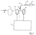
- the device shown in FIG. 2 differs from the known cuff sleeve arrangement according to FIG. 1 in particular by a simplified illustration of the device for generating pressure 1, by illustrated operating elements 2, by an autonomous processor monitoring unit 3 and by a seal sleeve 4 in the immediate vicinity of the tracheal tube 5 arranged pressure sensor 6.
- the pressure sensor 6 is arranged in a second compressed air line 7, which is connected to the sealing sleeve 4 in addition to the compressed air line 8 connecting the sealing sleeve 4 to the supply air or exhaust air valve 18 or 20.
- the cross sections of the compressed air lines 7 and 8 are chosen such that an optimal control behavior is achieved becomes.
- the pressure prevailing in the sealing sleeve 4 is increased in a predictive manner for a limited and defined period of time.
- the sealing sleeve pressure is then regulated at a low control speed against the original nominal pressure.
- sealing sleeve pressure exceeds or falls below programmable alarm thresholds, an alarm is triggered.
- Leakages and micro-leaks are recognized via the balancing of supplied and removed air and communicated via alarm signals.
- All control and alarm thresholds can be set via a user menu. This allows the device to be adapted to individual needs.
- two predefined programs can be called up, for standard use in adults (adult menu and in children (children's menu).
Abstract
Description
Die Erfindung bezieht sich auf ein Verfahren gemäß dem Oberbegriff von Anspruch 1 und auf eine Vorrichtung zur Durchführung des Verfahrens.The invention relates to a method according to the preamble of claim 1 and to an apparatus for performing the method.
Es ist bekannt, zur Beatmung von Intensivpatienten endotracheale Tuben mit einer in der Luftröhre (Trachea) aufblasbaren Manschette (Cuff) zu verwenden. Hierbei erfüllt die Manschette zwei wesentliche Aufgaben, zum einen ermöglicht sie eine gasdichte Beatmung, zum anderen vermeidet sie die Aspiration von Flüssigkeit aus der Mundhöhle des Patienten in seine Atemwege. Um diese Aufgaben zu erfüllen, wird üblicherweise ein fixer Manschettendruck von 20-20 mbar gewählt.It is known to use endotracheal tubes with an inflatable cuff in the trachea for ventilating intensive care patients. Here, the cuff fulfills two essential tasks, on the one hand it enables gas-tight ventilation, and on the other hand it avoids the aspiration of liquid from the patient's oral cavity into his airways. In order to fulfill these tasks, a fixed cuff pressure of 20-20 mbar is usually chosen.
In Fig. 1 ist eine in dem DE-GBM 91 04 637 beschriebene Cuff-Manschettenanordnung zum Abdichten einer Manschette 12 eines in die Luftröhre eines Patienten eingesetzten Tubus 10 dargestellt. Die Anordnung weist einen Druckluftspeicher 14, eine von dem Druckluftspeicher 14 zu der Manschette 12 führende Druckleitung 16, ein elektrisch ansteuerbares Zuluftventil 18, ein elektrisch ansteuerbares Abluftventil 20, einen den Druck in der Manschette 12 messenden Drucksensor 22 und eine Steuereinheit 24 auf. Der Druckluftspeicher 14 wird über ein Reduzierventil 26 von einer Druckluftquelle mit Druckluft gespeist, wobei das Reduzierventil auf einen Wert eingestellt ist, der deutlich obenhalb des Normaldrucks in der Cuff-Manschette, aber unterhalb des Druckes liegt, der zu einem Zerreißen der Cuff-Manschette führen könnte. Die Steuereinheit 24 mißt über den Drucksensor 22 den Druck in der Cuff-Manschette 10 und vergleicht diesen Ist-Druck mit einem von der Steuereinheit 24 errechneten Soll-Druck, wobei der Soll-Druck die Vorgeschichte des Druckverlaufs und den aktuellen Verlauf des Druckabfalls bzw. -anstiegs berücksichtigen sollte. Bei einem zu geringen Druck steuert die Einrichtung 24 das Zuluftventil 18 an, der Druck in der Cuff-Manschette 10 wird durch die hergestellte Verbindung mit dem Druckluftspeicher 14 erhöht. Überschreitet der Ist-Druck dagegen den Soll-Druck, wird das Abluftventil 20 angesteuert, die Cuff-Manschette 12 wird mit der Außenluft verbunden, der Druck in der Cuff-Manschette wird entsprechend gesenkt.1 shows a cuff cuff arrangement described in DE-GBM 91 04 637 for sealing a
Der Erfindung liegt die Aufgabe zugrunde, ein Verfahren zur Messung und Regelung des Druckes in der Dichtmanschette eines Trachealtubus vorzuschlagen, durch welches auch bei großen und steilen, beispielsweise durch Hustenstöße des Patienten hervorgerufenen Druckanstiegen ein konstanter Andruck der Dichtmanschette an die Luftröhre des Patienten zwecks Erzielung einer gasdichten Beatmung und zwecks Verhinderung der Aspiration von Flüssigkeiten aus der Mundhöhle des Patienten in seine Atemwege gewährleistet wird.The invention is based on the object of proposing a method for measuring and regulating the pressure in the sealing sleeve of a tracheal tube, by means of which a constant pressure of the sealing sleeve against the patient's trachea is achieved even with large and steep increases in pressure, for example caused by coughing from the patient's cough gas-tight ventilation and in order to prevent the aspiration of liquids from the patient's oral cavity into his respiratory tract.
Die Aufgabe wird erfindungsgemäß dadurch gelöst, daß von der Regeleinrichtung von dem Nominaldruck in der Dichtmanschette abweichende, große und steile Druckanstiege erkannt und als eine zu erwartende Weitstellung der Luftröhre und daraus resultierend als Abfall des Druckes in der Dichtmanschette gewertet werden, daß durch die Regeleinrichtung der in der Dichtmanschette herrschende Druck durch Luftzugabe für eine begrenzte und definierte Zeitdauer vorausschauend erhöht wird, und daß anschließend der in der Dichtmanschette vorhandene Druck mit kleiner Regelgeschwindigkeit gegen den ursprünglichen Nominaldruck geregelt wird.The object is achieved in that the control device detects large and steep pressure increases which deviate from the nominal pressure in the sealing sleeve and as an expected widening of the trachea and consequently as a drop in the pressure in the sealing sleeve be evaluated that the control device increases the pressure prevailing in the sealing sleeve by adding air for a limited and defined period of time, and that the pressure present in the sealing sleeve is then controlled at a low control speed against the original nominal pressure.
Ausgestaltungen des erfindungsgemäßen Verfahrens sind in den Unteransprüchen 2 bis 6 beschrieben.Embodiments of the method according to the invention are described in
Eine Vorrichtung zur Durchführung des erfindungsgemäßen Verfahrens ist im Anspruch 7 beansprucht, während die Unteransprüche 8 bis 10 Weiterbildungen der erfindungsgemäßen Vorrichtung enthalten.A device for carrying out the method according to the invention is claimed in claim 7, while subclaims 8 to 10 contain further developments of the device according to the invention.
In der Zeichnung ist ein Ausführungsbeispiel nach der Erfindung dargestellt, und zwar zeigt:
- Fig. 2
- eine erfindungsgemäße Vorrichtung in Blockschaltbildform, und
- Fig. 3
- eine graphische Darstellung der Drücke in der Dichtmanschette in Abhängigkeit von der Zeit.
- Fig. 2
- an inventive device in block diagram form, and
- Fig. 3
- a graphic representation of the pressures in the sealing sleeve as a function of time.
Die in Fig. 2 dargestellte diese Vorrichtung unterscheidet sich von der vorbekannten Cuff-Manschettenanordnung gemäß Fig. 1 insbesondere durch eine vereinfachte Darstellung der Einrichtung zur Druckerzeugung 1, durch dargestellte Bedienungselemente 2, durch eine autonome Prozessorüberwachungseinheit 3 und durch einen in unmittelbarer Nähe der Dichtungsmanschette 4 des Trachealtubus 5 angeordneten Drucksensor 6. Der Drucksensor 6 ist in einer zweiten Druckluftleitung 7 angeordnet, die neben der die Dichtmanschette 4 mit dem Zuluft- bzw. Abluftventil 18 bzw. 20 verbindende Druckluftleitung 8 an die Dichtmanschette 4 angeschlossen ist. Die Querschnitte der Druckluftleitungen 7 und 8 sind derart gewählt, daß ein optimales Regelverhalten erzielt wird. Andere Möglichkeiten bestehen beispielsweise darin, den Drucksensor in die Dichtmanschette zu integrieren bzw. in der Druckluftleitung 8 in unmittelbarer Nähe des Dichtmanschette anzuordnen. Durch die unmittelbare Nähe des Drucksensors 6 zur Dichtmanschette 4 wird vorteilhafterweise eine reale und schnelle Druckmessung erzielt.The device shown in FIG. 2 differs from the known cuff sleeve arrangement according to FIG. 1 in particular by a simplified illustration of the device for generating pressure 1, by illustrated
Unter Einbeziehung der graphischen Darstellung gemäß. Fig. 3 kann das erfindungsgemäße Verfahren zur Messung und Regelung des Druckes in der Dichtmanschette 4 eines Trachealtubus 5 wie folgt beschrieben werden.Including the graphical representation according to. 3, the method according to the invention for measuring and regulating the pressure in the sealing
Ein von dem Nominaldruck in der Dichtmanschette 4 abweichender großer und steiler Druckanstieg, der beispielsweise durch Hustenstöße hervorgerufen wird, wird von dem Drucksensor 6 gemessen und von der Regeleinrichtung als eine zu erwartende Weitstellung der Luftröhre und daraus resultierend als ein Abfall des Druckes in der Dichtmanschette 4 gewertet. Durch die Regeleinrichtung wird durch Luftzugabe der in der Dichtmanschette 4 herrschende Druck für eine begrenzte und definierte Zeitdauer vorausschauend erhöht. Anschließend wird der Dichtmanschettendruck mit kleiner Regelgeschwindigkeit gegen den ursprünglichen Nominaldruck geregelt.A large and steep pressure rise which deviates from the nominal pressure in the sealing
Wie die obigen Ausführungen zeigen, führt das Unterschreiten eines erwünschten Druckwertes in der Dichtmanschette 4, kurz Nominaldruck genannt, zum unmittelbaren und schnellen Eingreifen der Regeleinrichtung 6, 9. Liegt der Momentandruck (Istwert) innerhalb einer definierten Ruhezone, greift die Regeleinrichtung 6, 9 nicht ein (Totzone). Steigt der Druck über die obere Schwelle der Ruhezone, greift die Regeleinrichtung 6, 9 mit kleiner Regelgeschwindigkeit ausgleichend ein.As the above explanations show, falling below a desired pressure value in the
Über- oder unterschreitet der Dichtmanschetten-Druck programmierbare Alarmschwellen, so wird ein Alarm ausgelöst.If the sealing sleeve pressure exceeds or falls below programmable alarm thresholds, an alarm is triggered.
Über die Bilanzierung zugeführter und abgeführter Luft werden Leckagen und Mikroleckagen erkannt und über Alarmsignale mitgeteilt.Leakages and micro-leaks are recognized via the balancing of supplied and removed air and communicated via alarm signals.
Alle Regel- und Alarmschwellen sind über ein Benutzermenü einstellbar. Damit kann das Gerät den individuellen Bedürfnissen angepaßt werden. Neben dieser variablen Programmierung sind zwei vordefinierte Programmierungen abrufbar, und zwar für den Standardeinsatz bei Erwachsenen (Erwachsenenmenü und bei Kindern (Kindermenü).All control and alarm thresholds can be set via a user menu. This allows the device to be adapted to individual needs. In addition to this variable programming, two predefined programs can be called up, for standard use in adults (adult menu and in children (children's menu).
Claims (10)
Applications Claiming Priority (2)
| Application Number | Priority Date | Filing Date | Title |
|---|---|---|---|
| DE4222220A DE4222220A1 (en) | 1992-07-07 | 1992-07-07 | Procedure for measuring and regulating the pressure in the sealing sleeve of a tracheal tube |
| DE4222220 | 1992-07-07 |
Publications (2)
| Publication Number | Publication Date |
|---|---|
| EP0578121A1 true EP0578121A1 (en) | 1994-01-12 |
| EP0578121B1 EP0578121B1 (en) | 1997-04-09 |
Family
ID=6462628
Family Applications (1)
| Application Number | Title | Priority Date | Filing Date |
|---|---|---|---|
| EP93110431A Expired - Lifetime EP0578121B1 (en) | 1992-07-07 | 1993-06-30 | Process for measuring and regulating the pressure of a tracheal cuff |
Country Status (4)
| Country | Link |
|---|---|
| US (1) | US5361753A (en) |
| EP (1) | EP0578121B1 (en) |
| DE (2) | DE4222220A1 (en) |
| ES (1) | ES2100399T3 (en) |
Cited By (6)
| Publication number | Priority date | Publication date | Assignee | Title |
|---|---|---|---|---|
| EP0901395A1 (en) * | 1994-05-17 | 1999-03-17 | Hadasit Medical Research Services & Development Co. Ltd. | A system and method for cononary angioplasty |
| FR2774915A1 (en) * | 1998-02-13 | 1999-08-20 | Edouard Leveque | PRESSURE REGULATOR FOR INTUBATION PROBE, TRACHEOTOMY CANNULA OR SIMILAR INSTRUMENT |
| WO2009037447A2 (en) * | 2007-09-17 | 2009-03-26 | Indian Ocean Medical Inc. | Apparatus and method for monitoring an airway device such as an endotracheal tube |
| FR2940621A1 (en) * | 2008-12-29 | 2010-07-02 | Leved | Pressure regulator for e.g. intubation catheter in surgical field, has clamp comprising jaws applying constant and adjustable force on container for adjusting air pressure in variable volume chamber so as to adjust air pressure in cuff |
| WO2010077340A3 (en) * | 2008-12-31 | 2011-01-06 | Singh Manu B | Methods and apparatus for safe application of an intubation device |
| US10099027B2 (en) | 2014-01-24 | 2018-10-16 | Cole Research & Design | Oral suction device |
Families Citing this family (62)
| Publication number | Priority date | Publication date | Assignee | Title |
|---|---|---|---|---|
| US6758217B1 (en) * | 1993-02-05 | 2004-07-06 | University Of Manitoba | Control of airway pressure during mechanical ventilation |
| US5582167A (en) * | 1994-03-02 | 1996-12-10 | Thomas Jefferson University | Methods and apparatus for reducing tracheal infection using subglottic irrigation, drainage and servoregulation of endotracheal tube cuff pressure |
| US5503146A (en) * | 1994-10-26 | 1996-04-02 | Devilbiss Health Care, Inc. | Standby control for CPAP apparatus |
| US5878745A (en) | 1996-03-01 | 1999-03-09 | Brain; Archibald I.J. | Gastro-laryngeal mask |
| US5765559A (en) * | 1996-04-25 | 1998-06-16 | Higher Dimension Research, Inc. | Multi-cuffed endotracheal tube and method of its use |
| US7331346B2 (en) | 1997-12-24 | 2008-02-19 | Indian Ocean Medical, Inc. | Monitoring and control for a laryngeal mask airway device |
| GB9727367D0 (en) | 1997-12-24 | 1998-02-25 | Brain Archibald Ian Jeremy | Improvements in laryngeal mask airway devices |
| GB9821771D0 (en) | 1998-10-06 | 1998-12-02 | Brain Archibald Ian Jeremy | Improvements relating to laryngeal mask airway devices |
| US6287290B1 (en) * | 1999-07-02 | 2001-09-11 | Pulmonx | Methods, systems, and kits for lung volume reduction |
| EP1301232B1 (en) * | 2000-07-07 | 2018-06-13 | Indian Ocean Medical Inc. | Monitoring and control for a laryngeal mask airway device |
| US6527761B1 (en) | 2000-10-27 | 2003-03-04 | Pulmonx, Inc. | Methods and devices for obstructing and aspirating lung tissue segments |
| US20060135947A1 (en) | 2000-10-27 | 2006-06-22 | Pulmonx | Occlusal stent and methods for its use |
| US7883471B2 (en) | 2001-09-10 | 2011-02-08 | Pulmonx Corporation | Minimally invasive determination of collateral ventilation in lungs |
| EP1435833B1 (en) * | 2001-09-10 | 2014-05-21 | Pulmonx | Apparatus for endobronchial diagnosis |
| US20060162731A1 (en) | 2004-11-16 | 2006-07-27 | Pulmonx | Pulmonary occlusal stent delivery catheter, loading system and methods of use |
| US11883029B2 (en) | 2005-01-20 | 2024-01-30 | Pulmonx Corporation | Methods and devices for passive residual lung volume reduction and functional lung volume expansion |
| US8496006B2 (en) | 2005-01-20 | 2013-07-30 | Pulmonx Corporation | Methods and devices for passive residual lung volume reduction and functional lung volume expansion |
| US20080228137A1 (en) | 2007-03-12 | 2008-09-18 | Pulmonx | Methods and devices for passive residual lung volume reduction and functional lung volume expansion |
| US8876791B2 (en) | 2005-02-25 | 2014-11-04 | Pulmonx Corporation | Collateral pathway treatment using agent entrained by aspiration flow current |
| GB0510951D0 (en) | 2005-05-27 | 2005-07-06 | Laryngeal Mask Company The Ltd | Laryngeal mask airway device |
| US20070142742A1 (en) * | 2005-07-13 | 2007-06-21 | Pulmonx | Methods and systems for segmental lung diagnostics |
| CN102038992B (en) | 2005-08-24 | 2013-04-10 | 呼吸医疗技术有限公司 | Adjustment of endotracheal tube cuff filling |
| AU2006322905B2 (en) | 2005-12-05 | 2013-10-03 | Hospitech Respiration Ltd. | Endotracheal tube and intubation system including same |
| US8523782B2 (en) | 2005-12-07 | 2013-09-03 | Pulmonx Corporation | Minimally invasive determination of collateral ventilation in lungs |
| US8128574B2 (en) | 2006-09-25 | 2012-03-06 | Nellcor Puritan Bennett Llc | Carbon dioxide-sensing airway products and technique for using the same |
| US8307830B2 (en) | 2006-09-29 | 2012-11-13 | Nellcor Puritan Bennett Llc | Endotracheal cuff and technique for using the same |
| US20080221582A1 (en) * | 2007-03-05 | 2008-09-11 | Pulmonx | Pulmonary stent removal device |
| US8100959B2 (en) * | 2007-03-09 | 2012-01-24 | Pulmonx Corporation | Loading device for a pulmonary implant |
| AU2014262286B2 (en) * | 2007-09-17 | 2016-07-28 | Indian Ocean Medical Inc. | Apparatus and method for monitoring an airway device such as an endotracheal tube |
| US20100036361A1 (en) * | 2008-06-20 | 2010-02-11 | Pulmonx | System and method for delivering multiple implants into lung passageways |
| US8905029B2 (en) * | 2008-09-29 | 2014-12-09 | Covidien Lp | Airway system with carbon dioxide sensor for determining tracheal cuff inflation and technique for using the same |
| GB0903654D0 (en) | 2009-03-03 | 2009-04-15 | Laryngeal Mask Company The Ltd | Artificial airway device |
| US8603003B2 (en) * | 2009-06-03 | 2013-12-10 | Covidien Lp | Trachea pressure determination method and device |
| US8473033B2 (en) * | 2009-06-17 | 2013-06-25 | Covidien Lp | Method and system for determining tracheal and location information for a tracheal tube |
| US8596277B2 (en) * | 2009-06-18 | 2013-12-03 | Covidien Lp | Tracheal tube with lumen for tracheal pressure measurement and technique for using the same |
| US8844534B2 (en) * | 2009-06-30 | 2014-09-30 | Covidien Lp | Tracheal tube with lumen for tracheal pressure measurement and technique for using the same |
| KR20120070559A (en) | 2009-07-06 | 2012-06-29 | 우메데이스 리미티드 | Artificial airway |
| CN102498377B (en) | 2009-08-13 | 2014-05-14 | 奇姆德恩医疗有限公司 | Pressure indicator |
| US20110144514A1 (en) * | 2009-12-16 | 2011-06-16 | Nellcor Puritan Bennett Llc | Tracheal Tube with Pressure Monitoring Lumen and Method for Using the Same |
| US9339208B2 (en) * | 2010-01-18 | 2016-05-17 | Covidien Lp | Tracheal tube with pressure monitoring lumen and method for using the same |
| US20110213264A1 (en) * | 2010-02-26 | 2011-09-01 | Nellcor Puritan Bennett Llc | Sensor on non-sealing portion of tracheal tube cuff |
| WO2011139499A1 (en) * | 2010-05-03 | 2011-11-10 | Convatec Technologies Inc. | Indwelling drainage appliance for body waste |
| GB201016562D0 (en) | 2010-10-01 | 2010-11-17 | Laryngeal Mask Company The Ltd | Artificial airway device |
| AU2011315319B2 (en) | 2010-10-15 | 2016-06-02 | Teleflex Life Sciences Llc | Artificial airway device |
| CN109200416A (en) | 2011-02-02 | 2019-01-15 | 梅田有限公司 | improved artificial airway |
| AU2012235744A1 (en) | 2011-03-29 | 2013-11-14 | Airway Medix S.A. | Ballooned ventilation tube cleaning device |
| GB201119794D0 (en) | 2011-11-16 | 2011-12-28 | Airway Medix Spolka Z O O | Ballooned ventilation tube cleaning device |
| US10058278B2 (en) * | 2011-10-13 | 2018-08-28 | Anaesthesia Associates Of Massachusetts, P.C. | Systems and methods for monitoring pressure applied on patients |
| GB201120628D0 (en) | 2011-11-30 | 2012-01-11 | Laryngeal Mask Company The Ltd | Endoscopy device |
| EP2800599B1 (en) * | 2012-01-03 | 2017-05-31 | Hospitech Respiration Ltd. | System for controlling and monitoring flow in an endotracheal tube |
| US9180268B2 (en) | 2012-05-01 | 2015-11-10 | Covidien Lp | Cuff pressure measurement device for a tracheal tube |
| US9433737B2 (en) * | 2013-03-15 | 2016-09-06 | Covidien Lp | Cuff pressure measurement device for a tracheal tube |
| US20150314092A1 (en) * | 2014-04-30 | 2015-11-05 | Covidien Lp | Tracheal tube with controlled-pressure cuff |
| US10500360B1 (en) | 2014-08-29 | 2019-12-10 | Teleflex Life Sciences Unlimited Company | Catheter for cleaning of tracheal ventilation tubes |
| US11452831B2 (en) | 2016-01-06 | 2022-09-27 | Airway Medix S.A. | Closed suction system |
| GB2546082B (en) | 2016-01-06 | 2018-05-16 | Airway Medix S A | Closed suction system |
| US10946153B2 (en) | 2016-05-16 | 2021-03-16 | Teleflex Life Sciences Pte. Ltd. | Mechanical user control elements for fluid input module |
| DE102016007336B4 (en) * | 2016-06-16 | 2023-08-10 | Drägerwerk AG & Co. KGaA | Medical device and method for organizing alarms |
| US10179219B2 (en) | 2017-04-13 | 2019-01-15 | Daniel Marcos Chapiro | Intubation device with variable backflow pressure |
| US10092719B1 (en) | 2017-09-13 | 2018-10-09 | Airway Medix S.A. | Catheter inflatable cuff pressure stabilizer |
| US10286170B1 (en) | 2018-02-20 | 2019-05-14 | Airway Medix S.A. | Catheter inflatable cuff pressure stabilizer |
| USD910853S1 (en) | 2019-05-29 | 2021-02-16 | Covidien Lp | Cuff pressure regulator |
Citations (4)
| Publication number | Priority date | Publication date | Assignee | Title |
|---|---|---|---|---|
| EP0362824A1 (en) * | 1988-10-04 | 1990-04-11 | pvb medizintechnik gmbh | Catheter for pressure measurement |
| EP0366524A1 (en) * | 1988-10-26 | 1990-05-02 | Georges Boussignac | Respiratory assistance apparatus |
| US5004472A (en) * | 1988-08-10 | 1991-04-02 | Wallace William D | Medical pressure sensing and display system |
| DE9104637U1 (en) * | 1991-04-16 | 1991-06-06 | Pothmann, Werner, Dr., 2000 Hamburg, De |
Family Cites Families (14)
| Publication number | Priority date | Publication date | Assignee | Title |
|---|---|---|---|---|
| US4046139A (en) * | 1976-08-23 | 1977-09-06 | Bernard Horn | Medical temperature measuring device |
| US4178940A (en) * | 1977-06-24 | 1979-12-18 | Au Anthony S | Pressure control systems |
| US4182344A (en) * | 1977-08-19 | 1980-01-08 | G. D. Searle & Co., Limited | Pressure control tracheal device |
| JPS5921495B2 (en) * | 1977-12-15 | 1984-05-21 | 株式会社豊田中央研究所 | Capillary pressure gauge |
| US4278081A (en) * | 1978-02-21 | 1981-07-14 | Jones James W | Tracheal tube |
| US4285340A (en) * | 1979-03-16 | 1981-08-25 | Gezari Walter A | Apparatus for controlling the pressure in a tracheal cuff |
| US4501273A (en) * | 1982-09-30 | 1985-02-26 | Mcginnis Gerald E | Endotracheal tube with pressure controlled inflatable cuff |
| US4502482A (en) * | 1983-05-23 | 1985-03-05 | Deluccia Victor C | Endotracheal tube complex |
| DE3327342A1 (en) * | 1983-07-29 | 1985-02-07 | Peter 7800 Freiburg Pedersen | DEVICE FOR DETECTING AND EVALUATING THE PRESSURE IN THE BALLOON CUFF OF A CLOSED TRACHEAL TUBE |
| JPS62186872A (en) * | 1986-02-14 | 1987-08-15 | 鳥取大学長 | Respiration pressure superposing type cuff pressure adjusting apparatus |
| US4813431A (en) * | 1987-07-22 | 1989-03-21 | David Brown | Intrapulmonary pressure monitoring system |
| DE3930964A1 (en) * | 1989-09-15 | 1991-03-28 | Thomson Brandt Gmbh | TELEVISION TRANSMISSION SYSTEM |
| IT1241932B (en) * | 1990-04-24 | 1994-02-01 | Manfred Pfaender | DEVICE FOR MEASURING AND CHECKING THE PRESSURE INSIDE THE HEADSET OF PIPES FROM GENERAL ANESTHESIA WITH ENDOTRACHEAL INTUBATION AND MECHANICAL VENTILATION |
| GB9026403D0 (en) * | 1990-12-05 | 1991-01-23 | Smiths Industries Plc | Pressure monitors |
-
1992
- 1992-07-07 DE DE4222220A patent/DE4222220A1/en not_active Ceased
-
1993
- 1993-06-30 ES ES93110431T patent/ES2100399T3/en not_active Expired - Lifetime
- 1993-06-30 EP EP93110431A patent/EP0578121B1/en not_active Expired - Lifetime
- 1993-06-30 DE DE59306088T patent/DE59306088D1/en not_active Expired - Fee Related
- 1993-07-07 US US08/086,889 patent/US5361753A/en not_active Expired - Fee Related
Patent Citations (5)
| Publication number | Priority date | Publication date | Assignee | Title |
|---|---|---|---|---|
| US5004472A (en) * | 1988-08-10 | 1991-04-02 | Wallace William D | Medical pressure sensing and display system |
| US5004472B1 (en) * | 1988-08-10 | 1995-02-28 | Utah Medical Products Inc | Medical pressure sensing and display system |
| EP0362824A1 (en) * | 1988-10-04 | 1990-04-11 | pvb medizintechnik gmbh | Catheter for pressure measurement |
| EP0366524A1 (en) * | 1988-10-26 | 1990-05-02 | Georges Boussignac | Respiratory assistance apparatus |
| DE9104637U1 (en) * | 1991-04-16 | 1991-06-06 | Pothmann, Werner, Dr., 2000 Hamburg, De |
Cited By (15)
| Publication number | Priority date | Publication date | Assignee | Title |
|---|---|---|---|---|
| EP0901395A1 (en) * | 1994-05-17 | 1999-03-17 | Hadasit Medical Research Services & Development Co. Ltd. | A system and method for cononary angioplasty |
| EP0901395A4 (en) * | 1994-05-17 | 1999-03-17 | ||
| FR2774915A1 (en) * | 1998-02-13 | 1999-08-20 | Edouard Leveque | PRESSURE REGULATOR FOR INTUBATION PROBE, TRACHEOTOMY CANNULA OR SIMILAR INSTRUMENT |
| CN101883603A (en) * | 2007-09-17 | 2010-11-10 | 印度洋医药公司 | Method for monitoring an airway device such as an endotrachael tube |
| WO2009037447A3 (en) * | 2007-09-17 | 2009-09-24 | Indian Ocean Medical Inc. | Apparatus and method for monitoring an airway device such as an endotracheal tube |
| WO2009037447A2 (en) * | 2007-09-17 | 2009-03-26 | Indian Ocean Medical Inc. | Apparatus and method for monitoring an airway device such as an endotracheal tube |
| RU2490033C2 (en) * | 2007-09-17 | 2013-08-20 | Индиан Оушн Медикал Инк. | Device and method for controlling air duct, such as endotracheal tube |
| CN101883603B (en) * | 2007-09-17 | 2015-11-25 | 印度洋医药公司 | For monitoring the equipment of the airway device of such as endotracheal tube |
| US9233219B2 (en) | 2007-09-17 | 2016-01-12 | Indian Ocean Medical Inc. | Apparatus and method for monitoring an airway device such as an endotracheal tube |
| US9358354B2 (en) | 2007-09-17 | 2016-06-07 | Indian Ocean Medical, Inc. | Apparatus and method for monitoring an airway device such as an endotracheal tube |
| US10137263B2 (en) | 2007-09-17 | 2018-11-27 | Indian Ocean Medical Inc. | Apparatus and method for monitoring an airway device such as an endotracheal tube |
| FR2940621A1 (en) * | 2008-12-29 | 2010-07-02 | Leved | Pressure regulator for e.g. intubation catheter in surgical field, has clamp comprising jaws applying constant and adjustable force on container for adjusting air pressure in variable volume chamber so as to adjust air pressure in cuff |
| WO2010077340A3 (en) * | 2008-12-31 | 2011-01-06 | Singh Manu B | Methods and apparatus for safe application of an intubation device |
| US8448636B2 (en) | 2008-12-31 | 2013-05-28 | Manu B. Singh | Methods and apparatus for safe application of an intubation device |
| US10099027B2 (en) | 2014-01-24 | 2018-10-16 | Cole Research & Design | Oral suction device |
Also Published As
| Publication number | Publication date |
|---|---|
| US5361753A (en) | 1994-11-08 |
| ES2100399T3 (en) | 1997-06-16 |
| DE4222220A1 (en) | 1994-01-13 |
| EP0578121B1 (en) | 1997-04-09 |
| DE59306088D1 (en) | 1997-05-15 |
Similar Documents
| Publication | Publication Date | Title |
|---|---|---|
| EP0578121B1 (en) | Process for measuring and regulating the pressure of a tracheal cuff | |
| DE102004006396B4 (en) | Device for ventilation and method for controlling a ventilator | |
| EP0169972B1 (en) | Device for insufflating gas into the body | |
| DE19606470C2 (en) | Procedure for determining the functional residual capacity (FRC) | |
| DE60128770T2 (en) | Respirator with adaptive trigger | |
| DE69922908T2 (en) | DOSING DEVICE FOR MEDICAL PURPOSES WITH PRESSURE SENSOR CONTAINING DOSING CHAMBER | |
| DE10014427A1 (en) | Method for controlling a ventilator and device for monitoring | |
| DE10217762C1 (en) | Respiration gas supply control method for artificial respirator compares actual respiration path pressure with intial respiration path pressure for regulation of respiration gas supply parameter | |
| DE3537507C2 (en) | Device for supportive intermittent pressure ventilation and aerosol therapy | |
| DE102004039711B3 (en) | Method for automatic recording of pressure-volume curves in artificial respiration and apparatus for carrying out the method | |
| EP0491969B1 (en) | Lung ventilator with a flow rate dependent trigger threshold | |
| DE69736808T2 (en) | DETERMINATION OF LEAKAGE FLOW | |
| DE19516536C2 (en) | Ventilator | |
| DE102007006689A1 (en) | Apparatus and method for detecting obstruction during apnea phases by an additional pressure stage | |
| DE3206482C2 (en) | Ventilation device with a device for safety monitoring | |
| EP0149009B1 (en) | Device for supplying respiratory gas to the closed respiratory circuit of a medical respiratory apparatus | |
| EP1306099A2 (en) | A method for controlling a ventilator and a ventilator | |
| DE3123678A1 (en) | METHOD AND DEVICE FOR CONTROLLING LUNG FANS | |
| DE2432932A1 (en) | METHOD AND DEVICE FOR TRIGGERING THE INHALATION PHASE IN A VENTILATION DEVICE | |
| CH701124B1 (en) | Respirator and adjustment method for this. | |
| DE102016012824A1 (en) | Method and apparatus for adaptively controlling positive end-expiratory pressure (PEEP) | |
| DE19717106A1 (en) | Device and method for automated ventilation in CPAP therapy | |
| EP3819002B1 (en) | Ventilator including a control unit for controlling oxygen concentration in a breathing gas | |
| DE2507981A1 (en) | DEVICE FOR THE CONTROL OF BREATHING IN VENTILATION DEVICES | |
| EP1346743A1 (en) | Method of controlling an artificial ventilator and ventilator therefor |
Legal Events
| Date | Code | Title | Description |
|---|---|---|---|
| PUAI | Public reference made under article 153(3) epc to a published international application that has entered the european phase |
Free format text: ORIGINAL CODE: 0009012 |
|
| AK | Designated contracting states |
Kind code of ref document: A1 Designated state(s): DE ES FR GB IT NL SE |
|
| 17P | Request for examination filed |
Effective date: 19940704 |
|
| RAP1 | Party data changed (applicant data changed or rights of an application transferred) |
Owner name: DAIMLER-BENZ AEROSPACE AKTIENGESELLSCHAFT |
|
| RAP1 | Party data changed (applicant data changed or rights of an application transferred) |
Owner name: ESW-EXTEL SYSTEMS WEDEL GESELLSCHAFT FUER AUSRUEST |
|
| 17Q | First examination report despatched |
Effective date: 19960206 |
|
| GRAG | Despatch of communication of intention to grant |
Free format text: ORIGINAL CODE: EPIDOS AGRA |
|
| GRAH | Despatch of communication of intention to grant a patent |
Free format text: ORIGINAL CODE: EPIDOS IGRA |
|
| GRAH | Despatch of communication of intention to grant a patent |
Free format text: ORIGINAL CODE: EPIDOS IGRA |
|
| GRAA | (expected) grant |
Free format text: ORIGINAL CODE: 0009210 |
|
| AK | Designated contracting states |
Kind code of ref document: B1 Designated state(s): DE ES FR GB IT NL SE |
|
| REF | Corresponds to: |
Ref document number: 59306088 Country of ref document: DE Date of ref document: 19970515 |
|
| REG | Reference to a national code |
Ref country code: ES Ref legal event code: FG2A Ref document number: 2100399 Country of ref document: ES Kind code of ref document: T3 |
|
| ET | Fr: translation filed | ||
| GBT | Gb: translation of ep patent filed (gb section 77(6)(a)/1977) |
Effective date: 19970711 |
|
| PLBE | No opposition filed within time limit |
Free format text: ORIGINAL CODE: 0009261 |
|
| STAA | Information on the status of an ep patent application or granted ep patent |
Free format text: STATUS: NO OPPOSITION FILED WITHIN TIME LIMIT |
|
| 26N | No opposition filed | ||
| PGFP | Annual fee paid to national office [announced via postgrant information from national office to epo] |
Ref country code: SE Payment date: 20010615 Year of fee payment: 9 |
|
| PGFP | Annual fee paid to national office [announced via postgrant information from national office to epo] |
Ref country code: ES Payment date: 20010620 Year of fee payment: 9 |
|
| PGFP | Annual fee paid to national office [announced via postgrant information from national office to epo] |
Ref country code: FR Payment date: 20010622 Year of fee payment: 9 Ref country code: DE Payment date: 20010622 Year of fee payment: 9 |
|
| PGFP | Annual fee paid to national office [announced via postgrant information from national office to epo] |
Ref country code: GB Payment date: 20010629 Year of fee payment: 9 |
|
| PGFP | Annual fee paid to national office [announced via postgrant information from national office to epo] |
Ref country code: NL Payment date: 20010630 Year of fee payment: 9 |
|
| REG | Reference to a national code |
Ref country code: GB Ref legal event code: IF02 |
|
| PG25 | Lapsed in a contracting state [announced via postgrant information from national office to epo] |
Ref country code: GB Free format text: LAPSE BECAUSE OF NON-PAYMENT OF DUE FEES Effective date: 20020630 |
|
| PG25 | Lapsed in a contracting state [announced via postgrant information from national office to epo] |
Ref country code: SE Free format text: LAPSE BECAUSE OF NON-PAYMENT OF DUE FEES Effective date: 20020701 Ref country code: ES Free format text: LAPSE BECAUSE OF NON-PAYMENT OF DUE FEES Effective date: 20020701 |
|
| PG25 | Lapsed in a contracting state [announced via postgrant information from national office to epo] |
Ref country code: NL Free format text: LAPSE BECAUSE OF NON-PAYMENT OF DUE FEES Effective date: 20030101 Ref country code: DE Free format text: LAPSE BECAUSE OF NON-PAYMENT OF DUE FEES Effective date: 20030101 |
|
| GBPC | Gb: european patent ceased through non-payment of renewal fee |
Effective date: 20020630 |
|
| PG25 | Lapsed in a contracting state [announced via postgrant information from national office to epo] |
Ref country code: FR Free format text: LAPSE BECAUSE OF NON-PAYMENT OF DUE FEES Effective date: 20030228 |
|
| NLV4 | Nl: lapsed or anulled due to non-payment of the annual fee |
Effective date: 20030101 |
|
| EUG | Se: european patent has lapsed | ||
| REG | Reference to a national code |
Ref country code: FR Ref legal event code: ST |
|
| REG | Reference to a national code |
Ref country code: ES Ref legal event code: FD2A Effective date: 20030711 |
|
| PG25 | Lapsed in a contracting state [announced via postgrant information from national office to epo] |
Ref country code: IT Free format text: LAPSE BECAUSE OF NON-PAYMENT OF DUE FEES;WARNING: LAPSES OF ITALIAN PATENTS WITH EFFECTIVE DATE BEFORE 2007 MAY HAVE OCCURRED AT ANY TIME BEFORE 2007. THE CORRECT EFFECTIVE DATE MAY BE DIFFERENT FROM THE ONE RECORDED. Effective date: 20050630 |