EP0594358A2 - Method and apparatus for reducing the peak-to-average power in multi-carrier RF communication systems - Google Patents
Method and apparatus for reducing the peak-to-average power in multi-carrier RF communication systems Download PDFInfo
- Publication number
- EP0594358A2 EP0594358A2 EP93308178A EP93308178A EP0594358A2 EP 0594358 A2 EP0594358 A2 EP 0594358A2 EP 93308178 A EP93308178 A EP 93308178A EP 93308178 A EP93308178 A EP 93308178A EP 0594358 A2 EP0594358 A2 EP 0594358A2
- Authority
- EP
- European Patent Office
- Prior art keywords
- power
- peak
- signal
- radio
- parallel channels
- Prior art date
- Legal status (The legal status is an assumption and is not a legal conclusion. Google has not performed a legal analysis and makes no representation as to the accuracy of the status listed.)
- Granted
Links
- 238000000034 method Methods 0.000 title claims description 12
- 238000004891 communication Methods 0.000 title claims description 4
- 230000004044 response Effects 0.000 claims abstract description 5
- 238000012545 processing Methods 0.000 claims abstract description 4
- 239000002131 composite material Substances 0.000 claims description 8
- 230000005540 biological transmission Effects 0.000 claims description 5
- 230000004075 alteration Effects 0.000 claims description 2
- 238000012544 monitoring process Methods 0.000 claims 5
- 230000009467 reduction Effects 0.000 abstract description 2
- 230000010363 phase shift Effects 0.000 description 10
- 239000000969 carrier Substances 0.000 description 3
- 230000008569 process Effects 0.000 description 3
- 230000003321 amplification Effects 0.000 description 2
- 230000001413 cellular effect Effects 0.000 description 2
- 230000008859 change Effects 0.000 description 2
- 230000006872 improvement Effects 0.000 description 2
- 238000005259 measurement Methods 0.000 description 2
- 238000003199 nucleic acid amplification method Methods 0.000 description 2
- 230000001360 synchronised effect Effects 0.000 description 2
- 238000003491 array Methods 0.000 description 1
- 239000003990 capacitor Substances 0.000 description 1
- 230000001276 controlling effect Effects 0.000 description 1
- 230000008878 coupling Effects 0.000 description 1
- 238000010168 coupling process Methods 0.000 description 1
- 238000005859 coupling reaction Methods 0.000 description 1
- 238000010586 diagram Methods 0.000 description 1
- 230000000694 effects Effects 0.000 description 1
- 238000011156 evaluation Methods 0.000 description 1
- 230000006870 function Effects 0.000 description 1
- 230000005055 memory storage Effects 0.000 description 1
- 238000005457 optimization Methods 0.000 description 1
- 230000000737 periodic effect Effects 0.000 description 1
- 230000001105 regulatory effect Effects 0.000 description 1
Images


Classifications
-
- H—ELECTRICITY
- H03—ELECTRONIC CIRCUITRY
- H03G—CONTROL OF AMPLIFICATION
- H03G3/00—Gain control in amplifiers or frequency changers without distortion of the input signal
- H03G3/20—Automatic control
- H03G3/30—Automatic control in amplifiers having semiconductor devices
- H03G3/3036—Automatic control in amplifiers having semiconductor devices in high-frequency amplifiers or in frequency-changers
- H03G3/3042—Automatic control in amplifiers having semiconductor devices in high-frequency amplifiers or in frequency-changers in modulators, frequency-changers, transmitters or power amplifiers
-
- H—ELECTRICITY
- H03—ELECTRONIC CIRCUITRY
- H03F—AMPLIFIERS
- H03F1/00—Details of amplifiers with only discharge tubes, only semiconductor devices or only unspecified devices as amplifying elements
- H03F1/34—Negative-feedback-circuit arrangements with or without positive feedback
-
- H—ELECTRICITY
- H04—ELECTRIC COMMUNICATION TECHNIQUE
- H04L—TRANSMISSION OF DIGITAL INFORMATION, e.g. TELEGRAPHIC COMMUNICATION
- H04L27/00—Modulated-carrier systems
- H04L27/26—Systems using multi-frequency codes
- H04L27/2601—Multicarrier modulation systems
- H04L27/2614—Peak power aspects
- H04L27/2621—Reduction thereof using phase offsets between subcarriers
-
- H—ELECTRICITY
- H04—ELECTRIC COMMUNICATION TECHNIQUE
- H04L—TRANSMISSION OF DIGITAL INFORMATION, e.g. TELEGRAPHIC COMMUNICATION
- H04L27/00—Modulated-carrier systems
- H04L27/26—Systems using multi-frequency codes
- H04L27/2601—Multicarrier modulation systems
- H04L27/2626—Arrangements specific to the transmitter only
- H04L27/2627—Modulators
- H04L27/2637—Modulators with direct modulation of individual subcarriers
-
- Y—GENERAL TAGGING OF NEW TECHNOLOGICAL DEVELOPMENTS; GENERAL TAGGING OF CROSS-SECTIONAL TECHNOLOGIES SPANNING OVER SEVERAL SECTIONS OF THE IPC; TECHNICAL SUBJECTS COVERED BY FORMER USPC CROSS-REFERENCE ART COLLECTIONS [XRACs] AND DIGESTS
- Y02—TECHNOLOGIES OR APPLICATIONS FOR MITIGATION OR ADAPTATION AGAINST CLIMATE CHANGE
- Y02D—CLIMATE CHANGE MITIGATION TECHNOLOGIES IN INFORMATION AND COMMUNICATION TECHNOLOGIES [ICT], I.E. INFORMATION AND COMMUNICATION TECHNOLOGIES AIMING AT THE REDUCTION OF THEIR OWN ENERGY USE
- Y02D30/00—Reducing energy consumption in communication networks
- Y02D30/70—Reducing energy consumption in communication networks in wireless communication networks
Definitions
- This invention relates to multi-channel signal amplification systems in a communication system and to a method and apparatus for increasing the average power handling capacity of such a multi-channel signal amplifier relative to its peak power rating. It is also concerned with preventing variations of the phases of individual carrier signals comprising the multiple channel signal from causing occurrences of very high envelope signal peaks in the multichannel signal.
- the power signals of many channels are combined into a composite signal.
- This composite signal is split into many parallel paths and coupled to individual radio transmitters in each parallel path.
- the output radio transmission signals of the plurality of radio transmitters are combined and amplified in a single poweram- plifier. Individual signal peaks in each of the parallel paths may coincide and cause a composite peak power to occur at the single power amplifier that greatly exceeds its power handling capacity.
- the various radio channels are distributed in frequency with respect to each other in that each operates within a different frequency band.
- Each channel is FM modulated and hence has a signal of substantially constant amplitude.
- the peak occurrences of the combined signal is a highly complicated function of the individual carrier frequencies, modulation methods, signal contents and noise. Since the simultaneous occurrence of individual signal peaks can not easily be avoided, a multi-channel signal is subject to power maximums where the peak power significantly exceeds the average power of the envelope due to constructive addition of the individual signals.
- U.S. patent 4,064,464 discloses an amplifier system, including a powerspiitterfordividing an input signal into a plurality of channels and feeding each channel into a plurality of power amplifiers connected in parallel. The several output of the parallel connected power amplifiers are combined into a single output by a subsequent power combiner connected to the paralleled outputs of the power amplifiers.
- the input to one of the paralleled amplifiers includes a voltage controlled phase shifter that is responsive to a deviation of the power output of the power combiner from a reference value. This feedback arrangement maintains the power output at a regulated value.
- This is however, an amplification technique having individual amplifiers in each of a plurality of channels rather than amplifying a combined signal of a plurality of channels of radio transmission signals in a single amplifier.
- peak power in an amplifier amplifying the power output of a plurality of parallel connected radio transmitters is limited according to the apparatus claim 1 and the method claim 2.
- FIG. 1 An exemplary system for reducing the peak to average power in an amplifier processing a plurality of different signal channels spaced apart in frequency from one another; each channel having a different carrier frequency is shown in the FIG. 1.
- the apparatus shown is included in a cellular base station in which the phase locked radios each handle a different channel in the channel set assigned to the cell served by the cellular base station.
- a plurality of phase locked radio transceivers, 101, 102, 103 and 104, are connected to receive audio and data designated as information signals. These signals are FM modulated and transmitted at different carrier frequencies for each of the phase locked transceivers.
- the FM signals (radio frequency output signals) are individually transmitted, via leads 111, 112, 113 and 114, to a combiner circuit 106 that combines all the modulated carriersignals into a composite modulated signal including all the information supplied to the radios 101-104.
- This composite signal is applied to the preamplifier 107 and subsequently to a linear amplifier 109 which amplifies the composite signal to a radio transmission level.
- the linear amplifier output is connected to an antenna 110 for transmission to the cell area.
- the frequencies of the carrier signals in each of the radios are synchronized to a reference frequency supplied from a reference signal derived from a reference frequency generator 121.
- the output of the reference frequency generator 121 is applied to a signal splitter apparatus 122 wh ich applies the reference frequency signal onto the four leads 123, 124, 125 and 126. These four leads are coupled to the voltage controlled phase shifters 131, 132, 133 and 134, whose operation is discussed subsequently.
- the output of the phase shifters is connected via leads 143, 144, 145 and 146 to reference signal inputs of the phase locked radios 101-104.
- the carriers of the transceivers are equally spaced apart in frequency. In this instance, the peak to average reduction is most advantageous.
- Each radio is locked to the same reference frequency supplied to the leads 123-146. Due to thermal effects in the phase locked loops, the carrier frequencies drift with respect to each other and, as shown in FIG. 4, the peaks of several carriers may coincide in time producing a high peak envelope power in the linear amplifier.
- the envelope of the combined signals are periodic at the rate of, is the frequency spacing between carriers. These envelope peaks may exist for extended periods of time, which is associated with the thermal draft of the phase locked transceivers.
- the power input to the linear amplifier 109 is sensed by the coupling device 151 which is connected to an average power detector 152 and a peak power detector 153.
- the values for average power and peak power are applied to a controller 161.
- the Controller which may be implemented in either digital or analog form, continuously monitors the peak power to average power ratio of the signal processed by the linear amplifier 109.
- Controller 161 includes circuitry to evaluate this ratio and uses the information to apply control voltages, via leads 171, 172, 173 and 174, to the voltage controlled phase shifters 131-134.
- this control circuit may comprise stored program control, logic arrays or analog circuitry.
- a 1 to 3 degree phase shift of the reference frequency inputs corresponds to a 60 to 180 degree phase shift at the RF outputs since the ratio of the radio frequency to the reference frequency is equal to 60.
- the phase shift for each individual carrier is applied to the corresponding reference signal input to which the radio carrier is synchronized.
- this reference frequency is in the 15 MHz range.
- a typical stored program controller suitable for use as the controller is shown in the FIG. 3.
- the controller monitors the average and peak envelope powers of the input signal to the Linear amplifier.
- the average power herein is understood to be the thermal equivalent power, averaged over a time period longer than the fluctuations of the envelope power, perhaps 100 mS.
- the peak power is that power detected by a classical video diode peak detector, which stores the peak value in a capacitor which decays at a rate somewhat slower than the frequency of occurrence of the peaks.
- the controller of FIG. 3 can compute the peak to average ratio of the signal and optimize for minimum ratio.
- the hardware implementation includes two analog to digital converters, 301 and 302which receive input from peak detector(153 in FIG.1) and an average power detector (152 in FIG. 1) respectively, and apply a digitized version of the peak and average power to a microprocessor.
- the microprocessor includes associated RAM (304) and ROM (305) memory capacity, which provide memory storage and stored instructions for controlling the processing of the sensed power signals and generating the output control signals to control the phase shifting circuitry (131 - 134 in FIG.1).
- the microprocessor 303 feeds digital phase shift control signals to one or more of a set of digital to analog converters 331 - 334 which in turn supply analog control signals to control the phase shift circuits 131-134 shown in FIG. 1. While the illustrated controller uses a microprocessor and digital signals it is to be under stood that a completely analog controller can be used, with sample and holds and comparators and op amps.
- the controller adjusts one or more of the phase shifters at a time, then monitors the peak to average ratio. If there is an improvement (decrease) in the peak level. the controller continues phase adjustment in the same direction. When a minimum peak to average ratio is achieved, as evidenced by a dip in the peak power envelope, the controller stops adjustment of that phase shifter and goes on to the next phase shifter in sequence. Each phase shifter is set in sequence, and then the controller repeats the cycle. In some applications it may be sufficient to just monitor the peak value of the power envelope.
- the process of changing the phase of a radio, according to the instructions of the stored program of the controller, for a particular one of the radios N, is shown in flow chart form in the FIG. 6.
- the flow starts in the terminal 601 and the instructions of block 603 cause the peak envelope and average power to be measured and the peak envelope to average power ratio to be calculated.
- the instructions of decision block 605 determine if the absolute difference between the most recent peak/average ratio measurement and the previous peak/average ratio measurement is greater than some minimum quantum phase value. This quantum value is an absolute value of phase change below which the phase of the current radio is considered to be optimum.
- decision block 609 determines the most recent peak/average ratio is greater than the previous peak/average value. If it is not the phase of radio N is changed by some quantum value. The last computed peak/average ratio is made the most recent value in the block 615 and the flow process returns to the block 603.
- the wave form, of FIG. 4 shows the occurrences of high peaks in the multicarrier signal envelope of the type that limit the peak power handling capacity of a linear amplifier system.
- the peaks 401 are significantly higher than the average power level 402.
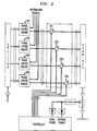
- FIG. 2 An alternative arrangement for preventing high to peak-to-average power ratios from occurring is shown in the FIG. 2.
- the system components are substantially identical to those described with reference to the FIG. 1 system, but their relative positioning is altered.
- the chief alteration is the positioning of the voltage controlled phase shifters 231-234 to phase shift the carrier at the outputs of the transceivers 201 - 204.
- This repositioning requires phase shifts in the order of 60 to 180 degrees to be effective. Otherwise the operation is substantially similar to the operation of the phase shift system of FIG. 1.
- the controller used here is identical to the controller of FIG. 3 except for the phase shift increment used.
Landscapes
- Engineering & Computer Science (AREA)
- Computer Networks & Wireless Communication (AREA)
- Signal Processing (AREA)
- Power Engineering (AREA)
- Amplifiers (AREA)
- Transmitters (AREA)
Abstract
Description
- This invention relates to multi-channel signal amplification systems in a communication system and to a method and apparatus for increasing the average power handling capacity of such a multi-channel signal amplifier relative to its peak power rating. It is also concerned with preventing variations of the phases of individual carrier signals comprising the multiple channel signal from causing occurrences of very high envelope signal peaks in the multichannel signal.
- In wireless telephone communication systems the power signals of many channels are combined into a composite signal. This composite signal is split into many parallel paths and coupled to individual radio transmitters in each parallel path. The output radio transmission signals of the plurality of radio transmitters are combined and amplified in a single poweram- plifier. Individual signal peaks in each of the parallel paths may coincide and cause a composite peak power to occur at the single power amplifier that greatly exceeds its power handling capacity.
- The various radio channels are distributed in frequency with respect to each other in that each operates within a different frequency band. Each channel is FM modulated and hence has a signal of substantially constant amplitude. The peak occurrences of the combined signal is a highly complicated function of the individual carrier frequencies, modulation methods, signal contents and noise. Since the simultaneous occurrence of individual signal peaks can not easily be avoided, a multi-channel signal is subject to power maximums where the peak power significantly exceeds the average power of the envelope due to constructive addition of the individual signals.
- U.S. patent 4,064,464 discloses an amplifier system, including a powerspiitterfordividing an input signal into a plurality of channels and feeding each channel into a plurality of power amplifiers connected in parallel. The several output of the parallel connected power amplifiers are combined into a single output by a subsequent power combiner connected to the paralleled outputs of the power amplifiers. The input to one of the paralleled amplifiers includes a voltage controlled phase shifter that is responsive to a deviation of the power output of the power combiner from a reference value. This feedback arrangement maintains the power output at a regulated value. This is however, an amplification technique having individual amplifiers in each of a plurality of channels rather than amplifying a combined signal of a plurality of channels of radio transmission signals in a single amplifier.
- In accord with the invention peak power in an amplifier, amplifying the power output of a plurality of parallel connected radio transmitters is limited according to the apparatus claim 1 and the method claim 2.
- In the Drawing:
- FIG. 1 is a block schematic of an amplifier system control arrangement to limit the peak to average power ratio;
- FIG. 2 is a block schematic of an another amplifier system control arrangement to limit the peak to average power ratio;
- FIG. 3 is a block schematic of a stored program controller used in the amplifier control systems of FIGS. 1 and 2;
- FIGS. 4 and 5 are graphs of waveforms of envelope power processed by the amplifier system; and
- FIG. 6 is a flow process diagram of the method of reducing the peak to average power ratio.
- An exemplary system for reducing the peak to average power in an amplifier processing a plurality of different signal channels spaced apart in frequency from one another; each channel having a different carrier frequency is shown in the FIG. 1. The apparatus shown is included in a cellular base station in which the phase locked radios each handle a different channel in the channel set assigned to the cell served by the cellular base station.
- A plurality of phase locked radio transceivers, 101, 102, 103 and 104, are connected to receive audio and data designated as information signals. These signals are FM modulated and transmitted at different carrier frequencies for each of the phase locked transceivers. The FM signals (radio frequency output signals) are individually transmitted, via
leads combiner circuit 106 that combines all the modulated carriersignals into a composite modulated signal including all the information supplied to the radios 101-104. This composite signal is applied to the preamplifier 107 and subsequently to alinear amplifier 109 which amplifies the composite signal to a radio transmission level. The linear amplifier output is connected to anantenna 110 for transmission to the cell area. - The frequencies of the carrier signals in each of the radios are synchronized to a reference frequency supplied from a reference signal derived from a
reference frequency generator 121. The output of thereference frequency generator 121 is applied to asignal splitter apparatus 122 wh ich applies the reference frequency signal onto the fourleads phase shifters leads - In this illustrative arrangement the carriers of the transceivers are equally spaced apart in frequency. In this instance, the peak to average reduction is most advantageous. Each radio is locked to the same reference frequency supplied to the leads 123-146. Due to thermal effects in the phase locked loops, the carrier frequencies drift with respect to each other and, as shown in FIG. 4, the peaks of several carriers may coincide in time producing a high peak envelope power in the linear amplifier. In general, the envelope of the combined signals are periodic at the rate of, is the frequency spacing between carriers. These envelope peaks may exist for extended periods of time, which is associated with the thermal draft of the phase locked transceivers.
- The power input to the
linear amplifier 109 is sensed by thecoupling device 151 which is connected to anaverage power detector 152 and apeak power detector 153. The values for average power and peak power are applied to acontroller 161. The Controller, which may be implemented in either digital or analog form, continuously monitors the peak power to average power ratio of the signal processed by thelinear amplifier 109.Controller 161 includes circuitry to evaluate this ratio and uses the information to apply control voltages, vialeads - In the arrangement of FIG. 1, a 1 to 3 degree phase shift of the reference frequency inputs corresponds to a 60 to 180 degree phase shift at the RF outputs since the ratio of the radio frequency to the reference frequency is equal to 60. The phase shift for each individual carrier is applied to the corresponding reference signal input to which the radio carrier is synchronized. In the illustrative embodiment this reference frequency is in the 15 MHz range.
- A typical stored program controller suitable for use as the controller is shown in the FIG. 3. The controller monitors the average and peak envelope powers of the input signal to the Linear amplifier. The average power herein is understood to be the thermal equivalent power, averaged over a time period longer than the fluctuations of the envelope power, perhaps 100 mS. The peak power is that power detected by a classical video diode peak detector, which stores the peak value in a capacitor which decays at a rate somewhat slower than the frequency of occurrence of the peaks.
- By measuring both the peak and average powers, the controller of FIG. 3 can compute the peak to average ratio of the signal and optimize for minimum ratio. The hardware implementation, as shown in the FIG. 3, includes two analog to digital converters, 301 and 302which receive input from peak detector(153 in FIG.1) and an average power detector (152 in FIG. 1) respectively, and apply a digitized version of the peak and average power to a microprocessor. The microprocessor includes associated RAM (304) and ROM (305) memory capacity, which provide memory storage and stored instructions for controlling the processing of the sensed power signals and generating the output control signals to control the phase shifting circuitry (131 - 134 in FIG.1). The microprocessor 303 feeds digital phase shift control signals to one or more of a set of digital to analog converters 331 - 334 which in turn supply analog control signals to control the phase shift circuits 131-134 shown in FIG. 1. While the illustrated controller uses a microprocessor and digital signals it is to be under stood that a completely analog controller can be used, with sample and holds and comparators and op amps.
- Optimization of the peak to average power ratio is done with a successive trial and error procedure, since the correlation between phase of a given radio and the peak to average ratio of the combined radio signal is very complex, and because the absolute phase of a given radio is not easily controllable. The controller adjusts one or more of the phase shifters at a time, then monitors the peak to average ratio. If there is an improvement (decrease) in the peak level. the controller continues phase adjustment in the same direction. When a minimum peak to average ratio is achieved, as evidenced by a dip in the peak power envelope, the controller stops adjustment of that phase shifter and goes on to the next phase shifter in sequence. Each phase shifter is set in sequence, and then the controller repeats the cycle. In some applications it may be sufficient to just monitor the peak value of the power envelope.
- The process of changing the phase of a radio, according to the instructions of the stored program of the controller, for a particular one of the radios N, is shown in flow chart form in the FIG. 6. The flow starts in the terminal 601 and the instructions of
block 603 cause the peak envelope and average power to be measured and the peak envelope to average power ratio to be calculated. The instructions ofdecision block 605 determine if the absolute difference between the most recent peak/average ratio measurement and the previous peak/average ratio measurement is greater than some minimum quantum phase value. This quantum value is an absolute value of phase change below which the phase of the current radio is considered to be optimum. - If the absolute difference in decision block is greater than the minimum quantum phase value the flow proceeds to decision block 609 whose instructions determine the most recent peak/average ratio is greater than the previous peak/average value. If it is not the phase of radio N is changed by some quantum value. The last computed peak/average ratio is made the most recent value in the
block 615 and the flow process returns to theblock 603. - If the response to the evaluation of
decision block 605 is a no answer the flow proceeds to theblock 607 which changes the N designation of the radio being adjusted to the next radio. The phase of this radio is changed as per the instructions ofblock 613. - In response to an affirmative response to decision block 609 the flow proceeds to block 611, whose instructions change the direction of the phase shift implemented. The radio phase is shifted in accord with the instructions of
block 615. - The wave form, of FIG. 4 shows the occurrences of high peaks in the multicarrier signal envelope of the type that limit the peak power handling capacity of a linear amplifier system. The
peaks 401 are significantly higher than theaverage power level 402. - The improvement achieved by the method and apparatus to reduce these peaks is shown in FIG. 5 where the
peaks 501 relative to theaverage power level 502 is much reduced compared to the FIG. 4. - An alternative arrangement for preventing high to peak-to-average power ratios from occurring is shown in the FIG. 2. The system components are substantially identical to those described with reference to the FIG. 1 system, but their relative positioning is altered. The chief alteration is the positioning of the voltage controlled phase shifters 231-234 to phase shift the carrier at the outputs of the transceivers 201 - 204. This repositioning requires phase shifts in the order of 60 to 180 degrees to be effective. Otherwise the operation is substantially similar to the operation of the phase shift system of FIG. 1. The controller used here is identical to the controller of FIG. 3 except for the phase shift increment used.
Claims (2)
Applications Claiming Priority (2)
| Application Number | Priority Date | Filing Date | Title |
|---|---|---|---|
| US07/964,596 US5302914A (en) | 1992-10-20 | 1992-10-20 | Method and apparatus for reducing the peak-to-average power in multi-carrier RF communication systems |
| US964596 | 1992-10-20 |
Publications (3)
| Publication Number | Publication Date |
|---|---|
| EP0594358A2 true EP0594358A2 (en) | 1994-04-27 |
| EP0594358A3 EP0594358A3 (en) | 1994-06-22 |
| EP0594358B1 EP0594358B1 (en) | 1998-03-04 |
Family
ID=25508742
Family Applications (1)
| Application Number | Title | Priority Date | Filing Date |
|---|---|---|---|
| EP93308178A Expired - Lifetime EP0594358B1 (en) | 1992-10-20 | 1993-10-13 | Method and apparatus for reducing the peak-to-average power in multi-carrier RF communication systems |
Country Status (9)
| Country | Link |
|---|---|
| US (1) | US5302914A (en) |
| EP (1) | EP0594358B1 (en) |
| JP (1) | JP2735469B2 (en) |
| AU (1) | AU655375B2 (en) |
| CA (1) | CA2108233C (en) |
| DE (1) | DE69317202T2 (en) |
| ES (1) | ES2114009T3 (en) |
| SG (1) | SG42324A1 (en) |
| TW (1) | TW225620B (en) |
Cited By (20)
| Publication number | Priority date | Publication date | Assignee | Title |
|---|---|---|---|---|
| EP0725510A1 (en) * | 1995-02-02 | 1996-08-07 | Motorola, Inc. | Method and apparatus for reducing peak-to-average requirements in multi-tone communication circuits |
| EP0735731A2 (en) * | 1995-03-31 | 1996-10-02 | Victor Company Of Japan, Limited | Multicarrier modulator demodulator, with arrangements for reducing peak power |
| WO1997024800A1 (en) * | 1995-12-27 | 1997-07-10 | Qualcomm Incorporated | Efficient parallel-stage power amplifier |
| WO1997045987A1 (en) * | 1996-05-24 | 1997-12-04 | Motorola Limited | Filter for multicarrier communication system and method for peak power control therein |
| US5872481A (en) * | 1995-12-27 | 1999-02-16 | Qualcomm Incorporated | Efficient parallel-stage power amplifier |
| WO2000001084A1 (en) * | 1998-06-29 | 2000-01-06 | Nokia Networks Oy | Power control in a multi-carrier radio transmitter |
| US6069526A (en) * | 1998-08-04 | 2000-05-30 | Qualcomm Incorporated | Partial or complete amplifier bypass |
| US6069525A (en) * | 1997-04-17 | 2000-05-30 | Qualcomm Incorporated | Dual-mode amplifier with high efficiency and high linearity |
| GB2364488A (en) * | 2000-06-21 | 2002-01-23 | Element 14 Inc | Peak power reduction |
| CN1083643C (en) * | 1996-01-17 | 2002-04-24 | 摩托罗拉公司 | Method and apparatus for average power control |
| GB2368737A (en) * | 2000-10-31 | 2002-05-08 | Roke Manor Research | Controlling an amplifier for improved efficiency using determinations of the peak and mean values of the output envelope |
| WO2003003685A2 (en) * | 2001-05-01 | 2003-01-09 | Binj Technologies, Inc. | Constant amplitude modulation for dsl |
| EP1330063A1 (en) * | 1994-12-05 | 2003-07-23 | NTT Mobile Communications Network, Inc. | Signal multiplexer |
| EP1365606A1 (en) * | 2001-02-27 | 2003-11-26 | Huawei Technologies Co., Ltd. | The apparatus and method for power control in digital mobile communication system broadband multi-carrier base station |
| EP1596551A1 (en) * | 2004-05-06 | 2005-11-16 | NTT DoCoMo, Inc. | Apparatus for peak to average power ratio reduction in a multicarrier system |
| US7062289B2 (en) | 2001-02-27 | 2006-06-13 | Huawei Technologies Co., Ltd. | Method and apparatus of multi-carrier power control of base station in broad-band digital mobile communication system |
| US7061990B2 (en) | 2000-07-21 | 2006-06-13 | Pmc-Sierra Inc. | Systems and methods for the dynamic range compression of multi-bearer single-carrier and multi-carrier waveforms |
| EP2147322A2 (en) * | 2007-05-14 | 2010-01-27 | Hittite Microwave Corporation | Rf detector with crest factor measurement |
| US8461921B2 (en) | 2009-08-04 | 2013-06-11 | Qualcomm, Incorporated | Amplifier module with multiple operating modes |
| US8536950B2 (en) | 2009-08-03 | 2013-09-17 | Qualcomm Incorporated | Multi-stage impedance matching |
Families Citing this family (101)
| Publication number | Priority date | Publication date | Assignee | Title |
|---|---|---|---|---|
| IT1256225B (en) * | 1992-12-23 | 1995-11-29 | Sits Soc It Telecom Siemens | PROCEDURE AND CIRCUIT FOR THE ADAPTIVE COMPENSATION OF THE GAIN DISTORTIONS OF A MICROWAVE AMPLIFIER WITH LINEARIZER |
| US5551070A (en) * | 1993-01-28 | 1996-08-27 | Telefonaktiebolaget Lm Ericsson | Cartesian multicarrier feedback |
| US5854571A (en) * | 1993-10-28 | 1998-12-29 | Motorola Inc. | Method and apparatus for controlling a peak envelope power of a power amplifier |
| TW293968B (en) * | 1994-09-29 | 1996-12-21 | Radio Frequency Systems Inc | |
| TW280064B (en) * | 1994-09-29 | 1996-07-01 | Radio Frequency Systems Inc | |
| US5570350A (en) * | 1994-09-30 | 1996-10-29 | Lucent Technologies Inc. | CDMA cellular communications with multicarrier signal processing |
| US5625871A (en) * | 1994-09-30 | 1997-04-29 | Lucent Technologies Inc. | Cellular communications system with multicarrier signal processing |
| KR960027576A (en) * | 1994-12-01 | 1996-07-22 | 리차드 탤런 | Wireless Signal Scanning and Targeting System for Land Mobile Wireless Base Sites |
| US5701596A (en) * | 1994-12-01 | 1997-12-23 | Radio Frequency Systems, Inc. | Modular interconnect matrix for matrix connection of a plurality of antennas with a plurality of radio channel units |
| EP0719001A1 (en) * | 1994-12-22 | 1996-06-26 | ALCATEL BELL Naamloze Vennootschap | DMT modulator |
| WO1996026582A1 (en) * | 1995-02-23 | 1996-08-29 | Ntt Mobile Communications Network Inc. | Variable rate transmitting method, and transmitter and receiver using it |
| GB2301751B (en) | 1995-06-02 | 2000-02-09 | Dsc Communications | Control message transmission in telecommunications systems |
| US5745846A (en) * | 1995-08-07 | 1998-04-28 | Lucent Technologies, Inc. | Channelized apparatus for equalizing carrier powers of multicarrier signal |
| GB2309363B (en) * | 1996-01-17 | 2000-07-12 | Motorola Ltd | Multicarrier communication system and method for peak power control |
| US5710990A (en) * | 1996-03-21 | 1998-01-20 | Motorola, Inc. | Transmitter which adjusts peak-to-average power of a multicarrier signal by switching between a group of channels and a phase-adjusted group of channels |
| US5778307A (en) * | 1996-03-29 | 1998-07-07 | Motorola, Inc. | Amplifier with adaptive output allocation and method thereof |
| US5815532A (en) * | 1996-05-01 | 1998-09-29 | Glenayre Electronics, Inc. | Method and apparatus for peak-to-average ratio control in an amplitude modulation paging transmitter |
| US6023612A (en) * | 1996-07-05 | 2000-02-08 | Thomcast Communications, Inc. | Modular transmission system and method |
| US6185182B1 (en) | 1996-07-26 | 2001-02-06 | Radio Frequency Systems, Inc. | Power sharing amplifier system for a cellular communications system |
| DE19635813A1 (en) * | 1996-09-04 | 1998-03-05 | Johannes Prof Dr Ing Huber | Process for reducing the peak value factor in digital transmission processes |
| US5862466A (en) * | 1997-01-09 | 1999-01-19 | Hewlett-Packard Company | Method and apparatus for automatically balancing a radio-frequency mixer |
| US6018644A (en) * | 1997-01-28 | 2000-01-25 | Northrop Grumman Corporation | Low-loss, fault-tolerant antenna interface unit |
| US6501771B2 (en) | 1997-02-11 | 2002-12-31 | At&T Wireless Services, Inc. | Delay compensation |
| US5933421A (en) * | 1997-02-06 | 1999-08-03 | At&T Wireless Services Inc. | Method for frequency division duplex communications |
| US6085114A (en) | 1997-02-06 | 2000-07-04 | At&T Wireless Systems Inc. | Remote wireless unit having reduced power operating mode |
| US6408016B1 (en) * | 1997-02-24 | 2002-06-18 | At&T Wireless Services, Inc. | Adaptive weight update method and system for a discrete multitone spread spectrum communications system |
| US6359923B1 (en) * | 1997-12-18 | 2002-03-19 | At&T Wireless Services, Inc. | Highly bandwidth efficient communications |
| US6584144B2 (en) | 1997-02-24 | 2003-06-24 | At&T Wireless Services, Inc. | Vertical adaptive antenna array for a discrete multitone spread spectrum communications system |
| US6859828B1 (en) * | 1997-02-25 | 2005-02-22 | Agilent Technologies, Inc. | Bi-directional test system for network analysis |
| DE69833198T2 (en) * | 1997-06-17 | 2006-09-21 | Qualcomm, Inc., San Diego | MULTICHANNEL CONNECTION WITH REDUCED TIP TO AVERAGE AMPLITUDE |
| US6175551B1 (en) * | 1997-07-31 | 2001-01-16 | Lucent Technologies, Inc. | Transmission system and method employing peak cancellation to reduce the peak-to-average power ratio |
| US5966048A (en) * | 1997-11-25 | 1999-10-12 | Hughes Electronics Corporation | Low IMD amplification method and apparatus |
| US6512797B1 (en) * | 1998-04-20 | 2003-01-28 | The Board Of Trustees Of The Leland Stanford Junior University | Peak to average power ratio reduction |
| US6314146B1 (en) | 1998-06-05 | 2001-11-06 | The Board Of Trustees Of The Leland Stanford Junior University | Peak to average power ratio reduction |
| US6424681B1 (en) * | 1998-04-20 | 2002-07-23 | The Board Of Trustees Of The Leland Stanford Junior University | Peak to average power ratio reduction |
| JP3462388B2 (en) * | 1998-04-28 | 2003-11-05 | 松下電器産業株式会社 | Wireless communication device |
| US6381212B1 (en) | 1998-06-17 | 2002-04-30 | Radio Frequency Systems, Inc. | Power sharing amplifier system for amplifying multiple input signals with shared power amplifiers |
| US6445747B1 (en) | 1998-07-14 | 2002-09-03 | At&T Corporation | Method and apparatus to reduce peak to average power ratio in multi-carrier modulation |
| US6757299B1 (en) * | 1998-09-24 | 2004-06-29 | Silicon Automation Systems Limited | Peak power to average power ratio reduction in multicarrier communication systems using error-correcting code |
| KR20000039982A (en) * | 1998-12-16 | 2000-07-05 | 김영환 | Apparatus for generating local frequency of base station in cdma communication system |
| US6166601A (en) * | 1999-01-07 | 2000-12-26 | Wiseband Communications Ltd. | Super-linear multi-carrier power amplifier |
| JP2000269919A (en) | 1999-03-16 | 2000-09-29 | Matsushita Electric Ind Co Ltd | Ofdm communication unit |
| EP1087560B1 (en) * | 1999-04-06 | 2008-11-26 | Mitsubishi Denki Kabushiki Kaisha | Cdma type multiple transmission apparatus and cdma type multiple transmission method |
| US6160449A (en) * | 1999-07-22 | 2000-12-12 | Motorola, Inc. | Power amplifying circuit with load adjust for control of adjacent and alternate channel power |
| US6438360B1 (en) | 1999-07-22 | 2002-08-20 | Motorola, Inc. | Amplifier system with load control to produce an amplitude envelope |
| US6166598A (en) * | 1999-07-22 | 2000-12-26 | Motorola, Inc. | Power amplifying circuit with supply adjust to control adjacent and alternate channel power |
| US6349216B1 (en) | 1999-07-22 | 2002-02-19 | Motorola, Inc. | Load envelope following amplifier system |
| US6128350A (en) * | 1999-08-24 | 2000-10-03 | Usa Digital Radio, Inc. | Method and apparatus for reducing peak to average power ratio in digital broadcasting systems |
| US6434135B1 (en) * | 1999-08-31 | 2002-08-13 | Interdigital Technology Corporation | Adaptive RF amplifier prelimiter |
| GB2357647A (en) * | 1999-12-24 | 2001-06-27 | Nokia Networks Oy | Multi-carrier TDMA base station where uniform transmission power across time slots is achieved by a method of allocation of new calls |
| US6825719B1 (en) * | 2000-05-26 | 2004-11-30 | Intel Corporation | RF power amplifier and methods for improving the efficiency thereof |
| US6957087B1 (en) | 2000-10-19 | 2005-10-18 | Telefonaktiebolaget Lm Ericsson (Publ) | Power control in MCPA equipped base stations |
| US6587511B2 (en) * | 2001-01-26 | 2003-07-01 | Intel Corporation | Radio frequency transmitter and methods thereof |
| US6990153B1 (en) * | 2001-02-06 | 2006-01-24 | Agency For Science, Technology And Research | Method and apparatus for semi-blind communication channel estimation |
| US7266354B2 (en) * | 2001-06-25 | 2007-09-04 | Telefonaktiebolaget Lm Ericsson (Publ) | Reducing the peak-to-average power ratio of a communication signal |
| KR100547843B1 (en) * | 2001-07-13 | 2006-02-01 | 삼성전자주식회사 | Apparatus and method for controling transmission power in mobile telecommunications system |
| US7397860B1 (en) | 2001-10-04 | 2008-07-08 | Brooktree Broadband Holding, Inc. | Fractional local peak detection and mitigation for PAR reduction |
| US7136423B1 (en) | 2001-10-04 | 2006-11-14 | Conexant, Inc. | Side tones packets injection (STPI) for PAR reduction |
| US20070211829A1 (en) * | 2001-10-22 | 2007-09-13 | Matsushita Electric Industrial Co., Ltd. | Method and apparatus for pulse optimization for non-linear filtering |
| US7054385B2 (en) * | 2001-10-22 | 2006-05-30 | Tropian, Inc. | Reduction of average-to-minimum power ratio in communications signals |
| US8331490B2 (en) * | 2001-10-22 | 2012-12-11 | Panasonic Corporation | Methods and apparatus for conditioning communications signals based on detection of high-frequency events in polar domain |
| US20030125065A1 (en) * | 2001-12-27 | 2003-07-03 | Ilan Barak | Method and apparatus for generating an output signal |
| US20030123566A1 (en) * | 2001-12-27 | 2003-07-03 | Jaime Hasson | Transmitter having a sigma-delta modulator with a non-uniform polar quantizer and methods thereof |
| US7336753B2 (en) * | 2003-06-26 | 2008-02-26 | Marvell International Ltd. | Transmitter |
| US7912145B2 (en) * | 2003-12-15 | 2011-03-22 | Marvell World Trade Ltd. | Filter for a modulator and methods thereof |
| US7356315B2 (en) * | 2003-12-17 | 2008-04-08 | Intel Corporation | Outphasing modulators and methods of outphasing modulation |
| US7391713B2 (en) * | 2003-12-30 | 2008-06-24 | Kiomars Anvari | Phase rotation technique to reduce Crest Factor of multi-carrier signals |
| TWI249297B (en) * | 2004-01-20 | 2006-02-11 | Realtek Semiconductor Corp | Method and apparatus for peak to average power ratio reduction |
| US7542517B2 (en) | 2004-02-02 | 2009-06-02 | Ibiquity Digital Corporation | Peak-to-average power reduction for FM OFDM transmission |
| JP4469685B2 (en) * | 2004-08-25 | 2010-05-26 | 富士通株式会社 | Output power error absorption circuit and multi-carrier transmitter having the same |
| US7327803B2 (en) | 2004-10-22 | 2008-02-05 | Parkervision, Inc. | Systems and methods for vector power amplification |
| US7355470B2 (en) | 2006-04-24 | 2008-04-08 | Parkervision, Inc. | Systems and methods of RF power transmission, modulation, and amplification, including embodiments for amplifier class transitioning |
| US9106316B2 (en) | 2005-10-24 | 2015-08-11 | Parkervision, Inc. | Systems and methods of RF power transmission, modulation, and amplification |
| US8013675B2 (en) | 2007-06-19 | 2011-09-06 | Parkervision, Inc. | Combiner-less multiple input single output (MISO) amplification with blended control |
| US7911272B2 (en) | 2007-06-19 | 2011-03-22 | Parkervision, Inc. | Systems and methods of RF power transmission, modulation, and amplification, including blended control embodiments |
| US8442460B2 (en) * | 2006-04-10 | 2013-05-14 | Telefonaktiebolaget L M Ericsson (Publ) | Method for compensating signal distortions in composite amplifiers |
| US8031804B2 (en) | 2006-04-24 | 2011-10-04 | Parkervision, Inc. | Systems and methods of RF tower transmission, modulation, and amplification, including embodiments for compensating for waveform distortion |
| US7937106B2 (en) | 2006-04-24 | 2011-05-03 | ParkerVision, Inc, | Systems and methods of RF power transmission, modulation, and amplification, including architectural embodiments of same |
| US7620129B2 (en) | 2007-01-16 | 2009-11-17 | Parkervision, Inc. | RF power transmission, modulation, and amplification, including embodiments for generating vector modulation control signals |
| WO2008144017A1 (en) | 2007-05-18 | 2008-11-27 | Parkervision, Inc. | Systems and methods of rf power transmission, modulation, and amplification |
| WO2009005768A1 (en) | 2007-06-28 | 2009-01-08 | Parkervision, Inc. | Systems and methods of rf power transmission, modulation, and amplification |
| US7595688B2 (en) * | 2007-10-31 | 2009-09-29 | Raytheon Company | High power commutating multiple output amplifier system |
| JP5049305B2 (en) * | 2008-03-10 | 2012-10-17 | アンリツ株式会社 | Frequency converter |
| JP4996644B2 (en) * | 2009-03-30 | 2012-08-08 | アンリツ株式会社 | Frequency converter |
| US8582687B2 (en) * | 2009-06-26 | 2013-11-12 | Plusn, Llc | System and method for controlling combined radio signals |
| WO2011042952A1 (en) * | 2009-10-06 | 2011-04-14 | 富士通株式会社 | Papr (peak-to-average power ratio) determining apparatus and communication apparatus |
| US9461688B2 (en) * | 2010-03-12 | 2016-10-04 | Sunrise Micro Devices, Inc. | Power efficient communications |
| KR20140026458A (en) | 2011-04-08 | 2014-03-05 | 파커비전, 인크. | Systems and methods of rf power transmission, modulation, and amplification |
| EP2715867A4 (en) | 2011-06-02 | 2014-12-17 | Parkervision Inc | Antenna control |
| US9577855B1 (en) * | 2011-07-13 | 2017-02-21 | Softronics, Ltd. | Channelized multicarrier digitizer |
| CN102255699B (en) * | 2011-08-22 | 2013-06-26 | 宁波大学 | Method for framing and modulating anti-fading wireless multimedia broadcast signals |
| US8787873B1 (en) | 2011-11-04 | 2014-07-22 | Plusn Llc | System and method for communicating using bandwidth on demand |
| US9287906B2 (en) * | 2011-12-19 | 2016-03-15 | Nec Corporation | Transmission apparatus and wireless signal transmission method |
| US9313073B2 (en) * | 2012-01-12 | 2016-04-12 | Telefonaktiebolaget L M Ericsson (Publ) | Adaptive phase shift apparatus and method |
| KR20160058855A (en) | 2013-09-17 | 2016-05-25 | 파커비전, 인크. | Method, apparatus and system for rendering an information bearing function of time |
| KR102283357B1 (en) | 2013-11-26 | 2021-07-28 | 플러스엔, 엘엘씨 | System and method for radio frequency carrier aggregation |
| GB201518859D0 (en) * | 2015-10-23 | 2015-12-09 | Airbus Defence & Space Ltd | High-efficiency amplifier |
| WO2018132110A1 (en) * | 2017-01-15 | 2018-07-19 | Ecosense Lighting Inc. | Lighting systems, and systems for determining periodic values of a phase angle of a waveform power input |
| US10483850B1 (en) | 2017-09-18 | 2019-11-19 | Ecosense Lighting Inc. | Universal input-voltage-compatible switched-mode power supply |
| US11032112B2 (en) * | 2019-10-18 | 2021-06-08 | Motorola Solutions, Inc. | Multi-carrier crest factor reduction |
| CN112422093A (en) * | 2020-11-20 | 2021-02-26 | 成都沃特塞恩电子技术有限公司 | Power synthesis method and device, electronic equipment and storage medium |
Citations (3)
| Publication number | Priority date | Publication date | Assignee | Title |
|---|---|---|---|---|
| US4064464A (en) * | 1976-04-13 | 1977-12-20 | Westinghouse Electric Corporation | Amplitude stabilized power amplifier |
| US5045799A (en) * | 1989-09-28 | 1991-09-03 | Rockwell International Corporation | Peak to average power ratio reduction in a power amplifier with multiple carrier input |
| JPH05130191A (en) * | 1991-10-31 | 1993-05-25 | Nippon Motoroola Kk | Peak/average value ratio reduction method by phase control of a multi-subchannel signal |
Family Cites Families (8)
| Publication number | Priority date | Publication date | Assignee | Title |
|---|---|---|---|---|
| US4010426A (en) * | 1975-11-12 | 1977-03-01 | The United States Of America As Represented By The Secretary Of The Air Force | Rf power amplifier parallel redundant system |
| US4370622A (en) * | 1981-03-23 | 1983-01-25 | Rockwell International Corporation | IMD Limiter |
| US4546313A (en) * | 1983-03-14 | 1985-10-08 | The United States Of America As Represented By The United States Department Of Energy | Peak power ratio generator |
| US5043673A (en) * | 1989-03-31 | 1991-08-27 | Mitsubishi Denki Kabushiki Kaisha | Compensating circuit for a high frequency amplifier |
| JP2875811B2 (en) * | 1989-05-19 | 1999-03-31 | 日本電信電話株式会社 | Signal multiplexing circuit |
| JPH03198407A (en) * | 1989-12-26 | 1991-08-29 | Mitsubishi Electric Corp | Linear amplifier |
| CA2046413C (en) * | 1990-07-11 | 1994-01-04 | Shoichi Narahashi | Feed-forward amplifier |
| US5101211A (en) * | 1991-01-10 | 1992-03-31 | Hughes Aircraft Company | Closed loop RF power amplifier output correction circuit |
-
1992
- 1992-10-20 US US07/964,596 patent/US5302914A/en not_active Expired - Lifetime
-
1993
- 1993-10-12 CA CA002108233A patent/CA2108233C/en not_active Expired - Fee Related
- 1993-10-13 ES ES93308178T patent/ES2114009T3/en not_active Expired - Lifetime
- 1993-10-13 EP EP93308178A patent/EP0594358B1/en not_active Expired - Lifetime
- 1993-10-13 DE DE69317202T patent/DE69317202T2/en not_active Expired - Fee Related
- 1993-10-13 SG SG1996000574A patent/SG42324A1/en unknown
- 1993-10-14 AU AU49021/93A patent/AU655375B2/en not_active Ceased
- 1993-10-18 TW TW082108640A patent/TW225620B/zh active
- 1993-10-20 JP JP5261452A patent/JP2735469B2/en not_active Expired - Lifetime
Patent Citations (3)
| Publication number | Priority date | Publication date | Assignee | Title |
|---|---|---|---|---|
| US4064464A (en) * | 1976-04-13 | 1977-12-20 | Westinghouse Electric Corporation | Amplitude stabilized power amplifier |
| US5045799A (en) * | 1989-09-28 | 1991-09-03 | Rockwell International Corporation | Peak to average power ratio reduction in a power amplifier with multiple carrier input |
| JPH05130191A (en) * | 1991-10-31 | 1993-05-25 | Nippon Motoroola Kk | Peak/average value ratio reduction method by phase control of a multi-subchannel signal |
Non-Patent Citations (1)
| Title |
|---|
| PATENT ABSTRACTS OF JAPAN vol. 17, no. 508 (E-1431) 13 September 1993 & JP-A-05 130 191 (NIPPON MOTOROOLA) * |
Cited By (36)
| Publication number | Priority date | Publication date | Assignee | Title |
|---|---|---|---|---|
| EP1330063A1 (en) * | 1994-12-05 | 2003-07-23 | NTT Mobile Communications Network, Inc. | Signal multiplexer |
| US5835536A (en) * | 1995-02-02 | 1998-11-10 | Motorola, Inc. | Method and apparatus for reducing peak-to-average requirements in multi-tone communication circuits |
| EP0725510A1 (en) * | 1995-02-02 | 1996-08-07 | Motorola, Inc. | Method and apparatus for reducing peak-to-average requirements in multi-tone communication circuits |
| EP0735731A3 (en) * | 1995-03-31 | 2000-09-13 | Victor Company Of Japan, Limited | Multicarrier modulator demodulator, with arrangements for reducing peak power |
| EP0735731A2 (en) * | 1995-03-31 | 1996-10-02 | Victor Company Of Japan, Limited | Multicarrier modulator demodulator, with arrangements for reducing peak power |
| WO1997024800A1 (en) * | 1995-12-27 | 1997-07-10 | Qualcomm Incorporated | Efficient parallel-stage power amplifier |
| KR100430323B1 (en) * | 1995-12-27 | 2004-06-16 | 콸콤 인코포레이티드 | Efficient parallel stage power amplifier |
| US5872481A (en) * | 1995-12-27 | 1999-02-16 | Qualcomm Incorporated | Efficient parallel-stage power amplifier |
| US5974041A (en) * | 1995-12-27 | 1999-10-26 | Qualcomm Incorporated | Efficient parallel-stage power amplifier |
| CN1083643C (en) * | 1996-01-17 | 2002-04-24 | 摩托罗拉公司 | Method and apparatus for average power control |
| WO1997045987A1 (en) * | 1996-05-24 | 1997-12-04 | Motorola Limited | Filter for multicarrier communication system and method for peak power control therein |
| US6069525A (en) * | 1997-04-17 | 2000-05-30 | Qualcomm Incorporated | Dual-mode amplifier with high efficiency and high linearity |
| WO2000001084A1 (en) * | 1998-06-29 | 2000-01-06 | Nokia Networks Oy | Power control in a multi-carrier radio transmitter |
| US6701135B2 (en) | 1998-06-29 | 2004-03-02 | Nokia Corporation | Power control in a multi-carrier radio transmitter |
| US6069526A (en) * | 1998-08-04 | 2000-05-30 | Qualcomm Incorporated | Partial or complete amplifier bypass |
| GB2364488A (en) * | 2000-06-21 | 2002-01-23 | Element 14 Inc | Peak power reduction |
| US7409011B2 (en) | 2000-07-21 | 2008-08-05 | Pmc-Sierra, Inc. | Systems and methods for the dynamic range compression of multi-bearer single-carrier and multi-carrier waveforms |
| US7061990B2 (en) | 2000-07-21 | 2006-06-13 | Pmc-Sierra Inc. | Systems and methods for the dynamic range compression of multi-bearer single-carrier and multi-carrier waveforms |
| US7453954B2 (en) | 2000-07-21 | 2008-11-18 | Pmc-Sierra, Inc. | Systems and methods for the reduction of peak to average signal levels of multi-bearer single-carrier and multi-carrier waveforms |
| US7061991B2 (en) | 2000-07-21 | 2006-06-13 | Pmc - Sierra Inc. | Systems and methods for the reduction of peak to average signal levels of multi-bearer single-carrier and multi-carrier waveforms |
| GB2368737B (en) * | 2000-10-31 | 2004-11-10 | Roke Manor Research | Method and apparatus for controlling an amplifier |
| WO2002037668A1 (en) * | 2000-10-31 | 2002-05-10 | Roke Manor Research Limited | Method and apparatus for controlling an amplifier |
| US6952135B2 (en) | 2000-10-31 | 2005-10-04 | Roke Manor Research Limited | Method and apparatus for controlling an amplifier |
| GB2368737A (en) * | 2000-10-31 | 2002-05-08 | Roke Manor Research | Controlling an amplifier for improved efficiency using determinations of the peak and mean values of the output envelope |
| US7062289B2 (en) | 2001-02-27 | 2006-06-13 | Huawei Technologies Co., Ltd. | Method and apparatus of multi-carrier power control of base station in broad-band digital mobile communication system |
| EP1365606A1 (en) * | 2001-02-27 | 2003-11-26 | Huawei Technologies Co., Ltd. | The apparatus and method for power control in digital mobile communication system broadband multi-carrier base station |
| EP1365606A4 (en) * | 2001-02-27 | 2010-05-05 | Huawei Tech Co Ltd | The apparatus and method for power control in digital mobile communication system broadband multi-carrier base station |
| WO2003003685A2 (en) * | 2001-05-01 | 2003-01-09 | Binj Technologies, Inc. | Constant amplitude modulation for dsl |
| WO2003003685A3 (en) * | 2001-05-01 | 2004-02-26 | Binj Technologies Inc | Constant amplitude modulation for dsl |
| EP1596551A1 (en) * | 2004-05-06 | 2005-11-16 | NTT DoCoMo, Inc. | Apparatus for peak to average power ratio reduction in a multicarrier system |
| US7532567B2 (en) | 2004-05-06 | 2009-05-12 | Ntt Docomo, Inc. | Radio communication system, radio transmitter and radio receiver |
| EP2147322A2 (en) * | 2007-05-14 | 2010-01-27 | Hittite Microwave Corporation | Rf detector with crest factor measurement |
| EP2147322A4 (en) * | 2007-05-14 | 2012-04-04 | Hittite Microwave Corp | Rf detector with crest factor measurement |
| US8648588B2 (en) | 2007-05-14 | 2014-02-11 | Hittite Microwave Corporation | RF detector with crest factor measurement |
| US8536950B2 (en) | 2009-08-03 | 2013-09-17 | Qualcomm Incorporated | Multi-stage impedance matching |
| US8461921B2 (en) | 2009-08-04 | 2013-06-11 | Qualcomm, Incorporated | Amplifier module with multiple operating modes |
Also Published As
| Publication number | Publication date |
|---|---|
| JP2735469B2 (en) | 1998-04-02 |
| US5302914A (en) | 1994-04-12 |
| JPH06204959A (en) | 1994-07-22 |
| SG42324A1 (en) | 1997-08-15 |
| EP0594358A3 (en) | 1994-06-22 |
| CA2108233C (en) | 1999-09-28 |
| AU4902193A (en) | 1994-05-05 |
| DE69317202D1 (en) | 1998-04-09 |
| TW225620B (en) | 1994-06-21 |
| CA2108233A1 (en) | 1994-04-21 |
| EP0594358B1 (en) | 1998-03-04 |
| DE69317202T2 (en) | 1998-06-25 |
| ES2114009T3 (en) | 1998-05-16 |
| AU655375B2 (en) | 1994-12-15 |
Similar Documents
| Publication | Publication Date | Title |
|---|---|---|
| EP0594358B1 (en) | Method and apparatus for reducing the peak-to-average power in multi-carrier RF communication systems | |
| EP0594352B1 (en) | Circuitry for minimizing peak power in an amplifier carrying a plurality of signals of differing frequencies | |
| EP1224731B1 (en) | Improved predistortion compensation for a power amplifier | |
| EP0541789B1 (en) | Feed forward amplifier network with frequency swept pilot tone | |
| US7634240B2 (en) | Method and apparatus for controlling a supply voltage to a power amplifier | |
| EP0367458B1 (en) | A predistortion compensated linear amplifier | |
| AU650811B2 (en) | High dynamic range modulation independent feed forward amplifier network | |
| US6463264B1 (en) | Wireless communication apparatus and transmission power control method in wireless communication apparatus | |
| EP1428313B1 (en) | A system and method for minimizing dissipation in rf power amplifiers | |
| US6788744B1 (en) | Power control circuit and transmitter | |
| US6728224B1 (en) | Portable mobile terminal and transmission unit | |
| US6614299B2 (en) | Method and system for automated current balance adjustment for parallel combined amplification elements | |
| US6326840B1 (en) | Feed-forward distortion compensation amplifier and method of amplifying signal with feed-forward distortion compensation | |
| US7190223B2 (en) | Amplifier | |
| JPH09168038A (en) | Radio equipment | |
| US7088176B2 (en) | Method and arrangement relating to multicarrier power amplifiers | |
| JP4130574B2 (en) | Distortion compensation amplifier | |
| JPH07123065A (en) | Time division multiplex access radio equipment |
Legal Events
| Date | Code | Title | Description |
|---|---|---|---|
| PUAI | Public reference made under article 153(3) epc to a published international application that has entered the european phase |
Free format text: ORIGINAL CODE: 0009012 |
|
| AK | Designated contracting states |
Kind code of ref document: A2 Designated state(s): DE ES FR GB IT NL |
|
| PUAL | Search report despatched |
Free format text: ORIGINAL CODE: 0009013 |
|
| AK | Designated contracting states |
Kind code of ref document: A3 Designated state(s): DE ES FR GB IT NL |
|
| RAP3 | Party data changed (applicant data changed or rights of an application transferred) |
Owner name: AT&T CORP. |
|
| 17P | Request for examination filed |
Effective date: 19941208 |
|
| GRAG | Despatch of communication of intention to grant |
Free format text: ORIGINAL CODE: EPIDOS AGRA |
|
| GRAG | Despatch of communication of intention to grant |
Free format text: ORIGINAL CODE: EPIDOS AGRA |
|
| GRAG | Despatch of communication of intention to grant |
Free format text: ORIGINAL CODE: EPIDOS AGRA |
|
| GRAH | Despatch of communication of intention to grant a patent |
Free format text: ORIGINAL CODE: EPIDOS IGRA |
|
| 17Q | First examination report despatched |
Effective date: 19970701 |
|
| GRAH | Despatch of communication of intention to grant a patent |
Free format text: ORIGINAL CODE: EPIDOS IGRA |
|
| GRAA | (expected) grant |
Free format text: ORIGINAL CODE: 0009210 |
|
| AK | Designated contracting states |
Kind code of ref document: B1 Designated state(s): DE ES FR GB IT NL |
|
| ITF | It: translation for a ep patent filed |
Owner name: JACOBACCI & PERANI S.P.A. |
|
| ET | Fr: translation filed | ||
| REF | Corresponds to: |
Ref document number: 69317202 Country of ref document: DE Date of ref document: 19980409 |
|
| REG | Reference to a national code |
Ref country code: ES Ref legal event code: FG2A Ref document number: 2114009 Country of ref document: ES Kind code of ref document: T3 |
|
| PLBE | No opposition filed within time limit |
Free format text: ORIGINAL CODE: 0009261 |
|
| STAA | Information on the status of an ep patent application or granted ep patent |
Free format text: STATUS: NO OPPOSITION FILED WITHIN TIME LIMIT |
|
| 26N | No opposition filed | ||
| PGFP | Annual fee paid to national office [announced via postgrant information from national office to epo] |
Ref country code: NL Payment date: 20000925 Year of fee payment: 8 |
|
| PGFP | Annual fee paid to national office [announced via postgrant information from national office to epo] |
Ref country code: ES Payment date: 20001018 Year of fee payment: 8 |
|
| PGFP | Annual fee paid to national office [announced via postgrant information from national office to epo] |
Ref country code: FR Payment date: 20010925 Year of fee payment: 9 |
|
| PGFP | Annual fee paid to national office [announced via postgrant information from national office to epo] |
Ref country code: GB Payment date: 20011008 Year of fee payment: 9 |
|
| PG25 | Lapsed in a contracting state [announced via postgrant information from national office to epo] |
Ref country code: ES Free format text: LAPSE BECAUSE OF NON-PAYMENT OF DUE FEES Effective date: 20011014 |
|
| PGFP | Annual fee paid to national office [announced via postgrant information from national office to epo] |
Ref country code: DE Payment date: 20011230 Year of fee payment: 9 |
|
| REG | Reference to a national code |
Ref country code: GB Ref legal event code: IF02 |
|
| PG25 | Lapsed in a contracting state [announced via postgrant information from national office to epo] |
Ref country code: NL Free format text: LAPSE BECAUSE OF NON-PAYMENT OF DUE FEES Effective date: 20020501 |
|
| NLV4 | Nl: lapsed or anulled due to non-payment of the annual fee |
Effective date: 20020501 |
|
| PG25 | Lapsed in a contracting state [announced via postgrant information from national office to epo] |
Ref country code: GB Free format text: LAPSE BECAUSE OF NON-PAYMENT OF DUE FEES Effective date: 20021013 |
|
| PG25 | Lapsed in a contracting state [announced via postgrant information from national office to epo] |
Ref country code: DE Free format text: LAPSE BECAUSE OF NON-PAYMENT OF DUE FEES Effective date: 20030501 |
|
| GBPC | Gb: european patent ceased through non-payment of renewal fee |
Effective date: 20021013 |
|
| PG25 | Lapsed in a contracting state [announced via postgrant information from national office to epo] |
Ref country code: FR Free format text: LAPSE BECAUSE OF NON-PAYMENT OF DUE FEES Effective date: 20030630 |
|
| REG | Reference to a national code |
Ref country code: FR Ref legal event code: ST |
|
| REG | Reference to a national code |
Ref country code: ES Ref legal event code: FD2A Effective date: 20021113 |
|
| PG25 | Lapsed in a contracting state [announced via postgrant information from national office to epo] |
Ref country code: IT Free format text: LAPSE BECAUSE OF NON-PAYMENT OF DUE FEES;WARNING: LAPSES OF ITALIAN PATENTS WITH EFFECTIVE DATE BEFORE 2007 MAY HAVE OCCURRED AT ANY TIME BEFORE 2007. THE CORRECT EFFECTIVE DATE MAY BE DIFFERENT FROM THE ONE RECORDED. Effective date: 20051013 |