EP0597260A2 - Needle having true I-beam cross-section - Google Patents
Needle having true I-beam cross-section Download PDFInfo
- Publication number
- EP0597260A2 EP0597260A2 EP93116356A EP93116356A EP0597260A2 EP 0597260 A2 EP0597260 A2 EP 0597260A2 EP 93116356 A EP93116356 A EP 93116356A EP 93116356 A EP93116356 A EP 93116356A EP 0597260 A2 EP0597260 A2 EP 0597260A2
- Authority
- EP
- European Patent Office
- Prior art keywords
- needle
- section
- elongated member
- surgical
- beam cross
- Prior art date
- Legal status (The legal status is an assumption and is not a legal conclusion. Google has not performed a legal analysis and makes no representation as to the accuracy of the status listed.)
- Granted
Links
Images
Classifications
-
- A—HUMAN NECESSITIES
- A61—MEDICAL OR VETERINARY SCIENCE; HYGIENE
- A61B—DIAGNOSIS; SURGERY; IDENTIFICATION
- A61B17/00—Surgical instruments, devices or methods, e.g. tourniquets
- A61B17/04—Surgical instruments, devices or methods, e.g. tourniquets for suturing wounds; Holders or packages for needles or suture materials
- A61B17/06—Needles ; Sutures; Needle-suture combinations; Holders or packages for needles or suture materials
- A61B17/06066—Needles, e.g. needle tip configurations
-
- A—HUMAN NECESSITIES
- A61—MEDICAL OR VETERINARY SCIENCE; HYGIENE
- A61B—DIAGNOSIS; SURGERY; IDENTIFICATION
- A61B17/00—Surgical instruments, devices or methods, e.g. tourniquets
- A61B17/04—Surgical instruments, devices or methods, e.g. tourniquets for suturing wounds; Holders or packages for needles or suture materials
- A61B17/06—Needles ; Sutures; Needle-suture combinations; Holders or packages for needles or suture materials
- A61B17/06004—Means for attaching suture to needle
- A61B2017/06028—Means for attaching suture to needle by means of a cylindrical longitudinal blind bore machined at the suture-receiving end of the needle, e.g. opposite to needle tip
Definitions
- the Field of Art to which this invention relates is surgical needles.
- Surgical needles have been long known in the medical and surgical arts for use with sutures to join tissue at incisions, tears, cuts, and the like.
- a conventional surgical needle typically consists of a shaft member having a sharpened distal piercing tip and a proximal end having a cavity for mounting the end of a surgical suture.
- Surgical needles are known to have various configurations including straight needles and curved needles.
- Surgical needles are required to have various performance characteristics.
- the surgical needles must have good ease of penetration, and, minimal resistance to being pulled through tissue.
- the force required to push a needle through tissue will vary with the particular type of tissue, e.g., skin, muscle, arteries, veins, internal organs, tendons, cartilage, etc.
- Surgical needles may have blunt tips, piercing tips, cutting tips or combination pierc- ing/cutting tips.
- a conventional needle holder typically has a pair of opposed, moveable elongated jaws connected to a pair of handles. The jaws are hinged and moveable with respect to each other and movement is controlled by movement of the handles.
- U.S. Patent No. 4,799,484 discloses a needle having superior ease of penetration with a configuration which provides excellent resistance to slipping and twisting when grasped by a needle holder.
- the needle disclosed in that patent has a configuration referred to as an "I-beam", however, the cross-section of the needle is actually rectangular.
- a surgical needle having an I-beam configuration comprises an elongated member with a distal end and a proximal end.
- a piercing point extends from the distal end, while a cylindrical section, having a cavity therein for receiving a suture, extends from the proximal end.
- the needle may be curved or straight.
- the piercing point may optionally have a cutting edge.
- the cross-section of the elongated member has a true I-beam configuration wherein two opposed, parallel flange members are connected by a perpendicular web member.
- Another aspect of the present invention is the combination of a surgical suture and the above-described surgical needle.
- Yet another aspect of the present invention is a method of suturing mammalian tissue using the above-described surgical needle wherein at least one needle pathway is formed in the tissue by the needle, and the suture is moved through each needle pathway.
- the I-beam configured surgical needles of the present invention have improved resistance to bending and buckling. Surprisingly, the I-beam configured needles do not produce increased drag when pushed or pulled through tissue when compared with needles having conventional cross-sections. In addition, the elongated member section of the needle is easy to grasp with a conventional needle holder. The I-beam configuration resists twisting or turning when engaged in the jaws of a conventional needle holder.
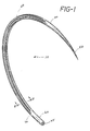
- the surgical needle 10 of the present invention is seen to have a central elongated member 20 having a distal end 40 and a proximal end 30. Extending from the distal end 40 is the piercing point 50. Extending from the proximal end 30 is the cylindrical member section 60 having concentric, internal mounting cavity 65 therein.
- the needle 10 is shown in a curved configuration in FIG. 1, however, it will be appreciated by those skilled in the art that the needle 10 may have other conventional configurations including a straight configuration or a combination of a straight configuration and a curved configuration.
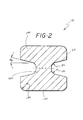
- the needle 10 is seen to have a cross- section of a true I-beam.
- the elongated member 20 is seen to have a pair of opposed, parallel flange members 100 connected by a perpendicular web member 120.
- one or more of the dimensions of member 20 will vary, moving along the member 20, from a maximum dimension to a minimum dimension, as the distal end 40 of needle 10 is approached. However, this variation may not be present or would be significantly attenuated with a cutting edge design.
- One or more of the dimensions of member 20 may also vary from a maximum dimension to a minimum dimension as the proximal end 30 and the tubular member section 60 are approached.
- the dimensions of the web member 100 and the flange members 100, as well as the size of angle A o and the height of the needle 10 cross-section, will vary according to the type of material utilized to manufacture the needle 10 as well as with the particular tissue application for which the needle is designed.
- the dimensions of the web member 100 and the flange members 120 and the size of angle A o and the height of the needle 10 cross-section will be sufficient to provide effective resistance to bending.
- the needles 10 of the present invention may typically have an original diameter of 0.15 mm to about 1.5 mm (i.e., the diameter of the needle prior to forming an I-beam cross-section).
- the length of the needle may vary from about 6 mm to about 65 mm.
- the diameter of the needle will vary depending upon the particular application for which the needle is designed.
- the diameter of the needle 10 may range from 0.15 mm to about 0.5 mm for ophthalmic use and from about 0.15 mm to about 1.5 mm for cardiovascular use.
- the overall height of the needle cross-section may have a dimension of about 0.14 mm to about 1.4 mm.
- the overall width of the flange member 120 may typically be about 0.12 mm to about 1.2 mm.
- the thickness of the flange member may be about 0.05 mm to about 0.5 mm.
- the thickness of the web member 120 may be about 0.07 mm to about 0.80 mm measured at mid-line.
- the height of the web member 120 may be about 0.04 mm to about 0.4 mm measured at its maximum.
- the angle A o as seen in FIG. 2 can vary from about 0 degrees to almost about 90 degrees.
- a o is defined as the angle of declension between the flange and the web member 120.
- Radii r 180 and R 190 are included for alleviation of angles.
- the needle point 50 may have a variety of conventional point configurations including taper point, taper cut, blunt point, cutting edge and spatulated.
- the sutures include absorbable sutures, both natural and synthetic, and, non-absorbable sutures, such as silk, steel and polypropylene.
- the sutures may have diameters ranging from about 11/0 USP ophthalmic to about to 7 USP sternotomy.
- the materials used to manufacture the needles 10 of the present invention include austenitic, martensitic or precipitation hardening stainless steels, or nickel-plated carbon steel. It is particularly preferred to use a conventional stainless steel such as Types AISI 302, 420, and 455.
- the needles 10 of the present invention are manufactured using conventional needle manufacturing techniques in the following manner. Starting with round wire, the wire is straightened and cut into needle blanks. Then, the point 50 is ground or pressed or formed into the distal end 40 using conventional techniques and equipment. The elongated member 20 is then shaped to the desired configuration. The needle 10 is given an I-beam configuration by processing the needle blanks in a conventional mechanical press having dies which form the I-beam configuration into the sides, top and bottom of the needle 10 while holding the needle blank immobile. A hole is drilled or a channel is pressed into the tubular member 60 to form mounting cavity 65. The needle is then curved if a curved configuration is desired. If necessary the needle is then heat treated and electropolished.
- the needles 10 of the present invention may be used to suture tissue in the following conventional procedures including, but not limited to, general wound closure, endoscopic surgery, plastic surgery, microsurgery, cardiovascular, and ophthalmic surgery and equivalents thereof.
- the needles 10 are used in a conventional manner.
- the appropriate size, shape, and needle tip, must produce a controlled hole in tissue to allow passage of the attached suture.
- the needle 10 is typically grasped along elongated member 20 with a conventional needle grasper.
- the point 50 is pushed through tissue until the point 50 is seen to emerge.
- the needle is then released and re- grasped to pull the needle 10 and attached suture through the tissue. The procedure is repeated as required to suture or close the wound or incision.
- a surgical needle 10 of the present invention was fabricated from Type 455 stainless steel alloy.
- the needle 10 had a conventionally curved configuration.
- the needle 10 had an original diameter of 0.46 mm before fabrication of the I beam cross-section.
- the overall height of the I beam cross-section is about 0.51 mm.
- the overall width of the I beam is about 0.41 mm.
- the height of the web member 120 is about 0.18 mm measured at its maximum.
- the width of the web member 120 is about 0.11 mm measured at the mid-line.
- the angle A o of the flange is about 14 degrees.
- a test was performed in which the force needed to bend the needle 10 was measured. This was compared to a needle of 0.46 mm in diameter which was shaped to a rectangle having a thickness of 0.37 mm and a height of 0.42 mm. The needle 10 showed a 41% increase in the force necessary to bend it as compared to the rectangular needle.
- the needle 10 of Example 1 is used to suture a wound in mammalian tissue by initially grasping the elongated member 20 at its center with a conventional needle holder.
- the suture is a size 5/0 Ethibond TI silk or Prolene TM suture manufactured by Ethicon, Inc., Somerville, New Jersey.
- the point 50 is the inserted into the tissue on one side of the wound and pushed into the tissue until the point 50 exits from the tissue on the other side of the wound.
- the needle 10 is released from the needle holder and is then grasped proximal to the point 50 with the needle holder and pulled out of the tissue so that a section of suture remains in the tissue within the pathway created by the needle.
- the needle 10 does not bend or buckle when inserted into the tissue and has a resistance to penetration similar to conventional surgical needles having conventional configurations.
- the elongated member 20 is easily held by the needle holder and does not twist while in the needle holder.
Abstract
Description
- The Field of Art to which this invention relates is surgical needles.
- Surgical needles have been long known in the medical and surgical arts for use with sutures to join tissue at incisions, tears, cuts, and the like. A conventional surgical needle typically consists of a shaft member having a sharpened distal piercing tip and a proximal end having a cavity for mounting the end of a surgical suture. Surgical needles are known to have various configurations including straight needles and curved needles.
- Surgical needles are required to have various performance characteristics. The surgical needles must have good ease of penetration, and, minimal resistance to being pulled through tissue. In addition, it is important for the needle shaft to be resistant to buckling or bending as the surgeon inserts the needle into tissue. Generally speaking, the force required to push a needle through tissue will vary with the particular type of tissue, e.g., skin, muscle, arteries, veins, internal organs, tendons, cartilage, etc. Surgical needles may have blunt tips, piercing tips, cutting tips or combination pierc- ing/cutting tips.
- When using a surgical needle, it is a common practice for the surgeon or physician to grasp the needle with a conventional needle holder. A conventional needle holder typically has a pair of opposed, moveable elongated jaws connected to a pair of handles. The jaws are hinged and moveable with respect to each other and movement is controlled by movement of the handles. When grasping a needle, it is important that the needle not slip within the jaws of the needle holder while the surgeon is attempting to penetrate tissue or pull the needle through tissue. For example, U.S. Patent No. 4,799,484 discloses a needle having superior ease of penetration with a configuration which provides excellent resistance to slipping and twisting when grasped by a needle holder. The needle disclosed in that patent has a configuration referred to as an "I-beam", however, the cross-section of the needle is actually rectangular.
- There is a constant search in this art for needles having improved resistance to bending or buckling while retaining a desirable configuration to reduce the drag on the needle as it is being forced or pushed through tissue.
- Therefore, it is an object of the present invention to provide a surgical needle having a true I-beam configuration.
- It is a further object of the present invention to provide a surgical needle having a configuration which provides improved resistance to bending and buckling while not increasing the drag force required to pull the needle through tissue.
- It is yet a further object of the present invention to provide a surgical needle which is easy to grasp and to hold securely in a conventional needle holder.
- Accordingly, a surgical needle having an I-beam configuration is disclosed. The surgical needle comprises an elongated member with a distal end and a proximal end. A piercing point extends from the distal end, while a cylindrical section, having a cavity therein for receiving a suture, extends from the proximal end. The needle may be curved or straight. The piercing point may optionally have a cutting edge. The cross-section of the elongated member has a true I-beam configuration wherein two opposed, parallel flange members are connected by a perpendicular web member.
- Another aspect of the present invention is the combination of a surgical suture and the above-described surgical needle.
- Yet another aspect of the present invention is a method of suturing mammalian tissue using the above-described surgical needle wherein at least one needle pathway is formed in the tissue by the needle, and the suture is moved through each needle pathway.
- The I-beam configured surgical needles of the present invention have improved resistance to bending and buckling. Surprisingly, the I-beam configured needles do not produce increased drag when pushed or pulled through tissue when compared with needles having conventional cross-sections. In addition, the elongated member section of the needle is easy to grasp with a conventional needle holder. The I-beam configuration resists twisting or turning when engaged in the jaws of a conventional needle holder.
- The foregoing and other features and advantages of the present invention will become more apparent from the following description and accompanying drawings.
-
- FIG. 1 is a perspective view of a surgical needle of the present invention.
- FIG. 2 is a cross-sectional view taken along View Line 2-2 of the surgical needle of the present invention.
- U.S. Patent No. 4,799,484 is incorporated by reference. Referring to FIG.1, the
surgical needle 10 of the present invention is seen to have a centralelongated member 20 having adistal end 40 and aproximal end 30. Extending from thedistal end 40 is thepiercing point 50. Extending from theproximal end 30 is thecylindrical member section 60 having concentric,internal mounting cavity 65 therein. Theneedle 10 is shown in a curved configuration in FIG. 1, however, it will be appreciated by those skilled in the art that theneedle 10 may have other conventional configurations including a straight configuration or a combination of a straight configuration and a curved configuration. - Referring to FIG. 2, the
needle 10 is seen to have a cross- section of a true I-beam. Theelongated member 20 is seen to have a pair of opposed,parallel flange members 100 connected by aperpendicular web member 120. Preferably, one or more of the dimensions ofmember 20 will vary, moving along themember 20, from a maximum dimension to a minimum dimension, as thedistal end 40 ofneedle 10 is approached. However, this variation may not be present or would be significantly attenuated with a cutting edge design. One or more of the dimensions ofmember 20 may also vary from a maximum dimension to a minimum dimension as theproximal end 30 and thetubular member section 60 are approached. - Referring to FIG. 2, it will be appreciated by those skilled in the art that the dimensions of the
web member 100 and theflange members 100, as well as the size of angle Ao and the height of theneedle 10 cross-section, will vary according to the type of material utilized to manufacture theneedle 10 as well as with the particular tissue application for which the needle is designed. The dimensions of theweb member 100 and theflange members 120 and the size of angle Ao and the height of theneedle 10 cross-section will be sufficient to provide effective resistance to bending. - It is well within the purview of one skilled in the art to select the parameters depending upon the particular application and the material of construction of
needle 10. For example, theneedles 10 of the present invention may typically have an original diameter of 0.15 mm to about 1.5 mm (i.e., the diameter of the needle prior to forming an I-beam cross-section). The length of the needle may vary from about 6 mm to about 65 mm. The diameter of the needle will vary depending upon the particular application for which the needle is designed. For example, the diameter of theneedle 10 may range from 0.15 mm to about 0.5 mm for ophthalmic use and from about 0.15 mm to about 1.5 mm for cardiovascular use. The overall height of the needle cross-section may have a dimension of about 0.14 mm to about 1.4 mm. The overall width of theflange member 120 may typically be about 0.12 mm to about 1.2 mm. The thickness of the flange member may be about 0.05 mm to about 0.5 mm. The thickness of theweb member 120 may be about 0.07 mm to about 0.80 mm measured at mid-line. The height of theweb member 120 may be about 0.04 mm to about 0.4 mm measured at its maximum. The angle Ao as seen in FIG. 2 can vary from about 0 degrees to almost about 90 degrees. Ao is defined as the angle of declension between the flange and theweb member 120. Radiir 180 and R 190 are included for alleviation of angles. - The
needle point 50 may have a variety of conventional point configurations including taper point, taper cut, blunt point, cutting edge and spatulated. - Various types of conventional sutures may be used with the
needles 10 of the present invention. The sutures include absorbable sutures, both natural and synthetic, and, non-absorbable sutures, such as silk, steel and polypropylene. The sutures may have diameters ranging from about 11/0 USP ophthalmic to about to 7 USP sternotomy. - The materials used to manufacture the
needles 10 of the present invention include austenitic, martensitic or precipitation hardening stainless steels, or nickel-plated carbon steel. It is particularly preferred to use a conventional stainless steel such as Types AISI 302, 420, and 455. - The
needles 10 of the present invention are manufactured using conventional needle manufacturing techniques in the following manner. Starting with round wire, the wire is straightened and cut into needle blanks. Then, thepoint 50 is ground or pressed or formed into thedistal end 40 using conventional techniques and equipment. Theelongated member 20 is then shaped to the desired configuration. Theneedle 10 is given an I-beam configuration by processing the needle blanks in a conventional mechanical press having dies which form the I-beam configuration into the sides, top and bottom of theneedle 10 while holding the needle blank immobile. A hole is drilled or a channel is pressed into thetubular member 60 to form mountingcavity 65. The needle is then curved if a curved configuration is desired. If necessary the needle is then heat treated and electropolished. - The
needles 10 of the present invention may be used to suture tissue in the following conventional procedures including, but not limited to, general wound closure, endoscopic surgery, plastic surgery, microsurgery, cardiovascular, and ophthalmic surgery and equivalents thereof. - The
needles 10 are used in a conventional manner. The appropriate size, shape, and needle tip, must produce a controlled hole in tissue to allow passage of the attached suture. Theneedle 10 is typically grasped alongelongated member 20 with a conventional needle grasper. Thepoint 50 is pushed through tissue until thepoint 50 is seen to emerge. The needle is then released and re- grasped to pull theneedle 10 and attached suture through the tissue. The procedure is repeated as required to suture or close the wound or incision. - The principles and practice of the present invention are illustrated by the following example although not limited thereto.
- A
surgical needle 10 of the present invention, as illustrated in Fig. 1, was fabricated from Type 455 stainless steel alloy. Theneedle 10 had a conventionally curved configuration. Theneedle 10 had an original diameter of 0.46 mm before fabrication of the I beam cross-section. In the final I-beam configuration the overall height of the I beam cross-section is about 0.51 mm. The overall width of the I beam is about 0.41 mm. The height of theweb member 120 is about 0.18 mm measured at its maximum. The width of theweb member 120 is about 0.11 mm measured at the mid-line. The angle Ao of the flange is about 14 degrees. - A test was performed in which the force needed to bend the
needle 10 was measured. This was compared to a needle of 0.46 mm in diameter which was shaped to a rectangle having a thickness of 0.37 mm and a height of 0.42 mm. Theneedle 10 showed a 41% increase in the force necessary to bend it as compared to the rectangular needle. - The
needle 10 of Example 1 is used to suture a wound in mammalian tissue by initially grasping theelongated member 20 at its center with a conventional needle holder. The suture is a size 5/0 Ethibond TI silk or Prolene TM suture manufactured by Ethicon, Inc., Somerville, New Jersey. Thepoint 50 is the inserted into the tissue on one side of the wound and pushed into the tissue until thepoint 50 exits from the tissue on the other side of the wound. Theneedle 10 is released from the needle holder and is then grasped proximal to thepoint 50 with the needle holder and pulled out of the tissue so that a section of suture remains in the tissue within the pathway created by the needle. Theneedle 10 does not bend or buckle when inserted into the tissue and has a resistance to penetration similar to conventional surgical needles having conventional configurations. Theelongated member 20 is easily held by the needle holder and does not twist while in the needle holder. - Although this invention has been shown and described with respect to detailed embodiments thereof, it will be understood by those skilled in the art that various changes in form and detail thereof may be made without departing from the spirit and scope of the claimed invention.
Claims (10)
Applications Claiming Priority (2)
| Application Number | Priority Date | Filing Date | Title |
|---|---|---|---|
| US959198 | 1992-10-09 | ||
| US07/959,198 US5269806A (en) | 1992-10-09 | 1992-10-09 | I-beam needle having true I-beam cross-section |
Publications (3)
| Publication Number | Publication Date |
|---|---|
| EP0597260A2 true EP0597260A2 (en) | 1994-05-18 |
| EP0597260A3 EP0597260A3 (en) | 1994-07-13 |
| EP0597260B1 EP0597260B1 (en) | 1998-04-22 |
Family
ID=25501767
Family Applications (1)
| Application Number | Title | Priority Date | Filing Date |
|---|---|---|---|
| EP93116356A Expired - Lifetime EP0597260B1 (en) | 1992-10-09 | 1993-10-08 | Needle having true I-beam cross-section |
Country Status (6)
| Country | Link |
|---|---|
| US (1) | US5269806A (en) |
| EP (1) | EP0597260B1 (en) |
| JP (1) | JP3426006B2 (en) |
| BR (1) | BR9304191A (en) |
| DE (1) | DE69318104D1 (en) |
| IL (1) | IL107206A0 (en) |
Cited By (1)
| Publication number | Priority date | Publication date | Assignee | Title |
|---|---|---|---|---|
| EP1078602A2 (en) * | 1999-08-26 | 2001-02-28 | Mani, Inc. | Suturing needle for medical use |
Families Citing this family (73)
| Publication number | Priority date | Publication date | Assignee | Title |
|---|---|---|---|---|
| CN101623206B (en) | 2001-06-14 | 2012-09-26 | 苏太克股份有限公司 | Apparatus and method for surgical suturing with thread management |
| US7185524B2 (en) * | 2003-08-14 | 2007-03-06 | Tyco Healthcare Group Lp | Grindless surgical needle manufacture |
| US20060047309A1 (en) * | 2004-08-25 | 2006-03-02 | Cichocki Frank R Jr | Metal injection molded suture needles |
| US7976555B2 (en) | 2008-07-17 | 2011-07-12 | Endoevolution, Llc | Apparatus and method for minimally invasive suturing |
| US8123764B2 (en) | 2004-09-20 | 2012-02-28 | Endoevolution, Llc | Apparatus and method for minimally invasive suturing |
| US9775600B2 (en) | 2010-10-01 | 2017-10-03 | Endoevolution, Llc | Devices and methods for minimally invasive suturing |
| US7909851B2 (en) | 2006-02-03 | 2011-03-22 | Biomet Sports Medicine, Llc | Soft tissue repair device and associated methods |
| US8118836B2 (en) | 2004-11-05 | 2012-02-21 | Biomet Sports Medicine, Llc | Method and apparatus for coupling soft tissue to a bone |
| US7749250B2 (en) | 2006-02-03 | 2010-07-06 | Biomet Sports Medicine, Llc | Soft tissue repair assembly and associated method |
| US7905904B2 (en) | 2006-02-03 | 2011-03-15 | Biomet Sports Medicine, Llc | Soft tissue repair device and associated methods |
| US8137382B2 (en) | 2004-11-05 | 2012-03-20 | Biomet Sports Medicine, Llc | Method and apparatus for coupling anatomical features |
| US8361113B2 (en) | 2006-02-03 | 2013-01-29 | Biomet Sports Medicine, Llc | Method and apparatus for coupling soft tissue to a bone |
| US8088130B2 (en) | 2006-02-03 | 2012-01-03 | Biomet Sports Medicine, Llc | Method and apparatus for coupling soft tissue to a bone |
| US8840645B2 (en) | 2004-11-05 | 2014-09-23 | Biomet Sports Medicine, Llc | Method and apparatus for coupling soft tissue to a bone |
| US8128658B2 (en) | 2004-11-05 | 2012-03-06 | Biomet Sports Medicine, Llc | Method and apparatus for coupling soft tissue to bone |
| US7857830B2 (en) | 2006-02-03 | 2010-12-28 | Biomet Sports Medicine, Llc | Soft tissue repair and conduit device |
| US9801708B2 (en) | 2004-11-05 | 2017-10-31 | Biomet Sports Medicine, Llc | Method and apparatus for coupling soft tissue to a bone |
| US7601165B2 (en) | 2006-09-29 | 2009-10-13 | Biomet Sports Medicine, Llc | Method and apparatus for forming a self-locking adjustable suture loop |
| US8298262B2 (en) | 2006-02-03 | 2012-10-30 | Biomet Sports Medicine, Llc | Method for tissue fixation |
| US8303604B2 (en) | 2004-11-05 | 2012-11-06 | Biomet Sports Medicine, Llc | Soft tissue repair device and method |
| US9017381B2 (en) | 2007-04-10 | 2015-04-28 | Biomet Sports Medicine, Llc | Adjustable knotless loops |
| US8998949B2 (en) | 2004-11-09 | 2015-04-07 | Biomet Sports Medicine, Llc | Soft tissue conduit device |
| CA2640148C (en) | 2006-01-27 | 2014-09-09 | Suturtek Incorporated | Apparatus and method for tissue closure |
| US8562647B2 (en) | 2006-09-29 | 2013-10-22 | Biomet Sports Medicine, Llc | Method and apparatus for securing soft tissue to bone |
| US8801783B2 (en) | 2006-09-29 | 2014-08-12 | Biomet Sports Medicine, Llc | Prosthetic ligament system for knee joint |
| US9538998B2 (en) | 2006-02-03 | 2017-01-10 | Biomet Sports Medicine, Llc | Method and apparatus for fracture fixation |
| US8251998B2 (en) | 2006-08-16 | 2012-08-28 | Biomet Sports Medicine, Llc | Chondral defect repair |
| US8597327B2 (en) | 2006-02-03 | 2013-12-03 | Biomet Manufacturing, Llc | Method and apparatus for sternal closure |
| US8771352B2 (en) | 2011-05-17 | 2014-07-08 | Biomet Sports Medicine, Llc | Method and apparatus for tibial fixation of an ACL graft |
| US8574235B2 (en) | 2006-02-03 | 2013-11-05 | Biomet Sports Medicine, Llc | Method for trochanteric reattachment |
| US8652172B2 (en) | 2006-02-03 | 2014-02-18 | Biomet Sports Medicine, Llc | Flexible anchors for tissue fixation |
| US10517587B2 (en) | 2006-02-03 | 2019-12-31 | Biomet Sports Medicine, Llc | Method and apparatus for forming a self-locking adjustable loop |
| US9271713B2 (en) | 2006-02-03 | 2016-03-01 | Biomet Sports Medicine, Llc | Method and apparatus for tensioning a suture |
| US8562645B2 (en) | 2006-09-29 | 2013-10-22 | Biomet Sports Medicine, Llc | Method and apparatus for forming a self-locking adjustable loop |
| US11311287B2 (en) | 2006-02-03 | 2022-04-26 | Biomet Sports Medicine, Llc | Method for tissue fixation |
| US9149267B2 (en) | 2006-02-03 | 2015-10-06 | Biomet Sports Medicine, Llc | Method and apparatus for coupling soft tissue to a bone |
| US8506597B2 (en) | 2011-10-25 | 2013-08-13 | Biomet Sports Medicine, Llc | Method and apparatus for interosseous membrane reconstruction |
| US11259792B2 (en) | 2006-02-03 | 2022-03-01 | Biomet Sports Medicine, Llc | Method and apparatus for coupling anatomical features |
| US9078644B2 (en) | 2006-09-29 | 2015-07-14 | Biomet Sports Medicine, Llc | Fracture fixation device |
| US9468433B2 (en) | 2006-02-03 | 2016-10-18 | Biomet Sports Medicine, Llc | Method and apparatus for forming a self-locking adjustable loop |
| US8968364B2 (en) | 2006-02-03 | 2015-03-03 | Biomet Sports Medicine, Llc | Method and apparatus for fixation of an ACL graft |
| US8652171B2 (en) | 2006-02-03 | 2014-02-18 | Biomet Sports Medicine, Llc | Method and apparatus for soft tissue fixation |
| US8500818B2 (en) | 2006-09-29 | 2013-08-06 | Biomet Manufacturing, Llc | Knee prosthesis assembly with ligament link |
| US8672969B2 (en) | 2006-09-29 | 2014-03-18 | Biomet Sports Medicine, Llc | Fracture fixation device |
| US9918826B2 (en) | 2006-09-29 | 2018-03-20 | Biomet Sports Medicine, Llc | Scaffold for spring ligament repair |
| US11259794B2 (en) | 2006-09-29 | 2022-03-01 | Biomet Sports Medicine, Llc | Method for implanting soft tissue |
| US20080312582A1 (en) * | 2007-06-15 | 2008-12-18 | Peter Krulevitch | Method for inserting a flexible medical device conduit |
| US8343227B2 (en) | 2009-05-28 | 2013-01-01 | Biomet Manufacturing Corp. | Knee prosthesis assembly with ligament link |
| US9357991B2 (en) | 2011-11-03 | 2016-06-07 | Biomet Sports Medicine, Llc | Method and apparatus for stitching tendons |
| US9357992B2 (en) | 2011-11-10 | 2016-06-07 | Biomet Sports Medicine, Llc | Method for coupling soft tissue to a bone |
| US9381013B2 (en) | 2011-11-10 | 2016-07-05 | Biomet Sports Medicine, Llc | Method for coupling soft tissue to a bone |
| US9370350B2 (en) | 2011-11-10 | 2016-06-21 | Biomet Sports Medicine, Llc | Apparatus for coupling soft tissue to a bone |
| WO2013165942A1 (en) | 2012-05-01 | 2013-11-07 | Brigham And Women's Hospital, Inc. | Suturing device for laparoscopic procedures |
| US9757119B2 (en) | 2013-03-08 | 2017-09-12 | Biomet Sports Medicine, Llc | Visual aid for identifying suture limbs arthroscopically |
| US9918827B2 (en) | 2013-03-14 | 2018-03-20 | Biomet Sports Medicine, Llc | Scaffold for spring ligament repair |
| US10136886B2 (en) | 2013-12-20 | 2018-11-27 | Biomet Sports Medicine, Llc | Knotless soft tissue devices and techniques |
| US9615822B2 (en) | 2014-05-30 | 2017-04-11 | Biomet Sports Medicine, Llc | Insertion tools and method for soft anchor |
| US9700291B2 (en) | 2014-06-03 | 2017-07-11 | Biomet Sports Medicine, Llc | Capsule retractor |
| US10039543B2 (en) | 2014-08-22 | 2018-08-07 | Biomet Sports Medicine, Llc | Non-sliding soft anchor |
| US9955980B2 (en) | 2015-02-24 | 2018-05-01 | Biomet Sports Medicine, Llc | Anatomic soft tissue repair |
| US9974534B2 (en) | 2015-03-31 | 2018-05-22 | Biomet Sports Medicine, Llc | Suture anchor with soft anchor of electrospun fibers |
| WO2018119459A1 (en) | 2016-12-23 | 2018-06-28 | Brigham And Women's Hospital, Inc. | Systems and methods for suturing tissue |
| US20180242967A1 (en) | 2017-02-26 | 2018-08-30 | Endoevolution, Llc | Apparatus and method for minimally invasive suturing |
| US10292698B2 (en) | 2017-07-27 | 2019-05-21 | Endoevolution, Llc | Apparatus and method for minimally invasive suturing |
| USD937417S1 (en) * | 2019-02-22 | 2021-11-30 | Ethicon, Inc. | Foldable suture needle |
| USD920512S1 (en) * | 2019-02-22 | 2021-05-25 | Ethicon, Inc. | Folded suture needle |
| USD936828S1 (en) * | 2019-02-22 | 2021-11-23 | Ethicon, Inc. | Bendable suture needle |
| US11612392B2 (en) | 2019-02-22 | 2023-03-28 | Ethicon, Inc. | Systems, devices and methods of making highly elastic suture needles for minimally invasive surgery |
| USD895114S1 (en) * | 2019-02-22 | 2020-09-01 | Ethicon, Inc. | Bent suture needle |
| US11234691B2 (en) | 2019-08-13 | 2022-02-01 | Ethicon, Inc. | Composite suture needles having rotatable sections |
| USD912819S1 (en) * | 2019-08-13 | 2021-03-09 | Ethicon, Inc. | Suture needle having a rotatable joint |
| USD912251S1 (en) * | 2019-08-13 | 2021-03-02 | Ethicon, Inc. | Suture needle having a wave shape |
| JP2022025915A (en) * | 2020-07-30 | 2022-02-10 | マニー株式会社 | Medical suture needle |
Citations (2)
| Publication number | Priority date | Publication date | Assignee | Title |
|---|---|---|---|---|
| US2240330A (en) * | 1938-07-11 | 1941-04-29 | Andrew B Flagg | Surgical needle or the like |
| US4799484A (en) * | 1987-04-10 | 1989-01-24 | Ethicon, Inc. | Tapered I-beam surgical needles |
Family Cites Families (5)
| Publication number | Priority date | Publication date | Assignee | Title |
|---|---|---|---|---|
| US1321011A (en) * | 1919-11-04 | Surgical | ||
| US1599059A (en) * | 1925-09-09 | 1926-09-07 | Harry D Morton | Surgical needle and method of making the same |
| US1592897A (en) * | 1925-12-02 | 1926-07-20 | Harry D Morton | Needle and method of making the same |
| US2092929A (en) * | 1934-05-29 | 1937-09-14 | Edward J Ovington | Penetrative implement |
| US3160157A (en) * | 1962-03-29 | 1964-12-08 | Ethicon Inc | Surgical needle |
-
1992
- 1992-10-09 US US07/959,198 patent/US5269806A/en not_active Expired - Lifetime
-
1993
- 1993-10-06 IL IL107206A patent/IL107206A0/en unknown
- 1993-10-08 JP JP27591393A patent/JP3426006B2/en not_active Expired - Fee Related
- 1993-10-08 BR BR9304191A patent/BR9304191A/en unknown
- 1993-10-08 DE DE69318104T patent/DE69318104D1/en not_active Expired - Lifetime
- 1993-10-08 EP EP93116356A patent/EP0597260B1/en not_active Expired - Lifetime
Patent Citations (2)
| Publication number | Priority date | Publication date | Assignee | Title |
|---|---|---|---|---|
| US2240330A (en) * | 1938-07-11 | 1941-04-29 | Andrew B Flagg | Surgical needle or the like |
| US4799484A (en) * | 1987-04-10 | 1989-01-24 | Ethicon, Inc. | Tapered I-beam surgical needles |
Cited By (2)
| Publication number | Priority date | Publication date | Assignee | Title |
|---|---|---|---|---|
| EP1078602A2 (en) * | 1999-08-26 | 2001-02-28 | Mani, Inc. | Suturing needle for medical use |
| EP1078602A3 (en) * | 1999-08-26 | 2001-04-04 | Mani, Inc. | Suturing needle for medical use |
Also Published As
| Publication number | Publication date |
|---|---|
| JP3426006B2 (en) | 2003-07-14 |
| US5269806A (en) | 1993-12-14 |
| EP0597260A3 (en) | 1994-07-13 |
| BR9304191A (en) | 1994-04-12 |
| IL107206A0 (en) | 1994-01-25 |
| EP0597260B1 (en) | 1998-04-22 |
| JPH06205781A (en) | 1994-07-26 |
| DE69318104D1 (en) | 1998-05-28 |
Similar Documents
| Publication | Publication Date | Title |
|---|---|---|
| US5269806A (en) | I-beam needle having true I-beam cross-section | |
| US5897572A (en) | Microsurgical suture needle | |
| US5059207A (en) | Shaped needles for specialized surgical procedures | |
| US8062332B2 (en) | Surgical cobra head suture needle | |
| US5336239A (en) | Surgical needle | |
| US5433728A (en) | Surgical needle | |
| US4524771A (en) | Multiple curved surgical needle | |
| US5797961A (en) | Radiused hollow cutting edge needle | |
| US5693071A (en) | Tapered surgical needles and surgical incision members | |
| US20100146770A1 (en) | Method of manufacturing a barbed surgical suture | |
| US5180385A (en) | Suturing assembly and method | |
| EP1923010B1 (en) | Trocar | |
| US20070219586A1 (en) | Suture Needle and Suture Assembly | |
| AU2003277263B2 (en) | Sharpoint needle | |
| US20030109891A1 (en) | Snared suture trimmer | |
| EP1249211A1 (en) | Surgical incision members for endoscopic suturing apparatus | |
| US7981138B2 (en) | Surgical suture needle |
Legal Events
| Date | Code | Title | Description |
|---|---|---|---|
| PUAI | Public reference made under article 153(3) epc to a published international application that has entered the european phase |
Free format text: ORIGINAL CODE: 0009012 |
|
| AK | Designated contracting states |
Kind code of ref document: A2 Designated state(s): DE FR GB IT |
|
| PUAL | Search report despatched |
Free format text: ORIGINAL CODE: 0009013 |
|
| AK | Designated contracting states |
Kind code of ref document: A3 Designated state(s): DE FR GB IT |
|
| 17P | Request for examination filed |
Effective date: 19941230 |
|
| 17Q | First examination report despatched |
Effective date: 19960327 |
|
| GRAG | Despatch of communication of intention to grant |
Free format text: ORIGINAL CODE: EPIDOS AGRA |
|
| GRAG | Despatch of communication of intention to grant |
Free format text: ORIGINAL CODE: EPIDOS AGRA |
|
| GRAH | Despatch of communication of intention to grant a patent |
Free format text: ORIGINAL CODE: EPIDOS IGRA |
|
| GRAH | Despatch of communication of intention to grant a patent |
Free format text: ORIGINAL CODE: EPIDOS IGRA |
|
| GRAA | (expected) grant |
Free format text: ORIGINAL CODE: 0009210 |
|
| AK | Designated contracting states |
Kind code of ref document: B1 Designated state(s): DE FR GB IT |
|
| PG25 | Lapsed in a contracting state [announced via postgrant information from national office to epo] |
Ref country code: IT Free format text: LAPSE BECAUSE OF FAILURE TO SUBMIT A TRANSLATION OF THE DESCRIPTION OR TO PAY THE FEE WITHIN THE PRESCRIBED TIME-LIMIT;WARNING: LAPSES OF ITALIAN PATENTS WITH EFFECTIVE DATE BEFORE 2007 MAY HAVE OCCURRED AT ANY TIME BEFORE 2007. THE CORRECT EFFECTIVE DATE MAY BE DIFFERENT FROM THE ONE RECORDED. Effective date: 19980422 Ref country code: FR Free format text: LAPSE BECAUSE OF FAILURE TO SUBMIT A TRANSLATION OF THE DESCRIPTION OR TO PAY THE FEE WITHIN THE PRESCRIBED TIME-LIMIT Effective date: 19980422 |
|
| REF | Corresponds to: |
Ref document number: 69318104 Country of ref document: DE Date of ref document: 19980528 |
|
| PG25 | Lapsed in a contracting state [announced via postgrant information from national office to epo] |
Ref country code: DE Free format text: LAPSE BECAUSE OF FAILURE TO SUBMIT A TRANSLATION OF THE DESCRIPTION OR TO PAY THE FEE WITHIN THE PRESCRIBED TIME-LIMIT Effective date: 19980723 |
|
| EN | Fr: translation not filed | ||
| PG25 | Lapsed in a contracting state [announced via postgrant information from national office to epo] |
Ref country code: GB Free format text: LAPSE BECAUSE OF NON-PAYMENT OF DUE FEES Effective date: 19981008 |
|
| PLBE | No opposition filed within time limit |
Free format text: ORIGINAL CODE: 0009261 |
|
| STAA | Information on the status of an ep patent application or granted ep patent |
Free format text: STATUS: NO OPPOSITION FILED WITHIN TIME LIMIT |
|
| 26N | No opposition filed | ||
| GBPC | Gb: european patent ceased through non-payment of renewal fee |
Effective date: 19981008 |