EP0609021A2 - Capacitive position sensor - Google Patents
Capacitive position sensor Download PDFInfo
- Publication number
- EP0609021A2 EP0609021A2 EP94300416A EP94300416A EP0609021A2 EP 0609021 A2 EP0609021 A2 EP 0609021A2 EP 94300416 A EP94300416 A EP 94300416A EP 94300416 A EP94300416 A EP 94300416A EP 0609021 A2 EP0609021 A2 EP 0609021A2
- Authority
- EP
- European Patent Office
- Prior art keywords
- sensor
- electrode
- array
- electrodes
- row
- Prior art date
- Legal status (The legal status is an assumption and is not a legal conclusion. Google has not performed a legal analysis and makes no representation as to the accuracy of the status listed.)
- Withdrawn
Links
- 230000008859 change Effects 0.000 abstract description 7
- 241000699666 Mus <mouse, genus> Species 0.000 description 15
- 238000010586 diagram Methods 0.000 description 7
- 230000000694 effects Effects 0.000 description 5
- 239000011159 matrix material Substances 0.000 description 4
- 230000001360 synchronised effect Effects 0.000 description 4
- 241000699670 Mus sp. Species 0.000 description 3
- 241001422033 Thestylus Species 0.000 description 3
- 239000003990 capacitor Substances 0.000 description 3
- 238000005259 measurement Methods 0.000 description 3
- 238000005070 sampling Methods 0.000 description 2
- PQVHMOLNSYFXIJ-UHFFFAOYSA-N 4-[2-(2,3-dihydro-1H-inden-2-ylamino)pyrimidin-5-yl]-1-[2-oxo-2-(2,4,6,7-tetrahydrotriazolo[4,5-c]pyridin-5-yl)ethyl]pyrazole-3-carboxylic acid Chemical compound C1C(CC2=CC=CC=C12)NC1=NC=C(C=N1)C=1C(=NN(C=1)CC(N1CC2=C(CC1)NN=N2)=O)C(=O)O PQVHMOLNSYFXIJ-UHFFFAOYSA-N 0.000 description 1
- 238000003491 array Methods 0.000 description 1
- 230000008901 benefit Effects 0.000 description 1
- 230000008878 coupling Effects 0.000 description 1
- 238000010168 coupling process Methods 0.000 description 1
- 238000005859 coupling reaction Methods 0.000 description 1
- 230000005484 gravity Effects 0.000 description 1
- 230000036039 immunity Effects 0.000 description 1
- 239000011810 insulating material Substances 0.000 description 1
- 230000002452 interceptive effect Effects 0.000 description 1
- 238000000034 method Methods 0.000 description 1
- 230000008569 process Effects 0.000 description 1
Images


Classifications
-
- G—PHYSICS
- G06—COMPUTING; CALCULATING OR COUNTING
- G06F—ELECTRIC DIGITAL DATA PROCESSING
- G06F3/00—Input arrangements for transferring data to be processed into a form capable of being handled by the computer; Output arrangements for transferring data from processing unit to output unit, e.g. interface arrangements
- G06F3/01—Input arrangements or combined input and output arrangements for interaction between user and computer
- G06F3/03—Arrangements for converting the position or the displacement of a member into a coded form
- G06F3/041—Digitisers, e.g. for touch screens or touch pads, characterised by the transducing means
- G06F3/044—Digitisers, e.g. for touch screens or touch pads, characterised by the transducing means by capacitive means
-
- G—PHYSICS
- G06—COMPUTING; CALCULATING OR COUNTING
- G06F—ELECTRIC DIGITAL DATA PROCESSING
- G06F3/00—Input arrangements for transferring data to be processed into a form capable of being handled by the computer; Output arrangements for transferring data from processing unit to output unit, e.g. interface arrangements
- G06F3/01—Input arrangements or combined input and output arrangements for interaction between user and computer
- G06F3/03—Arrangements for converting the position or the displacement of a member into a coded form
- G06F3/041—Digitisers, e.g. for touch screens or touch pads, characterised by the transducing means
- G06F3/0416—Control or interface arrangements specially adapted for digitisers
-
- G—PHYSICS
- G06—COMPUTING; CALCULATING OR COUNTING
- G06F—ELECTRIC DIGITAL DATA PROCESSING
- G06F3/00—Input arrangements for transferring data to be processed into a form capable of being handled by the computer; Output arrangements for transferring data from processing unit to output unit, e.g. interface arrangements
- G06F3/01—Input arrangements or combined input and output arrangements for interaction between user and computer
- G06F3/048—Interaction techniques based on graphical user interfaces [GUI]
- G06F3/0487—Interaction techniques based on graphical user interfaces [GUI] using specific features provided by the input device, e.g. functions controlled by the rotation of a mouse with dual sensing arrangements, or of the nature of the input device, e.g. tap gestures based on pressure sensed by a digitiser
- G06F3/0488—Interaction techniques based on graphical user interfaces [GUI] using specific features provided by the input device, e.g. functions controlled by the rotation of a mouse with dual sensing arrangements, or of the nature of the input device, e.g. tap gestures based on pressure sensed by a digitiser using a touch-screen or digitiser, e.g. input of commands through traced gestures
- G06F3/04886—Interaction techniques based on graphical user interfaces [GUI] using specific features provided by the input device, e.g. functions controlled by the rotation of a mouse with dual sensing arrangements, or of the nature of the input device, e.g. tap gestures based on pressure sensed by a digitiser using a touch-screen or digitiser, e.g. input of commands through traced gestures by partitioning the display area of the touch-screen or the surface of the digitising tablet into independently controllable areas, e.g. virtual keyboards or menus
Definitions
- This invention relates to sensors for capacitively sensing the position or movement of an object, such as a finger, on a surface.
- U. S. Patent No. 5,113,041 to Greg E. Blonder et al. discloses a computer input tablet for use with a stylus in which the position of the stylus can be determined from signals transmitted to the stylus from a grid of signal lines embedded in the tablet
- U. S. Patent No 4,806,709 to Blair Evans discloses a touch-screen having a resistive layer with a number of point electrodes spaced thereon such that the position of a finger touching the screen can be determined from the relative values of the currents drawn from the point electrodes.
- the first such device requires means for the stylus itself to transmit information, such as a direct electrical connection.
- the second such device, and other kinds of tablets that sense the pressure of a finger or stylus do not require such information-transmitting means.
- Computer input tablets can be used for input of textual or graphical information.
- Various systems are known in the art which process handwritten text as if it were entered on a keyboard. Graphical information can also be captured by means of such tablets.
- joysticks and trackballs can be used with computers to control the position of a cursor on a display screen, such as a video terminal, for input of graphical information and for interactive programs such as computer games and programs using "windows" for display of information. Movement of a mouse in a particular direction on a surface causes a corresponding movement of the cursor or other object on the screen. Similarly, movement of a joystick or trackball in a particular direction causes such movement.
- Input devices such as mice, joysticks and trackballs can be cumbersome because of their size and shape and, particularly with mice, the room needed for use. These drawbacks are more apparent with respect to portable computers, such as the so-called "notebook” computers. It is desirable, therefore, to furnish such control capabilities in an input device that can be incorporated in a small space, but without sacrificing ease of use. It is also desirable to be able to use such a device for multiple functions, for example, a particular area of a computer keyboard that can also be used as a mouse without losing its functionality as a keyboard. Further, it is desirable that such an input device be capable of operation by a finger or handheld stylus that does not require an electrical connection or other means for transmitting information.
- the capacitive sensor of the invention comprises a thin, insulating surface covering a plurality of electrodes.
- the position of an object, such as a finger or hand-held stylus, with respect to the electrodes, is determined from the centroid of capacitance values measured at the electrodes.
- the electrodes can be arranged in one or two dimensions. In a two-dimensional array, the capacitance for each electrode can be measured separately or the electrodes can be divided into separate elements connected in columns and rows and the capacitances measured for each column and row.
- the x and y coordinates of the centroid are calculated in a microcontroller from the measured capacitances.
- the microcontroller forwards position change information to utilizing means.
- the microcontroller identifies a key from the position of the touching object and forwards such key identification to utilizing means.
- FIG. 1 is a graphic diagram showing the relationship between the position of a user's finger and capacitances at electrodes in a two- dimensional sensor constructed in accordance with the invention.
- FIG. 2 is a more detailed representation of interdigitated electrode components at the intersections of rows and columns in a two-dimensional sensor.
- FIG. 3 is an alternate arrangement for electrodes in the array.
- FIG. 4 is an overall block diagram of a two-dimensional capacitive position sensor in accordance with the invention.
- FIG. 5 is a diagram of an integrating amplifier and bootstrap circuit associated with the electrodes.
- FIG. 6 is a flow chart showing operation of the capacitive position sensor of the invention as a computer mouse or trackball.
- FIG. 7 is a diagram showing use of the capacitive position sensor of the invention as a keyboard.
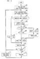
- FIG. 8 is a flow chart showing operation of the capacitive position sensor of the invention as a keyboard.
- the invention will be described in terms of a exemplary two-dimensional embodiment adapted to emulate a computer mouse or keyboard for use with a personal computer. However, it will be clear to those skilled in the art that the principles of the invention can be utilized in other applications in which it is convenient to sense position of an object capacitively in one or more dimensions.
- Electrode array 100 is a square or rectangular array of electrodes 101 arranged in a grid pattern of rows and columns, as in an array of tiles. A 4 x 4 array is shown, which we have found adequate for emulating a computer mouse by finger strokes on the array. However, the invention can be used with arrays of other sizes, if desired.
- the electrodes are covered with a thin layer of insulating material (not shown).
- Finger 102 is shown positioned with respect to array 100.
- Electrode array 100 can be one- dimensional for applications in which position in only one dimension is to be sensed.
- Histogram 110 shows the capacitances for electrodes 101 in array 100 with respect to finger 102.
- Such capacitances are a two- dimensional sampling of the distribution of capacitance between array 100 and finger 102.
- the centroid (center of gravity or first moment) 111 of such distribution will correspond to the position of finger 102, or some other object touching array 100, if suitable sampling criteria are met; that is, by choosing electrodes of sufficiently small size when compared to the extent of the distribution. Such criteria are discussed in the Blonder et al. patent referred to above.
- the x and y coordinates of the centroid can be determined by directly measuring the capacitance at each electrode 101 and calculating such x and y coordinates from such measured capacitances.
- sixteen capacitance measurements would be needed.
- the number of measurements can be reduced, however, by taking advantage of the fact that the one-dimensional centroids of the projections of the distribution onto the x and y axes also correspond to the finger position.
- Such projections can be formed by subdividing each electrode 101 into two elements, as shown in FIG. 2.
- FIG. 2 shows four such subdivided electrodes in more detail at an intersection of two rows and two columns in array 100.
- a horizontal element 201 and a vertical element 202 are situated at each intersection of a row and column.
- Horizontal elements 201 are interconnected by leads 203 and vertical elements 202 are interconnected by leads 204.
- Elements 201 and 202 can be interdigitated as shown. It is advantageous for the conducting areas of elements 201 and 202 to cover the surface of array 100 as completely as possible.
- interdigitated elements 201 and 202 that are approximately 0.37'' square. Smaller electrodes 101 or elements 201 and 202 be desirable for use with a hand-held stylus having a smaller cross-section than a finger.
- elements 201 and 202 can be fabricated in one plane of a multi-layer printed circuit board together with one set of interconnections, for example, the horizontal row connections 203.
- the vertical row connections 204 can then be fabricated in another plane of the circuit board with appropriate via connections between the planes.
- FIG. 3 shows horizontal strip electrodes 203' overlapping vertical strip electrodes 204'. Electrodes 203' and 204' are separated by a thin insulating layer (not shown) and covered by another thin insulating layer (not shown). In such a configuration, areas of electrodes 204' must be left unmasked by electrodes 203' so that electrodes 204' can still "see" the capacitance of an object touching the surface in which such electrodes are embedded.
- a similar configuration of electrodes is shown in the Blonder et al. patent. However, the structure of FIG. 2 is preferred because the interdigitated elements 201 and 202 do not overlap and the capacitance values measured can be higher for a given area of array 100, thus providing greater noise immunity.
- FIG. 4 is an overall block diagram of a capacitive sensor 400 in accordance with the invention.
- Electrode array 100 comprises rows and columns of electrodes, for example, rows and columns of connected horizontal and vertical elements as shown in FIG. 2.
- each row and column of electrodes from array 100 is connected to an integrating amplifier and bootstrap circuit 401, which is shown in more detail in FIG. 5 and will be described below.
- Each of the outputs from circuits 401 can be selected by multiplexer 402 under control of microcontroller 406. The selected output is then forwarded to summing circuit 403, where such output is combined with a signal from trimmer resistor 409.
- Synchronous detector and filter 404 convert the output from summing circuit 403 to a signal related to the capacitance of the row or column selected by multiplexer 402.
- RF oscillator 408 provides an RF signal, for example, 100 kilohertz, to circuits 401, synchronous detector and filter 404 via inverter 410, and guard plane 411.
- Guard plane 411 is a substantially continuous plane parallel to array 100 and associated connections, and serves to isolate array 100 from extraneous signals.
- the operation of synchronous detector and filter 404 is well known in the art, for example, see page 889 of "The Art of Electronics," Second Edition, by Horowitz and Hill, Cambridge University Press (1989).
- Apparatus similar to that shown in FIG. 4 can also be used for applications in which it is desired to measure separate capacitance values for each electrode in array 100 instead of the collective capacitances of subdivided electrode elements connected in rows and columns.
- a circuit 401 is provided for each electrode in array 100 and multiplexer 402 is enlarged to accommodate the outputs from all circuits 401.
- microcontroller 406 can obtain a digital value representing the capacitance seen by any row or column of electrode elements (or electrode if measured separately) selected by multiplexer 402.
- Buttons 407 which can be auxiliary pushbuttons or switches situated near array 400, are also connected to microcontroller 406. Buttons 407 can be used, for example, for the same purposes as the buttons on a computer mouse.
- Microcontroller 407 sends data to utilizing means, such as a personal computer (not shown) over lead 420.
- a particular device that can be used for A/D converter 405 and microcontroller 406 is the 87C552 circuit made by Intel Corporation, which includes both an A/D converter and a microprocessor.
- FIG. 5 is a circuit diagram of each integrating amplifier and bootstrap circuit 401.
- the RF signal from RF oscillator 408 drives the base of transistor Q1 and the bootstrap circuit comprised of resistor 501 and capacitor 502.
- Current source 503 provides a constant DC bias current through transistor Q1.
- An electrode in array 100 is connected to the emitter of transistor Q1.
- the RF current to an electrode is determined by the capacitance seen by the electrode; thus, an increase in capacitance caused by the proximity of an object, such as a finger, causes in increase in such current. Such an increase is reflected as a change in the RF current flowing from the collector of transistor Q1.
- the collector of transistor Q1 is connected to the input node of integrating amplifier 505 via coupling capacitor 506.
- the change in the amplitude of the output signal from amplifier 505 will be approximately A( ⁇ C/C f ), where A is the amplitude of the RF signal from oscillator 408 and C f is the value of integrating capacitor 507.
- Resistor 508 provides a bias current for amplifier 505 and resistor 504 provides bias current for transistor Q1.
- the effects of electrode-to-electrode capacitances, wiring capacitances and other extraneous capacitances are minimized by driving all electrodes and guard plane 411 in unison from RF oscillator 408.
- the bootstrap circuit serves to minimize any signal due to the finite impedance of the biasing circuit of transistor Q1.
- the base-to-collector capacitance of transistors Q1 and other stray capacitances in the circuit can be compensated for by adjusting trim resistor 109 shown in FIG. 1.
- FIG. 6 is a flow chart of the operation of microcontroller 406 in such an application.
- microcomputer 406 reads the initial capacitance values for all the elements in array 100 and stores such values (step 601). Such initial values should reflect the state of array 100 without a finger or other object being nearby, accordingly, it may be desirable to repeat step 601 a number of times and then to select the minimum capacitance values read as the initial values, thereby compensating for the effect of any objects moving close to array 100 during the initialization step. After initialization, all capacitance values are periodically read and the initial values subtracted to yield a remainder value for each element (step 602).
- the x and y coordinates of the centroid of capacitance for such object can be calculated from such remainders (step 604).
- a preset threshold indicating that an object is close to or touching array 100
- the x and y coordinates of the centroid of capacitance for such object can be calculated from such remainders (step 604).
- the electrodes of array 100 are connected in rows and columns, as shown in FIG. 2 and FIG. 3, such calculation can be performed as follows: where: u x is the number of columns, V(n x ) is the value measured for column n x , u y is the number of rows and V(n y ) is the value measured for row n y .
- the threshold can be set to some percentage of the range of A/D converter 405, for example 10-15% of such range.
- the x and y values of the centroid can also be calculated using equations (1) and (2) by adding all the capacitances measured for a row or column to obtain the value of V for such row or column. Such addition has the same effect as if the electrodes were connected together in a row or column.
- the "T" flag When set, the "T" flag indicates that remainders were above the threshold during the previous iteration through step 603. Such flag is set during step 606 and cleared during step 607. Thus, after the first iteration through step 603, indicating a new stroke of finger 102 on array 100, the "T" flag is set and the x and y values just calculated are stored.
- dx x c - x p
- dy y c - y p
- x c and y c are the values just calculated in step 605
- x p and y p are the values calculated and stored (step 610) during the previous iteration.
- the values calculated for x and y are stored (step 610) for use in calculating dx and dy during the next iteration.
- other inputs such as buttons 407
- the state of such inputs is read (step 611).
- data relating to such changes is sent over line 420 to the computer or other utilizing means to which sensor 400 is connected (step 613).
- Such data typically includes dx, dy and the current state of the buttons, which corresponds to that sent to a computer by a conventional computer mouse or trackball.
- the states of such other inputs are stored (step 614) for use during the next iteration.
- cycle time through the above-described steps will be about 20 milliseconds, depending on the time constant of the filter in circuit 404.
- microcontroller 406 is programmed to wait approximately 2 milliseconds for the output of circuit 404 to settle.
- capacitive input sensor 400 can be adapted for use as a general purpose input pad for entering handwritten information.
- buttons 407 for additional input when array sensor 100 is used as a computer mouse, it may be desirable to sense different finger pressures. For example, to perform a "click and drag" operation, a typical use of a computer mouse, a heavier finger pressure can be used on array 100 than when an ordinary cursor movement is desired. Clearly finger pressures can be sensed by electromechanical or other means, but differences in the capacitances sensed by sensor 400 can also be used for this purpose.
- the magnitudes of the capacitance values sensed by array 100 are somewhat related to finger pressure because of the compressibility of the fingertip when contacting array 100. Higher finger pressure will cause higher capacitance values to be sensed. This effect can be enhanced by replacing the insulating layer (not shown) on array 100 with a compressible insulating layer.
- Different finger pressures can be set by defining one or more additional thresholds for use in step 603. An ordinary touch would cause the remainders to exceed only the first threshold; a heavier touch would cause at least one remainder to exceed a higher threshold, which could then be used to indicate a different button state.
- FIG. 7 is a diagram showing how an array 100 can be used as a keyboard in accordance with the invention.
- array 100 is shown as a 4 x 4 matrix of electrodes, but with a keyboard pattern overlay superimposed on the matrix. Such a keyboard pattern can be printed on the insulating layer covering the electrodes. Note that the individual "keys" in the keyboard do not necessarily correspond to the underlying electrodes.
- the x and y coordinates are shown for reference purposes. Since the values obtained for x and y in a 4 x 4 matrix using equations (1) and (2) will range from 1 to 4, this range is shown on the coordinates.
- the identity of a key touched is determined from the x and y values computed for the centroid of capacitance resulting from the touch. For example, using the x and y coordinates shown in FIG. 7, a "5" can be defined as a touch with [1.7 ⁇ x ⁇ 2.3, 2.3 ⁇ y ⁇ 2.7]; a "0" can be defined as a touch with [1 ⁇ x ⁇ 2.3, 1 ⁇ y ⁇ 1.3]; and a "+” can be defined as a touch with [3.7 ⁇ x ⁇ 4, 2.4 ⁇ y ⁇ 3.5]. These ranges are chosen to leave guard bands between adjacent keys.
- FIG. 8 is a flow chart showing operation of microcontroller 406 when the capacitive position sensor of the invention is used as a keyboard.
- Steps 801, 802, 803 and 805 are similar to steps 601, 602, 603 and 604, respectively, in FIG. 6.
- step 806 the identity of the key touched is determined from the values of x and y calculated in step 806.
- step 807 the identity of the key touched is sent to utilizing means.
- the "T" flag is set in step 808, cleared in step 809 and tested in step 804. Such flag assures that the key identity is sent to utilizing means only once.
- a combination mouse-keyboard can be implemented in which one portion of array 100 is used as a mouse responsive to finger strokes and a second portion is used as a keyboard responsive to finger touches.
- array 100 can be adapted to operate in different modes: the first mode as a mouse, the second as a keyboard. Switching between modes can be accomplished, for example, with one of buttons 407, or with extra pressure in a specified region of array 100.
- the capacitive position sensor of the invention can be used as part of the keyboard and also as a mouse.
Abstract
A computer input device for use as a computer mouse or keyboard comprises a thin, insulating surface covering an array of electrodes. Such electrodes are arranged in a grid pattern and can be connected in columns and rows. Each column and row is connected to circuitry for measuring the capacitance seen by each column and row. The position of an object, such as a finger or handheld stylus, with respect to the array is determined from the centroid of such capacitance values, which is calculated in a microcontroller. For applications in which the input device is used as a mouse, the microcontroller forwards position change information to the computer. For applications in which the input device is used as a keyboard, the microcomputer identifies a key from the position of the touching object and forwards such key identity to the computer.
Description
- This invention relates to sensors for capacitively sensing the position or movement of an object, such as a finger, on a surface.
- Numerous devices are known for sensing the position of objects on surfaces, many of which relate to computer input tablets. For example, U. S. Patent No. 5,113,041 to Greg E. Blonder et al. discloses a computer input tablet for use with a stylus in which the position of the stylus can be determined from signals transmitted to the stylus from a grid of signal lines embedded in the tablet, and U. S. Patent No 4,806,709 to Blair Evans discloses a touch-screen having a resistive layer with a number of point electrodes spaced thereon such that the position of a finger touching the screen can be determined from the relative values of the currents drawn from the point electrodes. The first such device requires means for the stylus itself to transmit information, such as a direct electrical connection. The second such device, and other kinds of tablets that sense the pressure of a finger or stylus, do not require such information-transmitting means.
- Computer input tablets can be used for input of textual or graphical information. Various systems are known in the art which process handwritten text as if it were entered on a keyboard. Graphical information can also be captured by means of such tablets.
- Other input devices such as computer "mice," joysticks and trackballs can be used with computers to control the position of a cursor on a display screen, such as a video terminal, for input of graphical information and for interactive programs such as computer games and programs using "windows" for display of information. Movement of a mouse in a particular direction on a surface causes a corresponding movement of the cursor or other object on the screen. Similarly, movement of a joystick or trackball in a particular direction causes such movement.
- Input devices such as mice, joysticks and trackballs can be cumbersome because of their size and shape and, particularly with mice, the room needed for use. These drawbacks are more apparent with respect to portable computers, such as the so-called "notebook" computers. It is desirable, therefore, to furnish such control capabilities in an input device that can be incorporated in a small space, but without sacrificing ease of use. It is also desirable to be able to use such a device for multiple functions, for example, a particular area of a computer keyboard that can also be used as a mouse without losing its functionality as a keyboard. Further, it is desirable that such an input device be capable of operation by a finger or handheld stylus that does not require an electrical connection or other means for transmitting information.
- The capacitive sensor of the invention comprises a thin, insulating surface covering a plurality of electrodes. The position of an object, such as a finger or hand-held stylus, with respect to the electrodes, is determined from the centroid of capacitance values measured at the electrodes. The electrodes can be arranged in one or two dimensions. In a two-dimensional array, the capacitance for each electrode can be measured separately or the electrodes can be divided into separate elements connected in columns and rows and the capacitances measured for each column and row. The x and y coordinates of the centroid are calculated in a microcontroller from the measured capacitances. For applications in which the sensor is used to emulate a mouse or trackball, the microcontroller forwards position change information to utilizing means. For applications in which the sensor is used to emulate a keyboard, the microcontroller identifies a key from the position of the touching object and forwards such key identification to utilizing means.
- These and other aspects of the invention will become apparent from the attached drawings and detailed description.
- FIG. 1 is a graphic diagram showing the relationship between the position of a user's finger and capacitances at electrodes in a two- dimensional sensor constructed in accordance with the invention.
- FIG. 2 is a more detailed representation of interdigitated electrode components at the intersections of rows and columns in a two-dimensional sensor.
- FIG. 3 is an alternate arrangement for electrodes in the array.
- FIG. 4 is an overall block diagram of a two-dimensional capacitive position sensor in accordance with the invention.
- FIG. 5 is a diagram of an integrating amplifier and bootstrap circuit associated with the electrodes.
- FIG. 6 is a flow chart showing operation of the capacitive position sensor of the invention as a computer mouse or trackball.
- FIG. 7 is a diagram showing use of the capacitive position sensor of the invention as a keyboard.
- FIG. 8 is a flow chart showing operation of the capacitive position sensor of the invention as a keyboard.
- The invention will be described in terms of a exemplary two-dimensional embodiment adapted to emulate a computer mouse or keyboard for use with a personal computer. However, it will be clear to those skilled in the art that the principles of the invention can be utilized in other applications in which it is convenient to sense position of an object capacitively in one or more dimensions.
- The operational principle of the capacitive position sensor of the invention is shown in FIG. 1.
Electrode array 100 is a square or rectangular array ofelectrodes 101 arranged in a grid pattern of rows and columns, as in an array of tiles. A 4 x 4 array is shown, which we have found adequate for emulating a computer mouse by finger strokes on the array. However, the invention can be used with arrays of other sizes, if desired. The electrodes are covered with a thin layer of insulating material (not shown).Finger 102 is shown positioned with respect toarray 100.Electrode array 100 can be one- dimensional for applications in which position in only one dimension is to be sensed. -
Histogram 110 shows the capacitances forelectrodes 101 inarray 100 with respect tofinger 102. Such capacitances are a two- dimensional sampling of the distribution of capacitance betweenarray 100 andfinger 102. The centroid (center of gravity or first moment) 111 of such distribution will correspond to the position offinger 102, or some otherobject touching array 100, if suitable sampling criteria are met; that is, by choosing electrodes of sufficiently small size when compared to the extent of the distribution. Such criteria are discussed in the Blonder et al. patent referred to above. - The x and y coordinates of the centroid can be determined by directly measuring the capacitance at each
electrode 101 and calculating such x and y coordinates from such measured capacitances. Thus, for the 4 x 4array 100, sixteen capacitance measurements would be needed. The number of measurements can be reduced, however, by taking advantage of the fact that the one-dimensional centroids of the projections of the distribution onto the x and y axes also correspond to the finger position. Such projections can be formed by subdividing eachelectrode 101 into two elements, as shown in FIG. 2. - FIG. 2 shows four such subdivided electrodes in more detail at an intersection of two rows and two columns in
array 100. As can be seen from FIG. 2, ahorizontal element 201 and avertical element 202 are situated at each intersection of a row and column.Horizontal elements 201 are interconnected byleads 203 andvertical elements 202 are interconnected byleads 204.Elements elements array 100 as completely as possible. For finger strokes, we have used interdigitatedelements Smaller electrodes 101 orelements - As will be clear to those skilled in the art,
elements horizontal row connections 203. Thevertical row connections 204 can then be fabricated in another plane of the circuit board with appropriate via connections between the planes. - Other electrode array configurations can be used, if desired. For example, FIG. 3 shows horizontal strip electrodes 203' overlapping vertical strip electrodes 204'. Electrodes 203' and 204' are separated by a thin insulating layer (not shown) and covered by another thin insulating layer (not shown). In such a configuration, areas of electrodes 204' must be left unmasked by electrodes 203' so that electrodes 204' can still "see" the capacitance of an object touching the surface in which such electrodes are embedded. A similar configuration of electrodes is shown in the Blonder et al. patent. However, the structure of FIG. 2 is preferred because the
interdigitated elements array 100, thus providing greater noise immunity. - FIG. 4 is an overall block diagram of a capacitive sensor 400 in accordance with the invention.
Electrode array 100 comprises rows and columns of electrodes, for example, rows and columns of connected horizontal and vertical elements as shown in FIG. 2. Referring again to FIG. 4, each row and column of electrodes fromarray 100 is connected to an integrating amplifier andbootstrap circuit 401, which is shown in more detail in FIG. 5 and will be described below. Each of the outputs fromcircuits 401 can be selected bymultiplexer 402 under control ofmicrocontroller 406. The selected output is then forwarded to summingcircuit 403, where such output is combined with a signal fromtrimmer resistor 409. Synchronous detector and filter 404 convert the output from summingcircuit 403 to a signal related to the capacitance of the row or column selected bymultiplexer 402.RF oscillator 408 provides an RF signal, for example, 100 kilohertz, tocircuits 401, synchronous detector and filter 404 viainverter 410, andguard plane 411.Guard plane 411 is a substantially continuous plane parallel toarray 100 and associated connections, and serves to isolatearray 100 from extraneous signals. The operation of synchronous detector andfilter 404 is well known in the art, for example, see page 889 of "The Art of Electronics," Second Edition, by Horowitz and Hill, Cambridge University Press (1989). - Apparatus similar to that shown in FIG. 4 can also be used for applications in which it is desired to measure separate capacitance values for each electrode in
array 100 instead of the collective capacitances of subdivided electrode elements connected in rows and columns. To measure such capacitances separately, acircuit 401 is provided for each electrode inarray 100 andmultiplexer 402 is enlarged to accommodate the outputs from allcircuits 401. - The output of synchronous detector and
filter 404 is converted to digital form by analog-to-digital converter 405 and forwarded tomicrocontroller 406. Thus,microcontroller 406 can obtain a digital value representing the capacitance seen by any row or column of electrode elements (or electrode if measured separately) selected bymultiplexer 402.Buttons 407, which can be auxiliary pushbuttons or switches situated near array 400, are also connected tomicrocontroller 406.Buttons 407 can be used, for example, for the same purposes as the buttons on a computer mouse.Microcontroller 407 sends data to utilizing means, such as a personal computer (not shown) overlead 420. A particular device that can be used for A/D converter 405 andmicrocontroller 406 is the 87C552 circuit made by Intel Corporation, which includes both an A/D converter and a microprocessor. - FIG. 5 is a circuit diagram of each integrating amplifier and
bootstrap circuit 401. The RF signal fromRF oscillator 408 drives the base of transistor Q1 and the bootstrap circuit comprised ofresistor 501 andcapacitor 502. Current source 503 provides a constant DC bias current through transistor Q1. An electrode inarray 100 is connected to the emitter of transistor Q1. The RF current to an electrode is determined by the capacitance seen by the electrode; thus, an increase in capacitance caused by the proximity of an object, such as a finger, causes in increase in such current. Such an increase is reflected as a change in the RF current flowing from the collector of transistor Q1. The collector of transistor Q1 is connected to the input node of integratingamplifier 505 viacoupling capacitor 506. For a change in capacitance, ΔC, at the electrode, the change in the amplitude of the output signal fromamplifier 505 will be approximately A(ΔC/Cf), where A is the amplitude of the RF signal fromoscillator 408 and Cf is the value of integratingcapacitor 507.Resistor 508 provides a bias current foramplifier 505 andresistor 504 provides bias current for transistor Q1. - The effects of electrode-to-electrode capacitances, wiring capacitances and other extraneous capacitances are minimized by driving all electrodes and
guard plane 411 in unison fromRF oscillator 408. The bootstrap circuit serves to minimize any signal due to the finite impedance of the biasing circuit of transistor Q1. The base-to-collector capacitance of transistors Q1 and other stray capacitances in the circuit can be compensated for by adjusting trim resistor 109 shown in FIG. 1. - In using the position sensor of the invention as a computer mouse or trackball to control a cursor, movement of the mouse or trackball is emulated by touching
array 100 withfinger 102, or some other object, and strokingfinger 102 overarray 100 to move the cursor. Changes in position of the finger with respect toarray 100 are reflected in corresponding changes in position of the cursor. Thus, for such an application,microcontroller 406 sends data overlead 420 relating to changes in position. FIG. 6 is a flow chart of the operation ofmicrocontroller 406 in such an application. - Referring to FIG. 6,
microcomputer 406 reads the initial capacitance values for all the elements inarray 100 and stores such values (step 601). Such initial values should reflect the state ofarray 100 without a finger or other object being nearby, accordingly, it may be desirable to repeat step 601 a number of times and then to select the minimum capacitance values read as the initial values, thereby compensating for the effect of any objects moving close toarray 100 during the initialization step. After initialization, all capacitance values are periodically read and the initial values subtracted to yield a remainder value for each element (step 602). If one or more of the remainders exceeds a preset threshold (step 603), indicating that an object is close to or touchingarray 100, then the x and y coordinates of the centroid of capacitance for such object can be calculated from such remainders (step 604). For applications in which the electrodes ofarray 100 are connected in rows and columns, as shown in FIG. 2 and FIG. 3, such calculation can be performed as follows:

where:
ux is the number of columns, V(nx) is the value measured for column nx, uy is the number of rows and V(ny) is the value measured for row ny. To avoid spurious operation, it may be desirable to require that two or more measurements exceed the preset threshold. The threshold can be set to some percentage of the range of A/D converter 405, for example 10-15% of such range. - For applications in which the capacitance values for the
electrode 101 inarray 100 are measured separately, the x and y values of the centroid can also be calculated using equations (1) and (2) by adding all the capacitances measured for a row or column to obtain the value of V for such row or column. Such addition has the same effect as if the electrodes were connected together in a row or column. - When set, the "T" flag indicates that remainders were above the threshold during the previous iteration through
step 603. Such flag is set duringstep 606 and cleared duringstep 607. Thus, after the first iteration throughstep 603, indicating a new stroke offinger 102 onarray 100, the "T" flag is set and the x and y values just calculated are stored. During each subsequent iteration during such stroke, the changes in x and y (dx and dy) are calculated (step 608) as follows:

where xc and yc are the values just calculated instep 605 and xp and yp are the values calculated and stored (step 610) during the previous iteration. - It may be desirable to remove jitter from the least-significant bit in the values of dx and dy calculated (step 609). This can be accomplished by incrementing negative values by 1 and decrementing positive values by 1, leaving zero values without change.
- The values calculated for x and y are stored (step 610) for use in calculating dx and dy during the next iteration. Then, if other inputs, such as
buttons 407, are connected tomicrocontroller 406, the state of such inputs is read (step 611). Finally, if x and y have changed (dx≠0 or dy≠0) or the state ofbuttons 407 has changed (step 612), data relating to such changes is sent overline 420 to the computer or other utilizing means to which sensor 400 is connected (step 613). Such data typically includes dx, dy and the current state of the buttons, which corresponds to that sent to a computer by a conventional computer mouse or trackball. Finally the states of such other inputs are stored (step 614) for use during the next iteration. - Typically the cycle time through the above-described steps will be about 20 milliseconds, depending on the time constant of the filter in
circuit 404. After each change ofmultiplexer 402,microcontroller 406 is programmed to wait approximately 2 milliseconds for the output ofcircuit 404 to settle. - It will be clear that the absolute values of x and y can be included in the data sent over
line 420 to utilizing means, if desired. For example, capacitive input sensor 400 can be adapted for use as a general purpose input pad for entering handwritten information. For such an application, it may be desirable to increase the number of electrodes to improve definition, but even a 4x4 matrix for use with finger input can produce useful input data because of the interpolating effect of the centroid-finding calculations performed instep 604. - Instead of using
buttons 407 for additional input whenarray sensor 100 is used as a computer mouse, it may be desirable to sense different finger pressures. For example, to perform a "click and drag" operation, a typical use of a computer mouse, a heavier finger pressure can be used onarray 100 than when an ordinary cursor movement is desired. Clearly finger pressures can be sensed by electromechanical or other means, but differences in the capacitances sensed by sensor 400 can also be used for this purpose. - The magnitudes of the capacitance values sensed by
array 100 are somewhat related to finger pressure because of the compressibility of the fingertip when contactingarray 100. Higher finger pressure will cause higher capacitance values to be sensed. This effect can be enhanced by replacing the insulating layer (not shown) onarray 100 with a compressible insulating layer. Different finger pressures can be set by defining one or more additional thresholds for use instep 603. An ordinary touch would cause the remainders to exceed only the first threshold; a heavier touch would cause at least one remainder to exceed a higher threshold, which could then be used to indicate a different button state. - FIG. 7 is a diagram showing how an
array 100 can be used as a keyboard in accordance with the invention. Again,array 100 is shown as a 4 x 4 matrix of electrodes, but with a keyboard pattern overlay superimposed on the matrix. Such a keyboard pattern can be printed on the insulating layer covering the electrodes. Note that the individual "keys" in the keyboard do not necessarily correspond to the underlying electrodes. The x and y coordinates are shown for reference purposes. Since the values obtained for x and y in a 4 x 4 matrix using equations (1) and (2) will range from 1 to 4, this range is shown on the coordinates. - The identity of a key touched is determined from the x and y values computed for the centroid of capacitance resulting from the touch. For example, using the x and y coordinates shown in FIG. 7, a "5" can be defined as a touch with [1.7≦x≦2.3, 2.3≦y≦2.7]; a "0" can be defined as a touch with [1≦x≦2.3, 1≦y≦1.3]; and a "+" can be defined as a touch with [3.7≦x≦4, 2.4≦y≦3.5]. These ranges are chosen to leave guard bands between adjacent keys.
- FIG. 8 is a flow chart showing operation of
microcontroller 406 when the capacitive position sensor of the invention is used as a keyboard.Steps steps step 806, the identity of the key touched is determined from the values of x and y calculated instep 806. Instep 807, the identity of the key touched is sent to utilizing means. The "T" flag is set instep 808, cleared instep 809 and tested instep 804. Such flag assures that the key identity is sent to utilizing means only once. - It should be clear that the various ways described above of using the capacitive position sensor of the invention can be combined. For example, a combination mouse-keyboard can be implemented in which one portion of
array 100 is used as a mouse responsive to finger strokes and a second portion is used as a keyboard responsive to finger touches. Alternatively,array 100 can be adapted to operate in different modes: the first mode as a mouse, the second as a keyboard. Switching between modes can be accomplished, for example, with one ofbuttons 407, or with extra pressure in a specified region ofarray 100. Thus, where space is at a premium, such as in a portable computer, the capacitive position sensor of the invention can be used as part of the keyboard and also as a mouse. - The invention has been shown and described with reference to particular embodiments. However, it will be understood by those skilled in the art that various changes may be made therein without departing from the spirit and scope of the invention.
Claims (10)
- A sensor (100) for capacitively sensing the position of an object on a surface, which includes an array of electrodes (101) on said surface, an insulating layer covering said electrodes and means (401, 402, 403, 404, 405, 408, 409, 410) for measuring a capacitance value for each said electrode;
CHARACTERIZED BY
means (406) operative when at least one of said capacitance values exceeds a first preset threshold for determining the position of said object by calculating the centroid of capacitance for said array from said measured capacitance values and
means (406) for sending said position to utilizing means. - The sensor of claim 1
CHARACTERIZED IN THAT
said array is a two-dimensional array and said electrodes are arranged in rows and columns. - The sensor of claim 1
CHARACTERIZED IN THAT
said calculating means periodically calculates changes in said position and said sending means periodically sends said changes to said utilizing means. - The sensor of claim 2
FURTHER CHARACTERIZED IN THAT
said sensor is adapted for use as a keyboard wherein said means for calculating further comprises:
a stored range of coordinates (in 406) for each key in said keyboard;
means for determining a key identity from said calculated position and said stored range and said sending means sends said key identity to said utilizing means. - The sensor of claim 1
FURTHER CHARACTERIZED BY
means operative when at least one of said capacitance values exceeds at least a second preset threshold for indicating to said utilizing means the thresholds exceeded. - The sensor of claim 2
FURTHER CHARACTERIZED BY
at each intersection of a row and a column, a first electrode element is connected to other electrode elements in said row, thereby forming the electrode for said row, and a second electrode element is connected to other electrode elements in said column, thereby forming the electrode for said column. - The sensor of claim 6
FURTHER CHARACTERIZED BY
said first and second electrode elements at each intersection are interdigitated. - The sensor of claim 1
FURTHER CHARACTERIZED IN THAT
said measuring means further comprises:
means (408) for supplying an RF signal in unison to each said electrode,
means (401) for sensing RF current signals for each said electrode, and
means (403, 404, 409, 410) for converting said RF current signals into signals representative of the capacitances seen by each said electrode. - The sensor of claim 8
FURTHER CHARACTERIZED BY
a guard plane (411) substantially parallel to said electrodes, and said means for supplying further comprises:
means for supplying said RF signal to said guard plane in unison with the RF signals supplied to said electrodes. - The sensor of any of claims 1-9
CHARACTERIZED IN THAT
said sensor is adapted for use as a touch-sensitive input device for a computer.
Applications Claiming Priority (2)
| Application Number | Priority Date | Filing Date | Title |
|---|---|---|---|
| US11040 | 1993-01-29 | ||
| US08/011,040 US5463388A (en) | 1993-01-29 | 1993-01-29 | Computer mouse or keyboard input device utilizing capacitive sensors |
Publications (2)
| Publication Number | Publication Date |
|---|---|
| EP0609021A2 true EP0609021A2 (en) | 1994-08-03 |
| EP0609021A3 EP0609021A3 (en) | 1994-10-12 |
Family
ID=21748605
Family Applications (1)
| Application Number | Title | Priority Date | Filing Date |
|---|---|---|---|
| EP19940300416 Withdrawn EP0609021A3 (en) | 1993-01-29 | 1994-01-19 | Capacitive position sensor. |
Country Status (5)
| Country | Link |
|---|---|
| US (1) | US5463388A (en) |
| EP (1) | EP0609021A3 (en) |
| JP (1) | JPH06242875A (en) |
| KR (1) | KR940018729A (en) |
| TW (1) | TW229287B (en) |
Cited By (40)
| Publication number | Priority date | Publication date | Assignee | Title |
|---|---|---|---|---|
| WO1995027334A1 (en) * | 1994-04-05 | 1995-10-12 | Ronald Peter Binstead | Multiple input proximity detector and touchpad system |
| WO1996007981A1 (en) * | 1994-09-02 | 1996-03-14 | Synaptics, Inc. | Object position detector |
| WO1996007966A1 (en) * | 1994-09-02 | 1996-03-14 | Synaptics, Inc. | Object position detector with edge motion feature |
| EP0727875A1 (en) * | 1995-01-20 | 1996-08-21 | Dynapro Systems, Inc. | Capacitive touch sensor |
| DE19642615A1 (en) * | 1995-10-20 | 1997-04-24 | Kws Computersysteme Gmbh | Machine control input device |
| WO1997031238A1 (en) * | 1996-02-23 | 1997-08-28 | Massachusetts Institute Of Technology | Displacement-current method and apparatus for resolving presence, orientation and activity in a defined space |
| WO1998007112A2 (en) * | 1996-08-13 | 1998-02-19 | Lsi Logic Corporation | Data input apparatus and method |
| WO1999028812A1 (en) * | 1997-12-04 | 1999-06-10 | Northern Telecom Limited | Intelligent touch display |
| US5936412A (en) * | 1994-02-03 | 1999-08-10 | Massachusetts Institute Of Technology | Method for resolving presence, orientation and activity in a defined space |
| US5942733A (en) * | 1992-06-08 | 1999-08-24 | Synaptics, Inc. | Stylus input capacitive touchpad sensor |
| US5948031A (en) * | 1996-02-23 | 1999-09-07 | Nec Technologies, Inc. | Vehicle passenger sensing system and method |
| US6161070A (en) * | 1996-02-23 | 2000-12-12 | Nec Home Electronics, Inc. | Passenger detection system |
| US6340979B1 (en) | 1997-12-04 | 2002-01-22 | Nortel Networks Limited | Contextual gesture interface |
| US6380929B1 (en) | 1996-09-20 | 2002-04-30 | Synaptics, Incorporated | Pen drawing computer input device |
| EP1246126A2 (en) * | 2001-03-12 | 2002-10-02 | Alps Electric Co., Ltd. | Input device capable of generating different input signals on single operating surface |
| EP1286250A2 (en) * | 2001-08-10 | 2003-02-26 | Alps Electric Co., Ltd. | Input apparatus for performing input operation corresponding to indication marks and coordinate input operation on the same operational plane |
| EP1381160A1 (en) * | 2002-07-12 | 2004-01-14 | Philipp Harald | Capacitive keyboard with reduced keying ambiguity |
| EP1418491A2 (en) * | 2002-10-28 | 2004-05-12 | Delphi Technologies, Inc. | Transparent overlay input device |
| US6778889B2 (en) | 2001-07-03 | 2004-08-17 | Alps Electric Co., Ltd. | Steer-by-wire steering device capable of enhancing steering performance and reliability |
| WO2004107157A1 (en) * | 2003-05-31 | 2004-12-09 | Koninklijke Philips Electronics N.V. | Object shape determination method and system therefor |
| DE102004018630A1 (en) * | 2004-04-16 | 2005-11-10 | Pepperl + Fuchs Gmbh | Device, sensor arrangement and method for the capacitive position detection of a target object |
| EP1621976A2 (en) | 2004-03-22 | 2006-02-01 | Hitachi, Ltd. | Approach position input device |
| WO2006015724A1 (en) * | 2004-08-05 | 2006-02-16 | E.G.O. Elektro-Gerätebau GmbH | Capacitive touch-sensitive switch for an operating device of an electrical appliance, operating device, and evaluation method |
| GB2428306A (en) * | 2005-07-08 | 2007-01-24 | Harald Philipp | Two-dimensional capacitive position sensor |
| EP1828494A1 (en) * | 2004-12-07 | 2007-09-05 | Patrick Conroy | Flow control apparatus and method |
| US7388571B2 (en) | 2002-11-21 | 2008-06-17 | Research In Motion Limited | System and method of integrating a touchscreen within an LCD |
| WO2009007704A1 (en) * | 2007-07-12 | 2009-01-15 | Qrg Limited | Two-dimensional touch panel |
| EP2020083A2 (en) * | 2006-04-20 | 2009-02-04 | Pressure Profile Systems, Inc. | Reconfigurable tactile sensor input device |
| EP2042972A1 (en) * | 2007-09-29 | 2009-04-01 | HTC Corporation | Method for determining pressed location of touch screen |
| WO2009096712A2 (en) | 2008-01-29 | 2009-08-06 | Melfas | Touch sensing apparatus with parasitic capacitance prevention structure |
| WO2009115871A1 (en) * | 2008-03-19 | 2009-09-24 | Sony Ericsson Mobile Communications Ab | Two way touch-sensitive display |
| US7821425B2 (en) | 2002-07-12 | 2010-10-26 | Atmel Corporation | Capacitive keyboard with non-locking reduced keying ambiguity |
| EP2027524B1 (en) * | 2006-06-09 | 2011-11-23 | Apple Inc. | Touch screen liquid crystal display |
| EP2450782A1 (en) * | 2009-06-16 | 2012-05-09 | Intel Corporation | Adaptive virtual keyboard for handheld device |
| WO2012076637A1 (en) * | 2010-12-08 | 2012-06-14 | Trw Automotive Electronics & Components Gmbh | Method for determining a position of a contact on a capacitive sensor field |
| WO2013153307A1 (en) * | 2012-04-11 | 2013-10-17 | Commissariat A L'energie Atomique Et Aux Energies Alternatives | Touch-sensitive sensor and method for producing such a sensor |
| WO2014180862A1 (en) * | 2013-05-06 | 2014-11-13 | Polyic Gmbh & Co. Kg | Layer electrode for touch screens |
| USRE45559E1 (en) | 1997-10-28 | 2015-06-09 | Apple Inc. | Portable computers |
| US9304677B2 (en) | 1998-05-15 | 2016-04-05 | Advanced Touchscreen And Gestures Technologies, Llc | Touch screen apparatus for recognizing a touch gesture |
| US9448712B2 (en) | 2007-01-07 | 2016-09-20 | Apple Inc. | Application programming interfaces for scrolling operations |
Families Citing this family (213)
| Publication number | Priority date | Publication date | Assignee | Title |
|---|---|---|---|---|
| US5889236A (en) | 1992-06-08 | 1999-03-30 | Synaptics Incorporated | Pressure sensitive scrollbar feature |
| DE69324067T2 (en) | 1992-06-08 | 1999-07-15 | Synaptics Inc | Object position detector |
| US5880411A (en) | 1992-06-08 | 1999-03-09 | Synaptics, Incorporated | Object position detector with edge motion feature and gesture recognition |
| US6239389B1 (en) | 1992-06-08 | 2001-05-29 | Synaptics, Inc. | Object position detection system and method |
| US6028271A (en) | 1992-06-08 | 2000-02-22 | Synaptics, Inc. | Object position detector with edge motion feature and gesture recognition |
| US5861583A (en) | 1992-06-08 | 1999-01-19 | Synaptics, Incorporated | Object position detector |
| US5844415A (en) * | 1994-02-03 | 1998-12-01 | Massachusetts Institute Of Technology | Method for three-dimensional positions, orientation and mass distribution |
| GB9422911D0 (en) * | 1994-11-14 | 1995-01-04 | Moonstone Technology Ltd | Capacitive touch detectors |
| US5708460A (en) * | 1995-06-02 | 1998-01-13 | Avi Systems, Inc. | Touch screen |
| US5825352A (en) * | 1996-01-04 | 1998-10-20 | Logitech, Inc. | Multiple fingers contact sensing method for emulating mouse buttons and mouse operations on a touch sensor pad |
| AU2808697A (en) * | 1996-04-24 | 1997-11-12 | Logitech, Inc. | Touch and pressure sensing method and apparatus |
| US5831597A (en) * | 1996-05-24 | 1998-11-03 | Tanisys Technology, Inc. | Computer input device for use in conjunction with a mouse input device |
| KR100206998B1 (en) * | 1996-08-28 | 1999-07-01 | 이종수 | Recognizing device and control method of matrix-type touch panel |
| JP3484355B2 (en) * | 1998-09-28 | 2004-01-06 | オムロンヘルスケア株式会社 | Biological detector |
| US5854625A (en) | 1996-11-06 | 1998-12-29 | Synaptics, Incorporated | Force sensing touchpad |
| DE19702225C1 (en) * | 1997-01-23 | 1998-05-20 | Harro Prof Dr Kiendl | Input device for multi-fingered data entry |
| US5930380A (en) * | 1997-02-11 | 1999-07-27 | Lucent Technologies, Inc. | Method and apparatus for verifying static signatures using dynamic information |
| US6222528B1 (en) | 1997-03-07 | 2001-04-24 | Cirque Corporation | Method and apparatus for data input |
| US5887995A (en) * | 1997-09-23 | 1999-03-30 | Compaq Computer Corporation | Touchpad overlay with tactile response |
| US5933102A (en) * | 1997-09-24 | 1999-08-03 | Tanisys Technology, Inc. | Capacitive sensitive switch method and system |
| US6201534B1 (en) | 1997-10-03 | 2001-03-13 | Siemens Information And Communications Networks, Inc. | Trackball for single digit control of wireless terminal |
| US6496181B1 (en) | 1997-10-03 | 2002-12-17 | Siemens Information And Communication Mobile Llc | Scroll select-activate button for wireless terminals |
| EP2256606B1 (en) | 1998-01-26 | 2017-08-09 | Apple Inc. | Method and apparatus for integrating manual input |
| KR100595920B1 (en) | 1998-01-26 | 2006-07-05 | 웨인 웨스터만 | Method and apparatus for integrating manual input |
| US9239673B2 (en) | 1998-01-26 | 2016-01-19 | Apple Inc. | Gesturing with a multipoint sensing device |
| US7844914B2 (en) | 2004-07-30 | 2010-11-30 | Apple Inc. | Activating virtual keys of a touch-screen virtual keyboard |
| US7614008B2 (en) | 2004-07-30 | 2009-11-03 | Apple Inc. | Operation of a computer with touch screen interface |
| US7808479B1 (en) | 2003-09-02 | 2010-10-05 | Apple Inc. | Ambidextrous mouse |
| US8479122B2 (en) | 2004-07-30 | 2013-07-02 | Apple Inc. | Gestures for touch sensitive input devices |
| US7663607B2 (en) | 2004-05-06 | 2010-02-16 | Apple Inc. | Multipoint touchscreen |
| US9292111B2 (en) | 1998-01-26 | 2016-03-22 | Apple Inc. | Gesturing with a multipoint sensing device |
| US6292173B1 (en) * | 1998-09-11 | 2001-09-18 | Stmicroelectronics S.R.L. | Touchpad computer input system and method |
| US6256022B1 (en) | 1998-11-06 | 2001-07-03 | Stmicroelectronics S.R.L. | Low-cost semiconductor user input device |
| DE19856408A1 (en) * | 1998-12-07 | 2000-06-08 | Ulrich Kuipers | Capacitive sensor system for contactless keyboards. sensor arrangements, sensor surfaces and/or contact sensitive display systems operable through electrically non-conducting material based on variable time constants or delay times |
| US6825765B2 (en) * | 1998-12-30 | 2004-11-30 | Automotive Systems Laboratory, Inc. | Occupant detection system |
| US6478976B1 (en) | 1998-12-30 | 2002-11-12 | Stmicroelectronics, Inc. | Apparatus and method for contacting a conductive layer |
| US6326227B1 (en) | 1998-12-30 | 2001-12-04 | Stmicroelectronics, Inc. | Topographical electrostatic protection grid for sensors |
| US6346739B1 (en) | 1998-12-30 | 2002-02-12 | Stmicroelectronics, Inc. | Static charge dissipation pads for sensors |
| US6330145B1 (en) | 1998-12-30 | 2001-12-11 | Stmicroelectronics, Inc. | Apparatus and method for contacting a sensor conductive layer |
| US6686546B2 (en) * | 1998-12-30 | 2004-02-03 | Stmicroelectronics, Inc. | Static charge dissipation for an active circuit surface |
| US6440814B1 (en) | 1998-12-30 | 2002-08-27 | Stmicroelectronics, Inc. | Electrostatic discharge protection for sensors |
| KR100555468B1 (en) * | 1999-03-16 | 2006-03-03 | 삼성전자주식회사 | Apparats and method for detecting coordinate signal for sensor panel |
| US6373235B1 (en) * | 1999-05-04 | 2002-04-16 | Clifford A. Barker | Apparatus and method for determining the position and motion of an object and for precise measurement of phase-related values |
| US6498471B2 (en) | 1999-05-04 | 2002-12-24 | A. Clifford Barker | Apparatus and method for direct digital measurement of electrical properties of passive components |
| US6611250B1 (en) | 1999-06-21 | 2003-08-26 | Peter M. Prince | Foot pedal computer mouse including modular auxiliary unit |
| US6423995B1 (en) * | 1999-07-26 | 2002-07-23 | Stmicroelectronics, Inc. | Scratch protection for direct contact sensors |
| AU1190501A (en) * | 1999-09-30 | 2001-04-30 | California Institute Of Technology | High-speed on-chip windowed centroiding using photodiode-based cmos imager |
| US6700051B2 (en) * | 2000-09-26 | 2004-03-02 | Raymond Daniel Wilson Aldridge | Contact detection system and method |
| US6590568B1 (en) * | 2000-11-20 | 2003-07-08 | Nokia Corporation | Touch screen drag and drop input technique |
| US6677932B1 (en) * | 2001-01-28 | 2004-01-13 | Finger Works, Inc. | System and method for recognizing touch typing under limited tactile feedback conditions |
| US7030861B1 (en) | 2001-02-10 | 2006-04-18 | Wayne Carl Westerman | System and method for packing multi-touch gestures onto a hand |
| US6879930B2 (en) * | 2001-03-30 | 2005-04-12 | Microsoft Corporation | Capacitance touch slider |
| WO2002093530A1 (en) * | 2001-05-11 | 2002-11-21 | Shoot The Moon Products Ii, Llc | Interactive book reading system using rf scanning circuit |
| US8307549B2 (en) | 2001-11-20 | 2012-11-13 | Touchsensor Technologies, Llc | Method of making an electrical circuit |
| US7030356B2 (en) * | 2001-12-14 | 2006-04-18 | California Institute Of Technology | CMOS imager for pointing and tracking applications |
| US20030132922A1 (en) * | 2002-01-17 | 2003-07-17 | Harald Philipp | Touch screen detection apparatus |
| US7038659B2 (en) * | 2002-04-06 | 2006-05-02 | Janusz Wiktor Rajkowski | Symbol encoding apparatus and method |
| US7402042B2 (en) | 2002-05-30 | 2008-07-22 | Mattel, Inc. | Electronic learning device for an interactive multi-sensory reading system |
| MXPA04012018A (en) * | 2002-05-30 | 2005-03-07 | Mattel Inc | Interactive multi-sensory reading system electronic teaching/learning device. |
| JP3880888B2 (en) | 2002-06-18 | 2007-02-14 | Smk株式会社 | Tablet device |
| US7656393B2 (en) | 2005-03-04 | 2010-02-02 | Apple Inc. | Electronic device having display and surrounding touch sensitive bezel for user interface and control |
| US11275405B2 (en) | 2005-03-04 | 2022-03-15 | Apple Inc. | Multi-functional hand-held device |
| US7202859B1 (en) | 2002-08-09 | 2007-04-10 | Synaptics, Inc. | Capacitive sensing pattern |
| US6891382B2 (en) * | 2002-10-15 | 2005-05-10 | Massachusetts Instiute Of Technology | Three-dimensional characterization using a one-dimensional electrode array |
| US20040213140A1 (en) * | 2003-01-31 | 2004-10-28 | Taylor John W. | Interactive electronic device with optical page identification system |
| WO2004095488A1 (en) * | 2003-04-22 | 2004-11-04 | Touchsensor Technologies, Llc | Multi-layer solid state keyboard |
| US7129935B2 (en) * | 2003-06-02 | 2006-10-31 | Synaptics Incorporated | Sensor patterns for a capacitive sensing apparatus |
| GB0319714D0 (en) * | 2003-08-21 | 2003-09-24 | Philipp Harald | Anisotropic touch screen element |
| JP4424729B2 (en) | 2004-02-05 | 2010-03-03 | Smk株式会社 | Tablet device |
| US7653883B2 (en) | 2004-07-30 | 2010-01-26 | Apple Inc. | Proximity detector in handheld device |
| US8381135B2 (en) | 2004-07-30 | 2013-02-19 | Apple Inc. | Proximity detector in handheld device |
| CN100555200C (en) | 2004-08-16 | 2009-10-28 | 苹果公司 | The method of the spatial resolution of touch sensitive devices and raising touch sensitive devices |
| US20060097992A1 (en) * | 2004-10-25 | 2006-05-11 | Motorola, Inc. | Apparatus and method of determining a user selection in a user interface |
| TWI269214B (en) * | 2005-06-08 | 2006-12-21 | Elan Microelectronics Corp | Object-detecting method of capacitive touch panel |
| JP4394057B2 (en) * | 2005-09-21 | 2010-01-06 | アルプス電気株式会社 | Input device |
| TW200712997A (en) * | 2005-09-23 | 2007-04-01 | Elan Microelectronics Corp | Method for compensating sensitivity of touch pad sensor |
| US7129712B1 (en) * | 2005-10-24 | 2006-10-31 | Sun Microsystems, Inc. | Attofarad capacitance measurement |
| US7868874B2 (en) | 2005-11-15 | 2011-01-11 | Synaptics Incorporated | Methods and systems for detecting a position-based attribute of an object using digital codes |
| US7331245B2 (en) * | 2005-11-22 | 2008-02-19 | Avago Technologies Ecbu Ip Pte Ltd | Pressure distribution sensor and sensing method |
| US20070175322A1 (en) * | 2006-02-02 | 2007-08-02 | Xpresense Llc | RF-based dynamic remote control device based on generating and sensing of electrical field in vicinity of the operator |
| US20070188474A1 (en) * | 2006-02-16 | 2007-08-16 | Zaborowski Philippe S | Touch-sensitive motion device |
| WO2007123648A2 (en) * | 2006-03-28 | 2007-11-01 | Cirque Corporation | Capacitance sensing touchpad circuit capable of dual use as a touchpad controller and keyboard controller |
| US8144125B2 (en) | 2006-03-30 | 2012-03-27 | Cypress Semiconductor Corporation | Apparatus and method for reducing average scan rate to detect a conductive object on a sensing device |
| US7511702B2 (en) | 2006-03-30 | 2009-03-31 | Apple Inc. | Force and location sensitive display |
| US7538760B2 (en) | 2006-03-30 | 2009-05-26 | Apple Inc. | Force imaging input device and system |
| US7978181B2 (en) | 2006-04-25 | 2011-07-12 | Apple Inc. | Keystroke tactility arrangement on a smooth touch surface |
| US8279180B2 (en) | 2006-05-02 | 2012-10-02 | Apple Inc. | Multipoint touch surface controller |
| US8004497B2 (en) | 2006-05-18 | 2011-08-23 | Cypress Semiconductor Corporation | Two-pin buttons |
| US8059015B2 (en) | 2006-05-25 | 2011-11-15 | Cypress Semiconductor Corporation | Capacitance sensing matrix for keyboard architecture |
| US8619054B2 (en) * | 2006-05-31 | 2013-12-31 | Atmel Corporation | Two dimensional position sensor |
| CN104965621B (en) | 2006-06-09 | 2018-06-12 | 苹果公司 | Touch screen LCD and its operating method |
| US8259078B2 (en) | 2006-06-09 | 2012-09-04 | Apple Inc. | Touch screen liquid crystal display |
| US8040321B2 (en) * | 2006-07-10 | 2011-10-18 | Cypress Semiconductor Corporation | Touch-sensor with shared capacitive sensors |
| US7874923B2 (en) * | 2006-09-27 | 2011-01-25 | Igt | Multiple touchscreen sensors on a monolithic structure |
| JP2008140211A (en) * | 2006-12-04 | 2008-06-19 | Matsushita Electric Ind Co Ltd | Control method for input part and input device using the same and electronic equipment |
| US8269727B2 (en) | 2007-01-03 | 2012-09-18 | Apple Inc. | Irregular input identification |
| US8493330B2 (en) | 2007-01-03 | 2013-07-23 | Apple Inc. | Individual channel phase delay scheme |
| US8130203B2 (en) * | 2007-01-03 | 2012-03-06 | Apple Inc. | Multi-touch input discrimination |
| US7876310B2 (en) | 2007-01-03 | 2011-01-25 | Apple Inc. | Far-field input identification |
| US7855718B2 (en) * | 2007-01-03 | 2010-12-21 | Apple Inc. | Multi-touch input discrimination |
| US9710095B2 (en) | 2007-01-05 | 2017-07-18 | Apple Inc. | Touch screen stack-ups |
| US8058937B2 (en) | 2007-01-30 | 2011-11-15 | Cypress Semiconductor Corporation | Setting a discharge rate and a charge rate of a relaxation oscillator circuit |
| US8076949B1 (en) * | 2007-03-30 | 2011-12-13 | Cypress Semiconductor Corporation | Enhanced proximity sensing |
| WO2008135713A1 (en) * | 2007-05-07 | 2008-11-13 | Qrg Limited | Two-dimensional position sensor |
| US8144126B2 (en) | 2007-05-07 | 2012-03-27 | Cypress Semiconductor Corporation | Reducing sleep current in a capacitance sensing system |
| US8411037B2 (en) * | 2007-06-14 | 2013-04-02 | Microsoft Corporation | Keyboard with touch sensitive zones and corresponding computer user interface |
| US8258986B2 (en) | 2007-07-03 | 2012-09-04 | Cypress Semiconductor Corporation | Capacitive-matrix keyboard with multiple touch detection |
| TWI367437B (en) * | 2007-09-29 | 2012-07-01 | Au Optronics Corp | Touch panel and manufacturing method thereof |
| KR20090034482A (en) * | 2007-10-04 | 2009-04-08 | 삼성전자주식회사 | Display and method of manufacturing the same |
| US8107878B2 (en) * | 2007-11-07 | 2012-01-31 | Motorola Mobility, Inc. | Methods and apparatus for user-selectable programmable housing skin sensors for user mode optimization and control |
| US8063879B2 (en) * | 2007-12-20 | 2011-11-22 | Research In Motion Limited | Method and handheld electronic device including first input component and second touch sensitive input component |
| JP5094376B2 (en) | 2007-12-28 | 2012-12-12 | 株式会社ワコム | Position detection device |
| US8191428B2 (en) * | 2007-12-28 | 2012-06-05 | Ypoint Capital, Inc. | Thermal effect and off-center load compensation of a sensor |
| US8564546B1 (en) * | 2008-02-27 | 2013-10-22 | Cypress Semiconductor Corporation | Multiple touch resolve |
| US8902174B1 (en) | 2008-02-29 | 2014-12-02 | Cypress Semiconductor Corporation | Resolving multiple presences over a touch sensor array |
| FI121979B (en) * | 2008-03-26 | 2011-06-30 | Elsi Technologies Oy | Adapter component for measuring system |
| US9513705B2 (en) | 2008-06-19 | 2016-12-06 | Tactile Displays, Llc | Interactive display with tactile feedback |
| US8665228B2 (en) | 2008-06-19 | 2014-03-04 | Tactile Displays, Llc | Energy efficient interactive display with energy regenerative keyboard |
| US8115745B2 (en) | 2008-06-19 | 2012-02-14 | Tactile Displays, Llc | Apparatus and method for interactive display with tactile feedback |
| US8217908B2 (en) | 2008-06-19 | 2012-07-10 | Tactile Displays, Llc | Apparatus and method for interactive display with tactile feedback |
| US8482536B1 (en) | 2008-07-23 | 2013-07-09 | Cypress Semiconductor Corporation | Compensation of signal values for a touch sensor |
| TWI375901B (en) * | 2008-08-05 | 2012-11-01 | Elan Microelectronics Corp | Touch screen and method for positioning coordinate |
| US8711105B2 (en) * | 2008-08-21 | 2014-04-29 | Wacom Co., Ltd. | Touchscreen with extended conductive pattern |
| US20100097329A1 (en) | 2008-10-21 | 2010-04-22 | Martin Simmons | Touch Position Finding Method and Apparatus |
| US8659557B2 (en) * | 2008-10-21 | 2014-02-25 | Atmel Corporation | Touch finding method and apparatus |
| US8866790B2 (en) | 2008-10-21 | 2014-10-21 | Atmel Corporation | Multi-touch tracking |
| US8610009B2 (en) * | 2008-10-22 | 2013-12-17 | Atmel Corporation | Capacitive touch sensors |
| US11449168B2 (en) | 2008-10-24 | 2022-09-20 | Cypress Semiconductor Corporation | Touch surface scanning method and device |
| US9116569B2 (en) * | 2008-11-26 | 2015-08-25 | Blackberry Limited | Touch-sensitive display method and apparatus |
| US8368657B2 (en) * | 2008-12-01 | 2013-02-05 | Freescale Semiconductor, Inc. | Touch sensor panel using regional and local electrodes to increase number of sense locations |
| US8497786B2 (en) * | 2009-03-26 | 2013-07-30 | Freescale Semiconductor, Inc. | Capacitive keyboard with enhanced electrode areas |
| US9354751B2 (en) * | 2009-05-15 | 2016-05-31 | Apple Inc. | Input device with optimized capacitive sensing |
| US11216174B2 (en) | 2009-07-02 | 2022-01-04 | Uusi, Llc | User interface with proximity detection for object tracking |
| US11726651B2 (en) | 2009-07-02 | 2023-08-15 | Uusi, Llc | Vehicle occupant detection system |
| US10592092B2 (en) | 2009-07-02 | 2020-03-17 | Uusi, Llc. | User interface with proximity detection for object tracking |
| US8654524B2 (en) | 2009-08-17 | 2014-02-18 | Apple Inc. | Housing as an I/O device |
| TWI407347B (en) | 2009-10-09 | 2013-09-01 | Egalax Empia Technology Inc | Method and device for position detection |
| CN102043508B (en) | 2009-10-09 | 2013-01-02 | 禾瑞亚科技股份有限公司 | Method and device for signal detection |
| JP2011154442A (en) * | 2010-01-26 | 2011-08-11 | Sony Corp | Sensor element and display apparatus |
| US10719131B2 (en) | 2010-04-05 | 2020-07-21 | Tactile Displays, Llc | Interactive display with tactile feedback |
| US20200393907A1 (en) | 2010-04-13 | 2020-12-17 | Tactile Displays, Llc | Interactive display with tactile feedback |
| US8599167B2 (en) | 2010-04-22 | 2013-12-03 | Maxim Integrated Products, Inc. | Method and apparatus for improving dynamic range of a touchscreen controller |
| US8493356B2 (en) | 2010-04-22 | 2013-07-23 | Maxim Integrated Products, Inc. | Noise cancellation technique for capacitive touchscreen controller using differential sensing |
| US9391607B2 (en) | 2010-04-22 | 2016-07-12 | Qualcomm Technologies, Inc. | Use of random sampling technique to reduce finger-coupled noise |
| US8384566B2 (en) | 2010-05-19 | 2013-02-26 | Mckesson Financial Holdings | Pressure-sensitive keyboard and associated method of operation |
| US8432301B2 (en) | 2010-08-10 | 2013-04-30 | Mckesson Financial Holdings | Gesture-enabled keyboard and associated apparatus and computer-readable storage medium |
| US8816964B2 (en) | 2010-11-26 | 2014-08-26 | Mckesson Financial Holdings | Sensor-augmented, gesture-enabled keyboard and associated apparatus and computer-readable storage medium |
| US8804056B2 (en) | 2010-12-22 | 2014-08-12 | Apple Inc. | Integrated touch screens |
| KR101768052B1 (en) * | 2010-12-29 | 2017-08-16 | 삼성디스플레이 주식회사 | Touch Screen Panel and Drinving Method thereof |
| US9448724B2 (en) * | 2011-07-11 | 2016-09-20 | International Business Machines Corporation | Dynamically customizable touch screen keyboard for adapting to user physiology |
| US8854064B2 (en) | 2011-07-15 | 2014-10-07 | Texas Instruments Incorporated | Touch sensing method and apparatus |
| US9417754B2 (en) | 2011-08-05 | 2016-08-16 | P4tents1, LLC | User interface system, method, and computer program product |
| JP5898447B2 (en) * | 2011-10-03 | 2016-04-06 | ローム株式会社 | Touch-type input device, its controller, and electronic device |
| TWI442298B (en) | 2011-10-27 | 2014-06-21 | Novatek Microelectronics Corp | Touch sensing method |
| CN104169850B (en) | 2012-01-12 | 2017-06-06 | 辛纳普蒂克斯公司 | Individual layer capacitive character imaging sensor |
| US9013425B2 (en) * | 2012-02-23 | 2015-04-21 | Cypress Semiconductor Corporation | Method and apparatus for data transmission via capacitance sensing device |
| TWI567598B (en) * | 2012-10-03 | 2017-01-21 | 鴻海精密工業股份有限公司 | Touch sensing device and method |
| US9557846B2 (en) | 2012-10-04 | 2017-01-31 | Corning Incorporated | Pressure-sensing touch system utilizing optical and capacitive systems |
| US9449768B2 (en) | 2013-01-04 | 2016-09-20 | Synaptics Incorporated | Stabilization techniques for key assemblies and keyboards |
| JP5852050B2 (en) * | 2013-05-27 | 2016-02-03 | 株式会社ジャパンディスプレイ | Touch detection device, display device with touch detection function, and electronic device |
| CN104242895B (en) | 2013-06-17 | 2019-03-01 | 恩智浦美国有限公司 | The capacitive character keyboard position sensor of low crosstalk |
| US9552089B2 (en) | 2013-08-07 | 2017-01-24 | Synaptics Incorporated | Capacitive sensing using a matrix electrode pattern |
| US10013092B2 (en) | 2013-09-27 | 2018-07-03 | Sensel, Inc. | Tactile touch sensor system and method |
| US11221706B2 (en) | 2013-09-27 | 2022-01-11 | Sensel, Inc. | Tactile touch sensor system and method |
| KR102242768B1 (en) | 2013-09-27 | 2021-04-22 | 센셀, 인크. | Touch sensor detector system and method |
| US20150091842A1 (en) | 2013-09-30 | 2015-04-02 | Synaptics Incorporated | Matrix sensor for image touch sensing |
| US10042489B2 (en) | 2013-09-30 | 2018-08-07 | Synaptics Incorporated | Matrix sensor for image touch sensing |
| US9298325B2 (en) | 2013-09-30 | 2016-03-29 | Synaptics Incorporated | Processing system for a capacitive sensing device |
| US9459367B2 (en) | 2013-10-02 | 2016-10-04 | Synaptics Incorporated | Capacitive sensor driving technique that enables hybrid sensing or equalization |
| US9274662B2 (en) | 2013-10-18 | 2016-03-01 | Synaptics Incorporated | Sensor matrix pad for performing multiple capacitive sensing techniques |
| US9081457B2 (en) | 2013-10-30 | 2015-07-14 | Synaptics Incorporated | Single-layer muti-touch capacitive imaging sensor |
| US9798429B2 (en) | 2014-02-28 | 2017-10-24 | Synaptics Incorporated | Guard electrodes in a sensing stack |
| US10133421B2 (en) | 2014-04-02 | 2018-11-20 | Synaptics Incorporated | Display stackups for matrix sensor |
| US9927832B2 (en) | 2014-04-25 | 2018-03-27 | Synaptics Incorporated | Input device having a reduced border region |
| US9690397B2 (en) | 2014-05-20 | 2017-06-27 | Synaptics Incorporated | System and method for detecting an active pen with a matrix sensor |
| KR102307640B1 (en) * | 2014-06-25 | 2021-10-05 | 센셀, 인크. | Tactile touch sensor system and method |
| US9947493B2 (en) | 2014-10-24 | 2018-04-17 | Synaptics Incorporated | Magnetically biased retracting key assembly and keyboard |
| JP2016095759A (en) * | 2014-11-17 | 2016-05-26 | 東プレ株式会社 | Electrostatic capacitance type keyboard |
| US10175827B2 (en) | 2014-12-23 | 2019-01-08 | Synaptics Incorporated | Detecting an active pen using a capacitive sensing device |
| US9778713B2 (en) | 2015-01-05 | 2017-10-03 | Synaptics Incorporated | Modulating a reference voltage to preform capacitive sensing |
| US9939972B2 (en) | 2015-04-06 | 2018-04-10 | Synaptics Incorporated | Matrix sensor with via routing |
| US9720541B2 (en) | 2015-06-30 | 2017-08-01 | Synaptics Incorporated | Arrangement of sensor pads and display driver pads for input device |
| US10095948B2 (en) | 2015-06-30 | 2018-10-09 | Synaptics Incorporated | Modulation scheme for fingerprint sensing |
| US9715304B2 (en) | 2015-06-30 | 2017-07-25 | Synaptics Incorporated | Regular via pattern for sensor-based input device |
| DE102016113162A1 (en) | 2015-07-28 | 2017-02-02 | Schott Ag | Control panel for a household appliance with at least one user interface, home appliance and method for producing the control panel with user interface |
| CN205028263U (en) | 2015-09-07 | 2016-02-10 | 辛纳普蒂克斯公司 | Capacitance sensor |
| US10037112B2 (en) | 2015-09-30 | 2018-07-31 | Synaptics Incorporated | Sensing an active device'S transmission using timing interleaved with display updates |
| EP3361978A4 (en) | 2015-10-16 | 2019-05-29 | Dalhousie University | Systems and methods for monitoring patient motion via capacitive position sensing |
| DE102015120168A1 (en) | 2015-11-09 | 2017-05-11 | Schott Ag | Two-dimensional sensor arrangement |
| EP3166006A1 (en) | 2015-11-09 | 2017-05-10 | Schott AG | Two-dimensional sensor assembly |
| US10067587B2 (en) | 2015-12-29 | 2018-09-04 | Synaptics Incorporated | Routing conductors in an integrated display device and sensing device |
| CN106933400B (en) | 2015-12-31 | 2021-10-29 | 辛纳普蒂克斯公司 | Single layer sensor pattern and sensing method |
| KR20190110885A (en) * | 2018-03-21 | 2019-10-01 | 삼성전자주식회사 | Touch screen panel and touch sensing system comprising the same |
| US11099647B2 (en) | 2018-08-05 | 2021-08-24 | Pison Technology, Inc. | User interface control of responsive devices |
| US10802598B2 (en) | 2018-08-05 | 2020-10-13 | Pison Technology, Inc. | User interface control of responsive devices |
| US11144137B2 (en) | 2019-02-26 | 2021-10-12 | The United States Government as Represented by the Departnent of Veterans Affairs | Computer pointing device |
| FR3094106B1 (en) * | 2019-03-21 | 2021-12-10 | Inst Mines Telecom | Identity or identification verification process using handwritten signatures affixed to a digital sensor |
| US10852842B1 (en) | 2019-07-29 | 2020-12-01 | Cirque Corporation, Inc. | Keyboard capacitive backup |
| US11662820B2 (en) | 2020-01-08 | 2023-05-30 | Dell Products, Lp | System for a solid-state keyboard and touchpad providing haptic feedback |
| US11199908B2 (en) | 2020-01-28 | 2021-12-14 | Pison Technology, Inc. | Wrist-worn device-based inputs for an operating system |
| US11157086B2 (en) | 2020-01-28 | 2021-10-26 | Pison Technology, Inc. | Determining a geographical location based on human gestures |
| US11079816B1 (en) | 2020-01-31 | 2021-08-03 | Dell Products, Lp | System and method for vapor chamber directional heat dissipation for a piezoelectric keyboard assembly |
| US11579695B2 (en) | 2020-01-31 | 2023-02-14 | Dell Products, Lp | System and method for generating sound effects on fingertips with piezoelectric actuators of a haptic keyboard |
| US11294469B2 (en) | 2020-01-31 | 2022-04-05 | Dell Products, Lp | System and method for processing user input via a reconfigurable haptic interface assembly for displaying a modified keyboard configuration |
| US11079849B1 (en) | 2020-01-31 | 2021-08-03 | Dell Products, Lp | System for extended key actions and haptic feedback and optimized key layout for a solid-state keyboard and touchpad |
| US11093048B1 (en) | 2020-01-31 | 2021-08-17 | Dell Products, Lp | System for modified key actions and haptic feedback for smart typing assist with a solid-state keyboard and touchpad |
| US11106772B2 (en) | 2020-01-31 | 2021-08-31 | Dell Products, Lp | System and method for continuous user identification via piezo haptic keyboard and touchpad dynamics |
| US11301053B2 (en) | 2020-01-31 | 2022-04-12 | Dell Products, Lp | System for providing haptic feedback across full palm rest in fixed position of information handling system |
| US11067269B1 (en) | 2020-01-31 | 2021-07-20 | Dell Products, Lp | System and method for backlight integration with electrical contact foil in piezoelectric haptic keyboard |
| US11106286B2 (en) | 2020-01-31 | 2021-08-31 | Dell Products, Lp | System and method for mood detection via piezo haptic keyboard dynamics |
| US10860112B1 (en) | 2020-01-31 | 2020-12-08 | Dell Products, Lp | System for a solid-state keyboard and touchpad with a single sheet cover for providing haptic feedback |
| US11175745B2 (en) | 2020-01-31 | 2021-11-16 | Dell Products, Lp | System and method for application of piezo electric haptic keyboard personal typing profile |
| US10936073B1 (en) | 2020-01-31 | 2021-03-02 | Dell Products, Lp | System and method for generating high-frequency and mid-frequency audible sound via piezoelectric actuators of a haptic keyboard |
Citations (2)
| Publication number | Priority date | Publication date | Assignee | Title |
|---|---|---|---|---|
| US4806709A (en) | 1987-05-26 | 1989-02-21 | Microtouch Systems, Inc. | Method of and apparatus for sensing the location, such as coordinates, of designated points on an electrically sensitive touch-screen surface |
| US5113041A (en) | 1990-12-28 | 1992-05-12 | At&T Bell Laboratories | Information processing |
Family Cites Families (12)
| Publication number | Priority date | Publication date | Assignee | Title |
|---|---|---|---|---|
| US4550221A (en) * | 1983-10-07 | 1985-10-29 | Scott Mabusth | Touch sensitive control device |
| US4733222A (en) * | 1983-12-27 | 1988-03-22 | Integrated Touch Arrays, Inc. | Capacitance-variation-sensitive touch sensing array system |
| JPH07109572B2 (en) * | 1984-02-29 | 1995-11-22 | 東京プレス工業株式会社 | Capacity keyboard |
| FR2581491A1 (en) * | 1985-05-02 | 1986-11-07 | Lewiner Jacques | IMPROVEMENTS TO ELECTRONIC IDENTIFICATION ASSEMBLIES OF CAPACITIVE KEYBOARDS |
| US4736191A (en) * | 1985-08-02 | 1988-04-05 | Karl E. Matzke | Touch activated control method and apparatus |
| US4852443A (en) * | 1986-03-24 | 1989-08-01 | Key Concepts, Inc. | Capacitive pressure-sensing method and apparatus |
| US4972496A (en) * | 1986-07-25 | 1990-11-20 | Grid Systems Corporation | Handwritten keyboardless entry computer system |
| FR2615941B1 (en) * | 1987-05-25 | 1991-12-06 | Sfena | DEVICE FOR DETECTING THE POSITION OF A CONTROL MEMBER ON A TOUCH TABLET |
| US4893071A (en) * | 1988-05-24 | 1990-01-09 | American Telephone And Telegraph Company, At&T Bell Laboratories | Capacitive incremental position measurement and motion control |
| US5012124A (en) * | 1989-07-24 | 1991-04-30 | Hollaway Jerrell P | Touch sensitive control panel |
| FR2662528B1 (en) * | 1990-05-25 | 1994-03-11 | Sextant Avionique | DEVICE FOR LOCATING AN OBJECT LOCATED NEAR A DETECTION AREA AND TRANSPARENT KEYBOARD USING THE SAME. |
| US5120908A (en) * | 1990-11-01 | 1992-06-09 | Gazelle Graphic Systems Inc. | Electromagnetic position transducer |
-
1993
- 1993-01-29 US US08/011,040 patent/US5463388A/en not_active Expired - Fee Related
- 1993-04-23 TW TW082103128A patent/TW229287B/zh active
-
1994
- 1994-01-05 KR KR1019940000095A patent/KR940018729A/en not_active Application Discontinuation
- 1994-01-19 EP EP19940300416 patent/EP0609021A3/en not_active Withdrawn
- 1994-01-28 JP JP2498694A patent/JPH06242875A/en active Pending
Patent Citations (2)
| Publication number | Priority date | Publication date | Assignee | Title |
|---|---|---|---|---|
| US4806709A (en) | 1987-05-26 | 1989-02-21 | Microtouch Systems, Inc. | Method of and apparatus for sensing the location, such as coordinates, of designated points on an electrically sensitive touch-screen surface |
| US5113041A (en) | 1990-12-28 | 1992-05-12 | At&T Bell Laboratories | Information processing |
Non-Patent Citations (1)
| Title |
|---|
| "The Art of Electronics", 1989, UNIVERSITY PRESS, pages: 889 |
Cited By (83)
| Publication number | Priority date | Publication date | Assignee | Title |
|---|---|---|---|---|
| US5942733A (en) * | 1992-06-08 | 1999-08-24 | Synaptics, Inc. | Stylus input capacitive touchpad sensor |
| US5936412A (en) * | 1994-02-03 | 1999-08-10 | Massachusetts Institute Of Technology | Method for resolving presence, orientation and activity in a defined space |
| EP1298803A2 (en) * | 1994-04-05 | 2003-04-02 | BINSTEAD, Ronald Peter | Multiple input proximity detector and touchpad system |
| US6137427A (en) * | 1994-04-05 | 2000-10-24 | Binstead; Ronald Peter | Multiple input proximity detector and touchpad system |
| WO1995027334A1 (en) * | 1994-04-05 | 1995-10-12 | Ronald Peter Binstead | Multiple input proximity detector and touchpad system |
| EP1298803A3 (en) * | 1994-04-05 | 2007-07-04 | BINSTEAD, Ronald Peter | Multiple input proximity detector and touchpad system |
| US5844506A (en) * | 1994-04-05 | 1998-12-01 | Binstead; Ronald Peter | Multiple input proximity detector and touchpad system |
| USRE40867E1 (en) | 1994-04-05 | 2009-08-11 | Ronald Peter Binstead | Multiple input proximity detector and touchpad system |
| WO1996007966A1 (en) * | 1994-09-02 | 1996-03-14 | Synaptics, Inc. | Object position detector with edge motion feature |
| WO1996007981A1 (en) * | 1994-09-02 | 1996-03-14 | Synaptics, Inc. | Object position detector |
| EP0727875A1 (en) * | 1995-01-20 | 1996-08-21 | Dynapro Systems, Inc. | Capacitive touch sensor |
| EP0917291A2 (en) * | 1995-01-20 | 1999-05-19 | Dynapro Systems, Inc. | Capacitive touch sensor |
| EP0917291A3 (en) * | 1995-01-20 | 2001-01-10 | Dynapro Systems, Inc. | Capacitive touch sensor |
| DE19642615C2 (en) * | 1995-10-20 | 1999-08-26 | Kws Computersysteme Gmbh | Input device for machine controls |
| DE19642615A1 (en) * | 1995-10-20 | 1997-04-24 | Kws Computersysteme Gmbh | Machine control input device |
| US6161070A (en) * | 1996-02-23 | 2000-12-12 | Nec Home Electronics, Inc. | Passenger detection system |
| WO1997031238A1 (en) * | 1996-02-23 | 1997-08-28 | Massachusetts Institute Of Technology | Displacement-current method and apparatus for resolving presence, orientation and activity in a defined space |
| US5948031A (en) * | 1996-02-23 | 1999-09-07 | Nec Technologies, Inc. | Vehicle passenger sensing system and method |
| US6208329B1 (en) | 1996-08-13 | 2001-03-27 | Lsi Logic Corporation | Supplemental mouse button emulation system, method and apparatus for a coordinate based data input device |
| WO1998007112A2 (en) * | 1996-08-13 | 1998-02-19 | Lsi Logic Corporation | Data input apparatus and method |
| WO1998007112A3 (en) * | 1996-08-13 | 1998-04-23 | Symbios Logic Inc | Data input apparatus and method |
| US6380929B1 (en) | 1996-09-20 | 2002-04-30 | Synaptics, Incorporated | Pen drawing computer input device |
| USRE46548E1 (en) | 1997-10-28 | 2017-09-12 | Apple Inc. | Portable computers |
| USRE45559E1 (en) | 1997-10-28 | 2015-06-09 | Apple Inc. | Portable computers |
| WO1999028812A1 (en) * | 1997-12-04 | 1999-06-10 | Northern Telecom Limited | Intelligent touch display |
| US6340979B1 (en) | 1997-12-04 | 2002-01-22 | Nortel Networks Limited | Contextual gesture interface |
| US6310610B1 (en) | 1997-12-04 | 2001-10-30 | Nortel Networks Limited | Intelligent touch display |
| US9304677B2 (en) | 1998-05-15 | 2016-04-05 | Advanced Touchscreen And Gestures Technologies, Llc | Touch screen apparatus for recognizing a touch gesture |
| EP1246126A3 (en) * | 2001-03-12 | 2003-04-16 | Alps Electric Co., Ltd. | Input device capable of generating different input signals on single operating surface |
| EP1246126A2 (en) * | 2001-03-12 | 2002-10-02 | Alps Electric Co., Ltd. | Input device capable of generating different input signals on single operating surface |
| US6778889B2 (en) | 2001-07-03 | 2004-08-17 | Alps Electric Co., Ltd. | Steer-by-wire steering device capable of enhancing steering performance and reliability |
| EP1513055A3 (en) * | 2001-08-10 | 2005-04-06 | Alps Electric Co., Ltd. | Input apparatus for performing input operation corresponding to indication marks and coordinate input operation on the same operational plane |
| EP1513055A2 (en) * | 2001-08-10 | 2005-03-09 | Alps Electric Co., Ltd. | Input apparatus for performing input operation corresponding to indication marks and coordinate input operation on the same operational plane |
| EP1286250A3 (en) * | 2001-08-10 | 2004-02-04 | Alps Electric Co., Ltd. | Input apparatus for performing input operation corresponding to indication marks and coordinate input operation on the same operational plane |
| EP1286250A2 (en) * | 2001-08-10 | 2003-02-26 | Alps Electric Co., Ltd. | Input apparatus for performing input operation corresponding to indication marks and coordinate input operation on the same operational plane |
| US7312790B2 (en) | 2001-08-10 | 2007-12-25 | Alps Electric Co., Ltd. | Input apparatus for performing input operation corresponding to indication marks and coordinate input operation on the same operational plane |
| US7821425B2 (en) | 2002-07-12 | 2010-10-26 | Atmel Corporation | Capacitive keyboard with non-locking reduced keying ambiguity |
| US6993607B2 (en) | 2002-07-12 | 2006-01-31 | Harald Philipp | Keyboard with reduced keying ambiguity |
| EP1381160A1 (en) * | 2002-07-12 | 2004-01-14 | Philipp Harald | Capacitive keyboard with reduced keying ambiguity |
| EP1418491A2 (en) * | 2002-10-28 | 2004-05-12 | Delphi Technologies, Inc. | Transparent overlay input device |
| EP1418491A3 (en) * | 2002-10-28 | 2006-07-19 | Delphi Technologies, Inc. | Transparent overlay input device |
| US7352355B2 (en) | 2002-10-28 | 2008-04-01 | Delphi Technologies, Inc. | Transparent overlay input device |
| US7388571B2 (en) | 2002-11-21 | 2008-06-17 | Research In Motion Limited | System and method of integrating a touchscreen within an LCD |
| WO2004107157A1 (en) * | 2003-05-31 | 2004-12-09 | Koninklijke Philips Electronics N.V. | Object shape determination method and system therefor |
| EP1621976A3 (en) * | 2004-03-22 | 2012-05-02 | Hitachi, Ltd. | Approach position input device |
| EP1621976A2 (en) | 2004-03-22 | 2006-02-01 | Hitachi, Ltd. | Approach position input device |
| DE102004018630A1 (en) * | 2004-04-16 | 2005-11-10 | Pepperl + Fuchs Gmbh | Device, sensor arrangement and method for the capacitive position detection of a target object |
| WO2006015724A1 (en) * | 2004-08-05 | 2006-02-16 | E.G.O. Elektro-Gerätebau GmbH | Capacitive touch-sensitive switch for an operating device of an electrical appliance, operating device, and evaluation method |
| EP1828494A1 (en) * | 2004-12-07 | 2007-09-05 | Patrick Conroy | Flow control apparatus and method |
| US7821502B2 (en) | 2005-07-08 | 2010-10-26 | Atmel Corporation | Two-dimensional position sensor |
| DE102006063082B3 (en) * | 2005-07-08 | 2020-02-13 | Neodrón Ltd. | Two-dimensional position sensor |
| GB2428306A (en) * | 2005-07-08 | 2007-01-24 | Harald Philipp | Two-dimensional capacitive position sensor |
| GB2428306B (en) * | 2005-07-08 | 2007-09-26 | Harald Philipp | Two-dimensional capacitive position sensor |
| EP2020083A4 (en) * | 2006-04-20 | 2013-08-14 | Pressure Profile Systems Inc | Reconfigurable tactile sensor input device |
| EP2020083A2 (en) * | 2006-04-20 | 2009-02-04 | Pressure Profile Systems, Inc. | Reconfigurable tactile sensor input device |
| EP2027524B1 (en) * | 2006-06-09 | 2011-11-23 | Apple Inc. | Touch screen liquid crystal display |
| US10817162B2 (en) | 2007-01-07 | 2020-10-27 | Apple Inc. | Application programming interfaces for scrolling operations |
| US10481785B2 (en) | 2007-01-07 | 2019-11-19 | Apple Inc. | Application programming interfaces for scrolling operations |
| US9760272B2 (en) | 2007-01-07 | 2017-09-12 | Apple Inc. | Application programming interfaces for scrolling operations |
| US9448712B2 (en) | 2007-01-07 | 2016-09-20 | Apple Inc. | Application programming interfaces for scrolling operations |
| WO2009007704A1 (en) * | 2007-07-12 | 2009-01-15 | Qrg Limited | Two-dimensional touch panel |
| US8842091B2 (en) | 2007-07-12 | 2014-09-23 | Atmel Corporation | Two-dimensional touch panel |
| US10042485B2 (en) | 2007-07-12 | 2018-08-07 | Atmel Corporation | Two-dimensional touch panel |
| EP2042972A1 (en) * | 2007-09-29 | 2009-04-01 | HTC Corporation | Method for determining pressed location of touch screen |
| EP2267791A4 (en) * | 2008-01-29 | 2012-07-18 | Melfas | Touch sensing apparatus with parasitic capacitance prevention structure |
| WO2009096712A2 (en) | 2008-01-29 | 2009-08-06 | Melfas | Touch sensing apparatus with parasitic capacitance prevention structure |
| EP2267791A2 (en) * | 2008-01-29 | 2010-12-29 | Melfas | Touch sensing apparatus with parasitic capacitance prevention structure |
| WO2009115871A1 (en) * | 2008-03-19 | 2009-09-24 | Sony Ericsson Mobile Communications Ab | Two way touch-sensitive display |
| US9195818B2 (en) | 2009-06-16 | 2015-11-24 | Intel Corporation | Adaptive virtual keyboard for handheld device |
| EP2450782A1 (en) * | 2009-06-16 | 2012-05-09 | Intel Corporation | Adaptive virtual keyboard for handheld device |
| US10133482B2 (en) | 2009-06-16 | 2018-11-20 | Intel Corporation | Adaptive virtual keyboard for handheld device |
| US9851897B2 (en) | 2009-06-16 | 2017-12-26 | Intel Corporation | Adaptive virtual keyboard for handheld device |
| WO2012076637A1 (en) * | 2010-12-08 | 2012-06-14 | Trw Automotive Electronics & Components Gmbh | Method for determining a position of a contact on a capacitive sensor field |
| US9342197B2 (en) | 2010-12-08 | 2016-05-17 | Trw Automotive Electronics & Components Gmbh | Method for determining a position of a contact on a capacitive sensor field |
| CN103250118A (en) * | 2010-12-08 | 2013-08-14 | Trw车辆电气与零件有限公司 | Method for determining a position of a contact on a capacitive sensor field |
| CN103250118B (en) * | 2010-12-08 | 2016-07-06 | Trw车辆电气与零件有限公司 | For the method determining the contact position on capacitive induction zone |
| US10009026B2 (en) | 2012-04-11 | 2018-06-26 | Commissariat A L'energie Atomique Aux Energies Alternatives | Touch-sensitive sensor and method for producing such a sensor |
| WO2013153307A1 (en) * | 2012-04-11 | 2013-10-17 | Commissariat A L'energie Atomique Et Aux Energies Alternatives | Touch-sensitive sensor and method for producing such a sensor |
| FR2989485A1 (en) * | 2012-04-11 | 2013-10-18 | Commissariat Energie Atomique | TOUCH SENSOR AND METHOD FOR MANUFACTURING SUCH SENSOR |
| US9921698B2 (en) | 2013-05-06 | 2018-03-20 | Polyic Gmbh & Co. Kg | Layer electrode for touchscreens |
| CN105190503A (en) * | 2013-05-06 | 2015-12-23 | 波利Ic有限及两合公司 | Layer electrode for touch screens |
| CN105190503B (en) * | 2013-05-06 | 2018-12-14 | 波利Ic有限及两合公司 | layer electrode for touch screen |
| WO2014180862A1 (en) * | 2013-05-06 | 2014-11-13 | Polyic Gmbh & Co. Kg | Layer electrode for touch screens |
Also Published As
| Publication number | Publication date |
|---|---|
| JPH06242875A (en) | 1994-09-02 |
| TW229287B (en) | 1994-09-01 |
| KR940018729A (en) | 1994-08-18 |
| EP0609021A3 (en) | 1994-10-12 |
| US5463388A (en) | 1995-10-31 |
Similar Documents
| Publication | Publication Date | Title |
|---|---|---|
| US5463388A (en) | Computer mouse or keyboard input device utilizing capacitive sensors | |
| US11886699B2 (en) | Selective rejection of touch contacts in an edge region of a touch surface | |
| US7952564B2 (en) | Multiple-touch sensor | |
| EP0777875B1 (en) | Object position detector with edge motion feature | |
| US10042485B2 (en) | Two-dimensional touch panel | |
| US6288707B1 (en) | Capacitive position sensor | |
| US5365461A (en) | Position sensing computer input device | |
| US8674950B2 (en) | Dual-sensing-mode touch-sensor device | |
| CN101859214B (en) | Input device and input processing method using the same | |
| KR102400890B1 (en) | Multipoint touchscreen | |
| US5495077A (en) | Object position and proximity detector | |
| EP0777888B1 (en) | Object position detector | |
| US20060181511A1 (en) | Touchpad integrated into a key cap of a keyboard for improved user interaction | |
| US20070200823A1 (en) | Cursor velocity being made proportional to displacement in a capacitance-sensitive input device | |
| GB2139762A (en) | An input device and a method of inputting data to a computer system | |
| US10289210B1 (en) | Enabling touch on a tactile keyboard | |
| US8154673B2 (en) | Touch panel and driving method thereof | |
| GB2247938A (en) | Capacitative puck | |
| US20110216030A1 (en) | Signal sensing structure for touch panels | |
| JPH08137607A (en) | Coordinate input device | |
| WO1998005025A1 (en) | Capacitive position sensor | |
| CN210072549U (en) | Cursor control keyboard | |
| CN113544631A (en) | Touch detection device and method | |
| JPH09330167A (en) | Pointing input device | |
| AU2015271962B2 (en) | Interpreting touch contacts on a touch surface |
Legal Events
| Date | Code | Title | Description |
|---|---|---|---|
| PUAI | Public reference made under article 153(3) epc to a published international application that has entered the european phase |
Free format text: ORIGINAL CODE: 0009012 |
|
| AK | Designated contracting states |
Kind code of ref document: A2 Designated state(s): FR GB |
|
| PUAL | Search report despatched |
Free format text: ORIGINAL CODE: 0009013 |
|
| AK | Designated contracting states |
Kind code of ref document: A3 Designated state(s): FR GB |
|
| 17P | Request for examination filed |
Effective date: 19950330 |
|
| 17Q | First examination report despatched |
Effective date: 19970702 |
|
| STAA | Information on the status of an ep patent application or granted ep patent |
Free format text: STATUS: THE APPLICATION IS DEEMED TO BE WITHDRAWN |
|
| 18D | Application deemed to be withdrawn |
Effective date: 19971113 |