EP0609845A2 - Card transport mechanism and printer including it - Google Patents
Card transport mechanism and printer including it Download PDFInfo
- Publication number
- EP0609845A2 EP0609845A2 EP94101484A EP94101484A EP0609845A2 EP 0609845 A2 EP0609845 A2 EP 0609845A2 EP 94101484 A EP94101484 A EP 94101484A EP 94101484 A EP94101484 A EP 94101484A EP 0609845 A2 EP0609845 A2 EP 0609845A2
- Authority
- EP
- European Patent Office
- Prior art keywords
- card
- slider
- transport mechanism
- card transport
- printer
- Prior art date
- Legal status (The legal status is an assumption and is not a legal conclusion. Google has not performed a legal analysis and makes no representation as to the accuracy of the status listed.)
- Granted
Links
Images


Classifications
-
- B—PERFORMING OPERATIONS; TRANSPORTING
- B41—PRINTING; LINING MACHINES; TYPEWRITERS; STAMPS
- B41J—TYPEWRITERS; SELECTIVE PRINTING MECHANISMS, i.e. MECHANISMS PRINTING OTHERWISE THAN FROM A FORME; CORRECTION OF TYPOGRAPHICAL ERRORS
- B41J13/00—Devices or arrangements of selective printing mechanisms, e.g. ink-jet printers or thermal printers, specially adapted for supporting or handling copy material in short lengths, e.g. sheets
- B41J13/10—Sheet holders, retainers, movable guides, or stationary guides
- B41J13/12—Sheet holders, retainers, movable guides, or stationary guides specially adapted for small cards, envelopes, or the like, e.g. credit cards, cut visiting cards
-
- B—PERFORMING OPERATIONS; TRANSPORTING
- B65—CONVEYING; PACKING; STORING; HANDLING THIN OR FILAMENTARY MATERIAL
- B65H—HANDLING THIN OR FILAMENTARY MATERIAL, e.g. SHEETS, WEBS, CABLES
- B65H5/00—Feeding articles separated from piles; Feeding articles to machines
- B65H5/04—Feeding articles separated from piles; Feeding articles to machines by movable tables or carriages
Definitions
- the present invention relates to a card transport mechanism for a printer allowing the printer to perform validation printing of plural lines on card type print media (simply referred to as card in the following) or copying paper used, for example, in point-of-sale (POS) systems and electronic cash registers (ECR).
- POS point-of-sale
- ECR electronic cash registers
- Fig. 30 is a simplified side view of a first prior art example of such card feed mechanism.
- a card transport roller 301 is driven by a card transport motor 6 via a gear train 10 to be rotated by the motor.
- a card presser roller 304 is positioned opposite to the roller 301 and rotatably mounted at one end of a lever 303 which is pivotally supported at an intermediate portion (at 303a) by a frame not shown.
- the other end of lever 303 is coupled to an actuating rod 302a of a plunger 302.
- a biasing spring 305 is stretched between the lever 303 and a part (not shown) fixed relative to the frame. Spring 305 biases lever 303 in a clockwise direction.
- a card 100 to be printed is inserted from the top through the gap between a print head 2 and a platen 25, and then between card transport roller 301 and roller 304 until its lower edge comes to rest on a card stop 306. Thus the card 100 is set into the printer.
- motor 6 is again driven to further lift card 100 to the next print position, and then the next line is printed. This cycle is repeated until the last line has been printed.
- the current supply to plunger 302 is interrupted, thus allowing spring 305 to return lever 303 and roller 304 to the standby position (dotted line in Fig. 30). Card 100 can now be removed, and the card printing operation is completed.
- FIG. 31 A simplified side view of a second prior art example of a card feed mechanism is shown in Fig. 31. Note that Fig. 31 only shows the feed mechanism while the print mechanism is omitted.
- a card transport roller 323 is connected via a timing belt 325 to a ratchet wheel 327. Ratchet wheel 327 is intermittently driven by means of a claw 328, as will be explained in more detail below.
- a card presser roller 322 is rotatably supported by a holder 320 mounted to be slidable between a standby position shown in solid lines and an operative position shown in dot-dot-dash lines.
- a spring 319 is employed to bias holder 320 into the standby position, while a plunger 321 is provided to move holder 320 and roller 322 into the operative position in which roller 322 is opposite to roller 323 and pressed against it.
- roller 322 When current is supplied to plunger 321 after a card 100 has been inserted from the top, roller 322 is moved in the direction of the arrow from the standby position to the operative position. Card 100 is thus pinched between transport roller 323 and presser roller 322. In response to the intermittent rotation of ratchet wheel 327 the card 100 is then transported to a specified position utilizing the friction between the two rollers and the card.
- a transport lever 329 is pivotally supported for an oscillating movement around an axis 329b and driven at a specified timing by cooperation between a cam (not shown) and a tension spring 332.
- a card transport trigger lever 331 is pivotally supported at 331a.
- Lever 331 has a projection 331b engaging a notch 329a of lever 329 during standby, thereby preventing lever 329 from turning in the direction indicated by arrow z.
- current is supplied to an electromagnet 330, which pulls lever 331 in the direction of arrow y thereby drawing its projection 331b out of notch 329a.
- the object of the present invention is to overcome the problems of the prior art explained above and to provide a highly reliable, durable card transport mechanism that is free of changes in the card transport pitch, allows the printer to print to cards that are small enough to enter all the way into the printer, and is structured as a unit which can be optionally mounted to a printer.
- Another object of the invention is to provide a printer including such card transport mechanism.
- the card to be printed is held on a slider that travels along a guide frame, thus causing the print medium, i.e. the card to move relative to the print means while being held on the slider.
- a rotatably supported card holder lever may be used to selectively apply pressure to the card depending on the position of the slider, i.e., there are two states: one where the card holder lever is turned to a position allowing a card to be set or removed, and another one where the card holder lever is in the position to apply pressure to hold the card.
- the card can thus be moved while being held, and released for setting or removing by simply controlling the position of the slider.
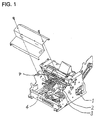
- FIG. 1 is a perspective view of a printer according to the invention to which either of the below described embodiments of a card transport mechanism can be applied.
- the printer shown in Fig. 1 is a type of a POS printer which can print receipt papers and journal papers.
- the printer is designed to be optionally equipped with the card transport mechanism described in detail below. If no card transport mechanism is provided the printer typically prints on roll paper whereas, when it is equipped with a card transport mechanism, the printer can be selectively controlled to print on card type printing media or the above mentioned roll paper.
- the mechanism of the printer other than the card transportation mechanism is almost the same as that of well known printers and, therefore, will not be described in detail here.
- the printer shown in Fig. 1 is of the type having a print head 2 mounted on a carriage 3 which is slidably supported to move print head 2 along a platen P to print on roll paper not shown in the drawing.
- the carriage is engaged with a drive belt of a drive belt set 4, the latter being driven by a motor 1 in response to an electrical signal.
- the direction of movement of the carriage and print head assembly is perpendicular to the direction in which the roll paper is transported.
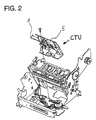
- Fig. 2 is a perspective view of the printer shown in Fig. 1 with some parts removed in order to show the position where a card transport unit CTU including the card transport mechanism of the first embodiment of the invention is installed in the printer.
- the card transport unit CTU comprises a card transport power transmission assembly, a card transport assembly, a card holder assembly, and a card transport position detector assembly.
- the card transport unit CTU has guide a frame 5 supporting the individual assemblies of the card transport mechanism.
- the guide frame 5 is substantially L-shaped in cross section with a first leg extending substantially horizontally in Fig. 2 and a second leg extending substantially vertically (actually, the two legs form an acute angle in accordance with the printer structure).
- the card transport unit CTU comprises a slider 8 extending substantially horizontally (in Fig. 2) and being slidably supported and guided by the guide frame 5 to be moveable up and down parallel to the second leg of guide frame 5.
- the card transport unit is positioned below print head 2 (omitted in Fig. 2) and is fastened by screws to the bottom of the main printer frame.
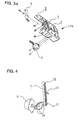
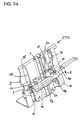
- Fig. 3a is a perspective view of the front side of the card transport unit
- Fig. 3b is a perspective view of its rear side
- Fig. 4 is used to describe the card transport power transmission assembly.
- Slider 8 constitutes the main part of the card transport assembly.
- the upper face of slider 8 forms a card stop 8e (Figs. 3a and 3b), against which the bottom edge of a card to be printed comes to rest when the card is inserted.
- a slider position detector 9 shown in Fig. 3a forms the card transport position detector assembly and in this embodiments is a light-transmitting sensor for detecting the position of slider 8.
- the card transport power transmission assembly in Fig. 4 employs a reversible stepping motor 6 for generating the card transport force. Rotation of its motor spindle is transferred by means of a gear train 10 to a belt drive pulley 11, the latter driving a transport belt 7 which is held by the drive pulley 11 and an idler pulley 12 as shown. Transport belt 7 extends in the direction of movement of slider 8 and has a drive pin 13 affixed to it to engage slider 8 in a manner described in more detail below.
- Fig. 5 is a perspective view of the card holder assembly of the card transport unit.
- the card holder assembly comprises a card holder lever 14 which is pivotally mounted to the slider 8.
- slider 8 has a substantially U-shaped cross section with the open end of the U facing downwardly.
- the main part of lever 14 extends in parallel to and partly in the slider 8.
- the two ends of lever 14 are bent to extend perpendicular to the intermediate main portion of the lever 14.
- the slider 8 has portions 8f extending in parallel to the bent end portions of lever 14.
- the end portions of lever 14 are pivotally supported by those portions 8f by means of pivots 14b.
- Torsion coil springs 15 (only the one on the right side is shown in Fig. 5) are employed to bias lever 14 in a clockwise direction in Fig.
- Rubber pieces 16 are provided on slider 8 as the fixed parts of card clamps
- rubber pieces 17 are provided on lever 14 as the moving parts of the card clamps .
- rubber pieces 17 are held by the bent end portions of lever 14 so as to oppose rubber pieces 16, respectively.
- the force clamping a card 100 between the rubber pieces (card clamps) 16 and 17 is determined by the spring force of springs 15.
- Reference numeral 18 in Fig. 5 denotes a first card detector which is a light-transmitting photo detector fixed to the main printer frame at the card removal/setting opening in order to detect when a card is inserted.
- Reference numeral 19 denotes a second card detector which is identical to card detector 18, and is optionally installed to the main printer frame below card detector 18.
- Fig. 5 also shows that in this embodiment drive pin 13 actually is engaged with lever 14 rather than directly with the slider 8.
- the point of contact between these two members is offset from the pivot axis of pivots 14b towards the rear side in Fig. 5.
- the driving force applied by drive pin 13 in the upward direction is transferred to the slider causing it to move.
- a driving force now applied by drive pin 13 will cause lever 14 to turn counterclockwise against the force of springs 15, thereby opening the card clamps 16/17.
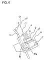
- Fig. 6 is a side view showing the card holder assembly when holding a card 100, i.e. with the card clamps 16/17 closed
- Fig. 7 is a side view showing the card holder assembly when waiting for insertion of a card 100, i.e. with the card clamps opened.
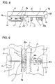
- Fig. 8 is an enlarged partial top view illustrating the means for holding the card transport mechanism to the guide frame
- Fig. 9 is a front view of Fig. 8.
- the leg of guide frame 5 to which slider 8 is mounted is provided with three cutouts 5f, 5g and 5h extending in parallel to the direction of movement of slider 8.
- Slider 8 is slidably mounted to guide frame 5 by means of U-shaped portions 8c engaging the inner edge 5fi of cutout 5f and an outer edge 5i of the guide frame 5, respectively, as shown in Fig. 8.
- Cutouts 5f and 5h are also used to provide space for the structures mounting lever 14 to slide 8.
- An engagement member 8g of slider 8 extends into the intermediate third cutout 5g.
- a slider guide lever 20 extends parallel and next to one of the opposing two edges of cutout 5g over a height corresponding to the stroke of slider 8.
- Lever 20 is pivotally supported by frame 5 with a pivot axis 20b extending in parallel to the leg of frame 5.
- a tension spring 21 is used for biasing lever 20 in the clockwise direction in Fig. 8, thereby pressing it against one of two opposite guide faces of engagement member 8g.
- the pressure exerted on engagement member 8g by lever 20 pushes its opposite second guide face 8d in engagement with the opposing edge 5c of cutout 5g.
- spring 21 By means of spring 21, the engagement member 8g of slider 8 is thus sandwiched, substantially without clearance, between two guide faces, namely 5c on the one side and 20a of lever 20 on the other side.
- guide faces namely guide face 5c of guide frame 5 and guide face 20a of lever 20 are mirror-finished to reduce the coefficient of friction and stabilize the card transport operation (the guide face 5c may either be formed by the edge of the cutout 5g itself or a piece of mirror-finished sheet metal laid over the edge and fixed to the guide frame 5).
- the two opposite guide faces of the engagement member 8g have a slightly inwardly curved shape as shown in Fig. 9 so that they contact guide faces 5c and 20a at only two points each (at top and bottom in the sliding direction) there being no contact in the center area.
- the distance between the contact points on each guide face is the largest possible, thus making slider 8 slide stably along the guide frame and preventing it from slanting.
- the pressure exerted by spring 21 is set so as to be sufficient to prevent slider 8 from slanting even if an external pressure is applied to the card during printing.
- Figs. 8 and 9 also show means for tensioning the transport belt 7.
- a tensioning member 22 is supported on the front side of guide frame 5 to be slidable in a direction perpendicular to the extension of transport belt 7 and at a position approximately in the middle of the belt loop length.
- Tensioning member 22 has a curved engagement portion 22b exerting pressure on the transport belt as shown in Fig. 9.
- the pressure is adjustable by means of a screw 22a arranged to move tensioning member 22 towards or away from transport belt 7.
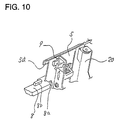
- Fig. 10 is a partial perspective view of the card transport unit.
- a reference position of slider 8 is detected by a slider position detector 9, a light-transmitting sensor.
- the slider 8 is detected when a detection tab 8a formed on slider 8 interrupts the light beam by entering the channel in slider position detector 9.
- Fig. 10 also shows the means for limiting the slider upward movement, namely an abutment member 8b on the slider cooperating with a stop portion 5a of the guide frame.
- Fig. 11 is a block diagram of the overall configuration of a printer including a card transport mechanism according to the first embodiment of the invention.
- block 71 represents the printer mechanism according to the present invention as described above.
- This printer mechanism comprises print head 2, motor 1, card transport motor 6, timing pulse generator 51 for controlling the print timing of print head 2, reset pulse generator 52 and reset pulse generator 53 for detecting the position of print head 2 and generating a corresponding reset signal, slider position detector 9, card detector 18 and card detector 19, each represented by a block of the same number within block 71.
- timing pulse generator 51 and reset pulse generators 52 and 53 are not shown elsewhere in the figures.
- FIG. 11 the elements outside block 71 form the control circuit for the printer mechanism of the present invention.
- a CPU 73 constitutes the heart of the control circuit and is connected to print head control circuit 81, motor 1 control circuit 82, and card transport motor control circuit 87, as well as to interface 72, ROM 74, and RAM 75.
- a print head control signal 76, a motor control signal 77, and a card transport motor control signal 78 are output from CPU 73 to circuits 81, 82 and 87, respectively.
- Each signal shaping circuit compares an analog input signal with a certain voltage level and outputs a digital signal. Therefore, comparators can be used as the signal shaping circuits.
- Shaping circuit 83 shapes the signal generated by timing pulse generator 51, and outputs a timing signal to CPU 73, which is used as a reference signal for controlling the power supply to print head 2.
- Shaping circuit 84 outputs a reset signal R to CPU 73, which is generated by reset pulse generator 52 when carriage 3 moves to one of two standby positions, the signal indicating that printing can be performed.
- Shaping circuit 85 outputs a reset signal J to CPU 73, which is generated by reset pulse generator 53 when carriage 3 moves to the other standby position, the signal also indicating that printing can be performed.
- reset pulse generators 52 or 53 is not described in detail here, but photo-interrupters mounted on both sides of the carriage moving path and respective interrupt plates fixed to the carriage can be used for these reset pulse generators.
- Shaping circuit 86 shapes the signals from slider position detector 9 to produce the slider position detection signal required to evaluate whether or not slider 8 is in its standby position (i.e., whether or not card insertion or setting is possible), and outputs it to CPU 73.
- Shaping circuit 88 shapes a signal from card detector 18 to output a card detection signal T to CPU 73, which is used to determine whether or not a card is present on the card holder assembly ( i.e. whether or not a card is set and whether or not a card is removed).
- Shaping circuit 89 shapes a signal obtained from card detector 19 to output card detection signal B to CPU 73, which is used for evaluating whether or not a card is inserted.
- the card transport mechanism of the first embodiment of the invention is described starting with the operation for reaching the state where card insertion is possible.
- the initialization operation described hereafter is first executed when the power is turned on. This process starts by CPU 73 determining, based on slider position detection signal, whether or not slider 8 is in its standby position.
- motor 6 (Fig. 4) is driven counterclockwise to move transport belt 7 such as to lower drive pin 13, thereby moving slider 8 and card holder lever 14 down to a position where slider 8 is no longer detected by the detector 9. This movement is caused due to engagement of engaging member 14a of card holder lever 14 with drive pin 13. This operation is omitted if slider 8 is not detected to be in its standby position when the power is turned on.
- card detector 18 detects the inserted card 100 and shaping circuit 88 (Fig. 11) outputs the card detection signal T to CPU 73, from which CPU 73 recognizes that the printer is ready for the card printing.
- CPU 73 thus outputs a motor control signal 78 to motor control circuit 87 to drive card transport motor 6 (Fig. 4) counterclockwise.
- card holder lever 14 is turned back by springs 15 to make rubber pieces 17 on card holder lever 14 press card 100 against rubber pieces 16.
- Card 100 is thus clamped by the card clamps 16/17 as shown in Fig. 6 and is thereby firmly held on the slider 8.
- the number of steps M specified here is the number of steps required to absorb the backlash of the power transmission system, i.e. gear train 10, which appears when the rotational direction of motor 6 is reversed. If card detector 19, which is optionally installed, is positioned at the lower position indicated in Fig. 5, card 100 will interrupt the light beam of card detector 19 as it is drawn into the printer. Shaping circuit 89 (Fig. 11) will therefore output the card detection signal B to CPU 73, enabling CPU 73 to confirm whether or not card 100 is still held by slider 8 and card holder lever 14.
- motor 6 (Fig. 4) is driven M steps clockwise to absorb the backlash of the power transmission system, and the current supply to motor 6 is maintained thereafter to hold the card transport mechanism as it is. Note that the looseness in transport belt 7 is reduced by the tensioning member 22 (Fig. 9) to reduce the backlash.
- printing is executed by means of print head control circuit 81 controlled by CPU 73 (Fig. 11).
- slider 8 and card 100 are advanced (lifted) to the next print position.
- one card advance step minimum line spacing
- N is designed to correspond to 1/N the vertical dot pitch of print head 2 (where N is a natural number) .
- the number N is determined taking the torque of the motor and the load into consideration. Multiple line printing can be executed by repeating the above sequence. Note also that printing to the bottom edge of card 100 is possible because the card stop of slider 8 can travel very near to print head 2.
- the card holding operation, card loading operation, card transport operation, and card release operation can be easily achieved using only the drive power of the card transport motor 6.
- the card transport mechanism can be structured as a card transport unit because the entire mechanism is mounted on the guide frame 5, thus enabling printers to be easily and optionally equipped with the card printing function.
- drive pin 13 of transport belt 7 engages card holder lever 14 such that when power supply to motor 6 is maintained after slider 8 is stopped in its uppermost position, drive pin 13 causes card holder lever 14 to turn to a position enabling card 100 insertion.
- the present invention is not limited to this embodiment.
- the mechanism and operation concerning the card holder lever can be modified in an alternative embodiment described hereafter.
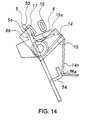
- Fig. 12 shows a partial perspective front view of the alternative embodiment.
- a lever drive projection 5d is formed on guide frame 5 to push card holder lever 14 to rotate on pivots 14b as card holder lever passes the projection 5d.
- Figs. 13 and 14 are schematic side sectional views along line A-A in Fig. 12 illustrating the card clamp opening operation executed by using the above explained mechanism. In the state shown in Fig. 13, springs 15 bias card holder lever 14 clockwise to press rubber pieces 17 against rubber pieces 16, and card 100 is clamped.
- card holder lever 14 does not receive any force tending to move it up or down along guide frame 5 because it is no longer the inclined portion 14c that abuts on a corner of the projection 5d but the lower end or corner 14d of portion 14c abuts on a portion of projection 5d which is parallel to the guide frame 5.
- a holding current need not be applied to motor 6 in order to hold the standby state for setting or removing cards, thereby the power consumption and the heat generation can be reduced.
- Fig. 12 shows another alternative to the structure explained above in that the main part of lever 14 extends below the bottom of slider 8 rather than at least partly entering an inverted U-shape of the slider. Furthermore, Fig. 12 shows in more detail the manner in which lever 14 is pivotally mounted to slide 8 and the bias force is applied by spring 15.
- a second embodiment of a printer according to the present invention is described below with reference to Figs. 15 to 29 and Fig. 1. As will be explained, the second embodiment does not require a separate card transport motor since the card transport mechanism is driven by the motor 1 of the printer.
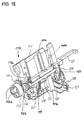
- Fig. 15 is a perspective view of a card transport unit CTU forming the card transport mechanism according to the second embodiment of the invention, and its position in the printer.
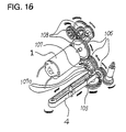
- Fig. 16 is a perspective drawing of the means for transferring the drive power of motor 1 in the second embodiment to carriage drive belt set 4.
- Fig. 17 is an external perspective view of the card transport mechanism, and
- Fig. 18 is an external perspective view from the back of the card transport mechanism.
- Motor 1 rotates a carriage drive pulley 105 by means of a head transport gear train 106 and the motor gear attached to the motor 1 shaft (not shown in the figures) to drive carriage drive belt set 4.
- Motor 1 also drives a paper transport gear train 108, which selectively transfers the motor torque to the roll paper transport mechanism (not shown in the figures) used to feed roll paper for printing.
- Head transport transfer gear 107 is one of the gears forming head transport gear train 106 and it comprises three tabs 107a which are angularly displaced from each other and project in the axial direction. Head transport transfer gear 107 serves to transfer drive power to the card transport mechanism. In the present embodiment a single motor is used as the drive source for a plurality of power driven functions in the printer.
- Respective clutches are provided (which are neither shown nor described in more detail) for the individual functions except for the print head carriage drive. While the motor is running, the print head carriage continues to be reciprocated. All clutches are disengaged while the print head carriage is moving within the region of its stroke where printing is possible, i.e. where the print head is opposite to a printing medium (roll paper for receipt printing, roll paper for journal printing or card type print medium). When the print head carriage is moving outside of the area where printing is possible, at least one of the clutches corresponding to a desired or necessary function is engaged.
- the card transport unit of the second embodiment comprises a guide frame 111 to which the individual components or mechanisms are mounted, and which in turn is adapted to be mounted to the main printer frame.
- a slider 121 corresponding to and serving the same purpose as slider 8 of the first embodiment is slidably supported by the guide frame 111.
- the means for supporting and guiding the slider 121 are similar to though simpler than those used in the first embodiment, namely U-shaped portions of the slider embrace respective guide edges of the guide frame, and an engagement member of the slider engages a guide groove 111a (Fig. 18) of the guide frame 111 for lateral guidance.
- the slider is provided with a card holder lever 131 pivotally supported to be moved between a closed position for clamping a card and an opened position for insertion or removal of a card.
- Reference numerals 118a and 118b in Fig. 18 denote card guides composed of flexible members like a leaf spring fixed to guide frame 111. They are used to guide the card to be printed to the desired position on the slide 121.
- the card transport unit CTU comprises a card transport power transmission assembly, a card transport assembly, a card holder assembly, and a card holder lever position detector assembly.
- Guide frame 111 supports the card transport power transmission assembly, card transport assembly, card holder assembly, and card holder lever position detector assembly.
- a card transport power transmission gear means 112 has three holes 112a (Figs. 15 and 18) formed on its outer side for engaging the three tabs 107a of head transport transfer gear 107, and a gear 112b on the other side.
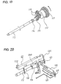
- Fig. 19 shows just the power transmission mechanism (seen from the front) connected to the card transport mechanism according to the second embodiment of the invention.
- a slider drive shaft 113 is driven by the gear 107 engaging gear means 112, and the shaft in turn transfers power to the card transport mechanism.
- a card transport transfer gear 115 rotatably supported on shaft 113 is coupled to gear 112b via a speed reducing gear train 116.
- a spring 114 is wound around shaft 113 to form a spring clutch; one end of the spring 114 is bent up to a raised position in order to engage a hole formed in gear 115, and the spring clutch is adjusted to slip when an over-load is applied to the drive system downstream from slider drive shaft 113.
- Fig. 20 is a partial front view of the card transport mechanism, and is used to describe how the slider is driven.
- Fig. 21 is a detailed exploded view of a clutch mechanism of Fig. 20.
- Fig. 22 is used to describe the mechanism of a rack 1211 provided on the slider and a slider drive gear 124 disposed on slider drive shaft 113.
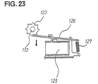
- Fig. 23 is used to describe the trigger mechanism for card transport selection.
- Slider 121 is mounted and moves parallel to the molded plastic guide frame 111, as mentioned above, and comprises a card stop 121d on which the bottom edge of card 100 stops (similar to the previous embodiment the card stop is formed by the upper side of slider 121).
- Slider 121 further comprises the rack 1211 whose uppermost tooth 121a (Figs. 21 and 22) is laterally offset from the other teeth 121b.It is to be noted that in the lateral direction in Fig. 18, the rack 1211 is provided at the position of the guide groove 111a and extends parallel to the latter.
- the reference numeral 111b denotes a U-shaped cover integrally formed with guide frame 111. In the lowermost position of the slide 121, as shown in Fig. 18, the rack 1211 is fully inserted into cover 111b which provides an additional guide to the slide 121. The open rear side of the cover exposes the rack to the slider drive gear 124 described in more detail below.
- Spring 122 shown in Fig. 21 forms a spring clutch and is press fitted onto shaft 113. Both ends of the spring 122 are bent out to raise from shaft 113.
- a ratchet wheel 123 is rotatably mounted on shaft 113. The ratchet teeth of the ratchet wheel 123 are uniformly distributed around the outer circumference of the ratchet wheel. The ratchet wheel 123 engages one of the raised ends of clutch spring 122.
- Slider drive gear 124 is also rotatably mounted on shaft 113 and engaged with the other raised end of spring 122.
- Gear 124 comprises on its outer circumference a tooth 124a for meshing with the top tooth 121a on the rack 1211, teeth 124c for meshing with the other teeth 121b, and a trapezoidal cam 124b shown in Figs. 25 and 26.
- the trigger mechanism for card transport selection comprises an electromagnet 125, a trigger plate 126 and a spring 127.
- One end of trigger plate 126 is biased by the spring 127 (a tension coil spring in this embodiment) to engage the claws of ratchet wheel 123 with the other end.
- Trigger plate 126 is so positioned that said engagement can be released by supplying current to the electromagnet 125 which then attracts the trigger plate.
- Slider return spring 128 (Figs. 17 and 18) is connected to guide frame 111 at one end and to slider 121 at the other end in order to bias slider 121 into its downward standby position.
- Slider return spring 129 performs the same function as slider return spring 128. Slider 121 can thus move smoothly on guide frame 111 because slider return spring 128 and slider return spring 129 are positioned balanced on right and left sides.
- Reference numerals 117 in Fig. 18 denote shock dampers employed for damping the shock (and the noise associated with it) when the slider is returned by the return springs from its uppermost position to its lowermost position.
- slider return spring 128 is tensioned to apply a force fa at a distance L1 to the center point O of a possible rocking movement and slider return spring B 129 is tensioned to apply a force fb at a distance L2, both against the force F acting on that point O of slider 121 when slider drive gear 124 works to move slider 121 up.
- Figs. 25 and 26 are used to describe the card holder assembly and the card holder lever position detector assembly.
- Fig. 25 is a side view showing the state where the card holder assembly according to the present embodiment holds a card clamped and the card holder lever is not detected to be in its standby position
- Fig. 26 shows the state where the card holder assembly is opened and card insertion enabled and the card holder lever is detected by detector 141 to be in its standby position.
- Card holder lever 131 is pivotally mounted on slider 121 in substantially the same way as described with respect to lever 14 in the first embodiment.
- Rubber pieces 133 function as moveable clamp members, and are provided on card holder lever 131 so as to hold a card 100 in cooperation with fixed clamp members 121c (that may also comprise or be surrounded by rubber pieces) formed on the right and the left side of slider 121 opposite to a respective rubber piece 133.
- the moveable and the fixed clamp members thus form card clamps similar to the first embodiment.
- Card holder lever 131 further comprises an arm 131a, which is positioned to contact with the trapezoidal cam 124b of slider drive gear 124, and a detection lever 131c which operates position detector 141.
- a card clamp spring 132 (preferably there is one on each side) is a torsion coil spring used for biasing the lever 131 relative to the slider 121 and, thus, for applying the pressure for clamping a card 100.
- Detector 141 is a mechanical switch fixed to guide frame 111 and comprises a lever 141a for engaging with detection lever 131c of card holder lever 131. Detector 141 outputs a LOW level signal when lever 141a is turned clockwise as seen in the figures (against a bias force) ; when lever 141a is not driven to the right, but turned to the left by its bias force, the detector 141 outputs a HIGH level signal. Note that detector 141 may alternatively be a photo detector positioned such that the light beam thereof is interrupted by lever 131 to enable position detection.
- Card detector 18 is an optional light-transmitting photo detector provided at the card 100 insertion opening for out-putting a signal when a card is inserted.
- Card detector 19 is provided near the card stop of slider 121 when the latter is in its lowermost position, and performs the same function as card detector 18.
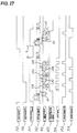
- Fig. 27 is a timing chart of the card printing timing and card transport timing in this second embodiment of the invention.
- Motor drive signal 151 is used to control driving motor 1.
- Timing signal 152 is the shaped output signal generated by timing pulse generator 51 (not shown in the figures) in sync with motor 1 rotation used to determine the drive timing of print head 2.
- Reset signal R (153) is the shaped output signal generated by reset pulse generator 52 (not shown in the figures) which is a photo detector provided at the receipt paper side of the main frame for outputting a signal when carriage 3 reaches the home position on the receipt side.
- Reset signal J is the shaped output signal generated by reset pulse generator 53 (not shown in the figures) which is a photo detector provided at the journal paper side of the main frame for outputting a signal when carriage 3 reaches the home position on the journal side.
- Print area signal 154 indicates the timing during which printing is possible.
- Card transport signal 155 is used to drive the electromagnet 125 (Fig. 23) in the trigger assembly for selectively performing the card transport.
- Card holder lever position detector signal 157 is output by position detector 141 as a LOW level signal in the state where the card holder lever standby position is detected (card insertion enabled state).
- Card detection signal B is the output signal generated by card detector 19 (Fig. 26), which outputs card detection signal B (156) with a HIGH level when no card is loaded in the printer, and outputs a LOW level signal when a card is loaded in the printer.
- Card detection signal T is the output signal of card detector 18 (Fig. 26), which outputs a HIGH level signal when no card is loaded and outputs a LOW level signal when a card is loaded in the printer; this operation is the same as that of card detector 19.
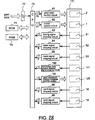
- Fig. 28 is a block diagram of the overall configuration of a printer using the card transport mechanism according to the second embodiment of the invention.
- Fig. 28 is similar to Fig. 11 of the first embodiment and so it may suffice to describe the differences only.
- the printer mechanism has the position detector 141 and the electromagnet 125, respectively.
- 180 is the signal shaping circuit for shaping the signal output by detector 141 and 181 is the control circuit for controlling the electromagnet 125 in response to a signal from CPU 73.
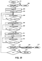
- Fig. 29 is a flow chart of the operation for initializing the card transport mechanism of the second embodiment to enable card insertion. The initializing sequence is described later in detail.
- the slider 121 In the standby state, i.e. the state where the card transport mechanism is ready for a card to be inserted, the slider 121 is in its lowermost position and the card holder lever 131 is turned to keep the card clamps opened as shown in Fig. 26. After a card has been inserted, the slider 121 is lifted stepwise while printing is performed line by line. When the slider has reached its uppermost position and the last line has been printed, the arrangement is kept in this state waiting for the card to be removed. After removal of the card - or a after predetermined waiting time - the slider is returned to its lowermost position by means of its return springs to reach a state shown in Fig. 25. The individual steps of this operation will be described in detail below starting from the standby state shown in Fig. 26.
- card 100 When a card 100 is inserted along guide frame 111 and card guides 118a, 118b, card 100 is led to a position between fixed clamp members 121c and arm 131b of card holder lever 131 with its moveable clamp members 133.
- the side edge of card 100 thus blocks the light beam of card detector 19, which is located near the lower standby position of slider 121 in the card 100 insertion path.
- card detection signal B (Fig. 27) output from card detector 19 to change to a LOW level signal.
- Card detection signal T (158) changes similarly.
- Card detection signal B is input through shaping circuit 89 (Fig. 28) to CPU 73, causing CPU 73 to output a motor drive signal 151 (Fig. 27) with HIGH level through motor control circuit 82 to drive motor 1.
- motor 1 begins to turn, driving head transport gear train 106 and paper transport gear train 108 (Fig. 16), and head transport transfer gear 107, card transport power transmission gear means 112, card transport power transmission gear train 116, card transport transfer gear 115, and slider drive shaft 113 (Fig. 19) in the directions of the respective arrows.
- timing signal 152 is applied from CPU 73 (Fig. 28) through card transport electromagnet control circuit 181 to card transport electromagnet 125 for only a period T1 (LOW level period indicated as CH) of card transport signal 155 (Fig. 28)).
- the trigger plate 126 is therefore pulled in the direction of the arrow, overcoming the tension of coil spring 127, by electromagnet 125 (Fig. 23), releasing engagement with ratchet wheel 123, and enabling ratchet wheel 123 to turn with shaft 113.
- Clutch spring 122 therefore tightens against shaft 113, and slider drive gear 124 turns together with shaft 113. Because current is applied to the electromagnet 125 only during period T1, trigger plate 126 is returned again by spring 127 when the current supply to the electromagnet 125 is stopped, thus causing trigger plate 126 to engage the next claw of the ratchet wheel 123 thereby prohibiting ratchet wheel 123 to rotate beyond the next claw.
- the cam 124b of slider drive gear 124 (Fig. 26) therefore turns in the direction of the arrow and disengages from arm 131a of card holder lever 131.
- card clamp springs 132 turn card holder lever 131 clockwise thereby closing the card clamps (133, 121c) to clamp the card.
- lever 141a of detector 141 and detection lever 131c of card holder lever 131 separate, card holder lever position detector signal 157 (Fig. 27) becomes HIGH, and the card is held firmly to enable printing.
- reset signal R (153) or reset signal J (159) (Fig. 27) output from reset pulse generator 52 or reset pulse generator 53 (not shown in the figures), respectively, are obtained for confirmation of the carriage 3 home position.
- CPU 73 outputs the print command to print head control circuit 81 while print area signal 154, which indicates printing to the present print line is possible, is active to execute printing. Note that print area signal 154 is made by a logic circuit in sync with the reset signals.
- the present embodiment is shown in a six line printer configuration.
- the number of printable lines is determined by the line spacing.
- the print/card transport operation described above is repeated five times for periods CF1 to CF5 to print six lines.
- card 100 When the last line has been printed, card 100 has been advanced to the top position and motor drive signal 151 assumes a stop state.
- the corresponding stop period T2 of the signal's stop state should be set long enough to allow removal of the card. If card detector 18, which is an optional detector, is provided, removal of the card can be detected by a HIGH level of card detection signal T (158). This would avoid the necessity of presetting a stop period, since in such case the stop period would automatically be ended based on card detection signal T.
- the slider 121 is kept in its uppermost position after the last line has been printed to wait for card removal.
- the card clamp assembly is still in its closed condition, different from the first embodiment. Therefore, the clamping force holding the card to the slider should be strong enough to securely hold the card during transport and printing and yet to allow it to be withdrawn without any danger of damage to the card.
- the above described embodiment could easily be modified to allow the card clamp assembly to be opened in the uppermost position of the slider in a manner similar to that of the embodiment explained with respect to Fig. 12.
- TC in steps 205, 207, 210, and 214 indicates the current count value of a timing signal counter which is a type of free running counter in the present embodiment
- T3 and T1 in Fig. 29 correspond to the periods T3 and T1 indicated in Fig. 27, respectively, expressed in the form of the number of pulses of the timing signal 152 to be counted during the respective period
- N in step 218 is the number of card transport operation cycles minus 1.
- the card transport mechanism is cyclically operating, if the total number of possible states of the card transport mechanism within one cycle is N+1, starting from the state the card transport mechanism has when power supply to the printer is switched on, the state will have to be changed N times to bring the card transport mechanism into each of the possible states once. Thus, depending on which state the mechanism has when power supply is switched on, the maximum number of times the state of the mechanism has to be changed in order to reach the standby state is N.
- a LOW card holder lever position detector signal state is checked (step 202). If the detector signal is LOW, card setting is enabled, and the printer enters the standby state (step 203) waiting until a card is inserted.
- step 207 returns YES
- the card transport signal is set ON (step 208) (note that ON corresponds to LOW level in Fig. 27), and current is supplied for period T1 only (steps 209, 210, 211).
- Card holder lever position detector signal state is again checked (step 215) whether LOW or not. If step 215 returns YES, card setting is possible.
- card holding and transport and printer standby states can be easily achieved with a single low-cost trigger assembly using the power of a motor driving both the paper transport and carriage drive assemblies.
- a unitized card transport mechanism enabling simple installation and removal from the printer assembly can thus be achieved.
- the card By providing a slider comprising a card stop against which the bottom edge of the printer card rests and a holding means for holding the card to the slider, a guide frame comprising at least one guide member engaging and guiding the slider parallel to the guide frame, and a drive means for moving the slider with the card along the guide member relative to the printing means, the card can be simply held between clamping members and advanced by moving the slider on which it is held. It is therefore possible to reliably advance multiple layer card forms.
- Power consumption is also reduced, making it possible to use a smaller power supply and improving the energy efficiency of the printer.
- the card transport mechanism comprises a slider on a guide frame and a means for driving the slider
- the card transport mechanism can be manufactured as a single unit that can be used to help greatly reduce printer assembly costs. Because this unit can also be assembled into the printer as an option during final printer assembly, printer design specifications can be easily changed. Control is also extremely simple because the card can be driven merely by applying a signal to a single means as when controlling a stepping motor or trigger magnet to move the slider.
- the present invention thus provides significant practical benefits.
Abstract
Description
- The present invention relates to a card transport mechanism for a printer allowing the printer to perform validation printing of plural lines on card type print media (simply referred to as card in the following) or copying paper used, for example, in point-of-sale (POS) systems and electronic cash registers (ECR). The present invention further relates to a printer including such mechanism.
- In the prior art, such validation printing is typically performed by means of a printer like the one schematically shown in Fig. 1, as an example, which has a card feed mechanism mounted therein.
- Fig. 30 is a simplified side view of a first prior art example of such card feed mechanism. In this card feed mechanism a
card transport roller 301 is driven by acard transport motor 6 via agear train 10 to be rotated by the motor. Acard presser roller 304 is positioned opposite to theroller 301 and rotatably mounted at one end of alever 303 which is pivotally supported at an intermediate portion (at 303a) by a frame not shown. The other end oflever 303 is coupled to an actuatingrod 302a of aplunger 302. Abiasing spring 305 is stretched between thelever 303 and a part (not shown) fixed relative to the frame.Spring 305 biases lever 303 in a clockwise direction. In this construction, whenplunger 302 is deenergized,spring 305draws lever 303 androller 304 into a position shown in dotted lines in Fig. 30. As will be appreciated, in thisposition roller 304 is separated fromroller 301. By energizingplunger 302lever 303 is turned counterclockwise against the force ofspring 305 into the position shown in solid lines in Fig. 30, whereroller 304 is pressed againstroller 301. - A
card 100 to be printed is inserted from the top through the gap between aprint head 2 and aplaten 25, and then betweencard transport roller 301 androller 304 until its lower edge comes to rest on a card stop 306. Thus thecard 100 is set into the printer. - When current is supplied to
plunger 302 aftercard 100 has been inserted,lever 303 will be turned as mentioned before, thereby causingroller 304 to move to the position indicated by solid lines.Card 100 is thus pinched betweentransport roller 301 andpresser roller 304. Then themotor 6 is driven totransport card 100 to a specified position utilizing the friction between the rollers and the card and, when the specified position has been reached, printing of a first line is performed. - After the first line has been printed,
motor 6 is again driven tofurther lift card 100 to the next print position, and then the next line is printed. This cycle is repeated until the last line has been printed. When printing is finished, the current supply toplunger 302 is interrupted, thus allowingspring 305 to returnlever 303 androller 304 to the standby position (dotted line in Fig. 30).Card 100 can now be removed, and the card printing operation is completed. - A simplified side view of a second prior art example of a card feed mechanism is shown in Fig. 31. Note that Fig. 31 only shows the feed mechanism while the print mechanism is omitted. In this prior art, a
card transport roller 323 is connected via atiming belt 325 to aratchet wheel 327.Ratchet wheel 327 is intermittently driven by means of aclaw 328, as will be explained in more detail below. Acard presser roller 322 is rotatably supported by aholder 320 mounted to be slidable between a standby position shown in solid lines and an operative position shown in dot-dot-dash lines. A spring 319 is employed tobias holder 320 into the standby position, while aplunger 321 is provided to moveholder 320 androller 322 into the operative position in whichroller 322 is opposite toroller 323 and pressed against it. - When current is supplied to plunger 321 after a
card 100 has been inserted from the top,roller 322 is moved in the direction of the arrow from the standby position to the operative position.Card 100 is thus pinched betweentransport roller 323 andpresser roller 322. In response to the intermittent rotation ofratchet wheel 327 thecard 100 is then transported to a specified position utilizing the friction between the two rollers and the card.- - The intermittent feed
technique using claw 328 will be briefly described only. Atransport lever 329 is pivotally supported for an oscillating movement around anaxis 329b and driven at a specified timing by cooperation between a cam (not shown) and atension spring 332. A cardtransport trigger lever 331 is pivotally supported at 331a. Lever 331 has a projection 331b engaging a notch 329a oflever 329 during standby, thereby preventinglever 329 from turning in the direction indicated by arrow z. When a paper feed command is received, current is supplied to anelectromagnet 330, which pullslever 331 in the direction of arrow y thereby drawing its projection 331b out of notch 329a. Under the control of the cam (not shown) andspring 332card transport lever 329 is then turned in the direction of arrow z. Theclaw 328 is pivotally supported at an end oflever 329 and biased by a spring to engageratchet wheel 327. Upon rotation oflever 329claw 328 drives theratchet wheel 327 by one step.Lever 329 is then rotated in the direction of arrow x by the cam, and projection 331b oflever 331 drops into the notch 329a again, thereby lockinglever 329 and completing one card transport cycle. - The following problems exist with the prior art described above.
- (1) When multiple-layer printing forms are used as card, the top and bottom layers often slip relative to one another as the form is transported because the friction between the card and the rollers is larger than the friction between the layers of the form, thus making it very difficult or impossible to print to the specified printing position throughout the layers.
- (2) It is impossible to eliminate a non-printable top or bottom margin of the printing form or card that is a little wider than the radius of the card transport roller if the card transport roller is provided below or above the print head. Though the problem can be solved by a structure which has two card transport means both below and above the print head, such structure is not suitable for this type of printers because of its large size and high cost.
- (3) Reducing overall printer assembly size is difficult because a large power supply is required to supply sufficient electrical power for exerting sufficient pressure on the presser roller to hold the card without slippage between the card and the rollers when the card is pulled by hand or other external force.
- (4) Because printing forms or cards must be inserted to the card stop manually, it is very difficult to handle or print the cards or forms if the depth of the card stop is larger than the length of the cards or forms.
- (5) The control circuit is made more complex and the total cost rises because it is necessary to control both the means for transporting the card and the means for pressing the card to the card transport roller.
- (6) It is not possible to build a combined card transport and presser unit because the card transport mechanism and the card presser mechanism are separated by the card. This increases the number of final assembly steps and unit cost.
- Therefore, the object of the present invention is to overcome the problems of the prior art explained above and to provide a highly reliable, durable card transport mechanism that is free of changes in the card transport pitch, allows the printer to print to cards that are small enough to enter all the way into the printer, and is structured as a unit which can be optionally mounted to a printer. Another object of the invention is to provide a printer including such card transport mechanism.
- These objects are achieved with a card transport mechanism as claimed in
claim 1 and a printer as claimed inclaim 11, respectively. Preferred embodiments of the invention are subject-matter of the dependent claims. - In a card transport mechanism according to the present invention, the card to be printed is held on a slider that travels along a guide frame, thus causing the print medium, i.e. the card to move relative to the print means while being held on the slider. For holding the card to the slider a rotatably supported card holder lever may be used to selectively apply pressure to the card depending on the position of the slider, i.e., there are two states: one where the card holder lever is turned to a position allowing a card to be set or removed, and another one where the card holder lever is in the position to apply pressure to hold the card. The card can thus be moved while being held, and released for setting or removing by simply controlling the position of the slider.
- Preferred embodiments of the invention and further objects and advantages of the invention will be explained in detail below with reference to the drawings, in which:
- Fig. 1
- is a perspective view of a printer according to the invention,
- Fig. 2
- is a perspective view showing where a card transport unit according to a first embodiment of the invention is installed to the printer,
- Fig. 3a
- is a perspective front view of the card transport unit,
- Fig. 3b
- is a perspective rear view of the card transport unit,
- Fig. 4
- schematically illustrates the card transport power transmission assembly,
- Fig. 5
- is a perspective view of the card transport and the card holder assemblies of the card transport unit,
- Fig. 6
- is a side view showing the card holder assembly in the state of holding a card,
- Fig. 7
- is a side view showing the card holder assembly in the state allowing a card to be inserted,
- Fig. 8
- is an enlarged partial top view of the means holding the card transport mechanism to the guide frame,
- Fig. 9
- is a front view of Fig. 8,
- Fig. 10
- is a partial perspective view illustrating position detection means for detecting the position of the card transport mechanism of the first embodiment,
- Fig. 11
- is a block diagram of the overall configuration of a printer according to the first embodiment of the invention,
- Fig. 12
- is an enlarged partial perspective view illustrating a modification of the first embodiment of the invention,
- Fig. 13 and 14
- are views, similar to Figs. 6 and 7, respectively, of the modified embodiment,
- Fig. 15
- is a perspective view of a card transport unit according to a second embodiment of the invention and its position in the printer,
- Fig. 16
- is a perspective view illustrating means for transferring the drive power of the printer motor to a carriage drive belt set according to the second embodiment of the invention,
- Fig. 17
- is a perspective front view of the card transport unit according to the second embodiment,
- Fig. 18
- is a perspective rear view of the card transport unit of the second embodiment,
- Fig. 19
- is a perspective view of the power transmission mechanism for the card transport mechanism according to the second embodiment of the invention,
- Fig. 20
- is a perspective front view schematically illustrating the card transport assembly of the second embodiment,
- Fig. 21
- is a front view of the clutch mechanism of the slider drive shaft in the second embodiment,
- Fig. 22
- is used to describe the rack and gear mechanism of the second embodiment,
- Fig. 23
- is used to describe the trigger mechanism for card transport selection in the second embodiment,
- Fig. 24
- illustrates the relationship between the forces acting on the slider in the second embodiment,
- Fig. 25
- is a side view of the card holder assembly according to the second embodiment in the state of holding a card in the card holder lever undetected position,
- Fig. 26
- is a side view of the card holder assembly in the state where card insertion is enabled in the card holder lever detected position,
- Fig. 27
- is a timing chart of the card printing and card transport timing according to the second embodiment of the invention,
- Fig. 28
- is a block diagram of the overall configuration of a printer according to the second embodiment of the invention,
- Fig. 29
- is a flow chart of the operation for initializing the card transport mechanism of the invention to enable card insertion,
- Fig. 30
- is a side view of the card feed mechanism according to a first prior art example, and
- Fig. 31
- is a side view of the card feed mechanism according to a second prior art example.
- A first embodiment of a printer according to the present invention is described below with reference to Figs. 1 to 11. Fig. 1 is a perspective view of a printer according to the invention to which either of the below described embodiments of a card transport mechanism can be applied.
- The printer shown in Fig. 1 is a type of a POS printer which can print receipt papers and journal papers. The printer is designed to be optionally equipped with the card transport mechanism described in detail below. If no card transport mechanism is provided the printer typically prints on roll paper whereas, when it is equipped with a card transport mechanism, the printer can be selectively controlled to print on card type printing media or the above mentioned roll paper. The mechanism of the printer other than the card transportation mechanism is almost the same as that of well known printers and, therefore, will not be described in detail here.
- The printer shown in Fig. 1 is of the type having a
print head 2 mounted on acarriage 3 which is slidably supported to moveprint head 2 along a platen P to print on roll paper not shown in the drawing. The carriage is engaged with a drive belt of a drive belt set 4, the latter being driven by amotor 1 in response to an electrical signal. The direction of movement of the carriage and print head assembly is perpendicular to the direction in which the roll paper is transported. - Fig. 2 is a perspective view of the printer shown in Fig. 1 with some parts removed in order to show the position where a card transport unit CTU including the card transport mechanism of the first embodiment of the invention is installed in the printer. The card transport unit CTU comprises a card transport power transmission assembly, a card transport assembly, a card holder assembly, and a card transport position detector assembly. The card transport unit CTU has guide a
frame 5 supporting the individual assemblies of the card transport mechanism. In this embodiment, theguide frame 5 is substantially L-shaped in cross section with a first leg extending substantially horizontally in Fig. 2 and a second leg extending substantially vertically (actually, the two legs form an acute angle in accordance with the printer structure). As will be explained in more detail below, the card transport unit CTU comprises aslider 8 extending substantially horizontally (in Fig. 2) and being slidably supported and guided by theguide frame 5 to be moveable up and down parallel to the second leg ofguide frame 5. The card transport unit is positioned below print head 2 (omitted in Fig. 2) and is fastened by screws to the bottom of the main printer frame. - Fig. 3a is a perspective view of the front side of the card transport unit, Fig. 3b is a perspective view of its rear side and Fig. 4 is used to describe the card transport power transmission assembly.
-
Slider 8 constitutes the main part of the card transport assembly. The upper face ofslider 8 forms acard stop 8e (Figs. 3a and 3b), against which the bottom edge of a card to be printed comes to rest when the card is inserted. Aslider position detector 9 shown in Fig. 3a forms the card transport position detector assembly and in this embodiments is a light-transmitting sensor for detecting the position ofslider 8. - The card transport power transmission assembly in Fig. 4 employs a
reversible stepping motor 6 for generating the card transport force. Rotation of its motor spindle is transferred by means of agear train 10 to abelt drive pulley 11, the latter driving atransport belt 7 which is held by thedrive pulley 11 and anidler pulley 12 as shown.Transport belt 7 extends in the direction of movement ofslider 8 and has adrive pin 13 affixed to it to engageslider 8 in a manner described in more detail below. - Fig. 5 is a perspective view of the card holder assembly of the card transport unit. The card holder assembly comprises a
card holder lever 14 which is pivotally mounted to theslider 8. In this embodiment,slider 8 has a substantially U-shaped cross section with the open end of the U facing downwardly. The main part oflever 14 extends in parallel to and partly in theslider 8. The two ends oflever 14 are bent to extend perpendicular to the intermediate main portion of thelever 14. Theslider 8 hasportions 8f extending in parallel to the bent end portions oflever 14. The end portions oflever 14 are pivotally supported by thoseportions 8f by means ofpivots 14b. Torsion coil springs 15 (only the one on the right side is shown in Fig. 5) are employed to biaslever 14 in a clockwise direction in Fig. 5 with respect toslider 8.Rubber pieces 16 are provided onslider 8 as the fixed parts of card clamps , andrubber pieces 17 are provided onlever 14 as the moving parts of the card clamps . As shown in Fig. 5,rubber pieces 17 are held by the bent end portions oflever 14 so as to opposerubber pieces 16, respectively. As will be appreciated, the force clamping acard 100 between the rubber pieces (card clamps) 16 and 17 is determined by the spring force ofsprings 15. -
Reference numeral 18 in Fig. 5 denotes a first card detector which is a light-transmitting photo detector fixed to the main printer frame at the card removal/setting opening in order to detect when a card is inserted.Reference numeral 19 denotes a second card detector which is identical tocard detector 18, and is optionally installed to the main printer frame belowcard detector 18. - Fig. 5 also shows that in this
embodiment drive pin 13 actually is engaged withlever 14 rather than directly with theslider 8. The point of contact between these two members is offset from the pivot axis ofpivots 14b towards the rear side in Fig. 5. As a result, as long as the slider's sliding movement is not hindered, i.e., as long as the slider has not reached its uppermost position, the driving force applied bydrive pin 13 in the upward direction is transferred to the slider causing it to move. When the slider has reached its uppermost position and is prevented from sliding any further (as will be described in more detail below) a driving force now applied bydrive pin 13 will causelever 14 to turn counterclockwise against the force ofsprings 15, thereby opening the card clamps 16/17. - Fig. 6 is a side view showing the card holder assembly when holding a
card 100, i.e. with the card clamps 16/17 closed, and Fig. 7 is a side view showing the card holder assembly when waiting for insertion of acard 100, i.e. with the card clamps opened. - Fig. 8 is an enlarged partial top view illustrating the means for holding the card transport mechanism to the guide frame, and Fig. 9 is a front view of Fig. 8.
- As is best shown in Fig. 3b, the leg of
guide frame 5 to whichslider 8 is mounted is provided with threecutouts slider 8.Slider 8 is slidably mounted to guideframe 5 by means ofU-shaped portions 8c engaging the inner edge 5fi ofcutout 5f and anouter edge 5i of theguide frame 5, respectively, as shown in Fig. 8.Cutouts 5f and 5h are also used to provide space for thestructures mounting lever 14 to slide 8. An engagement member 8g ofslider 8 extends into the intermediatethird cutout 5g. Aslider guide lever 20 extends parallel and next to one of the opposing two edges ofcutout 5g over a height corresponding to the stroke ofslider 8.Lever 20 is pivotally supported byframe 5 with a pivot axis 20b extending in parallel to the leg offrame 5. Atension spring 21 is used for biasinglever 20 in the clockwise direction in Fig. 8, thereby pressing it against one of two opposite guide faces of engagement member 8g. The pressure exerted on engagement member 8g bylever 20 pushes its oppositesecond guide face 8d in engagement with the opposingedge 5c ofcutout 5g. By means ofspring 21, the engagement member 8g ofslider 8 is thus sandwiched, substantially without clearance, between two guide faces, namely 5c on the one side and 20a oflever 20 on the other side. This ensures an exact parallel guidance ofslider 8 over the full length of its stroke, keeping it approximately perpendicular to the direction of card transport and avoiding any rocking or slanting movement of the slider. Note that the guide faces, namely guideface 5c ofguide frame 5 and guideface 20a oflever 20 are mirror-finished to reduce the coefficient of friction and stabilize the card transport operation (theguide face 5c may either be formed by the edge of thecutout 5g itself or a piece of mirror-finished sheet metal laid over the edge and fixed to the guide frame 5). - The two opposite guide faces of the engagement member 8g have a slightly inwardly curved shape as shown in Fig. 9 so that they contact guide faces 5c and 20a at only two points each (at top and bottom in the sliding direction) there being no contact in the center area. The distance between the contact points on each guide face is the largest possible, thus making
slider 8 slide stably along the guide frame and preventing it from slanting. The pressure exerted byspring 21 is set so as to be sufficient to preventslider 8 from slanting even if an external pressure is applied to the card during printing. - Figs. 8 and 9 also show means for tensioning the
transport belt 7. To this end, a tensioningmember 22 is supported on the front side ofguide frame 5 to be slidable in a direction perpendicular to the extension oftransport belt 7 and at a position approximately in the middle of the belt loop length. Tensioningmember 22 has a curved engagement portion 22b exerting pressure on the transport belt as shown in Fig. 9. The pressure is adjustable by means of ascrew 22a arranged to move tensioningmember 22 towards or away fromtransport belt 7. - Fig. 10 is a partial perspective view of the card transport unit. A reference position of
slider 8 is detected by aslider position detector 9, a light-transmitting sensor. Theslider 8 is detected when a detection tab 8a formed onslider 8 interrupts the light beam by entering the channel inslider position detector 9. Fig. 10 also shows the means for limiting the slider upward movement, namely anabutment member 8b on the slider cooperating with astop portion 5a of the guide frame. - Fig. 11 is a block diagram of the overall configuration of a printer including a card transport mechanism according to the first embodiment of the invention. In Fig. 11, block 71 represents the printer mechanism according to the present invention as described above. This printer mechanism comprises
print head 2,motor 1,card transport motor 6,timing pulse generator 51 for controlling the print timing ofprint head 2, resetpulse generator 52 and resetpulse generator 53 for detecting the position ofprint head 2 and generating a corresponding reset signal,slider position detector 9,card detector 18 andcard detector 19, each represented by a block of the same number withinblock 71. Note thattiming pulse generator 51 and resetpulse generators - In Fig. 11, the elements outside
block 71 form the control circuit for the printer mechanism of the present invention. ACPU 73 constitutes the heart of the control circuit and is connected to printhead control circuit 81,motor 1control circuit 82, and card transportmotor control circuit 87, as well as to interface 72,ROM 74, andRAM 75. A printhead control signal 76, amotor control signal 77, and a card transport motor control signal 78 are output fromCPU 73 tocircuits - There are six signal shaping circuits in the control circuit corresponding to the individual sensors. Each signal shaping circuit compares an analog input signal with a certain voltage level and outputs a digital signal. Therefore, comparators can be used as the signal shaping circuits. Shaping
circuit 83 shapes the signal generated by timingpulse generator 51, and outputs a timing signal toCPU 73, which is used as a reference signal for controlling the power supply to printhead 2. Shapingcircuit 84 outputs a reset signal R toCPU 73, which is generated byreset pulse generator 52 whencarriage 3 moves to one of two standby positions, the signal indicating that printing can be performed. Shapingcircuit 85 outputs a reset signal J toCPU 73, which is generated byreset pulse generator 53 whencarriage 3 moves to the other standby position, the signal also indicating that printing can be performed. An example ofreset pulse generators - Shaping
circuit 86 shapes the signals fromslider position detector 9 to produce the slider position detection signal required to evaluate whether or notslider 8 is in its standby position (i.e., whether or not card insertion or setting is possible), and outputs it toCPU 73. Shapingcircuit 88 shapes a signal fromcard detector 18 to output a card detection signal T toCPU 73, which is used to determine whether or not a card is present on the card holder assembly ( i.e. whether or not a card is set and whether or not a card is removed). Shapingcircuit 89 shapes a signal obtained fromcard detector 19 to output card detection signal B toCPU 73, which is used for evaluating whether or not a card is inserted. - The card transport mechanism of the first embodiment of the invention is described starting with the operation for reaching the state where card insertion is possible.
- The initialization operation described hereafter is first executed when the power is turned on. This process starts by
CPU 73 determining, based on slider position detection signal, whether or notslider 8 is in its standby position. When the slider is in its standby position, motor 6 (Fig. 4) is driven counterclockwise to movetransport belt 7 such as tolower drive pin 13, thereby movingslider 8 andcard holder lever 14 down to a position whereslider 8 is no longer detected by thedetector 9. This movement is caused due to engagement of engaging member 14a ofcard holder lever 14 withdrive pin 13. This operation is omitted ifslider 8 is not detected to be in its standby position when the power is turned on. - At this time the card clamps are closed as shown in Fig. 6.
Motor 6 is then driven clockwise to move the slider up, causing a detection signal fromslider position detector 9 as detection tab 8a enters the detector. By then driving motor 6 a predetermined number of steps,abutment member 8b of slider 8 (Fig. 10), is brought to abut onstop portion 5a ofguide frame 5, thereby stopping the slider movement. - When the
motor 6 is further driven in this state, drivepin 13 pushescard holder lever 14 up, causing it to turn about itspivots 14b, relative to the lockedslider 8, against the tension ofsprings 15. Ascard holder lever 14 turns,rubber pieces 17 are separated fromcard rubber pieces 16, thus resulting in the open state of the card clamps, shown in Fig. 7, at which acard 100 can be inserted. The current supply tomotor 6 is maintained in order to hold this open state against the force ofsprings 15 tending to close the card clamps. - The card holding operation, card loading operation, card transport and printing operation, and card release operation executed after
card 100 has been inserted alongguide 5b of the guide frame 5 (Fig. 6) are described next. - The card holding operation is described first. When
card 100 is inserted and its bottom edge abuts oncard stop 8e of theslider 8 inside the printer, card detector 18 (Fig. 5) detects the insertedcard 100 and shaping circuit 88 (Fig. 11) outputs the card detection signal T toCPU 73, from whichCPU 73 recognizes that the printer is ready for the card printing. -
CPU 73 thus outputs a motor control signal 78 tomotor control circuit 87 to drive card transport motor 6 (Fig. 4) counterclockwise. Asdrive pin 13 moves withtransport belt 7 down to the prescribed position,card holder lever 14 is turned back bysprings 15 to makerubber pieces 17 oncard holder lever 14press card 100 againstrubber pieces 16.Card 100 is thus clamped by the card clamps 16/17 as shown in Fig. 6 and is thereby firmly held on theslider 8. - While holding
card 100slider 8 is moved down bydrive pin 13, ascard transport motor 6 continues to be driven counterclockwise. Slider position detection tab 8a moves withslider 8 so that the light beam ofdetector 9 is no longer interrupted (Fig. 10) as theslider 8 moves to the slider-undetected position.Card 100 is drawn byslider 8 to the position where printing for the uppermost line should be performed. To thisend motor 6 is controlled to rotate through as many steps as required to move the distance to the print position plus a specified number of steps M. - The number of steps M specified here is the number of steps required to absorb the backlash of the power transmission system, i.e.
gear train 10, which appears when the rotational direction ofmotor 6 is reversed. Ifcard detector 19, which is optionally installed, is positioned at the lower position indicated in Fig. 5,card 100 will interrupt the light beam ofcard detector 19 as it is drawn into the printer. Shaping circuit 89 (Fig. 11) will therefore output the card detection signal B toCPU 73, enablingCPU 73 to confirm whether or not card 100 is still held byslider 8 andcard holder lever 14. - The card print operation with the card transport operation is described next.
- After the operation for drawing the card into the printer has been completed, motor 6 (Fig. 4) is driven M steps clockwise to absorb the backlash of the power transmission system, and the current supply to
motor 6 is maintained thereafter to hold the card transport mechanism as it is. Note that the looseness intransport belt 7 is reduced by the tensioning member 22 (Fig. 9) to reduce the backlash. In this situation printing is executed by means of printhead control circuit 81 controlled by CPU 73 (Fig. 11). After printing for the present line has been completed,slider 8 andcard 100 are advanced (lifted) to the next print position. Note that one card advance step (minimum line spacing) is designed to correspond to 1/N the vertical dot pitch of print head 2 (where N is a natural number) . This makes it possible to print graphical images without making any gaps between successive lines. The number N is determined taking the torque of the motor and the load into consideration. Multiple line printing can be executed by repeating the above sequence. Note also that printing to the bottom edge ofcard 100 is possible because the card stop ofslider 8 can travel very near to printhead 2. - When all printing is completed, operation is executed, to enable card removal/insertion, i.e.,
card holder lever 14 is operated to open the card clamps 16/17 as described above. The holding current is then supplied tomotor 6 enabling the card to be removed, and the operation stops at the card insertion enabled state. Note that when all the data to be printed tocard 100 is written to RAM 75, it is possible to printcard 100 starting at the bottom line as the card is pulled down into the printer. - In the first embodiment of the invention as described above, the card holding operation, card loading operation, card transport operation, and card release operation can be easily achieved using only the drive power of the
card transport motor 6. In addition, the card transport mechanism can be structured as a card transport unit because the entire mechanism is mounted on theguide frame 5, thus enabling printers to be easily and optionally equipped with the card printing function. - In this
embodiment drive pin 13 oftransport belt 7 engagescard holder lever 14 such that when power supply tomotor 6 is maintained afterslider 8 is stopped in its uppermost position, drivepin 13 causescard holder lever 14 to turn to aposition enabling card 100 insertion. However, the present invention is not limited to this embodiment. The mechanism and operation concerning the card holder lever can be modified in an alternative embodiment described hereafter. - Fig. 12 shows a partial perspective front view of the alternative embodiment. A
lever drive projection 5d is formed onguide frame 5 to pushcard holder lever 14 to rotate onpivots 14b as card holder lever passes theprojection 5d. Figs. 13 and 14 are schematic side sectional views along line A-A in Fig. 12 illustrating the card clamp opening operation executed by using the above explained mechanism. In the state shown in Fig. 13, springs 15 biascard holder lever 14 clockwise to pressrubber pieces 17 againstrubber pieces 16, andcard 100 is clamped. - As
slider 8 is lifted by drive pin 13 (Fig. 12), aninclined portion 14c ofcard holder lever 14 engages theprojection 5d. Thenportion 14c starts slipping and riding on theprojection 5d, thus turning card holder lever counter-clockwise and opening the card clamps gradually. As shown in Fig. 14, the card clamps assume the completely opened state whenslider 8 reaches its uppermost position, thus enabling cards to be set or removed. - In this state, as shown in Fig. 14,
card holder lever 14 does not receive any force tending to move it up or down alongguide frame 5 because it is no longer theinclined portion 14c that abuts on a corner of theprojection 5d but the lower end orcorner 14d ofportion 14c abuts on a portion ofprojection 5d which is parallel to theguide frame 5. As a result, in this embodiment a holding current need not be applied tomotor 6 in order to hold the standby state for setting or removing cards, thereby the power consumption and the heat generation can be reduced. - Incidentally, Fig. 12 shows another alternative to the structure explained above in that the main part of
lever 14 extends below the bottom ofslider 8 rather than at least partly entering an inverted U-shape of the slider. Furthermore, Fig. 12 shows in more detail the manner in whichlever 14 is pivotally mounted to slide 8 and the bias force is applied byspring 15. - A second embodiment of a printer according to the present invention is described below with reference to Figs. 15 to 29 and Fig. 1. As will be explained, the second embodiment does not require a separate card transport motor since the card transport mechanism is driven by the
motor 1 of the printer. - Fig. 15 is a perspective view of a card transport unit CTU forming the card transport mechanism according to the second embodiment of the invention, and its position in the printer. Fig. 16 is a perspective drawing of the means for transferring the drive power of
motor 1 in the second embodiment to carriage drive belt set 4. Fig. 17 is an external perspective view of the card transport mechanism, and Fig. 18 is an external perspective view from the back of the card transport mechanism. -
Motor 1 rotates acarriage drive pulley 105 by means of a headtransport gear train 106 and the motor gear attached to themotor 1 shaft (not shown in the figures) to drive carriage drive belt set 4.Motor 1 also drives a papertransport gear train 108, which selectively transfers the motor torque to the roll paper transport mechanism (not shown in the figures) used to feed roll paper for printing. Headtransport transfer gear 107 is one of the gears forming headtransport gear train 106 and it comprises threetabs 107a which are angularly displaced from each other and project in the axial direction. Headtransport transfer gear 107 serves to transfer drive power to the card transport mechanism. In the present embodiment a single motor is used as the drive source for a plurality of power driven functions in the printer. Respective clutches are provided (which are neither shown nor described in more detail) for the individual functions except for the print head carriage drive. While the motor is running, the print head carriage continues to be reciprocated. All clutches are disengaged while the print head carriage is moving within the region of its stroke where printing is possible, i.e. where the print head is opposite to a printing medium (roll paper for receipt printing, roll paper for journal printing or card type print medium). When the print head carriage is moving outside of the area where printing is possible, at least one of the clutches corresponding to a desired or necessary function is engaged. - As is best shown in Figs. 17 and 18, the card transport unit of the second embodiment, similar to the first embodiment, comprises a
guide frame 111 to which the individual components or mechanisms are mounted, and which in turn is adapted to be mounted to the main printer frame. Aslider 121 corresponding to and serving the same purpose asslider 8 of the first embodiment is slidably supported by theguide frame 111. The means for supporting and guiding theslider 121 are similar to though simpler than those used in the first embodiment, namely U-shaped portions of the slider embrace respective guide edges of the guide frame, and an engagement member of the slider engages aguide groove 111a (Fig. 18) of theguide frame 111 for lateral guidance. Also, like in the previous embodiment, the slider is provided with acard holder lever 131 pivotally supported to be moved between a closed position for clamping a card and an opened position for insertion or removal of a card.Reference numerals 118a and 118b in Fig. 18 denote card guides composed of flexible members like a leaf spring fixed to guideframe 111. They are used to guide the card to be printed to the desired position on theslide 121. - The card transport unit CTU comprises a card transport power transmission assembly, a card transport assembly, a card holder assembly, and a card holder lever position detector assembly.
Guide frame 111 supports the card transport power transmission assembly, card transport assembly, card holder assembly, and card holder lever position detector assembly. - A card transport power transmission gear means 112 has three
holes 112a (Figs. 15 and 18) formed on its outer side for engaging the threetabs 107a of headtransport transfer gear 107, and a gear 112b on the other side. Fig. 19 shows just the power transmission mechanism (seen from the front) connected to the card transport mechanism according to the second embodiment of the invention. Aslider drive shaft 113 is driven by thegear 107 engaging gear means 112, and the shaft in turn transfers power to the card transport mechanism. A cardtransport transfer gear 115 rotatably supported onshaft 113 is coupled to gear 112b via a speed reducinggear train 116. Aspring 114 is wound aroundshaft 113 to form a spring clutch; one end of thespring 114 is bent up to a raised position in order to engage a hole formed ingear 115, and the spring clutch is adjusted to slip when an over-load is applied to the drive system downstream fromslider drive shaft 113. - Fig. 20 is a partial front view of the card transport mechanism, and is used to describe how the slider is driven. Fig. 21 is a detailed exploded view of a clutch mechanism of Fig. 20. Fig. 22 is used to describe the mechanism of a
rack 1211 provided on the slider and aslider drive gear 124 disposed onslider drive shaft 113. Fig. 23 is used to describe the trigger mechanism for card transport selection. -
Slider 121 is mounted and moves parallel to the moldedplastic guide frame 111, as mentioned above, and comprises acard stop 121d on which the bottom edge ofcard 100 stops (similar to the previous embodiment the card stop is formed by the upper side of slider 121).Slider 121 further comprises therack 1211 whoseuppermost tooth 121a (Figs. 21 and 22) is laterally offset from the other teeth 121b.It is to be noted that in the lateral direction in Fig. 18, therack 1211 is provided at the position of theguide groove 111a and extends parallel to the latter. In Fig. 18, thereference numeral 111b denotes a U-shaped cover integrally formed withguide frame 111. In the lowermost position of theslide 121, as shown in Fig. 18, therack 1211 is fully inserted intocover 111b which provides an additional guide to theslide 121. The open rear side of the cover exposes the rack to theslider drive gear 124 described in more detail below. -
Spring 122 shown in Fig. 21 forms a spring clutch and is press fitted ontoshaft 113. Both ends of thespring 122 are bent out to raise fromshaft 113. Aratchet wheel 123 is rotatably mounted onshaft 113. The ratchet teeth of theratchet wheel 123 are uniformly distributed around the outer circumference of the ratchet wheel. Theratchet wheel 123 engages one of the raised ends ofclutch spring 122.Slider drive gear 124 is also rotatably mounted onshaft 113 and engaged with the other raised end ofspring 122.Gear 124 comprises on its outer circumference atooth 124a for meshing with thetop tooth 121a on therack 1211,teeth 124c for meshing with the other teeth 121b, and atrapezoidal cam 124b shown in Figs. 25 and 26. - As is best shown in Fig. 23, the trigger mechanism for card transport selection comprises an
electromagnet 125, atrigger plate 126 and aspring 127. One end oftrigger plate 126 is biased by the spring 127 (a tension coil spring in this embodiment) to engage the claws ofratchet wheel 123 with the other end.Trigger plate 126 is so positioned that said engagement can be released by supplying current to theelectromagnet 125 which then attracts the trigger plate. - Slider return spring 128 (Figs. 17 and 18) is connected to guide
frame 111 at one end and toslider 121 at the other end in order to biasslider 121 into its downward standby position.Slider return spring 129 performs the same function asslider return spring 128.Slider 121 can thus move smoothly onguide frame 111 becauseslider return spring 128 andslider return spring 129 are positioned balanced on right and left sides.Reference numerals 117 in Fig. 18 denote shock dampers employed for damping the shock (and the noise associated with it) when the slider is returned by the return springs from its uppermost position to its lowermost position. - Depending on the manufacturing tolerances (and thus costs), there may be more or less clearance between the guide faces of the slider and those of the guide frame. Such clearance might allow a rocking movement of the slider about an axis perpendicular to the guide frame and such movement would tend to render the print position unstable and print quality deteriorated. The means illustrated in Fig. 24 may be employed to prevent this.
- Referring to Fig. 24,
slider return spring 128 is tensioned to apply a force fa at a distance L1 to the center point O of a possible rocking movement and sliderreturn spring B 129 is tensioned to apply a force fb at a distance L2, both against the force F acting on that point O ofslider 121 whenslider drive gear 124 works to moveslider 121 up. When the resulting moment M (= faL1 - fbL2) applied at point O is made different from zeroslider 121 always tilts to one side, thus preventing it from rocking during printing. In this embodiment, fa > fb and L1 > L2. - Figs. 25 and 26 are used to describe the card holder assembly and the card holder lever position detector assembly. Fig. 25 is a side view showing the state where the card holder assembly according to the present embodiment holds a card clamped and the card holder lever is not detected to be in its standby position, and Fig. 26 shows the state where the card holder assembly is opened and card insertion enabled and the card holder lever is detected by
detector 141 to be in its standby position. -
Card holder lever 131 is pivotally mounted onslider 121 in substantially the same way as described with respect to lever 14 in the first embodiment.Rubber pieces 133 function as moveable clamp members, and are provided oncard holder lever 131 so as to hold acard 100 in cooperation with fixedclamp members 121c (that may also comprise or be surrounded by rubber pieces) formed on the right and the left side ofslider 121 opposite to arespective rubber piece 133. The moveable and the fixed clamp members thus form card clamps similar to the first embodiment.Card holder lever 131 further comprises anarm 131a, which is positioned to contact with thetrapezoidal cam 124b ofslider drive gear 124, and adetection lever 131c which operatesposition detector 141. - A card clamp spring 132 (preferably there is one on each side) is a torsion coil spring used for biasing the
lever 131 relative to theslider 121 and, thus, for applying the pressure for clamping acard 100.Detector 141 is a mechanical switch fixed to guideframe 111 and comprises alever 141a for engaging withdetection lever 131c ofcard holder lever 131.Detector 141 outputs a LOW level signal whenlever 141a is turned clockwise as seen in the figures (against a bias force) ; whenlever 141a is not driven to the right, but turned to the left by its bias force, thedetector 141 outputs a HIGH level signal. Note thatdetector 141 may alternatively be a photo detector positioned such that the light beam thereof is interrupted bylever 131 to enable position detection. -
Card detector 18 is an optional light-transmitting photo detector provided at thecard 100 insertion opening for out-putting a signal when a card is inserted.Card detector 19 is provided near the card stop ofslider 121 when the latter is in its lowermost position, and performs the same function ascard detector 18. - Fig. 27 is a timing chart of the card printing timing and card transport timing in this second embodiment of the invention.
Motor drive signal 151 is used to control drivingmotor 1.Timing signal 152 is the shaped output signal generated by timing pulse generator 51 (not shown in the figures) in sync withmotor 1 rotation used to determine the drive timing ofprint head 2. Reset signal R (153) is the shaped output signal generated by reset pulse generator 52 (not shown in the figures) which is a photo detector provided at the receipt paper side of the main frame for outputting a signal whencarriage 3 reaches the home position on the receipt side. Reset signal J (159) is the shaped output signal generated by reset pulse generator 53 (not shown in the figures) which is a photo detector provided at the journal paper side of the main frame for outputting a signal whencarriage 3 reaches the home position on the journal side. Print area signal 154 indicates the timing during which printing is possible. -
Card transport signal 155 is used to drive the electromagnet 125 (Fig. 23) in the trigger assembly for selectively performing the card transport. Card holder leverposition detector signal 157 is output byposition detector 141 as a LOW level signal in the state where the card holder lever standby position is detected (card insertion enabled state). - Card detection signal B (156) is the output signal generated by card detector 19 (Fig. 26), which outputs card detection signal B (156) with a HIGH level when no card is loaded in the printer, and outputs a LOW level signal when a card is loaded in the printer. Card detection signal T (158) is the output signal of card detector 18 (Fig. 26), which outputs a HIGH level signal when no card is loaded and outputs a LOW level signal when a card is loaded in the printer; this operation is the same as that of
card detector 19. - Fig. 28 is a block diagram of the overall configuration of a printer using the card transport mechanism according to the second embodiment of the invention. Fig. 28 is similar to Fig. 11 of the first embodiment and so it may suffice to describe the differences only. Instead of
position detector 9 andmotor 6 of the first embodiment, in this embodiment the printer mechanism has theposition detector 141 and theelectromagnet 125, respectively. 180 is the signal shaping circuit for shaping the signal output bydetector electromagnet 125 in response to a signal fromCPU 73. - Fig. 29 is a flow chart of the operation for initializing the card transport mechanism of the second embodiment to enable card insertion. The initializing sequence is described later in detail.
- Operation of the card transport mechanism according to the second embodiment of the invention is described below. In the standby state, i.e. the state where the card transport mechanism is ready for a card to be inserted, the
slider 121 is in its lowermost position and thecard holder lever 131 is turned to keep the card clamps opened as shown in Fig. 26. After a card has been inserted, theslider 121 is lifted stepwise while printing is performed line by line. When the slider has reached its uppermost position and the last line has been printed, the arrangement is kept in this state waiting for the card to be removed. After removal of the card - or a after predetermined waiting time - the slider is returned to its lowermost position by means of its return springs to reach a state shown in Fig. 25. The individual steps of this operation will be described in detail below starting from the standby state shown in Fig. 26. - When a
card 100 is inserted alongguide frame 111 andcard guides 118a, 118b,card 100 is led to a position between fixedclamp members 121c andarm 131b ofcard holder lever 131 with itsmoveable clamp members 133. The side edge ofcard 100 thus blocks the light beam ofcard detector 19, which is located near the lower standby position ofslider 121 in thecard 100 insertion path. This causes card detection signal B (156) (Fig. 27) output fromcard detector 19 to change to a LOW level signal. Card detection signal T (158) changes similarly. - Card detection signal B is input through shaping circuit 89 (Fig. 28) to
CPU 73, causingCPU 73 to output a motor drive signal 151 (Fig. 27) with HIGH level throughmotor control circuit 82 to drivemotor 1. As a result,motor 1 begins to turn, driving headtransport gear train 106 and paper transport gear train 108 (Fig. 16), and headtransport transfer gear 107, card transport power transmission gear means 112, card transport powertransmission gear train 116, cardtransport transfer gear 115, and slider drive shaft 113 (Fig. 19) in the directions of the respective arrows. - As shown in Fig. 23, rotation of
ratchet wheel 123 is prohibited bytrigger plate 126. As a result, rotation ofshaft 113 is not transferred toslider drive gear 124, andslider drive gear 124 does not turn, becausespring 122 of the clutch assembly loosens. - Next,
timing signal 152 is applied from CPU 73 (Fig. 28) through card transportelectromagnet control circuit 181 to cardtransport electromagnet 125 for only a period T1 (LOW level period indicated as CH) of card transport signal 155 (Fig. 28)). Thetrigger plate 126 is therefore pulled in the direction of the arrow, overcoming the tension ofcoil spring 127, by electromagnet 125 (Fig. 23), releasing engagement withratchet wheel 123, and enablingratchet wheel 123 to turn withshaft 113. -
Clutch spring 122 therefore tightens againstshaft 113, andslider drive gear 124 turns together withshaft 113. Because current is applied to theelectromagnet 125 only during period T1,trigger plate 126 is returned again byspring 127 when the current supply to theelectromagnet 125 is stopped, thus causingtrigger plate 126 to engage the next claw of theratchet wheel 123 thereby prohibitingratchet wheel 123 to rotate beyond the next claw. Thecam 124b of slider drive gear 124 (Fig. 26) therefore turns in the direction of the arrow and disengages fromarm 131a ofcard holder lever 131. Thus, card clamp springs 132 turncard holder lever 131 clockwise thereby closing the card clamps (133, 121c) to clamp the card. At the same time,lever 141a ofdetector 141 anddetection lever 131c ofcard holder lever 131 separate, card holder lever position detector signal 157 (Fig. 27) becomes HIGH, and the card is held firmly to enable printing. - The printing and card transport operation is described next.
- As
motor 1 is driven further, reset signal R (153) or reset signal J (159) (Fig. 27) output fromreset pulse generator 52 or reset pulse generator 53 (not shown in the figures), respectively, are obtained for confirmation of thecarriage 3 home position.CPU 73 outputs the print command to printhead control circuit 81 while print area signal 154, which indicates printing to the present print line is possible, is active to execute printing. Note that print area signal 154 is made by a logic circuit in sync with the reset signals. - After printing one line, when card transport signal 155 (Fig. 27) is again set LOW as indicated by CF1 and current is applied to
electromagnet 125,ratchet wheel 123 advances one further claw, andslider drive gear 124 is advanced to transport the card to the next print line.Slider 121 is thus advanced one print line by the action of its rack engaged with the gear member ofslider drive gear 124, and the card is thus advanced one print line. - The present embodiment is shown in a six line printer configuration. The number of printable lines is determined by the line spacing. The print/card transport operation described above is repeated five times for periods CF1 to CF5 to print six lines.
- When the last line has been printed,
card 100 has been advanced to the top position andmotor drive signal 151 assumes a stop state. The corresponding stop period T2 of the signal's stop state should be set long enough to allow removal of the card. Ifcard detector 18, which is an optional detector, is provided, removal of the card can be detected by a HIGH level of card detection signal T (158). This would avoid the necessity of presetting a stop period, since in such case the stop period would automatically be ended based on card detection signal T. - Incidentally, in this embodiment the
slider 121 is kept in its uppermost position after the last line has been printed to wait for card removal. As will be understood from the foregoing, in this state the card clamp assembly is still in its closed condition, different from the first embodiment. Therefore, the clamping force holding the card to the slider should be strong enough to securely hold the card during transport and printing and yet to allow it to be withdrawn without any danger of damage to the card. As will further be understood by those skilled in the art, the above described embodiment could easily be modified to allow the card clamp assembly to be opened in the uppermost position of the slider in a manner similar to that of the embodiment explained with respect to Fig. 12. - The
slider 121 resetting andcard holder lever 131 opening operations are described next. After the card has been removed, motor drive signal 151 (Fig. 27) is set to HIGH level again andmotor 1 is driven. Whenslider drive gear 124 is driven in response to the LOW level signal ofcard transport signal 155 indicated by SF in Fig. 27, the last tooth of slider drive gear 124 (Fig. 22) disengages from the rack ofslider 121, andslider 121 is moved down to the standby position by the action of slider return springs 128 and 129. The wait period T3 (more precisely T3 minus T1, see Fig. 27) ofcard transport signal 155 is set longer than the time required forslider 121 to reach the standby position. - When
slider drive gear 124 is then driven again by inputting a LOW level of card transport signal 155 (LO Fig. 27), as shown in Fig. 26,cam 124b ofslider drive gear 124lifts arm 131a ofcard holder lever 131 causing it to turn counter-clockwise, thus opening the card clamps on the right and the left side ofslider 121. This is the card insertion enabled state. Because this causesdetection lever 131c, which indicates the rotational position ofcard holder lever 131 to rotate and turnlever 141a of card holderlever position detector 141, and card holder leverposition detector signal 157 output fromdetector 141 becomes and keeps LOW level indicating that card insertion is possible. Thus, the standby state has been reached again and one card transport operation cycle completed. - The initialization operation of
card holder lever 131 in the card transport mechanism when the printer power is turned on is described next in detail along the flow chart in Fig. 29. - Note that in the flow chart of Fig. 29, (TC) in
steps timing signal 152 to be counted during the respective period; and N instep 218 is the number of card transport operation cyclesminus 1. Because the card transport mechanism is cyclically operating, if the total number of possible states of the card transport mechanism within one cycle is N+1, starting from the state the card transport mechanism has when power supply to the printer is switched on, the state will have to be changed N times to bring the card transport mechanism into each of the possible states once. Thus, depending on which state the mechanism has when power supply is switched on, the maximum number of times the state of the mechanism has to be changed in order to reach the standby state is N. - After the power is turned on (step 201), a LOW card holder lever position detector signal state is checked (step 202). If the detector signal is LOW, card setting is enabled, and the printer enters the standby state (step 203) waiting until a card is inserted.
- If the detector signal is not LOW, that means that the card clamps are closed (Fig. 25), and card insertion is not possible. The following steps are therefore executed to initialize the printer for card insertion.
- Specifically,
motor 1 is driven (step 204) and the values
motor 1 reaches a steady operation condition at stable speed within 3 pulses of the timing signal from starting to rotate. The pulses of the timing signal are then counted (step 206) until
- When
step 207 returns YES, the card transport signal is set ON (step 208) (note that ON corresponds to LOW level in Fig. 27), and current is supplied for period T1 only (steps 

steps 213, 214). In these steps, it takes T3-T1-1 which is enough time forslider 121 to settle after returning. Card holder lever position detector signal state is again checked (step 215) whether LOW or not. Ifstep 215 returns YES, card setting is possible. Since the standby state is detected at this time, the motor is therefore stopped (step 216), and the printer stands by until a card is inserted (step 217). Ifstep 215 returns NO and m < N, the procedure loops back tostep 206. Ifstep 215 returns NO and m = N (step 218), however, there must be some problems in the printer assembly and the motor is stopped (step 219). - In the above embodiment, card holding and transport and printer standby states can be easily achieved with a single low-cost trigger assembly using the power of a motor driving both the paper transport and carriage drive assemblies. A unitized card transport mechanism enabling simple installation and removal from the printer assembly can thus be achieved.
- The following effects are obtained by means of the invention described above.
- By providing a slider comprising a card stop against which the bottom edge of the printer card rests and a holding means for holding the card to the slider, a guide frame comprising at least one guide member engaging and guiding the slider parallel to the guide frame, and a drive means for moving the slider with the card along the guide member relative to the printing means, the card can be simply held between clamping members and advanced by moving the slider on which it is held. It is therefore possible to reliably advance multiple layer card forms.
- In addition, because the card is advanced by simply moving the slider and card transport does not rely upon friction, which is used by the prior art and varies easily, it is possible to provide a high reliability printer with high precision paper feed control. The practical benefit of this high precision is particularly noticeable with pre-printed card forms.
- Because the cards are held by mechanical force, the heat resulting from extended operation of electromagnets and plungers used to hold the cards in the prior art is eliminated, and multiple line printing taking an extended period of time is possible.
- Power consumption is also reduced, making it possible to use a smaller power supply and improving the energy efficiency of the printer.
- By providing a stop limiting the range of slider movement on the guide frame and operating a card holder lever by means of a card transport drive pin after slider movement is stopped by the stop to release the moveable clamp member(s) of the card clamp(s), it is possible to load and clamp the card with the slider near the card insertion opening. It is therefore easier to set a card in the printer, short printing forms can be easily loaded into the printer, and the printer is easier to use.
- Because the card transport mechanism comprises a slider on a guide frame and a means for driving the slider, the card transport mechanism can be manufactured as a single unit that can be used to help greatly reduce printer assembly costs. Because this unit can also be assembled into the printer as an option during final printer assembly, printer design specifications can be easily changed. Control is also extremely simple because the card can be driven merely by applying a signal to a single means as when controlling a stepping motor or trigger magnet to move the slider.
- The present invention thus provides significant practical benefits.
Claims (13)
- A card transport mechanism for a printer for printing to manually inserted card type print media, comprising:
a slider (8; 121) having a card stop (8e; 121d) adapted to provide a rest for the bottom edge of an inserted print medium (100),
holding means (14, 16, 17; 121c; 131; 133) for holding the print medium to the slider,
a guide frame (5; 111) having at least one guide portion (5c, 20a; 111a) engaged with the slider for guiding the slider parallel to the guide frame, and
transport drive means (6, 7; 1, 113, 122-124, 1211) for moving the slider along the guide frame (5; 111). - A card transport mechanism according to Claim 1 wherein said holding means comprises at least one holding device for holding the print medium, the holding device having a fixed clamp member (16; 121c) positioned on the slide (8; 121), and a moveable clamp member (16; 133) positioned on a card holding part (14; 131), which is mounted on the slider to be moveable between a first position corresponding to a holding state of said holding device, and a second position corresponding to a released state of the holding device
- A card transport mechanism according to Claim 2 wherein said holding part (14; 131) is a card holding lever pivotally supported on the slider.
- A card transport mechanism according to Claim 3 wherein the transport drive means comprises:
a stepping motor (6) as the drive source,
a timing belt (7) installed to extend in the direction of slider movement, and
a drive pin (13) fixed to the timing belt for engagement with the card holder lever (14) to move the slider (8) by means of the card holder lever,
wherein the card transport mechanism further comprises a detector (9) disposed within the area where the slider can move for detecting a reference position of the slider. - A card transport mechanism according to Claim 4 wherein a stop (5a) for restricting the range of slider movement is provided on the guide frame (5) so that after the slider movement has been stopped by the stop, continued rotation of said stepping motor in the same direction causes the card holder lever (14) to be turned by the drive pin (13) from its first into its second position.
- A card transport mechanism according any of the preceding claims further comprising:
a guide member (5c) provided on the guide frame (5) and extending parallel to the direction of slider movement along substantially the full stroke of the slider (8),
an engagement member (8g) provided on the slider (8) to slidingly engage said guide member, and
a slider presser lever (20) for pressing the engagement member (8g) against the guide member,
whereby the card stop (8e) is held substantially perpendicular to the direction of movement throughout the slider's movement. - A card transport mechanism according to any one of Claims 1 to 3 wherein the transport drive means includes:
a drive shaft (113) adapted to be driven by a motor (1),
a gear assembly (122, 123, 124) mounted on the drive shaft and comprising a slider drive gear (124) coupled to said drive shaft via a clutch (122, 123), said slider drive gear being engaged with a rack (1211) on the slider (121) for moving the slider into a first direction, and
at least one return spring (128, 129) urging the slider (121) into the opposite second direction, such that whenever the slider is driven into said first direction beyond a specified position, the slider is returned by the return spring. - A card transport mechanism according to Claim 7 wherein said clutch comprises:
a clutch wheel (123) rotatably supported on said drive shaft (113),
a clutch spring (122) wound on the drive shaft and having one end engaged with the clutch wheel and the other end engaged with the slider drive gear (124),
a trigger plate (126) arranged to be moved between a first position where it engages said clutch wheel and prevents it from being rotated with the drive shaft, and a second position where it is released from the clutch wheel,
and means (125, 127) for moving said trigger plate between said first and second positions said means including an electrically driven trigger magnet (125). - A card transport mechanism according to Claim 8 in combination with claim 3, further comprising a cam (124b) provided on the drive shaft for rotation together with said slider drive gear (124) and arranged to contact said card holder lever (131) for selectively moving the card holder lever between said holing state and said released state depending on the angular position of the slider drive gear (124).
- A card transport mechanism according to any one of Claims 7 to 9 further comprising a flexible card guide member (118b) having one end fixed to the guide frame (111) and a free end positioned between the slider (121) and guide frame (111), such that when the slider (121) is positioned at its lowermost position, said free end together with the opposing surface portion of the guide frame forms a substantially V-shaped guide channel for a print medium to be inserted, said guide channel having its bottom approximately in the plane of said holding member, said free end being progressively bent toward the guide frame as the slider is moved toward its uppermost position.
- A printer including a card transport mechanism according to any one of claims 1 to 10.
- A printer according to claim 11 including a card transport mechanism according to any one of claims 7 to 10, wherein the drive shaft (113) of the card transport mechanism is driven by a motor (1) of the printer also used for other drive functions in the printer.
- A printer according to claim 12 comprising first drive power transferring means (107, 107a) coupled to said motor (1) and detachably engaged with second drive power transferring means (112, 112a) coupled to the drive shaft (113) of the card transport mechanism.
Applications Claiming Priority (4)
| Application Number | Priority Date | Filing Date | Title |
|---|---|---|---|
| JP1771393 | 1993-02-04 | ||
| JP17713/93 | 1993-02-04 | ||
| JP120146/93 | 1993-05-21 | ||
| JP12014693 | 1993-05-21 |
Publications (3)
| Publication Number | Publication Date |
|---|---|
| EP0609845A2 true EP0609845A2 (en) | 1994-08-10 |
| EP0609845A3 EP0609845A3 (en) | 1995-03-29 |
| EP0609845B1 EP0609845B1 (en) | 1998-05-06 |
Family
ID=26354275
Family Applications (1)
| Application Number | Title | Priority Date | Filing Date |
|---|---|---|---|
| EP94101484A Expired - Lifetime EP0609845B1 (en) | 1993-02-04 | 1994-02-01 | Card transport mechanism and printer including it |
Country Status (7)
| Country | Link |
|---|---|
| US (1) | US5468079A (en) |
| EP (1) | EP0609845B1 (en) |
| KR (1) | KR100311293B1 (en) |
| CN (1) | CN1040188C (en) |
| DE (1) | DE69409985T2 (en) |
| SG (1) | SG85052A1 (en) |
| TW (1) | TW240196B (en) |
Cited By (1)
| Publication number | Priority date | Publication date | Assignee | Title |
|---|---|---|---|---|
| CN102642412A (en) * | 2012-05-17 | 2012-08-22 | 南京华桠融通智能科技有限公司 | Card clamping device of card type concave-convex characters code printer |
Families Citing this family (13)
| Publication number | Priority date | Publication date | Assignee | Title |
|---|---|---|---|---|
| DE19542233C1 (en) * | 1995-11-13 | 1997-01-23 | Siemens Nixdorf Inf Syst | Appts. for transporting sheets to be printed e.g. forms into printer |
| US5837991A (en) * | 1996-03-08 | 1998-11-17 | Card Technology Corporation | Card transport mechanism and method of operation |
| US5813781A (en) * | 1997-01-10 | 1998-09-29 | International Business Machines Corporation | Document feed roller opener and method therefor |
| US6089773A (en) * | 1997-12-12 | 2000-07-18 | Lexmark International, Inc. | Print media feed system for an ink jet printer |
| US9025335B2 (en) | 2012-04-30 | 2015-05-05 | Nokia Corporation | Apparatus for moving a card reader |
| GB2517849B (en) * | 2012-06-26 | 2020-03-25 | Hewlett Packard Development Co | Media guide |
| CN103085498B (en) * | 2012-11-16 | 2015-04-15 | 新会江裕信息产业有限公司 | Printer upper guide plate assembly capable of being turned out |
| CN103395299B (en) * | 2013-07-11 | 2016-05-11 | 汤振华 | A kind of print media vertical location device |
| CN104191837B (en) * | 2014-08-04 | 2017-10-03 | 新会江裕信息产业有限公司 | The interface guide body structure of bill printer |
| WO2016082722A1 (en) * | 2014-11-25 | 2016-06-02 | 广州航新航空科技股份有限公司 | Power supply driving assembly and printer with same, and data printer for airplanes |
| CN104369555B (en) * | 2014-11-25 | 2018-01-30 | 广州航新航空科技股份有限公司 | Printer support and printer and aircraft printer with the support |
| CN109993905B (en) * | 2017-12-29 | 2024-04-16 | 山东新北洋信息技术股份有限公司 | Automatic vending machine |
| CN112478843B (en) * | 2020-12-14 | 2021-06-22 | 南京涵铭置智能科技有限公司 | Invoice is paper feeding mechanism for printer |
Citations (4)
| Publication number | Priority date | Publication date | Assignee | Title |
|---|---|---|---|---|
| US4058056A (en) * | 1976-06-21 | 1977-11-15 | Sensor Technology, Inc. | Microprocessor controlled card reader/printer |
| EP0113701A2 (en) * | 1983-01-11 | 1984-07-18 | Ing. C. Olivetti & C., S.p.A. | Point of sale printer |
| GB2165492A (en) * | 1984-10-17 | 1986-04-16 | Pa Consulting Services | Cheque writing apparatus |
| WO1991000183A1 (en) * | 1989-07-04 | 1991-01-10 | Toppan Insatsu Kabushiki Kaisha | Apparatus for preparing data recording cards |
Family Cites Families (9)
| Publication number | Priority date | Publication date | Assignee | Title |
|---|---|---|---|---|
| US3615089A (en) * | 1969-05-29 | 1971-10-26 | Singer General Precision | Card transport |
| JPS59229371A (en) * | 1983-04-12 | 1984-12-22 | Seiko Epson Corp | Paper feed apparatus of printer |
| US4795285A (en) * | 1986-11-17 | 1989-01-03 | Citizen Watch Co. Ltd. | Toothed belt and split pin carriage drive |
| JPH089250B2 (en) * | 1990-05-31 | 1996-01-31 | 凸版印刷株式会社 | Card making equipment |
| JPH05229197A (en) * | 1992-02-25 | 1993-09-07 | Sony Corp | Card printer |
| JPH05229199A (en) * | 1992-02-25 | 1993-09-07 | Sony Corp | Card printer |
| JPH05229200A (en) * | 1992-02-25 | 1993-09-07 | Sony Corp | Card printer |
| JPH05229198A (en) * | 1992-02-25 | 1993-09-07 | Sony Corp | Card printer |
| US5193458A (en) * | 1992-06-23 | 1993-03-16 | Keller James J | Gripper bar conveyor for multiple color offset rotary printing press |
-
1994
- 1994-01-18 TW TW083100390A patent/TW240196B/zh active
- 1994-02-01 SG SG9602217A patent/SG85052A1/en unknown
- 1994-02-01 DE DE69409985T patent/DE69409985T2/en not_active Expired - Fee Related
- 1994-02-01 EP EP94101484A patent/EP0609845B1/en not_active Expired - Lifetime
- 1994-02-01 US US08/190,749 patent/US5468079A/en not_active Expired - Fee Related
- 1994-02-03 CN CN94102769A patent/CN1040188C/en not_active Expired - Fee Related
- 1994-02-04 KR KR1019940002073A patent/KR100311293B1/en not_active IP Right Cessation
Patent Citations (5)
| Publication number | Priority date | Publication date | Assignee | Title |
|---|---|---|---|---|
| US4058056A (en) * | 1976-06-21 | 1977-11-15 | Sensor Technology, Inc. | Microprocessor controlled card reader/printer |
| EP0113701A2 (en) * | 1983-01-11 | 1984-07-18 | Ing. C. Olivetti & C., S.p.A. | Point of sale printer |
| GB2165492A (en) * | 1984-10-17 | 1986-04-16 | Pa Consulting Services | Cheque writing apparatus |
| WO1991000183A1 (en) * | 1989-07-04 | 1991-01-10 | Toppan Insatsu Kabushiki Kaisha | Apparatus for preparing data recording cards |
| US5326179A (en) * | 1989-07-04 | 1994-07-05 | Toppan Insatsu Kabushiki Kaisha | Apparatus for producing an information recording card |
Cited By (1)
| Publication number | Priority date | Publication date | Assignee | Title |
|---|---|---|---|---|
| CN102642412A (en) * | 2012-05-17 | 2012-08-22 | 南京华桠融通智能科技有限公司 | Card clamping device of card type concave-convex characters code printer |
Also Published As
| Publication number | Publication date |
|---|---|
| DE69409985D1 (en) | 1998-06-10 |
| KR100311293B1 (en) | 2001-12-15 |
| KR940019486A (en) | 1994-09-14 |
| CN1099338A (en) | 1995-03-01 |
| CN1040188C (en) | 1998-10-14 |
| US5468079A (en) | 1995-11-21 |
| SG85052A1 (en) | 2001-12-19 |
| EP0609845A3 (en) | 1995-03-29 |
| EP0609845B1 (en) | 1998-05-06 |
| DE69409985T2 (en) | 1998-11-12 |
| TW240196B (en) | 1995-02-11 |
Similar Documents
| Publication | Publication Date | Title |
|---|---|---|
| EP0609845B1 (en) | Card transport mechanism and printer including it | |
| US5238235A (en) | Sheet feeding apparatus | |
| US7308853B2 (en) | Bulk paper feeding device with intermediate conveyor for image forming device | |
| US7722025B2 (en) | Apparatus for processing sheets inserted vertically, in particular an automatic validating machine for documents, such as cheques | |
| US6261008B1 (en) | Platen mechanism, a printing device with the platen mechanism, and a method of controlling the printing device | |
| US6729376B1 (en) | Sheet sorting apparatus | |
| US4772146A (en) | Recording apparatus with a platen detachably incorporated therein | |
| KR20030028807A (en) | Printer | |
| US5547183A (en) | Imaging device | |
| CA1166510A (en) | Printing machine | |
| WO1988006100A1 (en) | Compliant head loading mechanism for thermal printer | |
| US4809018A (en) | Thermal transfer printer | |
| CA2010208A1 (en) | Paper feed system | |
| JP3167982B2 (en) | Paper feeder for image forming apparatus | |
| KR940010885B1 (en) | Apparatus for and method of printing data in a book, a notebook or the like | |
| US5570961A (en) | Color printer feeding mechanism | |
| JPH01502175A (en) | Card removal device | |
| US6607194B2 (en) | Device for holding the top sheet of a stack of sheets | |
| JPH021025B2 (en) | ||
| JP2002234220A (en) | Printer | |
| JPH0740614A (en) | Printer | |
| US5586828A (en) | Printer with printing hammer | |
| JPS61233571A (en) | Printing apparatus | |
| JP3158752B2 (en) | Ink ribbon cassette and printing device | |
| JPH0586919B2 (en) |
Legal Events
| Date | Code | Title | Description |
|---|---|---|---|
| PUAI | Public reference made under article 153(3) epc to a published international application that has entered the european phase |
Free format text: ORIGINAL CODE: 0009012 |
|
| AK | Designated contracting states |
Kind code of ref document: A2 Designated state(s): DE FR GB IT |
|
| PUAL | Search report despatched |
Free format text: ORIGINAL CODE: 0009013 |
|
| AK | Designated contracting states |
Kind code of ref document: A3 Designated state(s): DE FR GB IT |
|
| 17P | Request for examination filed |
Effective date: 19950922 |
|
| 17Q | First examination report despatched |
Effective date: 19961105 |
|
| GRAG | Despatch of communication of intention to grant |
Free format text: ORIGINAL CODE: EPIDOS AGRA |
|
| GRAG | Despatch of communication of intention to grant |
Free format text: ORIGINAL CODE: EPIDOS AGRA |
|
| GRAH | Despatch of communication of intention to grant a patent |
Free format text: ORIGINAL CODE: EPIDOS IGRA |
|
| GRAH | Despatch of communication of intention to grant a patent |
Free format text: ORIGINAL CODE: EPIDOS IGRA |
|
| GRAA | (expected) grant |
Free format text: ORIGINAL CODE: 0009210 |
|
| AK | Designated contracting states |
Kind code of ref document: B1 Designated state(s): DE FR GB IT |
|
| ITF | It: translation for a ep patent filed |
Owner name: JACOBACCI & PERANI S.P.A. |
|
| REF | Corresponds to: |
Ref document number: 69409985 Country of ref document: DE Date of ref document: 19980610 |
|
| ET | Fr: translation filed | ||
| PLBE | No opposition filed within time limit |
Free format text: ORIGINAL CODE: 0009261 |
|
| STAA | Information on the status of an ep patent application or granted ep patent |
Free format text: STATUS: NO OPPOSITION FILED WITHIN TIME LIMIT |
|
| 26N | No opposition filed | ||
| REG | Reference to a national code |
Ref country code: GB Ref legal event code: IF02 |
|
| PGFP | Annual fee paid to national office [announced via postgrant information from national office to epo] |
Ref country code: DE Payment date: 20070125 Year of fee payment: 14 |
|
| PGFP | Annual fee paid to national office [announced via postgrant information from national office to epo] |
Ref country code: GB Payment date: 20070131 Year of fee payment: 14 |
|
| PGFP | Annual fee paid to national office [announced via postgrant information from national office to epo] |
Ref country code: FR Payment date: 20070208 Year of fee payment: 14 |
|
| GBPC | Gb: european patent ceased through non-payment of renewal fee |
Effective date: 20080201 |
|
| REG | Reference to a national code |
Ref country code: FR Ref legal event code: ST Effective date: 20081031 |
|
| PG25 | Lapsed in a contracting state [announced via postgrant information from national office to epo] |
Ref country code: DE Free format text: LAPSE BECAUSE OF NON-PAYMENT OF DUE FEES Effective date: 20080902 |
|
| PG25 | Lapsed in a contracting state [announced via postgrant information from national office to epo] |
Ref country code: FR Free format text: LAPSE BECAUSE OF NON-PAYMENT OF DUE FEES Effective date: 20080229 |
|
| PG25 | Lapsed in a contracting state [announced via postgrant information from national office to epo] |
Ref country code: GB Free format text: LAPSE BECAUSE OF NON-PAYMENT OF DUE FEES Effective date: 20080201 |
|
| PGFP | Annual fee paid to national office [announced via postgrant information from national office to epo] |
Ref country code: IT Payment date: 20090217 Year of fee payment: 16 |
|
| PG25 | Lapsed in a contracting state [announced via postgrant information from national office to epo] |
Ref country code: IT Free format text: LAPSE BECAUSE OF NON-PAYMENT OF DUE FEES Effective date: 20100201 |