EP0610074A2 - A device and system for organizing and storing electrical light strings - Google Patents
A device and system for organizing and storing electrical light strings Download PDFInfo
- Publication number
- EP0610074A2 EP0610074A2 EP94300768A EP94300768A EP0610074A2 EP 0610074 A2 EP0610074 A2 EP 0610074A2 EP 94300768 A EP94300768 A EP 94300768A EP 94300768 A EP94300768 A EP 94300768A EP 0610074 A2 EP0610074 A2 EP 0610074A2
- Authority
- EP
- European Patent Office
- Prior art keywords
- frame
- container
- opposite edges
- frames
- side panels
- Prior art date
- Legal status (The legal status is an assumption and is not a legal conclusion. Google has not performed a legal analysis and makes no representation as to the accuracy of the status listed.)
- Withdrawn
Links
Images

Classifications
-
- B—PERFORMING OPERATIONS; TRANSPORTING
- B65—CONVEYING; PACKING; STORING; HANDLING THIN OR FILAMENTARY MATERIAL
- B65D—CONTAINERS FOR STORAGE OR TRANSPORT OF ARTICLES OR MATERIALS, e.g. BAGS, BARRELS, BOTTLES, BOXES, CANS, CARTONS, CRATES, DRUMS, JARS, TANKS, HOPPERS, FORWARDING CONTAINERS; ACCESSORIES, CLOSURES, OR FITTINGS THEREFOR; PACKAGING ELEMENTS; PACKAGES
- B65D85/00—Containers, packaging elements or packages, specially adapted for particular articles or materials
- B65D85/30—Containers, packaging elements or packages, specially adapted for particular articles or materials for articles particularly sensitive to damage by shock or pressure
- B65D85/42—Containers, packaging elements or packages, specially adapted for particular articles or materials for articles particularly sensitive to damage by shock or pressure for ampoules; for lamp bulbs; for electronic valves or tubes
-
- B—PERFORMING OPERATIONS; TRANSPORTING
- B65—CONVEYING; PACKING; STORING; HANDLING THIN OR FILAMENTARY MATERIAL
- B65D—CONTAINERS FOR STORAGE OR TRANSPORT OF ARTICLES OR MATERIALS, e.g. BAGS, BARRELS, BOTTLES, BOXES, CANS, CARTONS, CRATES, DRUMS, JARS, TANKS, HOPPERS, FORWARDING CONTAINERS; ACCESSORIES, CLOSURES, OR FITTINGS THEREFOR; PACKAGING ELEMENTS; PACKAGES
- B65D5/00—Rigid or semi-rigid containers of polygonal cross-section, e.g. boxes, cartons or trays, formed by folding or erecting one or more blanks made of paper
- B65D5/42—Details of containers or of foldable or erectable container blanks
- B65D5/44—Integral, inserted or attached portions forming internal or external fittings
- B65D5/50—Internal supporting or protecting elements for contents
- B65D5/5028—Elements formed separately from the container body
Definitions
- This invention generally relates to devices orsys- tems for organizing, packaging and storing electrical light strings, such as Christmas tree lights strung on an electric cord.
- Entanglement continues to be a major problem in organizing, packaging and storing cords or other strings wherein a plurality of objects are spaced therealong in a predetermined succession.
- the most common problematic area involves the use, handling and storage of Christmas tree light strings.
- other types of lines or cords such as fishing lines, knotted depth lines, etc. also are subject to entanglement problems.
- strings of Christmas tree lights When first purchased, strings of Christmas tree lights generally come in flat packages or boxes which are designed primarily for display purposes or for stacking on retail store shelves.
- the original packages or boxes are not particularly suitable for storing the sets of lights in an orderly fashion between seasonal usage.
- a very common type of original package utilizes a relatively thick polystyrene foam tray which has rows of cavities therein for individually receiving the lights. Channels may connect the cavities and wherein the electric cord is looped or, literally, "stuffed”.
- An object, therefore, of the invention is to provide a new and improved device for organizing and storing an electrical wire cord such as an electrical light string having a plurality of electric bulbs joined by an electric cord.
- the device is formed by a generally flat frame having at least two opposite edges provided with a plurality of notches so that the cord may be wrapped about the frame and within the notches.
- the flat frame is fabricated of thin corrugated paper board with elongated corrugations thereof extending in a direction between the two opposite edges to provide rigidity and support for the frame in the direction of the wraps of the cord.
- the frame is fabricated of a double-walled construction defined by opposite exterior face sheets and at least one interior intermediate sheet, with elongated corrugations between the interior intermediate sheet and each exterior face sheet.
- the elongated corrugations between the interior intermediate sheet and each exterior face sheet all extend in a direction between the two opposite edges of the frame.
- the elongated corrugations between the interior intermediate sheet and one of the exterior face sheets extend in the direction between the two opposite edges, but the elongated corrugations between the interior intermediate sheet and the other of the exterior face sheets extend in a direction between a second pair of opposite edges which, themselves, may have notches therein.
- a box-like container for use in combination with a plurality of the organizing and storing devices or frames.
- the container defines a storage compartment sized for receiving a plurality of the organizing and storing devices in a stacked array.
- the container is fabricated of similar, inexpensive thin corrugated paper board material.
- a system for organizing and storing electrical light strings would include a plurality of generally flat frames, each frame being of a polygonal configuration (such as rectangular) defined by peripheral edges about which a cord may be wrapped.
- the box-like container defines a storage compartment of a polygonal configuration (such as rectangular) complementary to the polygonal configuration of the frames.
- the compartment is sized for receiving a plurality of the frames in a stacked array with the cords wrapped thereabout.
- the frames may be provided with slits in the peripheral edges thereof for receiving and locking plug ends of the cords.
- the box-like container is fabricated from a blank which includes at least a plurality of side panels for forming the polygonal storage compartment.
- a rectangular configuration four side panels would be provided and joined by fold lines so that the container may be opened and closed between an unfolded condition defining the polygonal or rectangular storage compartment and a folded generally flat condition with the side panels in a general accordion configuration.
- two opposite side panels are provided with intermediate fold lines, whereby the opposite side panels may be folded inwardly between the other two side panels within the bounds thereof.
- a first embodiment of a device for organizing and storing an electrical wire cord such as an electrical Christmas tree light string having a plurality of electric bulbs joined by an electric cord.
- an electrical wire cord such as an electrical Christmas tree light string having a plurality of electric bulbs joined by an electric cord.
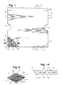
- Organizing and storing device 10 (Fig. 1) is formed as a generally flat frame 12 having two opposite edges 14 and a second pair of opposite edges 16.
- a plurality of generally equally spaced notches 18 are formed in or cut out of edges 14 of frame 12 so that an electrical cord "C" can be wrapped about the frame and within the notches, as shown in Figure 2.
- an electrical cord "C” can be wrapped about the frame and within the notches, as shown in Figure 2.
- one or more individual, interconnected electrical light strings can be wrapped about the frame.
- slits 20 may be provided in frame 12, near each corner thereof, and into which plug ends of the cords can be received and locked.
- flat frame 12 be fabricated of corrugated paper board with the elongated corrugations thereof extending in a direction between the opposite edges of the frame about which the cord is wrapped to provide rigidity and support for the frame in the direction of the wraps in the cord.
- a single ply corrugated board can be used, the preferred embodiment of the invention shown in Figures 1 and 1Acontemplatesthatframe 12 be fabricated of a double-walled construction defined by opposite exterior face sheets 22 and an interior intermediate sheet 24, with elongated corrugations 26 between the interior intermediate sheet and each exteriorface sheet.
- the elongated corrugations between interior sheet 24 and exterior face sheets 22 all extend in a direction between opposite edges 14 of frame 12 within which notches 18 are disposed. This construction gives a double rigidifying and supporting effect to the flat frame.
- Figure 3 shows an alternate embodiment of a device 10' for organizing and storing an electrical wire cord, similar to device 10 in Figures 1-2. Consequently, like numerals have been applied in Figure 3 corresponding to like components described above in relation to Figures 1-2.
- notches 28 are provided in opposite edges 16 of frame 12, in addition to notches 18 in opposite edges 14.
- the elongated corrugations 26' between the top face sheet and the interior sheet of the corrugated construction extend in the direction of opposite edges 14 of the frame
- the elongated corrugations 26" between the interior sheet and the bottom exteriorface sheet of the corrugated construction extend in the direction of opposite edges 16 of the frame.
- corrugations 26" are generally perpendicular to corrugations 26'.
- electrical light strings may be wrapped in loops about opposite edges 14 of frame 12, within notches 18, or the light string may be wound about edges 16, within notches 28, or both.
- This construction might be applicable for use with lightweight "Italian" Christmas tree light bulb strings, whereas the more singularly directed reinforcement construction of device 10 in Figures 1 and 1A is more applicable for heavier duty outdoor Christmas tree light strings where there would be more of a tendency to apply excessive pressures in wrapping the electric cord about the frame.
- corrugated paper board material of frames 12 also lend themselves to being impregnated with a fire proofing or fire retardant substance.
- the invention contemplates a system for organizing and storing electrical wire cords such as the Christmas tree light strings, wherein devices 10 (Fig. 1) and/or 10' (Fig. 3), themselves, can be stored in a container, generally designated 30, between seasonal uses.
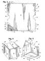
- Figure 4 shows a cutout area 32 of container 30 to illustrate a plurality of devices 10 received in the container in a stacked array.
- Figure 5 shows the container with a lid thereof partially open, and
- Figure 6 shows the container in open condition with one of the devices 10 being lifted out of the container for use.
- at least the two side edges 16 (Figs. 1 and 3) are provided with cutouts 36 to facilitate placing the devices in and lifting the devices out of the container, as by a user's finger(s), in a flat stacked array, instead of an edge-wise array which would cause entanglement problems.
- container 30 is of a box-like configuration fabricated of lightweight, inexpensive corrugated paper board material.
- the container includes a front wall or panel 38, a rear wall or panel 40 and a pair of side walls or panels 42 which combine to define an interior storage compartment, as indicated at 44 in Figure 6.
- Side walls 42 are joined to front and rear walls 38 and 40, respectively, by fold lines 46 and 48, respectively.
- a top lid 50 is joined to the top edge of rear wall 48 by a fold line 52 which is in the form of a "reverse-bend" line.
- a pair of inside bottom wall flaps 54 (Fig. 5) are joined to side walls 42 by fold lines 56, and a second pair of outside bottom wall flaps 58 are joined to front and rear walls 38 and 40 by fold lines 60.
- inwardly foldable flanges 62 are provided along the top edges of side walls 42 for folding inwardly along fold lines 64 to assist in completely closing compartment 44 and to provide rigidity for the top of the side walls, and a front flange 66 extends along the front edge of lid 50 for folding downwardly along a fold line 68 for tucking the lid inside front wall 38 as seen in Figure 4.
- the front wall may have a cutout 70 (Fig. 4) for facilitating lifting the lid and opening the container.
- the invention contemplates a system which includes the combination of devices 10 or 10' for organizing and storing a plurality of electrical wire cords or light strings, and then storing the individual devices within container 30 in an organized stacked array during off-season non-use.
- Both devices 10 (10') and container 30 are fabricated of inexpensive lightweight cardboard material, but the nature and specific construction of the corrugated paper board is used to specific advantages in its structural orientation in relation to organizing and storing the electrical light strings.
- FIG. 7 Another aspect of the invention is shown in Figure 7 and further in the original container blank of Figure 8, wherein container 30, itself, can be folded in a compact condition of a width not significantly wider than the organizing and storing devices 10 (10'), themselves.
- FIG. 7 it can be seen that the various walls or panels of container 30 (Figs. 4-6) are in an accordion-like folded condition, with front and rear walls 38 and 40, respectively, facing outwardly, and with bottom wall flaps 58 depending downwardly therefrom.
- This folded condition of the container defines a package having a width "A" which is only slightly wider than the organizing and storing devices 10 (10'), themselves.
- width "A" is equal to the interior dimensions of compartment 44 plus the thicknesses of the corrugated material.
- the size of the compartment need not be much larger than the dimensions of frames 12 of devices 10 (10'), because the electric cords seat within notches 18 or 28 in the edges of the frame, and the bulbs of the cords can be shifted slightly so as not to become wedged between the edges of the frame and the interior of the container compartment.
- side walls 42 include intermediate or central fold lines 72, whereby the side walls or panels may be folded inwardly between front and rear walls or panels 38 and 40, respectively, in an accordion-folded configuration as shown by the folded condition of flaps 62 in Figure 7 at the top edges of side walls 42. Then, lid 50 can be reverse-bent to lay along the back side of the configuration, as indicated by arrow "D".
- Figure 8 shows a blank "B" from which container 30 (Figs. 4-6) can be formed.
- front and rear walls or panels 38 and 40 respectively, side walls or panels 42, top lid 50, inside bottom flaps 54, and outside bottom flaps 58 all are shown in the flat blank "B" of Figure 8.
- the fold lines described above, along with flanges 62 at the top edges of side panels 42 and front flange 66 at the front edge of lid 50 also are shown in the flat blank configuration.
- Figure 8 shows that rear panel 40 includes a flange 74 joined to its outer edge by a fold line 76.
- blank "B” is folded into a sort of rectangular "chimney” configuration, whereby flange 74 is located inside the right-hand side panel 42, as viewed in Figure 8, and the flange is affixed to the side wall by an appropriate adhesive, whereupon the flange is located at a position indicated by dotted line 78.
- side panels 42 can be folded inwardly along fold lines 72, in an accordion fashion, whereupon the container can be completely folded to its storage or handling condition shown in Figure 7, with lid 50 being folded backwards along the outside of the structure.
- front and rear panels 38 and 40 simply are pulled apart, whereupon side panels 42 open and assume a generally flat configuration from the accordion condition shown in Figure 7.
- Inside bottom flaps 54 then are folded inwardly and, thereafter, outside bottom flaps 56 are folded inwardly as shown in Figure 5.
- the outside bottom flaps have V-shaped notches or cutouts 80 at the mid-point of their free edges, whereby the bottom flaps 56 can be snapped into interengagement as shown at the bottom of Figure 5 without the use of adhesive, tape or other securing means.
- the container shown in Figure 5 then is ready to be loaded with a plurality of the organizing and storing devices 10 (10') as indicated in Figure 6 by arrow "C".
- lid 52 is closed as shown in Figure 4, and the organizing and storing system of the invention, including the container and its stored organizing and storing devices, can be packed away for use at the next Christmas season.
- a plurality of devices 10 have been fabricated on the order of fourteen-inches square, with a container 30 having a storage compartment 44 fourteen and one fourth inches square and twelve inches deep.
- a system can accommodate five sets of conventional outdoor Christmas lights, seven sets of conventional indoor Christmas lights, nine sets of Italian Christmas lights without reflectors and twelve sets of conventional Italian Christmas lights with reflectors, all for a minimal expense due to the lightweight cost-effective construction of the system of the invention.
Abstract
Description
- This invention generally relates to devices orsys- tems for organizing, packaging and storing electrical light strings, such as Christmas tree lights strung on an electric cord.
- Entanglement continues to be a major problem in organizing, packaging and storing cords or other strings wherein a plurality of objects are spaced therealong in a predetermined succession. The most common problematic area involves the use, handling and storage of Christmas tree light strings. However, other types of lines or cords such as fishing lines, knotted depth lines, etc. also are subject to entanglement problems.
- In the area of Christmas tree light strings, light sets traditionally have been used to decorate Christmas trees, objects and houses, both indoor and outdoor, during the Christmas season. After the season is over, the lights are dismantled and stored for the next season.
- When first purchased, strings of Christmas tree lights generally come in flat packages or boxes which are designed primarily for display purposes or for stacking on retail store shelves. Unfortunately, the original packages or boxes are not particularly suitable for storing the sets of lights in an orderly fashion between seasonal usage. For instance, a very common type of original package utilizes a relatively thick polystyrene foam tray which has rows of cavities therein for individually receiving the lights. Channels may connect the cavities and wherein the electric cord is looped or, literally, "stuffed". Although it is relatively easy for a user to simply pull a set of lights out of such a packaging construction, it becomes quite tedious to reassemble the lights back into their original packaging.
- Because of the unsuitability of original packaging for such strings of lights, and because the sets are rather cumbersome to handle, often being eight feet or more in length, most individuals simply stuff the sets of lights in boxes or bags for storage. Unfortunately, when the next Christmas season arrives, the sets of lights are all tangled. Not only is it quite time consuming to untangle the sets of lights, but light bulbs often are broken in the process. Even the untangled sets of lights are still cumbersome to install on a tree, for example, because a long string of lights is difficult to maneuver around the tree and into and out of the branches thereof, during which still more bulbs become broken.
- A variety of proposals have been suggested for providing devices or systems for organizing and storing Christmas tree light strings, such as those disclosed in U.S. Patents Nos. 1,981,731, dated November 20, 1934; 2,984,347, dated May 16,1961; 3,626,495, dated December 7,1971; 4,917,323, dated April 17, 1990; 5,033,619, dated July 23, 1991; 5,064,067, dated November 12,1991; and 5,168,999, dated December 8, 1992. With such a variety of known proposals for solving the problems of organizing and storing Christmas tree light strings, it is very surprising that very few, if any, such proposals have come to fruition on the commercial market in most retail establishments. In reviewing such proposals, the lack of success becomes apparent in that many proposed devices are no less cumbersome nor less complicated than the original, problematic retail packaging in which the sets of lights were purchased. Or, and quite importantly, most prior art devices simply are too expensive. Most consumers are reluctant to spend a great deal of money on seasonal items, particularly items which are used only once a year, and particularly items such as organizing and storing devices which never are seen or displayed in the first place.
- There is a definite need for an extremely simple, user friendly and very inexpensive device and/or system for organizing and storing electric cords such as Christmas tree light strings. This invention is directed to satisfying that need and solving the problems outlined above.
- An object, therefore, of the invention is to provide a new and improved device for organizing and storing an electrical wire cord such as an electrical light string having a plurality of electric bulbs joined by an electric cord.
- In the exemplary embodiment of the invention, genarally, the device is formed by a generally flat frame having at least two opposite edges provided with a plurality of notches so that the cord may be wrapped about the frame and within the notches. The flat frame is fabricated of thin corrugated paper board with elongated corrugations thereof extending in a direction between the two opposite edges to provide rigidity and support for the frame in the direction of the wraps of the cord.
- In a preferred embodiment of the invention, the frame is fabricated of a double-walled construction defined by opposite exterior face sheets and at least one interior intermediate sheet, with elongated corrugations between the interior intermediate sheet and each exterior face sheet. In one embodiment, the elongated corrugations between the interior intermediate sheet and each exterior face sheet all extend in a direction between the two opposite edges of the frame.
- In an alternate embodiment of the invention, the elongated corrugations between the interior intermediate sheet and one of the exterior face sheets extend in the direction between the two opposite edges, but the elongated corrugations between the interior intermediate sheet and the other of the exterior face sheets extend in a direction between a second pair of opposite edges which, themselves, may have notches therein.
- According to another aspect of the invention, a box-like container is provided for use in combination with a plurality of the organizing and storing devices or frames. Specifically, the container defines a storage compartment sized for receiving a plurality of the organizing and storing devices in a stacked array. Preferably, the container is fabricated of similar, inexpensive thin corrugated paper board material.
- As disclosed herein, a system for organizing and storing electrical light strings would include a plurality of generally flat frames, each frame being of a polygonal configuration (such as rectangular) defined by peripheral edges about which a cord may be wrapped. The box-like container defines a storage compartment of a polygonal configuration (such as rectangular) complementary to the polygonal configuration of the frames. The compartment is sized for receiving a plurality of the frames in a stacked array with the cords wrapped thereabout.
- Other features include providing the frames with cutouts in the peripheral edges thereof to facilitate lifting the frames out of the container. The frames may be provided with slits in the peripheral edges thereof for receiving and locking plug ends of the cords.
- According to still a further aspect of the invention, the box-like container is fabricated from a blank which includes at least a plurality of side panels for forming the polygonal storage compartment. With a rectangular configuration, four side panels would be provided and joined by fold lines so that the container may be opened and closed between an unfolded condition defining the polygonal or rectangular storage compartment and a folded generally flat condition with the side panels in a general accordion configuration. To facilitate folding the container to a width generally the same width as the organizing and storing devices or frame, themselves, two opposite side panels are provided with intermediate fold lines, whereby the opposite side panels may be folded inwardly between the other two side panels within the bounds thereof.
- Other objects, features and advantages of the invention will be apparent from the following detailed description taken in connection with the accompanying drawings.
- The features of this invention which are believed to be novel are set forth with particularity in the appended claims. The invention, together with its objects and the advantages thereof, may be best understood by reference to the following description taken in conjunction with the accompanying drawings, in which like reference numerals identify like elements in the figures and in which:
- FIGURE 1 is a plan view, partially cut away, of one of the organizing and storing devices of the invention;
- FIGURE 1A is fragmented section, on an enlarged scale, taken generally along
line 1A-1A in Figure 1; - FIGURE 2 is a perspective view of the device of Figure 1, with an electrical light string wrapped thereabout;
- FIGURE 3 is a view similar to that of Figure 1, of an alternate embodiment of the invention;
- FIGURE 4 is a top perspective view of a box-like container, partially broken away to show a plurality of the devices of Figures 1-3 stacked therewithin;
- FIGURE 5 is a bottom perspective view of the container, with the lid fragmented and in open condition;
- FIGURE 6 is a top perspective view of the container, with the lid open and illustrating a plurality of the organizing and storing devices being stacked therewithin;
- FIGURE 7 is a perspective view of the container in its closed or storage condition; and
- FIGURE 8 is a plan view of a blank from which the container is formed.
- Referring to the drawings in greater detail, and first to Figure 1, a first embodiment of a device, generally designated 10, is illustrated for organizing and storing an electrical wire cord such as an electrical Christmas tree light string having a plurality of electric bulbs joined by an electric cord. It should be understood that, although the practical applicability of the invention has been emphasized herein as directed to Christmas tree light strings, the invention is equally applicable for other strings of objects with which the invention can be used.
- Organizing and storing device 10 (Fig. 1) is formed as a generally
flat frame 12 having twoopposite edges 14 and a second pair ofopposite edges 16. In the embodiment of Figure 1, a plurality of generally equally spacednotches 18 are formed in or cut out ofedges 14 offrame 12 so that an electrical cord "C" can be wrapped about the frame and within the notches, as shown in Figure 2. Depending upon the size of the frame, one or more individual, interconnected electrical light strings can be wrapped about the frame. As best seen in Figure 1,slits 20 may be provided inframe 12, near each corner thereof, and into which plug ends of the cords can be received and locked. - The invention contemplates that
flat frame 12 be fabricated of corrugated paper board with the elongated corrugations thereof extending in a direction between the opposite edges of the frame about which the cord is wrapped to provide rigidity and support for the frame in the direction of the wraps in the cord. Although a single ply corrugated board can be used, the preferred embodiment of the invention shown in Figures 1 and1Acontemplatesthatframe 12 be fabricated of a double-walled construction defined by oppositeexterior face sheets 22 and an interiorintermediate sheet 24, withelongated corrugations 26 between the interior intermediate sheet and each exteriorface sheet. In the embodiment of Figures 1 and 1A, the elongated corrugations betweeninterior sheet 24 andexterior face sheets 22 all extend in a direction betweenopposite edges 14 offrame 12 within whichnotches 18 are disposed. This construction gives a double rigidifying and supporting effect to the flat frame. - Figure 3 shows an alternate embodiment of a device 10' for organizing and storing an electrical wire cord, similar to
device 10 in Figures 1-2. Consequently, like numerals have been applied in Figure 3 corresponding to like components described above in relation to Figures 1-2. - More particularly, in the embodiment of the device 10' shown in Figure 3,
notches 28 are provided inopposite edges 16 offrame 12, in addition tonotches 18 inopposite edges 14. In addition, looking at the bottom left-hand comer offrame 12 in Figure 3, it can be seen that the elongated corrugations 26' between the top face sheet and the interior sheet of the corrugated construction extend in the direction ofopposite edges 14 of the frame, while theelongated corrugations 26" between the interior sheet and the bottom exteriorface sheet of the corrugated construction extend in the direction ofopposite edges 16 of the frame. In other words, corrugations 26" are generally perpendicular to corrugations 26'. With the construction of Figure 3, electrical light strings may be wrapped in loops aboutopposite edges 14 offrame 12, withinnotches 18, or the light string may be wound aboutedges 16, withinnotches 28, or both. This construction might be applicable for use with lightweight "Italian" Christmas tree light bulb strings, whereas the more singularly directed reinforcement construction ofdevice 10 in Figures 1 and 1A is more applicable for heavier duty outdoor Christmas tree light strings where there would be more of a tendency to apply excessive pressures in wrapping the electric cord about the frame. - The corrugated paper board material of
frames 12 also lend themselves to being impregnated with a fire proofing or fire retardant substance. - Referring to Figure 4, the invention contemplates a system for organizing and storing electrical wire cords such as the Christmas tree light strings, wherein devices 10 (Fig. 1) and/or 10' (Fig. 3), themselves, can be stored in a container, generally designated 30, between seasonal uses. Figure 4 shows a
cutout area 32 ofcontainer 30 to illustrate a plurality ofdevices 10 received in the container in a stacked array. Figure 5 shows the container with a lid thereof partially open, and Figure 6 shows the container in open condition with one of thedevices 10 being lifted out of the container for use. To that end, it should be noted that at least the two side edges 16 (Figs. 1 and 3) are provided withcutouts 36 to facilitate placing the devices in and lifting the devices out of the container, as by a user's finger(s), in a flat stacked array, instead of an edge-wise array which would cause entanglement problems. - More particularly,
container 30 is of a box-like configuration fabricated of lightweight, inexpensive corrugated paper board material. The container includes a front wall orpanel 38, a rear wall orpanel 40 and a pair of side walls orpanels 42 which combine to define an interior storage compartment, as indicated at 44 in Figure 6.Side walls 42 are joined to front andrear walls fold lines top lid 50 is joined to the top edge ofrear wall 48 by afold line 52 which is in the form of a "reverse-bend" line. A pair of inside bottom wall flaps 54 (Fig. 5) are joined toside walls 42 byfold lines 56, and a second pair of outside bottom wall flaps 58 are joined to front andrear walls fold lines 60. Lastly, as seen in Figure 6, inwardlyfoldable flanges 62 are provided along the top edges ofside walls 42 for folding inwardly alongfold lines 64 to assist in completely closingcompartment 44 and to provide rigidity for the top of the side walls, and afront flange 66 extends along the front edge oflid 50 for folding downwardly along afold line 68 for tucking the lid insidefront wall 38 as seen in Figure 4. The front wall may have a cutout 70 (Fig. 4) for facilitating lifting the lid and opening the container. - As stated above, the invention contemplates a system which includes the combination of
devices 10 or 10' for organizing and storing a plurality of electrical wire cords or light strings, and then storing the individual devices withincontainer 30 in an organized stacked array during off-season non-use. Both devices 10 (10') andcontainer 30 are fabricated of inexpensive lightweight cardboard material, but the nature and specific construction of the corrugated paper board is used to specific advantages in its structural orientation in relation to organizing and storing the electrical light strings. - Another aspect of the invention is shown in Figure 7 and further in the original container blank of Figure 8, wherein
container 30, itself, can be folded in a compact condition of a width not significantly wider than the organizing and storing devices 10 (10'), themselves. - More particularly, referring to Figure 7, it can be seen that the various walls or panels of container 30 (Figs. 4-6) are in an accordion-like folded condition, with front and
rear walls compartment 44 plus the thicknesses of the corrugated material. The size of the compartment need not be much larger than the dimensions offrames 12 of devices 10 (10'), because the electric cords seat withinnotches - In order to enable the container to be folded into its narrow configuration as shown in Figure 7,
side walls 42 include intermediate orcentral fold lines 72, whereby the side walls or panels may be folded inwardly between front and rear walls orpanels flaps 62 in Figure 7 at the top edges ofside walls 42. Then,lid 50 can be reverse-bent to lay along the back side of the configuration, as indicated by arrow "D". - Lastly, Figure 8 shows a blank "B" from which container 30 (Figs. 4-6) can be formed. Specifically, front and rear walls or
panels panels 42,top lid 50, inside bottom flaps 54, and outside bottom flaps 58 all are shown in the flat blank "B" of Figure 8. The fold lines described above, along withflanges 62 at the top edges ofside panels 42 andfront flange 66 at the front edge oflid 50 also are shown in the flat blank configuration. Figure 8 shows thatrear panel 40 includes aflange 74 joined to its outer edge by afold line 76. In assembly, blank "B" is folded into a sort of rectangular "chimney" configuration, wherebyflange 74 is located inside the right-hand side panel 42, as viewed in Figure 8, and the flange is affixed to the side wall by an appropriate adhesive, whereupon the flange is located at a position indicated by dottedline 78. From this chimney configuration,side panels 42 can be folded inwardly alongfold lines 72, in an accordion fashion, whereupon the container can be completely folded to its storage or handling condition shown in Figure 7, withlid 50 being folded backwards along the outside of the structure. - When it is desirable to convert the container from its folded condition shown in Figure 7 to its unfolded or open condition shown in Figures 4-6, front and
rear panels side panels 42 open and assume a generally flat configuration from the accordion condition shown in Figure 7. Insidebottom flaps 54 then are folded inwardly and, thereafter, outside bottom flaps 56 are folded inwardly as shown in Figure 5. The outside bottom flaps have V-shaped notches orcutouts 80 at the mid-point of their free edges, whereby the bottom flaps 56 can be snapped into interengagement as shown at the bottom of Figure 5 without the use of adhesive, tape or other securing means. - The container shown in Figure 5 then is ready to be loaded with a plurality of the organizing and storing devices 10 (10') as indicated in Figure 6 by arrow "C". When the container is loaded with the devices,
lid 52 is closed as shown in Figure 4, and the organizing and storing system of the invention, including the container and its stored organizing and storing devices, can be packed away for use at the next Christmas season. - In actual practice, a plurality of
devices 10 have been fabricated on the order of fourteen-inches square, with acontainer 30 having astorage compartment 44 fourteen and one fourth inches square and twelve inches deep. Such a system can accommodate five sets of conventional outdoor Christmas lights, seven sets of conventional indoor Christmas lights, nine sets of Italian Christmas lights without reflectors and twelve sets of conventional Italian Christmas lights with reflectors, all for a minimal expense due to the lightweight cost-effective construction of the system of the invention. - It will be understood that the invention may be embodied in other specific forms without departing from the spirit or central characteristics thereof. The present examples and embodiments, therefore, are to be considered in all respects as illustrative and not restrictive, and the invention is not to be limited to the details given herein.
Claims (17)
Applications Claiming Priority (2)
| Application Number | Priority Date | Filing Date | Title |
|---|---|---|---|
| US1300793A | 1993-02-03 | 1993-02-03 | |
| US13007 | 1993-02-03 |
Publications (2)
| Publication Number | Publication Date |
|---|---|
| EP0610074A2 true EP0610074A2 (en) | 1994-08-10 |
| EP0610074A3 EP0610074A3 (en) | 1994-12-28 |
Family
ID=21757831
Family Applications (1)
| Application Number | Title | Priority Date | Filing Date |
|---|---|---|---|
| EP94300768A Withdrawn EP0610074A3 (en) | 1993-02-03 | 1994-02-02 | A device and system for organizing and storing electrical light strings. |
Country Status (2)
| Country | Link |
|---|---|
| EP (1) | EP0610074A3 (en) |
| CA (1) | CA2114407A1 (en) |
Cited By (2)
| Publication number | Priority date | Publication date | Assignee | Title |
|---|---|---|---|---|
| EP1152184A1 (en) * | 2000-05-03 | 2001-11-07 | Pui-Hing Tsui | Lighted frame kit and methods of distributing and assembling same |
| US6394623B1 (en) | 2000-07-14 | 2002-05-28 | Neon King Limited | Translucent flexible rope light and methods of forming and using same |
Citations (5)
| Publication number | Priority date | Publication date | Assignee | Title |
|---|---|---|---|---|
| US2984347A (en) * | 1958-10-01 | 1961-05-16 | Donald W Kalinchuk | Packaging and storage devices for cords strung with a succession of spaced objects |
| US3384227A (en) * | 1966-08-29 | 1968-05-21 | William L. Spatz | Christmas tree lights storage container |
| US3878941A (en) * | 1973-08-20 | 1975-04-22 | Gerald Kelner | Package for Christmas tree light bulbs |
| US4744464A (en) * | 1985-10-31 | 1988-05-17 | General Electric Company | Ribbon blown glass article transport |
| US5094067A (en) * | 1988-08-04 | 1992-03-10 | Carding Specialists (Canada) Limited | Yarn re-structuring method and apparatus |
-
1994
- 1994-01-27 CA CA 2114407 patent/CA2114407A1/en not_active Abandoned
- 1994-02-02 EP EP94300768A patent/EP0610074A3/en not_active Withdrawn
Patent Citations (5)
| Publication number | Priority date | Publication date | Assignee | Title |
|---|---|---|---|---|
| US2984347A (en) * | 1958-10-01 | 1961-05-16 | Donald W Kalinchuk | Packaging and storage devices for cords strung with a succession of spaced objects |
| US3384227A (en) * | 1966-08-29 | 1968-05-21 | William L. Spatz | Christmas tree lights storage container |
| US3878941A (en) * | 1973-08-20 | 1975-04-22 | Gerald Kelner | Package for Christmas tree light bulbs |
| US4744464A (en) * | 1985-10-31 | 1988-05-17 | General Electric Company | Ribbon blown glass article transport |
| US5094067A (en) * | 1988-08-04 | 1992-03-10 | Carding Specialists (Canada) Limited | Yarn re-structuring method and apparatus |
Cited By (2)
| Publication number | Priority date | Publication date | Assignee | Title |
|---|---|---|---|---|
| EP1152184A1 (en) * | 2000-05-03 | 2001-11-07 | Pui-Hing Tsui | Lighted frame kit and methods of distributing and assembling same |
| US6394623B1 (en) | 2000-07-14 | 2002-05-28 | Neon King Limited | Translucent flexible rope light and methods of forming and using same |
Also Published As
| Publication number | Publication date |
|---|---|
| EP0610074A3 (en) | 1994-12-28 |
| CA2114407A1 (en) | 1994-08-04 |
Similar Documents
| Publication | Publication Date | Title |
|---|---|---|
| US5941476A (en) | Portable enclosure for storage and dispensing of multiple paper rolls | |
| US5141149A (en) | Multiple use plant shipping and display container | |
| US5287965A (en) | Light storage device | |
| US5897084A (en) | Folding trash bag expanding form and holder | |
| US4140218A (en) | Wrap for polygonal prism shaped articles | |
| US7980452B2 (en) | Covered container for enclosing a food product or the like | |
| US20070051662A1 (en) | Packaging for electrical extension cord | |
| US6146018A (en) | Gift package | |
| US6045263A (en) | Gift package | |
| US5316156A (en) | Display rack | |
| US6000849A (en) | Gift package | |
| US20020125161A1 (en) | Box for storing and dispensing cable | |
| CA1163245A (en) | Roll dispensing container | |
| US4993318A (en) | Newspaper bundler | |
| US5282545A (en) | Storage device with liner for tying and removal of bundled papers | |
| US2932384A (en) | Flower display holder | |
| EP0610074A2 (en) | A device and system for organizing and storing electrical light strings | |
| CA2200025A1 (en) | Packaging structure for decorative bow | |
| US4239110A (en) | Container for packaging wire roll | |
| US6334536B1 (en) | Hanging ornament storage container | |
| US2736427A (en) | Cut flower package | |
| US2743862A (en) | Folding display box | |
| JP3234571U (en) | Lure fixing member and lure packaging box | |
| JPH0621901Y2 (en) | Bottle packaging | |
| US3989203A (en) | Creel for pile fabrics having fold-up end assemblies |
Legal Events
| Date | Code | Title | Description |
|---|---|---|---|
| PUAI | Public reference made under article 153(3) epc to a published international application that has entered the european phase |
Free format text: ORIGINAL CODE: 0009012 |
|
| AK | Designated contracting states |
Kind code of ref document: A2 Designated state(s): AT CH DE DK ES FR GB GR IE IT LI NL PT SE |
|
| PUAL | Search report despatched |
Free format text: ORIGINAL CODE: 0009013 |
|
| AK | Designated contracting states |
Kind code of ref document: A3 Designated state(s): AT CH DE DK ES FR GB GR IE IT LI NL PT SE |
|
| 17P | Request for examination filed |
Effective date: 19950321 |
|
| 17Q | First examination report despatched |
Effective date: 19951025 |
|
| GRAG | Despatch of communication of intention to grant |
Free format text: ORIGINAL CODE: EPIDOS AGRA |
|
| GRAH | Despatch of communication of intention to grant a patent |
Free format text: ORIGINAL CODE: EPIDOS IGRA |
|
| STAA | Information on the status of an ep patent application or granted ep patent |
Free format text: STATUS: THE APPLICATION IS DEEMED TO BE WITHDRAWN |
|
| 18D | Application deemed to be withdrawn |
Effective date: 19961106 |