EP0612134A2 - Programmable battery controllers - Google Patents
Programmable battery controllers Download PDFInfo
- Publication number
- EP0612134A2 EP0612134A2 EP94300759A EP94300759A EP0612134A2 EP 0612134 A2 EP0612134 A2 EP 0612134A2 EP 94300759 A EP94300759 A EP 94300759A EP 94300759 A EP94300759 A EP 94300759A EP 0612134 A2 EP0612134 A2 EP 0612134A2
- Authority
- EP
- European Patent Office
- Prior art keywords
- battery
- charge
- microcontroller
- discharge
- recited
- Prior art date
- Legal status (The legal status is an assumption and is not a legal conclusion. Google has not performed a legal analysis and makes no representation as to the accuracy of the status listed.)
- Withdrawn
Links
Images


Classifications
-
- G—PHYSICS
- G01—MEASURING; TESTING
- G01R—MEASURING ELECTRIC VARIABLES; MEASURING MAGNETIC VARIABLES
- G01R31/00—Arrangements for testing electric properties; Arrangements for locating electric faults; Arrangements for electrical testing characterised by what is being tested not provided for elsewhere
- G01R31/36—Arrangements for testing, measuring or monitoring the electrical condition of accumulators or electric batteries, e.g. capacity or state of charge [SoC]
- G01R31/3644—Constructional arrangements
- G01R31/3648—Constructional arrangements comprising digital calculation means, e.g. for performing an algorithm
-
- H—ELECTRICITY
- H02—GENERATION; CONVERSION OR DISTRIBUTION OF ELECTRIC POWER
- H02J—CIRCUIT ARRANGEMENTS OR SYSTEMS FOR SUPPLYING OR DISTRIBUTING ELECTRIC POWER; SYSTEMS FOR STORING ELECTRIC ENERGY
- H02J7/00—Circuit arrangements for charging or depolarising batteries or for supplying loads from batteries
- H02J7/0047—Circuit arrangements for charging or depolarising batteries or for supplying loads from batteries with monitoring or indicating devices or circuits
- H02J7/0048—Detection of remaining charge capacity or state of charge [SOC]
-
- H—ELECTRICITY
- H02—GENERATION; CONVERSION OR DISTRIBUTION OF ELECTRIC POWER
- H02J—CIRCUIT ARRANGEMENTS OR SYSTEMS FOR SUPPLYING OR DISTRIBUTING ELECTRIC POWER; SYSTEMS FOR STORING ELECTRIC ENERGY
- H02J7/00—Circuit arrangements for charging or depolarising batteries or for supplying loads from batteries
- H02J7/007—Regulation of charging or discharging current or voltage
- H02J7/00712—Regulation of charging or discharging current or voltage the cycle being controlled or terminated in response to electric parameters
-
- G—PHYSICS
- G01—MEASURING; TESTING
- G01R—MEASURING ELECTRIC VARIABLES; MEASURING MAGNETIC VARIABLES
- G01R19/00—Arrangements for measuring currents or voltages or for indicating presence or sign thereof
- G01R19/165—Indicating that current or voltage is either above or below a predetermined value or within or outside a predetermined range of values
- G01R19/16533—Indicating that current or voltage is either above or below a predetermined value or within or outside a predetermined range of values characterised by the application
- G01R19/16538—Indicating that current or voltage is either above or below a predetermined value or within or outside a predetermined range of values characterised by the application in AC or DC supplies
- G01R19/16542—Indicating that current or voltage is either above or below a predetermined value or within or outside a predetermined range of values characterised by the application in AC or DC supplies for batteries
-
- G—PHYSICS
- G01—MEASURING; TESTING
- G01R—MEASURING ELECTRIC VARIABLES; MEASURING MAGNETIC VARIABLES
- G01R31/00—Arrangements for testing electric properties; Arrangements for locating electric faults; Arrangements for electrical testing characterised by what is being tested not provided for elsewhere
- G01R31/36—Arrangements for testing, measuring or monitoring the electrical condition of accumulators or electric batteries, e.g. capacity or state of charge [SoC]
- G01R31/3644—Constructional arrangements
- G01R31/3646—Constructional arrangements for indicating electrical conditions or variables, e.g. visual or audible indicators
-
- Y—GENERAL TAGGING OF NEW TECHNOLOGICAL DEVELOPMENTS; GENERAL TAGGING OF CROSS-SECTIONAL TECHNOLOGIES SPANNING OVER SEVERAL SECTIONS OF THE IPC; TECHNICAL SUBJECTS COVERED BY FORMER USPC CROSS-REFERENCE ART COLLECTIONS [XRACs] AND DIGESTS
- Y10—TECHNICAL SUBJECTS COVERED BY FORMER USPC
- Y10S—TECHNICAL SUBJECTS COVERED BY FORMER USPC CROSS-REFERENCE ART COLLECTIONS [XRACs] AND DIGESTS
- Y10S320/00—Electricity: battery or capacitor charging or discharging
- Y10S320/18—Indicator or display
- Y10S320/21—State of charge of battery
Definitions
- This invention relates to a programmable battery controller and more particularly to a programmble apparatus, system and method for more accurately controlling and/or monitoring battery charge.
- Battery monitoring systems are commonly used to notify a portable computer user when a rechargeable battery needs recharging.
- Conventional battery monitoring systems often implement a software program that relies on a computer's hardware configuration and the power needed to run the components and peripherals. The software then monitors the usage of the components and peripherals to approximate the battery's drain rate and the remaining charge on the battery.
- TSR terminate and stay resident
- Typical battery voltage monitors often cannot and do not indicate when a full discharge has occurred and that recharge is now needed to maintain optimal battery performance.
- Nickel cadmium batteries are commonly used in portable computers. However, nickel cadmium batteries are susceptible to the memory effect--they might not recharge fully if they're not first completely discharged. For example, if a battery is repeatedly recharged before reaching a low battery level, a three-hour battery may only last for one hour. A full battery discharge helps eliminate the memory effect.
- Conventional charge monitoring devices often do not store non-linear discharge information. As a result the computer user must know of battery characteristics, and monitor battery usage to determine when a discharge is necessary and how long discharge is needed in order to prolong battery life.
- Some conventional monitoring devices use discrete components to measure the actual current drain on a battery. However such systems are bulky, do not provide flexibility, and do not exhibit accuracy. Battery discharge rates vary according to the batteries chemical composition, temperature, storage time, age of the battery, and load. Computer users find desirable battery monitoring systems which are not bulky and which can (i) determine when a discharge cycle is needed, (ii) determine an optimal discharge period, and (iii) perform the discharge and recharge cycles automatically under varying loads and operating temperatures.
- the problems outlined above are in large measure solved by the programmable battery controller described herein, and which provides a small accurate, real time, and flexible low power battery monitoring system that allows user input.
- the controller can accurately monitor temperature and charge characteristics as well as battery output variations over the life of the battery. Adjusting to battery output variations and executing full discharge cycles, the controller provides a controlling and monitoring system which can prolong battery life and enhance battery performance. Enhanced battery performance achieves more reliable battery operation, provides longer battery life from each battery charge, and allows smaller batteries to achieve the same system tasks.
- the battery monitoring system can be used in any programmable portable device, and allows for the design of smaller and lighter portable devices such as, for example, portable computers (i.e., notebooks, subnotebooks, laptops and/or palmtops) or any other host portable device having microprocessor- based operation.
- portable computers i.e., notebooks, subnotebooks, laptops and/or palmtops
- microprocessor- based operation any other host portable device having microprocessor- based operation.
- a programmable battery charger offers flexibility forfuture battery types and characteristics. Advances in rechargeable nickel cadmium (NICAD), lead-acid, nickel metal hydride (NMH), lithium, and carbon batteries provide a variety of new operating characteristics. Operating characteristics can include variations in charge current, storage duration, temperature degradation, battery age, and battery discharge rates. The programmable nature of the controller permits the design of battery monitoring parameters suitable to a particular battery's operating characteristics.
- a further feature of the controller is to allow a user to selectively change parameters.
- a user can input monitoring parameters to adapt to special circumstances, such as, for example, delaying a discharge cycle until the user manually initiates the discharge. Otherwise, once the parameters are set, discharge cycles can begin automatically without user interface.
- the full programmability of the battery controller allows the presentation of battery charge data and battery status on future display devices and on present display devices such as on computer monitor cathode ray tubes (CRTs), icon displays (e.g., liquid crystal displays (LCDs), and light emitting diode (LED) indicators.
- CTRs computer monitor cathode ray tubes
- icon displays e.g., liquid crystal displays (LCDs)
- LED light emitting diode
- the programmable controller further allows use of preset battery monitoring parameters.
- a user need not have any battery expertise or special battery knowledge. Battery monitoring and maintenance is transparent to the user. Thus, the user need not know the special characteristics of a battery nor need he or she know when discharge and recharge cycles are necessary.
- the controller automatically monitors and controls the battery charge based on the type of battery used, the temperature of the battery, the age of the battery, and the battery charge capacity.
- the controller allows the use of existing hardware on a portable computer system (or host system).
- Most portable computers have a keyboard, keyboard interface, and keyboard microcontroller to manage keyboard input.
- the software routines of the present invention use the pre-existing keyboard microcontroller hardware to help monitor battery parameters.
- additional circuitry is not required by the host system.
- a reduction in battery monitoring hardware lessens space, weight and power requirements.
- weight and battery life provide competitive product advantages.
- a reduction in battery monitoring hardware lessens manufacturing and maintenance costs.
- Other advantages of the present controller allow adaptation to other portable, battery driven host devices beyond keyboard entry microcontrollers.
- Such devices include microcontroller-based units which directly control peripherals such as pen-based input devices, mouse-based input devices, touch input devices, or scanning devices.
- the device includes a system microprocessor, a computer display, a keyboard interface gate array, a keyboard microcontroller, a charge gauge integrated circuit, and an icon display.
- Charge gauge software allows the keyboard microcontroller to monitor both the keyboard and the battery while also driving control signals to the host computer and battery charger.
- the controller or charge gauging software allows a user to configure parameters to meet system needs.
- the battery controller system automatically determines when rechargeable battery discharge and charge cycles are needed. The charge controller system then notifies the user that a discharge is necessary to obtain maximum battery life. If enabled, the battery controller system wi execute discharge and charge cycles automatically without interfering with the user's current operation/application.
- the programmable controller also supports two display devices to transmit the battery status information to the computer user.
- One display device is a small LCD readout mounted on or near the computer keyboard called the icon display.
- the icon display shows the battery charge level as a fuel or charge meter with icons between full and empty. A battery icon, and ten other charge meter icons range from empty to full in 10% charge steps. Thus, if six of the charge meter icons are displayed, then 60% of battery charge remains.
- the controller system also has a capacity for, and can support, sixteen charge meter icons in order to display fractions of capacity similar to an automobile fuel guage (e.g., 1/4, 1/2, 3/4, etc.).
- the second display device is a conventional computer display.
- the charge gauge software presents the battery temperature, charge status, and user configured parameters in a menu format.
- the computer user presses a combination of keys (e.g., control-alt-P) on the computer keyboard to bring up the power control menu. Once in this menu, the computer user can select options and obtain battery status information.
- keys e.g., control-alt-P
- charge gauge software follows preset battery monitoring parameters. This allows the user to interact with the computer user to alter the battery monitoring parameters as desired.
- the battery monitoring parameters include items such as the low level battery threshold, battery warning messages, discharge cycle enable, and low battery audio warnings. Based on the battery monitoring parameters, the charge gauge software continuously updates battery data such as charge levels and battery pack internal temperature.
- Fig. 1 illustrates a block diagram of a programmable battery controller 8 or battery charge gauge system.
- the battery controller or charge gauge system 8 includes a system microprocessor 10, a computer monitor or display 12, a keyboard gate array 14, a microcontroller 16, a charge gauge integrated circuit 18, and an icon display 20.
- System microprocessor 10 runs charge gauge software necessary to interface to microcontroller 16 via keyboard gate array 14.
- microcontroller 16 monitors the charge gauge integrated circuit 18 and obtains battery data such as charge, temperature, and battery status information.
- Microcontroller 16 communicates the battery information to the system microprocessor 10 which displays the battery charge, temperature and battery status information to the computer display 12.
- an icon display 20 may be used to indicate battery-charge status.
- Icon display 20 includes a small liquid crystal display (LCD) readout mounted on or near the computer keyboard. LCD readout is active independent of computer display 12.
- LCD liquid crystal display
- System microprocessor 10 acts as a central processing unit that executes an operating system.
- the operating system is an integrated collection of supervisory programs and subroutines that control the execution of the computer programs and performs special system functions.
- One such special function of the operating system is to control the basic input and output of the charge gauge system.
- the basic input and output or "BIOS" routines work closely with the hardware to support the transfer of information between elements of the system.
- the BIOS routines also communicate with microcontroller 16, by reading data from and writing data to the internal registers on the microcontroller 16.
- Microcontroller 16 communicates with the BIOS by asserting an interrupt.
- the microcontroller 16 executes its own programs and only interrupts the system microprocessor 10 when some action needs to be taken.
- the BIOS will stop the present program running on the system microprocessor 10 and check the status of the microcontroller 16 by reading data from the microcontroller's internal registers via keyboard gate array 14. Depending on the status of the microcontroller's internal registers, the BIOS will warn the computer user about a low battery charge level, when a discharge cycle request is made, or when a battery is replaced.
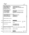
- the power management BIOS routine incorporates charge gauge software and a power control menu 22, as shown in Fig. 2.
- Power control menu 22 allows a user to define the power monitoring characteristics. A user enters the power control menu 22 by pressing a series of keys on the keyboard. In the preferred exemplary embodiment the user presses Cntl-Alt-P on the computer keyboard and the power control menu 22 is then displayed on the computer display 12. The user can then interacts with and/or control the battery by responding, via the keyboard, to the menu 22 prompts.
- the power control menu 22 displays battery data such as the current battery charge 24 remaining on the battery and the current battery temperature 26. Battery charge 24 and temperature 26 are expressed as a bar gauge indicator as shown. Power control menu 22 also displays battery monitor parameters such as low battery setting 28, the discharge cycle 30, and low battery audio warning 32. "Maintenance discharge requested” and “discharge cycle permitted” are preferrably displayed only when charge guage circuit 18 has requested a discharge cycle.
- the user defines the battery monitoring parameters by altering the various settings.
- the charge gauge software will utilize the battery monitoring parameters to monitor the computer's battery. For example, the low battery level setting defines the charge level for a low battery warning. If the user changes the low battery level setting 28, from 10% to 20%, the computer will warn the user to recharge the battery when 20% of the charge remains. Likewise, the user can enable automatic discharge cycle by changing settings 30 from “no" to "yes”. Automatic discharge will occur periodically without user interaction.
- Low battery audio warning 32 can be enabled to audibly warn the user of a low battery.
- Host system microprocessor 10 is commonly configured by those skilled in this art to run a standard system BIOS providing all standard BIOS routines including charge gauge software routines.
- System microprocessor 10 may include any AT/XT IBMo-compatible microprocessor such as a 386, 486 or derivative microprocessor architecture manufactured by, e.g., Intel Corp. of Santa Clara, CA, or Advanced Micro Devices, Inc. of Sunny- vale, CA.
- Microprocessor 10 preferably operates at or near 3.3 V. It is important to note, however, that other microprocessors and operating voltage levels may be used provided they are capable of running the BIOS routines herein described.
- BIOS running on system microprocessor 10 communicates to the microcontroller 16 via the keyboard gate array 14.
- a bidirectional bus connects host system 10 to microcontroller 16 via a universal peripheral interface controller.
- a suitable peripheral controller can be obtained from Intel Corp. of Santa Clara, CA, part no. 8742.
- Peripheral controller (not shown) allows the user to control a peripheral such as microntroller 16.
- Peripheral controller includes internal status and data registers along with and ROM, RAM, I/O timer and clock control to allow the controller to read/write information between host microprocessor 10 and microntroller 16 as shown.
- Keyboard gate array emulates the keyboard controller commonly used in AT/XT and/or PS/2 compatible personal computers.
- a suitable keyboard gate array 14 may be obtained from Western Digital Corporation of Irvine, CA, part no. WD7635LV. However, it is understood that the battery charge gauge system may employ other circuits to emulate the keyboard controller.
- the WD7635LV keyboard gate array 14 and microcontroller 16 provides keyboard compatibility, reduces power consumption, increases battery life, and minimizes chip count.
- a suitable microcontroller 16 can be obtained from Hitachi Corp., San Jose, CA, part no. H8/330 keyboard controller. It is important to note that gate array 14 and microcontroller 16 can be combined on a single monolithic chip is desired. The single chip can be obtained from Hitachi Corp. of San Jose, CA, part no. H8/3332.
- microcontroller 16 operates similar to a microprocessor in that a microcontroller has a central processor, memory and input/output ports.
- microcontroller design enhances real-time, hardware-intensive applications such as keyboard encoding.
- microcontroller 16 may be obtained from Hitachi Corp., part no. H8/330 keyboard controller; however, other general purpose microcontrollers with adequate internal registers and communication ports may also be used. Portions of the charge gauge software reside in the firmware of microcontroller 16. The programmability of microcontroller 16 firmware reduces chip count and provides flexibility in adaptation to future configurations.
- Charge gauge integrated circuit 18 monitors the battery charge level via a battery charge sensor.
- the battery charge sensor consists of a sense resistor 46c of common design connected to the battery's negative battery terminal and ground to determine charge and discharge current activity (see Fig. 5).
- Charge gauge integrated circuit 18 not only monitors status of sense resistor 46c but also monitors battery temperature via a thermistor45 connected to battery 46.
- the thermistor placed into the battery pack includes a thermal resistor of common design that changes resistance in relation to the temperature.
- Charge gauge integrated circuit 18 is preferably implemented using part no. BQ2010 integrated circuit manufactured by Benchmarq Microelectronics, Dallas, TX. However, the battery charge gauge system may use other circuits with similar measurement capabilities.
- the BQ2010 combines battery-monitoring, management, discharging and charging functions on one integrated circuit.
- the BQ2010 chip gauges battery charge consumption and works with the following rechargeable batteries: NICAD, NMH, lead-acid, lithium, and carbon batteries.
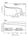
- a nickel cadmium battery's performance varies with temperature and depletes rapidly toward the end of its charge cycle, as shown in Fig. 3.
- the BQ2010 monitors battery temperature and charge cycle to improve performance.
- the BQ2010 adapts to battery temperature, rate of charge, rate of discharge, and self-discharge to provide meaningful charge information (i.e., more accurate and not merely approximated charge information) of various battery types across a wide range of operating conditions. As shown in Fig. 3, charge and discharge time are dependent upon temperature. Therefore, it is imperative that operating temperature be monitored in order to ascertain proper charge and discharge rates.
- a rechargeable battery slowly degrades over a period of time after which it has undergone multiple discharge and recharge cycles. Over the life of the battery, available charge capacity of a nickel cadmium battery declines as shown in Fig. 4. Circuit 18 recalibrates battery charge capacity in the course of a discharge cycle taking into account the relative age of the battery. Thereafter circuit 18 uses the recalibration values to provide accurate charge levels throughout the life of the battery. Circuit 18 uses the request to discharge in order to recalibrate both the fully discharge value and the fully charged value. This allows circuit 18 to accurately compute the charge and battery conditions. Recalibration of the battery is needed due to composition changes and temperature fluctuations within the battery material over the lifetime of the battery.
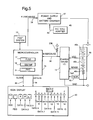
- Microcontroller 16 communicates with the charge gauge integrated circuit 18 with a variety of signals as shown in Fig. 5.
- the microcontroller 16 initiates all the serial communications to and from the charge gauge integrated circuit 18 by enabling Break signal via B_Sergauge signal 36. Break signal is driven onto B_Sergauge by protocol described below.
- the microcontroller 16 and charge gauge integrated circuit 18 transfer data on the bidirectional serial line via B-Sergauge signal 36.
- the bidirectional serial line B_Sergauge signal 36 allows the microcontroller 16 to read data from and write data to the charge gauge integrated circuit 18.
- the K_Discharge signal 38 allows the charge gauge integrated circuit 18 to fully discharge a battery before recharging.
- Sergauge signal is sent through the bidirectional data in/out pin of charge gauge circuit 18. Break signal is driven on the same line as sergauge data in/out, and K_discharge signal is driven by microcontroller 16 to the power supply in order to turn off AC wall adapter charge circuit.
- microcontroller 16 sends the following command/address codes to the charge gauge integrated circuit 18 via the bidirectional serial line B_Sergauge signal 36.
- charge gauge integrated circuit 18 In response to the address hex code 01 h, charge gauge integrated circuit 18 will transmit the following FLGS byte back to the microcontroller 16.
- the FLGS byte consists of:
- charge gauge integrated circuit 18 In response to the address hex code 02h, charge gauge integrated circuit 18 will transmit the following GG/TMP byte back to the microcontroller 16.
- the GG/TMP byte consists of:
- Bits 3-0 of the GG/TMP register contains the battery charge level as a percentage of full power.
- the GG/TMP register uses bits 3-0 to express binary numbers that represent the ten charge steps from 0 to 100%.
- Bits 7-4 of the GG/TMP register contains the battery temperature in degrees C.
- the GG/TMP register uses bits 7-4 to express binary numbers that represent the 10° C steps between negative 20° C and positive 70° C.
- PMC register 21 is a general purpose read/write register used by the BIOS to support power management functions in microcontroller 16. PMC register is written to and from the host system 10 BIOS and generally contains the firmware of microcontroller 16. The bit assignments of PMC register 21 are as follows:
- microcontroller 16 places the FLGS, GG/TMP, and PMC information into internal registers 17, 19 and 21, respectively.
- the microcontroller 16 will preferably update its internal registers by reading from the charge gauge integrated circuit 18 every one minute and writing the charge data to icon display 20. If the battery falls below the low battery setting, microcontroller 16 will update the internal registers every 0.5 minute and write charging information to ICON display 20.
- the low battery setting is defined by the user as prompted in power control menu 22. For example, if a user sets the low battery setting 28 at twenty percent of total charge, microcontroller 16 will read the battery data from the charge gauge integrated circuit 18 every one minutes until the battery level drops below twenty percent of total charge.
- microcontroller 16 will beep the speaker and then update the battery information every 0.5 minute.
- the programmable nature of the microcontroller allows a wide range of potential time intervals. For example, the user could set low battery to 30% allowing the speaker to beep and the charge gauge would be updated every 0.5 minute.
- the host computer 10 is not involved with updating microcontroller 18 until microcontroller 18 detects a fault condition from the FLGS bits. If the host detects a fault, the microcontroller then drives the interrupt line, H81NT, to interrupt host system 10 and obtain its attention.
- Prior art control methodologies often requires the host computer to update charge gauge icons which the present invention does not require. Periodic involvement of the host computer can cause program lockup of the host application. The present invention does not involve the host until a FLGS bit occurs and therefore the host computer 10 runs applications without having to slow down or possibly lock up.
- microcontroller 16 may display current status information on icon display 20.
- Icon display 20 is an LCD panel which is approximately 10 mm wide and 74 mm long. Icon display 20 is mounted on or near the keyboard.
- a CMOS LCD driver chip controls the display of the fourteen data segments on the icon display 20.
- a suitable CMOS LCD driver chip can be obtained from Microchip Technologies, Inc. of Chandler, AZ, as part no. AY0438-1.
- Microcontroller 16 communicates with the CMOS LCD driver chip via a Clock signal 42 and a Data_in signal 44.
- Data in signal 44 and Clock signal 42 are pin-out designated leads defined on the CMOS LCD driver chip.
- the first two data segments of icon display 20 depict the status of the hard disk drive (HDD), and the floppy disk drive (FDD). These two segments are driven from hardware control.
- the next three data segments display the status of the keyboard: caps lock (A), num lock (#), and scroll lock (curved arrow).
- the next eleven data segments represent the battery icon and ten fuel or charge meter icons which display the battery charge status.
- the charge meter icons range from empty to full in 10% charge steps. Thus, if six of the steps are displayed then 60% of battery charge remains.
- the data bit assignments are as follows:
- Power across power line 40 allow microcontroller 16 to fully charge while signal K_Discharge 38 allow microcontroller 16 to fully discharge, respectively, battery pack 46.
- Complete discharge e.g., 1.0 volt/cell for NICAD batteries
- the NICAD battery eventually loses its capacity to fully recharge. For example, if a battery is repeatedly recharged before reaching a low battery level, a three-hour battery may only last for one hour. A full discharge makes it possible to recharge a battery to nearly its original charge retention capacity.
- the microcontroller 16 When the microcontroller 16 obtains and stores battery data from the charge gauge integrated circuit 18 it will obtain the CI flag from the FLGS byte. An asserted CI flag notifies the microcontroller 16 to request a battery discharge cycle. If the charge gauge integrated circuit 18 asserts the CI flag, the microcontroller 16 will issue an interrupt signal to notify the BIOS of the need for a discharge cycle. The BIOS will check PMC register 21 and then will write to power control menu 22 that a discharge cycle is recommended and microcontroller 16 will blink the active battery icons. The user is given the option to disable a discharge cycle 30 in the power control menu 22. If the computer user has configured the power control menu 22 to allow a discharge, the BIOS will proceed with a discharge cycle.
- K_Discharge signal 38 will then be asserted.
- K_Discharge signal 38 turns off AC wall adapter 49 which allows battery pack 46 to discharge until battery 46 is equal to or less than very low voltage.
- Very low voltage is defined in the charge gauge integrated circuit 18 and is equal to EDV1 stored in FLGS register 17.
- a portable device's rechargeable battery pack 46 typically comprises a plurality of batteries. To meet space and power requirements, the batteries in the battery pack are arranged in cells. Each cell contains a battery that is serially connected. In the preferred embodiment, the battery pack consists of two serial cells 46a and 46b, each cell containing, for example, seven NICAD batteries. Battery pack 46 also includes a sense resistor 46c coupled between the negative terminal of the cells and ground. Battery pack 46 sends VCC and GND (power supplies) to circuit 18 as well as Sense signal indicative of the current charge stored within the battery pack. Furthermore, a thermacouple or thermistor 45 is thermall connected to battery pack 46 and sends electrical signals, Tmp, indicative of the current temperature of the cells.
- the very low voltage value may be set at 1.0 volt per cell.
- charge gauge integrated circuit 18 will drive the VLB signal to the BIOS and set the very low voltage flag (EDV1) within FLGS register 17.
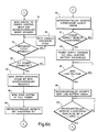
- Figs. 6a-6c illustrate a flowchart of one method for implementing programmable battery controller or charge gauge software.
- Associated software can be implemented in microcode and/or high level code, e.g., C-language.
- the flowchart shows how the microcontroller and system microprocessor interact to control and monitor battery charge status, temperature and discharge cycles.
- the computer is powered on or reset.
- the microcontroller executes its own program to monitor the battery.
- the microcontroller sends the commands to read the status flags and the battery data from the charge gauge integrated circuit.
- the charge gauge integrated circuit returns signals representing battery charge level, temperature level, and status flags to the microcontroller.
- step 58 through 60 the microcontroller times the duration until the next battery status update. If the battery charge level is greater than the low battery setting, the timer waits one minute until the next update. If the battery charge level is less than or equal to the low battery setting, then the timer waits for 0.5 minute until the next update.
- the microcontroller stores the battery data values in the microcontroller's internal registers.
- the microcontroller updates the battery charge level on the icon display.
- the microcontroller could compare the updated battery charge level with the previous battery charge level and only write to the icon display when the battery charge level changes.
- step 68 the microcontroller checks the discharge flag received from the charge gauge integrated circuit. If a discharge cycle is not necessary, the microcontroller continues to update battery status. If a discharge cycle is necessary, the microcontroller proceeds to step 70. In step 70 the microcontroller interrupts the system BIOS to request a discharge cycle.
- step 72 the system BIOS routines control when the discharge cycle is executed or begun.
- the BIOS which runs on the system microprocessor, communicates information to the computer user.
- step 72 the BIOS reads the internal registers from the microcontroller and checks in step 74 whether the discharge flag is asserted.
- step 74 the BIOS writes the power control menu and warns the computer user with an audio beep that a discharge cycle is recommended.
- step 76 the BIOS checks the power control menu to determine whether the computer user has enabled a discharge cycle. Then the BIOS will wait until the computer user enables the discharge cycle option, as shown in step 80.
- the BIOS will check that a power charger is connected to the computer in step 82. If a power charger is connected, The BIOS will then continue to step 84 where it will set the K_Discharge signal by writing to an internal register on the microcontroller. In step 86 the BIOS runs the system at maximum speed to quickly discharge the battery.
- the microcontroller executes the discharge cycle in steps 88 through 98.
- step 88 the microcontroller detects that the BIOS enables the discharge cycle by writing a logic one to DISCHG bit 0 of PMC register 21.
- the microcontroller correspondingly asserts its K_Discharge output signal in step 90.
- the K_Discharge signal is detected by the Power supply in step 92, and disables the battery charger in step 94.
- steps 96 and 98 the charge gauge integrated circuit monitors the battery and asserts the very low voltage flag when the battery voltage equals or falls below the chosen 1.0 volt per cell threshold (e.g., bit one of FLGS register 17).
- step 106 the microcontroller correspondingly disables its K_Discharge signal. Once the K_Discharge signal is no longer asserted, the Power supply enables the battery charger in step 108 to recharge the batteries.
- Fig. 7 shows a flowchart of the power control menu software.
- the BIOS runs on the system microprocessor and generates the power control menu software.
- the BIOS also communicates with microcontroller 10 via read cycles of host system 10 to obtain the battery status information and displays the information in power control menu 22.
- step 110 the computer requests battery status information when the user, for example, presses the Ctrl-Alt-P keys on the computer keyboard.
- the BIOS then reads the battery status information from the internal registers on the microcontroller PMC register21 in step 112.
- the power control menu then displays the battery charge, the battery temperature, and the user defined settings in step 114.
Abstract
Description
- This invention relates to a programmable battery controller and more particularly to a programmble apparatus, system and method for more accurately controlling and/or monitoring battery charge.
- Battery monitoring systems are commonly used to notify a portable computer user when a rechargeable battery needs recharging. Conventional battery monitoring systems often implement a software program that relies on a computer's hardware configuration and the power needed to run the components and peripherals. The software then monitors the usage of the components and peripherals to approximate the battery's drain rate and the remaining charge on the battery.
- Such software approximates the remaining battery charge based on the power specifications of components and peripherals. Based upon power specifications for particular components and the chosen battery discharge rate, the software then calculates approximately where the battery's charge level currently resides. Such approximations fail to take into account the variances of actual components. In addition, the computer user must adapt the software whenever a portable computer is reconfigured with different parts or new batteries, Software programs necessary to achieve many of these functions are often referred to as terminate and stay resident (TSR) programs. TSR programs typically require multiple host computer interface operations which can, and often do, cause the host computer to lock up periodically or cause the program not to be run.
- In an effort to overcome deficiencies of software approximation programs, more recent developments in charge monitoring devices have taken place. One such device monitors the voltage level of the rechargeable battery. An analog-to-digital converter may be employed to monitor the battery voltage throughout its operation. However, when a battery discharges during use, the voltage output generally reacts non-linearly. The non-linear discharge in the battery voltage may create false signals that a battery needs recharging when the battery, in fact, sti contains sufficient charge. Alternatively, non-linear discharge shows the battery as completely discharged even though adequate charge still remains. The false signals are read by the analog-to-digital con- verterwhich then outputs incorrect signals to the controller, and the controller prematurely charges the battery, thereby lessening the battery's capacity and lifetime.
- Typical battery voltage monitors often cannot and do not indicate when a full discharge has occurred and that recharge is now needed to maintain optimal battery performance. Nickel cadmium batteries are commonly used in portable computers. However, nickel cadmium batteries are susceptible to the memory effect--they might not recharge fully if they're not first completely discharged. For example, if a battery is repeatedly recharged before reaching a low battery level, a three-hour battery may only last for one hour. A full battery discharge helps eliminate the memory effect. Conventional charge monitoring devices often do not store non-linear discharge information. As a result the computer user must know of battery characteristics, and monitor battery usage to determine when a discharge is necessary and how long discharge is needed in order to prolong battery life.
- Some conventional monitoring devices use discrete components to measure the actual current drain on a battery. However such systems are bulky, do not provide flexibility, and do not exhibit accuracy. Battery discharge rates vary according to the batteries chemical composition, temperature, storage time, age of the battery, and load. Computer users find desirable battery monitoring systems which are not bulky and which can (i) determine when a discharge cycle is needed, (ii) determine an optimal discharge period, and (iii) perform the discharge and recharge cycles automatically under varying loads and operating temperatures.
- Other conventional monitoring devices place significant portions of the monitoring circuitry external to the battery operated device. The battery operated device stores battery status data until an external circuit is connected and evaluates the battery's status. Unfortunately such systems do not provide real time battery status updates. Connections must occur before battery--status can be read. Further, such systems require a user of a portable device to carry with him or her additional hardware circuitry and to connect that circuitry periodically to the battery operating device. Such constraints are cumbersome and make battery management and evaluation difficult.
- The problems outlined above are in large measure solved by the programmable battery controller described herein, and which provides a small accurate, real time, and flexible low power battery monitoring system that allows user input. The controller can accurately monitor temperature and charge characteristics as well as battery output variations over the life of the battery. Adjusting to battery output variations and executing full discharge cycles, the controller provides a controlling and monitoring system which can prolong battery life and enhance battery performance. Enhanced battery performance achieves more reliable battery operation, provides longer battery life from each battery charge, and allows smaller batteries to achieve the same system tasks. Accordingly, the battery monitoring system can be used in any programmable portable device, and allows for the design of smaller and lighter portable devices such as, for example, portable computers (i.e., notebooks, subnotebooks, laptops and/or palmtops) or any other host portable device having microprocessor- based operation.
- Furthermore, a programmable battery charger offers flexibility forfuture battery types and characteristics. Advances in rechargeable nickel cadmium (NICAD), lead-acid, nickel metal hydride (NMH), lithium, and carbon batteries provide a variety of new operating characteristics. Operating characteristics can include variations in charge current, storage duration, temperature degradation, battery age, and battery discharge rates. The programmable nature of the controller permits the design of battery monitoring parameters suitable to a particular battery's operating characteristics.
- A further feature of the controller is to allow a user to selectively change parameters. A user can input monitoring parameters to adapt to special circumstances, such as, for example, delaying a discharge cycle until the user manually initiates the discharge. Otherwise, once the parameters are set, discharge cycles can begin automatically without user interface. Also, the full programmability of the battery controller allows the presentation of battery charge data and battery status on future display devices and on present display devices such as on computer monitor cathode ray tubes (CRTs), icon displays (e.g., liquid crystal displays (LCDs), and light emitting diode (LED) indicators.
- The programmable controller further allows use of preset battery monitoring parameters. Thus, a user need not have any battery expertise or special battery knowledge. Battery monitoring and maintenance is transparent to the user. Thus, the user need not know the special characteristics of a battery nor need he or she know when discharge and recharge cycles are necessary. The controller automatically monitors and controls the battery charge based on the type of battery used, the temperature of the battery, the age of the battery, and the battery charge capacity.
- Still further, the controller allows the use of existing hardware on a portable computer system (or host system). Most portable computers have a keyboard, keyboard interface, and keyboard microcontroller to manage keyboard input. The software routines of the present invention use the pre-existing keyboard microcontroller hardware to help monitor battery parameters. Thus, the use of additional circuitry is not required by the host system. A reduction in battery monitoring hardware lessens space, weight and power requirements. In portable devices, weight and battery life provide competitive product advantages. Moreover, a reduction in battery monitoring hardware lessens manufacturing and maintenance costs. Other advantages of the present controller allow adaptation to other portable, battery driven host devices beyond keyboard entry microcontrollers. Such devices include microcontroller-based units which directly control peripherals such as pen-based input devices, mouse-based input devices, touch input devices, or scanning devices.
- Broadly speaking, we describe a programmable battery controller which uses hardware to monitor the actual charge drain and temperature of a rechargeable battery. The device includes a system microprocessor, a computer display, a keyboard interface gate array, a keyboard microcontroller, a charge gauge integrated circuit, and an icon display. Charge gauge software allows the keyboard microcontroller to monitor both the keyboard and the battery while also driving control signals to the host computer and battery charger. Further, the controller or charge gauging software allows a user to configure parameters to meet system needs. The battery controller system automatically determines when rechargeable battery discharge and charge cycles are needed. The charge controller system then notifies the user that a discharge is necessary to obtain maximum battery life. If enabled, the battery controller system wi execute discharge and charge cycles automatically without interfering with the user's current operation/application.
- The programmable controller also supports two display devices to transmit the battery status information to the computer user. One display device is a small LCD readout mounted on or near the computer keyboard called the icon display. The icon display shows the battery charge level as a fuel or charge meter with icons between full and empty. A battery icon, and ten other charge meter icons range from empty to full in 10% charge steps. Thus, if six of the charge meter icons are displayed, then 60% of battery charge remains. The controller system also has a capacity for, and can support, sixteen charge meter icons in order to display fractions of capacity similar to an automobile fuel guage (e.g., 1/4, 1/2, 3/4, etc.).
- The second display device is a conventional computer display. The charge gauge software presents the battery temperature, charge status, and user configured parameters in a menu format. The computer user presses a combination of keys (e.g., control-alt-P) on the computer keyboard to bring up the power control menu. Once in this menu, the computer user can select options and obtain battery status information.
- We also describe a method for monitoring a computer battery which includes such a battery charge gauge system. In the method of monitoring the computer battery, charge gauge software follows preset battery monitoring parameters. This allows the user to interact with the computer user to alter the battery monitoring parameters as desired. The battery monitoring parameters include items such as the low level battery threshold, battery warning messages, discharge cycle enable, and low battery audio warnings. Based on the battery monitoring parameters, the charge gauge software continuously updates battery data such as charge levels and battery pack internal temperature.
- In the accompanying drawings, by way of example only:
- Fig. 1 is a block diagram of a programmable battery controller embodying the present invention;
- Fig. 2 is a user interactive power control menu configured upon a computer display;
- Fig. 3 is a graph of battery voltage capacity versus battery discharge time at various temperatures;
- Fig. 4 is a graph of battery charge capacity versus battery charge cycle during the life of a battery;
- Fig. 5 is a block diagram of a microcontroller, charge gauge circuit and icon display embodying the present invention;
- Figs. 6a, 6b and 6c are flowcharts that depict one technique for controlling and monitoring a rechargeable battery pack;
- Fig. 7 is a flowchart that depicts one technique for controlling the power control menu.
- Turning now to the drawings, Fig. 1 illustrates a block diagram of a
programmable battery controller 8 or battery charge gauge system. The battery controller orcharge gauge system 8 includes asystem microprocessor 10, a computer monitor ordisplay 12, akeyboard gate array 14, amicrocontroller 16, a charge gauge integratedcircuit 18, and anicon display 20.System microprocessor 10 runs charge gauge software necessary to interface tomicrocontroller 16 viakeyboard gate array 14. - Software placed within
microcontroller 16 monitors the charge gauge integratedcircuit 18 and obtains battery data such as charge, temperature, and battery status information.Microcontroller 16 communicates the battery information to thesystem microprocessor 10 which displays the battery charge, temperature and battery status information to thecomputer display 12. In addition to, or in lieu of, thecomputer display 12, anicon display 20 may be used to indicate battery-charge status.Icon display 20 includes a small liquid crystal display (LCD) readout mounted on or near the computer keyboard. LCD readout is active independent ofcomputer display 12. -
System microprocessor 10 acts as a central processing unit that executes an operating system. The operating system is an integrated collection of supervisory programs and subroutines that control the execution of the computer programs and performs special system functions. One such special function of the operating system is to control the basic input and output of the charge gauge system. The basic input and output or "BIOS" routines work closely with the hardware to support the transfer of information between elements of the system. The BIOS routines also communicate withmicrocontroller 16, by reading data from and writing data to the internal registers on themicrocontroller 16.Microcontroller 16 communicates with the BIOS by asserting an interrupt. Themicrocontroller 16 executes its own programs and only interrupts thesystem microprocessor 10 when some action needs to be taken. During a microcontroller interrupt, the BIOS will stop the present program running on thesystem microprocessor 10 and check the status of themicrocontroller 16 by reading data from the microcontroller's internal registers viakeyboard gate array 14. Depending on the status of the microcontroller's internal registers, the BIOS will warn the computer user about a low battery charge level, when a discharge cycle request is made, or when a battery is replaced. - The power management BIOS routine incorporates charge gauge software and a
power control menu 22, as shown in Fig. 2.Power control menu 22 allows a user to define the power monitoring characteristics. A user enters thepower control menu 22 by pressing a series of keys on the keyboard. In the preferred exemplary embodiment the user presses Cntl-Alt-P on the computer keyboard and thepower control menu 22 is then displayed on thecomputer display 12. The user can then interacts with and/or control the battery by responding, via the keyboard, to themenu 22 prompts. - The
power control menu 22 displays battery data such as thecurrent battery charge 24 remaining on the battery and thecurrent battery temperature 26.Battery charge 24 andtemperature 26 are expressed as a bar gauge indicator as shown.Power control menu 22 also displays battery monitor parameters such as low battery setting 28, thedischarge cycle 30, and lowbattery audio warning 32. "Maintenance discharge requested" and "discharge cycle permitted" are preferrably displayed only whencharge guage circuit 18 has requested a discharge cycle. The user defines the battery monitoring parameters by altering the various settings. The charge gauge software will utilize the battery monitoring parameters to monitor the computer's battery. For example, the low battery level setting defines the charge level for a low battery warning. If the user changes the low battery level setting 28, from 10% to 20%, the computer will warn the user to recharge the battery when 20% of the charge remains. Likewise, the user can enable automatic discharge cycle by changingsettings 30 from "no" to "yes". Automatic discharge will occur periodically without user interaction. Low battery audio warning 32 can be enabled to audibly warn the user of a low battery. -
Host system microprocessor 10 is commonly configured by those skilled in this art to run a standard system BIOS providing all standard BIOS routines including charge gauge software routines.System microprocessor 10 may include any AT/XT IBMo-compatible microprocessor such as a 386, 486 or derivative microprocessor architecture manufactured by, e.g., Intel Corp. of Santa Clara, CA, or Advanced Micro Devices, Inc. of Sunny- vale, CA.Microprocessor 10 preferably operates at or near 3.3 V. It is important to note, however, that other microprocessors and operating voltage levels may be used provided they are capable of running the BIOS routines herein described. - BIOS running on
system microprocessor 10 communicates to themicrocontroller 16 via thekeyboard gate array 14. A bidirectional bus connectshost system 10 tomicrocontroller 16 via a universal peripheral interface controller. A suitable peripheral controller can be obtained from Intel Corp. of Santa Clara, CA, part no. 8742. Peripheral controller (not shown) allows the user to control a peripheral such asmicrontroller 16. Peripheral controller includes internal status and data registers along with and ROM, RAM, I/O timer and clock control to allow the controller to read/write information betweenhost microprocessor 10 andmicrontroller 16 as shown. - Keyboard gate array emulates the keyboard controller commonly used in AT/XT and/or PS/2 compatible personal computers. A suitable
keyboard gate array 14 may be obtained from Western Digital Corporation of Irvine, CA, part no. WD7635LV. However, it is understood that the battery charge gauge system may employ other circuits to emulate the keyboard controller. The WD7635LVkeyboard gate array 14 andmicrocontroller 16 provides keyboard compatibility, reduces power consumption, increases battery life, and minimizes chip count. Asuitable microcontroller 16 can be obtained from Hitachi Corp., San Jose, CA, part no. H8/330 keyboard controller. It is important to note thatgate array 14 andmicrocontroller 16 can be combined on a single monolithic chip is desired. The single chip can be obtained from Hitachi Corp. of San Jose, CA, part no. H8/3332. - It is understood that, in general, a microcontroller operates similar to a microprocessor in that a microcontroller has a central processor, memory and input/output ports. However, microcontroller design enhances real-time, hardware-intensive applications such as keyboard encoding. As described above, in the preferred exemplary embodiment,
microcontroller 16 may be obtained from Hitachi Corp., part no. H8/330 keyboard controller; however, other general purpose microcontrollers with adequate internal registers and communication ports may also be used. Portions of the charge gauge software reside in the firmware ofmicrocontroller 16. The programmability ofmicrocontroller 16 firmware reduces chip count and provides flexibility in adaptation to future configurations. - Charge gauge integrated
circuit 18 monitors the battery charge level via a battery charge sensor. The battery charge sensor consists of asense resistor 46c of common design connected to the battery's negative battery terminal and ground to determine charge and discharge current activity (see Fig. 5). Charge gauge integratedcircuit 18 not only monitors status ofsense resistor 46c but also monitors battery temperature via a thermistor45 connected tobattery 46. The thermistor placed into the battery pack includes a thermal resistor of common design that changes resistance in relation to the temperature. Charge gauge integratedcircuit 18 is preferably implemented using part no. BQ2010 integrated circuit manufactured by Benchmarq Microelectronics, Dallas, TX. However, the battery charge gauge system may use other circuits with similar measurement capabilities. The BQ2010 combines battery-monitoring, management, discharging and charging functions on one integrated circuit. The BQ2010 chip gauges battery charge consumption and works with the following rechargeable batteries: NICAD, NMH, lead-acid, lithium, and carbon batteries. - The capability of reporting on remaining battery charge is especially important with all rechargeable batteries such as nickel cadmium batteries. A nickel cadmium battery's performance varies with temperature and depletes rapidly toward the end of its charge cycle, as shown in Fig. 3. The BQ2010 monitors battery temperature and charge cycle to improve performance. The BQ2010 adapts to battery temperature, rate of charge, rate of discharge, and self-discharge to provide meaningful charge information (i.e., more accurate and not merely approximated charge information) of various battery types across a wide range of operating conditions. As shown in Fig. 3, charge and discharge time are dependent upon temperature. Therefore, it is imperative that operating temperature be monitored in order to ascertain proper charge and discharge rates.
- A rechargeable battery slowly degrades over a period of time after which it has undergone multiple discharge and recharge cycles. Over the life of the battery, available charge capacity of a nickel cadmium battery declines as shown in Fig. 4.
Circuit 18 recalibrates battery charge capacity in the course of a discharge cycle taking into account the relative age of the battery. Thereaftercircuit 18 uses the recalibration values to provide accurate charge levels throughout the life of the battery.Circuit 18 uses the request to discharge in order to recalibrate both the fully discharge value and the fully charged value. This allowscircuit 18 to accurately compute the charge and battery conditions. Recalibration of the battery is needed due to composition changes and temperature fluctuations within the battery material over the lifetime of the battery. Battery life, temperature, number of charge/discharge cycles all vary as a function of time, thereby necessitating periodic recalibration. It is therefore important to monitor the battery's relative age or charge capacity in order to accurately determine proper discharge and/or charge rate and cycle time. -
Microcontroller 16 communicates with the charge gauge integratedcircuit 18 with a variety of signals as shown in Fig. 5. Themicrocontroller 16 initiates all the serial communications to and from the charge gauge integratedcircuit 18 by enabling Break signal viaB_Sergauge signal 36. Break signal is driven onto B_Sergauge by protocol described below. Themicrocontroller 16 and charge gauge integratedcircuit 18 transfer data on the bidirectional serial line via B-Sergauge signal 36. The bidirectional serialline B_Sergauge signal 36 allows themicrocontroller 16 to read data from and write data to the charge gauge integratedcircuit 18. TheK_Discharge signal 38 allows the charge gauge integratedcircuit 18 to fully discharge a battery before recharging. Sergauge signal is sent through the bidirectional data in/out pin ofcharge gauge circuit 18. Break signal is driven on the same line as sergauge data in/out, and K_discharge signal is driven bymicrocontroller 16 to the power supply in order to turn off AC wall adapter charge circuit. - To read information,
microcontroller 16 sends the following command/address codes to the charge gauge integratedcircuit 18 via the bidirectional serialline B_Sergauge signal 36.
- In response to the address hex code 01 h, charge gauge integrated
circuit 18 will transmit the following FLGS byte back to themicrocontroller 16. The FLGS byte consists of:
- In response to the address hex code 02h, charge gauge integrated
circuit 18 will transmit the following GG/TMP byte back to themicrocontroller 16. The GG/TMP byte consists of:
- Bits 3-0 of the GG/TMP register contains the battery charge level as a percentage of full power. The GG/TMP register uses bits 3-0 to express binary numbers that represent the ten charge steps from 0 to 100%. Bits 7-4 of the GG/TMP register contains the battery temperature in degrees C. The GG/TMP register uses bits 7-4 to express binary numbers that represent the 10° C steps between negative 20° C and positive 70° C.
- FLGS byte is written to and read from FLGS register 17 contained within
microcontroller 16. Likewise, GG/TMP is written to and read from GG/TMP register 19 contained withinmicrocontroller 16. Yet another register, denoted asPMC register 21, is contained withinmicrocontroller 16. PMC register is a general purpose read/write register used by the BIOS to support power management functions inmicrocontroller 16. PMC register is written to and from thehost system 10 BIOS and generally contains the firmware ofmicrocontroller 16. The bit assignments of PMC register 21 are as follows:
- As described above,
microcontroller 16 places the FLGS, GG/TMP, and PMC information intointernal registers microcontroller 16 will preferably update its internal registers by reading from the charge gauge integratedcircuit 18 every one minute and writing the charge data toicon display 20. If the battery falls below the low battery setting,microcontroller 16 will update the internal registers every 0.5 minute and write charging information toICON display 20. The low battery setting is defined by the user as prompted inpower control menu 22. For example, if a user sets the low battery setting 28 at twenty percent of total charge,microcontroller 16 will read the battery data from the charge gauge integratedcircuit 18 every one minutes until the battery level drops below twenty percent of total charge. Once the battery drops below twenty percent,microcontroller 16 will beep the speaker and then update the battery information every 0.5 minute. Although the preferred invention updates the battery data on one minute and 0.5 minute intervals, the programmable nature of the microcontroller allows a wide range of potential time intervals. For example, the user could set low battery to 30% allowing the speaker to beep and the charge gauge would be updated every 0.5 minute. Thehost computer 10 is not involved with updatingmicrocontroller 18 untilmicrocontroller 18 detects a fault condition from the FLGS bits. If the host detects a fault, the microcontroller then drives the interrupt line, H81NT, to interrupthost system 10 and obtain its attention. Prior art control methodologies often requires the host computer to update charge gauge icons which the present invention does not require. Periodic involvement of the host computer can cause program lockup of the host application. The present invention does not involve the host until a FLGS bit occurs and therefore thehost computer 10 runs applications without having to slow down or possibly lock up. - In addition to, or in lieu of computer display control menu,
microcontroller 16 may display current status information onicon display 20.Icon display 20 is an LCD panel which is approximately 10 mm wide and 74 mm long.Icon display 20 is mounted on or near the keyboard. A CMOS LCD driver chip controls the display of the fourteen data segments on theicon display 20. A suitable CMOS LCD driver chip can be obtained from Microchip Technologies, Inc. of Chandler, AZ, as part no. AY0438-1. -
Microcontroller 16 communicates with the CMOS LCD driver chip via aClock signal 42 and aData_in signal 44. Data insignal 44 andClock signal 42 are pin-out designated leads defined on the CMOS LCD driver chip. The first two data segments oficon display 20 depict the status of the hard disk drive (HDD), and the floppy disk drive (FDD). These two segments are driven from hardware control. The next three data segments display the status of the keyboard: caps lock (A), num lock (#), and scroll lock (curved arrow). The next eleven data segments represent the battery icon and ten fuel or charge meter icons which display the battery charge status. The charge meter icons range from empty to full in 10% charge steps. Thus, if six of the steps are displayed then 60% of battery charge remains. The data bit assignments are as follows:
- Thus, a computer user can quickly see the status of various peripherals and how much battery charge exists by looking at the charge gauge on
icon display 20. - Power across
power line 40 allowmicrocontroller 16 to fully charge whilesignal K_Discharge 38 allowmicrocontroller 16 to fully discharge, respectively,battery pack 46. Complete discharge (e.g., 1.0 volt/cell for NICAD batteries) is periodically achieved in order to subsequently allow optimal recharging. If a computer's NICAD battery is repeatedly recharged before full discharge, the NICAD battery eventually loses its capacity to fully recharge. For example, if a battery is repeatedly recharged before reaching a low battery level, a three-hour battery may only last for one hour. A full discharge makes it possible to recharge a battery to nearly its original charge retention capacity. - When the
microcontroller 16 obtains and stores battery data from the charge gauge integratedcircuit 18 it will obtain the CI flag from the FLGS byte. An asserted CI flag notifies themicrocontroller 16 to request a battery discharge cycle. If the charge gauge integratedcircuit 18 asserts the CI flag, themicrocontroller 16 will issue an interrupt signal to notify the BIOS of the need for a discharge cycle. The BIOS will checkPMC register 21 and then will write topower control menu 22 that a discharge cycle is recommended andmicrocontroller 16 will blink the active battery icons. The user is given the option to disable adischarge cycle 30 in thepower control menu 22. If the computer user has configured thepower control menu 22 to allow a discharge, the BIOS will proceed with a discharge cycle. There are times when the computer user will not have time for a discharge cycle. Thus, if the computer user needs to give a presentation, needs to complete a certain job, or cannot immediately plug in a chargingpower supply 47 to anAC wall adapter 49, the user can prompt the BIOS to delay execution of the discharge cycle until which time the user is ready. - Once the computer user enables the
discharge cycle 30 on thepower control menu 22, and a charging power supply such as anAC adaptor 49 is connected to thecomputer microcontroller 16,K_Discharge signal 38 will then be asserted.K_Discharge signal 38 turns offAC wall adapter 49 which allowsbattery pack 46 to discharge untilbattery 46 is equal to or less than very low voltage. Very low voltage is defined in the charge gauge integratedcircuit 18 and is equal to EDV1 stored inFLGS register 17. - A portable device's
rechargeable battery pack 46 typically comprises a plurality of batteries. To meet space and power requirements, the batteries in the battery pack are arranged in cells. Each cell contains a battery that is serially connected. In the preferred embodiment, the battery pack consists of twoserial cells Battery pack 46 also includes asense resistor 46c coupled between the negative terminal of the cells and ground.Battery pack 46 sends VCC and GND (power supplies) tocircuit 18 as well as Sense signal indicative of the current charge stored within the battery pack. Furthermore, a thermacouple orthermistor 45 is thermall connected tobattery pack 46 and sends electrical signals, Tmp, indicative of the current temperature of the cells. The very low voltage value may be set at 1.0 volt per cell. When the battery pack discharges to 1.0 volt/cell, charge gauge integratedcircuit 18 will drive the VLB signal to the BIOS and set the very low voltage flag (EDV1) withinFLGS register 17. The BIOS will then command a display of the request to dischargemessage 30 inpower menu 22 and beep the speaker. If the user selects "yes" to enable discharge cycle, then the BIOS will write logic one to PMC register 21 causingmicrocontroller 16 to drive K_Discharge. After completion of the discharge cycle,microcontroller 16 senses FLGS bit =logic 1, and therefore, resets K_Discharge to become diabled and thepower supply 47 will recharge the battery pack viaAC wall adapter 49. - Figs. 6a-6c illustrate a flowchart of one method for implementing programmable battery controller or charge gauge software. Associated software can be implemented in microcode and/or high level code, e.g., C-language. The flowchart shows how the microcontroller and system microprocessor interact to control and monitor battery charge status, temperature and discharge cycles. In
step 50, the computer is powered on or reset. Insteps 52 through 56, the microcontroller executes its own program to monitor the battery. The microcontroller sends the commands to read the status flags and the battery data from the charge gauge integrated circuit. The charge gauge integrated circuit returns signals representing battery charge level, temperature level, and status flags to the microcontroller. Instep 58 through 60 the microcontroller times the duration until the next battery status update. If the battery charge level is greater than the low battery setting, the timer waits one minute until the next update. If the battery charge level is less than or equal to the low battery setting, then the timer waits for 0.5 minute until the next update. - In
steps step 66 the microcontroller updates the battery charge level on the icon display. In another preferred embodiment, the microcontroller could compare the updated battery charge level with the previous battery charge level and only write to the icon display when the battery charge level changes. - In
step 68 the microcontroller checks the discharge flag received from the charge gauge integrated circuit. If a discharge cycle is not necessary, the microcontroller continues to update battery status. If a discharge cycle is necessary, the microcontroller proceeds to step 70. Instep 70 the microcontroller interrupts the system BIOS to request a discharge cycle. - In
steps 72 through 86 the system BIOS routines control when the discharge cycle is executed or begun. The BIOS, which runs on the system microprocessor, communicates information to the computer user. Instep 72 the BIOS reads the internal registers from the microcontroller and checks instep 74 whether the discharge flag is asserted. Instep 74 the BIOS writes the power control menu and warns the computer user with an audio beep that a discharge cycle is recommended. Instep 76 the BIOS checks the power control menu to determine whether the computer user has enabled a discharge cycle. Then the BIOS will wait until the computer user enables the discharge cycle option, as shown instep 80. - Once the computer user enables the discharge cycle option, the BIOS will check that a power charger is connected to the computer in
step 82. If a power charger is connected, The BIOS will then continue to step 84 where it will set the K_Discharge signal by writing to an internal register on the microcontroller. Instep 86 the BIOS runs the system at maximum speed to quickly discharge the battery. - The microcontroller executes the discharge cycle in
steps 88 through 98. Instep 88 the microcontroller detects that the BIOS enables the discharge cycle by writing a logic one toDISCHG bit 0 ofPMC register 21. The microcontroller correspondingly asserts its K_Discharge output signal instep 90. The K_Discharge signal is detected by the Power supply instep 92, and disables the battery charger instep 94. Insteps - In
step 100 the microcontroller detectsFLGS bit 1 =logic 1 and signals completion of the discharge cycle by writing to an internal register on the microcontrollerPMC register bit 0 tologic 0. Instep 106 the microcontroller correspondingly disables its K_Discharge signal. Once the K_Discharge signal is no longer asserted, the Power supply enables the battery charger instep 108 to recharge the batteries. - Fig. 7 shows a flowchart of the power control menu software. The BIOS runs on the system microprocessor and generates the power control menu software. The BIOS also communicates with
microcontroller 10 via read cycles ofhost system 10 to obtain the battery status information and displays the information inpower control menu 22. - In
step 110 the computer requests battery status information when the user, for example, presses the Ctrl-Alt-P keys on the computer keyboard. The BIOS then reads the battery status information from the internal registers on the microcontroller PMC register21 instep 112. The power control menu then displays the battery charge, the battery temperature, and the user defined settings instep 114. - It is to be understood that the form of the invention shown and described is to be taken as an exemplary preferred embodiment. Furthermore, it will be appreciated by those skilled in the art having the benefit of the foregoing disclosure and description that this invention is capable of variations in the size, shape, materials, components, circuit elements, wiring connections, and software without departing from the spirit of the invention.
Claims (19)
and
Applications Claiming Priority (2)
| Application Number | Priority Date | Filing Date | Title |
|---|---|---|---|
| US19858 | 1987-02-27 | ||
| US08/019,858 US5459671A (en) | 1993-02-19 | 1993-02-19 | Programmable battery controller |
Publications (2)
| Publication Number | Publication Date |
|---|---|
| EP0612134A2 true EP0612134A2 (en) | 1994-08-24 |
| EP0612134A3 EP0612134A3 (en) | 1995-09-20 |
Family
ID=21795410
Family Applications (1)
| Application Number | Title | Priority Date | Filing Date |
|---|---|---|---|
| EP94300759A Withdrawn EP0612134A3 (en) | 1993-02-19 | 1994-02-02 | Programmable battery controllers. |
Country Status (3)
| Country | Link |
|---|---|
| US (1) | US5459671A (en) |
| EP (1) | EP0612134A3 (en) |
| JP (1) | JPH06245399A (en) |
Cited By (4)
| Publication number | Priority date | Publication date | Assignee | Title |
|---|---|---|---|---|
| FR2724731A1 (en) * | 1994-09-16 | 1996-03-22 | Emhart Glass Mach Invest | CONTAINER INSPECTION MACHINE HAVING SEQUENTIAL ACCESS COMPUTER ALIGNMENT GAUGES |
| GB2327542A (en) * | 1997-07-17 | 1999-01-27 | Nokia Mobile Phones Ltd | Battery deep discharge alert |
| WO2005057752A2 (en) | 2003-12-05 | 2005-06-23 | Motorola, Inc. | Method and apparatus for use with a portable power source |
| WO2018057233A1 (en) * | 2016-09-26 | 2018-03-29 | Siemens Industry, Inc. | Configurable remote battery monitor |
Families Citing this family (82)
| Publication number | Priority date | Publication date | Assignee | Title |
|---|---|---|---|---|
| US5397991A (en) * | 1988-07-13 | 1995-03-14 | Electronic Development Inc. | Multi-battery charging system for reduced fuel consumption and emissions in automotive vehicles |
| US5602459A (en) | 1988-07-13 | 1997-02-11 | Electronic Development Inc. | Fuel saving multi-battery charging system and method |
| US5563496A (en) * | 1990-12-11 | 1996-10-08 | Span, Inc. | Battery monitoring and charging control unit |
| JPH0785893A (en) * | 1993-09-17 | 1995-03-31 | Sony Corp | Method for charging battery |
| US6274950B1 (en) * | 1994-03-03 | 2001-08-14 | American Power Conversion | Battery communication system |
| US5606242A (en) * | 1994-10-04 | 1997-02-25 | Duracell, Inc. | Smart battery algorithm for reporting battery parameters to an external device |
| US5600230A (en) * | 1994-12-15 | 1997-02-04 | Intel Corporation | Smart battery providing programmable remaining capacity and run-time alarms based on battery-specific characteristics |
| US5629605A (en) * | 1995-01-24 | 1997-05-13 | Dell Usa, L.P. | Pulsewidth modulated visual indicator for battery status |
| JPH0951303A (en) * | 1995-08-08 | 1997-02-18 | Kokusai Electric Co Ltd | Card-type radio receiver |
| US5841996A (en) * | 1995-10-13 | 1998-11-24 | Microchip Technology Incorporated | Serial communication interface system having programmable microcontroller for use in a battery pack |
| US5826958A (en) * | 1995-12-15 | 1998-10-27 | Ora Electronics, Inc. | Apparatus for automatically conditioning rechargeable batteries |
| US5764034A (en) * | 1996-04-10 | 1998-06-09 | Baxter International Inc. | Battery gauge for a battery operated infusion pump |
| US5751134A (en) * | 1996-05-16 | 1998-05-12 | Itronix Corporation | Gas gauging system and method for monitoring battery capacity for battery powered electronic devices |
| WO1998002933A1 (en) * | 1996-07-17 | 1998-01-22 | Duracell Inc. | Battery operating system |
| US5714870A (en) * | 1996-12-18 | 1998-02-03 | Intel Corporation | Method for measuring suspend-time power consumption in a battery-powered electronic device |
| US5895440A (en) * | 1996-12-23 | 1999-04-20 | Cruising Equipment Company, Inc. | Battery monitor and cycle status indicator |
| JP3013825B2 (en) * | 1997-12-02 | 2000-02-28 | 日本電気株式会社 | Information terminal device, input / output control method, and recording medium |
| US6014141A (en) * | 1997-03-25 | 2000-01-11 | Micron Electronics, Inc. | Method and apparatus for selectively displaying a parameter in a separate status panel |
| US6025695A (en) * | 1997-07-09 | 2000-02-15 | Friel; Daniel D. | Battery operating system |
| US6094624A (en) * | 1997-08-19 | 2000-07-25 | Chao; Nathan | Electronic test facility |
| DE19740559C1 (en) | 1997-09-15 | 1999-04-08 | Siemens Ag | Method and device for determining the charging current of an accumulator |
| EP0921620B1 (en) * | 1997-12-03 | 2005-07-20 | Matsushita Electric Industrial Co., Ltd. | Method for temperature dependent charging of a back-up power source which is subject to self-discharging |
| US6218806B1 (en) | 1998-06-03 | 2001-04-17 | Black & Decker Inc. | Method and apparatus for obtaining product use information |
| KR100490393B1 (en) | 1998-10-09 | 2005-09-02 | 삼성전자주식회사 | System and method for automatic notification of battery replacement time |
| US6177780B1 (en) | 1998-12-09 | 2001-01-23 | Veritas Dgc, Inc. | Battery charger with improved reliability |
| US6014013A (en) * | 1998-12-16 | 2000-01-11 | Space Systems/Loral, Inc. | Battery charge management architecture |
| JP2000214965A (en) * | 1999-01-25 | 2000-08-04 | Toshiba Corp | Computer system and method for managing battery event |
| US6169384B1 (en) * | 1999-04-19 | 2001-01-02 | Packard Bell Nec Inc. | Power source system for portable electronic devices |
| KR100517546B1 (en) * | 1999-07-16 | 2005-09-28 | 삼성전자주식회사 | Portable computer displaying post code on led indicator |
| AU2001290371A1 (en) * | 2000-09-04 | 2002-03-22 | Invensys Energy Systems (Nz) Limited | Battery monitoring |
| JP2002320341A (en) * | 2001-02-14 | 2002-10-31 | Sony Corp | Charge/discharge device and method therefor, power supply device and method therefor, power supply system and method therefor, program storage medium, and program thereof |
| US6833792B1 (en) * | 2001-03-30 | 2004-12-21 | Bellsouth Intellectual Property Corporation | Battery capacity indicator in a portable computing device |
| US6879259B1 (en) * | 2001-03-30 | 2005-04-12 | Bellsouth Intellectual Property Corporation | Battery voltage indicator in a portable computing device |
| DE10235008B4 (en) * | 2001-08-03 | 2005-02-24 | Yazaki Corp. | Method and unit for calculating the degree of degradation for a battery |
| US6677729B2 (en) * | 2001-08-03 | 2004-01-13 | Yazaki Corporation | Method and unit for computing voltage drop divided along factors for battery |
| KR100724833B1 (en) * | 2001-09-04 | 2007-06-04 | 엘지전자 주식회사 | Method for saving the data based on power source |
| CN100379078C (en) | 2001-10-11 | 2008-04-02 | 迪诺佛研究有限公司 | Digital battery |
| US6983212B2 (en) | 2001-11-27 | 2006-01-03 | American Power Conversion Corporation | Battery management system and method |
| WO2003060833A1 (en) * | 2002-01-11 | 2003-07-24 | Hill-Rom Services, Inc. | Battery recharger for personnel locating system badges |
| US6822425B2 (en) * | 2002-01-25 | 2004-11-23 | Vector Products, Inc. | High frequency battery charger and method of operating same |
| JP4294966B2 (en) * | 2002-02-18 | 2009-07-15 | シチズンホールディングス株式会社 | Electronic timepiece, secondary battery storage state display method, secondary battery storage state display program, and information processing terminal device |
| US6753625B2 (en) * | 2002-03-28 | 2004-06-22 | International Business Machines Corporation | Method and apparatus for implementing programmable battery shut off |
| US7104684B2 (en) * | 2002-11-29 | 2006-09-12 | Sigmatel, Inc. | On-chip digital thermometer to sense and measure device temperatures |
| JP3669702B2 (en) * | 2003-02-25 | 2005-07-13 | 松下電器産業株式会社 | Application program prediction method and mobile terminal |
| JP3935099B2 (en) * | 2003-04-15 | 2007-06-20 | 株式会社デンソー | Internal state detection system for power storage device for vehicle |
| US9259584B2 (en) | 2003-10-02 | 2016-02-16 | Medtronic, Inc. | External unit for implantable medical device coupled by cord |
| WO2005032658A1 (en) * | 2003-10-02 | 2005-04-14 | Medtronic, Inc. | User interface for external charger for implantable medical device |
| US7528579B2 (en) | 2003-10-23 | 2009-05-05 | Schumacher Electric Corporation | System and method for charging batteries |
| US7212006B2 (en) * | 2004-07-02 | 2007-05-01 | Bppower, Inc. | Method and apparatus for monitoring the condition of a battery by measuring its internal resistance |
| US7746242B2 (en) * | 2004-07-21 | 2010-06-29 | Honeywell International Inc. | Low battery indicator |
| US7417405B2 (en) * | 2004-10-04 | 2008-08-26 | Black & Decker Inc. | Battery monitoring arrangement having an integrated circuit with logic controller in a battery pack |
| US7782020B1 (en) * | 2005-01-14 | 2010-08-24 | Network Appliance, Inc. | Operating a non-volatile memory charger |
| US7386403B2 (en) * | 2005-03-30 | 2008-06-10 | Inventec Corporation | Method and system for charging management |
| US8234482B2 (en) * | 2005-10-13 | 2012-07-31 | Google Inc. | Universal embedded controller for freeing CPU from operations of peripheral subsystem units with table of functions including an instruction specifying battery controller select protocol |
| US20070194791A1 (en) | 2006-02-17 | 2007-08-23 | Bppower Inc. | Method and apparatus for monitoring the condition of a battery by measuring its internal resistance |
| US7646167B2 (en) * | 2006-04-26 | 2010-01-12 | Technuity, Inc. | System for updating programmable batteries |
| US7750598B2 (en) * | 2006-10-05 | 2010-07-06 | Eveready Battery Company, Inc. | Battery charger user interface |
| CN101334452B (en) * | 2007-06-29 | 2011-06-08 | 鸿富锦精密工业(深圳)有限公司 | Battery tester |
| US7928735B2 (en) | 2007-07-23 | 2011-04-19 | Yung-Sheng Huang | Battery performance monitor |
| US7944182B2 (en) * | 2007-08-03 | 2011-05-17 | American Power Conversion Corporation | Adjustable battery charger for UPS |
| TW200906566A (en) * | 2007-08-07 | 2009-02-16 | Nat Energy Technology Co Ltd | Electric tool |
| US9160200B2 (en) * | 2007-12-28 | 2015-10-13 | At&T Intellectual Property I, L.P. | Configurable battery end-of-life indicator |
| US8120363B2 (en) | 2008-11-24 | 2012-02-21 | Cummins Power Generation Ip, Inc. | Voltage drop compensation for an electric power storage device charging system |
| US8581554B2 (en) * | 2009-07-10 | 2013-11-12 | Schneider Electric It Corporation | Battery charging method and apparatus |
| KR101126928B1 (en) * | 2009-07-13 | 2012-03-20 | 삼성에스디아이 주식회사 | Battery pack including remain capccity display device |
| US20110193518A1 (en) * | 2010-02-10 | 2011-08-11 | James Wright | Battery override |
| US20110205048A1 (en) * | 2010-02-22 | 2011-08-25 | EV Instruments, LLC | Computer software and apparatus for control and monitoring of electronic systems |
| US9065292B2 (en) | 2010-08-23 | 2015-06-23 | California Institute Of Technology | Methods and systems for charging electrochemical cells |
| JP5565273B2 (en) * | 2010-10-29 | 2014-08-06 | 株式会社豊田自動織機 | Industrial vehicle |
| US20120210150A1 (en) * | 2011-02-10 | 2012-08-16 | Alcatel-Lucent Usa Inc. | Method And Apparatus Of Smart Power Management For Mobile Communication Terminals |
| US20150000651A1 (en) * | 2012-01-16 | 2015-01-01 | Honeywell International Inc. | Accurate determination of remaining time to battery empty in a powered air purifying respirator |
| US9195286B2 (en) * | 2012-03-26 | 2015-11-24 | Mediatek Inc. | Method for performing power consumption control, and associated apparatus |
| US20140107853A1 (en) * | 2012-06-26 | 2014-04-17 | Black & Decker Inc. | System for enhancing power tools |
| FR3006812A1 (en) | 2013-06-06 | 2014-12-12 | St Microelectronics Tours Sas | MANAGING THE LIFETIME OF A BATTERY |
| GB2518128B (en) * | 2013-06-20 | 2021-02-10 | Nokia Technologies Oy | Charging rechargeable apparatus |
| DE102013220691A1 (en) * | 2013-10-14 | 2015-04-16 | Robert Bosch Gmbh | Method and device for determining a battery status of a vehicle battery in a vehicle |
| TW201602767A (en) * | 2014-07-09 | 2016-01-16 | 萬國商業機器公司 | Firmware updating method and the power system thereof |
| USD824557S1 (en) | 2014-12-02 | 2018-07-31 | Michael Waters | Flashlight |
| CA2969450A1 (en) | 2014-12-02 | 2016-06-09 | Michael Waters | Light devices and control software |
| TWI517521B (en) | 2014-12-08 | 2016-01-11 | 財團法人工業技術研究院 | Programmable battery source architecture and method thereof |
| EP3220508B1 (en) | 2016-03-16 | 2020-09-23 | TTI (Macao Commercial Offshore) Limited | Power tool battery pack with wireless communication |
| EP3504889B1 (en) | 2016-08-29 | 2021-11-10 | 3M Innovative Properties Company | Electronic hearing protector with switchable electrical contacts |
Citations (9)
| Publication number | Priority date | Publication date | Assignee | Title |
|---|---|---|---|---|
| US4553081A (en) * | 1982-06-07 | 1985-11-12 | Norand Corporation | Portable battery powered system |
| US4724528A (en) * | 1984-05-08 | 1988-02-09 | Hewlett-Packard Company | Battery charge level monitor in a computer system |
| US4734635A (en) * | 1986-09-26 | 1988-03-29 | Motorola, Inc. | Microprocessor controlled battery reconditioner for portable radio transceivers |
| GB2219151A (en) * | 1988-05-03 | 1989-11-29 | Ullmann Ulo Werk | Battery charging |
| GB2245781A (en) * | 1990-06-29 | 1992-01-08 | Wu Ko Lee | A device for controlling charging of a battery and displaying charge level |
| US5119011A (en) * | 1990-08-08 | 1992-06-02 | General Electric Company | Battery state of charge indicator |
| US5136231A (en) * | 1990-10-12 | 1992-08-04 | Compaq Computer Corporation | Ni-cad battery charge rate controller |
| US5150031A (en) * | 1988-09-30 | 1992-09-22 | Motorola, Inc. | Battery charging system |
| US5164652A (en) * | 1989-04-21 | 1992-11-17 | Motorola, Inc. | Method and apparatus for determining battery type and modifying operating characteristics |
Family Cites Families (10)
| Publication number | Priority date | Publication date | Assignee | Title |
|---|---|---|---|---|
| US2864055A (en) * | 1954-05-05 | 1958-12-09 | Kordesch Karl | Apparatus for and method of battery capacity measurement |
| US3383580A (en) * | 1964-03-16 | 1968-05-14 | Susquehanna Corp | Battery-life indicator |
| US3617850A (en) * | 1968-12-09 | 1971-11-02 | North American Rockwell | Battery-status device |
| AT346429B (en) * | 1976-11-16 | 1978-11-10 | Jungfer Akkumulatoren | ELECTRICAL DISPLAY DEVICE FOR THE CHARGE STATE OF A SECONDARY BATTERY |
| GB8528472D0 (en) * | 1985-11-19 | 1985-12-24 | British Aerospace | Battery state of charge indicator |
| US5057383A (en) * | 1990-03-30 | 1991-10-15 | Anton/Bauer, Inc | Battery system |
| US5325041A (en) * | 1991-08-09 | 1994-06-28 | Briggs James B | Automatic rechargeable battery monitoring system |
| US5321627A (en) * | 1992-03-11 | 1994-06-14 | Globe-Union, Inc. | Battery monitor and method for providing operating parameters |
| US5284719A (en) * | 1992-07-08 | 1994-02-08 | Benchmarq Microelectronics, Inc. | Method and apparatus for monitoring battery capacity |
| US5311112A (en) * | 1993-02-26 | 1994-05-10 | Kussmaul Electronics Company Inc. | Automatic battery charging system |
-
1993
- 1993-02-19 US US08/019,858 patent/US5459671A/en not_active Expired - Lifetime
-
1994
- 1994-02-02 EP EP94300759A patent/EP0612134A3/en not_active Withdrawn
- 1994-02-18 JP JP6020723A patent/JPH06245399A/en not_active Withdrawn
Patent Citations (9)
| Publication number | Priority date | Publication date | Assignee | Title |
|---|---|---|---|---|
| US4553081A (en) * | 1982-06-07 | 1985-11-12 | Norand Corporation | Portable battery powered system |
| US4724528A (en) * | 1984-05-08 | 1988-02-09 | Hewlett-Packard Company | Battery charge level monitor in a computer system |
| US4734635A (en) * | 1986-09-26 | 1988-03-29 | Motorola, Inc. | Microprocessor controlled battery reconditioner for portable radio transceivers |
| GB2219151A (en) * | 1988-05-03 | 1989-11-29 | Ullmann Ulo Werk | Battery charging |
| US5150031A (en) * | 1988-09-30 | 1992-09-22 | Motorola, Inc. | Battery charging system |
| US5164652A (en) * | 1989-04-21 | 1992-11-17 | Motorola, Inc. | Method and apparatus for determining battery type and modifying operating characteristics |
| GB2245781A (en) * | 1990-06-29 | 1992-01-08 | Wu Ko Lee | A device for controlling charging of a battery and displaying charge level |
| US5119011A (en) * | 1990-08-08 | 1992-06-02 | General Electric Company | Battery state of charge indicator |
| US5136231A (en) * | 1990-10-12 | 1992-08-04 | Compaq Computer Corporation | Ni-cad battery charge rate controller |
Cited By (6)
| Publication number | Priority date | Publication date | Assignee | Title |
|---|---|---|---|---|
| FR2724731A1 (en) * | 1994-09-16 | 1996-03-22 | Emhart Glass Mach Invest | CONTAINER INSPECTION MACHINE HAVING SEQUENTIAL ACCESS COMPUTER ALIGNMENT GAUGES |
| GB2327542A (en) * | 1997-07-17 | 1999-01-27 | Nokia Mobile Phones Ltd | Battery deep discharge alert |
| WO2005057752A2 (en) | 2003-12-05 | 2005-06-23 | Motorola, Inc. | Method and apparatus for use with a portable power source |
| EP1692634A4 (en) * | 2003-12-05 | 2008-04-09 | Motorola Inc | Method and apparatus for use with a portable power source |
| WO2018057233A1 (en) * | 2016-09-26 | 2018-03-29 | Siemens Industry, Inc. | Configurable remote battery monitor |
| US10163324B2 (en) | 2016-09-26 | 2018-12-25 | Siemens Industry, Inc. | Remote battery monitor |
Also Published As
| Publication number | Publication date |
|---|---|
| EP0612134A3 (en) | 1995-09-20 |
| US5459671A (en) | 1995-10-17 |
| JPH06245399A (en) | 1994-09-02 |
Similar Documents
| Publication | Publication Date | Title |
|---|---|---|
| US5459671A (en) | Programmable battery controller | |
| US5345392A (en) | Battery charge monitor for a personal computer | |
| US8198856B2 (en) | Electronic apparatus, charging method therefor, and battery | |
| JP4298878B2 (en) | Display method of power consumption information and electronic device | |
| EP0496536B1 (en) | Battery operated computer power management system | |
| US6842708B2 (en) | Method and apparatus for determining battery life | |
| US7024574B2 (en) | Method and structure for switching between two battery units for driving an electrically driven device | |
| US5349668A (en) | Battery operated computer having improved battery monitor and cell reversal protection circuit | |
| JP2708344B2 (en) | Computer system | |
| US6100670A (en) | Multi-functional battery management module operable in a charging mode and a battery pack mode | |
| US5485073A (en) | Personal computer for performing charge and switching control of different types of battery packs | |
| US20100134305A1 (en) | Intelligent adaptive energy management system and method for a wireless mobile device | |
| JP3672248B2 (en) | Electrical apparatus, computer apparatus, intelligent battery, battery diagnosis method, battery state display method, and program | |
| US20010020940A1 (en) | Information processor and power control method therefor | |
| JP2003092836A (en) | Electronic apparatus computer device, intelligent battery, method of compensating total capacity, method of recognizing quantity of deterioration, and program | |
| JPH02299428A (en) | Method and equipment for determining type of battery and changing operating characteristics | |
| US5523670A (en) | Method and apparatus for controlling power supply | |
| EP0404182A1 (en) | Personal computer for setting, in setup operation, normal/reverse display, external device, and automatic display off | |
| JP3678185B2 (en) | ELECTRIC DEVICE, COMPUTER DEVICE, INTELLIGENT BATTERY, BATTERY DIAGNOSIS METHOD, PROGRAM, AND STORAGE MEDIUM | |
| KR100386564B1 (en) | Method for controlling battery of mobile terminal | |
| EP0484757B1 (en) | Method and apparatus for controlling power supply | |
| JP2809661B2 (en) | Battery driven information processing device, battery power supply system, and battery management device | |
| JPH08221160A (en) | Battery driven portable information equipment | |
| KR100648233B1 (en) | portable computer having function to alarm the time to calibrate rechargeable battery and control method thereof | |
| KR0157716B1 (en) | Method and circuit of battery duration extension using solar battery in wireless pager |
Legal Events
| Date | Code | Title | Description |
|---|---|---|---|
| PUAI | Public reference made under article 153(3) epc to a published international application that has entered the european phase |
Free format text: ORIGINAL CODE: 0009012 |
|
| AK | Designated contracting states |
Kind code of ref document: A2 Designated state(s): BE DE DK ES FR GB GR IE IT LU NL PT SE |
|
| PUAL | Search report despatched |
Free format text: ORIGINAL CODE: 0009013 |
|
| AK | Designated contracting states |
Kind code of ref document: A3 Designated state(s): BE DE DK ES FR GB GR IE IT LU NL PT SE |
|
| 17P | Request for examination filed |
Effective date: 19960222 |
|
| 17Q | First examination report despatched |
Effective date: 19960705 |
|
| STAA | Information on the status of an ep patent application or granted ep patent |
Free format text: STATUS: THE APPLICATION IS DEEMED TO BE WITHDRAWN |
|
| 18D | Application deemed to be withdrawn |
Effective date: 19961119 |