EP0612641A1 - Method of and apparatus for cruise control - Google Patents
Method of and apparatus for cruise control Download PDFInfo
- Publication number
- EP0612641A1 EP0612641A1 EP94301082A EP94301082A EP0612641A1 EP 0612641 A1 EP0612641 A1 EP 0612641A1 EP 94301082 A EP94301082 A EP 94301082A EP 94301082 A EP94301082 A EP 94301082A EP 0612641 A1 EP0612641 A1 EP 0612641A1
- Authority
- EP
- European Patent Office
- Prior art keywords
- vehicle
- error
- distance
- speed
- cruise control
- Prior art date
- Legal status (The legal status is an assumption and is not a legal conclusion. Google has not performed a legal analysis and makes no representation as to the accuracy of the status listed.)
- Granted
Links
Images
Classifications
-
- B—PERFORMING OPERATIONS; TRANSPORTING
- B60—VEHICLES IN GENERAL
- B60W—CONJOINT CONTROL OF VEHICLE SUB-UNITS OF DIFFERENT TYPE OR DIFFERENT FUNCTION; CONTROL SYSTEMS SPECIALLY ADAPTED FOR HYBRID VEHICLES; ROAD VEHICLE DRIVE CONTROL SYSTEMS FOR PURPOSES NOT RELATED TO THE CONTROL OF A PARTICULAR SUB-UNIT
- B60W30/00—Purposes of road vehicle drive control systems not related to the control of a particular sub-unit, e.g. of systems using conjoint control of vehicle sub-units, or advanced driver assistance systems for ensuring comfort, stability and safety or drive control systems for propelling or retarding the vehicle
- B60W30/14—Adaptive cruise control
- B60W30/16—Control of distance between vehicles, e.g. keeping a distance to preceding vehicle
-
- B—PERFORMING OPERATIONS; TRANSPORTING
- B60—VEHICLES IN GENERAL
- B60K—ARRANGEMENT OR MOUNTING OF PROPULSION UNITS OR OF TRANSMISSIONS IN VEHICLES; ARRANGEMENT OR MOUNTING OF PLURAL DIVERSE PRIME-MOVERS IN VEHICLES; AUXILIARY DRIVES FOR VEHICLES; INSTRUMENTATION OR DASHBOARDS FOR VEHICLES; ARRANGEMENTS IN CONNECTION WITH COOLING, AIR INTAKE, GAS EXHAUST OR FUEL SUPPLY OF PROPULSION UNITS IN VEHICLES
- B60K31/00—Vehicle fittings, acting on a single sub-unit only, for automatically controlling vehicle speed, i.e. preventing speed from exceeding an arbitrarily established velocity or maintaining speed at a particular velocity, as selected by the vehicle operator
- B60K31/0008—Vehicle fittings, acting on a single sub-unit only, for automatically controlling vehicle speed, i.e. preventing speed from exceeding an arbitrarily established velocity or maintaining speed at a particular velocity, as selected by the vehicle operator including means for detecting potential obstacles in vehicle path
-
- B—PERFORMING OPERATIONS; TRANSPORTING
- B60—VEHICLES IN GENERAL
- B60K—ARRANGEMENT OR MOUNTING OF PROPULSION UNITS OR OF TRANSMISSIONS IN VEHICLES; ARRANGEMENT OR MOUNTING OF PLURAL DIVERSE PRIME-MOVERS IN VEHICLES; AUXILIARY DRIVES FOR VEHICLES; INSTRUMENTATION OR DASHBOARDS FOR VEHICLES; ARRANGEMENTS IN CONNECTION WITH COOLING, AIR INTAKE, GAS EXHAUST OR FUEL SUPPLY OF PROPULSION UNITS IN VEHICLES
- B60K31/00—Vehicle fittings, acting on a single sub-unit only, for automatically controlling vehicle speed, i.e. preventing speed from exceeding an arbitrarily established velocity or maintaining speed at a particular velocity, as selected by the vehicle operator
- B60K31/02—Vehicle fittings, acting on a single sub-unit only, for automatically controlling vehicle speed, i.e. preventing speed from exceeding an arbitrarily established velocity or maintaining speed at a particular velocity, as selected by the vehicle operator including electrically actuated servomechanism including an electric control system or a servomechanism in which the vehicle velocity affecting element is actuated electrically
- B60K31/04—Vehicle fittings, acting on a single sub-unit only, for automatically controlling vehicle speed, i.e. preventing speed from exceeding an arbitrarily established velocity or maintaining speed at a particular velocity, as selected by the vehicle operator including electrically actuated servomechanism including an electric control system or a servomechanism in which the vehicle velocity affecting element is actuated electrically and means for comparing one electrical quantity, e.g. voltage, pulse, waveform, flux, or the like, with another quantity of a like kind, which comparison means is involved in the development of an electrical signal which is fed into the controlling means
- B60K31/042—Vehicle fittings, acting on a single sub-unit only, for automatically controlling vehicle speed, i.e. preventing speed from exceeding an arbitrarily established velocity or maintaining speed at a particular velocity, as selected by the vehicle operator including electrically actuated servomechanism including an electric control system or a servomechanism in which the vehicle velocity affecting element is actuated electrically and means for comparing one electrical quantity, e.g. voltage, pulse, waveform, flux, or the like, with another quantity of a like kind, which comparison means is involved in the development of an electrical signal which is fed into the controlling means where at least one electrical quantity is set by the vehicle operator
- B60K31/045—Vehicle fittings, acting on a single sub-unit only, for automatically controlling vehicle speed, i.e. preventing speed from exceeding an arbitrarily established velocity or maintaining speed at a particular velocity, as selected by the vehicle operator including electrically actuated servomechanism including an electric control system or a servomechanism in which the vehicle velocity affecting element is actuated electrically and means for comparing one electrical quantity, e.g. voltage, pulse, waveform, flux, or the like, with another quantity of a like kind, which comparison means is involved in the development of an electrical signal which is fed into the controlling means where at least one electrical quantity is set by the vehicle operator in a memory, e.g. a capacitor
- B60K31/047—Vehicle fittings, acting on a single sub-unit only, for automatically controlling vehicle speed, i.e. preventing speed from exceeding an arbitrarily established velocity or maintaining speed at a particular velocity, as selected by the vehicle operator including electrically actuated servomechanism including an electric control system or a servomechanism in which the vehicle velocity affecting element is actuated electrically and means for comparing one electrical quantity, e.g. voltage, pulse, waveform, flux, or the like, with another quantity of a like kind, which comparison means is involved in the development of an electrical signal which is fed into the controlling means where at least one electrical quantity is set by the vehicle operator in a memory, e.g. a capacitor the memory being digital
-
- B—PERFORMING OPERATIONS; TRANSPORTING
- B60—VEHICLES IN GENERAL
- B60Q—ARRANGEMENT OF SIGNALLING OR LIGHTING DEVICES, THE MOUNTING OR SUPPORTING THEREOF OR CIRCUITS THEREFOR, FOR VEHICLES IN GENERAL
- B60Q9/00—Arrangement or adaptation of signal devices not provided for in one of main groups B60Q1/00 - B60Q7/00, e.g. haptic signalling
- B60Q9/008—Arrangement or adaptation of signal devices not provided for in one of main groups B60Q1/00 - B60Q7/00, e.g. haptic signalling for anti-collision purposes
-
- G—PHYSICS
- G01—MEASURING; TESTING
- G01S—RADIO DIRECTION-FINDING; RADIO NAVIGATION; DETERMINING DISTANCE OR VELOCITY BY USE OF RADIO WAVES; LOCATING OR PRESENCE-DETECTING BY USE OF THE REFLECTION OR RERADIATION OF RADIO WAVES; ANALOGOUS ARRANGEMENTS USING OTHER WAVES
- G01S13/00—Systems using the reflection or reradiation of radio waves, e.g. radar systems; Analogous systems using reflection or reradiation of waves whose nature or wavelength is irrelevant or unspecified
- G01S13/88—Radar or analogous systems specially adapted for specific applications
- G01S13/93—Radar or analogous systems specially adapted for specific applications for anti-collision purposes
- G01S13/931—Radar or analogous systems specially adapted for specific applications for anti-collision purposes of land vehicles
-
- B—PERFORMING OPERATIONS; TRANSPORTING
- B60—VEHICLES IN GENERAL
- B60W—CONJOINT CONTROL OF VEHICLE SUB-UNITS OF DIFFERENT TYPE OR DIFFERENT FUNCTION; CONTROL SYSTEMS SPECIALLY ADAPTED FOR HYBRID VEHICLES; ROAD VEHICLE DRIVE CONTROL SYSTEMS FOR PURPOSES NOT RELATED TO THE CONTROL OF A PARTICULAR SUB-UNIT
- B60W50/00—Details of control systems for road vehicle drive control not related to the control of a particular sub-unit, e.g. process diagnostic or vehicle driver interfaces
- B60W2050/0001—Details of the control system
- B60W2050/0002—Automatic control, details of type of controller or control system architecture
- B60W2050/0008—Feedback, closed loop systems or details of feedback error signal
- B60W2050/001—Proportional integral [PI] controller
-
- B—PERFORMING OPERATIONS; TRANSPORTING
- B60—VEHICLES IN GENERAL
- B60W—CONJOINT CONTROL OF VEHICLE SUB-UNITS OF DIFFERENT TYPE OR DIFFERENT FUNCTION; CONTROL SYSTEMS SPECIALLY ADAPTED FOR HYBRID VEHICLES; ROAD VEHICLE DRIVE CONTROL SYSTEMS FOR PURPOSES NOT RELATED TO THE CONTROL OF A PARTICULAR SUB-UNIT
- B60W50/00—Details of control systems for road vehicle drive control not related to the control of a particular sub-unit, e.g. process diagnostic or vehicle driver interfaces
- B60W2050/0001—Details of the control system
- B60W2050/0002—Automatic control, details of type of controller or control system architecture
- B60W2050/0008—Feedback, closed loop systems or details of feedback error signal
- B60W2050/0011—Proportional Integral Differential [PID] controller
-
- B—PERFORMING OPERATIONS; TRANSPORTING
- B60—VEHICLES IN GENERAL
- B60W—CONJOINT CONTROL OF VEHICLE SUB-UNITS OF DIFFERENT TYPE OR DIFFERENT FUNCTION; CONTROL SYSTEMS SPECIALLY ADAPTED FOR HYBRID VEHICLES; ROAD VEHICLE DRIVE CONTROL SYSTEMS FOR PURPOSES NOT RELATED TO THE CONTROL OF A PARTICULAR SUB-UNIT
- B60W50/00—Details of control systems for road vehicle drive control not related to the control of a particular sub-unit, e.g. process diagnostic or vehicle driver interfaces
- B60W2050/0001—Details of the control system
- B60W2050/0019—Control system elements or transfer functions
- B60W2050/0022—Gains, weighting coefficients or weighting functions
-
- B—PERFORMING OPERATIONS; TRANSPORTING
- B60—VEHICLES IN GENERAL
- B60W—CONJOINT CONTROL OF VEHICLE SUB-UNITS OF DIFFERENT TYPE OR DIFFERENT FUNCTION; CONTROL SYSTEMS SPECIALLY ADAPTED FOR HYBRID VEHICLES; ROAD VEHICLE DRIVE CONTROL SYSTEMS FOR PURPOSES NOT RELATED TO THE CONTROL OF A PARTICULAR SUB-UNIT
- B60W2520/00—Input parameters relating to overall vehicle dynamics
- B60W2520/10—Longitudinal speed
-
- B—PERFORMING OPERATIONS; TRANSPORTING
- B60—VEHICLES IN GENERAL
- B60W—CONJOINT CONTROL OF VEHICLE SUB-UNITS OF DIFFERENT TYPE OR DIFFERENT FUNCTION; CONTROL SYSTEMS SPECIALLY ADAPTED FOR HYBRID VEHICLES; ROAD VEHICLE DRIVE CONTROL SYSTEMS FOR PURPOSES NOT RELATED TO THE CONTROL OF A PARTICULAR SUB-UNIT
- B60W2554/00—Input parameters relating to objects
- B60W2554/80—Spatial relation or speed relative to objects
- B60W2554/801—Lateral distance
-
- B—PERFORMING OPERATIONS; TRANSPORTING
- B60—VEHICLES IN GENERAL
- B60W—CONJOINT CONTROL OF VEHICLE SUB-UNITS OF DIFFERENT TYPE OR DIFFERENT FUNCTION; CONTROL SYSTEMS SPECIALLY ADAPTED FOR HYBRID VEHICLES; ROAD VEHICLE DRIVE CONTROL SYSTEMS FOR PURPOSES NOT RELATED TO THE CONTROL OF A PARTICULAR SUB-UNIT
- B60W2554/00—Input parameters relating to objects
- B60W2554/80—Spatial relation or speed relative to objects
- B60W2554/802—Longitudinal distance
-
- B—PERFORMING OPERATIONS; TRANSPORTING
- B60—VEHICLES IN GENERAL
- B60W—CONJOINT CONTROL OF VEHICLE SUB-UNITS OF DIFFERENT TYPE OR DIFFERENT FUNCTION; CONTROL SYSTEMS SPECIALLY ADAPTED FOR HYBRID VEHICLES; ROAD VEHICLE DRIVE CONTROL SYSTEMS FOR PURPOSES NOT RELATED TO THE CONTROL OF A PARTICULAR SUB-UNIT
- B60W2720/00—Output or target parameters relating to overall vehicle dynamics
- B60W2720/10—Longitudinal speed
- B60W2720/106—Longitudinal acceleration
-
- G—PHYSICS
- G01—MEASURING; TESTING
- G01S—RADIO DIRECTION-FINDING; RADIO NAVIGATION; DETERMINING DISTANCE OR VELOCITY BY USE OF RADIO WAVES; LOCATING OR PRESENCE-DETECTING BY USE OF THE REFLECTION OR RERADIATION OF RADIO WAVES; ANALOGOUS ARRANGEMENTS USING OTHER WAVES
- G01S13/00—Systems using the reflection or reradiation of radio waves, e.g. radar systems; Analogous systems using reflection or reradiation of waves whose nature or wavelength is irrelevant or unspecified
- G01S13/88—Radar or analogous systems specially adapted for specific applications
- G01S13/93—Radar or analogous systems specially adapted for specific applications for anti-collision purposes
- G01S13/931—Radar or analogous systems specially adapted for specific applications for anti-collision purposes of land vehicles
- G01S2013/93185—Controlling the brakes
-
- G—PHYSICS
- G01—MEASURING; TESTING
- G01S—RADIO DIRECTION-FINDING; RADIO NAVIGATION; DETERMINING DISTANCE OR VELOCITY BY USE OF RADIO WAVES; LOCATING OR PRESENCE-DETECTING BY USE OF THE REFLECTION OR RERADIATION OF RADIO WAVES; ANALOGOUS ARRANGEMENTS USING OTHER WAVES
- G01S13/00—Systems using the reflection or reradiation of radio waves, e.g. radar systems; Analogous systems using reflection or reradiation of waves whose nature or wavelength is irrelevant or unspecified
- G01S13/88—Radar or analogous systems specially adapted for specific applications
- G01S13/93—Radar or analogous systems specially adapted for specific applications for anti-collision purposes
- G01S13/931—Radar or analogous systems specially adapted for specific applications for anti-collision purposes of land vehicles
- G01S2013/9319—Controlling the accelerator
-
- G—PHYSICS
- G01—MEASURING; TESTING
- G01S—RADIO DIRECTION-FINDING; RADIO NAVIGATION; DETERMINING DISTANCE OR VELOCITY BY USE OF RADIO WAVES; LOCATING OR PRESENCE-DETECTING BY USE OF THE REFLECTION OR RERADIATION OF RADIO WAVES; ANALOGOUS ARRANGEMENTS USING OTHER WAVES
- G01S13/00—Systems using the reflection or reradiation of radio waves, e.g. radar systems; Analogous systems using reflection or reradiation of waves whose nature or wavelength is irrelevant or unspecified
- G01S13/88—Radar or analogous systems specially adapted for specific applications
- G01S13/93—Radar or analogous systems specially adapted for specific applications for anti-collision purposes
- G01S13/931—Radar or analogous systems specially adapted for specific applications for anti-collision purposes of land vehicles
- G01S2013/932—Radar or analogous systems specially adapted for specific applications for anti-collision purposes of land vehicles using own vehicle data, e.g. ground speed, steering wheel direction
-
- G—PHYSICS
- G01—MEASURING; TESTING
- G01S—RADIO DIRECTION-FINDING; RADIO NAVIGATION; DETERMINING DISTANCE OR VELOCITY BY USE OF RADIO WAVES; LOCATING OR PRESENCE-DETECTING BY USE OF THE REFLECTION OR RERADIATION OF RADIO WAVES; ANALOGOUS ARRANGEMENTS USING OTHER WAVES
- G01S13/00—Systems using the reflection or reradiation of radio waves, e.g. radar systems; Analogous systems using reflection or reradiation of waves whose nature or wavelength is irrelevant or unspecified
- G01S13/88—Radar or analogous systems specially adapted for specific applications
- G01S13/93—Radar or analogous systems specially adapted for specific applications for anti-collision purposes
- G01S13/931—Radar or analogous systems specially adapted for specific applications for anti-collision purposes of land vehicles
- G01S2013/9321—Velocity regulation, e.g. cruise control
-
- G—PHYSICS
- G01—MEASURING; TESTING
- G01S—RADIO DIRECTION-FINDING; RADIO NAVIGATION; DETERMINING DISTANCE OR VELOCITY BY USE OF RADIO WAVES; LOCATING OR PRESENCE-DETECTING BY USE OF THE REFLECTION OR RERADIATION OF RADIO WAVES; ANALOGOUS ARRANGEMENTS USING OTHER WAVES
- G01S13/00—Systems using the reflection or reradiation of radio waves, e.g. radar systems; Analogous systems using reflection or reradiation of waves whose nature or wavelength is irrelevant or unspecified
- G01S13/88—Radar or analogous systems specially adapted for specific applications
- G01S13/93—Radar or analogous systems specially adapted for specific applications for anti-collision purposes
- G01S13/931—Radar or analogous systems specially adapted for specific applications for anti-collision purposes of land vehicles
- G01S2013/9324—Alternative operation using ultrasonic waves
-
- G—PHYSICS
- G01—MEASURING; TESTING
- G01S—RADIO DIRECTION-FINDING; RADIO NAVIGATION; DETERMINING DISTANCE OR VELOCITY BY USE OF RADIO WAVES; LOCATING OR PRESENCE-DETECTING BY USE OF THE REFLECTION OR RERADIATION OF RADIO WAVES; ANALOGOUS ARRANGEMENTS USING OTHER WAVES
- G01S13/00—Systems using the reflection or reradiation of radio waves, e.g. radar systems; Analogous systems using reflection or reradiation of waves whose nature or wavelength is irrelevant or unspecified
- G01S13/88—Radar or analogous systems specially adapted for specific applications
- G01S13/93—Radar or analogous systems specially adapted for specific applications for anti-collision purposes
- G01S13/931—Radar or analogous systems specially adapted for specific applications for anti-collision purposes of land vehicles
- G01S2013/9325—Radar or analogous systems specially adapted for specific applications for anti-collision purposes of land vehicles for inter-vehicle distance regulation, e.g. navigating in platoons
-
- G—PHYSICS
- G01—MEASURING; TESTING
- G01S—RADIO DIRECTION-FINDING; RADIO NAVIGATION; DETERMINING DISTANCE OR VELOCITY BY USE OF RADIO WAVES; LOCATING OR PRESENCE-DETECTING BY USE OF THE REFLECTION OR RERADIATION OF RADIO WAVES; ANALOGOUS ARRANGEMENTS USING OTHER WAVES
- G01S13/00—Systems using the reflection or reradiation of radio waves, e.g. radar systems; Analogous systems using reflection or reradiation of waves whose nature or wavelength is irrelevant or unspecified
- G01S13/88—Radar or analogous systems specially adapted for specific applications
- G01S13/93—Radar or analogous systems specially adapted for specific applications for anti-collision purposes
- G01S13/931—Radar or analogous systems specially adapted for specific applications for anti-collision purposes of land vehicles
- G01S2013/9327—Sensor installation details
- G01S2013/93271—Sensor installation details in the front of the vehicles
Definitions
- the present invention relates to a method of and an apparatus for cruise control.
- Known cruise controllers for vehicles allow a driver to set a target vehicle speed.
- the cruise controller then acts to maintain the vehicle speed at the target speed.
- Such a controller does not monitor the distance to or speed of vehicles ahead of the vehicle under cruise control.
- the driver has to intervene if the vehicle under cruise control approaches another vehicle too closely for the target speed, for instance so as to ensure that a safe braking distance remains between the vehicles.
- the other vehicle is under cruise control and the driver of the other vehicle has set the same nominal target vehicle speed, variations and tolerances between the vehicles and the cruise controllers are such that the actual vehicle speeds when under cruise control will generally be slightly different.
- the driver has to intervene, for instance by switching off the cruise controller or by applying the vehicle brake, which normally disengages at least temporarily the cruise controller.
- a cruise control apparatus for a vehicle, comprising distance error determining means for determining a distance error as the difference between a desired distance between a target and the vehicle and the actual distance between the target and the vehicle, speed error determining means for determining a speed error as the difference between the speed of the target and the speed of the vehicle, and acceleration demand producing means for producing a vehicle acceleration demand as a function of the distance error and of the speed error.
- the acceleration demand is calculated as a sum of the product of the distance error and a first gain parameter and the product of the speed error and a second gain parameter.
- the second gain parameter may be a constant, for instance unity.
- the acceleration demand is calculated as a weighted sum of the speed error and the distance error.
- the target is preferably a further vehicle ahead of the vehicle having the cruise control apparatus.
- the distance and speed errors may be determined by any suitable means, for instance in the form of an electromagnetic or ultra-sonic radar system for providing a direct measurement of the distance.
- the speed error may be obtained by differentiating the output of the radar system with respect to time.
- the speed error may be provided automatically by a suitable radar system, for instance of the döppler type.
- the apparatus may further comprise desired distance determining means for determining the desired distance as a function of the vehicle speed.
- desired distance may be a linear function of the vehicle speed.
- the apparatus may further comprise gain setting means for setting at least one of the first and second gain parameters such that the quotient of the first gain parameter divided by the second gain parameter is a function of the distance and/or distance error.
- the gain setting means may set the quotient to a first value for a first distance error or a first actual distance and to a second value less than the first value for a second distance error or a second actual distance greater than the first distance error or the first actual distance.
- the first and second values may comprise maximum and minimum values, for instance 7 and 1, respectively, and the gain setting means may set the quotient as a monotonically decreasing, preferably substantially continuous, function of the distance error between the first and second distance errors or of the actual distance between the first and second actual distances.
- the gain setting means may be arranged to halve the value of the quotient when the distance error is greater than a first predetermined distance error which is greater than zero and the speed error is greater than a first predetermined speed error which is greater than zero.
- the apparatus may further comprise acceleration error producing means for producing an acceleration error as the difference between the acceleration demand and the actual vehicle acceleration.
- the apparatus may further comprise gating means for supplying the acceleration error to a vehicle drive system when the acceleration demand is greater than a first threshold which is greater than or equal to zero, and for supplying the acceleration error to a vehicle brake system when the acceleration demand is less than a second threshold which is less than or equal to zero.
- Inhibiting means may be provided for inhibiting the supply of the acceleration error to the vehicle brake system when the acceleration demand is less than the second threshold, the distance error is less than a second predetermined distance error which is less than zero, and the speed error is less than a second predetermined speed error which is less than zero.
- the apparatus may comprise further gain setting means for multiplying the acceleration error by a third gain parameter which is a function of the vehicle speed.
- the third gain parameter may have a constant value below a predetermined vehicle speed and a value which increases monotonically, for instance linearly, with vehicle speed above the predetermined vehicle speed.
- the apparatus may further comprise limiting means for limiting the acceleration demand or error to less than a first positive demand threshold and greater than a negative demand threshold.
- the apparatus may further comprise disabling means for disabling the limiter when the acceleration demand is greater than the first positive demand threshold and the vehicle acceleration is less than a second positive demand threshold which is less than the first positive demand threshold.
- the first and second positive demand thresholds may be 15%g and 10%g, respectively, and the negative demand threshold may be -30%g, where g is acceleration due to gravity.
- a method of cruise control for a vehicle comprising determining a distance error as the difference between a desired distance between a target and the vehicle and the actual distance between the target and the vehicle, determining a speed error as the difference between the speed of the target and the speed of the vehicle, and controlling the vehicle in accordance with a vehicle acceleration demand formed as a function of the distance error and the speed error.
- the vehicle acceleration demand is formed as the sum of the product of the distance error and a first gain parameter and the product of the speed error and a second gain parameter.
- the cruise control apparatus shown in Figure 1 is provided in a vehicle driven by an internal combustion engine and comprises a radar system 1 which is mounted at the front of the vehicle and faces forwards so as to detect a further vehicle ahead of the vehicle.
- the radar system 1 provides a range output corresponding to the distance between the vehicle and the further vehicle and a relative speed output Vrel which corresponds to the difference in speeds of the vehicle and the further vehicle.
- the range output of the radar system 1 is supplied to the adding input of a subtracter 3.
- the subtracting input of the subtracter 3 is connected to the output of a desired range setting circuit 4 whose input is connected to a vehicle speed sensor 5 for determining the speed of the vehicle.
- the sensor 5 may comprise any suitable sensor, such as an optical speed over ground sensor or a system for determining vehicle speed based on measurements of wheel speeds.
- the output of the subtracter 3 is supplied to a first input of a multiplier 6 whose second input is connected to the output of a range gain setting circuit 2 having an input connected to the range output of the radar system 1.
- the output of the multiplier 6 is connected to a first input of an adder 7 whose second input is connected to the radar system 1 via a multiplier 28 so as to receive the relative speed signal.
- the multiplier is arranged to scale the relative speed signal prior to use by the adder 7.
- the multiplier 28 may be omitted if a gain of unity is applied to the relative speed signal.
- the output of the adder 7 is connected to the input of a limiter 10 for limiting the maximum positive and negative values of the acceleration demand signal.
- the maximum positive acceleration may be limited so as to be less than or equal to 15%g and the maximum deceleration may be limited so as to be less than or equal to 30%g, where g is acceleration due to gravity.
- the limited acceleration demand signal from the limiter 10 is supplied to the adding input of a subtracter 8 whose subtracting input is connected to the output of a differentiator 9.
- the input of the differentiator 9 is connected to the vehicle speed sensor so that the differentiator 9 provides a signal corresponding to the vehicle acceleration.
- the output of the subtracter 8 which represents an acceleration error signal, is supplied to a gating arrangement comprising electronic switches 11 and 12.
- the switch 11 selectively connects the output of the subtracter 8 to a first input of a multiplier 13 whose second input is connected to the output of an integration gain setting circuit 14.
- the input of the circuit 14 is connected to the output of the vehicle speed sensor 5.
- the switch 11 is controlled by a comparator 15 having a first input connected to the output of the limiter 10 and a second input connected to receive a first threshold T1 which corresponds to an acceleration error which is normally greater than zero.
- the output of the multiplier 13 is connected to the input of a throttle actuator 16 of the internal combustion engine of the vehicle.
- the throttle actuator is of the type which controls the engine throttle in accordance with the integral with respect to time of the signal supplied thereto.
- the switch 12 selectively connects the output of the subtracter 8 to a brake actuator 17 of the vehicle.
- the switch 12 has a control input connected to the output of an AND gate 18 having three inputs.
- the first input is connected to the output of a comparator 19 having a first input connected to the output of the limiter 10 and a second input connected to receive a threshold T2 corresponding to an acceleration which is less than zero.
- the second input of the gate 18 is connected to a comparator 20 having a first input connected to the radar system 1 so as to receive the relative speed signal and a second input connected to receive a threshold T3 corresponding to a relative speed or speed error which is less than zero.
- the third input of the gate 18 is connected to the output of a comparator 21 which has a first input connected to the output of the subtracter 3 so as to receive a range error signal and a second input connected to receive a threshold T4 corresponding to a range or distance error which is less than zero.
- the limiter 10 has a disabling input for preventing the limiter from limiting the acceleration demand signal to the predetermined maximum limit value.
- the disabling input is connected to the output of an AND gate 22 which has two inputs.
- the first input of the gate 22 is connected to the output of a comparator 23 having a first input connected to the output of the adder 7 and a second input for receiving a threshold T5 corresponding to an acceleration demand which is equal to the maximum or upper limit value of the limiter.
- the second input of the gate 22 is connected to the output of a comparator 24 having a first input connected to the output of the differentiator 9 and a second input for receiving a threshold T6 corresponding to an acceleration between zero and the upper limit value.
- the threshold T6 may correspond to 10%g.
- the range gain setting circuit 2 has an input connected to the output of an AND gate 25 having two inputs.
- the first input of the gate 25 is connected to the output of a comparator 26 having a first input connected to the output of the subtracter 3 and a second input for receiving a threshold T7 corresponding to a predetermined distance error which is greater than zero.
- the second input of the gate 25 is connected to the output of a comparator 27 having a first input connected to receive the relative velocity signal from the radar system 1 and a second input for receiving a threshold T8 which corresponds to a predetermined speed error which is greater than zero.
- the cruise control apparatus shown in Figure 1 controls the engine throttle and vehicle brake system automatically unless and until cruise control is disabled, for instance by the driver switching off cruise control or operating the accelerator or brake controls of the vehicle.
- the radar system 1 supplies range and relative speed signals corresponding to the distance between the vehicle and the closest other vehicle ahead of it and the difference between the speeds of the two vehicles.
- the range is supplied to the subtracter 3.
- the subtracter 3 forms a range error signal by subtracting the actual range from a desired range generated by the circuit 4.
- the circuit 4 sets the desired range as a function of the vehicle speed measured by the sensor 5.
- the circuit 4 may comprise a look-up table stored in a read only memory or a calculating circuit for calculating values of the function based on the vehicle speed.
- the vehicle In the absence of the constant 7 metres, the vehicle would be arranged to follow the further vehicle with a time separation of 0.83 seconds.
- the desired range setting circuit 4 may be controllable by the driver so as to select any time separation, and hence desired range, within predetermined limits, for instance of 0.8 and 2.5 seconds.
- the constant 7 metres ensures that, for relatively low speeds, the vehicle maintains a minimum spacing from the further vehicle ahead of it so that, for instance, if the further vehicle were to stop, the vehicle in cruise control would stop with a desired range sufficient to prevent a collision.
- the range or distance error from the subtracter 3 is multiplied in the multiplier 6 by a range gain which is set in the circuit 2.
- the circuit 2 may comprise a look-up table stored in read only memory or means for calculating the range gain primarily as a function of the actual range or distance between the two vehicles.
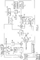
- the function of range gain against range is illustrated in Figure 2.
- the range gain has a maximum value of 7 for target ranges below 6 metres and a minimum value of 1 for target ranges above 20 metres. Between 6 and 20 metres, the range gain decreases monotonically and continuously or substantially continuously, for instance in the case of a digital system.
- the output of the multiplier 6 is added to the speed error signal by the adder 7, that is, in this embodiment, the multiplier 28 has a gain of one.
- the relatively low range gain of 1 is applied to the distance error and the speed error therefore has more influence on cruise control. Even with the relatively low range gain, if the distance error persists for a substantial time, the integral action of the throttle actuator 16 corrects the distance error smoothly.
- any distance error represents a relatively large proportion of the desired range and a quick response is required in order to remove the distance error and, for instance, prevent the vehicle from approaching too closely the further vehicle ahead of it.
- the distance error has substantially more influence than the speed error in controlling the vehicle.
- a signal is supplied to the second input of the circuit 2 which causes the circuit to halve the range gain set in accordance with the function illustrated in Figure 2.
- the comparator 26 detects when the distance error is relatively great so that the vehicle under cruise control is relatively far behind the vehicle ahead of it.
- the comparator 27 determines when the speed error is such that the vehicle under cruise control is closing on the vehicle ahead of it.
- the range gain is halved so as to prevent overshoot.
- the output of the adder 7 represents an acceleration demand signal which itself could be used to control acceleration of a vehicle by being suitably processed and applied, for instance, to the throttle actuator 16 and the brake actuator 17.
- the acceleration demand is compared with the actual vehicle acceleration in the subtracter 8 to form an acceleration error.
- the acceleration demand from the adder 7 is limited by the limiter 10 to a maximum value of +15%g and a minimum value of - 30%g.
- the vehicle under cruise control may not be able to accelerate quickly enough to stay within range of the lead vehicle.
- the limiter 10 is arranged to be disabled in respect of the upper limit value of +15%g if the acceleration demand from the adder 7 is greater than +15%g as determined by the comparator 23 but the actual vehicle acceleration calculated by the differentiator 9 is less than +10%g as determined by the comparator 24. In these circumstances, which correspond to adverse conditions of the type described hereinbefore, the limiter 10 allows a larger acceleration demand to be used to control drive of the vehicle.
- the integrating action of the throttle actuator 16 is such that the throttle opens at a greater rate so as to improve acceleration until the vehicle acceleration exceeds +10%g as detected by the comparator 24, at which point the limiter 10 then reverts to normal operation and limits the maximum value of the acceleration demand to +15%g.
- the cruise control apparatus is fitted to a vehicle having an anti-lock brake system
- braking control provided by the cruise control apparatus will be overridden if the anti-lock braking system detects excessive wheel slip during braking.
- control of the engine throttle by the cruise control apparatus will be overridden if the traction control system detects excessive wheel spin.
- the gating arrangement comprising the switches 11 and 12 the comparator 15 and the comparator 19 via the gate 18 ensure that positive acceleration demands control the engine throttle whereas negative acceleration demands control the vehicle brake.
- the thresholds T1 and T2 may be made substantially equal to zero or may be made positive and negative, respectively, by predetermined amounts so as to provide a "dead band" between throttle control and brake control.
- comparators 15 and 19 may be provided with hysteresis in order to prevent hunting or instability when the acceleration demand is close to the threshold T1 or the threshold T2.
- the gating arrangement ensures that control of vehicle drive and control of vehicle braking cannot occur simultaneously.
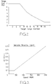
- the integration gain is a function of vehicle speed and may be stored as a look-up table in read only memory or calculated directly as a function of the vehicle speed. The function is illustrated in Figure 3. For relatively low speeds, for instance below about 35 km/h, the integration gain has a value of 0.1. For higher vehicle speeds, the integration gain increases linearly with speed so as to have a value of approximately 0.8 for a vehicle speed of 250 km/h. Thus, by varying the integration gain with speed, the cruise control apparatus provides a smooth response at slow speed and a fast response at higher speeds.
- the throttle actuator 16 integrates the control signal from the multiplier 13.
- the integrator which may be electronic or mechanical or any other suitable device, is pre-loaded with the current throttle position so that the throttle quickly assumes the desired position when cruise control is actuated.
- the acceleration error is supplied via the switch 12 to the brake actuator 17 for controlling the vehicle brake.
- the switch 12 is switched off and braking inhibited when the vehicle under cruise control is too close to the lead vehicle as determined by the comparator 21 and the speed of the vehicle under cruise control is less than that of the lead vehicle as determined by the comparator 20.
- the vehicle brake is not applied but instead the vehicle is allowed to coast so that it achieves the desired range.
- This brake inhibiting arrangement is preferably only enabled during an initial phase of cruise control operation when the vehicle under cruise control is initially being controlled to the desired range and to a vehicle speed matching that of the lead vehicle.
- the comparators 20 and 21 may be disabled so as to prevent inhibiting of the vehicle brake during subsequent cruise control operation.
- a cruise control apparatus which has stable operation and avoids hunting or oscillation about the desired range.
- driver intervention during cruise control operation is reduced and, in many circumstances, eliminated until the driver wishes to disable cruise control operation.
- the apparatus shown in Figure 1 thus provides automatic intelligent cruise control operation of a vehicle with minimal driver intervention when following a lead vehicle.
- the cruise control apparatus may be switchable by the driver from the operation described hereinbefore to conventional cruise control operation, wherein the vehicle is controlled to achieve a driver-selected target speed, when the vehicle is not following a lead vehicle.
Abstract
Description
- The present invention relates to a method of and an apparatus for cruise control.
- Known cruise controllers for vehicles allow a driver to set a target vehicle speed. The cruise controller then acts to maintain the vehicle speed at the target speed. Such a controller does not monitor the distance to or speed of vehicles ahead of the vehicle under cruise control. Thus, the driver has to intervene if the vehicle under cruise control approaches another vehicle too closely for the target speed, for instance so as to ensure that a safe braking distance remains between the vehicles. Even if the other vehicle is under cruise control and the driver of the other vehicle has set the same nominal target vehicle speed, variations and tolerances between the vehicles and the cruise controllers are such that the actual vehicle speeds when under cruise control will generally be slightly different. Again, if the following vehicle approaches the lead vehicle too closely, the driver has to intervene, for instance by switching off the cruise controller or by applying the vehicle brake, which normally disengages at least temporarily the cruise controller.
- According to a first aspect of the invention, there is provided a cruise control apparatus for a vehicle, comprising distance error determining means for determining a distance error as the difference between a desired distance between a target and the vehicle and the actual distance between the target and the vehicle, speed error determining means for determining a speed error as the difference between the speed of the target and the speed of the vehicle, and acceleration demand producing means for producing a vehicle acceleration demand as a function of the distance error and of the speed error.
- Preferably the acceleration demand is calculated as a sum of the product of the distance error and a first gain parameter and the product of the speed error and a second gain parameter. The second gain parameter may be a constant, for instance unity. Thus the acceleration demand is calculated as a weighted sum of the speed error and the distance error.
- The target is preferably a further vehicle ahead of the vehicle having the cruise control apparatus. The distance and speed errors may be determined by any suitable means, for instance in the form of an electromagnetic or ultra-sonic radar system for providing a direct measurement of the distance. The speed error may be obtained by differentiating the output of the radar system with respect to time. Alternatively, the speed error may be provided automatically by a suitable radar system, for instance of the döppler type.
- The apparatus may further comprise desired distance determining means for determining the desired distance as a function of the vehicle speed. For instance, the desired distance may be a linear function of the vehicle speed.
- The apparatus may further comprise gain setting means for setting at least one of the first and second gain parameters such that the quotient of the first gain parameter divided by the second gain parameter is a function of the distance and/or distance error. The gain setting means may set the quotient to a first value for a first distance error or a first actual distance and to a second value less than the first value for a second distance error or a second actual distance greater than the first distance error or the first actual distance. The first and second values may comprise maximum and minimum values, for
instance - The apparatus may further comprise acceleration error producing means for producing an acceleration error as the difference between the acceleration demand and the actual vehicle acceleration.
- The apparatus may further comprise gating means for supplying the acceleration error to a vehicle drive system when the acceleration demand is greater than a first threshold which is greater than or equal to zero, and for supplying the acceleration error to a vehicle brake system when the acceleration demand is less than a second threshold which is less than or equal to zero. Inhibiting means may be provided for inhibiting the supply of the acceleration error to the vehicle brake system when the acceleration demand is less than the second threshold, the distance error is less than a second predetermined distance error which is less than zero, and the speed error is less than a second predetermined speed error which is less than zero.
- For a vehicle driven by an internal combustion engine having a throttle controlled in cruise mode by an integrating controller, the apparatus may comprise further gain setting means for multiplying the acceleration error by a third gain parameter which is a function of the vehicle speed. The third gain parameter may have a constant value below a predetermined vehicle speed and a value which increases monotonically, for instance linearly, with vehicle speed above the predetermined vehicle speed. The apparatus may further comprise limiting means for limiting the acceleration demand or error to less than a first positive demand threshold and greater than a negative demand threshold. The apparatus may further comprise disabling means for disabling the limiter when the acceleration demand is greater than the first positive demand threshold and the vehicle acceleration is less than a second positive demand threshold which is less than the first positive demand threshold. For instance, the first and second positive demand thresholds may be 15%g and 10%g, respectively, and the negative demand threshold may be -30%g, where g is acceleration due to gravity.
- According to a second aspect of the invention, there is provided a method of cruise control for a vehicle, comprising determining a distance error as the difference between a desired distance between a target and the vehicle and the actual distance between the target and the vehicle, determining a speed error as the difference between the speed of the target and the speed of the vehicle, and controlling the vehicle in accordance with a vehicle acceleration demand formed as a function of the distance error and the speed error.
- Preferably the vehicle acceleration demand is formed as the sum of the product of the distance error and a first gain parameter and the product of the speed error and a second gain parameter.
- It is thus possible to provide cruise control in which a vehicle is capable of matching its speed to a further vehicle ahead of it while maintaining a desired distance from the further vehicle. Thus, when in cruise control mode, driver intervention can be reduced or substantially eliminated irrespective of the speed of the further vehicle.
- The present invention will be further described, by way of example, with reference to the accompanying drawings, in which:
- Figure 1 is a schematic diagram of a cruise control apparatus constituting an embodiment of the present invention;
- Figure 2 is a graph of range gain versus distance to a target; and
- Figure 3 is a graph of throttle integrator gain as a function of vehicle speed.
- The cruise control apparatus shown in Figure 1 is provided in a vehicle driven by an internal combustion engine and comprises a
radar system 1 which is mounted at the front of the vehicle and faces forwards so as to detect a further vehicle ahead of the vehicle. Theradar system 1 provides a range output corresponding to the distance between the vehicle and the further vehicle and a relative speed output Vrel which corresponds to the difference in speeds of the vehicle and the further vehicle. - The range output of the
radar system 1 is supplied to the adding input of asubtracter 3. The subtracting input of thesubtracter 3 is connected to the output of a desiredrange setting circuit 4 whose input is connected to avehicle speed sensor 5 for determining the speed of the vehicle. Thesensor 5 may comprise any suitable sensor, such as an optical speed over ground sensor or a system for determining vehicle speed based on measurements of wheel speeds. - The output of the
subtracter 3 is supplied to a first input of amultiplier 6 whose second input is connected to the output of a rangegain setting circuit 2 having an input connected to the range output of theradar system 1. The output of themultiplier 6 is connected to a first input of anadder 7 whose second input is connected to theradar system 1 via amultiplier 28 so as to receive the relative speed signal. The multiplier is arranged to scale the relative speed signal prior to use by theadder 7. Themultiplier 28 may be omitted if a gain of unity is applied to the relative speed signal. The output of theadder 7 is connected to the input of alimiter 10 for limiting the maximum positive and negative values of the acceleration demand signal. For instance, the maximum positive acceleration may be limited so as to be less than or equal to 15%g and the maximum deceleration may be limited so as to be less than or equal to 30%g, where g is acceleration due to gravity. The limited acceleration demand signal from thelimiter 10 is supplied to the adding input of asubtracter 8 whose subtracting input is connected to the output of adifferentiator 9. The input of thedifferentiator 9 is connected to the vehicle speed sensor so that thedifferentiator 9 provides a signal corresponding to the vehicle acceleration. - The output of the
subtracter 8, which represents an acceleration error signal, is supplied to a gating arrangement comprisingelectronic switches switch 11 selectively connects the output of thesubtracter 8 to a first input of amultiplier 13 whose second input is connected to the output of an integrationgain setting circuit 14. The input of thecircuit 14 is connected to the output of thevehicle speed sensor 5. Theswitch 11 is controlled by acomparator 15 having a first input connected to the output of thelimiter 10 and a second input connected to receive a first threshold T1 which corresponds to an acceleration error which is normally greater than zero. The output of themultiplier 13 is connected to the input of athrottle actuator 16 of the internal combustion engine of the vehicle. The throttle actuator is of the type which controls the engine throttle in accordance with the integral with respect to time of the signal supplied thereto. - The
switch 12 selectively connects the output of thesubtracter 8 to abrake actuator 17 of the vehicle. Theswitch 12 has a control input connected to the output of an ANDgate 18 having three inputs. The first input is connected to the output of acomparator 19 having a first input connected to the output of thelimiter 10 and a second input connected to receive a threshold T2 corresponding to an acceleration which is less than zero. The second input of thegate 18 is connected to acomparator 20 having a first input connected to theradar system 1 so as to receive the relative speed signal and a second input connected to receive a threshold T3 corresponding to a relative speed or speed error which is less than zero. The third input of thegate 18 is connected to the output of acomparator 21 which has a first input connected to the output of thesubtracter 3 so as to receive a range error signal and a second input connected to receive a threshold T4 corresponding to a range or distance error which is less than zero. - The
limiter 10 has a disabling input for preventing the limiter from limiting the acceleration demand signal to the predetermined maximum limit value. The disabling input is connected to the output of an ANDgate 22 which has two inputs. The first input of thegate 22 is connected to the output of acomparator 23 having a first input connected to the output of theadder 7 and a second input for receiving a threshold T5 corresponding to an acceleration demand which is equal to the maximum or upper limit value of the limiter. The second input of thegate 22 is connected to the output of acomparator 24 having a first input connected to the output of thedifferentiator 9 and a second input for receiving a threshold T6 corresponding to an acceleration between zero and the upper limit value. In the case where the upper limit value of thelimiter 10 is 15%g, the threshold T6 may correspond to 10%g. - The range
gain setting circuit 2 has an input connected to the output of an ANDgate 25 having two inputs. The first input of thegate 25 is connected to the output of acomparator 26 having a first input connected to the output of thesubtracter 3 and a second input for receiving a threshold T7 corresponding to a predetermined distance error which is greater than zero. The second input of thegate 25 is connected to the output of acomparator 27 having a first input connected to receive the relative velocity signal from theradar system 1 and a second input for receiving a threshold T8 which corresponds to a predetermined speed error which is greater than zero. - When cruise control is selected, the cruise control apparatus shown in Figure 1 controls the engine throttle and vehicle brake system automatically unless and until cruise control is disabled, for instance by the driver switching off cruise control or operating the accelerator or brake controls of the vehicle. The
radar system 1 supplies range and relative speed signals corresponding to the distance between the vehicle and the closest other vehicle ahead of it and the difference between the speeds of the two vehicles. The range is supplied to thesubtracter 3. Thesubtracter 3 forms a range error signal by subtracting the actual range from a desired range generated by thecircuit 4. Thecircuit 4 sets the desired range as a function of the vehicle speed measured by thesensor 5. Thecircuit 4 may comprise a look-up table stored in a read only memory or a calculating circuit for calculating values of the function based on the vehicle speed. For instance, the desired range S may be determined in accordance with the following function:
where the desired range S is given in metres and V is the vehicle speed in kilometres per hour. - In the absence of the constant 7 metres, the vehicle would be arranged to follow the further vehicle with a time separation of 0.83 seconds. However, for increased flexibility, the desired
range setting circuit 4 may be controllable by the driver so as to select any time separation, and hence desired range, within predetermined limits, for instance of 0.8 and 2.5 seconds. The constant 7 metres ensures that, for relatively low speeds, the vehicle maintains a minimum spacing from the further vehicle ahead of it so that, for instance, if the further vehicle were to stop, the vehicle in cruise control would stop with a desired range sufficient to prevent a collision. - The range or distance error from the
subtracter 3 is multiplied in themultiplier 6 by a range gain which is set in thecircuit 2. Thecircuit 2 may comprise a look-up table stored in read only memory or means for calculating the range gain primarily as a function of the actual range or distance between the two vehicles. The function of range gain against range is illustrated in Figure 2. The range gain has a maximum value of 7 for target ranges below 6 metres and a minimum value of 1 for target ranges above 20 metres. Between 6 and 20 metres, the range gain decreases monotonically and continuously or substantially continuously, for instance in the case of a digital system. - The output of the
multiplier 6 is added to the speed error signal by theadder 7, that is, in this embodiment, themultiplier 28 has a gain of one. Thus, for target ranges of 20 metres and above, the relatively low range gain of 1 is applied to the distance error and the speed error therefore has more influence on cruise control. Even with the relatively low range gain, if the distance error persists for a substantial time, the integral action of thethrottle actuator 16 corrects the distance error smoothly. - For relatively small desired ranges, a quicker response to distance error is required and the gain is progressively increased for desired ranges below 20 metres until it reaches the maximum value of 7 at 6 metres and below. For such small desired ranges, any distance error represents a relatively large proportion of the desired range and a quick response is required in order to remove the distance error and, for instance, prevent the vehicle from approaching too closely the further vehicle ahead of it.
- Thus, for relatively small desired ranges, the distance error has substantially more influence than the speed error in controlling the vehicle.
- When the output of the
gate 25 is active, a signal is supplied to the second input of thecircuit 2 which causes the circuit to halve the range gain set in accordance with the function illustrated in Figure 2. Thecomparator 26 detects when the distance error is relatively great so that the vehicle under cruise control is relatively far behind the vehicle ahead of it. Thecomparator 27 determines when the speed error is such that the vehicle under cruise control is closing on the vehicle ahead of it. Thus, when the controlled vehicle is closing but is relatively far behind the lead vehicle, the range gain is halved so as to prevent overshoot. - The output of the
adder 7 represents an acceleration demand signal which itself could be used to control acceleration of a vehicle by being suitably processed and applied, for instance, to thethrottle actuator 16 and thebrake actuator 17. However, in order to provide closed loop control of acceleration, the acceleration demand is compared with the actual vehicle acceleration in thesubtracter 8 to form an acceleration error. The acceleration demand from theadder 7 is limited by thelimiter 10 to a maximum value of +15%g and a minimum value of - 30%g. These maximum values of acceleration and deceleration have been found to be advantageous for the comfort of passengers in the vehicle. However, a problem may occur when a lead vehicle accelerates quickly, or is moving up a relatively steep gradient (or a combination of such adverse situations). In such combinations, the vehicle under cruise control may not be able to accelerate quickly enough to stay within range of the lead vehicle. In order to avoid or reduce the likelihood of such a problem, thelimiter 10 is arranged to be disabled in respect of the upper limit value of +15%g if the acceleration demand from theadder 7 is greater than +15%g as determined by thecomparator 23 but the actual vehicle acceleration calculated by thedifferentiator 9 is less than +10%g as determined by thecomparator 24. In these circumstances, which correspond to adverse conditions of the type described hereinbefore, thelimiter 10 allows a larger acceleration demand to be used to control drive of the vehicle. The integrating action of thethrottle actuator 16 is such that the throttle opens at a greater rate so as to improve acceleration until the vehicle acceleration exceeds +10%g as detected by thecomparator 24, at which point thelimiter 10 then reverts to normal operation and limits the maximum value of the acceleration demand to +15%g. - Where the cruise control apparatus is fitted to a vehicle having an anti-lock brake system, then braking control provided by the cruise control apparatus will be overridden if the anti-lock braking system detects excessive wheel slip during braking. Similarly, if the vehicle is provided with automatic traction control, then control of the engine throttle by the cruise control apparatus will be overridden if the traction control system detects excessive wheel spin.
- The gating arrangement comprising the
switches comparator 15 and thecomparator 19 via thegate 18 ensure that positive acceleration demands control the engine throttle whereas negative acceleration demands control the vehicle brake. The thresholds T1 and T2 may be made substantially equal to zero or may be made positive and negative, respectively, by predetermined amounts so as to provide a "dead band" between throttle control and brake control. - Similarly, the
comparators - When the limited acceleration demand from the
limiter 10 exceeds the threshold T1, thecomparator 15 switches on theswitch 11 and the acceleration error is multiplied by the integration gain from thecircuit 14. The integration gain is a function of vehicle speed and may be stored as a look-up table in read only memory or calculated directly as a function of the vehicle speed. The function is illustrated in Figure 3. For relatively low speeds, for instance below about 35 km/h, the integration gain has a value of 0.1. For higher vehicle speeds, the integration gain increases linearly with speed so as to have a value of approximately 0.8 for a vehicle speed of 250 km/h. Thus, by varying the integration gain with speed, the cruise control apparatus provides a smooth response at slow speed and a fast response at higher speeds. - The
throttle actuator 16, as described hereinbefore, integrates the control signal from themultiplier 13. When not in cruise control, the integrator, which may be electronic or mechanical or any other suitable device, is pre-loaded with the current throttle position so that the throttle quickly assumes the desired position when cruise control is actuated. - When the acceleration demand is less than the threshold T2, the acceleration error is supplied via the
switch 12 to thebrake actuator 17 for controlling the vehicle brake. However, theswitch 12 is switched off and braking inhibited when the vehicle under cruise control is too close to the lead vehicle as determined by thecomparator 21 and the speed of the vehicle under cruise control is less than that of the lead vehicle as determined by thecomparator 20. In these conditions, the vehicle brake is not applied but instead the vehicle is allowed to coast so that it achieves the desired range. This brake inhibiting arrangement is preferably only enabled during an initial phase of cruise control operation when the vehicle under cruise control is initially being controlled to the desired range and to a vehicle speed matching that of the lead vehicle. Once this has been achieved, thecomparators
By effectively controlling the acceleration of a vehicle in accordance with errors in the range and relative speeds, it has been found possible to provide a cruise control apparatus which has stable operation and avoids hunting or oscillation about the desired range. By matching the speed of the vehicle under cruise control to that of the lead vehicle and maintaining a desired range from the lead vehicle, driver intervention during cruise control operation is reduced and, in many circumstances, eliminated until the driver wishes to disable cruise control operation. The apparatus shown in Figure 1 thus provides automatic intelligent cruise control operation of a vehicle with minimal driver intervention when following a lead vehicle. If desired, the cruise control apparatus may be switchable by the driver from the operation described hereinbefore to conventional cruise control operation, wherein the vehicle is controlled to achieve a driver-selected target speed, when the vehicle is not following a lead vehicle.
Claims (21)
- A cruise control apparatus for a vehicle, characterised by distance error determining means (1, 3, 4, 5) for determining a distance error as the difference between a desired distance between a target and the vehicle and the actual distance between the target and the vehicle, speed error determining means (1) for determining a speed error as the difference between the speed of the target and the speed of the vehicle, and acceleration demand producing means (2, 6, 7, 28) for producing a vehicle acceleration demand as a function of the distance error and the speed error.
- A cruise control apparatus as claimed in Claim 1, characterised in that the vehicle acceleration demand producing means (2, 6, 7, 28) is arranged to calculate the vehicle acceleration demand as the sum of the product of the distance error and a first gain parameter and the product of the speed error and a second gain parameter.
- A cruise control apparatus as claimed in Claim 1 or 2, characterised by further comprising desired distance determining means (4) for determining the desired distance as a function of vehicle speed.
- A cruise control apparatus as claimed in Claim 2 or Claim 3 when dependent on Claim 2, characterised by further comprising gain setting means (2, 28) for setting at least one of the first and second gain parameters such that the quotient of the first gain parameter divided by the second gain parameter is a function of at least one of the distance and the distance error.
- A cruise control apparatus as claimed in Claim 4, characterised in that the gain setting means (2) is arranged to set the quotient to a first value for a first distance error or a first actual distance and to a second value less than the first value for a second distance error or second actual distance greater than the first distance error or the first actual distance.
- A cruise control apparatus as claimed in Claim 5, characterised in that the gain setting means (2) is arranged to set the quotient as a monotonically decreasing function of the distance error between the first and second distance errors or of the actual distance between the first and second distances.
- A cruise control apparatus as claimed in any one of Claims 4 to 6, characterised in that the gain setting means (2, 28) is arranged to substantially halve the value of the quotient when the distance error is greater than a first predetermined distance error (T7) which is greater than zero and the speed error is greater than a first predetermined speed error which is greater than zero.
- A cruise control apparatus as claimed in any one of the preceding claims, characterised by further comprising gating means (11, 12) for supplying the acceleration demand to a vehicle drive system when the acceleration demand is greater than a first threshold which is greater than or equal to zero, and for supplying the acceleration demand to a vehicle brake system when the acceleration demand is less than a second threshold which is less than or equal to zero.
- A cruise control apparatus as claimed in Claim 8, characterised by further comprising inhibiting means (18-21) for inhibiting the supply of the acceleration demand to the vehicle brake system when the acceleration demand is greater than the second threshold (T2), the distance error is greater than a second predetermined distance error (T4) which is less than zero, and the speed error is greater than a second predetermined speed error (T3) which is less than zero.
- A cruise control apparatus as claimed in any one of Claims 1 to 7, characterised by further comprising acceleration error producing means (8, 9) for producing an acceleration error as the difference between the acceleration demand and the actual vehicle acceleration.
- A cruise control apparatus as claimed in Claim 10, characterised by further comprising gating means (11, 12) for supplying the acceleration error to a vehicle drive system (16) when the acceleration demand or error is greater than a first threshold (T1) which is greater than or equal to zero, and for supplying the acceleration error to a vehicle brake system (17) when the acceleration demand or error is less than a second threshold (T2) which is less than or equal to zero.
- A cruise control apparatus as claimed in Claim 11, characterised by further comprising inhibiting means (18-21) for inhibiting the supply of the acceleration error to the vehicle brake system (17) when the acceleration demand or error is greater than the second threshold (T2), the distance error is greater than a second predetermined distance error (T4) which is less than zero, and the speed error is greater than a second predetermined speed error (T3) which is less than zero.
- A cruise control apparatus as claimed in any one of Claims 1 to 9 for use in a vehicle driven by an internal combustion engine having a throttle controlled in cruise mode by an integrating controller (16), characterised by further comprising further gain setting means (13, 14) for multiplying the acceleration demand by a third gain parameter which is a function of vehicle speed.
- A cruise control apparatus as claimed in any one of Claims 10 to 12 for use in a vehicle driven by an internal combustion engine having a throttle controlled in a cruise mode by an integrating controller (16), characterised by further comprising further gain setting means (13, 14) for multiplying the acceleration error by a third gain parameter which is a function of the vehicle speed.
- A cruise control apparatus as claimed in Claim 13 or 14, characterised in that the third gain parameter has a constant value below a predetermined vehicle speed and a value which increases monotonically with vehicle speed above the predetermined vehicle speed.
- A cruise control apparatus as claimed in any one of Claims 1 to 9 or 13 or 15 when dependent on 13, characterised by further comprising limiting means (10) for limiting the acceleration demand to less than a first positive demand threshold and greater than a negative demand threshold.
- A cruise control apparatus as claimed in Claim 2 or any claim dependent on Claim 2, characterised in that the second gain parameter is a constant.
- A cruise control apparatus as claimed in Claim 17, characterised in that the second gain parameter has a value of one.
- A cruise control apparatus as claimed in any one of the preceding claims, characterised in that the distance to and relative speed of the target are measured using a radar system (1).
- A method of cruise control for a vehicle, comprising determining a distance error as the difference between a desired distance between a target and the vehicle and the actual distance between the target and the vehicle, determining a speed error as the difference between the speed of the target and the speed of the vehicle, and controlling the vehicle in accordance with a vehicle acceleration demand formed as a function of the distance error and the speed error.
- A method as claimed in Claim 20, characterised in that the vehicle acceleration demand is calculated as the sum of the product of the distance error and a first gain parameter and the product of the speed error and a second gain parameter.
Applications Claiming Priority (2)
| Application Number | Priority Date | Filing Date | Title |
|---|---|---|---|
| GB9303434 | 1993-02-20 | ||
| GB939303434A GB9303434D0 (en) | 1993-02-20 | 1993-02-20 | Method of and apparatus for cruise control |
Publications (2)
| Publication Number | Publication Date |
|---|---|
| EP0612641A1 true EP0612641A1 (en) | 1994-08-31 |
| EP0612641B1 EP0612641B1 (en) | 1997-05-21 |
Family
ID=10730760
Family Applications (1)
| Application Number | Title | Priority Date | Filing Date |
|---|---|---|---|
| EP94301082A Expired - Lifetime EP0612641B1 (en) | 1993-02-20 | 1994-02-15 | Method of and apparatus for cruise control |
Country Status (5)
| Country | Link |
|---|---|
| US (1) | US5495251A (en) |
| EP (1) | EP0612641B1 (en) |
| DE (1) | DE69403238T2 (en) |
| ES (1) | ES2104271T3 (en) |
| GB (1) | GB9303434D0 (en) |
Cited By (49)
| Publication number | Priority date | Publication date | Assignee | Title |
|---|---|---|---|---|
| DE19534562A1 (en) * | 1994-09-20 | 1996-03-28 | Nissan Motor | Automatic velocity control system for automobile |
| GB2295698A (en) * | 1994-12-01 | 1996-06-05 | Lucas Ind Plc | Cruise control system |
| FR2727656A1 (en) * | 1994-12-01 | 1996-06-07 | Lucas Ind Plc | SYSTEM FOR CONTROLLING CRUISE SPEED OF A VEHICLE |
| EP0716949A1 (en) | 1994-12-13 | 1996-06-19 | Lucas Industries Public Limited Company | Apparatus and method for cruise control |
| EP0720928A2 (en) | 1994-12-13 | 1996-07-10 | Lucas Industries Public Limited Company | Apparatus and method for cruise control |
| EP0729859A2 (en) * | 1995-03-01 | 1996-09-04 | Eaton VORAD Technologies, L.L.C. | System and method for integrating intelligent cruise control with an electronically controlled engine |
| FR2732651A1 (en) * | 1995-04-07 | 1996-10-11 | Renault | Regulation of longitudinal acceleration of motor vehicle |
| FR2741957A1 (en) * | 1995-12-05 | 1997-06-06 | Siemens Automotive Sa | METHOD FOR MEASURING THE SPEED OF A VEHICLE IN RELATION TO THE GROUND, USING A RADAR USING THE REFLECTION OF ELECTROMAGNETIC WAVES ON THE PAVEMENT |
| US5659304A (en) * | 1995-03-01 | 1997-08-19 | Eaton Corporation | System and method for collision warning based on dynamic deceleration capability using predicted road load |
| EP0798150A2 (en) * | 1996-03-26 | 1997-10-01 | Jaguar Cars Limited | Cruise control system with vehicle following mode |
| EP0813987A2 (en) * | 1996-06-20 | 1997-12-29 | Volkswagen Aktiengesellschaft | Method for controlling distance between a vehicle and other objects |
| DE19621075C1 (en) * | 1996-05-24 | 1998-02-12 | Siemens Ag | Housing for a distance measuring device in a motor vehicle |
| WO1998029279A2 (en) * | 1996-12-30 | 1998-07-09 | Continental Teves Ag & Co. Ohg | Method and device for steering or controlling a vehicle |
| US5839534A (en) * | 1995-03-01 | 1998-11-24 | Eaton Vorad Technologies, Llc | System and method for intelligent cruise control using standard engine control modes |
| WO1999007571A1 (en) * | 1997-08-11 | 1999-02-18 | Ab Volvo | Process and system for controlling the speed of a vehicle |
| FR2770016A1 (en) * | 1997-10-17 | 1999-04-23 | Renault | Method of regulation of distance between two motor vehicles |
| EP0896896A3 (en) * | 1997-08-11 | 1999-10-06 | Fuji Jukogyo Kabushiki Kaisha | Cruise control system for motor vehicle |
| WO2000005091A1 (en) | 1998-07-24 | 2000-02-03 | Lucas Industries Plc | Apparatus for modifying the operation of a vehicle based on the vehicle's position |
| WO2000006411A2 (en) | 1998-07-29 | 2000-02-10 | Lucas Industries Limited | Vehicle cruise control with automatic set speed reduction |
| WO2000009357A1 (en) | 1998-08-12 | 2000-02-24 | Lucas Industries Plc | Method of and apparatus for controlling headway |
| EP0982172A3 (en) * | 1998-08-26 | 2000-06-21 | Nissan Motor Co., Ltd. | Automatic velocity and spacing control apparatus for automotive vehicle |
| EP1020315A1 (en) * | 1999-01-14 | 2000-07-19 | Nissan Motor Company, Limited | Apparatus and method for automatically controlling vehicular velocity and inter-vehicle distance |
| US6283240B1 (en) | 1998-09-02 | 2001-09-04 | Rover Group Limited | Vehicle |
| FR2807717A1 (en) * | 2000-04-17 | 2001-10-19 | Bosch Gmbh Robert | METHOD AND DEVICE FOR ADAPTIVE REGULATION OF THE DISTANCE AND / OR SPEED OF A MOTOR VEHICLE |
| EP1055542A3 (en) * | 1999-05-25 | 2001-11-14 | Nissan Motor Company, Limited | Preceding vehicle follow-up control system with gain adjustment |
| WO2001087662A1 (en) * | 2000-05-16 | 2001-11-22 | Nissan Motor Co., Ltd. | Vehicle speed control system |
| EP1238848A1 (en) * | 2001-03-08 | 2002-09-11 | Renault s.a.s. | Deceleration control method for vehicles |
| WO2002083447A1 (en) * | 2001-04-12 | 2002-10-24 | Robert Bosch Gmbh | Method for regulating the speed of a motor vehicle |
| US6622810B2 (en) * | 2001-11-05 | 2003-09-23 | General Motors Corporation | Adaptive cruise control system |
| EP1110831A3 (en) * | 1999-12-22 | 2004-01-02 | Visteon Global Technologies, Inc. | Method and system for controlling vehicle deceleration in an adaptive speed control system based on vehicle speed |
| WO2004026611A1 (en) * | 2002-09-07 | 2004-04-01 | Robert Bosch Gmbh | Method and device for regulating the speed of a vehicle |
| WO2004045888A1 (en) | 2002-11-21 | 2004-06-03 | Lucas Automotive Gmbh | System for influencing the speed of a motor vehicle |
| WO2004045891A1 (en) | 2002-11-21 | 2004-06-03 | Lucas Automotive Gmbh | System for influencing the speed of a motor vehicle |
| WO2004045893A1 (en) * | 2002-11-21 | 2004-06-03 | Lucas Automotive Gmbh | System for influencing the speed of a motor vehicle |
| WO2004045896A1 (en) | 2002-11-21 | 2004-06-03 | Lucas Automotive Gmbh | System for influencing the speed of a motor vehicle |
| EP1484212A1 (en) * | 2003-06-04 | 2004-12-08 | Nissan Motor Co., Ltd. | Risk potential calculation device and driving assist system |
| US7162361B2 (en) | 2002-11-21 | 2007-01-09 | Lucas Automotive Gmbh | System for influencing the speed of a motor vehicle |
| FR2888536A1 (en) * | 2005-07-18 | 2007-01-19 | Peugeot Citroen Automobiles Sa | Inter-vehicle time limiting method for motor vehicle, involves comparing instantaneous inter-vehicle time with reference inter-vehicle time value and limiting engine torque of vehicle when inter-vehicle time reaches reference time value |
| US7177750B2 (en) | 2002-11-21 | 2007-02-13 | Lucas Automotive Gmbh | System for influencing the speed of a motor vehicle |
| US7248962B2 (en) | 2002-11-21 | 2007-07-24 | Lucas Automotive Gmbh | System for influencing the speed of a motor vehicle |
| WO2007147998A1 (en) * | 2006-06-23 | 2007-12-27 | Renault S.A.S | Method for regulating the distance between two vehicles |
| US7386385B2 (en) | 2002-11-21 | 2008-06-10 | Lucas Automotive Gmbh | System for recognising the lane-change manoeuver of a motor vehicle |
| US7831368B2 (en) | 2002-11-21 | 2010-11-09 | Lucas Automotive Gmbh | System for influencing the speed of a motor vehicle |
| US7831367B2 (en) | 2002-11-21 | 2010-11-09 | Lucas Automotive Gmbh | System for influencing the speed of a motor vehicle |
| DE19544923B4 (en) * | 1994-12-01 | 2012-11-29 | Lucas Industries Public Ltd. Co. | Device for cruise control |
| DE10330855B4 (en) * | 2003-07-09 | 2014-03-13 | Lucas Automotive Gmbh | System for warning the driver of a motor vehicle of critical traffic situations |
| CN104865579A (en) * | 2014-02-21 | 2015-08-26 | 株式会社电装 | Vehicle-installed Obstacle Detection Apparatus Having Function For Judging Motion Condition Of Detected Object |
| WO2016162256A1 (en) | 2015-04-07 | 2016-10-13 | Lucas Automotive Gmbh | Control system and method for allowing another motor vehicle to pull in front from a neighboring lane during acc operation of one's own motor vehicle |
| DE102015004476A1 (en) | 2015-04-07 | 2016-10-13 | Lucas Automotive Gmbh | A control system and method for assisting safe shattering of automobiles after an overtaking operation |
Families Citing this family (24)
| Publication number | Priority date | Publication date | Assignee | Title |
|---|---|---|---|---|
| DE19529173C1 (en) * | 1995-08-08 | 1997-01-09 | Siemens Ag | Radar device with reduced radiated power |
| US5899289A (en) * | 1995-10-31 | 1999-05-04 | Honda Giken Kogyo Kabushiki Kaisha | Automatically driven motor vehicle |
| JP3143063B2 (en) * | 1996-06-07 | 2001-03-07 | 株式会社日立製作所 | Travel control device for moving objects |
| JP3468001B2 (en) * | 1996-12-16 | 2003-11-17 | 日産自動車株式会社 | Travel control device for vehicles |
| US6078859A (en) * | 1997-08-04 | 2000-06-20 | Ford Global Technologies, Inc. | System and method for torque based vehicle speed control |
| US6233515B1 (en) * | 1998-12-07 | 2001-05-15 | Jaguar Car, Limited | Adaptive vehicle cruise control system and methodology |
| DE19958520A1 (en) * | 1999-12-04 | 2001-06-07 | Bosch Gmbh Robert | Speed controller for a motor vehicle |
| US6278931B1 (en) * | 2000-04-04 | 2001-08-21 | Delphi Technologies, Inc. | Motor vehicle cruise control with selectively updated integral gain |
| JP3777970B2 (en) * | 2000-11-02 | 2006-05-24 | 日産自動車株式会社 | Preceding vehicle tracking control device |
| GB0300974D0 (en) * | 2003-01-16 | 2003-02-19 | Ford Global Tech Inc | Adaptive cruise control apparatus |
| DE10310720A1 (en) * | 2003-03-10 | 2004-09-23 | Robert Bosch Gmbh | Method and device for regulating the speed of a motor vehicle |
| US7457699B2 (en) * | 2004-01-21 | 2008-11-25 | Delphi Technologies, Inc. | Technique for detecting truck trailer for stop and go adaptive cruise control |
| JP4484895B2 (en) * | 2007-04-23 | 2010-06-16 | 三菱電機株式会社 | In-vehicle radar system |
| JP4938542B2 (en) * | 2007-04-27 | 2012-05-23 | トヨタ自動車株式会社 | Vehicle speed control device for vehicle |
| JP4997031B2 (en) * | 2007-09-06 | 2012-08-08 | トヨタ自動車株式会社 | Vehicle travel control device |
| US8766738B2 (en) * | 2008-11-18 | 2014-07-01 | Nxp, B.V. | Decomposer and amplifier |
| US9308926B2 (en) * | 2008-12-29 | 2016-04-12 | Universal City Studios Llc | Position control system |
| US8463521B2 (en) * | 2009-12-23 | 2013-06-11 | Honda Motor Co., Ltd. | Vehicle driver coaching system and method |
| US10570839B2 (en) * | 2012-11-29 | 2020-02-25 | Ford Global Technologies, Llc | System and method for improving vehicle performance |
| US8862360B1 (en) | 2013-05-10 | 2014-10-14 | Caterpillar Inc. | Cruise control system |
| CN104290658B (en) * | 2014-09-29 | 2018-03-06 | 长安大学 | A kind of warning device and method for preceding road detection of unsafe condition |
| JP6344344B2 (en) * | 2015-09-09 | 2018-06-20 | トヨタ自動車株式会社 | Vehicle travel control device |
| CN111942377B (en) * | 2019-05-17 | 2021-09-14 | 上汽通用汽车有限公司 | Vehicle longitudinal motion control method and vehicle longitudinal motion control system |
| CN111189650A (en) * | 2020-01-22 | 2020-05-22 | 长安大学 | Unmanned vehicle cooperative driving capability test system and test method |
Citations (4)
| Publication number | Priority date | Publication date | Assignee | Title |
|---|---|---|---|---|
| DE4100993A1 (en) * | 1990-01-17 | 1991-07-25 | Mitsubishi Electric Corp | FOLLOW-UP CONTROL DEVICE AND METHOD FOR A MOTOR VEHICLE |
| EP0443644A1 (en) * | 1990-02-20 | 1991-08-28 | General Motors Corporation | Adaptive cruise control system |
| US5044457A (en) * | 1989-12-15 | 1991-09-03 | Aikman Steven W | Motor vehicle cruise control system having mode dependent gain |
| EP0484995A2 (en) * | 1990-11-05 | 1992-05-13 | General Motors Corporation | Method of controlling the speed of a vehicle |
Family Cites Families (2)
| Publication number | Priority date | Publication date | Assignee | Title |
|---|---|---|---|---|
| JPS5843009A (en) * | 1981-09-07 | 1983-03-12 | Toyota Motor Corp | Automatic speed controller of automobile |
| JPS60121130A (en) * | 1983-12-06 | 1985-06-28 | Nissan Motor Co Ltd | Vehicle travel control device |
-
1993
- 1993-02-20 GB GB939303434A patent/GB9303434D0/en active Pending
-
1994
- 1994-02-15 ES ES94301082T patent/ES2104271T3/en not_active Expired - Lifetime
- 1994-02-15 EP EP94301082A patent/EP0612641B1/en not_active Expired - Lifetime
- 1994-02-15 DE DE69403238T patent/DE69403238T2/en not_active Expired - Fee Related
- 1994-02-16 US US08/197,761 patent/US5495251A/en not_active Expired - Fee Related
Patent Citations (4)
| Publication number | Priority date | Publication date | Assignee | Title |
|---|---|---|---|---|
| US5044457A (en) * | 1989-12-15 | 1991-09-03 | Aikman Steven W | Motor vehicle cruise control system having mode dependent gain |
| DE4100993A1 (en) * | 1990-01-17 | 1991-07-25 | Mitsubishi Electric Corp | FOLLOW-UP CONTROL DEVICE AND METHOD FOR A MOTOR VEHICLE |
| EP0443644A1 (en) * | 1990-02-20 | 1991-08-28 | General Motors Corporation | Adaptive cruise control system |
| EP0484995A2 (en) * | 1990-11-05 | 1992-05-13 | General Motors Corporation | Method of controlling the speed of a vehicle |
Non-Patent Citations (4)
| Title |
|---|
| ANONYMOUS: "Adaptive Cruise System Smoothness Aspects", RESEARCH DISCLOSURE, vol. 325, no. 60, 10 May 1991 (1991-05-10), HAVANT GB, pages 320, XP007116387 * |
| DATABASE WPI Week 9111, Derwent World Patents Index; AN 91-079084, ANONYMOUS: "Adaptive cruise control for automotive vehicle determines desired braking effort as function proportional to vehicle speed error, or inter-vehicle spacing" * |
| DATABASE WPI Week 9123, 10 May 1991 Derwent World Patents Index; AN 91-169460, ANONYMOUS: "Adaptive vehicle cruise system provides speed error reduction rate proportional to both inter-vehicle spacing error and speed error" * |
| RESEARCH DISCLOSURE, vol. 322, no. 101, 10 February 1991 (1991-02-10) * |
Cited By (83)
| Publication number | Priority date | Publication date | Assignee | Title |
|---|---|---|---|---|
| US5731977A (en) * | 1994-09-20 | 1998-03-24 | Nissan Motor Co., Ltd. | Automatic speed control system for automotive vehicles |
| DE19534562A1 (en) * | 1994-09-20 | 1996-03-28 | Nissan Motor | Automatic velocity control system for automobile |
| GB2295698A (en) * | 1994-12-01 | 1996-06-05 | Lucas Ind Plc | Cruise control system |
| FR2727656A1 (en) * | 1994-12-01 | 1996-06-07 | Lucas Ind Plc | SYSTEM FOR CONTROLLING CRUISE SPEED OF A VEHICLE |
| DE19544923B4 (en) * | 1994-12-01 | 2012-11-29 | Lucas Industries Public Ltd. Co. | Device for cruise control |
| DE19544925B4 (en) * | 1994-12-01 | 2012-02-23 | Lucas Industries Public Ltd. Co. | Device for cruise control |
| GB2295698B (en) * | 1994-12-01 | 1999-04-07 | Lucas Ind Plc | Apparatus and method for cruise control |
| EP0716949A1 (en) | 1994-12-13 | 1996-06-19 | Lucas Industries Public Limited Company | Apparatus and method for cruise control |
| EP0720928A2 (en) | 1994-12-13 | 1996-07-10 | Lucas Industries Public Limited Company | Apparatus and method for cruise control |
| EP0720928A3 (en) * | 1994-12-13 | 1997-03-12 | Lucas Ind Plc | Apparatus and method for cruise control |
| US5761629A (en) * | 1994-12-13 | 1998-06-02 | Lucas Industries Public Limited Company | Method and apparatus for cruise control |
| US5749426A (en) * | 1994-12-13 | 1998-05-12 | Lucas Industries Public Limited Company | Apparatus and method for cruise control |
| US5659304A (en) * | 1995-03-01 | 1997-08-19 | Eaton Corporation | System and method for collision warning based on dynamic deceleration capability using predicted road load |
| EP0729859A3 (en) * | 1995-03-01 | 1998-04-15 | Eaton VORAD Technologies, L.L.C. | System and method for integrating intelligent cruise control with an electronically controlled engine |
| US5839534A (en) * | 1995-03-01 | 1998-11-24 | Eaton Vorad Technologies, Llc | System and method for intelligent cruise control using standard engine control modes |
| US6076622A (en) * | 1995-03-01 | 2000-06-20 | Eaton Vorad Technologies, Llc | System and method for intelligent cruise control using standard engine control modes |
| EP0729859A2 (en) * | 1995-03-01 | 1996-09-04 | Eaton VORAD Technologies, L.L.C. | System and method for integrating intelligent cruise control with an electronically controlled engine |
| FR2732651A1 (en) * | 1995-04-07 | 1996-10-11 | Renault | Regulation of longitudinal acceleration of motor vehicle |
| WO1997021111A1 (en) * | 1995-12-05 | 1997-06-12 | Siemens Automotive S.A. | Method for measuring the ground speed of a vehicle by means of a radar using the reflection of electromagnetic waves on the driving surface |
| FR2741957A1 (en) * | 1995-12-05 | 1997-06-06 | Siemens Automotive Sa | METHOD FOR MEASURING THE SPEED OF A VEHICLE IN RELATION TO THE GROUND, USING A RADAR USING THE REFLECTION OF ELECTROMAGNETIC WAVES ON THE PAVEMENT |
| EP0798150B1 (en) * | 1996-03-26 | 2001-01-17 | Jaguar Cars Limited | Cruise control system with vehicle following mode |
| EP0798150A2 (en) * | 1996-03-26 | 1997-10-01 | Jaguar Cars Limited | Cruise control system with vehicle following mode |
| DE19621075C1 (en) * | 1996-05-24 | 1998-02-12 | Siemens Ag | Housing for a distance measuring device in a motor vehicle |
| US5969640A (en) * | 1996-06-20 | 1999-10-19 | Volkswagen Ag | Method for spacing control for a motor vehicle |
| EP0813987A3 (en) * | 1996-06-20 | 1999-02-24 | Volkswagen Aktiengesellschaft | Method for controlling distance between a vehicle and other objects |
| EP0813987A2 (en) * | 1996-06-20 | 1997-12-29 | Volkswagen Aktiengesellschaft | Method for controlling distance between a vehicle and other objects |
| WO1998029279A2 (en) * | 1996-12-30 | 1998-07-09 | Continental Teves Ag & Co. Ohg | Method and device for steering or controlling a vehicle |
| WO1998029279A3 (en) * | 1996-12-30 | 1999-02-18 | Itt Mfg Enterprises Inc | Method and device for steering or controlling a vehicle |
| EP1285808A1 (en) * | 1996-12-30 | 2003-02-26 | Continental Teves AG & Co. oHG | Method and means of controlling and regulating a vehicle |
| EP0896896A3 (en) * | 1997-08-11 | 1999-10-06 | Fuji Jukogyo Kabushiki Kaisha | Cruise control system for motor vehicle |
| WO1999007571A1 (en) * | 1997-08-11 | 1999-02-18 | Ab Volvo | Process and system for controlling the speed of a vehicle |
| US6347273B1 (en) | 1997-08-11 | 2002-02-12 | Volvo Car Corporation | Process and system for controlling the speed of a vehicle |
| FR2770016A1 (en) * | 1997-10-17 | 1999-04-23 | Renault | Method of regulation of distance between two motor vehicles |
| WO1999020481A1 (en) * | 1997-10-17 | 1999-04-29 | Renault | Method for adaptative cruise control between two moving vehicles |
| WO2000005091A1 (en) | 1998-07-24 | 2000-02-03 | Lucas Industries Plc | Apparatus for modifying the operation of a vehicle based on the vehicle's position |
| WO2000006411A2 (en) | 1998-07-29 | 2000-02-10 | Lucas Industries Limited | Vehicle cruise control with automatic set speed reduction |
| WO2000006411A3 (en) * | 1998-07-29 | 2001-10-25 | Lucas Industries Ltd | Vehicle cruise control with automatic set speed reduction |
| WO2000009357A1 (en) | 1998-08-12 | 2000-02-24 | Lucas Industries Plc | Method of and apparatus for controlling headway |
| US6330507B1 (en) | 1998-08-26 | 2001-12-11 | Nissan Motor Co., Ltd. | Automatic vehicular velocity control apparatus for automotive vehicle |
| EP0982172A3 (en) * | 1998-08-26 | 2000-06-21 | Nissan Motor Co., Ltd. | Automatic velocity and spacing control apparatus for automotive vehicle |
| US6473686B2 (en) | 1998-08-26 | 2002-10-29 | Nissan Motor Co., Ltd. | Automatic vehicular velocity control apparatus for automotive vehicle |
| US6283240B1 (en) | 1998-09-02 | 2001-09-04 | Rover Group Limited | Vehicle |
| US6351702B1 (en) | 1999-01-14 | 2002-02-26 | Nissan Motor Co., Ltd. | Apparatus and method for automatically controlling vehicular velocity of vehicle |
| EP1020315A1 (en) * | 1999-01-14 | 2000-07-19 | Nissan Motor Company, Limited | Apparatus and method for automatically controlling vehicular velocity and inter-vehicle distance |
| EP1055542A3 (en) * | 1999-05-25 | 2001-11-14 | Nissan Motor Company, Limited | Preceding vehicle follow-up control system with gain adjustment |
| EP1110831A3 (en) * | 1999-12-22 | 2004-01-02 | Visteon Global Technologies, Inc. | Method and system for controlling vehicle deceleration in an adaptive speed control system based on vehicle speed |
| FR2807717A1 (en) * | 2000-04-17 | 2001-10-19 | Bosch Gmbh Robert | METHOD AND DEVICE FOR ADAPTIVE REGULATION OF THE DISTANCE AND / OR SPEED OF A MOTOR VEHICLE |
| US6732039B2 (en) | 2000-05-16 | 2004-05-04 | Nissan Motor Co., Ltd. | Vehicle speed control system |
| WO2001087662A1 (en) * | 2000-05-16 | 2001-11-22 | Nissan Motor Co., Ltd. | Vehicle speed control system |
| FR2821803A1 (en) * | 2001-03-08 | 2002-09-13 | Renault | ASSISTED DECELERATION PROCESS OF A MOTOR VEHICLE |
| EP1238848A1 (en) * | 2001-03-08 | 2002-09-11 | Renault s.a.s. | Deceleration control method for vehicles |
| WO2002083447A1 (en) * | 2001-04-12 | 2002-10-24 | Robert Bosch Gmbh | Method for regulating the speed of a motor vehicle |
| US6932441B2 (en) | 2001-04-12 | 2005-08-23 | Robert Bosch Gmbh | Method for regulating the speed of a motor vehicle |
| US6622810B2 (en) * | 2001-11-05 | 2003-09-23 | General Motors Corporation | Adaptive cruise control system |
| WO2004026611A1 (en) * | 2002-09-07 | 2004-04-01 | Robert Bosch Gmbh | Method and device for regulating the speed of a vehicle |
| DE10254402B4 (en) * | 2002-11-21 | 2011-02-17 | Lucas Automotive Gmbh | System for influencing the speed of a motor vehicle |
| US7774123B2 (en) | 2002-11-21 | 2010-08-10 | Lucas Automotive Gmbh | System for influencing the speed of a motor vehicle |
| WO2004045896A1 (en) | 2002-11-21 | 2004-06-03 | Lucas Automotive Gmbh | System for influencing the speed of a motor vehicle |
| US7162361B2 (en) | 2002-11-21 | 2007-01-09 | Lucas Automotive Gmbh | System for influencing the speed of a motor vehicle |
| WO2004045888A1 (en) | 2002-11-21 | 2004-06-03 | Lucas Automotive Gmbh | System for influencing the speed of a motor vehicle |
| WO2004045891A1 (en) | 2002-11-21 | 2004-06-03 | Lucas Automotive Gmbh | System for influencing the speed of a motor vehicle |
| WO2004045893A1 (en) * | 2002-11-21 | 2004-06-03 | Lucas Automotive Gmbh | System for influencing the speed of a motor vehicle |
| US7177750B2 (en) | 2002-11-21 | 2007-02-13 | Lucas Automotive Gmbh | System for influencing the speed of a motor vehicle |
| US7212907B2 (en) | 2002-11-21 | 2007-05-01 | Lucas Automotive Gmbh | System for influencing the speed of a motor vehicle |
| US7248962B2 (en) | 2002-11-21 | 2007-07-24 | Lucas Automotive Gmbh | System for influencing the speed of a motor vehicle |
| US7840330B2 (en) | 2002-11-21 | 2010-11-23 | Lucas Automotive Gmbh | System for influencing the speed of a motor vehicle |
| US7831367B2 (en) | 2002-11-21 | 2010-11-09 | Lucas Automotive Gmbh | System for influencing the speed of a motor vehicle |
| US7386385B2 (en) | 2002-11-21 | 2008-06-10 | Lucas Automotive Gmbh | System for recognising the lane-change manoeuver of a motor vehicle |
| US7831368B2 (en) | 2002-11-21 | 2010-11-09 | Lucas Automotive Gmbh | System for influencing the speed of a motor vehicle |
| EP1484212A1 (en) * | 2003-06-04 | 2004-12-08 | Nissan Motor Co., Ltd. | Risk potential calculation device and driving assist system |
| US7167798B2 (en) | 2003-06-04 | 2007-01-23 | Nissan Motor Co., Ltd. | Risk potential calculation device and driving assist system |
| DE10330855B4 (en) * | 2003-07-09 | 2014-03-13 | Lucas Automotive Gmbh | System for warning the driver of a motor vehicle of critical traffic situations |
| EP1745975A1 (en) * | 2005-07-18 | 2007-01-24 | Peugeot Citroën Automobiles S.A. | Method and Device for limiting time gap between vehicles |
| FR2888536A1 (en) * | 2005-07-18 | 2007-01-19 | Peugeot Citroen Automobiles Sa | Inter-vehicle time limiting method for motor vehicle, involves comparing instantaneous inter-vehicle time with reference inter-vehicle time value and limiting engine torque of vehicle when inter-vehicle time reaches reference time value |
| WO2007147998A1 (en) * | 2006-06-23 | 2007-12-27 | Renault S.A.S | Method for regulating the distance between two vehicles |
| FR2902737A1 (en) * | 2006-06-23 | 2007-12-28 | Renault Sas | METHOD FOR REGULATING THE DISTANCE BETWEEN TWO VEHICLES |
| KR101374753B1 (en) * | 2006-06-23 | 2014-03-17 | 르노 에스.아.에스. | Method for regulating the distance between two vehicles |
| CN104865579A (en) * | 2014-02-21 | 2015-08-26 | 株式会社电装 | Vehicle-installed Obstacle Detection Apparatus Having Function For Judging Motion Condition Of Detected Object |
| WO2016162256A1 (en) | 2015-04-07 | 2016-10-13 | Lucas Automotive Gmbh | Control system and method for allowing another motor vehicle to pull in front from a neighboring lane during acc operation of one's own motor vehicle |
| DE102015004476A1 (en) | 2015-04-07 | 2016-10-13 | Lucas Automotive Gmbh | A control system and method for assisting safe shattering of automobiles after an overtaking operation |
| WO2016162282A1 (en) | 2015-04-07 | 2016-10-13 | Lucas Automotive Gmbh | Control system and method for assisting motor vehicles in safely pulling in after overtaking |
| DE102015004478A1 (en) | 2015-04-07 | 2016-10-13 | Lucas Automotive Gmbh | A control system and method for enabling a shunting of another motor vehicle from a neighboring lane in the ACC operation of the own motor vehicle |
| US10235887B2 (en) | 2015-04-07 | 2019-03-19 | Lucas Automotive Gmbh | Control system and method for assisting motor vehicles in safely pulling in after overtaking |
Also Published As
| Publication number | Publication date |
|---|---|
| DE69403238D1 (en) | 1997-06-26 |
| EP0612641B1 (en) | 1997-05-21 |
| US5495251A (en) | 1996-02-27 |
| GB9303434D0 (en) | 1993-04-07 |
| ES2104271T3 (en) | 1997-10-01 |
| DE69403238T2 (en) | 1997-10-02 |
Similar Documents
| Publication | Publication Date | Title |
|---|---|---|
| EP0612641B1 (en) | Method of and apparatus for cruise control | |
| US5749426A (en) | Apparatus and method for cruise control | |
| US5771481A (en) | Apparatus and method for cruise control | |
| EP0716949B1 (en) | Apparatus and method for cruise control | |
| EP0046019B1 (en) | Automatic speed control systems | |
| US6470257B1 (en) | Adaptive cruise control system for automotive vehicles | |
| US5781103A (en) | Apparatus and method for cruise control | |
| US6618000B2 (en) | Method and device for controlling the distance from a vehicle to a preceding vehicle | |
| EP1486370A2 (en) | Preceding vehicle follow-up control system | |
| EP1053903B1 (en) | Vehicular velocity controlling apparatus and method to follow up a preceding vehicle. | |
| JP3675240B2 (en) | Vehicle tracking control device | |
| JP4028618B2 (en) | Method and apparatus for controlling the speed of a vehicle | |
| US20020138190A1 (en) | Method and device for setting the vehicle longitudinal velocity to a deired speed | |
| US6778897B2 (en) | Adaptive cruise control system and strategy | |
| US5749063A (en) | Automatic vehicle speed controlling apparatus | |
| US20050038591A1 (en) | Device for the longitudinally guiding a motor vehicle | |
| US6772059B2 (en) | Method for adaptive distance and/or driving speed adjustment in a motor vehicle | |
| EP1063626B1 (en) | Vehicle spacing control system | |
| EP1144217B1 (en) | Vehicle cruise controller with set speed reduction to maintain a predetermined distance behind a target vehicle, a vehicle including such a controller, a method of controlling a vehicle respectively and a computer program product implementing the method | |
| EP0519477B1 (en) | Constant speed maintaining apparatus for vehicle | |
| EP0227198A2 (en) | A constant speed cruise control system of duty ratio control type and a leading angle control method thereof | |
| GB2295698A (en) | Cruise control system | |
| JPH11278097A (en) | Running control device for vehicle | |
| JP2000313245A (en) | Travel control device for vehicle | |
| CN117460652A (en) | Method for controlling the braking torque of a vehicle during at least partially automatic driving on an uphill and/or downhill, computing device for a vehicle, and auxiliary system |
Legal Events
| Date | Code | Title | Description |
|---|---|---|---|
| PUAI | Public reference made under article 153(3) epc to a published international application that has entered the european phase |
Free format text: ORIGINAL CODE: 0009012 |
|
| AK | Designated contracting states |
Kind code of ref document: A1 Designated state(s): DE ES FR GB IT |
|
| 17P | Request for examination filed |
Effective date: 19950210 |
|
| 17Q | First examination report despatched |
Effective date: 19960109 |
|
| GRAG | Despatch of communication of intention to grant |
Free format text: ORIGINAL CODE: EPIDOS AGRA |
|
| GRAH | Despatch of communication of intention to grant a patent |
Free format text: ORIGINAL CODE: EPIDOS IGRA |
|
| GRAH | Despatch of communication of intention to grant a patent |
Free format text: ORIGINAL CODE: EPIDOS IGRA |
|
| GRAH | Despatch of communication of intention to grant a patent |
Free format text: ORIGINAL CODE: EPIDOS IGRA |
|
| GRAA | (expected) grant |
Free format text: ORIGINAL CODE: 0009210 |
|
| AK | Designated contracting states |
Kind code of ref document: B1 Designated state(s): DE ES FR GB IT |
|
| REF | Corresponds to: |
Ref document number: 69403238 Country of ref document: DE Date of ref document: 19970626 |
|
| ET | Fr: translation filed | ||
| RAP2 | Party data changed (patent owner data changed or rights of a patent transferred) |
Owner name: LUCAS INDUSTRIES PUBLIC LIMITED COMPANY |
|
| REG | Reference to a national code |
Ref country code: ES Ref legal event code: FG2A Ref document number: 2104271 Country of ref document: ES Kind code of ref document: T3 |
|
| PLBE | No opposition filed within time limit |
Free format text: ORIGINAL CODE: 0009261 |
|
| STAA | Information on the status of an ep patent application or granted ep patent |
Free format text: STATUS: NO OPPOSITION FILED WITHIN TIME LIMIT |
|
| 26N | No opposition filed | ||
| PGFP | Annual fee paid to national office [announced via postgrant information from national office to epo] |
Ref country code: DE Payment date: 19991231 Year of fee payment: 7 |
|
| PGFP | Annual fee paid to national office [announced via postgrant information from national office to epo] |
Ref country code: GB Payment date: 20000209 Year of fee payment: 7 |
|
| PGFP | Annual fee paid to national office [announced via postgrant information from national office to epo] |
Ref country code: FR Payment date: 20000210 Year of fee payment: 7 |
|
| PGFP | Annual fee paid to national office [announced via postgrant information from national office to epo] |
Ref country code: ES Payment date: 20000222 Year of fee payment: 7 |
|
| PG25 | Lapsed in a contracting state [announced via postgrant information from national office to epo] |
Ref country code: GB Free format text: LAPSE BECAUSE OF NON-PAYMENT OF DUE FEES Effective date: 20010215 |
|
| PG25 | Lapsed in a contracting state [announced via postgrant information from national office to epo] |
Ref country code: ES Free format text: LAPSE BECAUSE OF NON-PAYMENT OF DUE FEES Effective date: 20010216 |
|
| GBPC | Gb: european patent ceased through non-payment of renewal fee |
Effective date: 20010215 |
|
| PG25 | Lapsed in a contracting state [announced via postgrant information from national office to epo] |
Ref country code: FR Free format text: LAPSE BECAUSE OF NON-PAYMENT OF DUE FEES Effective date: 20011031 |
|
| REG | Reference to a national code |
Ref country code: FR Ref legal event code: ST |
|
| PG25 | Lapsed in a contracting state [announced via postgrant information from national office to epo] |
Ref country code: DE Free format text: LAPSE BECAUSE OF NON-PAYMENT OF DUE FEES Effective date: 20011201 |
|
| REG | Reference to a national code |
Ref country code: ES Ref legal event code: FD2A Effective date: 20030303 |
|
| PG25 | Lapsed in a contracting state [announced via postgrant information from national office to epo] |
Ref country code: IT Free format text: LAPSE BECAUSE OF NON-PAYMENT OF DUE FEES;WARNING: LAPSES OF ITALIAN PATENTS WITH EFFECTIVE DATE BEFORE 2007 MAY HAVE OCCURRED AT ANY TIME BEFORE 2007. THE CORRECT EFFECTIVE DATE MAY BE DIFFERENT FROM THE ONE RECORDED. Effective date: 20050215 |