EP0616445A1 - Duplex multicarrier digital radio communication system, mobile station and base station for it - Google Patents
Duplex multicarrier digital radio communication system, mobile station and base station for it Download PDFInfo
- Publication number
- EP0616445A1 EP0616445A1 EP94460008A EP94460008A EP0616445A1 EP 0616445 A1 EP0616445 A1 EP 0616445A1 EP 94460008 A EP94460008 A EP 94460008A EP 94460008 A EP94460008 A EP 94460008A EP 0616445 A1 EP0616445 A1 EP 0616445A1
- Authority
- EP
- European Patent Office
- Prior art keywords
- base station
- data
- signal
- terminals
- transmission
- Prior art date
- Legal status (The legal status is an assumption and is not a legal conclusion. Google has not performed a legal analysis and makes no representation as to the accuracy of the status listed.)
- Granted
Links
Images


Classifications
-
- H—ELECTRICITY
- H04—ELECTRIC COMMUNICATION TECHNIQUE
- H04B—TRANSMISSION
- H04B7/00—Radio transmission systems, i.e. using radiation field
- H04B7/24—Radio transmission systems, i.e. using radiation field for communication between two or more posts
- H04B7/26—Radio transmission systems, i.e. using radiation field for communication between two or more posts at least one of which is mobile
- H04B7/2621—Radio transmission systems, i.e. using radiation field for communication between two or more posts at least one of which is mobile using frequency division multiple access [FDMA]
-
- H—ELECTRICITY
- H04—ELECTRIC COMMUNICATION TECHNIQUE
- H04L—TRANSMISSION OF DIGITAL INFORMATION, e.g. TELEGRAPHIC COMMUNICATION
- H04L27/00—Modulated-carrier systems
- H04L27/26—Systems using multi-frequency codes
- H04L27/2601—Multicarrier modulation systems
- H04L27/2602—Signal structure
Definitions
- the field of the invention is that of digital radiocommunication between geographically distinct transmitting and receiving stations. More specifically, the invention relates to a radiocommunication system in which a base station can manage data exchanges over the air with several remote stations, and in particular mobile stations.
- the GSM system is based on a cellular approach: the geographic territory to be covered in small portions, or cells, each served by one or more base stations. This division into cells makes it possible to optimize the use of the radio spectrum, several cells being able to use the same portion of spectrum.
- Each base station can communicate over the air with a plurality of mobiles circulating in its cell. Furthermore, the base stations are linked to a switching center which provides connections between a mobile and a remote terminal (which is for example a subscriber to the switched network or another mobile).
- the communications managed by a base station are distributed over frequency channels (traffic channels). Each traffic channel is then shared in time multiplex by several mobile stations.
- a frequency hopping management algorithm between the various frequency channels makes it possible to improve the robustness of the system with respect to the phenomenon of fading ("fading", in English).
- This phenomenon of fading is indeed a crucial problem, especially in urban areas. More precisely, we know that under conditions of multi-propagation (a station receiving simultaneously several fields coming from the same transmitter) there can occur selective fading (Rayleigh process).
- the frequency hopping technique makes it possible to limit the effects of these fades, by regularly changing the transmission frequency.
- this technique has a major drawback, namely the complexity of the stations, and in particular of the mobile stations, these having to permanently modify the modulation and demodulation frequencies, with all the constraints of tuning that this can pose.
- the invention particularly aims to overcome these drawbacks of the state of the art.
- an objective of the present invention is to provide a digital radiocommunication system exhibiting good robustness with respect to poor transmission conditions.
- the invention aims to provide such a system capable of operating in the presence of multi-jets, interference, fading, ...
- Another object of the invention is to provide such a system, in which the speed / bandwidth ratio is optimized.
- the invention also aims to provide such a radiocommunication system, in which the network layout engineering is simplified, in particular as regards the location of the antennas of the base stations.
- a particular objective of the invention is also to provide such a system in which the geographic coverage of a base station can be easily modified over time, for example as a function of the evolution of its environment.
- the invention is based on the use of a COFDM modulation (Coded Orthogonal Frequency Division Multiplex (Multiplexing of Orthogonal Coded Frequencies)) in both directions of transmission, from a mobile station to a base station (uplink) and from a base station to a mobile station (downlink).
- COFDM modulation Coded Orthogonal Frequency Division Multiplex (Multiplexing of Orthogonal Coded Frequencies)
- the COFDM technique is already known in the field of digital broadcasting.
- it has the advantage, in addition to a very good robustness with respect to various disturbances, and in particular multi-routes, to allow the coverage of a large geographic territory by using a plurality of transmitters operating at a single modulation frequency. (single frequency network).
- the invention shows that, however, the COFDM is entirely usable in a radiocommunication system.
- said signal received by said base station is organized in successive frames each comprising a predetermined number of first data symbols, each frame being divided into time intervals each comprising at least one data symbol, and it is assigned to each of said mobiles at least one time interval, said mobile transmitting data only during the time intervals assigned to it.
- TDMA time division multiple access
- said signal from each of said base stations comprises synchronization data
- each of said mobiles comprises means for controlling the instant of transmission of said first symbols, as a function of said synchronization data.
- a guard interval is provided between each of said first data symbols, so as to absorb the synchronization differences between two mobile stations.
- Such a guard interval has already been proposed to avoid phenomena of intersymbol interference. According to the invention, it responds to another problem, namely the synchronization differences which may appear between two mobile stations (seen from the base station), for example because one of the mobile stations is close to an antenna, and the other distant (different transmission times).
- said second channel coding means perform a time and frequency interleaving of said data elements of said second source signal
- said first channel coding means perform a frequency only interleaving of said data elements of said first source signal
- the coding used is not the same in the two directions of transmission (unlike known radiocommunication systems).
- this coding is adapted to the particularities of each direction of transmission.
- due to the time distribution in the uplink direction there is no time interleaving. It is therefore not necessary, to carry out the decoding, to combine the data contained in several successive time intervals.
- each of said time intervals comprises a series of at least two first consecutive data symbols, and the first symbol of said series is a demodulation reference symbol, making it possible to perform in a base station a differential demodulation of the following symbols of said series.
- each mobile station it is indeed necessary for each mobile station to provide its own demodulation reference, in the case of differential demodulation. It is also possible to implement, in at least one of the directions of transmission, a coherent demodulation.
- said transmission and reception terminals are located so that the transmission times of a signal between each of said terminals and the associated base station are different.
- transmission times may depend on the location of the terminals (transmission time between the terminal and the base station) and / or on the use of different delays (possibly variable in time) for each terminal.
- the difference between two of said transmission times is greater than the inverse of the bandwidth of the signal transmitted by said mobile stations.
- the applied delay is greater than the time resolution capacity of the base station, which guarantees the dissociation of the energies coming from the different antennas.
- each base station is linked to a switching center (possibly via one or more intermediate levels, forming a tree network) which provides the necessary connections.
- the invention is not limited solely to radiotelephony to mobiles. Indeed, the good robustness and the high throughput offered by the COFDM technique make it possible to transmit data and / or images. Many computer, telematics, multimedia applications can therefore be envisaged.
- mobile station is used here to simplify the understanding of the invention, compared with known systems (GSM for example), but should not be limited strictly speaking to movable (“mobile”) terminals. They can also be fixed elements, or simply capable of being moved.
- the invention makes it possible to implement local networks, in which a base station controls (over the air) several telephone and / or computer terminals.
- the establishment of a such a network is particularly simple (absence of cabling), and this network is easily upgradeable (addition or deletion of a terminal).
- the invention therefore relates to a new radiocommunication system with mobiles, implementing multicarrier modulation in both directions of communication.
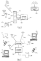
- Figure 1 shows an example of implementation of a cellular radio network according to the invention.
- the main characteristic of the invention is to associate with each base station (that is to say, in the case of a cellular network, with each cell) a plurality transmission / reception terminals.
- This new approach makes it possible, on the one hand, to take advantage of the advantages of single-frequency multi-carrier systems, and on the other hand to simplify the establishment and management of a network infrastructure.
- Each terminal of the same cell operates at the same transmit and receive frequencies.
- two neighboring cells use different frequencies.
- a first important characteristic of the invention appears directly from the view in FIG. 1 the shape and size of cells 11 1 to 11 4 can be any, and different from one cell to another.
- each cell comprises only a single antenna.
- the shape of the cells is therefore imposed: it is necessary that the perimeter thereof is substantially the same distance from a central point (the antenna).
- the cells should ideally be circular, and are in practice hexagonal (in the case of GSM).
- the shape can be arbitrary, and for example rectangular (cells 11 and 11 4 ). It is thus possible to adapt the shape of the cells as a function of needs and constraints, by appropriately placing the terminals 13 1 , 1 to 13 1.7 .
- Cell 11 1 has the form of the union (in the mathematical sense) of all of the covers 14 1.1 to 14 1.7 .
- cell 11 1 could be extended on its left by adding terminals 13 1 , 1 and 13 1.2 (case of the extension of a new district, the construction of a new road ... ).
- This flexibility is enabled by an essential characteristic of COFDM coding, which makes it possible to take advantage of multiple paths. This makes it possible, when viewed from mobiles, to create monofrequency broadcasting networks, that is to say networks comprising co-channel transmitters all transmitting on the same modulation frequency, each transmitter being seen as an echo.
- the mobile station (SM) 151.1 receives the contributions 16 1 and 16 2 and 16 3 from the terminals 13 1.1 and 13 1.2 and 13 1 , 3 respectively.
- the base station 12 1 receives signals transmitted by the mobile station 15 1,1 via the three terminals 13 1,1 and 13 1 , 2 and 13 1.3 .
- the base station 12 1 therefore forms in the uplink direction a receiver with spatial diversity (several distributed reception antennas). Again, we thus benefit from the echoes produced by the various contributions 17 1 and 17 2 and 17 3 .
- This characteristic also makes it possible to eliminate the gray areas in the cover of a cell. For example, if the zone 14 1 , 7 is not covered, a terminal 13 1 , 7 can be added, to remove the shadow zone. It should be noted that this addition can be made at any time, and for example when a new building has been constructed, masking zone 14 1.7 .
- each base station can manage a predefined number of communications.
- a high population density for example the center of a city
- the surface area of the cells may be increased (depending on the probability of the number of simultaneous calls).
- the system described above allows first of all to establish communications between two mobiles 15 1,1 and 15 1,2 circulating in the same cell 11 1 .
- This case also corresponds to the simplified embodiment where there is only one base station, and therefore only one cell (case of a network simply covering a city or a private site).
- the communication is then directly managed by the base station 12 1 . (It can also pass through switch 18, as in the following case).
- the network thus formed may include a tree structure on several levels, as well as GSM (each base station being connected to a base station controller, itself connected to a switching center).
- Communications can also be established, via the switch 18, with any other type of terminal 110 (telephone on the switched network, computer center, computer terminal, fax machine, etc.).
- FIG. 2 illustrates the transmission chain in the downward direction, that is to say from a base station 12, to a mobile station 15 1,1 .
- This chain of transmission is similar to that implemented in the case of COFDM broadcasting already known. However, it is recalled below, by way of example (other types of coding which can of course be implemented), the essential characteristics.
- COFDM Coded Orthogonal Frequency Division Multiplex
- the first principle is the distribution of the information to be transmitted over a large number of modulated carriers each at a low bit rate, in order to reduce the selectivity effect of the transmission channel (COFDM signal).
- the second principle of the COFDM system consists in correlating by a coding process consecutive information elements (channel coding) and in transmitting them to points distant from the time-frequency domain (technique of interleaving in time and in frequency). The distance between these points is chosen so as to ensure statistical independence between two successive elements of a source signal.
- Channel coding implements a convolutional code.
- the channel coding aspect does not relate directly to the present invention, the principle is briefly described in order to fully present an example of a broadcasting system which can implement the method of the invention. This is of course a simple, non-limiting example.
- the actual modulation process of this known system overcomes the problems associated with the frequency selectivity of the channel. It consists in ensuring the distribution of digital elements constituting the data signal in the frequency-time space and in simultaneously transmitting sets of digital elements on a plurality of parallel broadcasting channels by means of a frequency multiplex using frequencies orthogonal carriers. In particular, this type of modulation makes it possible to avoid two successive elements of the data train being transmitted at the same frequency.
- FIG. 2 is therefore a block diagram of a transmission chain (base station 219) and reception chain (mobile station 220) of a system implementing the COFDM technique.
- the source digital data 21 to be transmitted are subject to a convolutional coding 22.
- the general principle of such a code is to associate with each source value a coded value dependent on this value source and at least one of the values preceding it. Due to the link thus created between the coded values, it is then possible, on decoding, to reconstruct the sequence of the source values even when a received coded value is false, using a maximum likelihood decoding, such than a soft decision Viterbi decoding (that is to say a decoding delivering an estimate of the value received and a weighting representative of the confidence that can be given to this estimate).
- a maximum likelihood decoding such than a soft decision Viterbi decoding (that is to say a decoding delivering an estimate of the value received and a weighting representative of the confidence that can be given to this estimate).
- an external code of the Reed-Solomon or CSRS type (Cyclotomatically Shortened Reed Solomon (cyclotomatically shortened Reed Solomon code)) can be concatenated to the convolutional code.
- the source data can of course be of any type, be it audio signals, image signals or data signals. They can moreover correspond to several sources of distinct origins, emitted simultaneously.
- the COFDM system is based on the simultaneous use of a plurality of carrier frequencies transmitted simultaneously.
- the number N of carriers can be arbitrary. It is conventionally of the order of a few hundred (it could also be of the order of a few units).
- Each of these carriers is modulated at a low flow rate (compared to the flow rate required for a corresponding single-carrier system). This reduces the selectivity effect of the channel.
- the global signal emitted is therefore a broadband signal (occupying for example a band of a few megahertz).
- This wide band is an advantage, in the case of systems designed to take advantage of multipaths, such as COFDM. Indeed, due to the spreading of the response of the transmission channel, it is very improbable that a deep fading simultaneously affects the whole of the signal.
- the spectra of the different carriers overlap each other.
- the complete signal checks certain conditions of orthogonality, allowing the separation of the information associated with the different carriers, for example by using the technique of the Fourier transformation (as it is specified further on).
- the concept of orthogonality of the carrier frequencies implies that the spectra of the carriers can overlap, provided that, when one of the spectra exhibits its maximum power, that is to say at the frequency precise of the carrier corresponding to this spectrum, all the other spectra have zero power. The decoding is therefore not disturbed if we consider this precise frequency.
- the intersymbol interference introduced in particular by the multiple paths during the transmission can disturb this orthogonality.
- a guard interval is inserted between each symbol sent. The duration of this guard interval is chosen to be greater than the spread of the impulse response of the channel.
- the coding module 22 delivers coded data elements C k 23 belonging to a modulation alphabet.
- the choice of the alphabet specifies the type of modulation used. For example, for a modulation with 4 phase states (MDP4), the alphabet used is ⁇ 1 + i, 1 - i, -1 + i, -1 - i ⁇ .
- MDP4 modulation with 4 phase states
- Many other types of modulation can be used, such as MDP8,16QAM modulations or trellis coding modulations according to the Ungerboeck method.
- the coded data elements 23 are then subjected to an operation 24 of distribution in the frequency-time space, which consists in associating with each of the carrier frequencies data elements selected in the series of coded data 23 so as to break, by mixing, the correlation of the distortions suffered by the transmitted samples.
- time-frequency space is meant a set of points distributed along two perpendicular axes, the time axis and the frequency axis. According to the frequency axis, there are as many points as there are carrier frequencies. According to the time axis, a point corresponds to the duration of a symbol.
- this distribution ensures at least that two successive source data are not transmitted consecutively and / or on the same carrier frequency. More generally, the distance in time-frequency space between two successive coded data is at a minimum such that the statistical independence between these data is ensured.
- this distribution 24 in time-frequency space can correspond to an interleaving in time 24A consisting for example of a selective application of delays of different durations, followed by an interleaving in frequencies 24 8 , consisting of a selective allocation data elements delayed at different carriers.
- this interleaving in time is, in the case of telephone communications, different from that applied in currently developed broadcasting systems (DAB (Digital Audiobroadcasting)). More precisely, the delays applied are lower, and chosen so as not to disturb the communication (due to too long a delay between transmission and reception, as is for example the case in satellite communications).
- DAB Digital Audiobroadcasting
- Each carrier frequency is then modulated by the sequence of data elements C k which is intended for it.
- This modulation operation can be performed by applying an inverse fast Fourier transformation (FFT- 1 ) 26 to the series 25 of data elements.
- FFT- 1 inverse fast Fourier transformation
- These symbols 27 are then transmitted, in a conventional manner, using a transmission module 28, which in particular performs the digital / analog conversion of the symbols 27, then a transposition of the corresponding analog signal in the radio frequency domain.
- the signal is transmitted by all of the terminals associated with the base station 119.
- the transmission channel 29 (generally having multiple paths seen from the mobile 220) is received in a reception module 210 of this mobile, also conventional.
- each symbol received (not affected by intersymbol interference) can take the form: where H k represents the response of channel 29 at the frequency f k .
- This signal 211 is subjected to a transformation (FFT) 212, symmetrical with the inverse transformation 26.
- This transformation 212 delivers the following data elements 213:
- a deinterlacing module 216 performing the reverse operations of the module 24, so as to reconstitute the original order of the symbols, which are then directed into a decoding module 217, performing a decoding with maximum a posteriori likelihood, such as a soft decision Viterbi decoding.
- a decoding module 217 performing a decoding with maximum a posteriori likelihood, such as a soft decision Viterbi decoding.
- the multiplicative factor 1 H * j, k of the previous equation is directly representative of the confidence associated with the decision.
- N j , k is a complex Gaussian noise whose each component has a variance cr2j.k.
- the decoding module thus supplies, after a possible decoding of the concatenated code, if such a code has been implemented on transmission, the signal 218 corresponding to the source signal 21.
- FIG. 3 shows, by way of example, such a structure. More specifically, FIG. 3 illustrates a frame made up of M successive symbols.
- Each frame advantageously begins with two particular symbols S1 and S2, the role of which is explained below. It then comprises a certain number of useful symbols S3 to SM, each comprising N modulated orthogonal carriers 31.
- the symbol S1 is a null symbol (no signal is emitted during the duration of this symbol), making it possible on the one hand to carry out an analog synchronization, and on the other hand to carry out the spectral analysis of the possible jammers.
- the symbol S2 is a second synchronization symbol constituted by a multiplex of all the carrier frequencies modulated by fixed symbols (wobble symbol). Among other things, it allows synchronization to be reset more precisely by analyzing the channel's impulse response. The role and the embodiment of these symbols S1 and S2 are described in patent FR 88 15216, filed on 18.11.88.
- This symbol S2 can also be used as a phase reference for the demodulation of each carrier of the following symbols, when these are differentially modulated.
- each mobile station demodulates only the symbol sequence intended for it plus the symbol which immediately precedes this sequence, (principle of differential demodulation).
- the frame can also be divided into channels (Ci, Cj) grouping together for example a predetermined number of symbols, each channel containing for example the data intended for a given mobile station, or for a group of mobile stations.
- each symbol begins with a guard interval 22, which makes it possible to eliminate losses of orthogonality due to intersymbol interference.
- One of the essential advantages of the COFDM system is that the receivers are not disturbed by the received signal echoes. On the contrary, they take advantage of it.
- this system was designed in particular to allow the reception of digital signals in mobiles, even, and in particular, in particularly hostile transmission environments, such as urban environments.
- the COFDM system works in channels affected by multiple paths, due to the presence of natural obstacles (buildings, trees, vehicles, ).
- Such channels can be modeled by a Rayleigh distribution or a Rice-Nagakami distribution (if a path predominates).
- the receivers must include means for reconstructing the digital data transmitted, compensating for the problems due to the disturbances, and in particular to the echoes induced by the transmission channel.
- this result is achieved in particular thanks to interleaving in time and in frequency (frequency diversity), in the use of convolutional coding and in the presence of a guard interval between two symbols. consecutive data.
- This advantageous characteristic also makes it possible to use single-frequency broadcasting networks, that is to say networks comprising co-channel transmitters, all transmitting on the same modulation frequency, each transmitter being seen as an echo.
- multicarrier and “single frequency”, which do not apply to the same processing phase of the signal to be transmitted.
- the multicarrier signal corresponds to the useful baseband signal, which consists of a plurality of carriers (32; fig.3) each modulated by a data element.
- This baseband signal is then transposed into the radio frequency domain (28), by multiplication by a radiofrequency transmission frequency, with a view to its transmission.
- the system is said to be single frequency because each transmitter (each terminal) uses the same transmission frequency.
- the principle of monofrequency networks amounts to generating active echoes (interpreted as natural echoes), from a set of terminals distributed over the surface of a cell.
- Figure 4 shows the data transmission chain in the uplink direction. It has many points in common with the transmission chain in the downward direction of FIG. 2, but also certain specificities, due to the fact that several mobile stations 419, at 419 K can transmit to a single base station, the latter managing several communications simultaneously.
- the reception part, in the base station 420 is entirely similar to that carried out in the mobile station 220 in FIG. 2.
- the constitution and the operation of the elements 410 to 417 are therefore not repeated. Reference will be made to the corresponding elements 210 to 217.
- the operation is modified substantially, due to the use of a TDMA distribution.
- the coded data 43 are subjected to an interleaving in frequency 44 8 . However, these data are not temporally interleaved (unlike the downlink signal).
- each mobile station 419 operating only over a short period of time see Figure 5
- interleaving time as implemented in module 24A cannot be implemented.
- a particular time interleaving can however be envisaged, but limited to the number of symbols constituting each interval of a TDMA frame.
- the data 45 interleaved in frequency is then transformed using an FFT- 1 46 (identical to the FFT- 1 26), then transmitted using the transmission module 48.
- This module 48 performs the same functions than module 28, but only during the time interval which is allocated to the mobile station considered. It is therefore controlled by synchronization means 421.
- each mobile station 419 extracts synchronization data 422.
- the synchronization means 421 deliver to the transmission module 48 transmission authorizations 423, during the transmission moments allocated to the station.
- FIG. 5 shows an example of a symbol frame as received by the base station.
- the frame is divided into time intervals (or "slots" in English) Il (SH to SL), I j (SP to SQ), each interval being allocated to a mobile station.
- each interval begins with a synchronization symbol (thus, each mobile emits its own synchronization symbol).
- This synchronization symbol can also serve as a demodulation reference (as well as the S2 symbol already described), and as a gain reference (each mobile being received by the base station with variable powers).
- the allocation of the intervals is fixed: the interval I is systematically assigned to the mobile station i.
- this mobile station knows the location of this interval in the frame (for example in the form of a delay to be applied after reception of the synchronization symbols S1 and S2).
- the synchronization data 422 therefore correspond to the symbols S1 and S2.
- this allocation is dynamic: the base station allocates intervals as required (that is to say when a call is requested). In this case, at least some of the frames sent by the base station carrying an allocation descriptor.
- a channel of this frame (formed by one or more symbols) carries this descriptor, in a known format mobile stations. It is part of the synchronization data 422 taken into account by the synchronization means 421.
- this is the first channel of the frame.
- mobile stations for which no communication is in progress can operate intermittently. They go out of standby shortly before the start of the frame (synchronization symbol), then return to standby if the descriptor channel does not carry any information concerning them.
- this descriptor can begin with an indicator for a change in allocation. As long as this indicator retains a determined value, the mobile stations know that the allocation has not changed.
- the frame received (FIG. 5) by the base station comprises a symbol (or a channel) 53 in which all of the mobile stations can transmit communication requests.
- a particular mechanism manages possible collisions between two simultaneous requests (for example by a request for repetition in the allocation descriptor, or by repetition at regular or random time intervals, until the corresponding allocation appears in the descriptor).
- Each interval I or I j can include one or more symbols. However, if a differential demodulation (414) is implemented, each interval must include at least two symbols, the first (SQ, SP) being a demodulation reference symbol known to the base station.
- mobile stations may implement partial FFT, the data elements being adequately distributed over the corresponding carrier frequencies by the base station.
- Each symbol always begins with a guard interval 52, which makes it possible to absorb intersymbol interference and the differences in transmission time between two mobile stations.
- a base station 61 (notably comprising the elements contained in blocks 219, FIG. 2 and 420, FIG. 4) is connected to a coupler 62, by a bidirectional link 63. (This coupler can also be an integral part of the base station ).
- the coupler 62 is itself connected to several bidirectional radio terminals 64 1 to 64 N , by means of as many distribution links 65 1 to 65 N.
- bidirectional links 63 and 65 1 to 65 N can for example be coaxial or optical cables, so as to form a star network, or a tree (the tree structure can possibly have several levels).
- they may be radio links.
- FIG. 8 illustrates such a situation: the base station 81 is connected to the terminals 82 1 to 82 4 by a tree-coaxial network 83. In this architecture, the coupler is distributed between the connection points 84 1 to 84 3 .
- the coupler 62 plays the conventional role of combiner, in the upward direction, and of divider, in the downward direction.
- the signal received 63 M by the base station 61 corresponds to the combination of the signals received from the mobile 66 by each of the terminals 64 1 to 64 N.
- the signal transmitted 63 D by the base station 61 is transmitted by all of the terminals 64 1 to 64 N.
- Each terminal 64 1 to 64 N conventionally comprises a bidirectional amplifier, a transmission filter and a reception filter, and a bidirectional antenna.
- a separate delay T i 67 2 to 67 N is also associated with each terminal.
- the diversity of space can, under certain conditions, pose problems.
- the components of the two signals will combine into a single component.
- the resultant is very attenuated, even null.
- the two components are considered as echoes, which a COFDM receiver can handle.
- delays 67 2 to 76 N are therefore used , as has already been presented in French patent application FR 90 11192, in the significantly different (because unidirectional) context of broadcasting.
- delays are chosen so that the difference in any two of them is greater than the resolution in time T R of the receiver: for i, j 1 [1, N], i ⁇ j) or approximately: B being the bandwidth of the transmitted signal.
- the present invention is not limited to cellular telephone radiocommunications.
- many other applications can be envisaged, in particular because the COFDM technique offers the double advantage of a high throughput and great robustness.
- Figure 7 presents such a particular application to local networks.
- a local area network makes it possible to connect a plurality of computer terminals 71 1 , 712 to one another, so that these can exchange data and / or share peripherals (printer 72, for example).
- the system of the invention makes it possible to produce such a network, without wiring (if not, possibly, that between the coupler 73 and the transmission / reception terminals 74 1 to 74 N ).
- adding a new element 71 2 to the network is very simple: it suffices to provide it with transmission / reception means 75, and to declare its existence at the base station 76.
- the system can simultaneously manage other types of communications, such as telephone communications between telephone sets 77 i , 77 2 . Again, no wiring is necessary and these stations can be moved, even during communication.
- the base station 76 controls these different communications. It can also manage the transmission of specific data (paging system, broadcasting of animated or non-animated images, etc.). It can also control a data server 78.
Abstract
Description
Le domaine de l'invention est celui de la radiocommunication numérique entre des stations d'émission et de réception géographiquement distinctes. Plus précisément, l'invention concerne un système de radiocommunication dans lequel une station de base peut gérer des échanges de données par voie hertzienne avec plusieurs stations distantes, et en particulier des stations mobiles.The field of the invention is that of digital radiocommunication between geographically distinct transmitting and receiving stations. More specifically, the invention relates to a radiocommunication system in which a base station can manage data exchanges over the air with several remote stations, and in particular mobile stations.
On connaît déjà plusieurs systèmes de radiocommunication avec des mobiles mettant en oeuvre des structures de ce type. C'est notamment le cas des réseaux cellulaires tels que le système européen GSM ("Groupe Spécial Mobiles") actuellement disponible en Europe.Several radiocommunication systems with mobiles are already known employing structures of this type. This is particularly the case for cellular networks such as the European GSM system ("Groupe Spécial Mobiles") currently available in Europe.
Le système GSM repose en effet sur une approche cellulaire : le territoire géographique à couvrir en petites portions, ou cellules, desservies chacune par une ou plusieurs stations de base. Ce découpage en cellules permet d'optimiser l'utilisation du spectre radioélectrique, plusieurs cellules pouvant utiliser la même portion de spectre.The GSM system is based on a cellular approach: the geographic territory to be covered in small portions, or cells, each served by one or more base stations. This division into cells makes it possible to optimize the use of the radio spectrum, several cells being able to use the same portion of spectrum.
Chaque station de base peut communiquer par voie hertzienne avec une pluralité de mobiles circulant dans sa cellule. Par ailleurs, les stations de base sont reliées à un centre de commutation qui assure les connexions entre un mobile et un terminal distant (qui est par exemple un abonné du réseau commuté ou un autre mobile).Each base station can communicate over the air with a plurality of mobiles circulating in its cell. Furthermore, the base stations are linked to a switching center which provides connections between a mobile and a remote terminal (which is for example a subscriber to the switched network or another mobile).
Les communications gérées par une station de base sont réparties sur des canaux fréquentiels (canaux de trafic). Chaque canal de trafic est ensuite partagé en multiplex temporel par plusieurs stations mobiles. Un algorithme de gestion de sauts de fréquence entre les différents canaux fréquentiels permet d'améliorer la robustesse du système vis-à-vis du phénomène d'évanouissement ("fading", en anglo-saxon).The communications managed by a base station are distributed over frequency channels (traffic channels). Each traffic channel is then shared in time multiplex by several mobile stations. A frequency hopping management algorithm between the various frequency channels makes it possible to improve the robustness of the system with respect to the phenomenon of fading ("fading", in English).
Ce phénomène d'évanouissement est en effet un problème crucial, notamment en milieu urbain. Plus précisément, on sait que dans des conditions de multipropagation (une station recevant simultanément plusieurs champs en provenance d'un même émetteur) il peut se produire des évanouissements sélectifs (processus de Rayleigh). La technique du saut de fréquence permet de limiter les effets de ces évanouissements, en changeant régulièrement de fréquence d'émission. Toutefois, cette technique présente un inconvénient majeur, à savoir la complexité des stations, et notamment des stations mobi les, celles-ci devant en permanence modifier les fréquences de modulation et de démodulation, avec toutes les contraintes de réglage de l'accord que cela peut poser.This phenomenon of fading is indeed a crucial problem, especially in urban areas. More precisely, we know that under conditions of multi-propagation (a station receiving simultaneously several fields coming from the same transmitter) there can occur selective fading (Rayleigh process). The frequency hopping technique makes it possible to limit the effects of these fades, by regularly changing the transmission frequency. However, this technique has a major drawback, namely the complexity of the stations, and in particular of the mobile stations, these having to permanently modify the modulation and demodulation frequencies, with all the constraints of tuning that this can pose.
Par ailleurs, il apparaît que, dans certaines conditions de réception difficiles (multitrajets, masquage, parasites, brouillage, conditions atmosphériques, ...), la robustesse de ce système est insuffisante pour permettre un échange de données dans de bonnes conditions. Cela peut conduire à des interruptions momentanées (éventuellement acceptables dans le cas de signaux de parole, mais non dans le cas de signaux de données), et même à des coupures de la communication en cours.Furthermore, it appears that, under certain difficult reception conditions (multi-path, masking, parasites, interference, atmospheric conditions, etc.), the robustness of this system is insufficient to allow an exchange of data under good conditions. This can lead to momentary interruptions (possibly acceptable in the case of speech signals, but not in the case of data signals), and even to breaks in communication in progress.
Ces problèmes imposent des contraintes très importantes en ce qui concerne l'implantation de l'infrastructure des réseaux cellulaires, c'est-à-dire, en particulier, la détermination de l'emplacement géographique des antennes d'émission/réception des stations de base, des caractéristiques des émetteurs associés, de façon à répondre à un certain nombre de contraintes (couverture géographique, débit, ...). Notamment, l'antenne doit être placée sur un site élevé, pour limiter les effets de masquage, mais également être sensiblement centrée dans la cellule, de façon à couvrir suffisamment celle-ci tout en évitant que cette couverture déborde sur les cellules voisines ...These problems impose very important constraints with regard to the establishment of the infrastructure of the cellular networks, that is to say, in particular, the determination of the geographical location of the transmitting / receiving antennas of the radio stations. base, characteristics of the associated transmitters, so as to meet a certain number of constraints (geographic coverage, speed, ...). In particular, the antenna must be placed on a high site, to limit the masking effects, but also be substantially centered in the cell, so as to cover it sufficiently while avoiding that this coverage overflows on neighboring cells. .
Ces contraintes sont d'autant plus cruciales que les choix d'implantation sont définitifs, ou à tout le moins difficiles à modifier, du fait qu'ils influent sur les cellules voisines. Cela peut poser des problèmes lorsque l'environnement évolue (construction d'une route, d'un immeuble, ...).These constraints are all the more crucial as the location choices are final, or at the very least difficult to modify, because they influence neighboring cells. This can cause problems when the environment changes (construction of a road, a building, ...).
L'invention a notamment pour objectif de pallier ces inconvénients de l'état de la technique.The invention particularly aims to overcome these drawbacks of the state of the art.
Plus précisément, un objectif de la présente invention est de fournir un système de radiocommunication numérique présentant une bonne robustesse vis-à-vis des mauvaises conditions de transmission. En particulier, l'invention a pour objectif de fournir un tel système capable de fonctionner en présence de multitra-jets, de brouillage, d'évanouissements, ....More specifically, an objective of the present invention is to provide a digital radiocommunication system exhibiting good robustness with respect to poor transmission conditions. In particular, the invention aims to provide such a system capable of operating in the presence of multi-jets, interference, fading, ...
Un autre objectif de l'invention est de fournir un tel système, dans lequel le rapport débit/bande passante est optimisé.Another object of the invention is to provide such a system, in which the speed / bandwidth ratio is optimized.
L'invention a encore pour objectif de fournir un tel système de radiocommunication, dans lequel l'ingénierie d'implantation du réseau est simplifiée, notamment en ce qui concerne l'emplacement des antennes des stations de base.The invention also aims to provide such a radiocommunication system, in which the network layout engineering is simplified, in particular as regards the location of the antennas of the base stations.
Un objectif particulier de l'invention est également de fournir un tel système dans lequel la couverture géographique d'une station de base puisse être aisément modifié au cours du temps, par exemple en fonction de l'évolution de son environnement.A particular objective of the invention is also to provide such a system in which the geographic coverage of a base station can be easily modified over time, for example as a function of the evolution of its environment.
Ces objectifs, ainsi que d'autres qui apparaîtront par la suite, sont atteints selon l'invention à l'aide d'un système de radiocommunication numérique bidirectionnel entre au moins une station mobile et au moins une station de base, dans lequel chacune desdites stations mobiles comprend :
- - des premiers moyens de codage canal délivrant une première série de premiers symboles de données successifs, chacun desdits premiers symboles de données étant formé d'une pluralité de fréquences porteuses orthogonales modulées chacune par un élément de données d'un premier signal source, et
- - des premiers moyens d'émission assurant la modulation desdits premiers symboles de données à une première fréquence de modulation et la diffusion des symboles modulés à l'aide d'au moins une première antenne ;
et chacune desdites stations de base comprend :
- - des seconds moyens de codage canal délivrant une seconde série de seconds symboles de données successifs, chacun desdits seconds symboles de données étant formé d'une pluralité de fréquences porteuses orthogonales modulées chacune par un élément de données d'un second signal source, et
- - des seconds moyens d'émission assurant la modulation desdits seconds symboles de données à une seconde fréquence de modulation ;
chacune desdites stations de base coopérant avec au moins deux bornes d'émission et de réception hertziennes spatialement réparties, chacune desdites bornes étant reliée de façon bidirectionnelle à ladite station de base,
de façon qu'un signal issu de ladite station de base soit émis vers lesdites stations mobiles par chacune desdites bornes, et qu'un signal reçu par ladite station de base corresponde à la somme des signaux reçus par chacune desdites bornes.These objectives, as well as others which will appear subsequently, are achieved according to the invention using a bidirectional digital radiocommunication system between at least one mobile station and at least one base station, in which each of said said mobile stations includes:
- first channel coding means delivering a first series of first successive data symbols, each of said first data symbols being formed of a plurality of orthogonal carrier frequencies each modulated by a data element of a first source signal, and
- - first transmission means ensuring the modulation of said first data symbols at a first modulation frequency and the broadcasting of the modulated symbols using at least a first antenna;
and each of said base stations comprises:
- second channel coding means delivering a second series of second successive data symbols, each of said second data symbols being formed of a plurality of orthogonal carrier frequencies each modulated by a data element of a second source signal, and
- - second transmission means ensuring the modulation of said second data symbols at a second modulation frequency;
each of said base stations cooperating with at least two spatially distributed radio transmission and reception terminals, each of said terminals being connected bidirectionally to said base station,
so that a signal from said base station is transmitted to said mobile stations by each of said terminals, and that a signal received by said base station corresponds to the sum of the signals received by each of said terminals.
Ainsi, l'invention repose sur l'utilisation d'une modulation COFDM (Coded Orthogonal Frequency Division Multiplex (Multiplexage de Fréquences Orthogonales Codées)) dans les deux sens de transmission, d'une station mobile vers une station de base (voie montante) et d'une station de base vers une station mobile (voie descendante).Thus, the invention is based on the use of a COFDM modulation (Coded Orthogonal Frequency Division Multiplex (Multiplexing of Orthogonal Coded Frequencies)) in both directions of transmission, from a mobile station to a base station (uplink) and from a base station to a mobile station (downlink).
La technique COFDM est déjà connue dans le domaine de la radiodiffusion numérique. Elle a notamment pour avantage, outre une très bonne robustesse vis-à-vis des diverses perturbations, et en particulier des multitrajets, de permettre la couverture d'un territoire géographique important en utilisant une pluralité d'émetteurs fonctionnant à une unique fréquence de modulation (réseau monofréquence).The COFDM technique is already known in the field of digital broadcasting. In particular, it has the advantage, in addition to a very good robustness with respect to various disturbances, and in particular multi-routes, to allow the coverage of a large geographic territory by using a plurality of transmitters operating at a single modulation frequency. (single frequency network).
L'utilisation de cette technique COFDM dans un système de radiocommunication n'est toutefois pas évidente pour l'homme du métier, pour de nombreuses raisons :
- - le COFDM est généralement utilisé pour réaliser des réseaux monofréquences, alors que la radiocommunication repose sur une approche cellulaire, de façon à optimiser le nombre de communications possibles ;
- - le COFDM repose sur un codage relativement complexe, qui semble incompatible à première analyse avec des stations mobiles ;
- - un système de radiocommunication doit permettre que plusieurs communications cohabitent simultanément, c'est-à-dire permettre que plusieurs mobiles émettent des signaux distincts. Or, si les systèmes COFDM connus sont effectivement prévus pour transmettre simultanément plusieurs signaux indépendants, ceux-ci sont entrelacés en temps et en fréquence. A nouveau, à première vue, cet entrelacement semble incompatible avec une émission issue de plusieurs stations mobiles émettant chacune une portion du signal complet.
- - COFDM is generally used to create single frequency networks, while radiocommunication is based on a cellular approach, so as to optimize the number of possible communications;
- - COFDM is based on a relatively complex coding, which seems incompatible at first analysis with mobile stations;
- - a radiocommunication system must allow several communications to coexist simultaneously, that is to say allow several mobiles to transmit distinct signals. However, if the known COFDM systems are actually designed to transmit several independent signals simultaneously, these are interleaved in time and in frequency. Again, at first glance, this interlacing seems incompatible with a transmission from several mobile stations each transmitting a portion of the complete signal.
Ainsi qu'on le verra par la suite, l'invention montre que, cependant, le COFDM est tout à fait utilisable dans un système de radiocommunication.As will be seen later, the invention shows that, however, the COFDM is entirely usable in a radiocommunication system.
Par ailleurs, la caractéristique essentielle de l'invention est d'associer à chaque station de base au moins deux antennes d'émission/réception (bornes) réparties géographiquement. Cette approche est tout à fait nouvelle dans le domaine des radiocommunications (le principe à la base des réseaux cellulaires étant au contraire de faire en sorte que deux antennes n'utilisent une même fréquence que lorsque l'on est assuré que les champs couverts par les deux antennes ne se chevauchent pas). Elles présentent de nombreux avantages, et notamment :
- - la pluralité d'antennes permet de garantir que tout mobile présent dans la cellule (zone de couverture de la station de base) reçoit des signaux d'au moins une antenne (et réciproquement), quelle que soit sa position géographique ;
- - la plupart du temps, une station mobile reçoit des signaux émis par au moins deux antennes. On créé ainsi des échos artificiels, qui permettent d'améliorer la qualité du décodage ;
- - la puissance du signal émis est distribuée de façon sensiblement homogène sur l'ensemble du territoire couvert ;
- - il est aisé d'adapter cette couverture géographique à différentes contraintes (environnement, forme imposée de la cellule), et de la modifier en fonction des évolutions de l'environnement, par ajout d'une antenne supplémentaire ;
- - la pluralité d'antennes assure, en réception de la voie montante et en émission de la voie descendante, une diversité d'espace, qui correspond, lorsque plusieurs antennes reçoivent le même signal, à la création d'échos artificiels.
- - the plurality of antennas makes it possible to guarantee that any mobile present in the cell (coverage area of the base station) receives signals from at least one antenna (and vice versa), whatever its geographical position;
- - most of the time, a mobile station receives signals transmitted by at least two antennas. This creates artificial echoes, which improve the quality of decoding;
- - the power of the signal transmitted is distributed in a substantially homogeneous manner over the entire territory covered;
- - it is easy to adapt this geographic coverage to different constraints (environment, imposed shape of the cell), and to modify it according to changes in the environment, by adding an additional antenna;
- the plurality of antennas ensures, on reception of the uplink and in transmission of the downlink, a diversity of space, which corresponds, when several antennas receive the same signal, to the creation of artificial echoes.
Avantageusement, ledit signal reçu par ladite station de base est organisé en trames successives comprenant chacune un nombre prédéterminé de premiers symboles de données, chaque trame étant découpée en intervalles de temps comprenant chacun au moins un symbole de données, et il est affecté à chacun desdits mobiles au moins un intervalle de temps, ledit mobile n'émettant des données que durant les intervalles de temps qui lui sont affectés.Advantageously, said signal received by said base station is organized in successive frames each comprising a predetermined number of first data symbols, each frame being divided into time intervals each comprising at least one data symbol, and it is assigned to each of said mobiles at least one time interval, said mobile transmitting data only during the time intervals assigned to it.
En d'autres termes, on met en oeuvre, dans le sens montant, un accès multiple à répartition dans le temps (AMRT) (dans le cas multiusagers, c'est-à-dire lorsque plusieurs mobiles cohabitent).In other words, a time division multiple access (TDMA) is implemented in the uplink direction (in the case of multiple users, that is to say when several mobiles coexist).
De façon préférentielle, ledit signal issu de chacune desdites stations de base comprend des données de synchronisation, et chacun desdits mobiles comprend des moyens de contrôle de l'instant d'émission desdits premiers symboles, en fonction desdites données de synchronisation.Preferably, said signal from each of said base stations comprises synchronization data, and each of said mobiles comprises means for controlling the instant of transmission of said first symbols, as a function of said synchronization data.
Dans un mode de réalisation avantageux de l'invention, un intervalle de garde est ménagé entre chacun desdits premiers symboles de données, de façon à absorber les écarts de synchronisation entre deux stations mobiles.In an advantageous embodiment of the invention, a guard interval is provided between each of said first data symbols, so as to absorb the synchronization differences between two mobile stations.
Un tel intervalle de garde a déjà été proposé pour éviter les phénomènes d'interférences intersymboles. Il répond selon l'invention à un autre problème, à savoir les écarts de synchronisation qui peuvent apparaître entre deux stations mobiles (vu de la station de base), par exemple parce que l'une des stations mobiles est proche d'une antenne, et l'autre éloignée (temps de transmission différents).Such a guard interval has already been proposed to avoid phenomena of intersymbol interference. According to the invention, it responds to another problem, namely the synchronization differences which may appear between two mobile stations (seen from the base station), for example because one of the mobile stations is close to an antenna, and the other distant (different transmission times).
De façon avantageuse, lesdits seconds moyens de codage canal effectuent un entrelacement en temps et en fréquence desdits éléments de données dudit second signal source, et lesdits premiers moyens de codage canal effectuent un entrelacement uniquement en fréquence desdits éléments de données dudit premier signal source.Advantageously, said second channel coding means perform a time and frequency interleaving of said data elements of said second source signal, and said first channel coding means perform a frequency only interleaving of said data elements of said first source signal.
Ainsi, selon l'invention, le codage utilisé n'est pas le même dans les deux sens de transmission (contrairement aux systèmes de radiocommunication connus). Au contraire, ce codage est adapté aux particularités de chaque sens de transmission. En particulier, du fait de la répartition dans le temps dans le sens montant, on n'effectue pas d'entrelacement en temps. Il n'est donc pas nécessaire, pour effectuer le décodage, de réunir les données contenues dans plusieurs intervalles de temps successifs.Thus, according to the invention, the coding used is not the same in the two directions of transmission (unlike known radiocommunication systems). On the contrary, this coding is adapted to the particularities of each direction of transmission. In particular, due to the time distribution in the uplink direction, there is no time interleaving. It is therefore not necessary, to carry out the decoding, to combine the data contained in several successive time intervals.
Dans un mode de réalisation particulier de l'invention, chacun desdits intervalles de temps comprend une série d'au moins deux premiers symboles de données consécutifs, et le premier symbole de ladite série est un symbole de référence de démodulation, permettant d'effectuer dans une station de base une démodulation différentielle des symboles suivant de ladite série.In a particular embodiment of the invention, each of said time intervals comprises a series of at least two first consecutive data symbols, and the first symbol of said series is a demodulation reference symbol, making it possible to perform in a base station a differential demodulation of the following symbols of said series.
Il est en effet nécessaire que chaque station mobile fournisse sa propre référence de démodulation, dans le cas d'une démodulation différentielle. On peut également mettre en oeuvre, dans l'un au moins des sens de transmission, une démodulation cohérente.It is indeed necessary for each mobile station to provide its own demodulation reference, in the case of differential demodulation. It is also possible to implement, in at least one of the directions of transmission, a coherent demodulation.
De façon préférentielle, lesdites bornes d'émission et de réception sont implantées de façon que les durées de transmission d'un signal entre chacune desdites bornes et la station de base associée soient différentes.Preferably, said transmission and reception terminals are located so that the transmission times of a signal between each of said terminals and the associated base station are different.
Ces durées de transmission peuvent dépendre de l'emplacement des bornes (temps de transmission entre la borne et la station de base) et/ou de l'utilisation de retards différents (éventuellement variables dans le temps) pour chaque borne.These transmission times may depend on the location of the terminals (transmission time between the terminal and the base station) and / or on the use of different delays (possibly variable in time) for each terminal.
Avantageusement, l'écart entre deux desdites durées de transmission est supérieur à l'inverse de la largeur de bande du signal émis par lesdites stations mobiles.Advantageously, the difference between two of said transmission times is greater than the inverse of the bandwidth of the signal transmitted by said mobile stations.
Ainsi le retard appliqué est supérieur à la capacité de résolution en temps de la station de base, ce qui garantit la dissociation des énergies provenant des différentes antennes.Thus, the applied delay is greater than the time resolution capacity of the base station, which guarantees the dissociation of the energies coming from the different antennas.
On a décrit ci-dessus les communications entre une station de base et plusieurs mobiles. Il est clair toutefois que le système de l'invention peut être de façon triviale étendu aux communications entre deux mobiles (dépendant ou non de la même station de base) ou entre un mobile et tout autre terminal. Classiquement, chaque station de base est reliée à un centre de commutation (éventuellement via un ou plusieurs niveaux intermédiaires, formant un réseau arborescent) qui assure les connexions nécessaires.The communications between a base station and several mobiles have been described above. It is clear however that the system of the invention can be trivially extended to communications between two mobiles (depending or not on the same base station) or between a mobile and any other terminal. Conventionally, each base station is linked to a switching center (possibly via one or more intermediate levels, forming a tree network) which provides the necessary connections.
Par ailleurs, l'invention ne se limite pas uniquement à la radiotéléphonie vers des mobiles. En effet, la bonne robustesse et le débit important offerts par la technique COFDM permettent de transmettre des données et/ou des images. De nombreuses applications informatiques, télématiques, multimédias peuvent donc être envisagées.Furthermore, the invention is not limited solely to radiotelephony to mobiles. Indeed, the good robustness and the high throughput offered by the COFDM technique make it possible to transmit data and / or images. Many computer, telematics, multimedia applications can therefore be envisaged.
Ainsi, le terme "station mobile" est ici utilisé pour simplifier la compréhension de l'invention, par rapport aux systèmes connus (GSM par exemple), mais ne doit pas être limité stricto sensu à des terminaux déplaçables ("mobiles"). Il peut également s'agir d'éléments fixes, ou simplement susceptibles d'être déplacés.Thus, the term "mobile station" is used here to simplify the understanding of the invention, compared with known systems (GSM for example), but should not be limited strictly speaking to movable ("mobile") terminals. They can also be fixed elements, or simply capable of being moved.
Par exemple, l'invention permet de mettre en oeuvre des réseaux locaux, dans lesquels une station de base contrôle (parvoie hertzienne) plusieurs terminaux téléphoniques et/ou informatiques. L'implantation d'un tel réseau est particulièrement simple (absence de câblage), et ce réseau est aisément évolutif (ajout ou suppression d'un terminal).For example, the invention makes it possible to implement local networks, in which a base station controls (over the air) several telephone and / or computer terminals. The establishment of a such a network is particularly simple (absence of cabling), and this network is easily upgradeable (addition or deletion of a terminal).
D'autres caractéristiques et avantages de l'invention apparaîtront à la lecture de la description suivante d'un mode de réalisation préférentiel de l'invention, donné à titre d'exemple illustratif et non limitatif, et des dessins annexés, dans lesquels :
- - la figure 1 est un exemple de réseau de radiocommunication cellulaire selon l'invention, dans lequel une station de base communique avec plusieurs stations mobiles dans chaque cellule ;
- - la figure 2 est un schéma synoptique global de la chaîne de transmission du système de la figure 1 dans le sens descendant (station de base vers station mobile) ;
- - la figure 3 illustre la structure d'une trame du signal transmis par la station de base de la figure 2 ;
- - la figure 4 est un schéma synoptique global de la chaîne de transmission du système de la figure 1 dans le sens montant (station mobile vers station de base);
- - la figure 5 illustre la structure d'une trame du signal reçu par la station de base de la figure 4, dans le cas d'une répartition AMRT ;
- - la figure 6 présente plus en détail la structure de l'ensemble formé par une station de base et les bornes d'émission/réception associées selon l'invention;
- - la figure 7 présente un autre mode de mise en oeuvre de l'invention, sous la forme d'un réseau local ;
- - la figure 8 illustre un autre mode de réalisation de l'ensemble comprenant la station de base et les bornes d'émission/réception, dans lequel le coupleur est diffus.
- - Figure 1 is an example of a cellular radio network according to the invention, in which a base station communicates with several mobile stations in each cell;
- - Figure 2 is a general block diagram of the transmission chain of the system of Figure 1 in the downward direction (base station to mobile station);
- - Figure 3 illustrates the structure of a frame of the signal transmitted by the base station of Figure 2;
- - Figure 4 is an overall block diagram of the transmission chain of the system of Figure 1 in the uplink direction (mobile station to base station);
- - Figure 5 illustrates the structure of a frame of the signal received by the base station of Figure 4, in the case of a TDMA distribution;
- - Figure 6 shows in more detail the structure of the assembly formed by a base station and the associated transmit / receive terminals according to the invention;
- - Figure 7 shows another embodiment of the invention, in the form of a local network;
- - Figure 8 illustrates another embodiment of the assembly comprising the base station and the transmit / receive terminals, in which the coupler is diffuse.
L'invention concerne donc un nouveau système de radiocommunication avec des mobi les, mettant en oeuvre une modulation multiporteuse dans les deux sens de communication.The invention therefore relates to a new radiocommunication system with mobiles, implementing multicarrier modulation in both directions of communication.
La figure 1 présente un exemple d'implantation d'un réseau de radiocommunication cellulaire selon l'invention.Figure 1 shows an example of implementation of a cellular radio network according to the invention.
Ainsi qu'on l'a déjà précisé, la caractéristique principale de l'invention est d'associer à chaque station de base (c'est-à-dire, dans le cas d'un réseau cellulaire, à chaque cellule) une pluralité de bornes d'émission/ré- ception. Cette approche nouvelle permet notamment d'une part de profiter des avantages des systèmes mul- tiporteuses monofréquences, et d'autre part de simplifier l'implantation et la gestion de l'infrastructure d'un réseau.As already specified, the main characteristic of the invention is to associate with each base station (that is to say, in the case of a cellular network, with each cell) a plurality transmission / reception terminals. This new approach makes it possible, on the one hand, to take advantage of the advantages of single-frequency multi-carrier systems, and on the other hand to simplify the establishment and management of a network infrastructure.
On a représenté en figure 1 quatre cellules contiguës 111 à 114, contrôlées chacune par une station de base (SB) 121 à 124. Chaque station de base est associée à au moins deux bornes d'émission/réception fonctionnant toutes aux mêmes fréquences d'émission et de réception, qui ne sont représentés sur la figure 1 que pour les cellules 111 et 113 :
- - cellule 111 : bornes d'émission/réception 131,1 à 131,7, présentant respectivement les couvertures en émission et en réception 141,1 à 141,7;
- - cellule 113 : bornes d'émission/réception 133,1 à 134,4, présentant respectivement les couvertures en émission et en réception 143.1 à 1444.
- - cell 11 1 : transmission / reception terminals 13 1 , 1 to 13 1.7, respectively presenting the transmission and reception covers 14 1.1 to 14 1.7 ;
- - cell 11 3 : transmission / reception terminals 13 3 , 1 to 13 4 , 4 , respectively presenting the transmission and reception cover 14 3 . 1 to 1444.
Chaque borne d'une même cellule fonctionne aux mêmes fréquences d'émission et de réception. En revanche, classiquement, deux cellules voisines utilisent des fréquences différentes.Each terminal of the same cell operates at the same transmit and receive frequencies. However, conventionally, two neighboring cells use different frequencies.
Une première caractéristique importante de l'invention apparaît directement à la vue de la figure 1 la forme et la taille des cellules 111 à 114 peuvent être quelconques, et différentes d'une cellule à l'autre.A first important characteristic of the invention appears directly from the view in FIG. 1 the shape and size of cells 11 1 to 11 4 can be any, and different from one cell to another.
En effet, dans les systèmes classiques, chaque cellule ne comprend qu'une unique antenne. La forme des cellules est donc imposée : il faut que le périmètre de celles-ci soit sensiblement à une même distance d'un point central (l'antenne). En d'autres termes, les cellules devraient être, idéalement, circulaires, et sont dans la pratique, hexagonales (cas du GSM).Indeed, in conventional systems, each cell comprises only a single antenna. The shape of the cells is therefore imposed: it is necessary that the perimeter thereof is substantially the same distance from a central point (the antenna). In other words, the cells should ideally be circular, and are in practice hexagonal (in the case of GSM).
Au contraire, selon l'invention, la forme peut être quelconque, et par exemple rectangulaire (cellules 11 et 114). Il est ainsi possible d'adapter la forme des cellules en fonction des besoins et des contraintes, en plaçant de façon adéquate les bornes 131,1 à 131,7. La cellule 111 a la forme de l'union (au sens mathématique) de l'ensemble des couvertures 141,1 à 141,7.On the contrary, according to the invention, the shape can be arbitrary, and for example rectangular (cells 11 and 11 4 ). It is thus possible to adapt the shape of the cells as a function of needs and constraints, by appropriately placing the terminals 13 1 , 1 to 13 1.7 . Cell 11 1 has the form of the union (in the mathematical sense) of all of the covers 14 1.1 to 14 1.7 .
Cela permet par exemple d'adapter une cellule aux contraintes géographiques (cas d'une île...), du réseau routier (cas d'une autoroute dans une zone inhabitée ...), des zones urbaines (quartiers d'une ville ...). Par ailleurs, la forme d'une cellule peut être modifiée, par simple ajout de bornes. L'extension du réseau ne repose donc pas obligatoirement sur l'ajout d'une nouvelle cellule. Par exemple, la cellule 111 a pu être étendue sur sa gauche par l'ajout des bornes 131,1 et 131.2 (cas de l'extension d'un nouveau quartier, de la réalisation d'une nouvelle route ...).This allows for example to adapt a cell to geographic constraints (case of an island ...), of the road network (case of a highway in an uninhabited area ...), of urban areas (districts of a city ...). Furthermore, the shape of a cell can be modified, by simply adding terminals. The extension of the network therefore does not necessarily depend on the addition of a new cell. For example, cell 11 1 could be extended on its left by adding terminals 13 1 , 1 and 13 1.2 (case of the extension of a new district, the construction of a new road ... ).
Cette souplesse est permise par une caractéristique essentielle du codage COFDM, qui permet de tirer avantage des trajets multiples. Cela permet de créer, vu des mobiles, des réseaux de diffusion monofréquences, c'est-à-dire des réseaux comprenant des émetteurs cocanaux émettant tous sur la même fréquence de modulation, chaque émetteur étant vu comme un écho.This flexibility is enabled by an essential characteristic of COFDM coding, which makes it possible to take advantage of multiple paths. This makes it possible, when viewed from mobiles, to create monofrequency broadcasting networks, that is to say networks comprising co-channel transmitters all transmitting on the same modulation frequency, each transmitter being seen as an echo.
Ainsi, la station mobile (SM) 151,1 reçoit les contributions 161 et 162 et 163 des bornes 131,1 et 131.2 et 131,3 respectivement.Thus, the mobile station (SM) 151.1 receives the contributions 16 1 and 16 2 and 16 3 from the terminals 13 1.1 and 13 1.2 and 13 1 , 3 respectively.
Inversement, la station de base 121 reçoit des signaux émis par la station mobile 151,1 par l'intermédiaire des trois bornes 131,1 et 131,2 et 131.3. La station de base 121 forme donc dans le sens montant un récepteur à diversité spatiale (plusieurs antennes de réception réparties). A nouveau, on bénéficie ainsi des échos produits par les différentes contributions 171 et 172 et 173.Conversely, the base station 12 1 receives signals transmitted by the mobile station 15 1,1 via the three terminals 13 1,1 and 13 1 , 2 and 13 1.3 . The base station 12 1 therefore forms in the uplink direction a receiver with spatial diversity (several distributed reception antennas). Again, we thus benefit from the echoes produced by the various contributions 17 1 and 17 2 and 17 3 .
Cette caractéristique permet également d'éliminer les zones d'ombre dans la couverture d'une cellule. Par exemple, si la zone 141,7 n'est pas couverte, une borne 131,7 peut être ajoutée, pour supprimer la zone d'ombre. Il est à noter que cet ajout peut être fait à n'importe quel moment, et par exemple lorsqu'un nouvel immeuble a été construit, masquant la zone 141,7.This characteristic also makes it possible to eliminate the gray areas in the cover of a cell. For example, if the zone 14 1 , 7 is not covered, a terminal 13 1 , 7 can be added, to remove the shadow zone. It should be noted that this addition can be made at any time, and for example when a new building has been constructed, masking zone 14 1.7 .
Par ailleurs, la surface des cellules peut être adaptée à différentes autres contraintes, et notamment au débit à écouler. En effet, chaque station de base peut gérer un nombre prédéfini de communications. Dans une zone à haute densité de population (par exemple le centre d'une ville) on pourra donc définir des cellules de tailles réduites 112, 113. Inversement, dans les zones non habitées, ou peu habitées, ou ne portant pas d'axes routiers importants, la surface des cellules pourra être augmentée (en fonction de la probabilité du nombre d'appels simultanés).Furthermore, the surface of the cells can be adapted to different other constraints, and in particular to the flow rate to flow. Indeed, each base station can manage a predefined number of communications. In an area with a high population density (for example the center of a city) it will therefore be possible to define cells of reduced sizes 11 2 , 11 3 . Conversely, in areas that are uninhabited, or sparsely populated, or that do not carry major road axes, the surface area of the cells may be increased (depending on the probability of the number of simultaneous calls).
Le système décrit ci-dessus permet tout d'abord d'établir des communications entre deux mobiles 151,1 et 151.2 circulant dans la même cellule 111. Ce cas correspond également au mode de réalisation simplifiée où il n'existe qu'une station de base, et donc qu'une cellule (cas d'un réseau couvrant simplement une ville ou un site privé). La communication est alors directement gérée par la station de base 121. (Elle peut également transiter par le commutateur 18, comme dans le cas suivant).The system described above allows first of all to establish communications between two mobiles 15 1,1 and 15 1,2 circulating in the same cell 11 1 . This case also corresponds to the simplified embodiment where there is only one base station, and therefore only one cell (case of a network simply covering a city or a private site). The communication is then directly managed by the base station 12 1 . (It can also pass through
Lorsqu'une communication doit être établie entre deux mobiles 151,1 et 153,1 circulant dans deux cellule distinctes 111, 113, elle transite par un commutateur 18. Chaque station de base 12 est reliée à ce commutateur 18, par exemple par l'intermédiaire d'une ligne spécialisée 19 correspondante. Eventuellement, le réseau ainsi constitué peut comporter une arborescence à plusieurs niveaux, de même que le GSM (chaque station de base étant reliée à un contrôleur de stations de base, lui-même relié à un centre de commutation).When a communication must be established between two mobiles 15 1,1 and 15 3 , 1 circulating in two separate cells 11 1 , 11 3 , it passes through a
Des communications peuvent également être établies, via le commutateur 18, avec tout autre type de terminal 110 (téléphone du réseau commuté, centre serveur informatique, terminal informatique, télécopieur ...).Communications can also be established, via the
La figure 2 illustre la chaîne de transmission dans le sens descendant, c'est-à-dire d'une station de base 12, vers une station mobile 151,1. Cette chaîne de transmission est similaire à celle mise en oeuvre dans le cas de la radiodiffusion COFDM déjà connue. On en rappelle toutefois ci-dessous, à titre d'exemple (d'autres types de codage pouvant bien sûr être mis en oeuvre), les caractéristiques essentielles.FIG. 2 illustrates the transmission chain in the downward direction, that is to say from a base station 12, to a mobile station 15 1,1 . This chain of transmission is similar to that implemented in the case of COFDM broadcasting already known. However, it is recalled below, by way of example (other types of coding which can of course be implemented), the essential characteristics.
Le système de diffusion numérique connu sous le nom de système COFDM (Coded Orthogonal Frequency Division Multiplex (multiplexage de fréquences orthogonales codées)) est décrit notamment dans le brevet français FR-86 09622 déposé le 2 juillet 1986 et dans le document "Principes de modulation et de codage canal en radiodiffusion numérique vers les mobiles" (M. Alard et R. Lassalle; Revue de l'U.E.R, n° 224, août 1987, pp. 168-190).The digital broadcasting system known as the COFDM system (Coded Orthogonal Frequency Division Multiplex) is described in particular in French patent FR-86 09622 filed on July 2, 1986 and in the document "Principles of modulation and channel coding in digital broadcasting to mobiles "(M. Alard and R. Lassalle; Revue de l'UER, n ° 224, August 1987, pp. 168-190).
Il repose notamment sur la combinaison de deux principes essentiels.It is based in particular on the combination of two essential principles.
Le premier principe est la répartition de l'information à transmettre sur un grand nombre de porteuses modulées chacune à un faible débit, afin de réduire l'effet de sélectivité du canal de transmission (signal COFDM).The first principle is the distribution of the information to be transmitted over a large number of modulated carriers each at a low bit rate, in order to reduce the selectivity effect of the transmission channel (COFDM signal).
Le second principe du système COFDM consiste à corréler par un procédé de codage des éléments d'information consécutifs (codage canal) et à les transmettre en des points distants du domaine temps-fréquence (technique de l'entrelacement en temps et en fréquence). L'éloignement de ces points est choisi de façon à assurer l'indépendance statistique entre deux éléments successifs d'un signal source.The second principle of the COFDM system consists in correlating by a coding process consecutive information elements (channel coding) and in transmitting them to points distant from the time-frequency domain (technique of interleaving in time and in frequency). The distance between these points is chosen so as to ensure statistical independence between two successive elements of a source signal.
Le codage canal met en oeuvre un code convolutif. Bien que l'aspect codage canal ne se rapporte pas directement à la présente invention, on en décrit brièvement le principe, afin de présenter complètement un exemple de système de radiodiffusion pouvant mettre en oeuvre le procédé de l'invention. Il s'agit bien sûr d'un simple exemple, non limitatif.Channel coding implements a convolutional code. Although the channel coding aspect does not relate directly to the present invention, the principle is briefly described in order to fully present an example of a broadcasting system which can implement the method of the invention. This is of course a simple, non-limiting example.
Le procédé de modulation proprement dit de ce système connu permet de s'affranchir des problèmes liés à la sélectivité en fréquence du canal. Il consiste à assurer la répartition d'éléments numériques constitutifs du signal de données dans l'espace fréquence-temps et à émettre simultanément des jeux d'éléments numériques sur une pluralité de voies de diffusion parallèles au moyen d'un multiplex de fréquences utilisant des porteuses orthogonales. En particulier, ce type de modulation permet d'éviter que deux éléments successifs du train de données soient émis à la même fréquence.The actual modulation process of this known system overcomes the problems associated with the frequency selectivity of the channel. It consists in ensuring the distribution of digital elements constituting the data signal in the frequency-time space and in simultaneously transmitting sets of digital elements on a plurality of parallel broadcasting channels by means of a frequency multiplex using frequencies orthogonal carriers. In particular, this type of modulation makes it possible to avoid two successive elements of the data train being transmitted at the same frequency.
La figure 2 est donc un schéma synoptique d'une chaîne d'émission (station de base 219) et de réception (station mobile 220) d'un système mettant en oeuvre la technique COFDM.FIG. 2 is therefore a block diagram of a transmission chain (base station 219) and reception chain (mobile station 220) of a system implementing the COFDM technique.
Ainsi, les données numériques source 21 à transmettre sont soumises à un codage convolutif 22. Le principe général d'un tel code est d'associer à chaque valeur source une valeur codée dépendante de cette valeur source et d'au moins une des valeurs qui la précède. Du fait du lien ainsi créé entre les valeurs codées, il est alors possible, au décodage, de reconstruire la séquence des valeurs source même lorsqu'une valeur codée reçue est fausse, à l'aide d'un décodage à maximum de vraisemblance, tel qu'un décodage de Viterbi à décision douce (c'est-à-dire un décodage délivrant une estimation de la valeur reçue et une pondération représentative de la confiance que l'on peut accorder à cette estimation).Thus, the source
Avantageusement, un code externe du type Reed-Solomon ou CSRS (Cyclotomatically Shortened Reed Solomon (code de Reed Solomon cyclotomatiquement raccourci)) peut être concaténé au code convolutif.Advantageously, an external code of the Reed-Solomon or CSRS type (Cyclotomatically Shortened Reed Solomon (cyclotomatically shortened Reed Solomon code)) can be concatenated to the convolutional code.
Les données source peuvent bien sûr être de tout type, qu'il s'agisse de signaux sonores, de signaux d'images ou de signaux de données. Elles peuvent de plus correspondre à plusieurs sources d'origines distinctes, émises simultanément.The source data can of course be of any type, be it audio signals, image signals or data signals. They can moreover correspond to several sources of distinct origins, emitted simultaneously.
Dans le cas de l'invention, il s'agit essentiellement de données correspondant plusieurs communications. toutefois, il est tout à fait envisageable que d'autres informations soient conjointement transportées (informations de trafic, météorologiques, de radiolocalisation, ...).In the case of the invention, it is essentially data corresponding to several communications. however, it is entirely conceivable that other information may be jointly transported (traffic, weather, radiolocation information, etc.).
Comme on l'a déjà précisé, le système COFDM repose sur l'utilisation simultanée d'une pluralité de fréquences porteuses émises simultanément. Le nombre N de porteuses peut être quelconque. Il est classiquement de l'ordre de quelques centaines (il pourrait également être de l'ordre de quelques unités). Chacune de ces porteuses est modulée à un faible débit (par rapport au débit nécessaire pour un système monoporteuse correspondant). Cela permet de réduire l'effet de sélectivité du canal.As already specified, the COFDM system is based on the simultaneous use of a plurality of carrier frequencies transmitted simultaneously. The number N of carriers can be arbitrary. It is conventionally of the order of a few hundred (it could also be of the order of a few units). Each of these carriers is modulated at a low flow rate (compared to the flow rate required for a corresponding single-carrier system). This reduces the selectivity effect of the channel.
Le signal global émis est donc un signal large bande (occupant par exemple une bande de quelques Mégahertz).The global signal emitted is therefore a broadband signal (occupying for example a band of a few megahertz).
Cette bande large est un avantage, dans le cas de systèmes conçus pour tirer parti des trajets multiples, tel que le COFDM. En effet, du fait de l'étalement de la réponse du canal de transmission, il est très improbable qu'un évanouissement profond affecte simultanément l'ensemble du signal.This wide band is an advantage, in the case of systems designed to take advantage of multipaths, such as COFDM. Indeed, due to the spreading of the response of the transmission channel, it is very improbable that a deep fading simultaneously affects the whole of the signal.
A titre d'exemple, dans une bande de fréquence de 8 MHz, on peut définir 512 fréquences porteuses séparées de 15 625 Hz. Parmi celles-ci 448 sont utilisables, après élimination de la fréquence centrale du spectre et des porteuses latérales (1/8e du spectre) pour tenir compte des contraintes de filtrage.By way of example, in a frequency band of 8 MHz, it is possible to define 512 carrier frequencies separated by 15,625 Hz. Of these 448 can be used, after elimination of the center frequency of the spectrum and of the side carriers (1 / 8th of the spectrum) to take account of filtering constraints.
Dans ce système COFDM, et contrairement aux méthodes classiques de multiplexage en fréquence, les spectres des différentes porteuses se recouvrent mutuellement. Toutefois, le signal complet vérifie certaines conditions d'orthogonalité, permettant la séparation des informations associées aux différentes porteuses, par exemple en utilisant la technique de la transformation de Fourier (ainsi que cela est précisé plus loin). En d'autres termes, la notion d'orthogonalité des fréquences porteuses sous-entend que les spectres des porteuses peuvent se chevaucher, à la condition que, lorsque un des spectres présente sa puissance maximale, c'est-à-dire à la fréquence précise de la porteuse correspondant à ce spectre, tous les autres spectres ont une puissance nulle. Le décodage n'est donc pas perturbé si l'on considère cette fréquence précise.In this COFDM system, and unlike conventional frequency multiplexing methods, the spectra of the different carriers overlap each other. However, the complete signal checks certain conditions of orthogonality, allowing the separation of the information associated with the different carriers, for example by using the technique of the Fourier transformation (as it is specified further on). In other words, the concept of orthogonality of the carrier frequencies implies that the spectra of the carriers can overlap, provided that, when one of the spectra exhibits its maximum power, that is to say at the frequency precise of the carrier corresponding to this spectrum, all the other spectra have zero power. The decoding is therefore not disturbed if we consider this precise frequency.
L'interférence intersymbole introduite notamment par les trajets multiples lors de la transmission peut perturber cette orthogonalité. Pour éviter ce problème, on insère un intervalle de garde entre chaque symbole émis. La durée de cet intervalle de garde est choisie supérieure à l'étalement de la réponse impulsionnelle du canal.The intersymbol interference introduced in particular by the multiple paths during the transmission can disturb this orthogonality. To avoid this problem, a guard interval is inserted between each symbol sent. The duration of this guard interval is chosen to be greater than the spread of the impulse response of the channel.
Le module de codage 22 délivre des éléments de données codées Ck 23 appartenant à un alphabet de modulation. Le choix de l'alphabet spécifie le type de modulation utilisé. Par exemple, pour une modulation à 4 états de phase (MDP4), l'alphabet utilisé est {1 + i, 1 - i, -1 + i, -1 - i}. De nombreux autres types de modulation peuvent être utilisés, tels que les modulations MDP8,16QAM ou les modulations par codage en treillis selon la méthode d'Ungerboeck.The
Les éléments de données codés 23 sont ensuite soumis à une opération 24 de répartition dans l'espace fréquence-temps, qui consiste à associer à chacune des fréquences porteuses des éléments de données sélectionnés dans la suite des données codées 23 de façon à briser, par brassage, la corrélation des distorsions subies par les échantillons transmis. Par espace temps-fréquence, on entend un ensemble de points répartis selon deux axes perpendiculaires, l'axe du temps et l'axe des fréquences. Selon l'axe des fréquences, on distingue autant de points qu'il y a de fréquences porteuses. Selon l'axe du temps, un point correspond à la durée d'un symbole.The coded
Par exemple, cette répartition assure au minimum que deux données source successives ne soient pas transmises consécutivement et/ou sur une même fréquence porteuse. Plus généralement, l'éloignement dans l'espace temps-fréquence entre deux données codées successives est au minimum tel que l'indépendance statistique entre ces données soit assurée.For example, this distribution ensures at least that two successive source data are not transmitted consecutively and / or on the same carrier frequency. More generally, the distance in time-frequency space between two successive coded data is at a minimum such that the statistical independence between these data is ensured.
Dans la pratique, cette répartition 24 dans l'espace temps-fréquence peut correspondre à un entrelacement en temps 24A consistant par exemple en une application sélective de retards de différentes durées, suivi d'un entrelacement en fréquences 248, consistant en une affectation sélective des éléments de données retardés aux différentes porteuses.In practice, this
Il est à noter que cet entrelacement en temps est, dans le cas de communications téléphoniques, différent de celui appliqué dans les systèmes de radiodiffusion actuellement développés (DAB (Digital Audiobroadcas- ting)). Plus précisément, les retards appliqués sont inférieurs, et choisis de façon à ne pas perturber la communication (du fait d'un délai trop long entre l'émission et la réception, comme cela est par exemple le cas dans les communications par satellite).It should be noted that this interleaving in time is, in the case of telephone communications, different from that applied in currently developed broadcasting systems (DAB (Digital Audiobroadcasting)). More precisely, the delays applied are lower, and chosen so as not to disturb the communication (due to too long a delay between transmission and reception, as is for example the case in satellite communications).
Chaque fréquence porteuse est ensuite modulée par la séquence d'éléments de données Ck qui lui est destinée. Cette opération de modulation peut être effectuée par l'application d'une transformation de Fourier rapide inverse (FFT-1) 26 sur la suite 25 d'éléments de données.Each carrier frequency is then modulated by the sequence of data elements C k which is intended for it. This modulation operation can be performed by applying an inverse fast Fourier transformation (FFT- 1 ) 26 to the
Le module de transformation inverse 26 délivre des symboles élémentaires de modulation 27 correspondant à la modulation simultanée des N fréquences porteuses et destinés chacun à être transmis pendant l'intervalle de temps Ts = ts + A, où ts est la durée du symbole "utile", sur laquelle portera la démodulation et où A représente la durée de l'intervalle de garde (par exemple : Δ = Ts/4).The
Ces symboles 27 sont ensuite émis, de façon classique, à l'aide d'un module d'émission 28, qui effectue notamment la conversion numérique/analogique des symboles 27, puis une transposition du signal analogique correspondant dans le domaine des radiofréquences.These
Chaque symbole émis x(t) peut s'écrire :
![]()
- N : nombre de porteuses du multiplex de porteuses orthogonales ;
- fo : fréquence arbitraire ;
- Ck : élément de l'alphabet de modulation.
- N: number of carriers of the orthogonal carrier multiplex;
- fo: arbitrary frequency;
- C k : element of the modulation alphabet.
Le signal est émis par l'ensemble des bornes associées à la station de base 119. Le canal de transmission 29 (présentant généralement des trajets multiples vu du mobile 220) est reçu dans un module de réception 210 de ce mobile, également classique.The signal is transmitted by all of the terminals associated with the base station 119. The transmission channel 29 (generally having multiple paths seen from the mobile 220) is received in a
Si l'intervalle de garde est plus long que la réponse impulsionnelle du canal, et si celui-ci varie lentement par rapport à la durée Ts d'un symbole (invariance du canal pendant la durée d'un symbole), chaque symbole reçu (non affecté par l'interférence intersymbole) peut se mettre sous la forme :
Dans le module de réception 210, le signal reçu est démodulé sur les voies en phase et en quadrature d'un oscillateur local de transposition à la fréquence fo + 1/(2T) et échantillonné par un convertisseur analo- gique/numérique au rythme de 1/T, avec T = ts/N.In the
Le signal 221 obtenu s'écrit :
Ce signal 211 est soumis à une transformation (FFT) 212, symétrique de la transformation inverse 26. Cette transformation 212 délivre les éléments de données 213 suivants :
Ces données 213 sont ensuite corrigées (214) (suppression du terme Hk) par démodulation cohérente ou différentielle. Dans le cas d'une démodulation différentielle 214, et si l'on introduit un indice temporel j sur chaque porteuse, Cj.k est le produit d'un codage différentiel des données :![]()
![]()
![]()
![]()
![]()
![]()
Ces éléments de données 215 sont ensuite soumis à un module de désentrelacement 216, effectuant les opérations inverses du module 24, de façon à reconstituer l'ordre d'origine des symboles, qui sont ensuite dirigés dans un module de décodage 217, effectuant un décodage à maximum de vraisemblance a posteriori, tel qu'un décodage de Viterbi à décision douce. Dans ce module de décodage 217, le facteur multiplicatif 1 H*j,k de l'équation précédente est directement représentatif de la confiance associée à la décision.These
En effet, dans la pratique, il apparaît toujours du bruit lors de la transmission des signaux. Le signal reçu doit donc alors s'écrire :![]()
![]()
Le décodage selon le critère de maximum de vraisemblance a posteriori consiste alors à minimiser l'expression :![]()
![]()
Le module de décodage fournit ainsi, après un éventuel décodage du code concaténé, si un tel code a été mis en oeuvre à l'émission, le signal 218 correspondant au signal source 21.The decoding module thus supplies, after a possible decoding of the concatenated code, if such a code has been implemented on transmission, the
Dans le système COFDM, les symboles transmis sont avantageusement organisés en trames de symboles. La figure 3 présente, à titre d'exemple, une telle structure. Plus précisément, la figure 3 illustre une trame constituée de M symboles successifs.In the COFDM system, the symbols transmitted are advantageously organized in symbol frames. Figure 3 shows, by way of example, such a structure. More specifically, FIG. 3 illustrates a frame made up of M successive symbols.
Chaque trame débute avantageusement par deux symboles particuliers S1 et S2, dont le rôle est précisé par la suite. Elle comprend ensuite un certain nombre de symboles utiles S3 à SM, comprenant chacun N porteuses orthogonales modulées 31.Each frame advantageously begins with two particular symbols S1 and S2, the role of which is explained below. It then comprises a certain number of useful symbols S3 to SM, each comprising N modulated
Le symbole S1 est un symbole nul (aucun signal n'est émis pendant la durée de ce symbole), permettant d'une part d'effectuer une synchronisation analogique, et d'autre part d'effectuer l'analyse spectrale des brouilleurs éventuels. Le symbole S2 est un second symbole de synchronisation constitué par un multiplex de toutes les fréquences porteuses modulées par des symboles fixés (symbole de vobulation). Il permet entre autres de recaler plus précisément la synchronisation par analyse de la réponse impulsionnelle du canal. Le rôle et le mode de réalisation de ces symboles S1 et S2 sont décrits dans le brevet FR 88 15216, déposé le 18.11.88.The symbol S1 is a null symbol (no signal is emitted during the duration of this symbol), making it possible on the one hand to carry out an analog synchronization, and on the other hand to carry out the spectral analysis of the possible jammers. The symbol S2 is a second synchronization symbol constituted by a multiplex of all the carrier frequencies modulated by fixed symbols (wobble symbol). Among other things, it allows synchronization to be reset more precisely by analyzing the channel's impulse response. The role and the embodiment of these symbols S1 and S2 are described in patent FR 88 15216, filed on 18.11.88.
Bien sûr, ces symboles de synchronisation ne sont pas obligatoires vis-à-vis de l'invention.Of course, these synchronization symbols are not mandatory with respect to the invention.
Ce symbole S2 peut également être utilisé comme référence de phase pour la démodulation de chaque porteuse des symboles suivants, lorsque celles-ci sont modulées différentiellement.This symbol S2 can also be used as a phase reference for the demodulation of each carrier of the following symbols, when these are differentially modulated.
Dans ce cas, chaque station mobile ne démodule que la séquence de symbole qui lui est destinée plus le symbole qui précède immédiatement cette séquence, (principe de la démodulation différentielle).In this case, each mobile station demodulates only the symbol sequence intended for it plus the symbol which immediately precedes this sequence, (principle of differential demodulation).
Le cas échéant, la trame peut également être découpée en canaux (Ci, Cj) regroupant par exemple un nombre prédéterminé de symboles, chaque canal contenant par exemple les données destinées à une station mobile donnée, ou à un groupe de stations mobiles.If necessary, the frame can also be divided into channels (Ci, Cj) grouping together for example a predetermined number of symbols, each channel containing for example the data intended for a given mobile station, or for a group of mobile stations.
Enfin, chaque symbole débute par un intervalle de garde 22, qui permet de supprimer les pertes d'orthogonalité dues aux interférences intersymboles.Finally, each symbol begins with a
Un des avantages essentiels du système COFDM est que les récepteurs ne sont pas perturbés par les échos du signal reçus. Au contraire, ils en tirent avantage.One of the essential advantages of the COFDM system is that the receivers are not disturbed by the received signal echoes. On the contrary, they take advantage of it.
On rappelle en effet que ce système a été conçu notamment pour permettre la réception de signaux numériques dans des mobiles, même, et en particulier, dans des milieux de transmission particulièrement hostiles, tels que les milieux urbains.It will be recalled that this system was designed in particular to allow the reception of digital signals in mobiles, even, and in particular, in particularly hostile transmission environments, such as urban environments.
Ainsi, le système COFDM fonctionne dans des canaux affectés de trajets multiples, dus à la présence d'obstacles naturels (édifices, arbres, véhicules, ...). De tels canaux peuvent être modélisés par une distribution de Rayleigh ou une distribution de Rice-Nagakami (si un trajet prédomine).Thus, the COFDM system works in channels affected by multiple paths, due to the presence of natural obstacles (buildings, trees, vehicles, ...). Such channels can be modeled by a Rayleigh distribution or a Rice-Nagakami distribution (if a path predominates).
En d'autres termes, les récepteurs doivent comprendre des moyens de reconstitution des données numériques émises, compensant les problèmes dus aux perturbations, et notamment aux échos induits par le canal de transmission.In other words, the receivers must include means for reconstructing the digital data transmitted, compensating for the problems due to the disturbances, and in particular to the echoes induced by the transmission channel.
Dans le cas du système COFDM, ce résultat est atteint notamment grâce à l'entrelacement en temps et en fréquence (diversité en fréquence), à l'utilisation d'un codage convolutif et à la présence d'un intervalle de garde entre deux symboles de données consécutifs.In the case of the COFDM system, this result is achieved in particular thanks to interleaving in time and in frequency (frequency diversity), in the use of convolutional coding and in the presence of a guard interval between two symbols. consecutive data.
Dans un tel système de diffusion, l'existence de trajets multiples apparaît être en fait généralement un avantage, les récepteurs prenant en compte et exploitant les contributions correspondant à chacun de ces trajets.In such a broadcasting system, the existence of multiple paths appears to be in fact generally an advantage, the receivers taking into account and exploiting the contributions corresponding to each of these paths.
Cette caractéristique avantageuse permet par ailleurs la mise en oeuvre de réseaux de diffusion monofréquences, c'est-à-dire de réseaux comprenant des émetteurs cocanaux, émettant tous sur la même fréquence de modulation, chaque émetteur étant vu comme un écho.This advantageous characteristic also makes it possible to use single-frequency broadcasting networks, that is to say networks comprising co-channel transmitters, all transmitting on the same modulation frequency, each transmitter being seen as an echo.
Il convient de bien faire la distinction entre les termes "multiporteuse" et "monofréquence", qui ne s'appliquent pas à la même phase de traitement du signal à émettre.A distinction must be made between the terms "multicarrier" and "single frequency", which do not apply to the same processing phase of the signal to be transmitted.
Le signal multiporteuse (27 ; fig.2) correspond au signal utile en bande de base, qui est constitué d'une pluralité de porteuses (32 ; fig.3) modulées chacune par un élément de données. Ce signal en bande de base est ensuite transposé dans le domaine des radiofréquences (28), par multiplication par une fréquence d'émission radiofréquence, en vue de son émission. Le système est dit monofréquence parce que chaque émetteur (chaque borne) utilise la même fréquence d'émission.The multicarrier signal (27; fig.2) corresponds to the useful baseband signal, which consists of a plurality of carriers (32; fig.3) each modulated by a data element. This baseband signal is then transposed into the radio frequency domain (28), by multiplication by a radiofrequency transmission frequency, with a view to its transmission. The system is said to be single frequency because each transmitter (each terminal) uses the same transmission frequency.
Le principe des réseaux monofréquences revient à générer des échos actifs (interprétés comme des échos naturels), à partir d'un ensemble de bornes réparties sur la surface d'une cellule.The principle of monofrequency networks amounts to generating active echoes (interpreted as natural echoes), from a set of terminals distributed over the surface of a cell.
La figure 4 présente la chaîne de transmission de données dans le sens montant. Elle présente de nombreux points communs avec la chaîne de transmission dans le sens descendant de la figure 2, mais également certaines spécificités, dues au fait que plusieurs stations mobiles 419, à 419K peuvent émettre vers une seule station de base, celle-ci gérant simultanément plusieurs communications.Figure 4 shows the data transmission chain in the uplink direction. It has many points in common with the transmission chain in the downward direction of FIG. 2, but also certain specificities, due to the fact that several mobile stations 419, at 419 K can transmit to a single base station, the latter managing several communications simultaneously.
Plus précisément, la partie réception, dans la station de base 420, est tout à fait similaire à celle effectuée dans la station mobile 220 de la figure 2. La constitution et le fonctionnement des éléments 410 à 417 ne sont donc pas repris. On se reportera aux éléments correspondants 210 à 217.More precisely, the reception part, in the
Dans la station mobile 419, le fonctionnement est modifié sensiblement, du fait de l'utilisation d'une répartition AMRT.In the mobile station 419, the operation is modified substantially, due to the use of a TDMA distribution.
Après un codage convolutif 42 des données source 41 (identique au codage 22), les données codées 43 sont soumises à un entrelacement en fréquence 448. En revanche, ces données ne sont pas entrelacées temporellement (contrairement au signal descendant).After a
Cela peut se traduire par une légère perte au niveau de la robustesse, mais s'avère nécessaire du fait que l'on fonctionne en ARMT : chaque station mobile 419 fonctionnant seulement sur un petit laps de temps (voir figure 5), l'entrelacement temporel tel qu'il est mis en oeuvre dans le module 24A ne peut pas être mis en oeuvre. Un entrelacement temporel particulier peut toutefois être envisagé, mais limité au nombre de symboles constituant chaque intervalle d'une trame AMRT.This can result in a slight loss in robustness, but is necessary because we operate in ARMT: each mobile station 419 operating only over a short period of time (see Figure 5), interleaving time as implemented in
Les données 45 entrelacées en fréquence sont ensuite transformées à l'aide d'une FFT-1 46 (identique à la FFT-1 26), puis émises à l'aide du module d'émission 48. Ce module 48 effectue les mêmes fonctions que le module 28, mais uniquement durant l'intervalle de temps qui est alloué à la station mobile considérée. Il est donc contrôlé par des moyens de synchronisation 421.The
Ainsi, parmi les données reçues et décodées (figure 2), chaque station mobile 419 extrait des données de synchronisation 422. Après analyse de ces données 422, les moyens de synchronisation 421 délivrent au module d'émission 48 des autorisations d'émission 423, lors des instants d'émission alloués à la station.Thus, among the data received and decoded (FIG. 2), each mobile station 419
La figure 5 présente un exemple de trame de symboles telle que reçue par la station de base.FIG. 5 shows an example of a symbol frame as received by the base station.
La trame est découpée en intervalle de temps (ou "slots" en anglo-saxon) Il (SH à SL), Ij (SP à SQ), chaque intervalle étant alloué à une station mobile.The frame is divided into time intervals (or "slots" in English) Il (SH to SL), I j (SP to SQ), each interval being allocated to a mobile station.
Avantageusement, chaque intervalle commence par un symbole de synchronisation (ainsi, chaque mobile émet son propre symbole de synchronisation). Ce symbole de synchronisation peut également servir de référence de démodulation (de même que le symbole S2 déjà décrit), et de référence de gain (chaque mobile étant reçu par la station de base avec des puissances variables).Advantageously, each interval begins with a synchronization symbol (thus, each mobile emits its own synchronization symbol). This synchronization symbol can also serve as a demodulation reference (as well as the S2 symbol already described), and as a gain reference (each mobile being received by the base station with variable powers).
Dans un mode de réalisation simplifié, l'allocation des intervalles est fixe : l'intervalle I est systématiquement affecté à la station mobile i. Dans ce cas, cette station mobile connaît l'emplacement de cet intervalle dans la trame (par exemple sous la forme d'un délai à appliquer après réception des symboles de synchronisation S1 et S2). Les données de synchronisation 422 correspondent donc aux symboles S1 et S2.In a simplified embodiment, the allocation of the intervals is fixed: the interval I is systematically assigned to the mobile station i. In this case, this mobile station knows the location of this interval in the frame (for example in the form of a delay to be applied after reception of the synchronization symbols S1 and S2). The
Avantageusement, cette allocation est dynamique : la station de base alloue des intervalles en fonction des besoins (c'est-à-dire lorsqu'une communication est demandée). Dans ce cas, au moins certaines des trames émises par la station de base portant un descripteur de l'allocation.Advantageously, this allocation is dynamic: the base station allocates intervals as required (that is to say when a call is requested). In this case, at least some of the frames sent by the base station carrying an allocation descriptor.
Un canal de cette trame (formé d'un ou plusieurs symboles) porte ce descripteur, dans un format connu des stations mobiles. Il fait partie des données de synchronisation 422 prises en compte par les moyens de synchronisation 421.A channel of this frame (formed by one or more symbols) carries this descriptor, in a known format mobile stations. It is part of the
De façon avantageuse, il s'agit du premier canal de la trame. Ainsi, les stations mobiles pour lesquelles aucune communication n'est en cours peuvent fonctionner de façon intermittente. Elles se mettent hors veille peu avant le début de la trame (symbole de synchronisation), puis retourne en veille si le canal descripteur ne porte pas d'information les concernant.Advantageously, this is the first channel of the frame. Thus, mobile stations for which no communication is in progress can operate intermittently. They go out of standby shortly before the start of the frame (synchronization symbol), then return to standby if the descriptor channel does not carry any information concerning them.
Pour simplifier encore les traitements, ce descripteur peut débuter par un indicateur de changement d'allocation. Tant que cet indicateur conserve une valeur déterminée, les stations mobiles savent que l'allocation n'a pas varié.To further simplify the processing, this descriptor can begin with an indicator for a change in allocation. As long as this indicator retains a determined value, the mobile stations know that the allocation has not changed.
La trame reçue (figure 5) par la station de base comprend un symbole (ou un canal) 53 dans lequel l'ensemble des stations mobiles peuvent émettre des demandes de communications. Un mécanisme particulier gère les éventuelles collisions entre deux demandes simultanées (par exemple par une demande de répétition dans le descripteur de l'allocation, ou par répétition à intervalles de temps réguliers ou aléatoires, jusqu'à ce que l'allocation correspondante apparaisse dans le descripteur).The frame received (FIG. 5) by the base station comprises a symbol (or a channel) 53 in which all of the mobile stations can transmit communication requests. A particular mechanism manages possible collisions between two simultaneous requests (for example by a request for repetition in the allocation descriptor, or by repetition at regular or random time intervals, until the corresponding allocation appears in the descriptor).
Chaque intervalle I ou Ij peut comprendre un ou plusieurs symboles. Toutefois, si une démodulation différentielle (414) est mise en oeuvre, chaque intervalle doit comprendre au moins deux symboles, le premier (SQ, SP) étant un symbole de référence de démodulation connue de la station de base.Each interval I or I j can include one or more symbols. However, if a differential demodulation (414) is implemented, each interval must include at least two symbols, the first (SQ, SP) being a demodulation reference symbol known to the base station.
Le nombre de symboles par intervalles peut être fixe ou variable. Il peut par exemple dépendre des éléments suivants :
- - niveau de qualité ou de priorité de la station mobile (une station de haute qualité nécessitant un débit plus important) ;
- - type de la station mobile (réception de parole et/ou de données);
- - nombre de communications en cours (optimisation de l'occupation de la trame ...).
- - quality or priority level of the mobile station (a high quality station requiring a higher speed);
- - type of mobile station (speech and / or data reception);
- - number of communications in progress (optimization of frame occupancy, etc.).
D'autres types de répartition des données peuvent bien sûr être envisagées. Par exemple, les stations mobiles peuvent mettre en oeuvre une FFT partielle, les éléments de données étant répartis de façon adéquate sur les fréquences porteuses correspondantes par la station de base.Other types of data distribution can of course be envisaged. For example, mobile stations may implement partial FFT, the data elements being adequately distributed over the corresponding carrier frequencies by the base station.
Chaque symbole débute toujours par un intervalle de garde 52, qui permet d'absorber l'interférence intersymbole et les écarts de temps de transmission entre deux stations mobiles.Each symbol always begins with a
On présente maintenant la structure de l'ensemble d'émission/réception formé par la station de base et les bornes associées, en relation avec la figure 6.The structure of the transmission / reception assembly formed by the base station and the associated terminals is now presented, in relation to FIG. 6.
Une station de base 61 (comprenant notamment les éléments contenus dans les blocs 219, figure 2 et 420, figure 4) est connecté à un coupleur 62,par une liaison bidirectionnelle 63. (Ce coupleur peut également faire partie intégrante de la station de base).A base station 61 (notably comprising the elements contained in
Ce coupleur a pour rôle fonctionnel :
- - dans le sens descendant, de présenter le même signal à l'entrée de chacune des liaisons de distribution ;
- - dans le sens montant, de réaliser la somme des signaux présents sur les entrées, c'est-à-dire la somme des signaux physiquement présents à l'entrée, côté bornes, des liaisons de distribution, ces dernières devant être transparentes au sens radioélectrique, à une transposition de fréquence près.
- - in the downward direction, to present the same signal at the input of each of the distribution links;
- - in the uplink direction, to carry out the sum of the signals present on the inputs, that is to say the sum of the signals physically present at the input, terminal side, of the distribution links, the latter having to be transparent in the sense radio frequency, except for frequency transposition.
Le coupleur 62 est lui-même relié à plusieurs bornes radio bidirectionnelles 641 à 64N, par l'intermédiaire d'autant de liaisons de distribution 651 à 65N.The
Ces liaisons bidirectionnelles 63 et 651 à 65N peuvent par exemple être des câbles coaxiaux ou optiques, de façon à former un réseau en étoile, ou en arbre (l'arborescence pouvant éventuellement présenter plusieurs niveaux).These
Dans un autre mode de réalisation, il peut s'agir de liaisons hertziennes.In another embodiment, they may be radio links.
Il est à noter que le coupleur peut tout à fait ne pas avoir d'existence physique, ou être réparti (coupleur "diffus"). La figure 8 illustre une telle situation : la station de base 81 est reliée aux bornes 821 à 824 par un réseau 83 coaxial en arbre. Dans cette architecture le coupleur est réparti entre les points de connexion 841 à 843.It should be noted that the coupler can completely have no physical existence, or be distributed ("diffuse" coupler). FIG. 8 illustrates such a situation: the
Dans la figure 6, le coupleur 62 joue le rôle classique de combineur, dans le sens montant, et de diviseur, dans le sens descendant. Ainsi, le signal reçu 63M par la station de base 61 correspond à la combinaison des signaux reçus du mobile 66 par chacune des bornes 641 à 64N. Inversement, le signal transmis 63D par la station de base 61 est émis par l'ensemble des bornes 641 à 64N.In FIG. 6, the
De cette façon :
- - dans le sens montant, la station de
base 61 bénéficie des avantages de la diversité d'espace en réception : les puissances reçues par chacune des bornes se combinent (sous certaines conditions rappelées par la suite) d'une part, et un signal est reçu même lorsqu'une antenne est masquée ou soumise à un évanouissement; - - dans le sens descendant, le mobile 66 bénéficie des avantages des réseaux monofréquence : la puissance du signal est distribuée sur l'ensemble de la zone de couverture, de façon que le masquage de certaines bornes ne compromette pas la réception.
- - in the uplink direction, the
base station 61 benefits from the advantages of the diversity of space in reception: the powers received by each of the terminals combine (under certain conditions recalled below) on the one hand, and a signal is received even when an antenna is masked or subjected to fading; - - in the downward direction, the mobile 66 benefits from the advantages of single frequency networks: the then The signal is distributed over the entire coverage area, so that the masking of certain terminals does not compromise reception.
Chaque borne 641 à 64N comprend classiquement un amplificateur bidirectionnel, un filtre d'émission et un filtre de réception, et une antenne bidirectionnelle.Each terminal 64 1 to 64 N conventionally comprises a bidirectional amplifier, a transmission filter and a reception filter, and a bidirectional antenna.
Avantageusement, on associe également à chaque borne un retard distinct Ti 672 à 67N.Advantageously, a separate delay T i 67 2 to 67 N is also associated with each terminal.
En effet, la diversité d'espace peut, dans certaines conditions, poser des problèmes. Ainsi, dans le sens montant, si deux antennes délivrent le même signal au coupleur 62 avec un écart très faible, inférieur à la résolution en temps de la station de base (c'est-à-dire à la capacité de discrimination entre deux composantes fréquentielles successives, ou encore sensiblement à l'inverse de la bande passante du signal), les composantes des deux signaux vont se combiner en une seule composante. Dans certains cas (notamment lorsque les contributions sont de puissance similaire et de phase opposée), la résultante est très atténuée, voire nulle.Indeed, the diversity of space can, under certain conditions, pose problems. Thus, in the uplink direction, if two antennas deliver the same signal to the
En revanche, si l'écart est supérieur à la résolution de la station de base, les deux composantes sont considérées comme des échos, qu'un récepteur COFDM sait traiter.On the other hand, if the difference is greater than the resolution of the base station, the two components are considered as echoes, which a COFDM receiver can handle.
Le même problème peut se poser dans le sens descendant, les signaux émis pouvant se combiner de la même façon, et conduire à des évanouissements, notamment dans les zones où il n'y a pas, ou peu d'écho.The same problem can arise in the downward direction, the transmitted signals can combine in the same way, and lead to fainting, especially in areas where there is no or little echo.
Pour pallier cet inconvénient, on utilise donc des retards 672 à 76N, tel que cela a déjà été présenté dans la demande de brevet française FR 90 11192, dans le cadre sensiblement différent (car monodirectionnel) de la radiodiffusion.To overcome this drawback, delays 67 2 to 76 N are therefore used , as has already been presented in French patent application FR 90 11192, in the significantly different (because unidirectional) context of broadcasting.
Ces retards sont choisis de façon que l'écart en deux quelconques d'entre eux soit supérieur à la résolution en temps TR du récepteur :![]()
![]()
![]()
![]()
On prendra par exemple :![]()
![]()
Une autre contrainte sur ces retards est que le cumul de ceux-ci (c'est-à-dire (i - 1) .T) doit être inférieur au retard maximum que les stations de base et les stations mobiles sont capables de gérer.Another constraint on these delays is that the cumulation of these delays (that is to say (i - 1) .T) must be less than the maximum delay that the base stations and the mobile stations are capable of managing.
Ces retards peuvent également être variables dans le temps, ainsi que cela est décrit dans la demande de brevet FR 92 11360 (non publiée).These delays can also be variable over time, as described in patent application FR 92 11360 (unpublished).
Ainsi qu'on l'a déjà mentionné, la présente invention n'est pas limitée aux radiocommunications téléphoniques cellulaires. Au contraire, de nombreuses autres applications peuvent être envisagées, notamment du fait que la technique COFDM offre le double avantage d'un débit important et d'une grande robustesse.As already mentioned, the present invention is not limited to cellular telephone radiocommunications. On the contrary, many other applications can be envisaged, in particular because the COFDM technique offers the double advantage of a high throughput and great robustness.
La figure 7 présente une telle application particulière aux réseaux locaux.Figure 7 presents such a particular application to local networks.
De façon classique, un réseau local d'entreprise permet de connecter entre eux une pluralité de terminaux informatiques 711, 712, de façon que ceux-ci puissent échanger des données et/ou partager des périphériques (imprimante 72, par exemple).Conventionally, a local area network makes it possible to connect a plurality of
Le système de l'invention permet de réaliser un tel réseau, sans câblage (sinon, éventuellement, celui entre le coupleur 73 et les bornes d'émission/réception 741 à 74N). Ainsi, l'ajout d'un nouvel élément 712 dans le réseau est très simple : il suffit de lui fournir des moyens d'émission/réception 75, et de déclarer son existence à la station de base 76.The system of the invention makes it possible to produce such a network, without wiring (if not, possibly, that between the
Outre les échanges de données, le système peut gérer simultanément d'autres types de communications, tels que des communications téléphoniques entre des postes téléphoniques 77i, 772. A nouveau, aucun câblage n'est nécessaire et ces postes peuvent être déplacés, même en cours de communication.In addition to data exchanges, the system can simultaneously manage other types of communications, such as telephone communications between telephone sets 77 i , 77 2 . Again, no wiring is necessary and these stations can be moved, even during communication.
La station de base 76 contrôle ces différentes communications. Elle peut de plus gérer l'émission de données particulières (système de radiomessagerie, diffusion d'images animées ou non, ...). Elle peut également contrôler un serveur de données 78.The
D'autres applications de ce type apparaîtront directement à l'homme du métier, en fonction du type de secteur à couvrir (ville, quartier, salon, entreprise, hôpital, ensemble de bureaux, hôtel, ...).Other applications of this type will appear directly to those skilled in the art, depending on the type of sector to be covered (city, district, lounge, business, hospital, office complex, hotel, ...).
Claims (10)
caractérisé en ce que chacune desdites stations mobiles (15i) comprend :
en ce que chacune desdites stations de base (12i) comprend :
et en ce que chacune desdites stations de base (12, ; 61 ; 76 ; 81) coopère avec au moins deux bornes (13, ; 64, ; 74i ; 82i) d'émission et de réception hertziennes spatialement réparties, chacune desdites bornes étant reliée de façon bidirectionnelle à ladite station de base,
de façon qu'un signal issu de ladite station de base soit émis vers lesdites stations mobiles par chacune desdites bornes, et qu'un signal reçu par ladite station de base corresponde à la somme des signaux reçus par chacune desdites bornes.1. Two-way digital radiocommunication system between at least one mobile station (15,; 220; 419,; 66; 71 i, 72, 77,) and at least one base station (12,; 219; 420; 61; 76 ; 81),
characterized in that each of said mobile stations (15 i ) comprises:
in that each of said base stations (12 i ) comprises:
and in that each of said base stations (12,; 61; 76; 81) cooperates with at least two terminals (13,; 64,; 74 i ; 82 i ) spatially distributed radio transmission and reception, each of said terminals being connected bidirectionally to said base station,
so that a signal from said base station is transmitted to said mobile stations by each of said terminals, and that a signal received by said base station corresponds to the sum of the signals received by each of said terminals.
et en ce qu'il est affecté à chacun desdits mobiles (15i ; 220 ; 419i; ; 66 ; 71i, 72, 77i) au moins un intervalle de temps (Ii), ledit mobile n'émettant des données que durant les intervalles de temps qui lui sont affectés.2. System according to claim 1, characterized in that said signal received by said base station (12 i ; 61; 76; 81) is organized in successive frames (fig.5) each comprising a predetermined number of first data symbols , each frame being divided into time intervals (I i ) each comprising at least one data symbol,
and in that it is assigned to each of said mobiles (15 i ; 220; 419 i ;; 66; 71 i, 72, 77 i ) at least one time interval (I i ), said mobile not transmitting data only during the time intervals assigned to it.
Applications Claiming Priority (2)
| Application Number | Priority Date | Filing Date | Title |
|---|---|---|---|
| FR9303280A FR2702904B1 (en) | 1993-03-17 | 1993-03-17 | MULTI-CARRIER TWO-WAY DIGITAL RADIO COMMUNICATION SYSTEM, CORRESPONDING MOBILE STATION AND BASE STATION. |
| FR9303280 | 1993-03-17 |
Publications (2)
| Publication Number | Publication Date |
|---|---|
| EP0616445A1 true EP0616445A1 (en) | 1994-09-21 |
| EP0616445B1 EP0616445B1 (en) | 2000-05-31 |
Family
ID=9445216
Family Applications (1)
| Application Number | Title | Priority Date | Filing Date |
|---|---|---|---|
| EP94460008A Expired - Lifetime EP0616445B1 (en) | 1993-03-17 | 1994-03-17 | Duplex multicarrier digital radio communication system, mobile station and base station for it |
Country Status (3)
| Country | Link |
|---|---|
| EP (1) | EP0616445B1 (en) |
| DE (1) | DE69424705T2 (en) |
| FR (1) | FR2702904B1 (en) |
Cited By (12)
| Publication number | Priority date | Publication date | Assignee | Title |
|---|---|---|---|---|
| WO1996019052A2 (en) * | 1994-12-16 | 1996-06-20 | Grundig Ag | Circuit array and process for creating a data feedback channel from receiver to transmitter in a common frequency network |
| GB2296407A (en) * | 1994-12-22 | 1996-06-26 | Roke Manor Research | Frequency hopped cellular mobile radio system using orthogonal frequency division multiple access |
| EP0725509A1 (en) * | 1995-01-31 | 1996-08-07 | ALCATEL BELL Naamloze Vennootschap | Frequency division multiple access (FDMA) dedicated transmission system, transmitter and receiver used in such a transmission system |
| WO1997006619A1 (en) * | 1995-08-04 | 1997-02-20 | Telia Ab | Procedure to suppress near-end crosstalk at bidirectional communication in wire network |
| WO1997026720A1 (en) * | 1996-01-19 | 1997-07-24 | Pcs Wireless (Ip) Inc. | Delay insensitive basestation-to-handset interface for radio telephone systems |
| EP0810753A2 (en) * | 1996-05-27 | 1997-12-03 | Sony Corporation | Multiple access transmitting and receiving system employing multiplexing of multicarrier signals |
| EP0831627A2 (en) * | 1996-09-24 | 1998-03-25 | AT&T Corp. | Assignment of subcarriers to an antenna array in a multicarrier transmitter |
| WO1999000926A2 (en) * | 1997-06-30 | 1999-01-07 | Telefonaktiebolaget Lm Ericsson (Publ) | A digital system for subscriber lines allowing high bit rates |
| US6023628A (en) * | 1992-08-05 | 2000-02-08 | Pcs Wireless, Inc. | Base stations for TDD telephony and methods for operating the same |
| US6625847B1 (en) | 1999-03-04 | 2003-09-30 | Samuel Heath & Sons Plc | Door closers |
| EP0829989A3 (en) * | 1996-08-23 | 2004-08-11 | Sony Corporation | Method for transmission and reception of digital multiplexed multi-carrier signals, transmission apparatus and receiving apparatus therefor |
| CN101557503B (en) * | 2009-05-19 | 2011-04-13 | 辽宁省电力有限公司抚顺供电公司 | Electrical power emergency repair emergency command wireless video audio monitoring system |
Citations (3)
| Publication number | Priority date | Publication date | Assignee | Title |
|---|---|---|---|---|
| US4392242A (en) * | 1980-03-10 | 1983-07-05 | Nippon Electric Co., Ltd. | Mobile communication system |
| EP0499560A1 (en) * | 1991-01-17 | 1992-08-19 | France Telecom | Channel estimation method for COFDM transmission system |
| EP0529421A2 (en) * | 1991-08-29 | 1993-03-03 | Daimler-Benz Aktiengesellschaft | Method and apparatus for measuring carrier frequency offset in a multichannel communications system |
-
1993
- 1993-03-17 FR FR9303280A patent/FR2702904B1/en not_active Expired - Lifetime
-
1994
- 1994-03-17 EP EP94460008A patent/EP0616445B1/en not_active Expired - Lifetime
- 1994-03-17 DE DE69424705T patent/DE69424705T2/en not_active Expired - Lifetime
Patent Citations (3)
| Publication number | Priority date | Publication date | Assignee | Title |
|---|---|---|---|---|
| US4392242A (en) * | 1980-03-10 | 1983-07-05 | Nippon Electric Co., Ltd. | Mobile communication system |
| EP0499560A1 (en) * | 1991-01-17 | 1992-08-19 | France Telecom | Channel estimation method for COFDM transmission system |
| EP0529421A2 (en) * | 1991-08-29 | 1993-03-03 | Daimler-Benz Aktiengesellschaft | Method and apparatus for measuring carrier frequency offset in a multichannel communications system |
Cited By (23)
| Publication number | Priority date | Publication date | Assignee | Title |
|---|---|---|---|---|
| US6023628A (en) * | 1992-08-05 | 2000-02-08 | Pcs Wireless, Inc. | Base stations for TDD telephony and methods for operating the same |
| WO1996019052A3 (en) * | 1994-12-16 | 1996-08-29 | Grundig Emv | Circuit array and process for creating a data feedback channel from receiver to transmitter in a common frequency network |
| WO1996019052A2 (en) * | 1994-12-16 | 1996-06-20 | Grundig Ag | Circuit array and process for creating a data feedback channel from receiver to transmitter in a common frequency network |
| US6178175B1 (en) | 1994-12-16 | 2001-01-23 | Grundig Ag | Circuit array and method for creating a data feedback channel from receiver to transmitter in a common frequency network |
| AU702787B2 (en) * | 1994-12-16 | 1999-03-04 | Grundig Car Intermedia System Gmbh | Circuit array and method for creating a data feedback channel from receiver to transmitter in a common frequency network |
| GB2296407A (en) * | 1994-12-22 | 1996-06-26 | Roke Manor Research | Frequency hopped cellular mobile radio system using orthogonal frequency division multiple access |
| GB2296407B (en) * | 1994-12-22 | 1999-10-06 | Roke Manor Research | Frequency hopped cellular mobile radio systems |
| AU708418B2 (en) * | 1995-01-31 | 1999-08-05 | Alcatel N.V. | A transmission system |
| EP0725509A1 (en) * | 1995-01-31 | 1996-08-07 | ALCATEL BELL Naamloze Vennootschap | Frequency division multiple access (FDMA) dedicated transmission system, transmitter and receiver used in such a transmission system |
| WO1997006619A1 (en) * | 1995-08-04 | 1997-02-20 | Telia Ab | Procedure to suppress near-end crosstalk at bidirectional communication in wire network |
| WO1997026720A1 (en) * | 1996-01-19 | 1997-07-24 | Pcs Wireless (Ip) Inc. | Delay insensitive basestation-to-handset interface for radio telephone systems |
| EP0810753A2 (en) * | 1996-05-27 | 1997-12-03 | Sony Corporation | Multiple access transmitting and receiving system employing multiplexing of multicarrier signals |
| EP0810753A3 (en) * | 1996-05-27 | 2001-09-05 | Sony Corporation | Multiple access transmitting and receiving system employing multiplexing of multicarrier signals |
| EP0829989A3 (en) * | 1996-08-23 | 2004-08-11 | Sony Corporation | Method for transmission and reception of digital multiplexed multi-carrier signals, transmission apparatus and receiving apparatus therefor |
| EP0831627A3 (en) * | 1996-09-24 | 2000-01-19 | AT&T Corp. | Assignment of subcarriers to an antenna array in a multicarrier transmitter |
| EP0831627A2 (en) * | 1996-09-24 | 1998-03-25 | AT&T Corp. | Assignment of subcarriers to an antenna array in a multicarrier transmitter |
| US6208669B1 (en) | 1996-09-24 | 2001-03-27 | At&T Corp. | Method and apparatus for mobile data communication |
| US6404783B1 (en) | 1996-09-24 | 2002-06-11 | At&T Corp. | Method and apparatus for mobile data communication |
| WO1999000926A3 (en) * | 1997-06-30 | 1999-03-18 | Ericsson Telefon Ab L M | A digital system for subscriber lines allowing high bit rates |
| WO1999000926A2 (en) * | 1997-06-30 | 1999-01-07 | Telefonaktiebolaget Lm Ericsson (Publ) | A digital system for subscriber lines allowing high bit rates |
| AU742816B2 (en) * | 1997-06-30 | 2002-01-10 | Telefonaktiebolaget Lm Ericsson (Publ) | A digital system for subscriber lines allowing high bit rates |
| US6625847B1 (en) | 1999-03-04 | 2003-09-30 | Samuel Heath & Sons Plc | Door closers |
| CN101557503B (en) * | 2009-05-19 | 2011-04-13 | 辽宁省电力有限公司抚顺供电公司 | Electrical power emergency repair emergency command wireless video audio monitoring system |
Also Published As
| Publication number | Publication date |
|---|---|
| DE69424705D1 (en) | 2000-07-06 |
| EP0616445B1 (en) | 2000-05-31 |
| DE69424705T2 (en) | 2001-02-08 |
| FR2702904B1 (en) | 1995-06-30 |
| FR2702904A1 (en) | 1994-09-23 |
Similar Documents
| Publication | Publication Date | Title |
|---|---|---|
| EP0095959B1 (en) | Frequency hopping radiocommunication system | |
| EP0565470B1 (en) | Method for transmission of digital radio-paging messages | |
| CA2172672C (en) | Process and device for carying out a multisensor reception at a fixed base station of a communication network exchanging data with mobile stations | |
| EP1770885B1 (en) | Method and system for automatically planning delays between transmitting times of transmitters in a synchronous single frequency network | |
| FR2696602A1 (en) | Frequency changing method between adjacent cells in TDMA telecommunications - using many voice channels changing to new carrier in sequence with signalling channel transfer within same channel sequence | |
| FR2718306A1 (en) | Method for adapting the air interface in a radiocommunication system to mobiles. | |
| EP0616445B1 (en) | Duplex multicarrier digital radio communication system, mobile station and base station for it | |
| FR2939005A1 (en) | DATA TRANSMITTING METHOD AND CORRESPONDING RECEIVING METHOD | |
| FR2943882A1 (en) | TRANSMITTING METHOD FOR WIRELESS NETWORK AND CORRESPONDING RECEPTION METHOD | |
| WO1999053644A1 (en) | Cellular radio signal with additional channel assigned to downlink, corresponding method, system and base station | |
| EP1464148B1 (en) | Method of managing communications in a network and the corresponding signal, transmitting device and destination terminal | |
| EP1391095B1 (en) | Method for estimating the transfer function of a multicarrier signal transmission channel and corresponding receiver | |
| EP0641096B1 (en) | Method with multiple access by orthogenal frequencies, corresponding central station, remote station, system and their use | |
| EP0588741B1 (en) | System for broadcasting digital signals with active time diversity and corresponding transmitter and receiver | |
| FR2697699A1 (en) | TV re-transmitter for house or flat having several TV receivers - has amplifier receiving signals from central aerial and retransmitting to pick=up aerials on individual televisions | |
| EP2446554B1 (en) | Method for transmission in a wireless network and a corresponding method for reception | |
| FR2765063A1 (en) | BASE STATION WITH A DIVERSITY OF ANTENNAs FOR SENDING UNIDIRECTIONAL CHANNELS, AND CORRESPONDING METHOD OF SENDING A UNIDIRECTIONAL CHANNEL BY A BASE STATION | |
| EP1179233A1 (en) | Method for broadcasting radio signals from a radio communication base station, base stations and mobile terminals therefor | |
| CA2374339C (en) | Radio communication method between a base station and mobile terminals | |
| EP0767550B1 (en) | Interband frequency hopping system for cellular radio communication system with mobile stations, and stations therefor | |
| FR2829890A1 (en) | Data broadcast technique from satellite includes distribution of signal over several sub-bands of carrier to reduce mutual interference | |
| WO2006069826A1 (en) | Method for transmitting multicarrier signals in a planned macro-diversity multicellular network, corresponding network, signal, reception method and device | |
| FR2851383A1 (en) | Wireless data transmitting process for universal mobile telecommunication system, involves estimating response of transmission channel of data transmission signal by taking into account simple carrier pilot signal | |
| EP1128590A1 (en) | Synchronisation system of a digital multiple access telecommunication system | |
| FR2880224A1 (en) | Multicarrier signal transmitting method for e.g. cellular radio communication network, involves imposing temporary time shift specific to transmitting point, to symbol units` subset such that points are associated to distinct time shift |
Legal Events
| Date | Code | Title | Description |
|---|---|---|---|
| PUAI | Public reference made under article 153(3) epc to a published international application that has entered the european phase |
Free format text: ORIGINAL CODE: 0009012 |
|
| AK | Designated contracting states |
Kind code of ref document: A1 Designated state(s): DE GB IT |
|
| 17P | Request for examination filed |
Effective date: 19950306 |
|
| 17Q | First examination report despatched |
Effective date: 19980731 |
|
| GRAG | Despatch of communication of intention to grant |
Free format text: ORIGINAL CODE: EPIDOS AGRA |
|
| GRAG | Despatch of communication of intention to grant |
Free format text: ORIGINAL CODE: EPIDOS AGRA |
|
| GRAH | Despatch of communication of intention to grant a patent |
Free format text: ORIGINAL CODE: EPIDOS IGRA |
|
| GRAH | Despatch of communication of intention to grant a patent |
Free format text: ORIGINAL CODE: EPIDOS IGRA |
|
| GRAA | (expected) grant |
Free format text: ORIGINAL CODE: 0009210 |
|
| AK | Designated contracting states |
Kind code of ref document: B1 Designated state(s): DE GB IT |
|
| REF | Corresponds to: |
Ref document number: 69424705 Country of ref document: DE Date of ref document: 20000706 |
|
| ITF | It: translation for a ep patent filed |
Owner name: PORTA CHECCACCI & ASSOCIATI S.P.A. |
|
| GBT | Gb: translation of ep patent filed (gb section 77(6)(a)/1977) |
Effective date: 20000825 |
|
| PLBE | No opposition filed within time limit |
Free format text: ORIGINAL CODE: 0009261 |
|
| STAA | Information on the status of an ep patent application or granted ep patent |
Free format text: STATUS: NO OPPOSITION FILED WITHIN TIME LIMIT |
|
| 26N | No opposition filed | ||
| REG | Reference to a national code |
Ref country code: GB Ref legal event code: IF02 |
|
| PGFP | Annual fee paid to national office [announced via postgrant information from national office to epo] |
Ref country code: IT Payment date: 20120225 Year of fee payment: 19 |
|
| PGFP | Annual fee paid to national office [announced via postgrant information from national office to epo] |
Ref country code: GB Payment date: 20130228 Year of fee payment: 20 Ref country code: DE Payment date: 20130221 Year of fee payment: 20 |
|
| REG | Reference to a national code |
Ref country code: DE Ref legal event code: R071 Ref document number: 69424705 Country of ref document: DE |
|
| REG | Reference to a national code |
Ref country code: DE Ref legal event code: R071 Ref document number: 69424705 Country of ref document: DE |
|
| REG | Reference to a national code |
Ref country code: GB Ref legal event code: PE20 Expiry date: 20140316 |
|
| PG25 | Lapsed in a contracting state [announced via postgrant information from national office to epo] |
Ref country code: DE Free format text: LAPSE BECAUSE OF EXPIRATION OF PROTECTION Effective date: 20140318 Ref country code: GB Free format text: LAPSE BECAUSE OF EXPIRATION OF PROTECTION Effective date: 20140316 |