EP0616552B1 - Bone cement mixing device - Google Patents
Bone cement mixing device Download PDFInfo
- Publication number
- EP0616552B1 EP0616552B1 EP92924790A EP92924790A EP0616552B1 EP 0616552 B1 EP0616552 B1 EP 0616552B1 EP 92924790 A EP92924790 A EP 92924790A EP 92924790 A EP92924790 A EP 92924790A EP 0616552 B1 EP0616552 B1 EP 0616552B1
- Authority
- EP
- European Patent Office
- Prior art keywords
- paddle
- handle
- chamber
- mixing
- hand
- Prior art date
- Legal status (The legal status is an assumption and is not a legal conclusion. Google has not performed a legal analysis and makes no representation as to the accuracy of the status listed.)
- Expired - Lifetime
Links
- 239000002639 bone cement Substances 0.000 title claims abstract description 11
- 239000004568 cement Substances 0.000 claims description 29
- 239000000203 mixture Substances 0.000 description 14
- 239000003517 fume Substances 0.000 description 8
- OKTJSMMVPCPJKN-UHFFFAOYSA-N Carbon Chemical compound [C] OKTJSMMVPCPJKN-UHFFFAOYSA-N 0.000 description 6
- 239000000463 material Substances 0.000 description 5
- VVQNEPGJFQJSBK-UHFFFAOYSA-N Methyl methacrylate Chemical group COC(=O)C(C)=C VVQNEPGJFQJSBK-UHFFFAOYSA-N 0.000 description 3
- 238000000034 method Methods 0.000 description 3
- 239000003610 charcoal Substances 0.000 description 2
- 239000000835 fiber Substances 0.000 description 2
- 230000001473 noxious effect Effects 0.000 description 2
- 239000000843 powder Substances 0.000 description 2
- 239000000126 substance Substances 0.000 description 2
- 206010028813 Nausea Diseases 0.000 description 1
- 210000000988 bone and bone Anatomy 0.000 description 1
- 208000002173 dizziness Diseases 0.000 description 1
- 239000007789 gas Substances 0.000 description 1
- 208000018997 giddiness Diseases 0.000 description 1
- 239000008187 granular material Substances 0.000 description 1
- 239000000383 hazardous chemical Substances 0.000 description 1
- 210000003127 knee Anatomy 0.000 description 1
- 239000007788 liquid Substances 0.000 description 1
- 230000007774 longterm Effects 0.000 description 1
- 230000008693 nausea Effects 0.000 description 1
- 239000004033 plastic Substances 0.000 description 1
- 229920003023 plastic Polymers 0.000 description 1
- 229920003229 poly(methyl methacrylate) Polymers 0.000 description 1
- 239000004926 polymethyl methacrylate Substances 0.000 description 1
- 238000007789 sealing Methods 0.000 description 1
Images


Classifications
-
- B—PERFORMING OPERATIONS; TRANSPORTING
- B01—PHYSICAL OR CHEMICAL PROCESSES OR APPARATUS IN GENERAL
- B01F—MIXING, e.g. DISSOLVING, EMULSIFYING OR DISPERSING
- B01F23/00—Mixing according to the phases to be mixed, e.g. dispersing or emulsifying
- B01F23/50—Mixing liquids with solids
- B01F23/565—Mixing liquids with solids by introducing liquids in solid material, e.g. to obtain slurries
-
- B—PERFORMING OPERATIONS; TRANSPORTING
- B01—PHYSICAL OR CHEMICAL PROCESSES OR APPARATUS IN GENERAL
- B01F—MIXING, e.g. DISSOLVING, EMULSIFYING OR DISPERSING
- B01F27/00—Mixers with rotary stirring devices in fixed receptacles; Kneaders
- B01F27/05—Stirrers
- B01F27/11—Stirrers characterised by the configuration of the stirrers
- B01F27/13—Openwork frame or cage stirrers not provided for in other groups of this subclass
-
- B—PERFORMING OPERATIONS; TRANSPORTING
- B01—PHYSICAL OR CHEMICAL PROCESSES OR APPARATUS IN GENERAL
- B01F—MIXING, e.g. DISSOLVING, EMULSIFYING OR DISPERSING
- B01F27/00—Mixers with rotary stirring devices in fixed receptacles; Kneaders
- B01F27/80—Mixers with rotary stirring devices in fixed receptacles; Kneaders with stirrers rotating about a substantially vertical axis
- B01F27/95—Mixers with rotary stirring devices in fixed receptacles; Kneaders with stirrers rotating about a substantially vertical axis with stirrers having planetary motion, i.e. rotating about their own axis and about a sun axis
-
- B—PERFORMING OPERATIONS; TRANSPORTING
- B01—PHYSICAL OR CHEMICAL PROCESSES OR APPARATUS IN GENERAL
- B01F—MIXING, e.g. DISSOLVING, EMULSIFYING OR DISPERSING
- B01F33/00—Other mixers; Mixing plants; Combinations of mixers
- B01F33/50—Movable or transportable mixing devices or plants
- B01F33/501—Movable mixing devices, i.e. readily shifted or displaced from one place to another, e.g. portable during use
- B01F33/5011—Movable mixing devices, i.e. readily shifted or displaced from one place to another, e.g. portable during use portable during use, e.g. hand-held
-
- B—PERFORMING OPERATIONS; TRANSPORTING
- B01—PHYSICAL OR CHEMICAL PROCESSES OR APPARATUS IN GENERAL
- B01F—MIXING, e.g. DISSOLVING, EMULSIFYING OR DISPERSING
- B01F33/00—Other mixers; Mixing plants; Combinations of mixers
- B01F33/70—Mixers specially adapted for working at sub- or super-atmospheric pressure, e.g. combined with de-foaming
-
- B—PERFORMING OPERATIONS; TRANSPORTING
- B01—PHYSICAL OR CHEMICAL PROCESSES OR APPARATUS IN GENERAL
- B01F—MIXING, e.g. DISSOLVING, EMULSIFYING OR DISPERSING
- B01F35/00—Accessories for mixers; Auxiliary operations or auxiliary devices; Parts or details of general application
- B01F35/30—Driving arrangements; Transmissions; Couplings; Brakes
- B01F35/32—Driving arrangements
- B01F35/321—Disposition of the drive
- B01F35/3214—Disposition of the drive at the upper side of the axis, e.g. driving the stirrer from the top of a receptacle
-
- B—PERFORMING OPERATIONS; TRANSPORTING
- B01—PHYSICAL OR CHEMICAL PROCESSES OR APPARATUS IN GENERAL
- B01F—MIXING, e.g. DISSOLVING, EMULSIFYING OR DISPERSING
- B01F35/00—Accessories for mixers; Auxiliary operations or auxiliary devices; Parts or details of general application
- B01F35/30—Driving arrangements; Transmissions; Couplings; Brakes
- B01F35/33—Transmissions; Means for modifying the speed or direction of rotation
-
- B—PERFORMING OPERATIONS; TRANSPORTING
- B01—PHYSICAL OR CHEMICAL PROCESSES OR APPARATUS IN GENERAL
- B01F—MIXING, e.g. DISSOLVING, EMULSIFYING OR DISPERSING
- B01F35/00—Accessories for mixers; Auxiliary operations or auxiliary devices; Parts or details of general application
- B01F35/40—Mounting or supporting mixing devices or receptacles; Clamping or holding arrangements therefor
- B01F35/41—Mounting or supporting stirrer shafts or stirrer units on receptacles
- B01F35/412—Mounting or supporting stirrer shafts or stirrer units on receptacles by supporting both extremities of the shaft
- B01F35/4121—Mounting or supporting stirrer shafts or stirrer units on receptacles by supporting both extremities of the shaft at the top and at the bottom of the receptacle, e.g. for performing a conical orbital movement about a vertical axis
-
- A—HUMAN NECESSITIES
- A61—MEDICAL OR VETERINARY SCIENCE; HYGIENE
- A61B—DIAGNOSIS; SURGERY; IDENTIFICATION
- A61B50/00—Containers, covers, furniture or holders specially adapted for surgical or diagnostic appliances or instruments, e.g. sterile covers
- A61B2050/005—Containers, covers, furniture or holders specially adapted for surgical or diagnostic appliances or instruments, e.g. sterile covers with a lid or cover
- A61B2050/0066—Containers, covers, furniture or holders specially adapted for surgical or diagnostic appliances or instruments, e.g. sterile covers with a lid or cover with additional sealing means, e.g. O-ring
-
- A—HUMAN NECESSITIES
- A61—MEDICAL OR VETERINARY SCIENCE; HYGIENE
- A61F—FILTERS IMPLANTABLE INTO BLOOD VESSELS; PROSTHESES; DEVICES PROVIDING PATENCY TO, OR PREVENTING COLLAPSING OF, TUBULAR STRUCTURES OF THE BODY, e.g. STENTS; ORTHOPAEDIC, NURSING OR CONTRACEPTIVE DEVICES; FOMENTATION; TREATMENT OR PROTECTION OF EYES OR EARS; BANDAGES, DRESSINGS OR ABSORBENT PADS; FIRST-AID KITS
- A61F2/00—Filters implantable into blood vessels; Prostheses, i.e. artificial substitutes or replacements for parts of the body; Appliances for connecting them with the body; Devices providing patency to, or preventing collapsing of, tubular structures of the body, e.g. stents
- A61F2/02—Prostheses implantable into the body
- A61F2/30—Joints
- A61F2/46—Special tools or methods for implanting or extracting artificial joints, accessories, bone grafts or substitutes, or particular adaptations therefor
- A61F2002/4685—Special tools or methods for implanting or extracting artificial joints, accessories, bone grafts or substitutes, or particular adaptations therefor by means of vacuum
-
- B—PERFORMING OPERATIONS; TRANSPORTING
- B01—PHYSICAL OR CHEMICAL PROCESSES OR APPARATUS IN GENERAL
- B01F—MIXING, e.g. DISSOLVING, EMULSIFYING OR DISPERSING
- B01F2101/00—Mixing characterised by the nature of the mixed materials or by the application field
- B01F2101/20—Mixing of ingredients for bone cement
-
- B—PERFORMING OPERATIONS; TRANSPORTING
- B01—PHYSICAL OR CHEMICAL PROCESSES OR APPARATUS IN GENERAL
- B01F—MIXING, e.g. DISSOLVING, EMULSIFYING OR DISPERSING
- B01F27/00—Mixers with rotary stirring devices in fixed receptacles; Kneaders
- B01F27/05—Stirrers
- B01F27/07—Stirrers characterised by their mounting on the shaft
- B01F27/072—Stirrers characterised by their mounting on the shaft characterised by the disposition of the stirrers with respect to the rotating axis
- B01F27/0721—Stirrers characterised by their mounting on the shaft characterised by the disposition of the stirrers with respect to the rotating axis parallel with respect to the rotating axis
-
- B—PERFORMING OPERATIONS; TRANSPORTING
- B01—PHYSICAL OR CHEMICAL PROCESSES OR APPARATUS IN GENERAL
- B01F—MIXING, e.g. DISSOLVING, EMULSIFYING OR DISPERSING
- B01F27/00—Mixers with rotary stirring devices in fixed receptacles; Kneaders
- B01F27/80—Mixers with rotary stirring devices in fixed receptacles; Kneaders with stirrers rotating about a substantially vertical axis
-
- B—PERFORMING OPERATIONS; TRANSPORTING
- B01—PHYSICAL OR CHEMICAL PROCESSES OR APPARATUS IN GENERAL
- B01F—MIXING, e.g. DISSOLVING, EMULSIFYING OR DISPERSING
- B01F35/00—Accessories for mixers; Auxiliary operations or auxiliary devices; Parts or details of general application
- B01F35/30—Driving arrangements; Transmissions; Couplings; Brakes
- B01F35/32—Driving arrangements
- B01F35/32005—Type of drive
- B01F35/3202—Hand driven
Definitions
- the present invention relates to a device for mixing orthopaedic bone cement or the like.
- Orthopaedic bone cement is used throughout the world to secure hip, knee and other metallic prostheses in an appropriate anatomical position.
- the bone cement is produced by thoroughly mixing together two components, usually methylmethacrylate monomer liquid and polymethylmethacrylate powder. The mixing is usually carried out using a simple bowl and spatula. The surgeon then removes the required amount of cement and manipulates it by hand before inserting it into a preformed cavity or applying it to a resected bony surface where the prosthesis is to be positioned. Cement may either be applied by hand or may be put into a syringe and applied thereby.
- this simple mixing method has two major drawbacks.
- EP-A-0178658 discloses a device for mixing bone cement comprising a mixing container connected to a feed device. A vacuum source is connected to the feed device for mixing the substances under vacuum. This device has proved to be a very efficient mixing and transfer system and eliminates the need to transfer the mixed cement from the mixing bowl to a syringe, which can be messy and time consuming and may expose the mixture to more air entrapment.
- the mixer/syringe devices have practical and economical limitations and a bowl mixer is a more attractive option.
- Bowl mixing devices have been proposed which comprise a mixing bowl with a lid.
- a mixing paddle extends from the lid into the bowl and is rotated by means of a handle on the outside of the lid.
- a vacuum source is connected to the bowl to create a vacuum in the mixing bowl.
- this device has been found to be inadequate in that 'dead spots', i.e. areas where the components are not sufficiently mixed, occur, particularly in the middle of the bowl.
- mixing paddles may also be a tendency for mixing paddles to break when faced with the challenge of a high viscosity material.
- US-A-4 961 647 discloses a mixer for bone cement comprising a handle-operated rotary mixing paddle and an evacuated mixing bowl.
- JP-A-53088259 describes a hand-operated mixing device, whereby rotation of the handle rotates both the paddle about its own axis, and simultaneously the paddle axis about the axis of the container.
- a hand-held mixing device for bone cement or the like comprising an enclosed mixing chamber, a lid which fits over said chamber, a port in a wall of said chamber for connection to a vacuum source in use to enable a vacuum to be created in said chamber, a mixing paddle extending into said chamber, and a rotatable handle coupled to said paddle by a gear mechanism arranged such that rotation of said handle causes said paddle to rotate about its own axis; whereby said paddle is carried by an axle which is eccentrically coupled to the handle such that rotation of said handle also moves the axis of rotation of the paddle within the chamber, and whereby the paddle is moved around substantially the entire cement containing region of the interior of the chamber, and wherein the number of rotations of the paddle about its own axis produced by a single rotation of the handle is not a whole number so that the paddle ends up in a different orientation after each turn of the handle.
- an improved mixing action may be achieved in e.g. a bowl type mixing device which mixes the cement thoroughly and can be used more effectively than known devices to mix both small and large quantities of cement.
- the gear mechanism is a step-up gear such that a single rotation of the handle produces a plurality of rotations of the paddle about its own axis.
- the drive mechanism for moving the axis within the chamber may vary, as indeed may the path of such movement, it is preferred that the pivot axis is coupled to the handle in such a way that it describes a circle with each rotation of the handle causing a single planetary rotation of the pivot axis about the axis of rotation of the handle.
- the fact that the number of stepped up rotations of the paddle about its own axis produced by a single rotation of the handle is not a whole number so that the paddle ends up in a different orientation after each turn of the handle, increases the mixing efficiency and avoid dead spots.
- the chamber should preferably be completely sealed from the surrounding environment when in use.
- a preferred structure comprises a hand-held mixing bowl with a removable lid which fits over the bowl and can preferably be locked to ensure the lid is held securely on the bowl during mixing.
- the handle is rotatably mounted in the lid and extends outwardly therefrom to be rotated by the user.
- a seal may also be provided between the lid and the rim of the bowl to ensure that the mixing chamber is completely air-tight and that no fumes can escape.
- the form of the gear mechanism may vary.
- the paddle is carried by an axle which is eccentrically coupled to the handle as discussed.
- a circular rack fixed to the underside of the lid, and arranged coaxially with the rotation axis of the handle, drivingly co-operates with a cog wheel associated with the paddle to rotate the paddle as the handle is turned.
- a mixing paddle comprising a shaft and a plurality of vanes extending outwardly from the shaft. At least one vane should, for best results, extend out to the edge of the bowl and conform to the shape of the interior of the bowl; other vanes may extend into the bowl by different amounts.
- the paddle both moves around the bowl and rotates about its own axis, even a single vane could provide thorough mixing in smaller systems.
- a guide groove may be provided in the base of the mixing bowl in which the base of the paddle, or its axle, is supported as it rotates around the bowl. This groove anchors the paddle and keeps it upright even when the cement thickens.
- the surgeon can observe the cement during mixing without interrupting the mixing process or exposing the cement to air. Therefore it is preferable that the bowl is transparent or has a transparent window through which the cement can be observed.
- gases emitted from the mixture are drawn off through a valve and filter arrangement which may comprise a separate, one-way valve and a charcoal filter, or an integrated valve/filter comprising a fibre material impregnated with activated charcoal.
- a valve and filter arrangement which may comprise a separate, one-way valve and a charcoal filter, or an integrated valve/filter comprising a fibre material impregnated with activated charcoal.
- a filter means itself represents a new departure.
- the outlet port for evacuating the chamber may be provided in the bowl or in the lid in the preferred embodiment, and preferably includes a male push fit or other connector for engagement in use with a hose leading to a vacuum pump.
- the mixing device comprises a mixing bowl 1 having a base 2 and an open top.
- a lid 3 is adapted to fit and seal the top of the bowl 1.
- the lid 3 is provided with a handle 4, rotatably mounted in, and extending outwardly from the lid 3.
- the under side of the lid is provided with a fixed, circular, toothed rack 5 which is coaxially arranged with respect to the rotation axis A of the handle.
- a socket 6 is provided in the underside of the handle 4, eccentrically with respect to the central axis A.
- the device also includes a mixing paddle 7 mounted on an axle 8 supporting mixing vanes 9 extending outwardly therefrom.
- the axle 8 is rotatably mounted, at one end, in the socket 6 in the handle 4.
- the other end of the axle 8 fits into a circular groove 10 around the base 2 of the bowl 1.
- a cog wheel 11 is fixedly attached to the upper part of the axle 8 for intermeshing engagement with the toothed rack 5.
- the lid 3 is also provided with a vacuum port 12 for connection to a vacuum pump (not shown).
- the lid 3 is preferably provided with a seal 13, for sealing between the lid 3 and the rim of the bowl 1, and locking means 14 to hold the lid 3 securely in place during mixing.
- the substances to be mixed are placed in the mixing bowl 1.
- the lid 3 is then placed on the bowl and locked.
- the vacuum port 12 is connected, via a length of PVC tubing 15, to a vacuum pump (not shown) to create a vacuum in the bowl 1.
- the preferred operating vacuum is in the range of 0.7 to 0.9 bar, and is most preferably 0.75 bar.
- rotation of the handle 4 causes the paddle 7 to move around the bowl 1 in planetary fashion and, at the same time, to rotate about its own axis.
- Such a mechanism enables the paddle 7 to rotate several times for each turn of the handle 4 and results in a more than 90% coverage of the bowl area.
- One rotation of the handle 4 does not cause a whole number of rotations of the paddle 7, such that the paddle 7 is in a different orientation at the beginning and end of a particular cycle of the axle movement; this helps to avoid dead spots being formed in the cement and improves mixing.
- At least one of the vanes 9 should extend from the axle 8 to the wall of the bowl 1; other vanes 9 may only extend partway across the bowl 1.
- the base of the axle 8 travels around the bowl 1 in a groove 10 provided in the base 2 of the bowl to provide support, strength and stability to the paddle 7.
- the groove 10 ensures that the paddle 7 always remains upright and does not bend when the cement becomes thick.
- the mixing bowl 1 is preferably made of clear plastic to enable the user to observe the progress of the cement as it is mixed.
- the noxious methylmethacrylate fumes are drawn off through the PVC tubing 15 and filtered. This may be done in the conventional way via a one-way valve 16, which prevents the fumes returning to the bowl 1, and an activated charcoal filter 17.
- an integrated valve/filter assembly could be used which comprises a non-woven fibre material impregnated with activated charcoal. This is a much more efficient and convenient system which does not involve the use of charcoal granules.
- the lid 3 is removed and the cement may be directly applied to the bone site by hand or may be transferred to a syringe for syringe application as preferred.
Abstract
Description
- The present invention relates to a device for mixing orthopaedic bone cement or the like.
- Orthopaedic bone cement is used throughout the world to secure hip, knee and other metallic prostheses in an appropriate anatomical position. The bone cement is produced by thoroughly mixing together two components, usually methylmethacrylate monomer liquid and polymethylmethacrylate powder. The mixing is usually carried out using a simple bowl and spatula. The surgeon then removes the required amount of cement and manipulates it by hand before inserting it into a preformed cavity or applying it to a resected bony surface where the prosthesis is to be positioned. Cement may either be applied by hand or may be put into a syringe and applied thereby. However, this simple mixing method has two major drawbacks.
- Firstly, free methylmethacrylate fumes are emitted from the mixture. It is desirable to remove these fumes, or prevent them from escaping into the atmosphere, since they have an unpleasant odour and may be harmful to operating room personnel. The fumes are known to cause nausea and giddiness and are generally objectionable, particularly to the nurses who actually carry out the mixing. Recently there has also been concern that long term exposure to these fumes results in a more serious health risk. Current employment law relating to occupational health means medical staff must now be protected against the exposure to hazardous substances.
- Secondly, a very high mixing efficiency is required to produce a homogenous cement material. During the mixing process air is naturally introduced into the mixture since air is inherently existent within the powder and also in and around the mixing vessel. The introduction of air produces a weak cement and, since the joint must usually support a heavy load, it is important to reduce the amount of air in the mixture as much as possible in order to improve the mechanical strength of the cement material.
- In order to eliminate as much air as possible from the mixture mixing is now preferably carried out under vacuum. This considerably reduces the amount of air in the mixture. Mixing in a conventional bowl and spatula system can produce a product with a porosity value of approximately 20 to 25%. In a vacuum mix, the porosity is often reduced to levels below 5%.
- Several devices for mixing the cement in a vacuum are presently available. The most successful of these combine a mixing chamber with a syringe. For example, EP-A-0178658 discloses a device for mixing bone cement comprising a mixing container connected to a feed device. A vacuum source is connected to the feed device for mixing the substances under vacuum. This device has proved to be a very efficient mixing and transfer system and eliminates the need to transfer the mixed cement from the mixing bowl to a syringe, which can be messy and time consuming and may expose the mixture to more air entrapment.
- However, these combined mixer/syringe devices are expensive. Further, they are restricted to applying the cement by a syringe, whereas the majority of surgeons prefer to "hand pack" the cement. Bowl mixing also tends to be preferred by nurses who are used to the convenience of mixing in this vessel; a bowl is easier to use and it is important that the nurses feel confident since timing is very crucial and the mixture must be 'right first time'. Mixer/syringe devices may, therefore, have more potential for failure. Surgeons also tend to prefer bowl mixers because they can easily take samples of the cement from the bowl at any time to determine the progress of polymerisation as it is crucial that the mixture does not begin to set before it is applied.
- Thus, the mixer/syringe devices have practical and economical limitations and a bowl mixer is a more attractive option.
- Bowl mixing devices have been proposed which comprise a mixing bowl with a lid. A mixing paddle extends from the lid into the bowl and is rotated by means of a handle on the outside of the lid. A vacuum source is connected to the bowl to create a vacuum in the mixing bowl. However, this device has been found to be inadequate in that 'dead spots', i.e. areas where the components are not sufficiently mixed, occur, particularly in the middle of the bowl. There may also be a tendency for mixing paddles to break when faced with the challenge of a high viscosity material.
- Problems have also arisen with regard to the capacity of known mixers. Several different types of cement are commonly used in Orthopaedic applications and it is desirable that a mixer should have the capacity to mix a sufficient quantity of any of these types. in particular, some of the cement used in the USA may be more bulky than the other cements and it has been found that known mixers cannot mix sufficient quantities efficiently, especially if larger amounts of cement are required such as in a revision operation which may require a triple mix.
- US-A-4 961 647 discloses a mixer for bone cement comprising a handle-operated rotary mixing paddle and an evacuated mixing bowl. JP-A-53088259 describes a hand-operated mixing device, whereby rotation of the handle rotates both the paddle about its own axis, and simultaneously the paddle axis about the axis of the container.
- According to one aspect of the present invention there is provided a hand-held mixing device for bone cement or the like, comprising an enclosed mixing chamber, a lid which fits over said chamber, a port in a wall of said chamber for connection to a vacuum source in use to enable a vacuum to be created in said chamber, a mixing paddle extending into said chamber, and a rotatable handle coupled to said paddle by a gear mechanism arranged such that rotation of said handle causes said paddle to rotate about its own axis; whereby said paddle is carried by an axle which is eccentrically coupled to the handle such that rotation of said handle also moves the axis of rotation of the paddle within the chamber, and whereby the paddle is moved around substantially the entire cement containing region of the interior of the chamber, and wherein the number of rotations of the paddle about its own axis produced by a single rotation of the handle is not a whole number so that the paddle ends up in a different orientation after each turn of the handle.
- By means of this arrangement an improved mixing action may be achieved in e.g. a bowl type mixing device which mixes the cement thoroughly and can be used more effectively than known devices to mix both small and large quantities of cement.
- In a particularly preferred embodiment, the gear mechanism is a step-up gear such that a single rotation of the handle produces a plurality of rotations of the paddle about its own axis. Whilst the drive mechanism for moving the axis within the chamber may vary, as indeed may the path of such movement, it is preferred that the pivot axis is coupled to the handle in such a way that it describes a circle with each rotation of the handle causing a single planetary rotation of the pivot axis about the axis of rotation of the handle. The fact that the number of stepped up rotations of the paddle about its own axis produced by a single rotation of the handle is not a whole number so that the paddle ends up in a different orientation after each turn of the handle, increases the mixing efficiency and avoid dead spots.
- In order to reduce the amount of air in the mixture, and to prevent noxious fumes escaping, the chamber should preferably be completely sealed from the surrounding environment when in use.
- A preferred structure comprises a hand-held mixing bowl with a removable lid which fits over the bowl and can preferably be locked to ensure the lid is held securely on the bowl during mixing. The handle is rotatably mounted in the lid and extends outwardly therefrom to be rotated by the user. A seal may also be provided between the lid and the rim of the bowl to ensure that the mixing chamber is completely air-tight and that no fumes can escape.
- The form of the gear mechanism may vary. In a preferred embodiment, the paddle is carried by an axle which is eccentrically coupled to the handle as discussed. A circular rack fixed to the underside of the lid, and arranged coaxially with the rotation axis of the handle, drivingly co-operates with a cog wheel associated with the paddle to rotate the paddle as the handle is turned. Such an arrangement minimises the number of moving parts required.
- Most thorough mixing is provided by a mixing paddle comprising a shaft and a plurality of vanes extending outwardly from the shaft. At least one vane should, for best results, extend out to the edge of the bowl and conform to the shape of the interior of the bowl; other vanes may extend into the bowl by different amounts. However, since the paddle both moves around the bowl and rotates about its own axis, even a single vane could provide thorough mixing in smaller systems.
- As the cement is mixed it begins to thicken and this may cause the mixing vane to bend. To overcome this, a guide groove may be provided in the base of the mixing bowl in which the base of the paddle, or its axle, is supported as it rotates around the bowl. This groove anchors the paddle and keeps it upright even when the cement thickens.
- Since every mixture will have slightly different characteristics and will begin to set at different times and since different circumstances often require cements at different stages of setting it is preferable that the surgeon can observe the cement during mixing without interrupting the mixing process or exposing the cement to air. Therefore it is preferable that the bowl is transparent or has a transparent window through which the cement can be observed.
- In a preferred embodiment, gases emitted from the mixture are drawn off through a valve and filter arrangement which may comprise a separate, one-way valve and a charcoal filter, or an integrated valve/filter comprising a fibre material impregnated with activated charcoal. Such a filter means itself represents a new departure.
- The outlet port for evacuating the chamber may be provided in the bowl or in the lid in the preferred embodiment, and preferably includes a male push fit or other connector for engagement in use with a hose leading to a vacuum pump.
- A preferred embodiment of the invention will now be described by way of example only and with reference to the accompanying drawings wherein:
- Fig. 1 shows a perspective view of a bone cement mixing device according to the present invention;
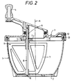
- Fig. 2 shows a cross-section of the device of Fig. 1;
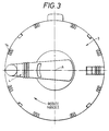
- Fig. 3 shows a plan view of the device of Fig. 1;
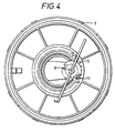
- Fig. 4 shows the gear mechanism of the device of Fig. 1; and
- Fig. 5 shows a cross-section of a preferred embodiment of the mixing device including an integral valve/filter assembly.
- Referring to Figs. 1 to 5, the mixing device comprises a
mixing bowl 1 having abase 2 and an open top. Alid 3 is adapted to fit and seal the top of thebowl 1. Thelid 3 is provided with ahandle 4, rotatably mounted in, and extending outwardly from thelid 3. The under side of the lid is provided with a fixed, circular,toothed rack 5 which is coaxially arranged with respect to the rotation axis A of the handle. Asocket 6 is provided in the underside of thehandle 4, eccentrically with respect to the central axis A. The device also includes a mixingpaddle 7 mounted on anaxle 8 supportingmixing vanes 9 extending outwardly therefrom. Theaxle 8 is rotatably mounted, at one end, in thesocket 6 in thehandle 4. The other end of theaxle 8 fits into acircular groove 10 around thebase 2 of thebowl 1. Acog wheel 11 is fixedly attached to the upper part of theaxle 8 for intermeshing engagement with thetoothed rack 5. Thelid 3 is also provided with avacuum port 12 for connection to a vacuum pump (not shown). Thelid 3 is preferably provided with aseal 13, for sealing between thelid 3 and the rim of thebowl 1, and locking means 14 to hold thelid 3 securely in place during mixing. - The substances to be mixed are placed in the
mixing bowl 1. Thelid 3 is then placed on the bowl and locked. Thevacuum port 12 is connected, via a length ofPVC tubing 15, to a vacuum pump (not shown) to create a vacuum in thebowl 1. The preferred operating vacuum is in the range of 0.7 to 0.9 bar, and is most preferably 0.75 bar. To mix the components, the operator rotates thehandle 4 which causes planetary movement of theaxle 8 about the central axis A and at the same time causes thecog wheel 11 to mesh with therack 5 so to drive thecog wheel 11, producing rotation of thepaddle 7 about the axis of theaxle 8. Thus, due to the gear mechanism provided by thetoothed rack 5 and thecog wheel 11, rotation of thehandle 4 causes thepaddle 7 to move around thebowl 1 in planetary fashion and, at the same time, to rotate about its own axis. Such a mechanism enables thepaddle 7 to rotate several times for each turn of thehandle 4 and results in a more than 90% coverage of the bowl area. One rotation of thehandle 4 does not cause a whole number of rotations of thepaddle 7, such that thepaddle 7 is in a different orientation at the beginning and end of a particular cycle of the axle movement; this helps to avoid dead spots being formed in the cement and improves mixing. - At least one of the
vanes 9 should extend from theaxle 8 to the wall of thebowl 1;other vanes 9 may only extend partway across thebowl 1. - The base of the
axle 8 travels around thebowl 1 in agroove 10 provided in thebase 2 of the bowl to provide support, strength and stability to thepaddle 7. Thegroove 10 ensures that thepaddle 7 always remains upright and does not bend when the cement becomes thick. - The
mixing bowl 1 is preferably made of clear plastic to enable the user to observe the progress of the cement as it is mixed. - During mixing, the noxious methylmethacrylate fumes are drawn off through the
PVC tubing 15 and filtered. This may be done in the conventional way via a one-way valve 16, which prevents the fumes returning to thebowl 1, and an activatedcharcoal filter 17. Alternatively an integrated valve/filter assembly could be used which comprises a non-woven fibre material impregnated with activated charcoal. This is a much more efficient and convenient system which does not involve the use of charcoal granules. - When the cement is ready, the
lid 3 is removed and the cement may be directly applied to the bone site by hand or may be transferred to a syringe for syringe application as preferred.
Claims (10)
- A hand-held mixing device for bone cement or the like, comprising an enclosed mixing chamber (1), a lid (3) which fits over said chamber (1), a port (12) in a wall of said chamber for connection to a vacuum source in use to enable a vacuum to be created in said chamber (1), a mixing paddle (7) extending into said chamber (1), and a rotatable handle (4) coupled to said paddle (7) by a gear mechanism (5, 11) arranged such that rotation of said handle (4) causes said paddle (7) to rotate about its own axis; characterised in that said paddle (7) is carried by an axle which is eccentrically coupled to the handle (4) such that rotation of said handle (4) also moves the axis of rotation of the paddle (7) within the chamber (1), whereby the paddle is moved around substantially the entire cement containing region of the interior of the chamber (1), and wherein the number of rotations of the paddle (7) about its own axis produced by a single rotation of the handle is not a whole number so that the paddle ends up in a different orientation after each single full rotation of the handle (4).
- A hand-held mixing device as claimed in claim 1 wherein the device is in the form of a bowl (1).
- A hand-held mixing device as claimed in claim 1 or 2 wherein said gear mechanism (5, 11) is a step-up gear such that a single rotation of the handle (4) produces a plurality of rotations of the paddle (7) about its own axis.
- A hand-held mixing device as claimed in any preceding claim further comprising locking means (14) for securely holding said lid (3) in place during mixing.
- A hand-held mixing device as claimed in any preceding claim wherein said handle (4) is rotatably mounted in the lid (3) and extends outwardly therefrom to be rotated by the user.
- A hand-held mixing device as claimed in any preceding claim further comprising a circular rack (5) fixed to the underside of the lid (3), and arranged coaxially with the rotation axis of the handle (4) which drivingly co-operates with a cog wheel (11) which drives the paddle axle to rotate the paddle (7) as the handle (4) is turned.
- A hand-held mixing device as claimed in any preceding claim wherein said mixing paddle (7) comprises a shaft (8) and at least one vane (9) extending outwardly from the shaft, wherein such vane (9) extends out to the edge of the chamber and conforms to the shape of the interior of said chamber.
- A hand-held mixing device as claimed in any preceding claim further comprising a guide groove (10) in the base of the chamber in which the base of the paddle (7), or an axle carrying the paddle, is supported as it rotates around the chamber.
- A hand-held mixing device as claimed in any preceding claim wherein said chamber is at least partly transparent.
- The use of a device as claimed in any of claims 1 to 9 in the mixing of bone cement.
Applications Claiming Priority (3)
| Application Number | Priority Date | Filing Date | Title |
|---|---|---|---|
| GB9126011 | 1991-12-06 | ||
| GB919126011A GB9126011D0 (en) | 1991-12-06 | 1991-12-06 | Bone cement mixing device |
| PCT/GB1992/002259 WO1993010892A1 (en) | 1991-12-06 | 1992-12-04 | Bone cement mixing device |
Publications (2)
| Publication Number | Publication Date |
|---|---|
| EP0616552A1 EP0616552A1 (en) | 1994-09-28 |
| EP0616552B1 true EP0616552B1 (en) | 1997-08-13 |
Family
ID=10705843
Family Applications (1)
| Application Number | Title | Priority Date | Filing Date |
|---|---|---|---|
| EP92924790A Expired - Lifetime EP0616552B1 (en) | 1991-12-06 | 1992-12-04 | Bone cement mixing device |
Country Status (9)
| Country | Link |
|---|---|
| US (1) | US5494349A (en) |
| EP (1) | EP0616552B1 (en) |
| JP (1) | JP3247698B2 (en) |
| AU (1) | AU656446B2 (en) |
| CA (1) | CA2125165C (en) |
| DE (1) | DE69221636T2 (en) |
| ES (1) | ES2107556T3 (en) |
| GB (2) | GB9126011D0 (en) |
| WO (1) | WO1993010892A1 (en) |
Cited By (1)
| Publication number | Priority date | Publication date | Assignee | Title |
|---|---|---|---|---|
| US6254268B1 (en) | 1999-07-16 | 2001-07-03 | Depuy Orthopaedics, Inc. | Bone cement mixing apparatus |
Families Citing this family (51)
| Publication number | Priority date | Publication date | Assignee | Title |
|---|---|---|---|---|
| WO1995001832A1 (en) * | 1993-07-06 | 1995-01-19 | Earle Michael L | Automated bone cement mixing apparatus |
| US5348391A (en) * | 1993-11-16 | 1994-09-20 | Murray William M | Manual bone cement mixing method |
| USD381084S (en) * | 1995-05-19 | 1997-07-15 | Smith & Nephew Richards Inc. | Cement mixer |
| US5549381A (en) * | 1995-05-19 | 1996-08-27 | Hays; Greta J. | Method and apparatus for mixing polymeric bone cement components |
| US5797678A (en) * | 1995-09-25 | 1998-08-25 | Murray; William M. | Bone cement mixing device and method |
| US5788463A (en) * | 1995-12-22 | 1998-08-04 | Chan; Kwan-Ho | Manual vacuum producing system having pressure indicator |
| US5797680A (en) * | 1996-09-05 | 1998-08-25 | Murray; William M. | Manual bone cement mixing system with vacuum pump start-stop device |
| US6033105A (en) * | 1996-11-15 | 2000-03-07 | Barker; Donald | Integrated bone cement mixing and dispensing system |
| US5876116A (en) * | 1996-11-15 | 1999-03-02 | Barker; Donald | Integrated bone cement mixing and dispensing system |
| IL128261A0 (en) * | 1999-01-27 | 1999-11-30 | Disc O Tech Medical Tech Ltd | Expandable element |
| US20070282443A1 (en) * | 1997-03-07 | 2007-12-06 | Disc-O-Tech Medical Technologies Ltd. | Expandable element |
| WO1999037256A1 (en) * | 1998-01-21 | 1999-07-29 | Immedica | Bone cement mixer and dispenser |
| US7621950B1 (en) | 1999-01-27 | 2009-11-24 | Kyphon Sarl | Expandable intervertebral spacer |
| GB2352408B (en) | 1999-07-27 | 2001-07-11 | Summit Medical Ltd | Orthopaedic bone cement mixing container |
| GB2359762B (en) * | 2000-01-31 | 2003-03-12 | Summit Medical Ltd | Orthopaedic cement mixing device |
| US20020191487A1 (en) * | 2000-10-25 | 2002-12-19 | Kyphon Inc. | Systems and methods for mixing and transferring flowable materials |
| US6702455B2 (en) * | 2000-12-01 | 2004-03-09 | Depuy Orthopaedics, Inc. | Bone cement mixing apparatus having improved gearing arrangement for driving a mixing blade |
| US6655828B2 (en) | 2000-12-01 | 2003-12-02 | Depuy Orthopaedics, Inc. | Bone cement mixing apparatus having improved mixing blade configuration |
| US6945688B2 (en) * | 2001-01-10 | 2005-09-20 | Stryker Instruments | Container assembly for mixing materials |
| US20020110046A1 (en) * | 2001-01-19 | 2002-08-15 | Robertson James F. | Fluid agitator and conditioner |
| US7008433B2 (en) * | 2001-02-15 | 2006-03-07 | Depuy Acromed, Inc. | Vertebroplasty injection device |
| CN1835720B (en) * | 2001-07-25 | 2011-09-28 | Disc整形外科技术股份有限公司 | Deformable tools and implants |
| JP4663238B2 (en) * | 2002-03-14 | 2011-04-06 | ストライカー コーポレイション | Mixer assembly for mixing bone cement |
| US6921192B2 (en) * | 2002-03-29 | 2005-07-26 | Depuy Orthopaedics, Inc. | Bone cement mixing apparatus |
| SE0201180L (en) * | 2002-04-18 | 2003-02-18 | Cemvac System Ab | Apparatus for preparing bone cement comprising a mixing bowl with a sealing cap, in which at least one rotatable mixing element is stored |
| GB2398741B (en) * | 2003-02-05 | 2005-04-13 | Summit Medical Ltd | Orthopaedic cement mixing device |
| US20060264967A1 (en) | 2003-03-14 | 2006-11-23 | Ferreyro Roque H | Hydraulic device for the injection of bone cement in percutaneous vertebroplasty |
| US8066713B2 (en) | 2003-03-31 | 2011-11-29 | Depuy Spine, Inc. | Remotely-activated vertebroplasty injection device |
| WO2006011152A2 (en) | 2004-06-17 | 2006-02-02 | Disc-O-Tech Medical Technologies, Ltd. | Methods for treating bone and other tissue |
| US8415407B2 (en) | 2004-03-21 | 2013-04-09 | Depuy Spine, Inc. | Methods, materials, and apparatus for treating bone and other tissue |
| US20070032567A1 (en) * | 2003-06-17 | 2007-02-08 | Disc-O-Tech Medical | Bone Cement And Methods Of Use Thereof |
| US8579908B2 (en) | 2003-09-26 | 2013-11-12 | DePuy Synthes Products, LLC. | Device for delivering viscous material |
| US20050105384A1 (en) * | 2003-11-18 | 2005-05-19 | Scimed Life Systems, Inc. | Apparatus for mixing and dispensing a multi-component bone cement |
| US7524103B2 (en) * | 2003-11-18 | 2009-04-28 | Boston Scientific Scimed, Inc. | Apparatus for mixing and dispensing a multi-component bone cement |
| US7317331B2 (en) * | 2004-11-08 | 2008-01-08 | Tabula, Inc. | Reconfigurable IC that has sections running at different reconfiguration rates |
| US8029183B2 (en) * | 2005-02-23 | 2011-10-04 | Biomet Manufacturing Corp. | Apparatus for mixing bone cement |
| US9381024B2 (en) * | 2005-07-31 | 2016-07-05 | DePuy Synthes Products, Inc. | Marked tools |
| US9918767B2 (en) | 2005-08-01 | 2018-03-20 | DePuy Synthes Products, Inc. | Temperature control system |
| US8360629B2 (en) * | 2005-11-22 | 2013-01-29 | Depuy Spine, Inc. | Mixing apparatus having central and planetary mixing elements |
| US9642932B2 (en) | 2006-09-14 | 2017-05-09 | DePuy Synthes Products, Inc. | Bone cement and methods of use thereof |
| WO2008047371A2 (en) | 2006-10-19 | 2008-04-24 | Depuy Spine, Inc. | Fluid delivery system |
| US20100274246A1 (en) * | 2007-05-10 | 2010-10-28 | Oren Globerman | Expandable intramedullary nail for small bone fixation |
| CA2694558C (en) * | 2007-07-25 | 2014-06-03 | Depuy Spine, Inc. | Expandable bone filler materials and methods of using same |
| US8317800B2 (en) * | 2008-04-22 | 2012-11-27 | Warsaw Orthopedic, Inc. | Injectable material delivery device with an integrated mixer |
| GB2514535A (en) | 2013-03-18 | 2014-12-03 | Summit Medical Ltd | An apparatus for mixing and delivering bone cement |
| CN103565501A (en) * | 2013-11-26 | 2014-02-12 | 广州佳林医疗用品制造有限公司 | Bone cement stirrer |
| KR101645576B1 (en) * | 2014-10-01 | 2016-08-05 | 백은정 | Bone Cement Mixing Device |
| CN106313308A (en) * | 2016-08-31 | 2017-01-11 | 天津豹鸣股份有限公司 | Cement rotary stirring device |
| US11344855B2 (en) | 2019-07-09 | 2022-05-31 | Vivex Biologics Group, Inc. | Mixing container and method of use |
| KR102336584B1 (en) * | 2019-09-30 | 2021-12-07 | 황민석 | Bone cement mixing and injection apparatus |
| CN110743434A (en) * | 2019-10-12 | 2020-02-04 | 安徽恒明工程技术有限公司 | Processing system suitable for grain processing |
Family Cites Families (9)
| Publication number | Priority date | Publication date | Assignee | Title |
|---|---|---|---|---|
| GB178572A (en) * | 1921-01-21 | 1922-04-21 | James Harold Williams | Improvements in vessels for containing and spraying paints, varnishes, and the like |
| GB517340A (en) * | 1938-07-25 | 1940-01-26 | B B Chem Co Ltd | Improvements in or relating to stirring or agitating of the contents of cans or the like |
| US3640510A (en) * | 1969-09-26 | 1972-02-08 | Degussa | Vacuum stirring device for dental materials |
| CA1021767A (en) * | 1974-01-11 | 1977-11-29 | Samuel J. Popeil | Orbital whipper having rotatable beaters |
| JPS5388259A (en) * | 1977-01-14 | 1978-08-03 | Tokyo Electric Co Ltd | Stirring apparatus |
| US4185072A (en) * | 1977-02-17 | 1980-01-22 | Diemolding Corporation | Orthopedic cement mixer |
| SE450545B (en) * | 1984-10-19 | 1987-07-06 | Mit Ab | PROCEDURE AND DEVICE FOR MANUFACTURING BENCEMENT FOR FIXING PROSTHESIS |
| US4961647A (en) * | 1986-04-04 | 1990-10-09 | Dhd Medical Products | Orthopedic cement mixer |
| FR2597321A1 (en) * | 1986-04-22 | 1987-10-23 | Vivalp | Electric household appliance for preparing sauces |
-
1991
- 1991-12-06 GB GB919126011A patent/GB9126011D0/en active Pending
-
1992
- 1992-12-04 ES ES92924790T patent/ES2107556T3/en not_active Expired - Lifetime
- 1992-12-04 GB GB9411556A patent/GB2276560B/en not_active Expired - Lifetime
- 1992-12-04 JP JP50998093A patent/JP3247698B2/en not_active Expired - Lifetime
- 1992-12-04 CA CA002125165A patent/CA2125165C/en not_active Expired - Lifetime
- 1992-12-04 AU AU30900/92A patent/AU656446B2/en not_active Expired
- 1992-12-04 WO PCT/GB1992/002259 patent/WO1993010892A1/en active IP Right Grant
- 1992-12-04 EP EP92924790A patent/EP0616552B1/en not_active Expired - Lifetime
- 1992-12-04 DE DE69221636T patent/DE69221636T2/en not_active Expired - Lifetime
- 1992-12-04 US US08/244,642 patent/US5494349A/en not_active Expired - Lifetime
Cited By (1)
| Publication number | Priority date | Publication date | Assignee | Title |
|---|---|---|---|---|
| US6254268B1 (en) | 1999-07-16 | 2001-07-03 | Depuy Orthopaedics, Inc. | Bone cement mixing apparatus |
Also Published As
| Publication number | Publication date |
|---|---|
| CA2125165C (en) | 2003-12-02 |
| GB9126011D0 (en) | 1992-02-05 |
| GB2276560B (en) | 1995-08-09 |
| WO1993010892A1 (en) | 1993-06-10 |
| JP3247698B2 (en) | 2002-01-21 |
| GB9411556D0 (en) | 1994-08-03 |
| AU3090092A (en) | 1993-06-28 |
| EP0616552A1 (en) | 1994-09-28 |
| AU656446B2 (en) | 1995-02-02 |
| DE69221636T2 (en) | 1997-12-18 |
| ES2107556T3 (en) | 1997-12-01 |
| GB2276560A (en) | 1994-10-05 |
| CA2125165A1 (en) | 1993-06-10 |
| DE69221636D1 (en) | 1997-09-18 |
| JPH07506288A (en) | 1995-07-13 |
| US5494349A (en) | 1996-02-27 |
Similar Documents
| Publication | Publication Date | Title |
|---|---|---|
| EP0616552B1 (en) | Bone cement mixing device | |
| EP1483044B1 (en) | Mixing assembly for mixing bone cement | |
| JP3686844B2 (en) | Bone cement mixing apparatus and mixing method | |
| AU740212B2 (en) | Apparatus for storing, mixing, and dispensing two-component bone cement | |
| US5549381A (en) | Method and apparatus for mixing polymeric bone cement components | |
| EP1210974B1 (en) | Bone cement mixing apparatus having particular mixing blade configuration | |
| EP1210975B1 (en) | Bone cement mixing apparatus with gearing arrangement for driving a mixing blade | |
| EP1348479B1 (en) | Bone cement mixing apparatus | |
| EP1257237B1 (en) | Orthopaedic cement mixing device | |
| EP1494792A1 (en) | Device at a mixing container for preparation of bone cement | |
| AU773547B2 (en) | Orthopaedic bone cement mixing container |
Legal Events
| Date | Code | Title | Description |
|---|---|---|---|
| PUAI | Public reference made under article 153(3) epc to a published international application that has entered the european phase |
Free format text: ORIGINAL CODE: 0009012 |
|
| AK | Designated contracting states |
Kind code of ref document: A1 Designated state(s): BE DE ES FR IE IT NL PT SE |
|
| 17P | Request for examination filed |
Effective date: 19940704 |
|
| 17Q | First examination report despatched |
Effective date: 19950425 |
|
| GRAG | Despatch of communication of intention to grant |
Free format text: ORIGINAL CODE: EPIDOS AGRA |
|
| GRAH | Despatch of communication of intention to grant a patent |
Free format text: ORIGINAL CODE: EPIDOS IGRA |
|
| RBV | Designated contracting states (corrected) |
Designated state(s): BE DE ES FR IE IT NL PT SE |
|
| GRAH | Despatch of communication of intention to grant a patent |
Free format text: ORIGINAL CODE: EPIDOS IGRA |
|
| GRAA | (expected) grant |
Free format text: ORIGINAL CODE: 0009210 |
|
| AK | Designated contracting states |
Kind code of ref document: B1 Designated state(s): BE DE ES FR IE IT NL PT SE |
|
| ET | Fr: translation filed | ||
| REF | Corresponds to: |
Ref document number: 69221636 Country of ref document: DE Date of ref document: 19970918 |
|
| ITF | It: translation for a ep patent filed |
Owner name: ING. C. GREGORJ S.P.A. |
|
| REG | Reference to a national code |
Ref country code: ES Ref legal event code: FG2A Ref document number: 2107556 Country of ref document: ES Kind code of ref document: T3 |
|
| REG | Reference to a national code |
Ref country code: PT Ref legal event code: SC4A Free format text: AVAILABILITY OF NATIONAL TRANSLATION Effective date: 19970930 |
|
| PLBE | No opposition filed within time limit |
Free format text: ORIGINAL CODE: 0009261 |
|
| STAA | Information on the status of an ep patent application or granted ep patent |
Free format text: STATUS: NO OPPOSITION FILED WITHIN TIME LIMIT |
|
| 26N | No opposition filed | ||
| REG | Reference to a national code |
Ref country code: ES Ref legal event code: PC2A |
|
| REG | Reference to a national code |
Ref country code: PT Ref legal event code: PD4A Free format text: SUMMIT MEDICAL LIMITED GB Effective date: 20020822 Ref country code: PT Ref legal event code: PC4A Free format text: SUMMIT MEDICAL (HOLDINGS) LIMITED GB Effective date: 20020822 |
|
| REG | Reference to a national code |
Ref country code: FR Ref legal event code: TP Ref country code: FR Ref legal event code: CD |
|
| BECN | Be: change of holder's name |
Owner name: *SUMMIT MEDICAL LTD Effective date: 20030107 |
|
| NLS | Nl: assignments of ep-patents |
Owner name: SUMMIT MEDICAL (HOLDINGS) LIMITED |
|
| REG | Reference to a national code |
Ref country code: FR Ref legal event code: GC |
|
| PGFP | Annual fee paid to national office [announced via postgrant information from national office to epo] |
Ref country code: IT Payment date: 20101230 Year of fee payment: 19 |
|
| PGFP | Annual fee paid to national office [announced via postgrant information from national office to epo] |
Ref country code: PT Payment date: 20111107 Year of fee payment: 20 Ref country code: SE Payment date: 20111221 Year of fee payment: 20 Ref country code: FR Payment date: 20111221 Year of fee payment: 20 Ref country code: ES Payment date: 20111216 Year of fee payment: 20 Ref country code: IE Payment date: 20111130 Year of fee payment: 20 Ref country code: NL Payment date: 20111228 Year of fee payment: 20 |
|
| PGFP | Annual fee paid to national office [announced via postgrant information from national office to epo] |
Ref country code: DE Payment date: 20111221 Year of fee payment: 20 |
|
| PGFP | Annual fee paid to national office [announced via postgrant information from national office to epo] |
Ref country code: BE Payment date: 20120102 Year of fee payment: 20 |
|
| REG | Reference to a national code |
Ref country code: DE Ref legal event code: R071 Ref document number: 69221636 Country of ref document: DE |
|
| REG | Reference to a national code |
Ref country code: DE Ref legal event code: R071 Ref document number: 69221636 Country of ref document: DE |
|
| REG | Reference to a national code |
Ref country code: NL Ref legal event code: V4 Effective date: 20121204 Ref country code: PT Ref legal event code: MM4A Free format text: MAXIMUM VALIDITY LIMIT REACHED Effective date: 20121204 |
|
| BE20 | Be: patent expired |
Owner name: *SUMMIT MEDICAL LTD Effective date: 20121204 |
|
| REG | Reference to a national code |
Ref country code: SE Ref legal event code: EUG |
|
| PG25 | Lapsed in a contracting state [announced via postgrant information from national office to epo] |
Ref country code: PT Free format text: LAPSE BECAUSE OF EXPIRATION OF PROTECTION Effective date: 20121212 |
|
| REG | Reference to a national code |
Ref country code: ES Ref legal event code: FD2A Effective date: 20130718 |
|
| PG25 | Lapsed in a contracting state [announced via postgrant information from national office to epo] |
Ref country code: ES Free format text: LAPSE BECAUSE OF EXPIRATION OF PROTECTION Effective date: 20121205 |
|
| REG | Reference to a national code |
Ref country code: IE Ref legal event code: MM4A |
|
| PG25 | Lapsed in a contracting state [announced via postgrant information from national office to epo] |
Ref country code: IE Free format text: LAPSE BECAUSE OF EXPIRATION OF PROTECTION Effective date: 20121204 |