EP0618458B1 - Nuclear magnetic resonance measuring apparatus - Google Patents
Nuclear magnetic resonance measuring apparatus Download PDFInfo
- Publication number
- EP0618458B1 EP0618458B1 EP94400714A EP94400714A EP0618458B1 EP 0618458 B1 EP0618458 B1 EP 0618458B1 EP 94400714 A EP94400714 A EP 94400714A EP 94400714 A EP94400714 A EP 94400714A EP 0618458 B1 EP0618458 B1 EP 0618458B1
- Authority
- EP
- European Patent Office
- Prior art keywords
- magnet
- magnet assemblies
- magnetic field
- logging device
- borehole
- Prior art date
- Legal status (The legal status is an assumption and is not a legal conclusion. Google has not performed a legal analysis and makes no representation as to the accuracy of the status listed.)
- Expired - Lifetime
Links
- 238000005481 NMR spectroscopy Methods 0.000 title claims description 18
- 230000000712 assembly Effects 0.000 claims description 17
- 238000000429 assembly Methods 0.000 claims description 17
- 230000003068 static effect Effects 0.000 claims description 16
- 230000015572 biosynthetic process Effects 0.000 claims description 15
- 238000005755 formation reaction Methods 0.000 claims description 15
- RYGMFSIKBFXOCR-UHFFFAOYSA-N Copper Chemical compound [Cu] RYGMFSIKBFXOCR-UHFFFAOYSA-N 0.000 claims description 9
- 239000004020 conductor Substances 0.000 claims description 9
- 239000003990 capacitor Substances 0.000 claims description 8
- 229910052761 rare earth metal Inorganic materials 0.000 claims description 7
- 150000002910 rare earth metals Chemical class 0.000 claims description 7
- 229910052751 metal Inorganic materials 0.000 claims description 5
- 239000002184 metal Substances 0.000 claims description 5
- 229910052802 copper Inorganic materials 0.000 claims description 3
- 239000010949 copper Substances 0.000 claims description 3
- 239000011888 foil Substances 0.000 claims description 2
- 239000010410 layer Substances 0.000 claims 2
- 239000011229 interlayer Substances 0.000 claims 1
- 238000005259 measurement Methods 0.000 description 7
- 229910000859 α-Fe Inorganic materials 0.000 description 7
- 238000013459 approach Methods 0.000 description 6
- 239000011889 copper foil Substances 0.000 description 6
- 238000011835 investigation Methods 0.000 description 6
- 230000005415 magnetization Effects 0.000 description 6
- 239000000463 material Substances 0.000 description 6
- UFHFLCQGNIYNRP-UHFFFAOYSA-N Hydrogen Chemical compound [H][H] UFHFLCQGNIYNRP-UHFFFAOYSA-N 0.000 description 4
- 238000010586 diagram Methods 0.000 description 4
- 239000012530 fluid Substances 0.000 description 4
- 229910052739 hydrogen Inorganic materials 0.000 description 4
- 239000001257 hydrogen Substances 0.000 description 4
- 239000000696 magnetic material Substances 0.000 description 4
- 230000006870 function Effects 0.000 description 3
- 229910000792 Monel Inorganic materials 0.000 description 2
- 239000004677 Nylon Substances 0.000 description 2
- RTAQQCXQSZGOHL-UHFFFAOYSA-N Titanium Chemical compound [Ti] RTAQQCXQSZGOHL-UHFFFAOYSA-N 0.000 description 2
- 230000008901 benefit Effects 0.000 description 2
- 238000013016 damping Methods 0.000 description 2
- 238000005553 drilling Methods 0.000 description 2
- 229920001778 nylon Polymers 0.000 description 2
- 239000002245 particle Substances 0.000 description 2
- 239000011435 rock Substances 0.000 description 2
- 239000007787 solid Substances 0.000 description 2
- 239000000126 substance Substances 0.000 description 2
- 239000010936 titanium Substances 0.000 description 2
- 229910052719 titanium Inorganic materials 0.000 description 2
- 230000005540 biological transmission Effects 0.000 description 1
- 239000000470 constituent Substances 0.000 description 1
- 230000008878 coupling Effects 0.000 description 1
- 238000010168 coupling process Methods 0.000 description 1
- 238000005859 coupling reaction Methods 0.000 description 1
- 238000001514 detection method Methods 0.000 description 1
- 230000002500 effect on skin Effects 0.000 description 1
- 229930195733 hydrocarbon Natural products 0.000 description 1
- 150000002430 hydrocarbons Chemical class 0.000 description 1
- 239000011810 insulating material Substances 0.000 description 1
- 230000007246 mechanism Effects 0.000 description 1
- 239000007769 metal material Substances 0.000 description 1
- 238000004806 packaging method and process Methods 0.000 description 1
- 230000035699 permeability Effects 0.000 description 1
- 230000010287 polarization Effects 0.000 description 1
- 239000011148 porous material Substances 0.000 description 1
- 230000035945 sensitivity Effects 0.000 description 1
- 239000000725 suspension Substances 0.000 description 1
- XLYOFNOQVPJJNP-UHFFFAOYSA-N water Substances O XLYOFNOQVPJJNP-UHFFFAOYSA-N 0.000 description 1
Images


Classifications
-
- G—PHYSICS
- G01—MEASURING; TESTING
- G01R—MEASURING ELECTRIC VARIABLES; MEASURING MAGNETIC VARIABLES
- G01R33/00—Arrangements or instruments for measuring magnetic variables
- G01R33/20—Arrangements or instruments for measuring magnetic variables involving magnetic resonance
- G01R33/28—Details of apparatus provided for in groups G01R33/44 - G01R33/64
- G01R33/38—Systems for generation, homogenisation or stabilisation of the main or gradient magnetic field
- G01R33/3808—Magnet assemblies for single-sided MR wherein the magnet assembly is located on one side of a subject only; Magnet assemblies for inside-out MR, e.g. for MR in a borehole or in a blood vessel, or magnet assemblies for fringe-field MR
-
- G—PHYSICS
- G01—MEASURING; TESTING
- G01R—MEASURING ELECTRIC VARIABLES; MEASURING MAGNETIC VARIABLES
- G01R33/00—Arrangements or instruments for measuring magnetic variables
- G01R33/20—Arrangements or instruments for measuring magnetic variables involving magnetic resonance
- G01R33/28—Details of apparatus provided for in groups G01R33/44 - G01R33/64
- G01R33/32—Excitation or detection systems, e.g. using radio frequency signals
- G01R33/34—Constructional details, e.g. resonators, specially adapted to MR
-
- G—PHYSICS
- G01—MEASURING; TESTING
- G01V—GEOPHYSICS; GRAVITATIONAL MEASUREMENTS; DETECTING MASSES OR OBJECTS; TAGS
- G01V3/00—Electric or magnetic prospecting or detecting; Measuring magnetic field characteristics of the earth, e.g. declination, deviation
- G01V3/18—Electric or magnetic prospecting or detecting; Measuring magnetic field characteristics of the earth, e.g. declination, deviation specially adapted for well-logging
- G01V3/32—Electric or magnetic prospecting or detecting; Measuring magnetic field characteristics of the earth, e.g. declination, deviation specially adapted for well-logging operating with electron or nuclear magnetic resonance
Definitions
- This invention relates to determination of nuclear magnetic resonance properties of substances, and has particular application to determination of nuclear magnetic resonance properties of earth formations surrounding a borehole.
- NMR nuclear magnetic resonance
- any particles of a formation having non-zero magnetic spin for example protons
- a magnetic field may be naturally generated, as is the case for the earth's magnetic field, B E .
- B 1 the earth's magnetic field
- the protons will align with the vector sum of B E and B 1 after a sufficient polarization time has passed. If the polarizing field B 1 is then switched off, the protons will tend to precess about the B E vector with a characteristic Larmor frequency ⁇ L which depends on the strength of the earth's field B E and the gyromagnetic constant of the particle.
- Hydrogen nuclei precessing about a magnetic field B E of 0.5 x 10 -4 T have a characteristic frequency of approximately 2 kHz. If a population of hydrogen nuclei were made to precess in phase, the combined magnetic fields of the protons can generate a detectable oscillating voltage in a receiver coil. Hydrogen nuclei (protons) of water and hydrocarbons occurring in rock pores produce NMR signals distinct from signals induced in other rock constituents.
- a further NMR approach employs a locally generated static magnetic field, B 0 , which may be produced by one or more permanent magnets. Nuclear spins align with the applied field B 0 with a time constant of T 1 . The angle between the nuclear magnetization and the applied field can be changed by applying an RF magnetic field B 1 perpendicular to the static field B 0 . The frequency of the RF field must be (4.258 kHz/10 -4 T) . B 0 ((4.258 kHz/Gauss) . B 0 ). The angle of nutation (tilt) obtained between the nuclear magnetization and the static field is proportional to the product of B 1 and the duration of the RF pulse.
- the nuclear spins precess around the static field B 0 at the Larmor frequency (4.258 kHz/10 -4 T) .
- B 0 ((4.258 kHz/Gauss) .
- B 0 The rotating component of the nuclear magnetization decays with a time constant T 2 which is less than T 1 .
- T 2 time constant
- the RF field, B 1 perpendicular to the static field, B 0 , to have the static field, B 0 , as large as possible, and to have a static field intensity variation, as a function of position, be as small as possible in the measurement region so that a larger "resonant volume" will contribute to the measurements.
- U.S. Pat. No. 5,055,788 discloses a nuclear magnetic resonance logging device having permanent magnets and an RF trough antenna mounted in a pad or skid that contacts the borehole wall. Measurements are made on the side of the borehole wall that the pad or skid faces. Relatively powerful rare-earth magnets can be used, and are arranged to obtain a static and substantially homogeneous magnetic field in a given volume of the formation directed to one side of the body.
- the trough antenna that generates the RF field is electromagnetically shielded and is directed toward the given volume of formation.
- Another approach uses one or more cylindrically arranged permanent magnets in a centralized tool with a generally circumferential region of investigation around the borehole.
- An RF coil is wound around the outside of the magnets, and produces an RF field that is indicated as being perpendicular to the static field produced by the permanent magnets.
- a limitation of this centralized approach is that the RF magnetic field produced by the coil needs to pass through the magnet material, and the 713 Patent indicates that it is essential that the magnet material be non-conductive, such as a ferrite.
- JOURNAL OF MAGNETIC RESONANCE vol.97, no. 3, 1.5.92, p. 466- 485 "Novel NMR Apparatus for Investigating an External Sample", R. L. Kleinberg, A. Sezginer, and D. D. Griffin, describes apparatus for measuring a nuclear magnetic resonance property of formations surrounding an earth borehole comprising a logging device moveable through the borehole and first and second elongated magnets having an antenna therebetween arranged to generate a static magnetic field that extends outside the logging device into the formation and an RF field perpendicular thereto.
- the antenna is capable of sensing the precessing magnetic field in the formation in order to provide information about the formation.
- the present invention is directed to a nuclear magnetic resonance measurement apparatus that can be utilized in a logging device which operates generally centrally in a borehole, and has a generally circumferential region of investigation, but which permits usage of relatively powerful permanent magnets, such as rare-earth magnets, that are not permeable to the RF magnetic field. This is achieved by employing side-by-side spaced apart elongated magnets, and an RF current loop (or plurality of loops, as in a coil) in the region between the magnets.
- an apparatus for measuring a nuclear magnetic resonance property of formations surrounding an earth borehole comprising a logging device moveable through the borehole and first and second elongated magnet assemblies being arranged to generate a magnetic field that extends outside the logging device, each magnet assembly having a longitudinal axis and being disposed alongside one another within the logging device with a gap therebetween and the longitudinal axes parallel to one another, said first and second elongated magnet assemblies each consisting of a permanent magnet and a magnet casing; the apparatus further comprising a RF antenna arranged to generate an oscillating magnetic field that extends outside the logging device; means arranged to couple RF energy to said RF antenna; and means arranged to detect RF signals induced in said RF antenna, said apparatus being characterized in that each magnet casing has electrically conductive surfaces and that the RF antenna is a RF current loop disposed in the gap between said magnet assemblies and includes at least a portion of said conductive surfaces of said magnet casings.
- the magnets are each in the shape of a segment of a cylinder, and the respective axes of elongation of the magnets are parallel.
- the magnets have respective casings with electrically conductive surfaces
- the RF current loop includes at least a portion of the conductive surfaces of the magnet casings.
- the RF current loop includes a conductor coupled between conductive surfaces of respective magnet casing surfaces, and further includes at least one capacitor coupled between conductive surfaces of respective magnet casing surfaces.
- the permanent magnets extend longitudinally beyond both longitudinal extremes of the RF current loop. This helps ensure that the static magnetic field is relatively constant with respect to the longitudinal (generally, vertical) position in the region of investigation, and also reduces or eliminates any spurious NMR signal contribution from the borehole fluid beyond the longitudinal ends of the magnets.
- FIG. 1 is a diagram, partially in block form, of an apparatus in accordance with an embodiment of the invention.
- FIG. 2 is a cross-sectional partially broken-away and schematic view of the logging device of the FIG. 1 apparatus.
- FIG. 3 is another cross-sectional, partially broken away and schematic view of the FIG. 1 apparatus.
- FIG. 4 is a cross-sectional view as taken through a section defined by arrows 4-4 of FIG. 3.
- FIG. 5 is a diagram showing two z-independent dipolar fields that are everywhere orthogonal.
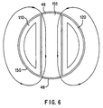
- FIG. 6 is a simplified top view of the logging device of the FIG. 1 embodiment, illustrating representative field lines of the RF magnetic field.
- FIG. 7 illustrates a partially broken-away view of the exterior of an embodiment of the logging device of FIG. 1.
- FIG. 8 is a block diagram of circuitry that can be utilized in an embodiment of the invention.
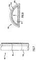
- FIG. 9 is a cross-sectional view through a layered magnet casing, in accordance with an embodiment of the invention.
- FIG. 1 there is shown an apparatus in accordance with an embodiment of the invention for investigating subsurface formations 31 traversed by a borehole 32, which can be used in practicing embodiments of the invention.
- the borehole 32 is typically filed with a drilling fluid or mud which contains finely divided solids in suspension and a mudcake 39 is shown on the walls of the borehole.
- An investigating apparatus or logging device is suspended in the borehole 32 on an armored cable 33, the length of which substantially determines the relative depth of the device 30.
- the cable length is controlled by suitable means at the surface such as a drum and winch mechanism (not shown).
- the logging device comprises an elongated cylindrical sonde 40, which can be provided with centralizing arms (not shown).
- the top portion thereof, 42 can contain electronics and telemetry equipment. Measurement signals can be processed and/or stored downhole, using a downhole processor, but it will be understood that some or all signals could be transmitted uphole for processing and/or storage.
- Electronic signals indicative of the information obtained by the logging device can be transmitted through the cable 33 to uphole telemetry equipment 80, uphole processor 85, and recorder 95.
- Depth information to the recorder 95 and processor 85 can be provided from a rotating wheel 96 that is coupled to the cable 33.
- the processor 85 will typically include associated memory, timing, input/output, display, and printing functions, none of which are separately shown.
- the logging device is shown as a single body, it may alternatively comprise separate components, or may be a tool that is combinable with other logging tools.
- a wireline is illustrated, alternative forms of physical support and communicating link can be used, for example in a measurement while drilling system.
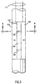
- the lower portion of the logging device 40, represented at 45 in FIG. 1, is shown, partially schematically, in FIG. 2.
- Elongated permanent magnets 110 and 120 are mounted in side-by-side spaced apart arrangement within a housing 150, shown broken away in FIG. 2.
- the longitudinal axes of the magnets are parallel and, in the present embodiment, are also parallel to the longitudinal axis of the sonde 40, which will generally be approximately parallel to the borehole axis.
- the magnetic material of the permanent magnets is part of a magnet assembly that includes a casing with a surface having one or more layers.
- the magnets are preferably rare earth magnets, such as Sm-Co magnets, which are relatively powerful permanent magnets, but which are conductive and are not permeable to the RF magnetic field.
- the rare earth magnetic material is relatively brittle, and is difficult to make in large pieces, so it is conventionally made by packaging a number of small pieces of the rare earth magnetic material in a relatively strong magnet casing.
- the magnet casing material is preferably a non-magnetic metal such as titanium or monel.
- each of the magnet casings is in the shape of a segment of an elongated cylinder.
- the magnetization directions of the magnets are aligned, and are perpendicular to the longitudinal axis of the magnets and the sonde.
- the magnetization directions are also perpendicular to the radial direction of the gap between the magnets.
- the magnet casings constitute part of an RF current loop that is used to transmit and receive the RF magnetic field.
- a conductor 125 for example a copper cable, plate, or wires, is coupled across the magnet casings, preferably at a longitudinal position below the longitudinal centers of the magnets, and above the lower ends of the magnets.
- At least one capacitor represented in FIGS. 2-4 by capacitors 135, is coupled across the magnet casings, preferably at a longitudinal position above the longitudinal centers of the magnet casings, and below the top ends of the magnet casings.
- the magnet casings (and the magnets therein) extend substantially above and below the resonant region of the RF loop.
- a ferrite core 155 (not shown in FIG. 2, for ease of illustration), which may either be a ferrite permanent magnet or an unmagnetized ferrite with high magnetic permeability, but must be permeable to the RF magnetic field, can be provided in the region between the magnets, as shown in FIGS. 3 and 4.
- Conductors from the RF transmitter/receiver, represented at 111, are coupled to the magnet casings, as shown in FIGS. 2 and 3, and with the lefthand conductor being coupled to magnet casing 110 through insulating material 113.
- the magnet casings can, for example, be bolted together, using a lower bolt (not shown) below conductor 125, and an upper bolt, such as an insulated bolt (not shown), above capacitor(s) 135, to form a sturdy and rugged structure.
- FIG. 5 illustrates the field patterns of two z-independent [z being the longitudinal (or vertical) direction] dipolar fields, represented in solid and dashed line, respectively, that are orthogonal to each other at all points. These patterns are approximately representative of the static and RF fields, respectively, in the embodiment of FIGS. 2-4.
- the solid line field pattern approximately represents the static field pattern
- the dashed line field pattern approximately represents the RF field.
- the RF field exits the sonde at one side of the ferrite 155 that is not blocked by the magnet cases, circulates around the sonde, and enters the sonde at the opposite side of the ferrite 155. This is illustrated in FIG.
- FIG. 6 shows the magnets and magnet cases 110, 120, the ferrite block 155, and representative RF field lines (with arrows).
- the region of the sonde adjacent the gap between the magnet cases can be covered with a non-metallic material, 48, that will not inhibit the RF field, for example, nylon.
- FIG. 7 shows a configuration which employs a cylindrical nylon shell 48 that covers the region of the RF loop.
- the magnets are substantially longer than the longitudinal extent of the RF loop, and extend substantially above and below the RF loop (defined by capacitors 135 and RF short 125, in this embodiment).
- the length of each extension, or "guard section” is at least equal to the radial depth of investigation of the logging device.
- the upper and lower “guard sections” of the magnets are useful in providing a longer effective source of static field in the z-direction, which results in a relatively z-invariant static field in the device's investigation region around the RF loop.
- An important advantage of the guard sections is in reducing or eliminating any spurious NMR signal contribution from the borehole fluid beyond the longitudinal ends of the magnets.
- the resonant region in the borehole must be sufficiently far away from the RF loop so that no significant NMR signal is received from the borehole fluid which generally has a higher concentration of hydrogen nuclei compared to the formation.
- the guard sections of the magnets push the resonant region of the borehole away from the RF loop.
- a transmitter section includes an oscillator, represented at 810.
- An output of the oscillator is coupled to a pulse former 815, the output of which is coupled to a power amplifier 818.
- the output of power amplifier 818 is coupled to a duplexer 820 which, in turn, is coupled to the input/output leads 111 of the RF coil.
- the duplexer 820 is also coupled to a receiving section that includes an amplifier 832, a phase sensitive detector 835, which also receives the oscillator output, and an analog-to-digital converter 840.
- analog-to-digital converter 840 is coupled to a downhole processor 850, which may typically be a digital processor with associated memory, timing, and input/output circuitry.
- Timing circuitry is also separately represented at 852, and is coupled with pulse former 815, duplexer 820, and analog-to-digital converter 840.
- a Q-switch 860 is provided, and also receives timing information from timing circuit 852.
- Telemetry circuity 870 is conventionally provided for communicating with the earth's surface.
- the nuclear magnetic resonance circuitry can operate in three modes: transmitting, damping, and receiving.
- the transmitter section generates relatively large RF power of the order of 1 kilowatt at a frequency of the order of 1 MHz for a short precisely timed period, shut off this current very quickly, within about 10 microseconds, and then isolate any signals or noise of the power circuits from coupling with detection circuitry.
- the system operates with a high Q, which can result in undesirable ringing.
- the Q-switch 860 is provided to reduce this problem.
- the Q switch closes a circuit at the appropriate time, which changes the impedance seen by conductors 111 so that the system is critically damped, and ringing energy is quickly dissipated.
- the duplexer 820 protects the receiver section from high power pulses during the transmitting and damping modes. During the receiving mode the duplexer couples the RF loop antenna to the receiver amplifier 832. The amplified signal is coupled to phase sensitive detector 835, which also receives a reference signal from oscillator 810 that controls the frequency of sensitivity of the detector 835. The detected signals is converted to digital form by circuit 840, and coupled to processor 850. Ultimate transmission to the earth's surface for further known processing is implemented by circuitry 870. Reference can be made to the above noted U.S. Pat. Nos. 4,933,638, 5,055,787, and 5,055,788 for further details of circuitry and operation.
- the magnet casings are layered structures that are advantageous in providing highly conductive current paths and in also reducing induced ultrasonic vibrations that can cause spurious electronic signals in the RF output.
- FIG. 9 shows a horizontal cross section through one of the magnet assemblies, 120.
- the magnet material 911 comprises a rare-earth magnet material such as Sm-Co, contained within a structural casing 915 formed of a non-magnetic material, such as the metal titanium or monel.
- a rubber layer 916 covers the structural casing 915, and a conductive metal foil 920, such as a copper foil, covers the rubber layer.
- the copper foil can carry the RF current. Because of the skin effect, RF current flows on the outer surfaces of conductors. For example, at 1 Mhz the skin depth in a copper conductor is 0.065 mm. Therefore, a copper foil can sufficiently carry the RF current.
- the layer of rubber between the copper foil and the structural magnet casing is useful in preventing the RF-indicated forces on the copper foil from setting up ultrasonic reverberations in the magnet or in the magnet cases 915.
- the copper foil itself is too thin to support ultrasonic resonances. In this regard, reference can be made to U.S. Pat. No. 5,153,514.
Description
- This invention relates to determination of nuclear magnetic resonance properties of substances, and has particular application to determination of nuclear magnetic resonance properties of earth formations surrounding a borehole.
- There have been various prior approaches suggested and/or implemented for measuring nuclear magnetic resonance ("NMR") properties of earth formations surrounding a borehole to obtain evidence of the substances present.
- It is well recognized that any particles of a formation having non-zero magnetic spin, for example protons, have a tendency to align with a magnetic field imposed on the formation. Such a magnetic field may be naturally generated, as is the case for the earth's magnetic field, BE. When a second magnetic field B1, transverse to BE, is imposed on the protons by a logging tool electromagnet, the protons will align with the vector sum of BE and B1 after a sufficient polarization time has passed. If the polarizing field B1 is then switched off, the protons will tend to precess about the BE vector with a characteristic Larmor frequency ωL which depends on the strength of the earth's field BE and the gyromagnetic constant of the particle. Hydrogen nuclei precessing about a magnetic field BE of 0.5 x 10⁻⁴T (0.5 gauss) have a characteristic frequency of approximately 2 kHz. If a population of hydrogen nuclei were made to precess in phase, the combined magnetic fields of the protons can generate a detectable oscillating voltage in a receiver coil. Hydrogen nuclei (protons) of water and hydrocarbons occurring in rock pores produce NMR signals distinct from signals induced in other rock constituents.
- A further NMR approach employs a locally generated static magnetic field, B0, which may be produced by one or more permanent magnets. Nuclear spins align with the applied field B0 with a time constant of T1. The angle between the nuclear magnetization and the applied field can be changed by applying an RF magnetic field B1 perpendicular to the static field B0. The frequency of the RF field must be (4.258 kHz/10-4T).B0 ((4.258 kHz/Gauss).B0). The angle of nutation (tilt) obtained between the nuclear magnetization and the static field is proportional to the product of B1 and the duration of the RF pulse. At the end of the RF pulse, the nuclear spins precess around the static field B0 at the Larmor frequency (4.258 kHz/10-4T).B0 ((4.258 kHz/Gauss).B0). The rotating component of the nuclear magnetization decays with a time constant T2 which is less than T1. Various measurements, known in the art, can be made to determine parameters of these phenomena, from which earth formation characteristics can be inferred.
- For the type of operation just described, it is desirable to have the RF field, B1, perpendicular to the static field, B0, to have the static field, B0, as large as possible, and to have a static field intensity variation, as a function of position, be as small as possible in the measurement region so that a larger "resonant volume" will contribute to the measurements.
- One prior art approach is described, for example, in U.S. Pat. No. 5,055,788, which discloses a nuclear magnetic resonance logging device having permanent magnets and an RF trough antenna mounted in a pad or skid that contacts the borehole wall. Measurements are made on the side of the borehole wall that the pad or skid faces. Relatively powerful rare-earth magnets can be used, and are arranged to obtain a static and substantially homogeneous magnetic field in a given volume of the formation directed to one side of the body. The trough antenna that generates the RF field is electromagnetically shielded and is directed toward the given volume of formation.
- Another approach, described, for example, in U.S. Pat. No. 4,710,713, uses one or more cylindrically arranged permanent magnets in a centralized tool with a generally circumferential region of investigation around the borehole. An RF coil is wound around the outside of the magnets, and produces an RF field that is indicated as being perpendicular to the static field produced by the permanent magnets. A limitation of this centralized approach is that the RF magnetic field produced by the coil needs to pass through the magnet material, and the 713 Patent indicates that it is essential that the magnet material be non-conductive, such as a ferrite.
- It is among the objects of the present invention to provide a nuclear magnetic resonance measuring apparatus that has a generally circumferential region of investigation, and overcomes limitations of prior art approaches.
- JOURNAL OF MAGNETIC RESONANCE, vol.97, no. 3, 1.5.92, p. 466- 485 "Novel NMR Apparatus for Investigating an External Sample", R. L. Kleinberg, A. Sezginer, and D. D. Griffin, describes apparatus for measuring a nuclear magnetic resonance property of formations surrounding an earth borehole comprising a logging device moveable through the borehole and first and second elongated magnets having an antenna therebetween arranged to generate a static magnetic field that extends outside the logging device into the formation and an RF field perpendicular thereto. The antenna is capable of sensing the precessing magnetic field in the formation in order to provide information about the formation.
- The present invention is directed to a nuclear magnetic resonance measurement apparatus that can be utilized in a logging device which operates generally centrally in a borehole, and has a generally circumferential region of investigation, but which permits usage of relatively powerful permanent magnets, such as rare-earth magnets, that are not permeable to the RF magnetic field. This is achieved by employing side-by-side spaced apart elongated magnets, and an RF current loop (or plurality of loops, as in a coil) in the region between the magnets.
- In accordance with an embodiment of the invention, there is provided an apparatus for measuring a nuclear magnetic resonance property of formations surrounding an earth borehole comprising a logging device moveable through the borehole and first and second elongated magnet assemblies being arranged to generate a magnetic field that extends outside the logging device, each magnet assembly having a longitudinal axis and being disposed alongside one another within the logging device with a gap therebetween and the longitudinal axes parallel to one another,
said first and second elongated magnet assemblies each consisting of a permanent magnet and a magnet casing;
the apparatus further comprising a RF antenna arranged to generate an oscillating magnetic field that extends outside the logging device;
means arranged to couple RF energy to said RF antenna; and
means arranged to detect RF signals induced in said RF antenna,
said apparatus being characterized in that each magnet casing has electrically conductive surfaces and that the RF antenna is a RF current loop disposed in the gap between said magnet assemblies and includes at least a portion of said conductive surfaces of said magnet casings. - In a disclosed embodiment of the invention, the magnets are each in the shape of a segment of a cylinder, and the respective axes of elongation of the magnets are parallel. In this embodiment, the magnets have respective casings with electrically conductive surfaces, and the RF current loop includes at least a portion of the conductive surfaces of the magnet casings. Also in this embodiment, the RF current loop includes a conductor coupled between conductive surfaces of respective magnet casing surfaces, and further includes at least one capacitor coupled between conductive surfaces of respective magnet casing surfaces.
- In accordance with a further feature of the invention the permanent magnets extend longitudinally beyond both longitudinal extremes of the RF current loop. This helps ensure that the static magnetic field is relatively constant with respect to the longitudinal (generally, vertical) position in the region of investigation, and also reduces or eliminates any spurious NMR signal contribution from the borehole fluid beyond the longitudinal ends of the magnets.
- Further features and advantages of the invention will become more readily apparent from the following detailed description when taken in conjunction with the accompanying drawings.
- FIG. 1 is a diagram, partially in block form, of an apparatus in accordance with an embodiment of the invention.
- FIG. 2 is a cross-sectional partially broken-away and schematic view of the logging device of the FIG. 1 apparatus.
- FIG. 3 is another cross-sectional, partially broken away and schematic view of the FIG. 1 apparatus.
- FIG. 4 is a cross-sectional view as taken through a section defined by arrows 4-4 of FIG. 3.
- FIG. 5 is a diagram showing two z-independent dipolar fields that are everywhere orthogonal.
- FIG. 6 is a simplified top view of the logging device of the FIG. 1 embodiment, illustrating representative field lines of the RF magnetic field.
- FIG. 7 illustrates a partially broken-away view of the exterior of an embodiment of the logging device of FIG. 1.
- FIG. 8 is a block diagram of circuitry that can be utilized in an embodiment of the invention.
- FIG. 9 is a cross-sectional view through a layered magnet casing, in accordance with an embodiment of the invention.
- Referring to FIG. 1, there is shown an apparatus in accordance with an embodiment of the invention for investigating
subsurface formations 31 traversed by aborehole 32, which can be used in practicing embodiments of the invention. Theborehole 32 is typically filed with a drilling fluid or mud which contains finely divided solids in suspension and amudcake 39 is shown on the walls of the borehole. - An investigating apparatus or logging device is suspended in the
borehole 32 on an armored cable 33, the length of which substantially determines the relative depth of the device 30. The cable length is controlled by suitable means at the surface such as a drum and winch mechanism (not shown). In the illustrated embodiment, the logging device comprises an elongatedcylindrical sonde 40, which can be provided with centralizing arms (not shown). The top portion thereof, 42, can contain electronics and telemetry equipment. Measurement signals can be processed and/or stored downhole, using a downhole processor, but it will be understood that some or all signals could be transmitted uphole for processing and/or storage. Electronic signals indicative of the information obtained by the logging device can be transmitted through the cable 33 touphole telemetry equipment 80,uphole processor 85, andrecorder 95. Depth information to therecorder 95 andprocessor 85 can be provided from arotating wheel 96 that is coupled to the cable 33. Theprocessor 85 will typically include associated memory, timing, input/output, display, and printing functions, none of which are separately shown. Although the logging device is shown as a single body, it may alternatively comprise separate components, or may be a tool that is combinable with other logging tools. Also, while a wireline is illustrated, alternative forms of physical support and communicating link can be used, for example in a measurement while drilling system. - The lower portion of the
logging device 40, represented at 45 in FIG. 1, is shown, partially schematically, in FIG. 2. Elongatedpermanent magnets housing 150, shown broken away in FIG. 2. The longitudinal axes of the magnets are parallel and, in the present embodiment, are also parallel to the longitudinal axis of thesonde 40, which will generally be approximately parallel to the borehole axis. In the present embodiment, and as described further hereinbelow, the magnetic material of the permanent magnets is part of a magnet assembly that includes a casing with a surface having one or more layers. The magnets are preferably rare earth magnets, such as Sm-Co magnets, which are relatively powerful permanent magnets, but which are conductive and are not permeable to the RF magnetic field. The rare earth magnetic material is relatively brittle, and is difficult to make in large pieces, so it is conventionally made by packaging a number of small pieces of the rare earth magnetic material in a relatively strong magnet casing. In the present embodiment the magnet casing material is preferably a non-magnetic metal such as titanium or monel. In the illustrated embodiment, each of the magnet casings is in the shape of a segment of an elongated cylinder. The magnetization directions of the magnets, represented by the arrows in the Figure, are aligned, and are perpendicular to the longitudinal axis of the magnets and the sonde. The magnetization directions are also perpendicular to the radial direction of the gap between the magnets. - According to the invention, the magnet casings constitute part of an RF current loop that is used to transmit and receive the RF magnetic field. In the embodiment illustrated in FIG. 2 (and with reference now also to FIGS. 3 and 4) a
conductor 125, for example a copper cable, plate, or wires, is coupled across the magnet casings, preferably at a longitudinal position below the longitudinal centers of the magnets, and above the lower ends of the magnets. At least one capacitor, represented in FIGS. 2-4 bycapacitors 135, is coupled across the magnet casings, preferably at a longitudinal position above the longitudinal centers of the magnet casings, and below the top ends of the magnet casings. The capacitor(s) 135, which function as parallel resonating tuning capacitors, in conjunction with the RF short 125 and the magnet casings, provide a resonant RF loop in the longitudinal central region of the magnet casings. The magnet casings (and the magnets therein) extend substantially above and below the resonant region of the RF loop. A ferrite core 155 (not shown in FIG. 2, for ease of illustration), which may either be a ferrite permanent magnet or an unmagnetized ferrite with high magnetic permeability, but must be permeable to the RF magnetic field, can be provided in the region between the magnets, as shown in FIGS. 3 and 4. Conductors from the RF transmitter/receiver, represented at 111, are coupled to the magnet casings, as shown in FIGS. 2 and 3, and with the lefthand conductor being coupled tomagnet casing 110 through insulatingmaterial 113. The magnet casings can, for example, be bolted together, using a lower bolt (not shown) belowconductor 125, and an upper bolt, such as an insulated bolt (not shown), above capacitor(s) 135, to form a sturdy and rugged structure. - FIG. 5 illustrates the field patterns of two z-independent [z being the longitudinal (or vertical) direction] dipolar fields, represented in solid and dashed line, respectively, that are orthogonal to each other at all points. These patterns are approximately representative of the static and RF fields, respectively, in the embodiment of FIGS. 2-4. For example, with the permanent magnet magnetization direction in FIG. 5 being represented by the arrows, the solid line field pattern approximately represents the static field pattern, and the dashed line field pattern approximately represents the RF field. In the illustrated embodiment, the RF field exits the sonde at one side of the
ferrite 155 that is not blocked by the magnet cases, circulates around the sonde, and enters the sonde at the opposite side of theferrite 155. This is illustrated in FIG. 6, which shows the magnets andmagnet cases ferrite block 155, and representative RF field lines (with arrows). The region of the sonde adjacent the gap between the magnet cases can be covered with a non-metallic material, 48, that will not inhibit the RF field, for example, nylon. FIG. 7 shows a configuration which employs acylindrical nylon shell 48 that covers the region of the RF loop. - As above indicated, the magnets are substantially longer than the longitudinal extent of the RF loop, and extend substantially above and below the RF loop (defined by
capacitors 135 and RF short 125, in this embodiment). Preferably, the length of each extension, or "guard section", is at least equal to the radial depth of investigation of the logging device. The upper and lower "guard sections" of the magnets are useful in providing a longer effective source of static field in the z-direction, which results in a relatively z-invariant static field in the device's investigation region around the RF loop. An important advantage of the guard sections is in reducing or eliminating any spurious NMR signal contribution from the borehole fluid beyond the longitudinal ends of the magnets. The resonant region in the borehole must be sufficiently far away from the RF loop so that no significant NMR signal is received from the borehole fluid which generally has a higher concentration of hydrogen nuclei compared to the formation. The guard sections of the magnets push the resonant region of the borehole away from the RF loop. - Referring to FIG. 8, there is shown a block diagram of the circuitry which, in the present embodiment, is located in
region 42 of the logging device, but could be separately located in whole or in part. A transmitter section includes an oscillator, represented at 810. An output of the oscillator is coupled to a pulse former 815, the output of which is coupled to apower amplifier 818. The output ofpower amplifier 818 is coupled to aduplexer 820 which, in turn, is coupled to the input/output leads 111 of the RF coil. Theduplexer 820 is also coupled to a receiving section that includes anamplifier 832, a phasesensitive detector 835, which also receives the oscillator output, and an analog-to-digital converter 840. The output of analog-to-digital converter 840 is coupled to adownhole processor 850, which may typically be a digital processor with associated memory, timing, and input/output circuitry. Timing circuitry is also separately represented at 852, and is coupled with pulse former 815,duplexer 820, and analog-to-digital converter 840. A Q-switch 860 is provided, and also receives timing information fromtiming circuit 852.Telemetry circuity 870 is conventionally provided for communicating with the earth's surface. - As known in the art, the nuclear magnetic resonance circuitry can operate in three modes: transmitting, damping, and receiving. Reference can be made, for example, to U.S. Pat. Nos. 4,933,638, 5,055,787, and 5,055,788. As described in the referenced patents, during the transmitting mode, the transmitter section generates relatively large RF power of the order of 1 kilowatt at a frequency of the order of 1 MHz for a short precisely timed period, shut off this current very quickly, within about 10 microseconds, and then isolate any signals or noise of the power circuits from coupling with detection circuitry. The system operates with a high Q, which can result in undesirable ringing. The Q-
switch 860 is provided to reduce this problem. The Q switch closes a circuit at the appropriate time, which changes the impedance seen byconductors 111 so that the system is critically damped, and ringing energy is quickly dissipated. Theduplexer 820 protects the receiver section from high power pulses during the transmitting and damping modes. During the receiving mode the duplexer couples the RF loop antenna to thereceiver amplifier 832. The amplified signal is coupled to phasesensitive detector 835, which also receives a reference signal fromoscillator 810 that controls the frequency of sensitivity of thedetector 835. The detected signals is converted to digital form bycircuit 840, and coupled toprocessor 850. Ultimate transmission to the earth's surface for further known processing is implemented bycircuitry 870. Reference can be made to the above noted U.S. Pat. Nos. 4,933,638, 5,055,787, and 5,055,788 for further details of circuitry and operation. - In an embodiment hereof, the magnet casings are layered structures that are advantageous in providing highly conductive current paths and in also reducing induced ultrasonic vibrations that can cause spurious electronic signals in the RF output. FIG. 9 shows a horizontal cross section through one of the magnet assemblies, 120. In the illustrated embodiment, the
magnet material 911 comprises a rare-earth magnet material such as Sm-Co, contained within astructural casing 915 formed of a non-magnetic material, such as the metal titanium or monel. Arubber layer 916 covers thestructural casing 915, and aconductive metal foil 920, such as a copper foil, covers the rubber layer. - The copper foil can carry the RF current. Because of the skin effect, RF current flows on the outer surfaces of conductors. For example, at 1 Mhz the skin depth in a copper conductor is 0.065 mm. Therefore, a copper foil can sufficiently carry the RF current. The layer of rubber between the copper foil and the structural magnet casing is useful in preventing the RF-indicated forces on the copper foil from setting up ultrasonic reverberations in the magnet or in the
magnet cases 915. The copper foil itself is too thin to support ultrasonic resonances. In this regard, reference can be made to U.S. Pat. No. 5,153,514. - The invention has been described with reference to a particular preferred embodiment, but variations within the spirit and scope of the invention will occur to those skilled in the art. For example, it will be understood that other suitable materials or circuit arrangements could alternatively be employed.
Claims (12)
- Apparatus for measuring a nuclear magnetic resonance property of formations surrounding an earth borehole (32) comprising a logging device (40) moveable through the borehole (32) and first and second elongated magnet assemblies (110, 120) being arranged to generate a magnetic field that extends outside the logging device (40), each magnet assembly having a longitudinal axis and being disposed alongside one another within the logging device (40) with a gap therebetween and the longitudinal axes parallel to one another,
said first and second elongated magnet assemblies (110, 120) each consisting of a permanent magnet and a magnet casing;
the apparatus further comprising a RF antenna arranged to generate an oscillating magnetic field that extends outside the logging device (40);
means (111, 810, 815, 818, 820) arranged to couple RF energy to said RF antenna; and
means (111, 820, 832, 835, 840) arranged to detect RF signals induced in said RF antenna,
said apparatus being characterized in that each magnet casing has electrically conductive surfaces and that the RF antenna is a RF current loop disposed in the gap between said magnet assemblies (110, 120) and includes at least a portion of said conductive surfaces of said magnet casings. - Apparatus as defined in claim 1, wherein the permanent magnets comprise rare-earth magnets.
- Apparatus as defined by any claims 1 to 2, wherein each magnet assembly comprises a flat outer surface facing the gap and the flat outer surfaces of the magnet assemblies (110, 120) are parallel and opposite to one another.
- Apparatus as defined by claim 3, wherein the magnet assemblies (110, 120) are magnetized in a direction perpendicular to the flat outer surfaces of the magnet assemblies.
- Apparatus as defined by any claims 1 to 4, wherein the magnet assemblies (110, 120) are each in the shape of a segment of a cylinder.
- Apparatus as defined by any claims 1 to 5, wherein the magnet assemblies (110, 120) extend longitudinally beyond both longitudinal extremes of the RF current loop.
- Apparatus as defined by any claims 1 to 6, wherein the electrically conductive surfaces of the magnet assemblies (110, 120) comprise copper sheets.
- Apparatus as defined by claim any claims 1 to 6, wherein each of said magnet casings of the magnet assemblies (110, 120) comprises a metal inner layer (915), an insulating interlayer (916), and an outer metal foil layer (920).
- Apparatus as defined by any claims 1 to 8, wherein the RF current loop further includes a conductor (125) coupled between the electrically conductive surfaces of the magnet casings.
- Apparatus as defined by any claims I to 9, wherein the RF current loop further includes at least one capacitor (135) coupled between the electrically conductive surfaces of the magnet casings.
- Apparatus as defined by any claims 1 to 10, comprising a generally cylindrical housing (150) moveable through the borehole (32), the magnet assemblies (110, 120) and the RF current loop being disposed in said housing (150).
- Apparatus as defined by any claims 1 to 11, wherein the magnet assemblies (110, 120) are magnetized in a direction perpendicular to their longitudinal axes, and said RF loop is oriented to produce magnetic field lines that are orthogonal to static magnetic field lines produced by said magnet assemblies.
Applications Claiming Priority (2)
| Application Number | Priority Date | Filing Date | Title |
|---|---|---|---|
| US08/041,643 US5376884A (en) | 1993-04-01 | 1993-04-01 | Nuclear magnetic resonance measuring apparatus |
| US41643 | 1993-04-01 |
Publications (3)
| Publication Number | Publication Date |
|---|---|
| EP0618458A2 EP0618458A2 (en) | 1994-10-05 |
| EP0618458A3 EP0618458A3 (en) | 1995-05-24 |
| EP0618458B1 true EP0618458B1 (en) | 2002-06-19 |
Family
ID=21917589
Family Applications (1)
| Application Number | Title | Priority Date | Filing Date |
|---|---|---|---|
| EP94400714A Expired - Lifetime EP0618458B1 (en) | 1993-04-01 | 1994-04-01 | Nuclear magnetic resonance measuring apparatus |
Country Status (5)
| Country | Link |
|---|---|
| US (2) | US5376884A (en) |
| EP (1) | EP0618458B1 (en) |
| AU (1) | AU672674B2 (en) |
| CA (1) | CA2120400C (en) |
| NO (1) | NO305579B1 (en) |
Families Citing this family (50)
| Publication number | Priority date | Publication date | Assignee | Title |
|---|---|---|---|---|
| DK0581666T3 (en) * | 1992-07-30 | 1997-10-27 | Schlumberger Ltd | Pulse-modulated nuclear magnetic tool for formation evaluation during drilling |
| US5923167A (en) * | 1992-07-30 | 1999-07-13 | Schlumberger Technology Corporation | Pulsed nuclear magnetism tool for formation evaluation while drilling |
| US5376884A (en) * | 1993-04-01 | 1994-12-27 | Schlumberger Technology Corporation | Nuclear magnetic resonance measuring apparatus |
| US5936405A (en) * | 1995-09-25 | 1999-08-10 | Numar Corporation | System and method for lithology-independent gas detection using multifrequency gradient NMR logging |
| US6242912B1 (en) | 1995-10-12 | 2001-06-05 | Numar Corporation | System and method for lithology-independent gas detection using multifrequency gradient NMR logging |
| US6956371B2 (en) * | 1995-10-12 | 2005-10-18 | Halliburton Energy Services, Inc. | Method and apparatus for detecting diffusion sensitive phases with estimation of residual error in NMR logs |
| US6512371B2 (en) | 1995-10-12 | 2003-01-28 | Halliburton Energy Services, Inc. | System and method for determining oil, water and gas saturations for low-field gradient NMR logging tools |
| US6005389A (en) * | 1996-03-15 | 1999-12-21 | Numar Corporation | Pulse sequences and interpretation techniques for NMR measurements |
| US6069479A (en) * | 1996-11-04 | 2000-05-30 | Western Atlas International, Inc. | Permanent magnet material composition and structure for eddy current suppression in a nuclear magnetic resonance sensing apparatus |
| US5831433A (en) * | 1996-12-04 | 1998-11-03 | Sezginer; Abdurrahman | Well logging method and apparatus for NMR and resistivity measurements |
| US6051973A (en) * | 1996-12-30 | 2000-04-18 | Numar Corporation | Method for formation evaluation while drilling |
| US6531868B2 (en) | 1996-12-30 | 2003-03-11 | Halliburton Energy Services, Inc. | System and methods for formation evaluation while drilling |
| US6204663B1 (en) | 1997-03-26 | 2001-03-20 | Numar Corporation | Pulse sequence and method for suppression of magneto-acoustic artifacts in NMR data |
| US5977768A (en) * | 1997-06-23 | 1999-11-02 | Schlumberger Technology Corporation | Nuclear magnetic resonance logging with azimuthal resolution |
| US6255817B1 (en) | 1997-06-23 | 2001-07-03 | Schlumberger Technology Corporation | Nuclear magnetic resonance logging with azimuthal resolution |
| US6166540A (en) | 1997-06-30 | 2000-12-26 | Wollin Ventures, Inc. | Method of resistivity well logging utilizing nuclear magnetic resonance |
| GB2368128B (en) * | 1997-10-29 | 2002-08-28 | Western Atlas Int Inc | NMR sensing apparatus and methods |
| US6111408A (en) * | 1997-12-23 | 2000-08-29 | Numar Corporation | Nuclear magnetic resonance sensing apparatus and techniques for downhole measurements |
| DE69939252D1 (en) * | 1998-01-16 | 2008-09-18 | Halliburton Energy Serv Inc | METHOD AND ARRANGEMENT FOR CORE MAGNETIC MEASUREMENT DURING DRILLING |
| US6023164A (en) * | 1998-02-20 | 2000-02-08 | Numar Corporation | Eccentric NMR well logging apparatus and method |
| US6107796A (en) * | 1998-08-17 | 2000-08-22 | Numar Corporation | Method and apparatus for differentiating oil based mud filtrate from connate oil |
| US6377042B1 (en) | 1998-08-31 | 2002-04-23 | Numar Corporation | Method and apparatus for merging of NMR echo trains in the time domain |
| US6163151A (en) * | 1998-09-09 | 2000-12-19 | Baker Hughes Incorporated | Apparatus and method for making nuclear magnetic measurements in a borehole |
| EG22421A (en) * | 1998-10-02 | 2003-01-29 | Shell Int Research | Nmr logging assembly |
| US6366087B1 (en) | 1998-10-30 | 2002-04-02 | George Richard Coates | NMR logging apparatus and methods for fluid typing |
| US6316940B1 (en) | 1999-03-17 | 2001-11-13 | Numar Corporation | System and method for identification of hydrocarbons using enhanced diffusion |
| US6489763B1 (en) * | 1999-07-12 | 2002-12-03 | Schlumberger Technology Corporation | Magnet assembly for nuclear magnetic resonance well logging tools |
| US6661226B1 (en) | 1999-08-13 | 2003-12-09 | Halliburton Energy Services, Inc. | NMR apparatus and methods for measuring volumes of hydrocarbon gas and oil |
| US6255819B1 (en) | 1999-10-25 | 2001-07-03 | Halliburton Energy Services, Inc. | System and method for geologically-enhanced magnetic resonance imaging logs |
| US6844727B2 (en) * | 2000-06-28 | 2005-01-18 | Baker Hughes Incorporated | Method and apparatus of reducing ringing in a nuclear magnetic resonance probe |
| US7235970B2 (en) * | 2000-06-28 | 2007-06-26 | Baker Hughes Incorporated | Antenna core material for use in MWD resistivity measurements and NMR measurements |
| US6452388B1 (en) | 2000-06-28 | 2002-09-17 | Baker Hughes Incorporated | Method and apparatus of using soft non-ferritic magnetic material in a nuclear magnetic resonance probe |
| US6348792B1 (en) * | 2000-07-27 | 2002-02-19 | Baker Hughes Incorporated | Side-looking NMR probe for oil well logging |
| US6518754B1 (en) | 2000-10-25 | 2003-02-11 | Baker Hughes Incorporated | Powerful bonded nonconducting permanent magnet for downhole use |
| US6577125B2 (en) | 2000-12-18 | 2003-06-10 | Halliburton Energy Services, Inc. | Temperature compensated magnetic field apparatus for NMR measurements |
| US6940378B2 (en) | 2001-01-19 | 2005-09-06 | Halliburton Energy Services | Apparatus and method for magnetic resonance measurements in an interior volume |
| RU2181901C1 (en) * | 2001-01-19 | 2002-04-27 | Акционерное общество закрытого типа Научно-производственная фирма по геофизическим и геоэкологическим работам "КАРОТАЖ" | Logging method and device using nuclear-magnetic resonance |
| EP1366270B1 (en) * | 2001-03-09 | 2019-09-04 | Schlumberger Holdings Limited | Logging system for use in a wellbore |
| US6518756B1 (en) * | 2001-06-14 | 2003-02-11 | Halliburton Energy Services, Inc. | Systems and methods for determining motion tool parameters in borehole logging |
| FR2832255B1 (en) * | 2001-11-13 | 2004-11-26 | France Telecom | COMB AND METHOD FOR DERIVING PRE-EXISTING WIRING |
| US6984980B2 (en) * | 2002-02-14 | 2006-01-10 | Baker Hughes Incorporated | Method and apparatus for NMR sensor with loop-gap resonator |
| AU2003267080A1 (en) * | 2002-09-11 | 2004-04-30 | Halliburton Energy Services, Inc. | Nmr tool with helical polarization |
| US6856132B2 (en) | 2002-11-08 | 2005-02-15 | Shell Oil Company | Method and apparatus for subterranean formation flow imaging |
| EP1642156B1 (en) | 2003-05-02 | 2020-03-04 | Halliburton Energy Services, Inc. | Systems and methods for nmr logging |
| WO2005036208A2 (en) | 2003-10-03 | 2005-04-21 | Halliburton Energy Services, Inc. | System and methods for t1-based logging |
| US7586309B2 (en) * | 2005-10-21 | 2009-09-08 | Baker Hughes, Inc. | Apparatus and method for guiding energy in a subsurface electromagnetic measuring system |
| US7221158B1 (en) | 2005-12-12 | 2007-05-22 | Schlumberger Technology Corporation | Permeability determinations from nuclear magnetic resonance measurements |
| US8185314B2 (en) | 2007-02-13 | 2012-05-22 | Schlumberger Technology Corporation | Method and system for determining dynamic permeability of gas hydrate saturated formations |
| EP2780745A4 (en) | 2012-02-08 | 2015-06-24 | Halliburton Energy Services Inc | Nuclear magnetic resonance logging tool having multiple pad-mounted atomic magnetometers |
| WO2018063176A1 (en) | 2016-09-28 | 2018-04-05 | Halliburton Energy Services, Inc. | Nuclear magnetic resonance sensing device for downhole measurements |
Family Cites Families (13)
| Publication number | Priority date | Publication date | Assignee | Title |
|---|---|---|---|---|
| US3179878A (en) * | 1953-03-09 | 1965-04-20 | Schlumberger Well Surv Corp | Method and apparatus for the nondestructive testing of materials |
| US3667035A (en) * | 1970-03-17 | 1972-05-30 | Texaco Development Corp | Nuclear magnetism logging |
| US4350955A (en) * | 1980-10-10 | 1982-09-21 | The United States Of America As Represented By The United States Department Of Energy | Magnetic resonance apparatus |
| GB2141236B (en) * | 1983-06-09 | 1986-12-10 | Nat Res Dev | Nuclear magnetic logging |
| US4710713A (en) * | 1986-03-11 | 1987-12-01 | Numar Corporation | Nuclear magnetic resonance sensing apparatus and techniques |
| US4714881A (en) * | 1986-07-15 | 1987-12-22 | Mobil Oil Corporation | Nuclear magnetic resonance borehole logging tool |
| US4717876A (en) * | 1986-08-13 | 1988-01-05 | Numar | NMR magnet system for well logging |
| US4933638A (en) * | 1986-08-27 | 1990-06-12 | Schlumber Technology Corp. | Borehole measurement of NMR characteristics of earth formations, and interpretations thereof |
| US5055787A (en) * | 1986-08-27 | 1991-10-08 | Schlumberger Technology Corporation | Borehole measurement of NMR characteristics of earth formations |
| US4717877A (en) * | 1986-09-25 | 1988-01-05 | Numar Corporation | Nuclear magnetic resonance sensing apparatus and techniques |
| US4717878A (en) * | 1986-09-26 | 1988-01-05 | Numar Corporation | Nuclear magnetic resonance sensing apparatus and techniques |
| US5153514A (en) * | 1991-02-19 | 1992-10-06 | Schlumberger Technology Corp. | Antenna and wear plates for borehole logging apparatus |
| US5376884A (en) * | 1993-04-01 | 1994-12-27 | Schlumberger Technology Corporation | Nuclear magnetic resonance measuring apparatus |
-
1993
- 1993-04-01 US US08/041,643 patent/US5376884A/en not_active Expired - Lifetime
-
1994
- 1994-03-30 NO NO941203A patent/NO305579B1/en not_active IP Right Cessation
- 1994-03-31 AU AU59199/94A patent/AU672674B2/en not_active Expired
- 1994-03-31 CA CA002120400A patent/CA2120400C/en not_active Expired - Lifetime
- 1994-04-01 EP EP94400714A patent/EP0618458B1/en not_active Expired - Lifetime
- 1994-06-15 US US08/259,999 patent/US5486761A/en not_active Expired - Lifetime
Also Published As
| Publication number | Publication date |
|---|---|
| CA2120400A1 (en) | 1994-10-02 |
| AU5919994A (en) | 1994-10-06 |
| US5376884A (en) | 1994-12-27 |
| CA2120400C (en) | 2003-12-30 |
| AU672674B2 (en) | 1996-10-10 |
| US5486761A (en) | 1996-01-23 |
| EP0618458A3 (en) | 1995-05-24 |
| NO941203L (en) | 1994-10-03 |
| EP0618458A2 (en) | 1994-10-05 |
| NO305579B1 (en) | 1999-06-21 |
| NO941203D0 (en) | 1994-03-30 |
Similar Documents
| Publication | Publication Date | Title |
|---|---|---|
| EP0618458B1 (en) | Nuclear magnetic resonance measuring apparatus | |
| CA1270902A (en) | Nuclear magnetic resonance sensing apparatus and techniques | |
| EP0885400B1 (en) | Well logging method and apparatus for nmr and resistivity measurements | |
| US6018243A (en) | NMR well logging apparatus and method | |
| US5629623A (en) | Pulsed nuclear magnetism tool for formation evaluation while drilling | |
| US6121773A (en) | Longitudinal NMR well logging apparatus and method | |
| US5055788A (en) | Borehole measurement of NMR characteristics of earth formations | |
| US6373248B1 (en) | Nuclear magnetic resonance logging with azimuthal resolution | |
| US6366086B1 (en) | Apparatus and method for magnetic resonance logging | |
| US5705927A (en) | Pulsed nuclear magnetism tool for formation evaluation while drilling including a shortened or truncated CPMG sequence | |
| US5432446A (en) | Borehole measurement of NMR characteristics of earth formation | |
| US5828214A (en) | Method and apparatus for resistivity determination by nuclear magnetic resonance measurement | |
| US6023164A (en) | Eccentric NMR well logging apparatus and method | |
| CA2202114C (en) | Method for nmr diffusion measurement | |
| CA2225132C (en) | Combination nuclear magnetic resonance and electromagnetic induction resistivity well logging instrument and method | |
| US5923167A (en) | Pulsed nuclear magnetism tool for formation evaluation while drilling | |
| US5959453A (en) | Radial NMR well logging apparatus and method | |
| GB2367129A (en) | Toroidal receiver for NMR MWD | |
| GB2310932A (en) | High pressure NMR well-logging RF transducer | |
| US6445180B1 (en) | Nuclear magnetic resonance tool with active RF spoiler antenna | |
| EP1461643A1 (en) | Nmr apparatus for oil well logging of large and small diameter wells | |
| GB2348506A (en) | NMR well logging tool with low profile antenna | |
| JP2545484B2 (en) | Perforation measurement and interpretation of NMR characteristics of formations | |
| CA2232654C (en) | Nmr well logging apparatus and method | |
| CA2270757C (en) | Nuclear magnetic resonance logging with azimuthal resolution |
Legal Events
| Date | Code | Title | Description |
|---|---|---|---|
| PUAI | Public reference made under article 153(3) epc to a published international application that has entered the european phase |
Free format text: ORIGINAL CODE: 0009012 |
|
| AK | Designated contracting states |
Kind code of ref document: A2 Designated state(s): DK FR GB NL |
|
| PUAL | Search report despatched |
Free format text: ORIGINAL CODE: 0009013 |
|
| AK | Designated contracting states |
Kind code of ref document: A3 Designated state(s): DK FR GB NL |
|
| 17P | Request for examination filed |
Effective date: 19951018 |
|
| 17Q | First examination report despatched |
Effective date: 20000804 |
|
| GRAG | Despatch of communication of intention to grant |
Free format text: ORIGINAL CODE: EPIDOS AGRA |
|
| GRAG | Despatch of communication of intention to grant |
Free format text: ORIGINAL CODE: EPIDOS AGRA |
|
| GRAH | Despatch of communication of intention to grant a patent |
Free format text: ORIGINAL CODE: EPIDOS IGRA |
|
| GRAH | Despatch of communication of intention to grant a patent |
Free format text: ORIGINAL CODE: EPIDOS IGRA |
|
| GRAA | (expected) grant |
Free format text: ORIGINAL CODE: 0009210 |
|
| AK | Designated contracting states |
Kind code of ref document: B1 Designated state(s): DK FR GB NL |
|
| PG25 | Lapsed in a contracting state [announced via postgrant information from national office to epo] |
Ref country code: NL Free format text: LAPSE BECAUSE OF FAILURE TO SUBMIT A TRANSLATION OF THE DESCRIPTION OR TO PAY THE FEE WITHIN THE PRESCRIBED TIME-LIMIT Effective date: 20020619 Ref country code: FR Free format text: LAPSE BECAUSE OF FAILURE TO SUBMIT A TRANSLATION OF THE DESCRIPTION OR TO PAY THE FEE WITHIN THE PRESCRIBED TIME-LIMIT Effective date: 20020619 |
|
| REG | Reference to a national code |
Ref country code: GB Ref legal event code: FG4D |
|
| PG25 | Lapsed in a contracting state [announced via postgrant information from national office to epo] |
Ref country code: DK Free format text: LAPSE BECAUSE OF FAILURE TO SUBMIT A TRANSLATION OF THE DESCRIPTION OR TO PAY THE FEE WITHIN THE PRESCRIBED TIME-LIMIT Effective date: 20020919 |
|
| NLV1 | Nl: lapsed or annulled due to failure to fulfill the requirements of art. 29p and 29m of the patents act | ||
| EN | Fr: translation not filed | ||
| PLBE | No opposition filed within time limit |
Free format text: ORIGINAL CODE: 0009261 |
|
| STAA | Information on the status of an ep patent application or granted ep patent |
Free format text: STATUS: NO OPPOSITION FILED WITHIN TIME LIMIT |
|
| 26N | No opposition filed |
Effective date: 20030320 |
|
| PGFP | Annual fee paid to national office [announced via postgrant information from national office to epo] |
Ref country code: GB Payment date: 20130327 Year of fee payment: 20 |
|
| REG | Reference to a national code |
Ref country code: GB Ref legal event code: PE20 Expiry date: 20140331 |
|
| PG25 | Lapsed in a contracting state [announced via postgrant information from national office to epo] |
Ref country code: GB Free format text: LAPSE BECAUSE OF EXPIRATION OF PROTECTION Effective date: 20140331 |