EP0623363B1 - Feed-through filter capacitor assembly for human implant - Google Patents
Feed-through filter capacitor assembly for human implant Download PDFInfo
- Publication number
- EP0623363B1 EP0623363B1 EP94106246A EP94106246A EP0623363B1 EP 0623363 B1 EP0623363 B1 EP 0623363B1 EP 94106246 A EP94106246 A EP 94106246A EP 94106246 A EP94106246 A EP 94106246A EP 0623363 B1 EP0623363 B1 EP 0623363B1
- Authority
- EP
- European Patent Office
- Prior art keywords
- terminal pin
- filter capacitor
- ferrule
- mounting
- capacitor
- Prior art date
- Legal status (The legal status is an assumption and is not a legal conclusion. Google has not performed a legal analysis and makes no representation as to the accuracy of the status listed.)
- Expired - Lifetime
Links
Images


Classifications
-
- H—ELECTRICITY
- H01—ELECTRIC ELEMENTS
- H01G—CAPACITORS; CAPACITORS, RECTIFIERS, DETECTORS, SWITCHING DEVICES OR LIGHT-SENSITIVE DEVICES, OF THE ELECTROLYTIC TYPE
- H01G4/00—Fixed capacitors; Processes of their manufacture
- H01G4/35—Feed-through capacitors or anti-noise capacitors
-
- A—HUMAN NECESSITIES
- A61—MEDICAL OR VETERINARY SCIENCE; HYGIENE
- A61N—ELECTROTHERAPY; MAGNETOTHERAPY; RADIATION THERAPY; ULTRASOUND THERAPY
- A61N1/00—Electrotherapy; Circuits therefor
- A61N1/18—Applying electric currents by contact electrodes
- A61N1/32—Applying electric currents by contact electrodes alternating or intermittent currents
- A61N1/36—Applying electric currents by contact electrodes alternating or intermittent currents for stimulation
- A61N1/372—Arrangements in connection with the implantation of stimulators
- A61N1/375—Constructional arrangements, e.g. casings
- A61N1/3752—Details of casing-lead connections
- A61N1/3754—Feedthroughs
-
- Y—GENERAL TAGGING OF NEW TECHNOLOGICAL DEVELOPMENTS; GENERAL TAGGING OF CROSS-SECTIONAL TECHNOLOGIES SPANNING OVER SEVERAL SECTIONS OF THE IPC; TECHNICAL SUBJECTS COVERED BY FORMER USPC CROSS-REFERENCE ART COLLECTIONS [XRACs] AND DIGESTS
- Y10—TECHNICAL SUBJECTS COVERED BY FORMER USPC
- Y10T—TECHNICAL SUBJECTS COVERED BY FORMER US CLASSIFICATION
- Y10T29/00—Metal working
- Y10T29/43—Electric condenser making
- Y10T29/435—Solid dielectric type
Definitions
- This invention relates generally to improvements in feedthrough terminal pin assemblies and related methods of installation, particularly of the type used in implantable medical devices such as heart pacemakers and the like to decouple undesired interference signals from the device. More specifically, this invention relates to an improved feedthrough terminal pin and capacitor assembly and related installation method, including one or more filter capacitors, and adapted particularly for use in connecting a lead wire or electrode through a hermetically sealed housing to internal electronic components of the medical device while decoupling interference signals against entry into the sealed housing. The invention is particularly designed for use in heart pacemakers (bradycardia), defibrillators (tachycardia), and combined pacemaker defibrillator devices.
- Feedthrough terminal pin assemblies are generally known in the art for connecting electrical signals through the housing or case of an electronic instrument.
- the terminal pin assembly comprises one or more conductive terminal pins supported by an insulator structure for feedthrough passage from the exterior to the interior of the medical device.
- an insulator structure for feedthrough passage from the exterior to the interior of the medical device.
- Many different insulator structures and related mounting methods are known in the art for use in medical devices wherein the insulator structure also provides a hermetic seal to prevent entry of body fluids into the housing of the medical device.
- the feedthrough terminal pins are connected to one or more lead wires which effectively act as an antenna and thus tend to collect stray or electromagnetic interference (EMI) signals for transmission to the interior of the medical device.
- EMI electromagnetic interference
- the medical device has included ceramic chip capacitors which have been added to the internal electronics of the device in an effort to filter and thus control the effects of such interference signals.
- This internal, so-called "on-board” filtering technique has potentially serious disadvantages due to intrinsic parasitic resonances of the chip capacitors, in combination with permitting EMI entry into the interior of the device housing.
- a filter capacitor has been combined directly with the terminal pin assembly to decouple interference signals to the housing of the medical device.
- a coaxial feedthrough filter capacitor used in a feedthrough assembly to suppress and decouple undesired interference or noise transmission along a terminal pin comprises a so-called discoidal capacitor having two sets of electrode plates embedded in spaced relation within an insulative substrate or base, formed typically as a ceramic monolith.
- One set of the electrode plates is electrically connected at an inner diameter surface of the discoidal structure to the conductive terminal pin utilized to pass the desired electrical signal or signals.
- the other or second set of electrode plates is coupled at an outer diameter surface of the discoidal capacitor to a cylindrical ferrule of conductive material, wherein the ferrule is electrically connected in turn to the conductive housing or case of the electronic instrument.
- the discoidal capacitor permits passage of relatively low frequency electrical signals along the terminal pin, while shunting and shielding undesired interference signals of typically high frequency to the conductive housing.
- Feedthrough capacitors of this general type are commonly employed in implantable heart pacemakers and defibrillators and the like, wherein the pacemaker housing is constructed from a conductive biocompatible metal, such as titanium alloy which is electrically coupled to the feedthrough filter capacitor.
- the filter capacitor and terminal pin assembly prevents entry of interference signals to the interior of the pacemaker housing, wherein such interference signals could otherwise adversely affect the desired heart pacing of defibrillating function.
- feedthrough filter capacitors for heart pacemakers and the like have typically been constructed by preassembly of the discoidal capacitor with a terminal pin subassembly which includes the conductive terminal pin and ferrule. More specifically, the terminal pin subassembly is prefabricated to include one or more conductive terminal pins supported within the conductive ferrule by means of a hermetically sealed insulator ring or bead. See, for example, the terminal pin subassemblies disclosed in U.S. Patents 3,920,888, 4,456,786 (on which the pre-characterising part of claim 1 is based) 4,152,540; 4,421,947; and 4,424,551.
- the terminal pin subassembly thus defines a small annular space or gap disposed radially between the inner terminal pin and the outer ferrule.
- a small discoidal capacitor of appropriate size and shape is then installed into this annular space or gap, in conductive relation with the terminal pin and ferrule, by means of soldering, conductive adhesive, etc.
- the thus-constructed feedthrough capacitor assembly is then mounted within an opening in the pacemaker housing, with the conductive ferrule in electrical and hermetically sealed relation with the housing of the medical device.
- feedthrough filter capacitor assemblies of the type described above have performed in a generally satisfactory manner, the manufacture and installation of such filter capacitor assemblies has been relatively costly and difficult.
- installation of the discoidal capacitor into the small annular space between the terminal pin and ferrule can be a difficult and complex multi-step procedure to ensure formation of reliable, high quality electrical connections.
- installation of the capacitor at this location inherently limits the capacitor to a small size and thus also limits the capacitance thereof.
- subsequent attachment of the conductive ferrule to the pacemaker housing typically by welding or brazing processes or the like, can expose the fragile ceramic discoidal capacitor to temperature variations sufficient to create the risk of capacitor cracking and failure.
- an improved feedthrough filter capacitor assembly for shielding or filtering undesired interference signals from a conductive terminal pin or lead, particularly of the type used in an implantable medical device such as a heart pacemaker or the like.
- the feedthrough assembly comprises a filter capacitor adapted for mounting at one side of a terminal pin subassembly in coaxial and operative relation with an associated terminal pin.
- the terminal pin subassembly is prefabricated and preinstalled onto a conductive substrate shield, such as the conductive housing of a heart pacemaker.
- the filter capacitor is then assembled quickly and easily onto the pacemaker housing, or alternately onto the terminal pin subassembly, in surrounding and operative relation with the terminal pin subassembly.
- a counterbore may be formed in one side of the filter capacitor to facilitate and permit close-fitting component assembly.
- the terminal pin subassembly and the capacitor are mounted onto a conductive subplate which is then mounted in turn to the conductive housing of the medical device.
- the terminal pin subassembly comprises a prefabricated unit including at least one conductive pin or lead supported within a cylindrical conductive ferrule by means of a hermetically sealed insulator ring.
- the ferrule is then mounted in hermetically sealed and electrically conductive relation within an opening in the pacemaker housing by means of welding or brazing or the like.
- the ferrule is mounted directly on the pacemaker housing in electrically conductive relation 'with the pacemaker housing, whereas the terminal pin provides a conductive lead extending in hermetically sealed and electrically insulted relation between the exterior and interior of the pacemaker housing.
- a discoidal-type filter capacitor is mounted onto the pacemaker housing, preferably at an inboard surface thereof, with the conductive ferrule disposed within the capacitor counterbore.
- the filter capacitor includes a relatively small central opening for pass-through reception of the terminal pin.
- a first set of capacitor electrode plates is connected electrically to the central capacitor opening, as by metallization of the inner diameter surface thereof.
- a second set of capacitor electrode plates is electrically connected with an exterior capacitor surface, as by metallization of at least a portion of the capacitor exterior.
- the capacitor is mounted quickly and easily, preferably by means of a conductive adhesive or soldering or the like, for electrically connecting the capacitor electrode plate sets respectively to the terminal pin and to the pacemaker housing, in hermetically sealed relation therewith.
- a shallow counterbore is formed in one side of the discoidal capacitor, in accordance one preferred embodiment of the invention, to accommodate the ferrule which may protrude inwardly a short distance from the pacemaker housing.
- the ferrule is formed to be substantially flush with an inboard surface of the housing, wherein the counterbore in the capacitor may be omitted.
- the ferrule and capacitor are assembled on a conductive subplate which is adapted in turn to mount onto the housing of the medical device.
- a plurality of filter capacitors may be formed in substantially coplanar array within a common base structure.
- the size and shape of the capacitor base structure, in combination with the positions of any counterbore formed therein, are provided for mounting of the base structure in a single step over a corresponding plurality of terminal pin subassemblies preinstalled onto a pacemaker housing.
- a feedthrough capacitor assembly referred to generally in FIGURE 2 by the reference numeral 10 is provided for suppressing or filtering and shielding undesired electrical interference signals from a conductive terminal pin or lead 12.
- the feedthrough assembly 10 is particularly adapted for use in an implantable medical device such as a heart pacemaker or defibrillator 14 or the like for supplying electrical signals via a lead 16 to the heart 18 of a patient 20.
- the feedthrough assembly 10 is designed for simplified installation onto a conductive housing 22 (FIG.
- the feedthrough filter capacitor assembly 10 of the present invention includes a feedthrough filter capacitor 24 in combination with a terminal pin subassembly 26 which can be constructed separately from the capacitor as a prefabricated unit, or otherwise obtained as an available commercial product.
- the filter capacitor 24 and terminal pin subassembly 26 are desirably mounted separately onto the pacemaker housing 22, with the capacitor 24 generally surrounding and preferably overlying the terminal pin subassembly 26.
- the capacitor may be mounted directly to the terminal pin subassembly, before or after attachment thereof to the housing 22.
- the terminal pin subassembly 26 is shown best in FIGS. 3 and 4 to include the conductive lead 12 formed typically from a selected and biocompatible metal, such as platinum, tantalum or niobium wire or the like.
- the conductive lead or pin 12 is provided, as is known in the art, for passage of electrical signals through the housing 22, with one or more such conductive pins 12 being required in a typical pacemaker or defibrillator applicator in accordance with the number of leads 16.
- the conductive pin 12 is adapted for electrical connection (not shown) to the associated lead 16, and further to electronic control circuitry (also not shown) within the pacemaker housing of the medical device, as known to persons skilled in the art.
- the terminal pin 12 is supported within an outer cylindrical ferrule 28 formed from a suitable conductive material, such as titanium or titanium alloy.
- the terminal pin 12 is supported within the ferrule 28 in spaced nonconductive relation, by means of an insulative mounting ring or bead 30.
- This insulator ring 30 provides a hermetic seal to prevent passage of body fluids through the terminal pin subassembly 26, when said subassembly is mounted onto the pacemaker housing 22. Glass-fired or ceramic-based materials such as polycrystaline alumina, sapphire crystal or the like are commonly used to form the insulator ring 30. Examples of prefabricated terminal pin subassemblies of this general type are shown and described in more detail in U.S. Patents 3,920,888 and 4,421,947 which are incorporated by reference herein.
- the prefabricated terminal pin subassembly 26 is adapted for quick and easy mounting onto the housing 22, within a preformed opening 32 formed therein.
- the preferred ferrule shape includes an outboard end segment 28' of expanded diametric size to define a radially outwardly projecting shoulder 34 sized to seat against an outboard surface of the housing 22, with the smaller diameter inboard end of the ferrule 28 projecting axially through the opening 32 to the interior of the pacemaker housing.
- the ferrule 28 is securely connected to the conductive housing 22, formed typically from titanium or titanium alloy, by means of a welded or brazed connection 38.
- this connection 38 forms a high quality electrical connection between the ferrule 28 and the housing 22, while additionally providing a hermetic seal therebetween.
- the terminal pin 12 is thus supported on the housing 22, in hermetically sealed and electrically insulated relation, for passage through the housing opening 32.
- the filter capacitor 24 comprises, in the form shown in FIGS. 2, 5 and 6, a discoidal capacitor having first and second sets of electrode plates 40 and 42 embedded within an insulative or dielectric base structure 44 of ceramic monolith construction or the like.
- FIGS. 2, 5 and 6 show in exaggerated scale a pair of conductive plates 40 in parallel staggered relation with a corresponding pair of the conductive plates 42, it will be understood that a large plurality of typically 5-40 conductive plates 40 will be provided in alternatingly stacked and parallel spaced relation with a corresponding number of the plates 42.
- One side of the illustrative discoidal capacitor defines a counterbore 46 having a sufficient radial size and axial depth to permit placement of the capacitor 24 in seated relation against the inboard surface of the housing 22, with the inboard-extending portion of the ferrule 28 received within the capacitor counterbore 46.
- the terminal pin 12 projects through a central opening 48 in the capacitor 24, wherein this central opening 48 is coaxially aligned with the counterbore 46.
- the set of inner electrode plates 40 include marginal edges communicating with the inner diameter surface of the discoidal capacitor 24, at the central opening 48. As known in the art, this central opening is normally lined with a metallized or silverized or plated metallic film for electrically connecting the plates 40 to each other.
- the second or outer set of the electrode plates 42 include outer margins disposed at the periphery of the capacitor base structure 44, wherein these outer plates 42 are electrically connected to each other by an appropriate metallized or silverized or plated metallic film.
- FIGS. 5 and 6 depict a preferred method of constructing the feedthrough capacitor assembly 10, wherein the filter capacitor 24 is placed over the inverted terminal pin subassembly 26.
- An optional disk-shaped epoxy preform 53 (FIG. 5) can be positioned about the terminal pin 12 at a location sandwiched between the inboard-extending end of the ferrule 28 and the bottom of the capacitor counterbore 46. In this position, the epoxy preform 53 supports the capacitor 24 in slight spaced relation above the inboard face of the housing 22.
- the partially assembled structure as described is placed in an oven and subjected to heat represented by arrows 51 in an amount sufficient to cause the epoxy preform 53 to melt and flow.
- the metallized surface 50 within the central capacitor opening 48 is then connected electrically to the terminal pin 12 by means of a conductive adhesive bead 54, or by soldering or brazing or the like.
- the conductive adhesive 54 is applied to the annular gap between the pin 12 and the capacitor surface 50, and allowed to fill a portion (about one-half) of the gap length.
- the metallized surface 52 associated with the outer electrode plates 42 of the capacitor is connected electrically to the inboard surface of the pacemaker housing 22 by means of an additional fillet 56 of conductive adhesive or the like.
- One preferred conductive adhesive comprises a curable polyimide adhesive loaded with conductive particles such as spheres or flakes, as described by way of example in U.S.
- Patent 4,424,551 which is incorporated by reference herein.
- other conductive connecting means such as solder, braze or the like.
- the adhesive beads 54, 56 establish an electrically conductive mounting of the capacitor 24 in a secured stable manner to the housing 22.
- the thus-installed capacitor 24 effectively decouples and shields unwanted noise signals from the conductive lead 12, by capacitively connecting those signals to the housing 22. That is, the housing 22 cooperates with the capacitor 24 and the terminal 26 to form an integral shield which reflects and absorbs the undesired radiated noise signals and thereby prevents entry of those signals into the interior of the housing.
- Installation of the capacitor 24 in association with the terminal pin subassembly 26, in overlying and surrounding relation therewith, is significantly easier than conventional capacitor installation into the small annular gap formed radially between the conductive pin 12 and ferrule 28 of the terminal pin subassembly.
- the diametric size of the capacitor is not restricted to the size of the small annular gap, whereby a filter capacitor of significantly increased capacitance for improved filter efficiency can be used.
- mounting of the capacitor 24 subsequent to welded or brazed connection of the terminal pin subassembly 26 to the housing 22 avoids exposure of the ceramic capacitor structure to high welding temperatures.
- FIGS. 7 and 8 One alternative preferred form of a feedthrough discoidal filter capacitor for' use in the present invention is shown in FIGS. 7 and 8, wherein a modified filter capacitor 24' is formed by assembly of a primary base structure 44' with a mounting ring 60.
- the capacitor base structure 44' comprises a conventional discoidal capacitor having the sets of conductive plates 40 and 42 embedded therein.
- This discoidal capacitor can be produced according to conventional techniques to include the relatively small central opening 48.
- the mounting ring 60 is formed from a structure which corresponds to or is otherwise compatible with the capacitor base structure 44', to include a conforming outer peripheral shape in combination with a central opening 62 which is much larger than the opening 48.
- components can be formed from similar ceramic material and bonded together in the unfired or green state followed by co-firing to form a single monolith structure.
- the components can be individually fired and thereafter bonded by glass frit at approximately 600°C, nonconductive polyimide at about 270°C, or epoxies at about 150°C.
- the central opening 48 and the peripheries of both components 44', 60 are then metallized with the film surfaces 50 and 52, as previously described.
- the assembled components cooperatively define the counterbore 46 for receiving the ferrule 28 of a terminal pin subassembly, as previously described.
- a radially open vent or notch 64 may be formed in the mounting ring 60 to accommodate vented passage of outgas constituents in the course of curing conductive adhesive materials.
- the metallized surface 52 is continued on the exterior of the mounting ring 60 for electrical connection to the housing 22, all in accordance with the method of assembly as previously described.
- FIGS. 9-12 illustrate another alternative preferred form of the invention, wherein a further modified capacitor base structure 44" includes a plurality of feedthrough filter capacitors disposed in a unitized and substantially planar array with each filter capacitor defined by sets of embedded electrode plates 40' and 42'.
- each filter capacitor is associated with a corresponding counterbore 46' for mounting over the ferrule 28 of a corresponding terminal pin subassembly 26.
- the multicapacitor base structure 44" can be constructed as a monolithic base in the manner described with respect to FIGS. 2, 5 and 6, or in the form of assembled base components as described with respect to FIGS. 7 and 8.
- the outer ground electrode plates 42' for the multiple filter capacitors may be common plates.
- the single capacitor structure 44" having the multiple coplanar filter capacitors therein may be installed onto the inboard side of the housing 22 in a single step, by installing the monolithic capacitor base structure over several terminal pin subassemblies 26 (FIG. 9).
- the outer grounding electrodes 42' can be connected to the housing 22 by means of conductive adhesive or the like, with the terminal pin 12 of each terminal pin subassembly 26 also connected quickly and easily to the associated capacitor by means of conductive adhesive.
- FIGURES 13-16 show another alternative form of the invention, wherein a modified feedthrough filter capacitor assembly 100 is formed by a combination of a feedthrough filter capacitor 124 with a conventional and commercially available multiconductor terminal pin subassembly 126.
- the illustrative terminal pin subassembly has four parallel terminal pins 112 supported in insulative relation within a typically glass-based or ceramic based insulator ring 130 mounted in turn within a cylindrical conductive ferrule 128.
- the ferrule 128 includes a radially outwardly projecting flange 134 for secure attachment in a hermetically sealed manner, as by welding or brazing, to a conductive housing 22 of an implanted medical device or the like.
- the ferrule flange 134 supports the ferrule 128 with quad-mounted terminal pins 112 extending through an opening 32 in the housing.
- the capacitor 124 is mounted onto the inboard side or face of the housing 22.
- the illustrative capacitor 124 includes a counterbore 146 in one side thereof to accommodate the inboard-projecting portions of the terminal pin subassembly 126.
- a series of four openings 148 are formed in the capacitor 124 for through passage of the four terminal pins 112. As shown in FIGS. 14-16, the capacitor openings ' 148 are individually associated with pie-shaped inner conductive electrode plates 140 stacked in alternate array with commonly formed ground electrode plates 142.
- the inner plates are electrically connected at the associated opening 148, by a metallized surface film 150, and the ground plates are electrically connected at the capacitor periphery to a metallized surface film 152.
- the capacitor 124 is mounted onto the housing 22, in respective electrical connection with the housing 22 and the multiple terminal pins 112 in the same manner as described previously with respect to FIGS. 1 through 12.
- FIG. 17 Another alternative embodiment is shown in FIG. 17, wherein a flush-mounted feedthrough filter capacitor 224 is provided for installation at the inboard face of a conductive housing 22 or the like in operative association with a terminal pin subassembly 226.
- the terminal pin subassembly includes a ferrule 228 mounted by an outer flange 234 to the housing 22, with an insulator ring 230 contained within the ferrule and supporting a pair of feedthrough terminal pins 212.
- the ferrule 228 and insulator ring 230 are designed to define a flush surface which does not protrude beyond the inboard face of the housing 22 into the housing interior.
- the capacitor 224 shown with a pair of openings 248 for through passage of the terminal pins 212 may thus omit the counterbore described with respect to other embodiments of the invention.
- the capacitor 224 is mounted in operative association with the terminal pins 212 in the same manner as previously described, subsequent to mounting of the terminal pin subassembly onto the housing 22.
- Appropriate sets of conductive plates are contained within the capacitor 224 to provide the desired signal filtering and shielding function.
- FIGURE 18 depicts another modified assembly adapted for convenient installation along a seam 70 defined upon assemblage of conductive shells 72 and 74 which cooperatively define the housing 22 of the pacemaker or the like.
- a terminal pin subassembly 362 includes a modified ferrule 328 having the insulator ring 330 and associated terminal pin or pins 312 supported therein.
- the modified ferrule 328 is adapted for assembly with a feedthrough filter capacitor 324, which may correspond with the capacitor 224 of FIG. 17 modified to include a counterbore 346 surrounding the terminal pin openings 348.
- the ferrule 328 of FIG. 18 includes outboard and inboard flanges 334 and 335 spaced apart sufficient to define an outwardly open circumferential groove to receive adjacent edges of the housing shells 72 and 74.
- the ferrule 328 is preassembled first to one of the housing shells 72 or 74, followed by appropriate mounting of the capacitor 324 to the inboard flange 335.
- the inboard flange has a sufficient radial size for capacitor mounting thereto in the same manner as previously described with respect to mounting of the feedthrough capacitor directly to the housing.
- the other housing shell is then fitted with the ferrule to close the housing 22, and a hermetic seal can be formed as by welding the periphery of the outboard flange 334 to the housing.
- the seam 70 is also closed in the same manner to provide a hermetic seal.
- FIGURE 19 shows another multicapacitor embodiment wherein an elongated micro-planar array feedthrough capacitor 424 including internal conductive plate sets (not shown) is adapted for mounting onto the inboard side of a pacemaker housing 22 or the like.
- the capacitor 424 is shown with two pairs of through openings 448 disposed to receive terminal pins 412 of a pair of bipolar terminal pin subassemblies 426.
- Each terminal pin subassembly 426 includes an insulator ring 430 to support the - associated pair of terminal pins within a conductive outer ferrule 428 shown with a shape generally corresponding with the ferrule 128 of FIG. 13.
- the ferrules 428 are adapted for mounting as by welding or brazing onto a subplate 80 of conductive metal having openings 82 therein.
- the capacitor 424 is then mounted onto the inboard side of the subplate 80, in operative relation with the terminal pins 412, in the same manner as previously described.
- the subplate 80 is thereafter mounted over an elongated opening 32' in the housing 22 by welding or soldering.
- elongated counterbore 446 is formed as by machining into one side of the capacitor base to accommodate inboard - extending portions of the terminal pin assemblies.
- a rectangular feedthrough capacitor structure is shown in relation to the pair of terminal pin subassemblies of circular cross-sectional shape.
- FIG. 20 A modified multicapacitor embodiment is shown in FIG. 20, wherein structural components corresponding with those depicted in FIG. 19 are identified by the same reference numerals.
- a pair of bipolar terminal pin subassemblies 426 having terminal pins 412 are mounted onto a modified subplate 80', to extend through openings 82 in the subplate.
- the modified subplate 80' includes upper and lower, outwardly radiating flanges 434 and 435 defining a circumferential groove.
- the subplate 80' is adapted in turn for installation within the housing opening 32', defined by aligned half-openings formed in adjacent interfitting housing shells 72 and 74 of the type shown previously in FIG. 18.
- the subplate 80' with terminal pin subassemblies 426 thereon, is assembled first to one of the housing shells 72 or 74, followed by mounting of the multiconductor capacitor 424 onto the inboard flange 435, and follow-on assembly of the other housing shell within subplate groove.
- the capacitor 424 can be assembled to the inboard flange of the subplate 80' with terminal pin subassemblies pre-installed thereon, followed by installation of the housing shells with the subplate groove.
- FIG. 21 Mounting of a feedthrough capacitor onto a terminal pin subassembly prior to installation onto the housing is shown in more detail in FIG. 21, wherein a bipolar terminal pin subassembly 326 and associated feedthrough capacitor 324 are provided of the type depicted previously in FIG. 18.
- the pre-constructed terminal pin subassembly 326 is mounted on the feedthrough capacitor 324, preferably by means of an annular bead 356 of conductive adhesive or the like applied to the capacitor at the periphery of the inboard ferrule flange 335.
- This resultant feedthrough assembly is then installed onto one of the associated housing shells 72 or 74, with the recess edge of the housing shell fitted into the groove defined between the ferrule flanges 334, 335. Electrical connections to the terminal pins of the medical device can then be completed, followed by assembly with the other housing shell to close and seal the housing.
- the improved feedthrough capacitor assembly of the present invention may thus be implemented in a variety of specific configurations to provide a simplified and economical assembly of a feedthrough filter capacitor with a prefabricated terminal pin subassembly.
- features of the disclosed forms may be interchanged to provide a terminal pin subassembly of any desired configuration adapted for mounting onto a device housing or the like, in combination with a feedthrough capacitor installed in operative relation with one or more terminal pins.
- abrasive or microblast surface preparation of titanium materials may be desirable to remove surface oxides preparatory to the steps of welding, brazing, or application of conductive adhesives, etc., in order to obtain optimum electrical and hermetically sealed connections.
- the feedthrough filter capacitor both suppresses and shields against undesired interference signals to prevent passage of those interference signals along the conductive lead pin 12, particularly in a heart pacemaker application or the like.
Description
- This invention relates generally to improvements in feedthrough terminal pin assemblies and related methods of installation, particularly of the type used in implantable medical devices such as heart pacemakers and the like to decouple undesired interference signals from the device. More specifically, this invention relates to an improved feedthrough terminal pin and capacitor assembly and related installation method, including one or more filter capacitors, and adapted particularly for use in connecting a lead wire or electrode through a hermetically sealed housing to internal electronic components of the medical device while decoupling interference signals against entry into the sealed housing. The invention is particularly designed for use in heart pacemakers (bradycardia), defibrillators (tachycardia), and combined pacemaker defibrillator devices.
- Feedthrough terminal pin assemblies are generally known in the art for connecting electrical signals through the housing or case of an electronic instrument. For example, in implantable medical devices especially such as a heart pacemaker or defibrillator or the like, the terminal pin assembly comprises one or more conductive terminal pins supported by an insulator structure for feedthrough passage from the exterior to the interior of the medical device. Many different insulator structures and related mounting methods are known in the art for use in medical devices wherein the insulator structure also provides a hermetic seal to prevent entry of body fluids into the housing of the medical device. However, the feedthrough terminal pins are connected to one or more lead wires which effectively act as an antenna and thus tend to collect stray or electromagnetic interference (EMI) signals for transmission to the interior of the medical device. In some prior art devices, the medical device has included ceramic chip capacitors which have been added to the internal electronics of the device in an effort to filter and thus control the effects of such interference signals. This internal, so-called "on-board" filtering technique has potentially serious disadvantages due to intrinsic parasitic resonances of the chip capacitors, in combination with permitting EMI entry into the interior of the device housing. In another and normally preferred approach. A filter capacitor has been combined directly with the terminal pin assembly to decouple interference signals to the housing of the medical device.
- In a typical construction, a coaxial feedthrough filter capacitor used in a feedthrough assembly to suppress and decouple undesired interference or noise transmission along a terminal pin comprises a so-called discoidal capacitor having two sets of electrode plates embedded in spaced relation within an insulative substrate or base, formed typically as a ceramic monolith. One set of the electrode plates is electrically connected at an inner diameter surface of the discoidal structure to the conductive terminal pin utilized to pass the desired electrical signal or signals. The other or second set of electrode plates is coupled at an outer diameter surface of the discoidal capacitor to a cylindrical ferrule of conductive material, wherein the ferrule is electrically connected in turn to the conductive housing or case of the electronic instrument. In operation, the discoidal capacitor permits passage of relatively low frequency electrical signals along the terminal pin, while shunting and shielding undesired interference signals of typically high frequency to the conductive housing. Feedthrough capacitors of this general type are commonly employed in implantable heart pacemakers and defibrillators and the like, wherein the pacemaker housing is constructed from a conductive biocompatible metal, such as titanium alloy which is electrically coupled to the feedthrough filter capacitor. As a result, the filter capacitor and terminal pin assembly prevents entry of interference signals to the interior of the pacemaker housing, wherein such interference signals could otherwise adversely affect the desired heart pacing of defibrillating function.
- In the past, feedthrough filter capacitors for heart pacemakers and the like have typically been constructed by preassembly of the discoidal capacitor with a terminal pin subassembly which includes the conductive terminal pin and ferrule. More specifically, the terminal pin subassembly is prefabricated to include one or more conductive terminal pins supported within the conductive ferrule by means of a hermetically sealed insulator ring or bead. See, for example, the terminal pin subassemblies disclosed in U.S. Patents 3,920,888, 4,456,786 (on which the pre-characterising part of claim 1 is based) 4,152,540; 4,421,947; and 4,424,551. The terminal pin subassembly thus defines a small annular space or gap disposed radially between the inner terminal pin and the outer ferrule. A small discoidal capacitor of appropriate size and shape is then installed into this annular space or gap, in conductive relation with the terminal pin and ferrule, by means of soldering, conductive adhesive, etc. The thus-constructed feedthrough capacitor assembly is then mounted within an opening in the pacemaker housing, with the conductive ferrule in electrical and hermetically sealed relation with the housing of the medical device.
- Although feedthrough filter capacitor assemblies of the type described above have performed in a generally satisfactory manner, the manufacture and installation of such filter capacitor assemblies has been relatively costly and difficult. For example, installation of the discoidal capacitor into the small annular space between the terminal pin and ferrule can be a difficult and complex multi-step procedure to ensure formation of reliable, high quality electrical connections. Moreover, installation of the capacitor at this location inherently limits the capacitor to a small size and thus also limits the capacitance thereof. Similarly, subsequent attachment of the conductive ferrule to the pacemaker housing, typically by welding or brazing processes or the like, can expose the fragile ceramic discoidal capacitor to temperature variations sufficient to create the risk of capacitor cracking and failure.
- There exists, therefore, a significant need for improvements in feedthrough filter capacitor assemblies of the type used, for example, in implantable medical devices such as heart pacemakers and the like, wherein the filter capacitor is designed for relatively simplified and economical, yet highly reliable installation with respect to a conductive terminal pin and associated conductive pacemaker housing or shield. In addition, there exists a need for an improved feedthrough assembly having a discoidal capacitor which can be designed to provide a significantly increased capacitance for improved filtering. The present invention fulfills these needs and provides further related advantages.
- In accordance with the invention which is defined in
claims 1 and 14 below, an improved feedthrough filter capacitor assembly is provided for shielding or filtering undesired interference signals from a conductive terminal pin or lead, particularly of the type used in an implantable medical device such as a heart pacemaker or the like. The feedthrough assembly comprises a filter capacitor adapted for mounting at one side of a terminal pin subassembly in coaxial and operative relation with an associated terminal pin. In the preferred form, the terminal pin subassembly is prefabricated and preinstalled onto a conductive substrate shield, such as the conductive housing of a heart pacemaker. The filter capacitor is then assembled quickly and easily onto the pacemaker housing, or alternately onto the terminal pin subassembly, in surrounding and operative relation with the terminal pin subassembly. A counterbore may be formed in one side of the filter capacitor to facilitate and permit close-fitting component assembly. In another preferred form, the terminal pin subassembly and the capacitor are mounted onto a conductive subplate which is then mounted in turn to the conductive housing of the medical device. - The terminal pin subassembly comprises a prefabricated unit including at least one conductive pin or lead supported within a cylindrical conductive ferrule by means of a hermetically sealed insulator ring. The ferrule is then mounted in hermetically sealed and electrically conductive relation within an opening in the pacemaker housing by means of welding or brazing or the like. In this configuration, the ferrule is mounted directly on the pacemaker housing in electrically conductive relation 'with the pacemaker housing, whereas the terminal pin provides a conductive lead extending in hermetically sealed and electrically insulted relation between the exterior and interior of the pacemaker housing.
- A discoidal-type filter capacitor is mounted onto the pacemaker housing, preferably at an inboard surface thereof, with the conductive ferrule disposed within the capacitor counterbore. The filter capacitor includes a relatively small central opening for pass-through reception of the terminal pin. A first set of capacitor electrode plates is connected electrically to the central capacitor opening, as by metallization of the inner diameter surface thereof. A second set of capacitor electrode plates is electrically connected with an exterior capacitor surface, as by metallization of at least a portion of the capacitor exterior. The capacitor is mounted quickly and easily, preferably by means of a conductive adhesive or soldering or the like, for electrically connecting the capacitor electrode plate sets respectively to the terminal pin and to the pacemaker housing, in hermetically sealed relation therewith. A shallow counterbore is formed in one side of the discoidal capacitor, in accordance one preferred embodiment of the invention, to accommodate the ferrule which may protrude inwardly a short distance from the pacemaker housing. In another embodiment, the ferrule is formed to be substantially flush with an inboard surface of the housing, wherein the counterbore in the capacitor may be omitted. In still another embodiment, the ferrule and capacitor are assembled on a conductive subplate which is adapted in turn to mount onto the housing of the medical device.
- In an alternative preferred form of the invention, a plurality of filter capacitors may be formed in substantially coplanar array within a common base structure. The size and shape of the capacitor base structure, in combination with the positions of any counterbore formed therein, are provided for mounting of the base structure in a single step over a corresponding plurality of terminal pin subassemblies preinstalled onto a pacemaker housing.
- Other features and advantages of the present invention will become more apparent from the following detailed description, taken in conjunction with the accompanying drawings which illustrate, by way of example, the principles of the invention.
- The accompanying drawings illustrate the invention. In such drawings:
- FIGURE 1 is -a diagrammatic illustration depicting a heart pacemaker implanted within the body of a patient;
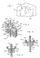
- FIGURE 2 is an enlarged fragmented sectional view illustrating a feedthrough filter capacitor assembly embodying the novel features of the invention;
- FIGURE 3 is a fragmented vertical sectional view of a terminal pin subassembly for use in the invention;
- FIGURE 4 is a fragmented sectional view similar to FIG. 3, and illustrating mounting of the terminal pin subassembly onto the conductive housing of a heart pacemaker or the like;
- FIGURE 5 is a fragmented and inverted vertical sectional view similar to FIG. 4, and illustrating mounting of a filter capacitor in a position over the terminal pin subassembly, at one side of the heart pacemaker housing;
- FIGURE 6 is a fragmented vertical sectional view similar to FIG. 5, and showing conductive attachment of the filter capacitor to a terminal pin and to the pacemaker housing;
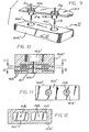
- FIGURE 7 is an exploded perspective view illustrating one alternative preferred form for the filter capacitor for use in the invention;
- FIGURE 8 is an enlarged vertical sectional view illustrating the filter capacitor of FIG. 7, in assembled form;
- FIGURE 9 is a fragmented exploded perspective view illustrating another alternative preferred form of the invention;
- FIGURE 10 is an enlarged vertical sectional view taken generally on the line 10-10 of FIG. 9;
- FIGURE 11 is an enlarged horizontal sectional view taken generally on the line 11-11 of FIG. 10;
- FIGURE 12 is an enlarged horizontal sectional view taken generally on the line 12-12 of FIG. 10;
- FIGURE 13 is an exploded and fragmented perspective view showing another alternative preferred form of the invention;
- FIGURE 14 is an enlarged vertical sectional view taken generally on the line 14-14 of FIG. 13;
- FIGURE 15 is a horizontal sectional view taken generally on the line 15-15 of FIG. 14;
- FIGURE 16 is a horizontal sectional view taken generally on the line 16-16 of FIG. 14;
- FIGURE 17 is an exploded and fragmented perspective view depicting a further alternative preferred embodiment of the invention;
- FIGURE 18 is another exploded and fragmented perspective view of an alternative preferred form of the invention;
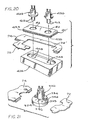
- FIGURE 19 is an exploded and fragmented perspective view of still another alternative preferred embodiment of the invention;
- FIGURE 20 is an exploded perspective view similar to FIG. 19, and illustrating a modified form of the invention; and
- FIGURE 21 is a fragmented exploded perspective view showing a still further alternative form of the invention.
-
- As shown in the exemplary drawings, a feedthrough capacitor assembly referred to generally in FIGURE 2 by the
reference numeral 10 is provided for suppressing or filtering and shielding undesired electrical interference signals from a conductive terminal pin or lead 12. As shown in FIGURE 1, thefeedthrough assembly 10 is particularly adapted for use in an implantable medical device such as a heart pacemaker ordefibrillator 14 or the like for supplying electrical signals via alead 16 to theheart 18 of apatient 20. Thefeedthrough assembly 10 is designed for simplified installation onto a conductive housing 22 (FIG. 2) of themedical device 14 to provide a hermetically sealed electrical connection to theconductive lead 16 through thehousing 22 for appropriate connection to electronic components (not shown) within the medical device, while attenuating and shielding unwanted interference signals along thelead 12 and thereby preventing significant transmission of said signals into the interior of the housing. - In general terms, as viewed in FIGS. 2 and 5, the feedthrough
filter capacitor assembly 10 of the present invention includes afeedthrough filter capacitor 24 in combination with aterminal pin subassembly 26 which can be constructed separately from the capacitor as a prefabricated unit, or otherwise obtained as an available commercial product. Thefilter capacitor 24 andterminal pin subassembly 26 are desirably mounted separately onto thepacemaker housing 22, with thecapacitor 24 generally surrounding and preferably overlying theterminal pin subassembly 26. In some embodiments, the capacitor may be mounted directly to the terminal pin subassembly, before or after attachment thereof to thehousing 22. With these configurations, as will be described in more detail, the components of thefeedthrough assembly 10 can be constructed and installed in a cost-efficient and reliable manner, while providing theterminal pin 12 with effective attenuation and shielding against passage of unwanted noise signals. - The
terminal pin subassembly 26 is shown best in FIGS. 3 and 4 to include theconductive lead 12 formed typically from a selected and biocompatible metal, such as platinum, tantalum or niobium wire or the like. The conductive lead orpin 12 is provided, as is known in the art, for passage of electrical signals through thehousing 22, with one or more suchconductive pins 12 being required in a typical pacemaker or defibrillator applicator in accordance with the number of leads 16. Theconductive pin 12 is adapted for electrical connection (not shown) to the associatedlead 16, and further to electronic control circuitry (also not shown) within the pacemaker housing of the medical device, as known to persons skilled in the art. - As shown in FIG. 3, the
terminal pin 12 is supported within an outercylindrical ferrule 28 formed from a suitable conductive material, such as titanium or titanium alloy. Theterminal pin 12 is supported within theferrule 28 in spaced nonconductive relation, by means of an insulative mounting ring orbead 30. Thisinsulator ring 30 provides a hermetic seal to prevent passage of body fluids through theterminal pin subassembly 26, when said subassembly is mounted onto thepacemaker housing 22. Glass-fired or ceramic-based materials such as polycrystaline alumina, sapphire crystal or the like are commonly used to form theinsulator ring 30. Examples of prefabricated terminal pin subassemblies of this general type are shown and described in more detail in U.S. Patents 3,920,888 and 4,421,947 which are incorporated by reference herein. - As shown in FIG. 4, in accordance with the apparatus and method of the present invention, the prefabricated
terminal pin subassembly 26 is adapted for quick and easy mounting onto thehousing 22, within a preformedopening 32 formed therein. In this regard, the preferred ferrule shape includes an outboard end segment 28' of expanded diametric size to define a radially outwardly projectingshoulder 34 sized to seat against an outboard surface of thehousing 22, with the smaller diameter inboard end of theferrule 28 projecting axially through theopening 32 to the interior of the pacemaker housing. Theferrule 28 is securely connected to theconductive housing 22, formed typically from titanium or titanium alloy, by means of a welded or brazedconnection 38. Importantly, thisconnection 38 forms a high quality electrical connection between theferrule 28 and thehousing 22, while additionally providing a hermetic seal therebetween. Theterminal pin 12 is thus supported on thehousing 22, in hermetically sealed and electrically insulated relation, for passage through thehousing opening 32. - The
filter capacitor 24 comprises, in the form shown in FIGS. 2, 5 and 6, a discoidal capacitor having first and second sets ofelectrode plates dielectric base structure 44 of ceramic monolith construction or the like. Although the exemplary drawings show in exaggerated scale a pair ofconductive plates 40 in parallel staggered relation with a corresponding pair of theconductive plates 42, it will be understood that a large plurality of typically 5-40conductive plates 40 will be provided in alternatingly stacked and parallel spaced relation with a corresponding number of theplates 42. One side of the illustrative discoidal capacitor defines acounterbore 46 having a sufficient radial size and axial depth to permit placement of thecapacitor 24 in seated relation against the inboard surface of thehousing 22, with the inboard-extending portion of theferrule 28 received within thecapacitor counterbore 46. In this configuration, theterminal pin 12 projects through acentral opening 48 in thecapacitor 24, wherein thiscentral opening 48 is coaxially aligned with thecounterbore 46. - The set of
inner electrode plates 40 include marginal edges communicating with the inner diameter surface of thediscoidal capacitor 24, at thecentral opening 48. As known in the art, this central opening is normally lined with a metallized or silverized or plated metallic film for electrically connecting theplates 40 to each other. Similarly, the second or outer set of theelectrode plates 42 include outer margins disposed at the periphery of thecapacitor base structure 44, wherein theseouter plates 42 are electrically connected to each other by an appropriate metallized or silverized or plated metallic film. These metallized films at the inner and outer surfaces of thecapacitor 24 are identified in FIGS. 5 and 6 by thereference numerals - FIGS. 5 and 6 depict a preferred method of constructing the
feedthrough capacitor assembly 10, wherein thefilter capacitor 24 is placed over the invertedterminal pin subassembly 26. An optional disk-shaped epoxy preform 53 (FIG. 5) can be positioned about theterminal pin 12 at a location sandwiched between the inboard-extending end of theferrule 28 and the bottom of thecapacitor counterbore 46. In this position, theepoxy preform 53 supports thecapacitor 24 in slight spaced relation above the inboard face of thehousing 22. The partially assembled structure as described is placed in an oven and subjected to heat represented byarrows 51 in an amount sufficient to cause theepoxy preform 53 to melt and flow. As the melting of the preform occurs, a portion of the epoxy is drawn into the adjacent end of thecapacitor opening 48 to close and seal that opening at the counterbore 46 (FIG. 6). Additional epoxy flows down around theferrule 28, concurrently with downward movement of thecapacitor 24 to a position seated flush on thehousing 22. Sufficient epoxy flows to the juncture of thehousing 22 and the counterbore periphery to secure or fixture the capacitor onto thehousing 22, when the epoxy cures to a rigid state. - The metallized
surface 50 within thecentral capacitor opening 48 is then connected electrically to theterminal pin 12 by means of a conductiveadhesive bead 54, or by soldering or brazing or the like. In the preferred form, theconductive adhesive 54 is applied to the annular gap between thepin 12 and thecapacitor surface 50, and allowed to fill a portion (about one-half) of the gap length. Similarly, the metallizedsurface 52 associated with theouter electrode plates 42 of the capacitor is connected electrically to the inboard surface of thepacemaker housing 22 by means of anadditional fillet 56 of conductive adhesive or the like. One preferred conductive adhesive comprises a curable polyimide adhesive loaded with conductive particles such as spheres or flakes, as described by way of example in U.S. Patent 4,424,551, which is incorporated by reference herein. However, it will be understood that other conductive connecting means may be used, such as solder, braze or the like. Importantly, theadhesive beads capacitor 24 in a secured stable manner to thehousing 22. - In use, the thus-installed
capacitor 24 effectively decouples and shields unwanted noise signals from theconductive lead 12, by capacitively connecting those signals to thehousing 22. That is, thehousing 22 cooperates with thecapacitor 24 and the terminal 26 to form an integral shield which reflects and absorbs the undesired radiated noise signals and thereby prevents entry of those signals into the interior of the housing. Installation of thecapacitor 24 in association with theterminal pin subassembly 26, in overlying and surrounding relation therewith, is significantly easier than conventional capacitor installation into the small annular gap formed radially between theconductive pin 12 andferrule 28 of the terminal pin subassembly. In addition, the diametric size of the capacitor is not restricted to the size of the small annular gap, whereby a filter capacitor of significantly increased capacitance for improved filter efficiency can be used. Moreover, mounting of thecapacitor 24 subsequent to welded or brazed connection of theterminal pin subassembly 26 to thehousing 22 avoids exposure of the ceramic capacitor structure to high welding temperatures. - One alternative preferred form of a feedthrough discoidal filter capacitor for' use in the present invention is shown in FIGS. 7 and 8, wherein a modified
filter capacitor 24' is formed by assembly of a primary base structure 44' with a mountingring 60. More specifically, the capacitor base structure 44' comprises a conventional discoidal capacitor having the sets ofconductive plates central opening 48. The mountingring 60 is formed from a structure which corresponds to or is otherwise compatible with the capacitor base structure 44', to include a conforming outer peripheral shape in combination with acentral opening 62 which is much larger than theopening 48. These two components 44' and 60' are connected together in coaxial relation by suitable bonding as viewed in FIG. 7. These components can be formed from similar ceramic material and bonded together in the unfired or green state followed by co-firing to form a single monolith structure. Alternately, the components can be individually fired and thereafter bonded by glass frit at approximately 600°C, nonconductive polyimide at about 270°C, or epoxies at about 150°C. Thecentral opening 48 and the peripheries of bothcomponents 44', 60 are then metallized with the film surfaces 50 and 52, as previously described. The assembled components cooperatively define thecounterbore 46 for receiving theferrule 28 of a terminal pin subassembly, as previously described. A radially open vent or notch 64 may be formed in the mountingring 60 to accommodate vented passage of outgas constituents in the course of curing conductive adhesive materials. The metallizedsurface 52 is continued on the exterior of the mountingring 60 for electrical connection to thehousing 22, all in accordance with the method of assembly as previously described. - FIGS. 9-12 illustrate another alternative preferred form of the invention, wherein a further modified
capacitor base structure 44" includes a plurality of feedthrough filter capacitors disposed in a unitized and substantially planar array with each filter capacitor defined by sets of embedded electrode plates 40' and 42'. In this configuration, each filter capacitor is associated with a corresponding counterbore 46' for mounting over theferrule 28 of a correspondingterminal pin subassembly 26. Themulticapacitor base structure 44" can be constructed as a monolithic base in the manner described with respect to FIGS. 2, 5 and 6, or in the form of assembled base components as described with respect to FIGS. 7 and 8. Moreover, as viewed in FIG. 11, the outer ground electrode plates 42' for the multiple filter capacitors may be common plates. In amedical device 14 having multipleconductive leads 12, thesingle capacitor structure 44" having the multiple coplanar filter capacitors therein may be installed onto the inboard side of thehousing 22 in a single step, by installing the monolithic capacitor base structure over several terminal pin subassemblies 26 (FIG. 9). Once again, the outer grounding electrodes 42' can be connected to thehousing 22 by means of conductive adhesive or the like, with theterminal pin 12 of eachterminal pin subassembly 26 also connected quickly and easily to the associated capacitor by means of conductive adhesive. - FIGURES 13-16 show another alternative form of the invention, wherein a modified feedthrough
filter capacitor assembly 100 is formed by a combination of afeedthrough filter capacitor 124 with a conventional and commercially available multiconductorterminal pin subassembly 126. The illustrative terminal pin subassembly has four parallel terminal pins 112 supported in insulative relation within a typically glass-based or ceramic basedinsulator ring 130 mounted in turn within a cylindricalconductive ferrule 128. Theferrule 128 includes a radially outwardly projectingflange 134 for secure attachment in a hermetically sealed manner, as by welding or brazing, to aconductive housing 22 of an implanted medical device or the like. Theferrule flange 134 supports theferrule 128 with quad-mounted terminal pins 112 extending through anopening 32 in the housing. - Subsequent to mounting of the
terminal pin subassembly 126, as described, thecapacitor 124 is mounted onto the inboard side or face of thehousing 22. Theillustrative capacitor 124 includes acounterbore 146 in one side thereof to accommodate the inboard-projecting portions of theterminal pin subassembly 126. A series of fouropenings 148 are formed in thecapacitor 124 for through passage of the fourterminal pins 112. As shown in FIGS. 14-16, the capacitor openings ' 148 are individually associated with pie-shaped innerconductive electrode plates 140 stacked in alternate array with commonly formedground electrode plates 142. The inner plates are electrically connected at the associatedopening 148, by a metallizedsurface film 150, and the ground plates are electrically connected at the capacitor periphery to a metallized surface film 152. Thecapacitor 124 is mounted onto thehousing 22, in respective electrical connection with thehousing 22 and the multipleterminal pins 112 in the same manner as described previously with respect to FIGS. 1 through 12. - Another alternative embodiment is shown in FIG. 17, wherein a flush-mounted
feedthrough filter capacitor 224 is provided for installation at the inboard face of aconductive housing 22 or the like in operative association with aterminal pin subassembly 226. In this configuration, the terminal pin subassembly includes aferrule 228 mounted by anouter flange 234 to thehousing 22, with aninsulator ring 230 contained within the ferrule and supporting a pair of feedthrough terminal pins 212. Theferrule 228 andinsulator ring 230 are designed to define a flush surface which does not protrude beyond the inboard face of thehousing 22 into the housing interior. Thecapacitor 224, shown with a pair ofopenings 248 for through passage of theterminal pins 212 may thus omit the counterbore described with respect to other embodiments of the invention. Importantly, however, thecapacitor 224 is mounted in operative association with theterminal pins 212 in the same manner as previously described, subsequent to mounting of the terminal pin subassembly onto thehousing 22. Appropriate sets of conductive plates are contained within thecapacitor 224 to provide the desired signal filtering and shielding function. - FIGURE 18 depicts another modified assembly adapted for convenient installation along a seam 70 defined upon assemblage of
conductive shells housing 22 of the pacemaker or the like. In this version of the invention, aterminal pin subassembly 362 includes a modifiedferrule 328 having theinsulator ring 330 and associated terminal pin or pins 312 supported therein. The modifiedferrule 328 is adapted for assembly with a feedthrough filter capacitor 324, which may correspond with thecapacitor 224 of FIG. 17 modified to include acounterbore 346 surrounding theterminal pin openings 348. - The
ferrule 328 of FIG. 18 includes outboard andinboard flanges housing shells ferrule 328 is preassembled first to one of thehousing shells inboard flange 335. In this regard, the inboard flange has a sufficient radial size for capacitor mounting thereto in the same manner as previously described with respect to mounting of the feedthrough capacitor directly to the housing. The other housing shell is then fitted with the ferrule to close thehousing 22, and a hermetic seal can be formed as by welding the periphery of theoutboard flange 334 to the housing. The seam 70 is also closed in the same manner to provide a hermetic seal. - FIGURE 19 shows another multicapacitor embodiment wherein an elongated micro-planar
array feedthrough capacitor 424 including internal conductive plate sets (not shown) is adapted for mounting onto the inboard side of apacemaker housing 22 or the like. Thecapacitor 424 is shown with two pairs of throughopenings 448 disposed to receiveterminal pins 412 of a pair of bipolarterminal pin subassemblies 426. Eachterminal pin subassembly 426 includes an insulator ring 430 to support the - associated pair of terminal pins within a conductiveouter ferrule 428 shown with a shape generally corresponding with theferrule 128 of FIG. 13. Theferrules 428 are adapted for mounting as by welding or brazing onto asubplate 80 of conductivemetal having openings 82 therein. Thecapacitor 424 is then mounted onto the inboard side of thesubplate 80, in operative relation with the terminal pins 412, in the same manner as previously described. Thesubplate 80 is thereafter mounted over an elongated opening 32' in thehousing 22 by welding or soldering. Aselongated counterbore 446 is formed as by machining into one side of the capacitor base to accommodate inboard - extending portions of the terminal pin assemblies. In this embodiment, a rectangular feedthrough capacitor structure is shown in relation to the pair of terminal pin subassemblies of circular cross-sectional shape. - A modified multicapacitor embodiment is shown in FIG. 20, wherein structural components corresponding with those depicted in FIG. 19 are identified by the same reference numerals. As shown, a pair of bipolar
terminal pin subassemblies 426 havingterminal pins 412 are mounted onto a modified subplate 80', to extend throughopenings 82 in the subplate. The modified subplate 80' includes upper and lower, outwardly radiatingflanges interfitting housing shells terminal pin subassemblies 426 thereon, is assembled first to one of thehousing shells multiconductor capacitor 424 onto theinboard flange 435, and follow-on assembly of the other housing shell within subplate groove. Alternately, thecapacitor 424 can be assembled to the inboard flange of the subplate 80' with terminal pin subassemblies pre-installed thereon, followed by installation of the housing shells with the subplate groove. - Mounting of a feedthrough capacitor onto a terminal pin subassembly prior to installation onto the housing is shown in more detail in FIG. 21, wherein a bipolar
terminal pin subassembly 326 and associated feedthrough capacitor 324 are provided of the type depicted previously in FIG. 18. In this version, the pre-constructedterminal pin subassembly 326 is mounted on the feedthrough capacitor 324, preferably by means of anannular bead 356 of conductive adhesive or the like applied to the capacitor at the periphery of theinboard ferrule flange 335. This resultant feedthrough assembly is then installed onto one of the associatedhousing shells ferrule flanges - The improved feedthrough capacitor assembly of the present invention may thus be implemented in a variety of specific configurations to provide a simplified and economical assembly of a feedthrough filter capacitor with a prefabricated terminal pin subassembly. In view of the embodiments as shown and described, it will be understood that features of the disclosed forms may be interchanged to provide a terminal pin subassembly of any desired configuration adapted for mounting onto a device housing or the like, in combination with a feedthrough capacitor installed in operative relation with one or more terminal pins. In such embodiments, abrasive or microblast surface preparation of titanium materials may be desirable to remove surface oxides preparatory to the steps of welding, brazing, or application of conductive adhesives, etc., in order to obtain optimum electrical and hermetically sealed connections. In use, the feedthrough filter capacitor both suppresses and shields against undesired interference signals to prevent passage of those interference signals along the
conductive lead pin 12, particularly in a heart pacemaker application or the like. - A variety of further modifications and improvements to the feedthrough filter capacitor assembly of the present invention will be apparent to those persons skilled in the art. Accordingly, no limitation on the invention is intended by way of the foregoing description and accompanying drawings, except as set forth in the appended claims.
Claims (17)
- A feedthrough filter capacitor assembly (10, 100), comprising:characterized in that the feedthrough filter capacitor (24, 24', 124, 224, 324, or 424) is mounted outside the ferrule (28, 128, 228, 328 or 428) in the axial direction.a terminal pin subassembly (26, 126, 226, 362, or 426), including at least one conductive terminal pin (12, 112, 212, 312, or 412), a cylindrical conductive ferrule (28, 128, 228, 328, or 428), and insulator means (30, 130, 230, 330, or 430) for mounting said terminal pin (12, 112, 212, 312, or 412) to extend through said ferrule (28, 128, 228, 328, or 428) in hermetically sealed, electrically insulated relation therewith, mounted in an opening (32, or 32') formed in a conductive substrate (22); anda feedthrough filter capacitor (24, 24', 124, 224, 324, or 424) having a central opening (48, 148, 248, 348, or 448) formed therein for pass-through reception of said terminal pin (12, 112, 212, 312, or 412), said capacitor (24, 24', 124, 224, 324, or 424) having first (40, 40' or 140) and second (42, 42', or 142) sets of electrode plates adapted for electrical connection respectively to said terminal pin (12, 112, 212, 312, or 412) and substrate (22);
- The feedthrough filter capacitor assembly (10, 100) of claim 1, wherein said filter capacitor (24, 24', 124, 224, 324, or 424) comprises a discoidal capacitor (24, 24').
- The feedthrough filter capacitor assembly (10, 100) of claim 2, wherein said discoidal capacitor (24, 24') has a radially open vent (64) formed therein.
- The feedthrough filter capacitor assembly (10, 100) of claim 1, wherein said feedthrough filter capacitor (24, 24', 124, 224, 324, or 424) is mounted onto the substrate (22).
- The feedthrough filter capacitor assembly (10, 100) of claim 1, wherein said capacitor (24, 24', 124, 224, 324, or 424) has a recess (46, 46', 146, 246, 346, or 446) formed at one side thereof for receiving at least a portion of said terminal pin subassembly whereby said capacitor (24, 24', 124, 224, 324, or 424) circumferentially surrounds at least a portion of said terminal pin subassembly (28, 128, 228, 328, or 428).
- The feedthrough filter capacitor assembly (10, 100) of claim 1, further including first means for electrically connecting (50, 150) said first set of electrode plates (40, 40', or 140) to said terminal pin (12, 112, 212, 312, or 412), and second means for electrically connecting (52, 152) said second set of electrode plates (42, 42', or 142) to the substrate (22).
- The feedthrough filter capacitor assembly (10,100) of claim 6, wherein said first means (50, 150) and said second means (52, 152) comprise a conductive adhesive (54).
- The feedthrough filter capacitor assembly (10,100) of claim 5, wherein said filter capacitor (24, 24', 124, 224, 324, or 424) comprises a base structure (44, 44', or 44") having said first (40, 40', or 140) and second (42, 42', or 142) sets of electrode plates embedded therein and further having said central opening (48, 148, 248, 348, or 448) formed therein, and a mounting ring (30, 130, 230, 330, or 430) mounted on said base structure (44, 44', or 44") at one side thereof, said base structure (44, 44', or 44") and said mounting ring (30, 130, 230, 330, or 430) cooperatively defining said recess (46, 46', 146, 246, 346, or 446).
- The feedthrough filter capacitor assembly (10,100) of claim 4, wherein said substrate (22) comprises a subplate (80,80') adapted for mounting onto a housing (22) of the medical device (14).
- The feedthrough filter capacitor assembly (10,100) of claim 1, wherein said feedthrough filter capacitor (24, 24', 124, 224, 324, or 424) includes a dielectric base (44) having at least one central opening (48, 148, 248, 348, or 448) formed therein.
- The feedthrough filter capacitor assembly (10,100) of claim 4, including means for mounting (53, 54, or 56) said filter capacitor (24, 24', 124, 224, 324, or 424) at one side of said substrate (22) and axially at one outer side of said terminal pin mounting means (28, 128, 228, 328, or 428).
- The feedthrough filter capacitor assembly (10,100) of claim 11, wherein said filter capacitor mounting means (54, or 56) comprises a conductive adhesive.
- The feedthrough filter capacitor assembly (10,100) of claim 6, wherein said first set of electrode plates (40, 40', or 140) each have a marginal edge exposed within said central opening (48, 148, 248, 348, or 448), and said second set of electrode plates (42, 42', 142) each have a marginal edge exposed at a selected outer surface of said dielectric base (44) at a position remote from said central opening (48, 148, 248, 348, or 448).
- A method of mounting a feedthrough filter capacitor (24, 24', 124, 224, 324, or 424) to a conductive substrate (22), for use in an implantable medical device (14), said method comprising the steps of:forming a terminal pin subassembly (26, 126, 226, 362, or 426), including at least one conductive terminal pin (12, 112, 212, 312, or 412), a cylindrical conductive ferrule (28, 128, 228, 328, or 428), and insulator means (30, 130, 230, 330, or 430) for mounting said terminal pin (12, 112, 212, 312, or 412) to extend through said ferrule (28, 128, 228, 328, or 428) in hermetically sealed, electrically insulated relation therewith;mounting the terminal pin subassembly (26, 126, 226, 362, or 426) onto a conductive substrate (22) with the terminal pin (12, 112, 212, 312, or 412) extending through a substrate opening (32, 32') and with said ferrule (28, 128, 228, 328, or 428) projecting generally coaxially with said substrate opening (32, 32');forming a feedthrough filter capacitor (24, 24', 124, 224, 324, or 424) including a dielectric base (44) having at least one central opening (48, 148, 248, 348, or 448) formed therein, said dielectric base (44) having embedded therein a first set of electrode plates (40, 40', or 140) each having a marginal edge exposed within said central opening (48, 148, 248, 348, or 448), and a second set of electrode plates (42, 42', 142) each having a marginal edge exposed at a selected outer surface of said base (44) at a position remote from said central opening (48, 148, 248, 348, or 448); andmounting said filter capacitor (24, 24', 124, 224, 324, or 424) onto a selected one of said substrate (22) and said ferrule (28, 128, 228, 328, or 428) at one side of said substrate (22) so as to be outside the ferrule in the axial direction with said first (40, 40', or 140) and second (42, 42', 142) sets of electrode plates electrically connected respectively to said terminal pin (12, 112, 212, 312, or 412) and said substrate (22).
- The method of claim 14, wherein the step of forming a terminal pin subassembly (26, 126, 226, 362, or 426) includes forming a plurality of terminal pin subassemblies (26, 126, 226, 362, or 426) and a plurality of feedthrough filter capacitor (24, 24', 124, 224, 324, or 424).
- The method of claim 15, wherein the plurality of feedthrough filter capacitors (24, 24', 124, 224, 324, or 424) includes a base of each said capacitors (24, 24', 124, 224, 324, or 424) comprising a unitary base structure (44, 44', 44") and the step of mounting the filter capacitors (24, 24', 124, 224, 324, or 424) includes mounting said unitary base structure (44, 44', 44") onto the selected one of said substrate (22) and said ferrule (28, 128, 228, 328, or 428).
- The method of claim 14, wherein the step of mounting said filter capacitor (24, 24', 124, 224, 324, or 424) includes mounting said capacitor (24, 24', 124, 224, 324, or 424) axially at one outer side of said ferrule (28, 128, 228, 328, or 428) with said first (40, 40', or 140) and second (42, 42', 142) sets of electrode plates electrically connected respectively to said terminal pin (12, 112, 212, 312, or 412) and said ferrule (28, 128, 228, 328, or 428), and thereafter mounting the terminal pin subassembly (26, 126, 226, 362, or 426) onto the conductive substrate (22) with the terminal pin (12, 112, 212, 312, or 412) extending through a substrate opening (32, 32') and with said ferrule (28, 128, 228, 328, or 428) projecting generally coaxially with said substrate opening (32, 32').
Applications Claiming Priority (2)
| Application Number | Priority Date | Filing Date | Title |
|---|---|---|---|
| US55981 | 1993-05-03 | ||
| US08/055,981 US5333095A (en) | 1993-05-03 | 1993-05-03 | Feedthrough filter capacitor assembly for human implant |
Publications (3)
| Publication Number | Publication Date |
|---|---|
| EP0623363A2 EP0623363A2 (en) | 1994-11-09 |
| EP0623363A3 EP0623363A3 (en) | 1997-05-28 |
| EP0623363B1 true EP0623363B1 (en) | 2002-09-11 |
Family
ID=22001370
Family Applications (1)
| Application Number | Title | Priority Date | Filing Date |
|---|---|---|---|
| EP94106246A Expired - Lifetime EP0623363B1 (en) | 1993-05-03 | 1994-04-21 | Feed-through filter capacitor assembly for human implant |
Country Status (3)
| Country | Link |
|---|---|
| US (1) | US5333095A (en) |
| EP (1) | EP0623363B1 (en) |
| DE (1) | DE69431324T2 (en) |
Cited By (7)
| Publication number | Priority date | Publication date | Assignee | Title |
|---|---|---|---|---|
| US7675729B2 (en) | 2003-12-22 | 2010-03-09 | X2Y Attenuators, Llc | Internally shielded energy conditioner |
| US7688565B2 (en) | 1997-04-08 | 2010-03-30 | X2Y Attenuators, Llc | Arrangements for energy conditioning |
| US7733621B2 (en) | 1997-04-08 | 2010-06-08 | X2Y Attenuators, Llc | Energy conditioning circuit arrangement for integrated circuit |
| US7768763B2 (en) | 1997-04-08 | 2010-08-03 | X2Y Attenuators, Llc | Arrangement for energy conditioning |
| US7782587B2 (en) | 2005-03-01 | 2010-08-24 | X2Y Attenuators, Llc | Internally overlapped conditioners |
| US7817397B2 (en) | 2005-03-01 | 2010-10-19 | X2Y Attenuators, Llc | Energy conditioner with tied through electrodes |
| US9054094B2 (en) | 1997-04-08 | 2015-06-09 | X2Y Attenuators, Llc | Energy conditioning circuit arrangement for integrated circuit |
Families Citing this family (267)
| Publication number | Priority date | Publication date | Assignee | Title |
|---|---|---|---|---|
| US5406444A (en) * | 1993-03-29 | 1995-04-11 | Medtronic, Inc. | Coated tantalum feedthrough pin |
| AU3299995A (en) * | 1994-10-04 | 1996-04-18 | Medtronic, Inc. | Protective feedthrough |
| US5817984A (en) * | 1995-07-28 | 1998-10-06 | Medtronic Inc | Implantable medical device wtih multi-pin feedthrough |
| WO1997012645A1 (en) * | 1995-10-03 | 1997-04-10 | Intermedics, Inc. | Feedthrough assembly with transient voltage suppressor and emi filter for implantable medical devices |
| US5650759A (en) * | 1995-11-09 | 1997-07-22 | Hittman Materials & Medical Components, Inc. | Filtered feedthrough assembly having a mounted chip capacitor for medical implantable devices and method of manufacture therefor |
| US5751539A (en) * | 1996-04-30 | 1998-05-12 | Maxwell Laboratories, Inc. | EMI filter for human implantable heart defibrillators and pacemakers |
| US5978204A (en) * | 1995-11-27 | 1999-11-02 | Maxwell Energy Products, Inc. | Capacitor with dual element electrode plates |
| DE69631735T2 (en) * | 1995-11-27 | 2005-01-20 | Greatbatch-Sierra, Inc., Carson City | Assembly of feedthrough capacitors |
| JP2688347B2 (en) * | 1996-04-09 | 1997-12-10 | 宇呂電子工業株式会社 | Leakage radiation prevention element |
| US5817130A (en) * | 1996-05-03 | 1998-10-06 | Sulzer Intermedics Inc. | Implantable cardiac cardioverter/defibrillator with EMI suppression filter with independent ground connection |
| US5777276A (en) * | 1996-07-26 | 1998-07-07 | Micronics Computers Inc. | Mother board with auxiliary conductors in parallel with power connectors |
| US5825608A (en) * | 1996-10-18 | 1998-10-20 | Novacap, Inc. | Feed-through filter capacitor assembly |
| US6055455A (en) | 1997-01-06 | 2000-04-25 | Cardiac Pacemakers, Inc. | Filtered feedthrough for an implantable medical device |
| US6018448A (en) * | 1997-04-08 | 2000-01-25 | X2Y Attenuators, L.L.C. | Paired multi-layered dielectric independent passive component architecture resulting in differential and common mode filtering with surge protection in one integrated package |
| US5895293A (en) * | 1997-04-23 | 1999-04-20 | The Whitaker Corporation | Filtered terminal block assembly |
| US5870272A (en) * | 1997-05-06 | 1999-02-09 | Medtronic Inc. | Capacitive filter feedthrough for implantable medical device |
| US5905627A (en) * | 1997-09-10 | 1999-05-18 | Maxwell Energy Products, Inc. | Internally grounded feedthrough filter capacitor |
| US6275369B1 (en) | 1997-11-13 | 2001-08-14 | Robert A. Stevenson | EMI filter feedthough terminal assembly having a capture flange to facilitate automated assembly |
| US6643903B2 (en) * | 1997-11-13 | 2003-11-11 | Greatbatch-Sierra, Inc. | Process for manufacturing an EMI filter feedthrough terminal assembly |
| US6008980A (en) * | 1997-11-13 | 1999-12-28 | Maxwell Energy Products, Inc. | Hermetically sealed EMI feedthrough filter capacitor for human implant and other applications |
| US5959829A (en) * | 1998-02-18 | 1999-09-28 | Maxwell Energy Products, Inc. | Chip capacitor electromagnetic interference filter |
| US5973906A (en) * | 1998-03-17 | 1999-10-26 | Maxwell Energy Products, Inc. | Chip capacitors and chip capacitor electromagnetic interference filters |
| AU3219899A (en) * | 1998-03-31 | 1999-10-18 | Knowles Electronics, Inc. | Microphone with reduced rf sensitivity |
| US5999398A (en) * | 1998-06-24 | 1999-12-07 | Avx Corporation | Feed-through filter assembly having varistor and capacitor structure |
| US6141588A (en) * | 1998-07-24 | 2000-10-31 | Intermedics Inc. | Cardiac simulation system having multiple stimulators for anti-arrhythmia therapy |
| DE19835843C2 (en) * | 1998-08-07 | 2000-06-29 | Epcos Ag | Solderless, coaxial feedthrough component |
| US6424234B1 (en) | 1998-09-18 | 2002-07-23 | Greatbatch-Sierra, Inc. | Electromagnetic interference (emi) filter and process for providing electromagnetic compatibility of an electronic device while in the presence of an electromagnetic emitter operating at the same frequency |
| US9061139B2 (en) * | 1998-11-04 | 2015-06-23 | Greatbatch Ltd. | Implantable lead with a band stop filter having a capacitor in parallel with an inductor embedded in a dielectric body |
| US6701176B1 (en) | 1998-11-04 | 2004-03-02 | Johns Hopkins University School Of Medicine | Magnetic-resonance-guided imaging, electrophysiology, and ablation |
| US8244370B2 (en) | 2001-04-13 | 2012-08-14 | Greatbatch Ltd. | Band stop filter employing a capacitor and an inductor tank circuit to enhance MRI compatibility of active medical devices |
| US6159560A (en) * | 1998-11-25 | 2000-12-12 | Stevenson; Robert A. | Process for depositing a metal coating on a metallic component of an electrical structure |
| AU1198700A (en) | 1999-03-16 | 2000-10-04 | Maxwell Energy Products | Low inductance four terminal capacitor lead frame |
| DE19957189A1 (en) | 1999-11-20 | 2001-05-23 | Biotronik Mess & Therapieg | Multipolar electric filter insert for implantable electronic therapy device, e.g. heart pacemaker or defibrillator; has insert body and filter block connected to freely project into pacemaker casing |
| US6349025B1 (en) * | 1999-11-30 | 2002-02-19 | Medtronic, Inc. | Leak testable capacitive filtered feedthrough for an implantable medical device |
| EP1109180B1 (en) | 1999-12-14 | 2012-02-08 | Greatbatch Ltd. | Emi Filter feedthrough terminal assembly |
| US6414835B1 (en) | 2000-03-01 | 2002-07-02 | Medtronic, Inc. | Capacitive filtered feedthrough array for an implantable medical device |
| US6459935B1 (en) | 2000-07-13 | 2002-10-01 | Avx Corporation | Integrated filter feed-thru |
| US6529103B1 (en) | 2000-09-07 | 2003-03-04 | Greatbatch-Sierra, Inc. | Internally grounded feedthrough filter capacitor with improved ground plane design for human implant and other applications |
| US6882248B2 (en) | 2000-09-07 | 2005-04-19 | Greatbatch-Sierra, Inc. | EMI filtered connectors using internally grounded feedthrough capacitors |
| US6699265B1 (en) * | 2000-11-03 | 2004-03-02 | Cardiac Pacemakers, Inc. | Flat capacitor for an implantable medical device |
| US6833987B1 (en) * | 2000-11-03 | 2004-12-21 | Cardiac Pacemakers, Inc. | Flat capacitor having an active case |
| US7456077B2 (en) * | 2000-11-03 | 2008-11-25 | Cardiac Pacemakers, Inc. | Method for interconnecting anodes and cathodes in a flat capacitor |
| FR2816443A1 (en) * | 2000-11-03 | 2002-05-10 | Saint Gobain Ceramiques Avance | METHOD FOR MANUFACTURING A SEALED BUSHING WITH INTEGRATED CAPACITOR AND ELEMENT THUS OBTAINED |
| US7355841B1 (en) * | 2000-11-03 | 2008-04-08 | Cardiac Pacemakers, Inc. | Configurations and methods for making capacitor connections |
| US7107099B1 (en) | 2000-11-03 | 2006-09-12 | Cardiac Pacemakers, Inc. | Capacitor having a feedthrough assembly with a coupling member |
| US6509588B1 (en) | 2000-11-03 | 2003-01-21 | Cardiac Pacemakers, Inc. | Method for interconnecting anodes and cathodes in a flat capacitor |
| US6687118B1 (en) * | 2000-11-03 | 2004-02-03 | Cardiac Pacemakers, Inc. | Flat capacitor having staked foils and edge-connected connection members |
| US6621012B2 (en) | 2001-02-01 | 2003-09-16 | International Business Machines Corporation | Insertion of electrical component within a via of a printed circuit board |
| US6433276B1 (en) * | 2001-03-14 | 2002-08-13 | John Bellora | Surface mount feedthrough |
| US7787958B2 (en) | 2001-04-13 | 2010-08-31 | Greatbatch Ltd. | RFID detection and identification system for implantable medical lead systems |
| US8457760B2 (en) | 2001-04-13 | 2013-06-04 | Greatbatch Ltd. | Switched diverter circuits for minimizing heating of an implanted lead and/or providing EMI protection in a high power electromagnetic field environment |
| US7899551B2 (en) * | 2001-04-13 | 2011-03-01 | Greatbatch Ltd. | Medical lead system utilizing electromagnetic bandstop filters |
| US8989870B2 (en) | 2001-04-13 | 2015-03-24 | Greatbatch Ltd. | Tuned energy balanced system for minimizing heating and/or to provide EMI protection of implanted leads in a high power electromagnetic field environment |
| US8977355B2 (en) | 2001-04-13 | 2015-03-10 | Greatbatch Ltd. | EMI filter employing a capacitor and an inductor tank circuit having optimum component values |
| US7916013B2 (en) * | 2005-03-21 | 2011-03-29 | Greatbatch Ltd. | RFID detection and identification system for implantable medical devices |
| US20070088416A1 (en) | 2001-04-13 | 2007-04-19 | Surgi-Vision, Inc. | Mri compatible medical leads |
| US9295828B2 (en) | 2001-04-13 | 2016-03-29 | Greatbatch Ltd. | Self-resonant inductor wound portion of an implantable lead for enhanced MRI compatibility of active implantable medical devices |
| US8219208B2 (en) | 2001-04-13 | 2012-07-10 | Greatbatch Ltd. | Frequency selective passive component networks for active implantable medical devices utilizing an energy dissipating surface |
| WO2002083016A1 (en) | 2001-04-13 | 2002-10-24 | Surgi-Vision, Inc. | Systems and methods for magnetic-resonance-guided interventional procedures |
| US8195295B2 (en) | 2008-03-20 | 2012-06-05 | Greatbatch Ltd. | Shielded three-terminal flat-through EMI/energy dissipating filter |
| US8712544B2 (en) | 2001-04-13 | 2014-04-29 | Greatbatch Ltd. | Electromagnetic shield for a passive electronic component in an active medical device implantable lead |
| US8509913B2 (en) | 2001-04-13 | 2013-08-13 | Greatbatch Ltd. | Switched diverter circuits for minimizing heating of an implanted lead and/or providing EMI protection in a high power electromagnetic field environment |
| US7853325B2 (en) * | 2001-04-13 | 2010-12-14 | Greatbatch Ltd. | Cylindrical bandstop filters for medical lead systems |
| US6622046B2 (en) * | 2001-05-07 | 2003-09-16 | Medtronic, Inc. | Subcutaneous sensing feedthrough/electrode assembly |
| US6545854B2 (en) | 2001-05-25 | 2003-04-08 | Presidio Components, Inc. | Fringe-field non-overlapping-electrodes discoidal feed-through ceramic filter capacitor with high breakdown voltage |
| US6619763B2 (en) | 2001-05-25 | 2003-09-16 | Presidio Components, Inc. | Feed-through filter capacitor with non-overlapping electrodes |
| US6760215B2 (en) * | 2001-05-25 | 2004-07-06 | Daniel F. Devoe | Capacitor with high voltage breakdown threshold |
| US7191008B2 (en) * | 2001-05-30 | 2007-03-13 | Medtronic, Inc. | Implantable medical device with a dual power source |
| US7337001B2 (en) * | 2001-05-30 | 2008-02-26 | Medtronic, Inc. | Implantable medical device and method with a dual power source incorporating electrolyte additive 2,2,2-trifluoroacetamide |
| US6650942B2 (en) | 2001-05-30 | 2003-11-18 | Medtronic, Inc. | Implantable medical device with dual cell power source |
| US6567259B2 (en) | 2001-05-31 | 2003-05-20 | Greatbatch-Sierra, Inc. | Monolithic ceramic capacitor with barium titinate dielectric curie point optimized for active implantable medical devices operating at 37° C. |
| US6456481B1 (en) | 2001-05-31 | 2002-09-24 | Greatbatch-Sierra, Inc. | Integrated EMI filter-DC blocking capacitor |
| US6512666B1 (en) | 2001-08-21 | 2003-01-28 | Delware Capital Formation, Inc. | High current filter feed-through capacitor |
| DE10206629A1 (en) * | 2002-02-15 | 2003-08-28 | Marconi Comm Gmbh | Hermetic microwave feedthrough |
| US6985347B2 (en) * | 2002-02-28 | 2006-01-10 | Greatbatch-Sierra, Inc. | EMI filter capacitors designed for direct body fluid exposure |
| US7917219B2 (en) | 2002-02-28 | 2011-03-29 | Greatbatch Ltd. | Passive electronic network components designed for direct body fluid exposure |
| US8660645B2 (en) * | 2002-02-28 | 2014-02-25 | Greatbatch Ltd. | Electronic network components utilizing biocompatible conductive adhesives for direct body fluid exposure |
| AU2003213646A1 (en) | 2002-02-28 | 2003-09-09 | Greatbatch-Sierra, Inc. | Emi feedthrough filter terminal assembly for human implant applications utilizing oxide resistant biostable conductive pads for reliable electrical attachments |
| US20030191505A1 (en) * | 2002-04-09 | 2003-10-09 | Mark Gryzwa | Magnetic structure for feedthrough filter assembly |
| US7211103B2 (en) * | 2002-04-11 | 2007-05-01 | Second Sight Medical Products, Inc. | Biocompatible bonding method and electronics package suitable for implantation |
| US6904307B2 (en) | 2002-05-29 | 2005-06-07 | Surgi-Vision, Inc. | Magnetic resonance probes |
| US6945331B2 (en) * | 2002-07-31 | 2005-09-20 | Schlumberger Technology Corporation | Multiple interventionless actuated downhole valve and method |
| AU2003264022A1 (en) * | 2002-08-07 | 2004-02-25 | Dearborn Electronics, Inc. | Improved electromagnetic interference filter |
| US6999818B2 (en) * | 2003-05-23 | 2006-02-14 | Greatbatch-Sierra, Inc. | Inductor capacitor EMI filter for human implant applications |
| US7623335B2 (en) * | 2003-02-27 | 2009-11-24 | Greatbatch-Sierra, Inc | Hermetic feedthrough terminal assembly with wire bond pads for human implant applications |
| US7038900B2 (en) * | 2003-02-27 | 2006-05-02 | Greatbatch-Sierra, Inc. | EMI filter terminal assembly with wire bond pads for human implant applications |
| US20040260354A1 (en) * | 2003-06-17 | 2004-12-23 | Nielsen Christian S. | Miniature compression feedthrough assembly for electrochemical devices |
| US7719854B2 (en) | 2003-07-31 | 2010-05-18 | Cardiac Pacemakers, Inc. | Integrated electromagnetic interference filters and feedthroughs |
| US20070260282A1 (en) * | 2003-09-12 | 2007-11-08 | Taylor William J | Feedthrough apparatus with noble metal-coated leads |
| US7966070B2 (en) * | 2003-09-12 | 2011-06-21 | Medtronic, Inc. | Feedthrough apparatus with noble metal-coated leads |
| US20050065587A1 (en) * | 2003-09-24 | 2005-03-24 | Mark Gryzwa | Implantable lead with magnetic jacket |
| US6903268B2 (en) * | 2003-10-29 | 2005-06-07 | Medtronic, Inc. | Implantable device feedthrough assembly |
| US20060247693A1 (en) | 2005-04-28 | 2006-11-02 | Yanting Dong | Non-captured intrinsic discrimination in cardiac pacing response classification |
| US8521284B2 (en) | 2003-12-12 | 2013-08-27 | Cardiac Pacemakers, Inc. | Cardiac response classification using multisite sensing and pacing |
| US7774064B2 (en) | 2003-12-12 | 2010-08-10 | Cardiac Pacemakers, Inc. | Cardiac response classification using retriggerable classification windows |
| US7765005B2 (en) | 2004-02-12 | 2010-07-27 | Greatbatch Ltd. | Apparatus and process for reducing the susceptability of active implantable medical devices to medical procedures such as magnetic resonance imaging |
| US7489495B2 (en) * | 2004-04-15 | 2009-02-10 | Greatbatch-Sierra, Inc. | Apparatus and process for reducing the susceptibility of active implantable medical devices to medical procedures such as magnetic resonance imaging |
| US7035076B1 (en) | 2005-08-15 | 2006-04-25 | Greatbatch-Sierra, Inc. | Feedthrough filter capacitor assembly with internally grounded hermetic insulator |
| DE102004020329A1 (en) * | 2004-04-26 | 2005-11-10 | Epcos Ag | Electrical functional unit and method for its production |
| US7035077B2 (en) * | 2004-05-10 | 2006-04-25 | Greatbatch-Sierra, Inc. | Device to protect an active implantable medical device feedthrough capacitor from stray laser weld strikes, and related manufacturing process |
| US7706866B2 (en) | 2004-06-24 | 2010-04-27 | Cardiac Pacemakers, Inc. | Automatic orientation determination for ECG measurements using multiple electrodes |
| US7210966B2 (en) | 2004-07-12 | 2007-05-01 | Medtronic, Inc. | Multi-polar feedthrough array for analog communication with implantable medical device circuitry |
| US7180727B2 (en) * | 2004-07-16 | 2007-02-20 | Cardiac Pacemakers, Inc. | Capacitor with single sided partial etch and stake |
| US7327553B2 (en) * | 2004-07-27 | 2008-02-05 | Brendel Richard L | Feedthrough capacitor filter assemblies with laminar flow delaminations for helium leak detection |
| US7917196B2 (en) * | 2005-05-09 | 2011-03-29 | Cardiac Pacemakers, Inc. | Arrhythmia discrimination using electrocardiograms sensed from multiple implanted electrodes |
| US7797036B2 (en) | 2004-11-30 | 2010-09-14 | Cardiac Pacemakers, Inc. | Cardiac activation sequence monitoring for ischemia detection |
| US7457664B2 (en) | 2005-05-09 | 2008-11-25 | Cardiac Pacemakers, Inc. | Closed loop cardiac resynchronization therapy using cardiac activation sequence information |
| US7509170B2 (en) | 2005-05-09 | 2009-03-24 | Cardiac Pacemakers, Inc. | Automatic capture verification using electrocardiograms sensed from multiple implanted electrodes |
| US7890159B2 (en) | 2004-09-30 | 2011-02-15 | Cardiac Pacemakers, Inc. | Cardiac activation sequence monitoring and tracking |
| US7551963B2 (en) * | 2005-02-01 | 2009-06-23 | Greatbatch Ltd. | Apparatus to improve the high voltage flashover characteristics of EMI feedthrough filters used in active implantable medical devices |
| US7145076B2 (en) * | 2005-02-08 | 2006-12-05 | Greatbatch, Inc. | Method for minimizing stress in feedthrough capacitor filter assemblies |
| US8160705B2 (en) * | 2005-02-23 | 2012-04-17 | Greatbatch Ltd | Shielded RF distance telemetry pin wiring for active implantable medical devices |
| US7136273B2 (en) * | 2005-03-30 | 2006-11-14 | Greatbatch-Sierra, Inc. | Hybrid spring contact system for EMI filtered hermetic seals for active implantable medical devices |
| US7392086B2 (en) | 2005-04-26 | 2008-06-24 | Cardiac Pacemakers, Inc. | Implantable cardiac device and method for reduced phrenic nerve stimulation |
| US20060247714A1 (en) * | 2005-04-28 | 2006-11-02 | Taylor William J | Glass-to-metal feedthrough seals having improved durability particularly under AC or DC bias |
| EP1760735B1 (en) * | 2005-09-02 | 2015-03-11 | Greatbatch Ltd. | Screen-printed capacitors for filter feedthrough assemblies |
| EP1928546B1 (en) * | 2005-09-28 | 2014-03-12 | St Jude Medical AB | Voltage protection circuits for implantable medical devices |
| US20070083244A1 (en) * | 2005-10-06 | 2007-04-12 | Greatbatch-Sierra, Inc. | Process for tuning an emi filter to reduce the amount of heat generated in implanted lead wires during medical procedures such as magnetic resonance imaging |
| EP2471452B1 (en) | 2005-10-14 | 2014-12-10 | Pacesetter, Inc. | Cardiac pacing system and method of conveying information therein |
| US9168383B2 (en) | 2005-10-14 | 2015-10-27 | Pacesetter, Inc. | Leadless cardiac pacemaker with conducted communication |
| JP2009514617A (en) * | 2005-11-11 | 2009-04-09 | グレートバッチ リミテッド | Tank filter placed in series with active medical device lead wires or circuitry to enhance MRI compatibility |
| EP2392382A1 (en) | 2005-11-11 | 2011-12-07 | Greatbatch Ltd. | Tank filters placed in series with the lead wires or circuits of active medical devices to enhance MRI compatibility |
| US8224462B2 (en) | 2005-11-11 | 2012-07-17 | Greatbatch Ltd. | Medical lead system utilizing electromagnetic bandstop filters |
| US7853324B2 (en) * | 2005-11-11 | 2010-12-14 | Greatbatch Ltd. | Tank filters utilizing very low K materials, in series with lead wires or circuits of active medical devices to enhance MRI compatibility |
| WO2007117302A2 (en) * | 2005-11-11 | 2007-10-18 | Greatbatch Ltd. | Low loss band pass filter for rf distance telemetry pin antennas of active implantable medical devices |
| US7539004B2 (en) * | 2005-12-29 | 2009-05-26 | Medtronic, Inc. | Filtered feedthrough assembly and method of manufacture |
| US20070168010A1 (en) * | 2006-01-19 | 2007-07-19 | Medtronic Vascular, Inc. | Hinged Stent |
| US8253555B2 (en) * | 2006-01-25 | 2012-08-28 | Greatbatch Ltd. | Miniature hermetically sealed RFID microelectronic chip connected to a biocompatible RFID antenna for use in conjunction with an AIMD |
| US8248232B2 (en) | 2006-01-25 | 2012-08-21 | Greatbatch Ltd. | Hermetically sealed RFID microelectronic chip connected to a biocompatible RFID antenna |
| US20100191306A1 (en) * | 2006-01-25 | 2010-07-29 | Greatbatch Ltd. | Transient voltage suppression circuit for an implanted rfid chip |
| US8115600B2 (en) * | 2008-11-19 | 2012-02-14 | Greatbatch Ltd. | RFID detection and identification system including an RFID reader having a limited transmit time and a time-out period to protect a medical device against RFID-associated electromagnetic interference |
| US7725190B2 (en) * | 2006-01-30 | 2010-05-25 | Medtronic, Inc. | Implantable medical device feedthrough assembly including flange plate |
| US20070183117A1 (en) * | 2006-02-07 | 2007-08-09 | Greatbatch Ltd. | Nano-Titanium For Making Medical Implantable Hermetic Feedthrough Assemblies |
| US20070203530A1 (en) * | 2006-02-28 | 2007-08-30 | Hubing Roger L | Filtered multipolar feedthrough assembly |
| CN101395683A (en) * | 2006-03-07 | 2009-03-25 | X2Y衰减器有限公司 | Energy conditioner structures |
| US20070217121A1 (en) | 2006-03-14 | 2007-09-20 | Greatbatch Ltd. | Integrated Filter Feedthrough Assemblies Made From Low Temperature Co-Fired (LTCC) Tape |
| US7281305B1 (en) * | 2006-03-31 | 2007-10-16 | Medtronic, Inc. | Method of attaching a capacitor to a feedthrough assembly of a medical device |
| US7797048B2 (en) * | 2006-04-03 | 2010-09-14 | Greatbatch Ltd. | Feedthrough filter terminal assemblies with breathable components to facilitate leak testing |
| US7561405B1 (en) * | 2006-05-01 | 2009-07-14 | Bae Systems Land & Armaments, L.P. | Feed through capacitor |
| US9042999B2 (en) * | 2006-06-08 | 2015-05-26 | Greatbatch Ltd. | Low loss band pass filter for RF distance telemetry pin antennas of active implantable medical devices |
| US7702387B2 (en) * | 2006-06-08 | 2010-04-20 | Greatbatch Ltd. | Tank filters adaptable for placement with a guide wire, in series with the lead wires or circuits of active medical devices to enhance MRI compatibility |
| US8116862B2 (en) | 2006-06-08 | 2012-02-14 | Greatbatch Ltd. | Tank filters placed in series with the lead wires or circuits of active medical devices to enhance MRI compatibility |
| US8903505B2 (en) | 2006-06-08 | 2014-12-02 | Greatbatch Ltd. | Implantable lead bandstop filter employing an inductive coil with parasitic capacitance to enhance MRI compatibility of active medical devices |
| US8527048B2 (en) | 2006-06-29 | 2013-09-03 | Cardiac Pacemakers, Inc. | Local and non-local sensing for cardiac pacing |
| US7391601B1 (en) | 2006-07-12 | 2008-06-24 | Pacesetter, Inc. | Feedthrough filter assembly |
| US20080036556A1 (en) * | 2006-08-10 | 2008-02-14 | Honeywell International Inc. | Methods and apparatus for installing a feed through filter |
| US8209013B2 (en) | 2006-09-14 | 2012-06-26 | Cardiac Pacemakers, Inc. | Therapeutic electrical stimulation that avoids undesirable activation |
| US8761895B2 (en) * | 2008-03-20 | 2014-06-24 | Greatbatch Ltd. | RF activated AIMD telemetry transceiver |
| US9468750B2 (en) | 2006-11-09 | 2016-10-18 | Greatbatch Ltd. | Multilayer planar spiral inductor filter for medical therapeutic or diagnostic applications |
| US9031670B2 (en) | 2006-11-09 | 2015-05-12 | Greatbatch Ltd. | Electromagnetic shield for a passive electronic component in an active medical device implantable lead |
| DE102006054249A1 (en) * | 2006-11-17 | 2008-05-21 | Biotronik Crm Patent Ag | Filter feedthrough for implants |
| ZA200710805B (en) | 2006-11-23 | 2009-03-25 | Tech Resources Pty Ltd | Gravity gradiometer |
| US8129622B2 (en) * | 2006-11-30 | 2012-03-06 | Medtronic, Inc. | Insulator for feedthrough |
| US8288654B2 (en) * | 2006-11-30 | 2012-10-16 | Medtronic, Inc. | Feedthrough assembly including a ferrule, an insulating structure and a glass |
| US7917218B2 (en) * | 2007-03-21 | 2011-03-29 | Medtronic, Inc. | Filtering capacitor feedthrough assembly |
| US9037239B2 (en) | 2007-08-07 | 2015-05-19 | Cardiac Pacemakers, Inc. | Method and apparatus to perform electrode combination selection |
| US8265736B2 (en) | 2007-08-07 | 2012-09-11 | Cardiac Pacemakers, Inc. | Method and apparatus to perform electrode combination selection |
| US20090079517A1 (en) * | 2007-09-25 | 2009-03-26 | Iyer Rajesh V | Novel capacitive elements and filtered feedthrough elements for implantable medical devices |
| US8059386B2 (en) * | 2007-09-25 | 2011-11-15 | Medtronic, Inc. | Capacitive elements and filtered feedthrough elements for implantable medical devices |
| US7928818B2 (en) * | 2007-09-25 | 2011-04-19 | Medtronic, Inc. | Capacitive elements and filtered feedthrough elements for implantable medical devices |
| US7672140B2 (en) * | 2008-01-22 | 2010-03-02 | Tensolite LLC | Circuit board configuration |
| EP2254661B1 (en) | 2008-02-14 | 2015-10-07 | Cardiac Pacemakers, Inc. | Apparatus for phrenic stimulation detection |
| US9108066B2 (en) | 2008-03-20 | 2015-08-18 | Greatbatch Ltd. | Low impedance oxide resistant grounded capacitor for an AIMD |
| US11147977B2 (en) | 2008-03-20 | 2021-10-19 | Greatbatch Ltd. | MLCC filter on an aimd circuit board conductively connected to a ground pin attached to a hermetic feedthrough ferrule |
| US10080889B2 (en) | 2009-03-19 | 2018-09-25 | Greatbatch Ltd. | Low inductance and low resistance hermetically sealed filtered feedthrough for an AIMD |
| US9463329B2 (en) | 2008-03-20 | 2016-10-11 | Greatbatch Ltd. | Shielded three-terminal flat-through EMI/energy dissipating filter with co-fired hermetically sealed feedthrough |
| US8391983B2 (en) * | 2008-05-08 | 2013-03-05 | Pacesetter, Inc. | Implantable pulse generator EMI filtered feedthru |
| US8468664B2 (en) * | 2008-05-22 | 2013-06-25 | Greatbatch Ltd. | Process for manufacturing EMI filters utilizing counter-bored capacitors to facilitate solder re-flow |
| WO2010008833A1 (en) * | 2008-06-23 | 2010-01-21 | Greatbatch Ltd. | Frequency selective passive component networks for implantable leads of active implantable medical devices utilizing an energy dissipating surface |
| AU2009295359B2 (en) | 2008-09-25 | 2014-02-13 | Technological Resources Pty Ltd | A detector for detecting a gravity gradient |
| AP2750A (en) * | 2008-09-25 | 2013-09-30 | Technological Recources Pty Ltd | A gravity gradiometer |
| EP2349467B1 (en) | 2008-10-06 | 2017-08-23 | Cardiac Pacemakers, Inc. | Dynamic cardiac resynchronization therapy by tracking intrinsic conduction |
| EP2349453A4 (en) | 2008-10-30 | 2015-07-01 | Greatbatch Ltd | Capacitor and inductor elements physically disposed in series whose lumped parameters are electrically connected in parallel to form a bandstop filter |
| US8179658B2 (en) * | 2008-11-12 | 2012-05-15 | Greatbatch Ltd. | Electromagnetic interference filter and method for attaching a lead and/or a ferrule to capacitor electrodes |
| US8538530B1 (en) | 2008-11-19 | 2013-09-17 | Advanced Bionics | Hermetically sealed feedthrough case |
| US8447414B2 (en) | 2008-12-17 | 2013-05-21 | Greatbatch Ltd. | Switched safety protection circuit for an AIMD system during exposure to high power electromagnetic fields |
| US8331077B2 (en) | 2009-01-12 | 2012-12-11 | Medtronic, Inc. | Capacitor for filtered feedthrough with annular member |
| US20100177458A1 (en) * | 2009-01-12 | 2010-07-15 | Medtronic, Inc. | Capacitor for filtered feedthrough with conductive pad |
| WO2010088687A1 (en) | 2009-02-02 | 2010-08-05 | Nanostim, Inc. | Leadless cardiac pacemaker with secondary fixation capability |
| US8373965B2 (en) * | 2009-02-10 | 2013-02-12 | Medtronic, Inc. | Filtered feedthrough assembly and associated method |
| US9251960B2 (en) | 2009-03-19 | 2016-02-02 | Greatbatch Ltd. | Dual stage EMI filter and offset highly efficient multi-polar active capacitor electrodes for an active implantable medical device |
| US20120256704A1 (en) | 2011-03-01 | 2012-10-11 | Greatbatch Ltd. | Rf filter for an active medical device (amd) for handling high rf power induced in an associated implanted lead from an external rf field |
| US8095224B2 (en) * | 2009-03-19 | 2012-01-10 | Greatbatch Ltd. | EMI shielded conduit assembly for an active implantable medical device |
| US9009935B2 (en) * | 2009-05-06 | 2015-04-21 | Medtronic, Inc. | Methods to prevent high voltage arcing under capacitors used in filtered feedthroughs |
| US20110032658A1 (en) * | 2009-08-07 | 2011-02-10 | Medtronic, Inc. | Capacitor assembly and associated method |
| US20110048770A1 (en) | 2009-08-31 | 2011-03-03 | Medtronic Inc. | Injection molded ferrule for cofired feedthroughs |
| US8761886B2 (en) * | 2009-10-30 | 2014-06-24 | Medtronic, Inc. | Controlling effects caused by exposure of an implantable medical device to a disruptive energy field |
| US8422195B2 (en) * | 2009-12-22 | 2013-04-16 | Greatbatch Ltd. | Feedthrough flat-through capacitor |
| US8882763B2 (en) | 2010-01-12 | 2014-11-11 | Greatbatch Ltd. | Patient attached bonding strap for energy dissipation from a probe or a catheter during magnetic resonance imaging |
| US8260435B2 (en) * | 2010-03-17 | 2012-09-04 | Greatbatch Ltd. | Implantable lead for an active medical device having an inductor design minimizing eddy current losses |
| US8675338B2 (en) * | 2010-03-29 | 2014-03-18 | Biotronik Se & Co. Kg | Electrical feedthrough of a capacitor for medical implants and method for the production and use thereof |
| US8386047B2 (en) | 2010-07-15 | 2013-02-26 | Advanced Bionics | Implantable hermetic feedthrough |
| US8552311B2 (en) * | 2010-07-15 | 2013-10-08 | Advanced Bionics | Electrical feedthrough assembly |
| US9060692B2 (en) | 2010-10-12 | 2015-06-23 | Pacesetter, Inc. | Temperature sensor for a leadless cardiac pacemaker |
| EP2627403A4 (en) | 2010-10-12 | 2014-03-26 | Nanostim Inc | Temperature sensor for a leadless cardiac pacemaker |
| WO2012051235A1 (en) | 2010-10-13 | 2012-04-19 | Nanostim, Inc. | Leadless cardiac pacemaker with anti-unscrewing feature |
| US8659870B2 (en) * | 2010-11-22 | 2014-02-25 | Greatbatch Ltd. | Modular EMI filtered terminal assembly for an active implantable medical device |
| EP2651494B1 (en) | 2010-12-13 | 2017-02-15 | Pacesetter, Inc. | Delivery catheter |
| EP2651502B1 (en) | 2010-12-13 | 2016-11-09 | Pacesetter, Inc. | Pacemaker retrieval systems |
| EP2654889B1 (en) | 2010-12-20 | 2017-03-01 | Pacesetter, Inc. | Leadless pacemaker with radial fixation mechanism |
| US10350421B2 (en) | 2013-06-30 | 2019-07-16 | Greatbatch Ltd. | Metallurgically bonded gold pocket pad for grounding an EMI filter to a hermetic terminal for an active implantable medical device |
| US9757558B2 (en) * | 2011-03-01 | 2017-09-12 | Greatbatch Ltd. | RF filter for an active medical device (AMD) for handling high RF power induced in an associated implanted lead from an external RF field |
| US10272253B2 (en) | 2016-11-10 | 2019-04-30 | Greatbatch Ltd. | Hermetic terminal for an active implantable medical device with composite co-fired filled via and body fluid side brazed leadwire |
| US11198014B2 (en) | 2011-03-01 | 2021-12-14 | Greatbatch Ltd. | Hermetically sealed filtered feedthrough assembly having a capacitor with an oxide resistant electrical connection to an active implantable medical device housing |
| US9931514B2 (en) | 2013-06-30 | 2018-04-03 | Greatbatch Ltd. | Low impedance oxide resistant grounded capacitor for an AIMD |
| US10272252B2 (en) | 2016-11-08 | 2019-04-30 | Greatbatch Ltd. | Hermetic terminal for an AIMD having a composite brazed conductive lead |
| US9427596B2 (en) | 2013-01-16 | 2016-08-30 | Greatbatch Ltd. | Low impedance oxide resistant grounded capacitor for an AIMD |
| US10596369B2 (en) | 2011-03-01 | 2020-03-24 | Greatbatch Ltd. | Low equivalent series resistance RF filter for an active implantable medical device |
| US8543209B2 (en) | 2011-03-07 | 2013-09-24 | Greatbatch Ltd. | Secondary header for an implantable medical device incorporating an ISO DF4 connector and connector cavity and/or an IS4 connector and connector cavity |
| US8644002B2 (en) | 2011-05-31 | 2014-02-04 | Medtronic, Inc. | Capacitor including registration feature for aligning an insulator layer |
| US11211741B2 (en) | 2011-06-03 | 2021-12-28 | Greatbatch Ltd. | Removable terminal pin connector for an active electronics circuit board for use in an implantable medical device |
| US9504843B2 (en) | 2011-08-19 | 2016-11-29 | Greatbach Ltd. | Implantable cardioverter defibrillator designed for use in a magnetic resonance imaging environment |
| US20130046354A1 (en) | 2011-08-19 | 2013-02-21 | Greatbatch Ltd. | Implantable cardioverter defibrillator designed for use in a magnetic resonance imaging environment |
| US8844103B2 (en) | 2011-09-01 | 2014-09-30 | Medtronic, Inc. | Methods for making feedthrough assemblies including a capacitive filter array |
| US8593816B2 (en) | 2011-09-21 | 2013-11-26 | Medtronic, Inc. | Compact connector assembly for implantable medical device |
| WO2013067496A2 (en) | 2011-11-04 | 2013-05-10 | Nanostim, Inc. | Leadless cardiac pacemaker with integral battery and redundant welds |
| US8847842B2 (en) | 2011-11-14 | 2014-09-30 | Continental Automotive Systems, Inc. | GPS antenna on-shield/housing with grounding |
| US8644936B2 (en) | 2012-01-09 | 2014-02-04 | Medtronic, Inc. | Feedthrough assembly including electrical ground through feedthrough substrate |
| EP3366348B1 (en) | 2012-01-16 | 2023-08-23 | Greatbatch Ltd. | Emi filtered co-connected hermetic feedthrough, feedthrough capacitor and leadwire assembly for an active implantable medical device |
| US9889306B2 (en) | 2012-01-16 | 2018-02-13 | Greatbatch Ltd. | Hermetically sealed feedthrough with co-fired filled via and conductive insert for an active implantable medical device |
| US10881867B2 (en) | 2012-01-16 | 2021-01-05 | Greatbatch Ltd. | Method for providing a hermetically sealed feedthrough with co-fired filled via for an active implantable medical device |
| US10420949B2 (en) * | 2012-01-16 | 2019-09-24 | Greatbatch Ltd. | Method of manufacturing a feedthrough insulator for an active implantable medical device incorporating a post conductive paste filled pressing step |
| US10046166B2 (en) | 2012-01-16 | 2018-08-14 | Greatbatch Ltd. | EMI filtered co-connected hermetic feedthrough, feedthrough capacitor and leadwire assembly for an active implantable medical device |
| JP2015509394A (en) | 2012-02-15 | 2015-03-30 | カーディアック ペースメイカーズ, インコーポレイテッド | Ferrule for implantable medical device |
| US9706605B2 (en) * | 2012-03-30 | 2017-07-11 | Applied Materials, Inc. | Substrate support with feedthrough structure |
| EP2879758B1 (en) | 2012-08-01 | 2018-04-18 | Pacesetter, Inc. | Biostimulator circuit with flying cell |
| US9093974B2 (en) | 2012-09-05 | 2015-07-28 | Avx Corporation | Electromagnetic interference filter for implanted electronics |
| CN104884122B (en) | 2012-11-21 | 2016-12-07 | 纽佩斯公司 | Injectable subcutaneous chordal shaped cardiac devices |
| USRE46699E1 (en) | 2013-01-16 | 2018-02-06 | Greatbatch Ltd. | Low impedance oxide resistant grounded capacitor for an AIMD |
| US9478959B2 (en) | 2013-03-14 | 2016-10-25 | Heraeus Deutschland GmbH & Co. KG | Laser welding a feedthrough |
| US9431801B2 (en) | 2013-05-24 | 2016-08-30 | Heraeus Deutschland GmbH & Co. KG | Method of coupling a feedthrough assembly for an implantable medical device |
| US11541233B2 (en) | 2013-06-30 | 2023-01-03 | Greatbatch Ltd. | ECA oxide-resistant connection to a hermetic seal ferrule for an active implantable medical device |
| US10828498B2 (en) | 2018-05-18 | 2020-11-10 | Greatbatch Ltd. | AIMD RF switch to connect an ICD defibrillation electrode conductor either to a filter capacitor or to an RF source configured to detect a defective implanted lead |
| US9403023B2 (en) | 2013-08-07 | 2016-08-02 | Heraeus Deutschland GmbH & Co. KG | Method of forming feedthrough with integrated brazeless ferrule |
| US9610452B2 (en) | 2013-12-12 | 2017-04-04 | Heraeus Deutschland GmbH & Co. KG | Direct integration of feedthrough to implantable medical device housing by sintering |
| US9610451B2 (en) | 2013-12-12 | 2017-04-04 | Heraeus Deutschland GmbH & Co. KG | Direct integration of feedthrough to implantable medical device housing using a gold alloy |
| US9504841B2 (en) | 2013-12-12 | 2016-11-29 | Heraeus Deutschland GmbH & Co. KG | Direct integration of feedthrough to implantable medical device housing with ultrasonic welding |
| US9138821B2 (en) * | 2014-01-17 | 2015-09-22 | Medtronic, Inc. | Methods for simultaneously brazing a ferrule and lead pins |
| EP3552661A1 (en) * | 2014-02-21 | 2019-10-16 | Cardiac Pacemakers, Inc. | Filtered feedthrough assembly for implantable medical electronic devices |
| EP3191169B1 (en) * | 2014-09-08 | 2021-11-03 | Newpace Ltd. | Flexible rechargeable implantable subcutaneous medical device structure |
| EP3198677B1 (en) * | 2014-09-22 | 2021-03-03 | Tc1 Llc | Antenna designs for communication between a wirelessly powered implant to an external device outside the body |
| US20160104574A1 (en) * | 2014-10-08 | 2016-04-14 | Cornell-Dubilier Marketing, Inc. | Capacitor assembly adapted for circuit board |
| EP3081258A1 (en) | 2015-04-16 | 2016-10-19 | Greatbatch Ltd. | Rf filter for an active medical device (amd) for handling high rf power induced in an associated implanted lead from an external rf field |
| KR101740951B1 (en) * | 2016-01-13 | 2017-05-29 | 민규식 | Feedthrough Device |
| US10199172B2 (en) * | 2016-01-18 | 2019-02-05 | Apple Inc. | Self shielding coaxial capacitor structures |
| IL262714B (en) * | 2016-05-03 | 2022-07-01 | Newpace Ltd | Flexible semi-hermetic implantable medical device structure |
| DE102016110539A1 (en) * | 2016-06-08 | 2017-12-14 | Biotronik Se & Co. Kg | Cohesive metallic connection based on a galvanic deposition |
| US10449375B2 (en) | 2016-12-22 | 2019-10-22 | Greatbatch Ltd. | Hermetic terminal for an AIMD having a pin joint in a feedthrough capacitor or circuit board |
| EP3345652B1 (en) | 2017-01-06 | 2020-12-09 | Greatbatch Ltd. | Method for manufacturing a feedthrough for an active implantable medical device |
| US10249415B2 (en) | 2017-01-06 | 2019-04-02 | Greatbatch Ltd. | Process for manufacturing a leadless feedthrough for an active implantable medical device |
| CN110740781B (en) * | 2017-06-09 | 2023-10-17 | 美敦力公司 | Feedthrough assembly including a ferrule with a tapered extension |
| EP3449973B1 (en) | 2017-08-30 | 2022-12-21 | Greatbatch Ltd. | Hermetically sealed filtered feedthrough assembly |
| US10874865B2 (en) | 2017-11-06 | 2020-12-29 | Avx Corporation | EMI feedthrough filter terminal assembly containing a resin coating over a hermetically sealing material |
| US10912945B2 (en) | 2018-03-22 | 2021-02-09 | Greatbatch Ltd. | Hermetic terminal for an active implantable medical device having a feedthrough capacitor partially overhanging a ferrule for high effective capacitance area |
| US10905888B2 (en) | 2018-03-22 | 2021-02-02 | Greatbatch Ltd. | Electrical connection for an AIMD EMI filter utilizing an anisotropic conductive layer |
| US10625084B2 (en) | 2018-05-18 | 2020-04-21 | Greatbatch Ltd. | AIMD RF switch to connect an ICD defibrillation electrode conductor either to a filter capacitor or to an RF source configured to detect a defective lead conductor |
| US11648408B2 (en) * | 2018-11-07 | 2023-05-16 | Pacesetter, Inc. | Filtered feedthrough assembly for use in implantable medical device and method of manufacturing the same |
| US11528004B2 (en) | 2018-11-07 | 2022-12-13 | Pacesetter, Inc. | Filtered feedthrough assembly for use in implantable medical device |
| WO2020112271A1 (en) | 2018-11-29 | 2020-06-04 | Verily Life Sciences Llc | Biocompatible electromechanical connection for ceramic substrate electronics for biomedical implant |
| CN110371760B (en) * | 2019-08-02 | 2024-01-19 | 东莞市东鸿自动化科技有限公司 | Rubber belt coating device for inductor |
| US11865639B2 (en) * | 2019-12-13 | 2024-01-09 | Medtronic, Inc. | Hermetic assembly and device including same |
| EP3900783B1 (en) * | 2020-02-21 | 2023-08-16 | Heraeus Medical Components, LLC | Ferrule for non-planar medical device housing |
| US11633612B2 (en) | 2020-02-21 | 2023-04-25 | Greatbatch Ltd. | ECA oxide-resistant connection to a hermetic seal ferrule for an active implantable medical device |
| EP3900782B1 (en) | 2020-02-21 | 2023-08-09 | Heraeus Medical Components, LLC | Ferrule with strain relief spacer for implantable medical device |
| EP3900780B1 (en) | 2020-04-21 | 2023-02-22 | Greatbatch Ltd. | Aimd rf switch to connect an icd defibrillator electrode conductor either to a filter capacitor or to an rf source configured to detect a defective implanted lead |
| CN111807854A (en) * | 2020-06-10 | 2020-10-23 | 中国电子科技集团公司第五十五研究所 | Preparation method of high-airtightness packaged ceramic feed-through filter |
| EP4349397A1 (en) | 2022-10-07 | 2024-04-10 | Greatbatch Ltd. | High-voltage electrical insulation for use in active implantable medical devices circuit board connectors |
Family Cites Families (18)
| Publication number | Priority date | Publication date | Assignee | Title |
|---|---|---|---|---|
| US2756375A (en) * | 1952-02-06 | 1956-07-24 | Sprague Electric Co | Feed-through capacitors |
| US3235939A (en) * | 1962-09-06 | 1966-02-22 | Aerovox Corp | Process for manufacturing multilayer ceramic capacitors |
| US3920888A (en) * | 1974-06-04 | 1975-11-18 | Nuclear Battery Corp | Electrical feed-through assembly suitable for electronic devices implantable in a human body |
| US4083022A (en) * | 1976-10-12 | 1978-04-04 | Bunker Ramo Corporation | Planar pi multi-filter having a ferrite inductance for pin filters in electrical connectors |
| US4152540A (en) * | 1977-05-03 | 1979-05-01 | American Pacemaker Corporation | Feedthrough connector for implantable cardiac pacer |
| US4148003A (en) * | 1977-07-08 | 1979-04-03 | Globe-Union Inc. | Series feed-through capacitor |
| US4352951A (en) * | 1977-09-26 | 1982-10-05 | Medical Components Corp. | Ceramic seals between spaced members such as a terminal pin and a ferrule |
| US4220813A (en) * | 1977-09-26 | 1980-09-02 | Medical Components Corp. | Terminal for medical instrument |
| US4421947A (en) * | 1977-10-11 | 1983-12-20 | James C. Kyle | Polycrystalline insulating material seals between spaced members such as a terminal pin and a ferrule |
| JPS54144146U (en) * | 1978-03-30 | 1979-10-06 | ||
| US4247881A (en) * | 1979-04-02 | 1981-01-27 | Sprague Electric Company | Discoidal monolithic ceramic capacitor |
| US4456786A (en) * | 1979-11-19 | 1984-06-26 | James C. Kyle | Terminal assembly for heart pacemaker |
| US4362792A (en) * | 1980-12-01 | 1982-12-07 | Emerson Electric Co. | Conductor seal assembly |
| US4424551B1 (en) * | 1982-01-25 | 1991-06-11 | Highly-reliable feed through/filter capacitor and method for making same | |
| US4737601A (en) * | 1986-08-18 | 1988-04-12 | Dynawave Incorporated | Hermetically sealed electrical feedthrough and method of making same |
| US4741710A (en) * | 1986-11-03 | 1988-05-03 | Amphenol Corporation | Electrical connector having a monolithic capacitor |
| US5070605A (en) * | 1988-04-22 | 1991-12-10 | Medtronic, Inc. | Method for making an in-line pacemaker connector system |
| US5032692A (en) * | 1989-05-09 | 1991-07-16 | Avx Corporation | Process for manufactoring hermetic high temperature filter packages and the products produced thereby |
-
1993
- 1993-05-03 US US08/055,981 patent/US5333095A/en not_active Expired - Lifetime
-
1994
- 1994-04-21 DE DE69431324T patent/DE69431324T2/en not_active Expired - Lifetime
- 1994-04-21 EP EP94106246A patent/EP0623363B1/en not_active Expired - Lifetime
Cited By (20)
| Publication number | Priority date | Publication date | Assignee | Title |
|---|---|---|---|---|
| US7916444B2 (en) | 1997-04-08 | 2011-03-29 | X2Y Attenuators, Llc | Arrangement for energy conditioning |
| US8587915B2 (en) | 1997-04-08 | 2013-11-19 | X2Y Attenuators, Llc | Arrangement for energy conditioning |
| US7733621B2 (en) | 1997-04-08 | 2010-06-08 | X2Y Attenuators, Llc | Energy conditioning circuit arrangement for integrated circuit |
| US7768763B2 (en) | 1997-04-08 | 2010-08-03 | X2Y Attenuators, Llc | Arrangement for energy conditioning |
| US9373592B2 (en) | 1997-04-08 | 2016-06-21 | X2Y Attenuators, Llc | Arrangement for energy conditioning |
| US9054094B2 (en) | 1997-04-08 | 2015-06-09 | X2Y Attenuators, Llc | Energy conditioning circuit arrangement for integrated circuit |
| US7688565B2 (en) | 1997-04-08 | 2010-03-30 | X2Y Attenuators, Llc | Arrangements for energy conditioning |
| US7920367B2 (en) | 1997-04-08 | 2011-04-05 | X2Y Attenuators, Llc | Method for making arrangement for energy conditioning |
| US9019679B2 (en) | 1997-04-08 | 2015-04-28 | X2Y Attenuators, Llc | Arrangement for energy conditioning |
| US8004812B2 (en) | 1997-04-08 | 2011-08-23 | X2Y Attenuators, Llc | Energy conditioning circuit arrangement for integrated circuit |
| US9036319B2 (en) | 1997-04-08 | 2015-05-19 | X2Y Attenuators, Llc | Arrangement for energy conditioning |
| US8018706B2 (en) | 1997-04-08 | 2011-09-13 | X2Y Attenuators, Llc | Arrangement for energy conditioning |
| US8023241B2 (en) | 1997-04-08 | 2011-09-20 | X2Y Attenuators, Llc | Arrangement for energy conditioning |
| US7675729B2 (en) | 2003-12-22 | 2010-03-09 | X2Y Attenuators, Llc | Internally shielded energy conditioner |
| US8014119B2 (en) | 2005-03-01 | 2011-09-06 | X2Y Attenuators, Llc | Energy conditioner with tied through electrodes |
| US9001486B2 (en) | 2005-03-01 | 2015-04-07 | X2Y Attenuators, Llc | Internally overlapped conditioners |
| US8547677B2 (en) | 2005-03-01 | 2013-10-01 | X2Y Attenuators, Llc | Method for making internally overlapped conditioners |
| US7974062B2 (en) | 2005-03-01 | 2011-07-05 | X2Y Attenuators, Llc | Internally overlapped conditioners |
| US7817397B2 (en) | 2005-03-01 | 2010-10-19 | X2Y Attenuators, Llc | Energy conditioner with tied through electrodes |
| US7782587B2 (en) | 2005-03-01 | 2010-08-24 | X2Y Attenuators, Llc | Internally overlapped conditioners |
Also Published As
| Publication number | Publication date |
|---|---|
| EP0623363A3 (en) | 1997-05-28 |
| DE69431324D1 (en) | 2002-10-17 |
| EP0623363A2 (en) | 1994-11-09 |
| US5333095A (en) | 1994-07-26 |
| DE69431324T2 (en) | 2003-01-02 |
Similar Documents
| Publication | Publication Date | Title |
|---|---|---|
| EP0623363B1 (en) | Feed-through filter capacitor assembly for human implant | |
| USRE48348E1 (en) | Feedthrough filter capacitor assembly with internally grounded hermetic insulator | |
| EP0916364B1 (en) | Hermetically sealed emi feedthrough filter capacitor for human implant and other applications | |
| EP1191556B1 (en) | Internally grounded feedthrough filter capacitor with improved ground plane design for human implant and other applications | |
| US8659870B2 (en) | Modular EMI filtered terminal assembly for an active implantable medical device | |
| US5867361A (en) | Adhesively-bonded capacitive filter feedthrough for implantable medical device | |
| CA2344901C (en) | Emi filter feedthrough terminal assembly having a capture flange to facilitate automated assembly | |
| US6643903B2 (en) | Process for manufacturing an EMI filter feedthrough terminal assembly | |
| EP2429654B1 (en) | Capacitor assembly and associated method | |
| US6414835B1 (en) | Capacitive filtered feedthrough array for an implantable medical device | |
| EP2403596B1 (en) | Filtered feedthrough assembly and associated method | |
| EP1834666A2 (en) | Integrated filter feedthrough assemblies made from low temperature co-fired (LTCC) tape | |
| US20030179536A1 (en) | EMI feedthrough filter terminal assembly for human implant applications utilizing oxide resistant biostable conductive pads for reliable electrical attachments | |
| EP2385861B1 (en) | Capacitor for filtered feedthrough with conductive pad | |
| US20070239223A1 (en) | Feedthrough array for use in implantable medical devices | |
| US20110032658A1 (en) | Capacitor assembly and associated method | |
| JP2005040585A (en) | Multipin feedthrough containing ground pin passing through insulator and directly brazed to ferrule | |
| US20100177458A1 (en) | Capacitor for filtered feedthrough with conductive pad | |
| EP3299062B1 (en) | Hermetic feedthrough for an implantable medical device | |
| EP1109180B1 (en) | Emi Filter feedthrough terminal assembly | |
| CA2421305A1 (en) | Emi filtered connectors using internally grounded feedthrough capacitors |
Legal Events
| Date | Code | Title | Description |
|---|---|---|---|
| PUAI | Public reference made under article 153(3) epc to a published international application that has entered the european phase |
Free format text: ORIGINAL CODE: 0009012 |
|
| AK | Designated contracting states |
Kind code of ref document: A2 Designated state(s): DE FR GB IT NL SE |
|
| PUAL | Search report despatched |
Free format text: ORIGINAL CODE: 0009013 |
|
| AK | Designated contracting states |
Kind code of ref document: A3 Designated state(s): DE FR GB IT NL SE |
|
| 17P | Request for examination filed |
Effective date: 19971028 |
|
| 17Q | First examination report despatched |
Effective date: 19990211 |
|
| RAP1 | Party data changed (applicant data changed or rights of an application transferred) |
Owner name: MAXWELL ELECTRONIC COMPONENTS GROUP, INC. |
|
| GRAG | Despatch of communication of intention to grant |
Free format text: ORIGINAL CODE: EPIDOS AGRA |
|
| GRAG | Despatch of communication of intention to grant |
Free format text: ORIGINAL CODE: EPIDOS AGRA |
|
| GRAH | Despatch of communication of intention to grant a patent |
Free format text: ORIGINAL CODE: EPIDOS IGRA |
|
| GRAH | Despatch of communication of intention to grant a patent |
Free format text: ORIGINAL CODE: EPIDOS IGRA |
|
| GRAA | (expected) grant |
Free format text: ORIGINAL CODE: 0009210 |
|
| RIC1 | Information provided on ipc code assigned before grant |
Free format text: 7A 61N 1/375 A, 7H 01G 4/35 B |
|
| AK | Designated contracting states |
Kind code of ref document: B1 Designated state(s): DE FR GB IT NL SE |
|
| REG | Reference to a national code |
Ref country code: GB Ref legal event code: FG4D |
|
| REF | Corresponds to: |
Ref document number: 69431324 Country of ref document: DE Date of ref document: 20021017 |
|
| ET | Fr: translation filed | ||
| REG | Reference to a national code |
Ref country code: FR Ref legal event code: TP |
|
| RAP2 | Party data changed (patent owner data changed or rights of a patent transferred) |
Owner name: GREATBATCH-SIERRA, INC. |
|
| PLBE | No opposition filed within time limit |
Free format text: ORIGINAL CODE: 0009261 |
|
| STAA | Information on the status of an ep patent application or granted ep patent |
Free format text: STATUS: NO OPPOSITION FILED WITHIN TIME LIMIT |
|
| NLS | Nl: assignments of ep-patents |
Owner name: GREATBATCH-SIERRA, INC. |
|
| NLT2 | Nl: modifications (of names), taken from the european patent patent bulletin |
Owner name: GREATBATCH-SIERRA, INC. |
|
| REG | Reference to a national code |
Ref country code: GB Ref legal event code: 732E |
|
| 26N | No opposition filed |
Effective date: 20030612 |
|
| PGFP | Annual fee paid to national office [announced via postgrant information from national office to epo] |
Ref country code: NL Payment date: 20050418 Year of fee payment: 12 |
|
| PGFP | Annual fee paid to national office [announced via postgrant information from national office to epo] |
Ref country code: IT Payment date: 20060430 Year of fee payment: 13 |
|
| PG25 | Lapsed in a contracting state [announced via postgrant information from national office to epo] |
Ref country code: NL Free format text: LAPSE BECAUSE OF NON-PAYMENT OF DUE FEES Effective date: 20061101 |
|
| NLV4 | Nl: lapsed or anulled due to non-payment of the annual fee |
Effective date: 20061101 |
|
| PGFP | Annual fee paid to national office [announced via postgrant information from national office to epo] |
Ref country code: GB Payment date: 20070425 Year of fee payment: 14 |
|
| GBPC | Gb: european patent ceased through non-payment of renewal fee |
Effective date: 20080421 |
|
| PG25 | Lapsed in a contracting state [announced via postgrant information from national office to epo] |
Ref country code: GB Free format text: LAPSE BECAUSE OF NON-PAYMENT OF DUE FEES Effective date: 20080421 |
|
| PG25 | Lapsed in a contracting state [announced via postgrant information from national office to epo] |
Ref country code: IT Free format text: LAPSE BECAUSE OF NON-PAYMENT OF DUE FEES Effective date: 20070421 |
|
| REG | Reference to a national code |
Ref country code: FR Ref legal event code: TP |
|
| PGFP | Annual fee paid to national office [announced via postgrant information from national office to epo] |
Ref country code: SE Payment date: 20110425 Year of fee payment: 18 |
|
| REG | Reference to a national code |
Ref country code: SE Ref legal event code: EUG |
|
| PG25 | Lapsed in a contracting state [announced via postgrant information from national office to epo] |
Ref country code: SE Free format text: LAPSE BECAUSE OF NON-PAYMENT OF DUE FEES Effective date: 20120422 |
|
| PGFP | Annual fee paid to national office [announced via postgrant information from national office to epo] |
Ref country code: DE Payment date: 20130508 Year of fee payment: 20 |
|
| PGFP | Annual fee paid to national office [announced via postgrant information from national office to epo] |
Ref country code: FR Payment date: 20130625 Year of fee payment: 20 |
|
| REG | Reference to a national code |
Ref country code: DE Ref legal event code: R071 Ref document number: 69431324 Country of ref document: DE |
|
| PG25 | Lapsed in a contracting state [announced via postgrant information from national office to epo] |
Ref country code: DE Free format text: LAPSE BECAUSE OF EXPIRATION OF PROTECTION Effective date: 20140423 |