EP0628296B1 - Prosthesis control system - Google Patents
Prosthesis control system Download PDFInfo
- Publication number
- EP0628296B1 EP0628296B1 EP94303873A EP94303873A EP0628296B1 EP 0628296 B1 EP0628296 B1 EP 0628296B1 EP 94303873 A EP94303873 A EP 94303873A EP 94303873 A EP94303873 A EP 94303873A EP 0628296 B1 EP0628296 B1 EP 0628296B1
- Authority
- EP
- European Patent Office
- Prior art keywords
- control device
- limb
- measurement data
- signals
- settings
- Prior art date
- Legal status (The legal status is an assumption and is not a legal conclusion. Google has not performed a legal analysis and makes no representation as to the accuracy of the status listed.)
- Expired - Lifetime
Links
Images


Classifications
-
- A—HUMAN NECESSITIES
- A61—MEDICAL OR VETERINARY SCIENCE; HYGIENE
- A61F—FILTERS IMPLANTABLE INTO BLOOD VESSELS; PROSTHESES; DEVICES PROVIDING PATENCY TO, OR PREVENTING COLLAPSING OF, TUBULAR STRUCTURES OF THE BODY, e.g. STENTS; ORTHOPAEDIC, NURSING OR CONTRACEPTIVE DEVICES; FOMENTATION; TREATMENT OR PROTECTION OF EYES OR EARS; BANDAGES, DRESSINGS OR ABSORBENT PADS; FIRST-AID KITS
- A61F2/00—Filters implantable into blood vessels; Prostheses, i.e. artificial substitutes or replacements for parts of the body; Appliances for connecting them with the body; Devices providing patency to, or preventing collapsing of, tubular structures of the body, e.g. stents
- A61F2/50—Prostheses not implantable in the body
- A61F2/68—Operating or control means
- A61F2/70—Operating or control means electrical
-
- A—HUMAN NECESSITIES
- A61—MEDICAL OR VETERINARY SCIENCE; HYGIENE
- A61F—FILTERS IMPLANTABLE INTO BLOOD VESSELS; PROSTHESES; DEVICES PROVIDING PATENCY TO, OR PREVENTING COLLAPSING OF, TUBULAR STRUCTURES OF THE BODY, e.g. STENTS; ORTHOPAEDIC, NURSING OR CONTRACEPTIVE DEVICES; FOMENTATION; TREATMENT OR PROTECTION OF EYES OR EARS; BANDAGES, DRESSINGS OR ABSORBENT PADS; FIRST-AID KITS
- A61F2/00—Filters implantable into blood vessels; Prostheses, i.e. artificial substitutes or replacements for parts of the body; Appliances for connecting them with the body; Devices providing patency to, or preventing collapsing of, tubular structures of the body, e.g. stents
- A61F2/50—Prostheses not implantable in the body
- A61F2/60—Artificial legs or feet or parts thereof
- A61F2/64—Knee joints
-
- A—HUMAN NECESSITIES
- A61—MEDICAL OR VETERINARY SCIENCE; HYGIENE
- A61F—FILTERS IMPLANTABLE INTO BLOOD VESSELS; PROSTHESES; DEVICES PROVIDING PATENCY TO, OR PREVENTING COLLAPSING OF, TUBULAR STRUCTURES OF THE BODY, e.g. STENTS; ORTHOPAEDIC, NURSING OR CONTRACEPTIVE DEVICES; FOMENTATION; TREATMENT OR PROTECTION OF EYES OR EARS; BANDAGES, DRESSINGS OR ABSORBENT PADS; FIRST-AID KITS
- A61F2/00—Filters implantable into blood vessels; Prostheses, i.e. artificial substitutes or replacements for parts of the body; Appliances for connecting them with the body; Devices providing patency to, or preventing collapsing of, tubular structures of the body, e.g. stents
- A61F2/50—Prostheses not implantable in the body
- A61F2002/5003—Prostheses not implantable in the body having damping means, e.g. shock absorbers
-
- A—HUMAN NECESSITIES
- A61—MEDICAL OR VETERINARY SCIENCE; HYGIENE
- A61F—FILTERS IMPLANTABLE INTO BLOOD VESSELS; PROSTHESES; DEVICES PROVIDING PATENCY TO, OR PREVENTING COLLAPSING OF, TUBULAR STRUCTURES OF THE BODY, e.g. STENTS; ORTHOPAEDIC, NURSING OR CONTRACEPTIVE DEVICES; FOMENTATION; TREATMENT OR PROTECTION OF EYES OR EARS; BANDAGES, DRESSINGS OR ABSORBENT PADS; FIRST-AID KITS
- A61F2/00—Filters implantable into blood vessels; Prostheses, i.e. artificial substitutes or replacements for parts of the body; Appliances for connecting them with the body; Devices providing patency to, or preventing collapsing of, tubular structures of the body, e.g. stents
- A61F2/50—Prostheses not implantable in the body
- A61F2/68—Operating or control means
- A61F2/70—Operating or control means electrical
- A61F2002/701—Operating or control means electrical operated by electrically controlled means, e.g. solenoids or torque motors
-
- A—HUMAN NECESSITIES
- A61—MEDICAL OR VETERINARY SCIENCE; HYGIENE
- A61F—FILTERS IMPLANTABLE INTO BLOOD VESSELS; PROSTHESES; DEVICES PROVIDING PATENCY TO, OR PREVENTING COLLAPSING OF, TUBULAR STRUCTURES OF THE BODY, e.g. STENTS; ORTHOPAEDIC, NURSING OR CONTRACEPTIVE DEVICES; FOMENTATION; TREATMENT OR PROTECTION OF EYES OR EARS; BANDAGES, DRESSINGS OR ABSORBENT PADS; FIRST-AID KITS
- A61F2/00—Filters implantable into blood vessels; Prostheses, i.e. artificial substitutes or replacements for parts of the body; Appliances for connecting them with the body; Devices providing patency to, or preventing collapsing of, tubular structures of the body, e.g. stents
- A61F2/50—Prostheses not implantable in the body
- A61F2/68—Operating or control means
- A61F2/70—Operating or control means electrical
- A61F2002/704—Operating or control means electrical computer-controlled, e.g. robotic control
-
- A—HUMAN NECESSITIES
- A61—MEDICAL OR VETERINARY SCIENCE; HYGIENE
- A61F—FILTERS IMPLANTABLE INTO BLOOD VESSELS; PROSTHESES; DEVICES PROVIDING PATENCY TO, OR PREVENTING COLLAPSING OF, TUBULAR STRUCTURES OF THE BODY, e.g. STENTS; ORTHOPAEDIC, NURSING OR CONTRACEPTIVE DEVICES; FOMENTATION; TREATMENT OR PROTECTION OF EYES OR EARS; BANDAGES, DRESSINGS OR ABSORBENT PADS; FIRST-AID KITS
- A61F2/00—Filters implantable into blood vessels; Prostheses, i.e. artificial substitutes or replacements for parts of the body; Appliances for connecting them with the body; Devices providing patency to, or preventing collapsing of, tubular structures of the body, e.g. stents
- A61F2/50—Prostheses not implantable in the body
- A61F2/68—Operating or control means
- A61F2/70—Operating or control means electrical
- A61F2002/705—Electromagnetic data transfer
-
- A—HUMAN NECESSITIES
- A61—MEDICAL OR VETERINARY SCIENCE; HYGIENE
- A61F—FILTERS IMPLANTABLE INTO BLOOD VESSELS; PROSTHESES; DEVICES PROVIDING PATENCY TO, OR PREVENTING COLLAPSING OF, TUBULAR STRUCTURES OF THE BODY, e.g. STENTS; ORTHOPAEDIC, NURSING OR CONTRACEPTIVE DEVICES; FOMENTATION; TREATMENT OR PROTECTION OF EYES OR EARS; BANDAGES, DRESSINGS OR ABSORBENT PADS; FIRST-AID KITS
- A61F2/00—Filters implantable into blood vessels; Prostheses, i.e. artificial substitutes or replacements for parts of the body; Appliances for connecting them with the body; Devices providing patency to, or preventing collapsing of, tubular structures of the body, e.g. stents
- A61F2/50—Prostheses not implantable in the body
- A61F2/76—Means for assembling, fitting or testing prostheses, e.g. for measuring or balancing, e.g. alignment means
- A61F2002/7615—Measuring means
- A61F2002/762—Measuring means for measuring dimensions, e.g. a distance
-
- A—HUMAN NECESSITIES
- A61—MEDICAL OR VETERINARY SCIENCE; HYGIENE
- A61F—FILTERS IMPLANTABLE INTO BLOOD VESSELS; PROSTHESES; DEVICES PROVIDING PATENCY TO, OR PREVENTING COLLAPSING OF, TUBULAR STRUCTURES OF THE BODY, e.g. STENTS; ORTHOPAEDIC, NURSING OR CONTRACEPTIVE DEVICES; FOMENTATION; TREATMENT OR PROTECTION OF EYES OR EARS; BANDAGES, DRESSINGS OR ABSORBENT PADS; FIRST-AID KITS
- A61F2/00—Filters implantable into blood vessels; Prostheses, i.e. artificial substitutes or replacements for parts of the body; Appliances for connecting them with the body; Devices providing patency to, or preventing collapsing of, tubular structures of the body, e.g. stents
- A61F2/50—Prostheses not implantable in the body
- A61F2/76—Means for assembling, fitting or testing prostheses, e.g. for measuring or balancing, e.g. alignment means
- A61F2002/7615—Measuring means
- A61F2002/7635—Measuring means for measuring force, pressure or mechanical tension
-
- A—HUMAN NECESSITIES
- A61—MEDICAL OR VETERINARY SCIENCE; HYGIENE
- A61F—FILTERS IMPLANTABLE INTO BLOOD VESSELS; PROSTHESES; DEVICES PROVIDING PATENCY TO, OR PREVENTING COLLAPSING OF, TUBULAR STRUCTURES OF THE BODY, e.g. STENTS; ORTHOPAEDIC, NURSING OR CONTRACEPTIVE DEVICES; FOMENTATION; TREATMENT OR PROTECTION OF EYES OR EARS; BANDAGES, DRESSINGS OR ABSORBENT PADS; FIRST-AID KITS
- A61F2250/00—Special features of prostheses classified in groups A61F2/00 - A61F2/26 or A61F2/82 or A61F9/00 or A61F11/00 or subgroups thereof
- A61F2250/0001—Means for transferring electromagnetic energy to implants
- A61F2250/0002—Means for transferring electromagnetic energy to implants for data transfer
Definitions
- This invention relates to an adaptive prosthesis control system and a control method with specific relevance to the electrical control of knee flexion and/or extension in a lower limb prosthesis for an above-knee amputee.
- British Patent Application No. GB 2216426A discloses a lower limb prosthesis having a pneumatic cylinder assembly interconnecting the thigh and shin components of the prosthesis to provide resistance to knee flexion and extension during the swing phase of the walking cycle.
- the cylinder includes a valve which is adjustable using a stepper motor to alter the degree of resistance according to signals received from a microcomputer control system which senses walking speed, so that resistance to movement of the shin component about the knee axis during the swing phase is varied as the walking speed varies.
- the control system is patient-adaptable in the sense that its operation is adapted to suit the individual amputee. This is achieved by operating the control system initially in a teaching mode and performing walking tests in which the system is calibrated at different walking speeds to achieve the best gait.
- an adaptive prosthesis control system for an artificial limb comprising a limb movement control device for mounting on the limb, a sensor for generating electrical sensor signals in response to movement of the limb, and an electronic processing circuit which is electrically coupled to the sensor and the control device, and which includes (a) data generating means operable in a teach mode and a playback mode of the processing circuit automatically and repeatedly to generate measurement data values related to the speed of operation of the limb in response to the sensor signals, (b) control device setting means for adjusting a parameter of the control device, and (c) storage means (38) for storing a set of control data representing a relationship between speed of limb operation and control device settings, the setting means being operable during the playback mode as the limb is operated to process the resulting said measurement data values in conjunction with the stored set of control data to generate the said setting signals for the control device, whereby the control device is automatically adjusted according to the speed of the limb operation, characterised in that: the system further comprises a remote operator control unit
- the invention is particularly applicable to the control of an above-knee lower limb prosthesis, the control device being a knee flexion control device, and the control device parameter being the resistance of the device to movement at the knee joint.
- the control device being a knee flexion control device
- the control device parameter being the resistance of the device to movement at the knee joint.
- the processing circuit includes saving means responsive to a further command signal received via the receiver from the remote control unit to feed automatically to the storage means signals representative of the measurement data value and the parameter value associated with a selected instant in time for each of a plurality of different limb operation speeds.
- the data generating means may be arranged to store a step period value in a storage element repeatedly during the teach mode, the stored value in the storage element thereby being updated continuously to provide a signal representative of the step period existing immediately before a further command signal as mentioned above is received.
- the data generating means may also be continuously operable to generate the step period values as a running average of a plurality of step periods, and the processing circuit preferably include means for calculating automatically a series of step period boundary values based on optimum step period values determined during the teaching mode to define a series of speed ranges, this occurring automatically when the saving means responds to the further command signal from the operator unit.
- the processing circuit in the limb provides on-line interactive processing in the teach mode in the sense that the operator control unit allows a command signal to be issued which initiates a test routine or test "window".
- the test routine or window is terminated by the saving means in response to the above-mentioned further command signal.
- the processing circuit continuously provides data measurement values representative of the speed of limb operation and uses the stored control data set to set the control device using the setting means.
- the processing circuit When a command signal is issued to initiate the test routine or window, in particular a command signal which designates a particular walking speed, the processing circuit allows the operator to set the control device using the operator control unit, the set parameter value being stored in a special register so that when the further command signal is issued it is the parameter value in the special register that is saved.
- the test routine for that designated having been terminated the control data set is recalculated and the processing circuit reverts to automatic setting of the control device using the recalculated control data set.
- the prosthetist may then continue in the teach mode by issuing another command signal, e.g. for different walking speed, again initiating a test routine or window, and so on until a satisfactory control data set is produced.
- This data set can then be stored in a more permanent form, thereby ending the teach mode.
- the teach mode may be regarded as including a plurality of operator defined test windows for different walking speeds, between which the system automatically sets the control device.
- the values of the flexion control device parameter obtained at different walking speeds at the selected instants referred to above may be used by the processing circuit to calculate automatically interpolated parameter settings to provide a complete set of parameter settings to correspond to the different step period ranges.
- the teach mode allows the operator to designate three walking speeds so that three average step period values are measured and stored together with three corresponding parameter values.
- the processing circuit is arranged to calculate from the stored data four boundary or threshold step period values defining boundaries between five speed ranges, which can be referred to as slow, medium slow, normal, medium fast, and fast.
- boundary values are stored in a non-volatile memory along with the three optimum parameter values determined during the walking tests and two automatically calculated intermediate parameter values to yield a set of five parameter settings for use during the playback mode according to which of the five step period ranges the step period corresponds at any given time during use of the prosthesis.
- the communication link between the operator unit and the receiver is a one-way radio frequency link.
- the control unit may simply possess keys for designating walking speeds (e.g. slow, normal, fast), one or more controls for increasing and decreasing the flexion control device parameter value, and a control for saving optimum parameter values determined during the walking tests in conjunction with concurrently measured step period values.
- the preferred knee flexion control device is a pneumatic piston and cylinder assembly interconnecting a thigh component of the prosthesis with a shin component so as to resist flexion and/or extension to varying degrees according to the degree of opening of a stepper motor adjustable valve in the piston.
- the preferred flexion control device parameter is thus resistance to flexion or extension, which may be expressed as the orifice area of a passage in communication with one or both cylinder spaces defined within the cylinder by the piston and the cylinder walls.
- the sensor may be a magnetic proximity sensor associated with the piston and cylinder assembly, comprising a permanent magnet mounted on or associated with the piston and a magnetically sensitive transducer mounted on or associated with the cylinder (or vice versa) to produce a pulsed electrical signal, one pulse being generated for each step taken. From this pulsed signal it is possible to determine the step period. It is to be understood that, while the step period is used in the description of the invention in this specification as a measure of the speed of walking, it is also possible to use signals directly or indirectly representing the step rate or speed.
- the preferred embodiment includes means for counting the number of steps to generate a record of limb use.
- a method of controlling an artificial limb in which, during a teach phase, movement of the limb is automatically and repeatedly monitored by electronic means forming part of the limb with a series of measurement data values related to the speed of operation of the limb being generated in the electronic means, and a set of control data derived from the said measurement data values and selected settings of a limb movement control device of the limb, and representing a relationship between speed of limb operation and control device settings, is then stored in the electronic means, and in which method, during a playback phase, movement of the limb is automatically and repeatedly monitored by the electronic means to generate a series of measurement data values related to the speed of operation of the limb which are then processed by the electronic means in conjunction with the stored set of control data to generate appropriate control device setting signals for automatically adjusting the control device according to the speed of limb operation, characterised in that during the teach phase a remote control unit is operated in conjunction with a receiver forming part of the limb during operation of the limb to transmit command signals to the
- the invention also includes a lower limb prosthesis including the knee flexion control device, processing circuit and receiver of the control system referred to above, the control device being secured to a thigh component and a shin component of the prosthesis.
- the combination of the prosthesis and the operator remote control unit constitute a limb system which allows a prosthetist to calibrate the prosthesis in a particularly effective and efficient way.
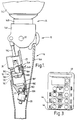
- FIG. 1 A lower limb prosthesis incorporating part of a control system in accordance with the invention is shown in Figure 1.
- the prosthesis has a knee joint 10 with a knee pivot 12 connecting a thigh component 14 to a shin component 16.
- the thigh component comprises a knee chassis 14A, an alignment device 14B, and a stump socket 14C.
- the shin component 16 has a conventional carbon fibre reinforced plastics shin cradle 16A which houses a piston and cylinder assembly 18 acting as a flexion control device.
- the assembly 18 comprises a cylinder 18A which is pivotally coupled to the posterior part of the shin cradle 16A and a piston 18B having a piston rod 18C which is pivotally coupled to the knee chassis 14A.
- the piston and cylinder assembly 18 is a pneumatic device, the resistance to flexion of the knee joint being controlled by a needle valve 18D which is adjustable by an electrical stepper motor 20 and an associated screw-threaded shaft 20A connected to the needle member of the needle valve.
- the needle valve 18D lies in a passage 18E in the body of the cylinder 18A, the passage 18E interconnecting the cylinder interior spaces 18F, 18G on opposite sides of the piston 18C, the passage emerging at a port 18H in the wall of the cylinder. Operation of the motor 20 causes the shaft 20A to move axially so that the needle member moves into or out of a passageway forming part of passage 18E.
- the passage 18E constitutes a first bypass passage interconnecting the cylinder spaces on opposite sides of the piston 18C.
- a second bypass passage 18I incorporating a valve such as a one-way valve 18J is formed in the piston 18C so that the needle valve 18D is effective only on one stroke of the piston, in this case the stroke corresponding to increasing flexion of the knee joint 10.
- the one-way valve 18J may be arranged so as not to close-off the second bypass passage 18I completely on the increasing flexion stroke, but rather merely to reduce the orifice area through the piston 18C.
- Such an arrangement has the effect of the needle valve 18D determining the resistance to motion of the piston 18C in both directions, i.e. for increasing and decreasing flexion, but with the effect of variations in the orifice area of the needle valve 18D being greater in one direction than the other, depending on the direction of operation of the valve 18J.
- stepper motor 20 and its threaded shaft 20A are mounted in the body of the cylinder 18, preferably adjacent the pivotal coupling 21 of the cylinder 18 to the shin 16.
- the stepper motor is driven by the combination of a microcomputer and receiver which together form assembly 22.
- the microcomputer determines knee flexion and extension movements by means of a magnetic proximity sensor comprising a first part, preferably a transducer 24A, mounted in or associated with the cylinder 18A (a second part, preferably) a permanent magnet 24B mounted on or associated with the piston 18B.
- the electronic circuitry 22 and the stepper motor 20 are powered by batteries, one of which is shown in Figure 1 and indicated by the reference 26.
- the receiver has a receiving antenna formed as a conductor track on the printed circuit board bearing components of the microcomputer and receiver.
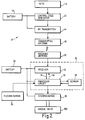
- the electronic circuitry 22 is shown in more detail in Figure 2. More particularly, the circuitry comprises the receiver 30 coupled to an antenna 28 and a processor circuit 32 which receives demodulated signals via input 34 and controls the receiver via output 36.
- a non-volatile memory in the form of an EEPROM 38 stores walking speed and valve setting data 38 produced by the processor circuit 32, and writes such data to the processor circuit 32 when required.
- the processor circuit 32 includes an output driver for driving the stepper motor 20 which in turn moves the needle valve 18D, and it has an input for receiving pulses from the flexion sensor 24 comprising transducer 24A and magnet 24B (See Figure 1).
- the receiver 30 preferably receives radio frequency (RF) signals via the receiving antenna 28 from an operator control unit 40 shown in block diagram form in Figure 2 and in plan view in Figure 3.
- the control unit 40 has a control code generator 42 responsive to operation of keys 44 on the face of the control unit 40.
- the control codes generated by the generator 42 are modulated and transmitted by an RF transmitter 46 which feeds RF output signals to a transmitting antenna 48 within the control unit 40 for transmission to the receiving antenna 28 on the limb.
- a battery 49 housed within the control unit 40 powers both control code generator 42 and the transmitter 46.
- the keys of the control unit 40 are divided into four groups.
- the first group comprises START and EXIT keys which are used by the prosthetist to start and exit a teach mode of the control system for programming optimum valve settings for different walking speeds.
- the receiver 30 on the limb has a beeper (not shown) which sounds whenever one of the keys 44 is pressed and a corresponding signal is received, allowing the prosthetist to check the receiver is on and within range.
- a second group of keys is for designating particular walking speeds.
- These SELECT SPEED keys comprise a SLOW key, a FAST key, and a NORM (normal) key.
- NORM normal
- the SLOW and FAST keys are used similarly for designating walking tests as slow and fast tests respectively.
- the prosthetist adjusts the swing phase resistance produced by the flexion control device using a group of ADJUST VALVE keys comprising an OPEN key and a CLOSE key for respectively decreasing swing resistance and increasing swing resistance.
- a SAVE key and a CANCEL key are used for saving optimum resistance (i.e. orifice size or area) settings and for erasing unwanted settings.
- the prosthetist can improve and, indeed, optimise the functioning of the control device at different limb operation speeds.
- the system is calibrated so as to be able to adjust the control device automatically to suit the individual wearer.
- the receiver 30 or processor circuit 32 may include means (not shown in the drawings) for giving a visual or audible signal when the receiver is switched on and/or when particular keys are pressed on the operator control unit.
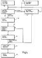
- FIG 4 shows start-up and shut-down phases of a program run by the microcomputer to cause the system to run in a teach mode
- activation of the receiver 30, which remains off during a playback mode of the system to save battery power, is performed by flexing the prosthesis at the knee in a particular manner. Specifically, the patient flexes the limb fully, counts 10 seconds, then extends the limb within 10 seconds, and flexes it again.
- the software causes the processor circuit 32 to monitor the receiver output (step 52) for a signal from the operator control unit. In the absence of any signal for longer than a predetermined period (e.g. 4 minutes), the processor circuit 32 causes the receiver to be switched off again (steps 54 and 56). Absence of the signal from the operator control unit also causes the processor to operate the playback routine (step 58), which will be described below.
- a predetermined period e.g. 4 minutes
- step 60 This is a procedure to allow the step motor and needle valve of the knee flexion control device to be set with respect to a predetermined reference position.
- the stepper motor 20 ( Figure 1) is fed with 40 valve closing step signals to move the needle valve 18D to the fully closed position. This is designated the zero reference position by the processor circuitry.
- a default value of a valve setting for the inactive state or slowest walking speed, or a previously saved valve setting for the inactive state or the slowest walking speed stored in the EEPROM store 38 is then read into the processor circuit 32 which has a "sitting and standing" register set up for the setting. This causes the stepper motor to move from the zero reference position to the appropriate valve setting.
- the valve homing procedure of step 60 is now complete. It has the result that the valve is set initially to a datum setting for sitting, standing, or slow movements.
- the processor circuit 32 now waits for the program START signal from the operator control unit (step 62). If this is received, the microprocessor circuit operates a teach routine (step 64) which will be described below. If not, the receiver is switched off. The end of the teach routine 64 also produces switching off of the receiver as represented by step 56, and the valve is homed again in step 66 (which is performed in the same manner as the valve homing step 60).
- the processor circuit 32 When the processor circuit 32 is operating in the teach mode, the processor circuit 32 continuously monitors movements of the limb in order to determine whether the limb is inactive, or, if the patient is walking or running, the speed of such walking or running.
- the flexion sensor is monitored in a monitoring step 70 insofar as pulses from the sensor are received in the microprocessor circuit 32. The spacing between the pulses is measured by a counter loop; (only two successive pulses are required to establish a measurement). These pulse intervals are processed to determine whether the movement of the limb is characteristic of the activation sequence described above. If so, the start-up routine 74 is activated (as described above with reference to Figure 4). In all other cases, a running average of the step period is calculated (step 76).
- step 78 a speed register set up by the processor circuit is reset (step 78) and the next step period is counted. If no movement is detected for a predetermined period such as four seconds, the circuit 32 is programmed to cause the stepper motor to drive the valve to a value stored in the EEPROM store for standing or sitting.
- Averaging may be performed by creating a predetermined number, e.g. six, of calculation registers and successively feeding them corresponding number (six) step period counts, each register commencing with a different step.
- a first calculation register receives the counts for, say, steps 1, 2, 3, 4, 5, and 6.
- the second calculation register stores the counts for steps 2, 3, 4, 5, 6, and 7,
- the third register receives the counts for steps 3, 4, 5, 6, 7, and 8, and so on, the contents of each register being added and divided to produce a respective average value so as to yield a running average by reading the successive calculated averages one after the other at the same rate as the registers are being filled.
- the average is calculated by counting how many steps are taken between resets of the registers, ignoring the first and second step periods, adding together the next four and dividing by four.
- Other methods of calculating a running average can be used.
- the running average is stored in a walking speed register which is being continuously updated with the new average values. In the teach mode, updating continues only so long as the values are representative of the patient walking.
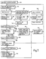
- the teach routine involves the basic operations of a prosthetist using the operator control unit to designate certain walking speeds as “slow”, "normal”, or “fast”, the patient being led through a series of walking tests at the different speeds while the opening of the needle valve of the flexion control device is adjusted by remote control using the operator control unit until a satisfactory gait is obtained in each case.
- the optimum valve settings so obtained are stored by "saving” corresponding signals, and performing calculations to derive intermediate values so that data is stored in "final” registers set up by the processor circuit 32 representing five speed ranges and five corresponding valve settings.
- the receiver is switched off (step 56, Figure 4) this data is read into the EEPROM (38 in Figure 2).
- the teach mode begins with checking for receipt of a CANCEL signal from the operator control unit (step 90), receipt of such a signal causes the final registers to be cleared and refilled from the EEPROM store (step 92).
- the program seeks a speed selection signal from the operator control unit. If this is received, a speed selection pointer is set either to slow, normal, or fast according to the signal received. In the absence of such a signal, the pointer defaults to normal (steps 94 and 96).
- step 98 the circuit looks for depression of either the OPEN (decrease resistance) or CLOSE (increase resistance) keys. Receipt of the signal corresponding to either causes the processor circuit to check the default settings of the standing and sitting register (referred to above in connection with the valve homing procedure) to determine the difference between the current valve position and the default setting so that the change in valve position resulting from one push of the OPEN key or CLOSE key is appropriately adjusted to the produce the same subjective effect substantially regardless of valve opening. Accordingly, if the current valve position is between, say, zero and 15 steps from the default position, a multiplier is set to cause the stepper motor to move at one step per key push.
- the stepper motor is caused to move at two steps per key push, and so on with increasing steps for increasing difference from the default value.
- the multiplier is set to produce a logarithmic relationship between the valve movement and the valve opening with respect to the default position.
- steps 98 and 100 are representative in Figure 6 by steps 98 and 100.
- a "selected position" register set up by the processor circuit 32 now receives the new valve setting, and the stepper motor is driven to cause the valve to move appropriately (steps 102 and 104). At this point the current value of the running average of the step period is read into a selected speed register representing the chosen designated speed (slow, normal, or fast) (step 106).
- the program checks for receipt of the SAVE signal from the operator control unit (step 108), and in the absence of such a signal returns to the beginning of the loop represented by steps 90 to 108.
- the teach routine allows the prosthetist to try a succession of different valve openings until the optimum setting is reached.
- the prosthetist presses the SAVE key to cause the program to proceed to step 110 in which the contents of the selected speed register, i.e. signals representing the last received running average step period and the last set valve position, are written to calculation registers.
- this step period and valve setting corresponds to just one of the selected speeds slow, normal, or fast.
- the calculation registers will already contain corresponding settings for the other two selected speeds, obtained either from previous walking tests or as default values.
- step 112 calculation of boundary values for five speed ranges and five valve settings.
- step periods measured for slow, normal, and fast walking tests are considered to represent the centre values of first, third, and fifth step period ranges
- step period values halfway between the slow and normal periods and normal and fast periods respectively are considered to represent the centre values of second and fourth step period ranges.
- the boundary values are calculated accordingly.
- the three valve settings obtained from the calculation registers are considered to represent the optimum valve settings for walking speeds corresponding to step periods within the first, third, and fifth ranges respectively, while settings midway between the valve settings stored in the calculation register are considered as the optimum settings for speeds corresponding to step periods within the second and fourth step period ranges.
- these intermediate valve settings are calculated in the calculation step 112.
- inactive and emergency settings of the valve are generated which correspond to the setting for the slowest speed range.
- This calculated step period range and valve setting data (five values for each plus inactive and emergency (low battery voltage) valve settings) are written to the final register each time a calculation is performed, i.e. after each SAVE command.
- the prosthetist may have completed the walking tests, in which case he presses the program EXIT key which is sensed by the processor circuit in its checking step 116, causing the contents of the final register to be read to the EEPROM store (step 118) hence the program continues with the shut-down routine represented by steps 56 and 66 of Figure 4 (step 120). If the prosthetist has not finished, no EXIT signal is received, and the teach routine is repeated from step 90 through to step 116 again.
- the EEPROM now contains stored data representing five valve settings for five consecutive speed ranges which represent the optimum settings for the individual patient and which can be used during normal use of the prosthesis. It will be appreciated that a different number of speed ranges and corresponding valve settings can be used, the step period and the valve setting values being calculated appropriately. Indeed, discrete ranges may be dispensed with and the results of the walking tests may be used to define a continuous relationship between walking speed and valve opening, i.e. so that the valve opening can be altered in a stepless manner.
- the processor circuit first monitors the flexion sensor in step 130 and measures and processes the output in step 132 so that, after checking whether the receiver is activated in step 134 (see the description above for the activation procedure), the speed register can be updated with what can be referred to as the instantaneous value of the step period providing the receiver is off (step 136).
- the playback routine causes each measured step period to be written directly to the speed register so that changes in the patient's pattern of movement can be picked up immediately.
- the receiver output is monitored (step 138) for the presence of a signal from the operator control unit. If a signal is detected, the valve homing procedure described above with reference to Fig. 4 (step 140) is carried out. In the absence of such a receiver output signal, the speed register is updated with the so-called instantaneous step period value and then, while the playback routine is operating, the receiver output is monitored over a period of time, here four minutes, for the presence of an operator control unit signal, as shown in Fig. 7 as step 142. If a receiver output signal is detected during this period, again, the valve homing procedure is carried out. If not, the receiver is switched off (step 144) and the playback routine continues.
- the detection 146 of a program start signal from the operator control unit via the receiver causes entry 148 into the teach routine described above with reference to Fig. 6. If no program start signal is detected, the receiver is switched off and the playback routine is continued.
- the next step in the playback routine is reading the speed register for the latest step period (step 150), followed by the comparison of the step period with zero (step 152).
- step 150 the contents of the speed register are zero so long as no flexion or extension is detected by the sensor 24A, 24B (Fig. 1) within a predetermined time interval.
- the prosthesis is considered to be inactive, in which case the inactive valve setting stored in the EEPROM store is read to a current valve register and the stepper motor is driven to the corresponding valve setting (steps 154, 156).
- the program then links back to step 132.
- the step period is compared with the boundary values of the step period ranges stored in the EEPROM (step 158) to determine whether the indicated range is different from the range already set in a select register (step 160). If no difference is detected, the program links back to the beginning of the playback routine. If a difference is detected, the select register is up-dated (step 162), the corresponding valve setting for the new range is read from the EEPROM store and written to the current valve register (step 164) and the motor is driven to the setting corresponding to the value in the current valve register (step 156). The program then returns back to the beginning of the playback routine.
- control system may be operable in a walking mode in which the system is operated as described above, and in a special mode in which the same steps are performed in the teach and playback routines, except that different values are used in the registers.
- the prosthetist selects the walking mode, and performs the teach routine as described above.
- the program EXIT signal is given, the system operates in a playback mode as described above, using the values programmed for walking stored in walking registers.
- the operator control unit has a further key or keys for selecting between the walking mode and the special mode. If, now, the prosthetist selects the special mode, then the teach routine can be performed with the patient performing special mode activities, and special mode data is stored in a new set of registers opened by the microprocessor.
- the patient is provided with a hand held mode selection controller allowing the receiver to be switched on, the desired mode to be selected, and the receiver to be switched off.
- the playback routine uses the contents of the new registers.
- the system has the advantage that since the operator control unit communicates via a wireless link the prosthetist can monitor the patient's performance from the most suitable position, and does not need to walk to the patient whenever a command signal is to be generated.
- Full automation of determination of walking speed and continuous measuring and updating of the walking speed by the processor circuit removes much of the effort involved in operating the prior art system for determining walking speed.
- the consequent significant simplification also reduces the extent of specialised training required of the prosthetist, and reduces the time necessary to reach optimum valve settings.
- the much reduced adjustment period significantly reduces the possibility of patient fatigue influencing the results.
- the adaptive prosthesis control system comprises an electrically adjustable knee flexion control device for mounting in a lower limb prosthesis with a knee joint for controlling movement of the joint, a step sensor for generating a walking step signal indicative of the step period during walking, an electronic processing circuit associated with and electrically coupled to the flexion control device and the step sensor, a receiver electrically coupled to the processing circuit for receiving electromagnetically or acoustically radiated command signals, and an operator unit arranged to generate and radiate the command signals.
- the command signals include flexion control device adjustment signals which are transmitted by the operator unit under the control of an operator.
- the processing circuit includes storage means, speed indicating means operable automatically both in a teach mode and a playback mode to convert the walking step signal periodically into a step period value, and control device setting means responsive during the teach mode to the adjustment signals picked up by the receiver to cause alteration of a parameter of the flexion control device and to generate signals indicative of a value of the parameter.
- the processing means further comprises saving means responsive to a further command signal received via the receiver from the operator unit to feed automatically to the storage means signals representative of the step period value and the parameter value associated with a selected instant in time for each of a plurality of different walking speeds in order to produce a set of stored data representing required parameter settings for the different speeds.
- the processing means also include playback means operable in the playback mode to cause the flexion control device parameter to be adjusted at required times in accordance with the step period values derived from walking step signals sensed at those times by the step sensor and in accordance with the corresponding parameter settings of the stored data.
- the system allows continuous processing and averaging of the walking speed or step period.
- the operator is able to alter the control device parameter by remote control, and to react in real time to each alteration by making further alterations.
- the processing means can be remotely commanded to "save" that setting and automatically to calculate a new set of control data based on the new setting and previous settings for other walking speeds.
- the processing means is thus able to perform on-line calculation of control data for use in the playback mode.
- the processing means on the limb is automatically able to gather and process data. All operator commands are carried out by remote control in the preferred system.
Description
Claims (24)
- An adaptive control system for an artificial limb, comprising a limb movement control device (18, 20) for mounting on the limb, a sensor (24A, 24B) for generating electrical sensor signals in response to movement of the limb, and an electronic processing circuit (32) which is electrically coupled to the sensor (24A, 24B) and the control device (18, 20), and which includes (a) data generating means operable in a teach mode and a playback mode of the processing circuit (32) automatically and repeatedly to generate measurement data values related to the speed of operation of the limb in response to the sensor signals, (b) control device setting means for adjusting a parameter of the control device (18, 20), and (c) storage means (38) for storing a set of control data representing a relationship between speed of limb operation and control device settings, the setting means being operable during the playback mode as the limb is operated to process the resulting said measurement data values in conjunction with the stored set of control data to generate the said setting signals for the control device (18, 20), whereby the control device (18, 20) is automatically adjusted according to the speed of the limb operation, characterised in that:the system further comprises a remote operator control unit (40) for the transmission of command signals to the limb, and a receiver (30) to form part of the limb and coupled to the processing circuit (32) for receiving the command signals,the control device setting means are operable in both modes to feed setting signals to the control device (18, 20) for adjusting the said parameter, such operation in the teach mode being to feed the setting signals to the control device (18, 20) according to parameter values generated in the processing circuit (32) in response to the command signals received by the processing circuit (32) via the receiver (30) from the remote control unit (40) for adjusting the control device parameter under operator control during operation of the limb, andthe processing circuit (32) includes means for processing the parameter values representing selected settings of the control device (18, 20) obtained during the teach mode together with the associated said measurement data values to generate automatically the set of control data representing a relationship between speed of limb operation and control device settings.
- A system according to claim 1, characterised in that the control device (18, 20) is a knee flexion control device for mounting in an above-knee lower limb prosthesis and wherein the control device parameter is the resistance to movement.
- A system according to claim 2, characterised in that the control device (18, 20) is a piston and cylinder assembly having a valve (18D) and a electric motor (20) coupled to the valve for altering the degree of opening of the valve.
- A system according to claim 2 or claim 3, characterised in that the sensor (24A, 24B) is arranged to produce pulsed sensor signals, one pulse being generated for each step taken.
- A system according to any preceding claim, characterised in that the operator remote control unit (40) includes a transmitter (46) for transmitting the command signals to the receiver (30) as electromagnetically radiated signals.
- A system according to any of claims 2 to 4, characterised in that the data generating means is operable continuously during the teach mode to generate measurement data values which are running averages of step periods as the limb is operated.
- A system according to any preceding claim, characterised in that the processing circuit (32) further includes saving means responsive to a further command signal received via the receiver (30) from the remote control unit (40) to feed automatically to the storage means (38) signals representative of the measurement data value and the parameter value associated with a selected instant in time for each of a plurality of different limb operation speeds.
- A system according to claim 7, characterised in that the said means for processing are operable in response to each operation of the saving means to calculate automatically a series of measurement data boundary values based on measurement data values selected during the teach mode to define a plurality of measurement data value ranges.
- A system according to claim 8, characterised in that the said means for processing are operable automatically to calculate interpolated parameter values to provide a set of parameter values to correspond to the measurement data value ranges.
- A system according to any preceding claim, characterised in that the remote control unit (40) has control means for increasing and decreasing the control device parameters.
- A system according to any preceding claim, characterised in that the processing circuit (32) is arranged to be mounted on the limb together with the sensor (24A, 24B) and the receiver (30).
- A system according to claim 3, characterised in that the sensor (24A, 24B) has a first part (24B) mounted on the piston of the piston and cylinder assembly (18, 20), and a second part (24A) mounted on the cylinder of the assembly.
- A system according to any preceding claim, characterised in that the means for processing include checking means for checking that the selected control device settings of the said set of control data are correctly ordered in magnitude with respect to the corresponding stored measurement data values.
- A method of controlling an artificial limb in which, during a teach phase, movement of the limb is automatically and repeatedly monitored by electronic means (32, 38) forming part of the limb with a series of measurement data values related to the speed of operation of the limb being generated in the electronic means (32, 38), and a set of control data derived from the said measurement data values and selected settings of a limb movement control device (18, 20) of the limb, and representing a relationship between speed of limb operation and control device settings, is then stored in the electronic means (32, 38), and in which method, during a playback phase, movement of the limb is automatically and repeatedly monitored by the electronic means (32, 38) to generate a series of measurement data values related to the speed of operation of the limb which are then processed by the electronic means (32, 38) in conjunction with the stored set of control data to generate appropriate control device setting signals for automatically adjusting the control device (18, 20) according to the speed of limb operation, characterised in that during the teach phase a remote control unit (40) is operated in conjunction with a receiver (30) forming part of the limb during operation of the limb to transmit command signals to the limb which are processed by the electronic means (32, 38) to generate setting signals for adjusting the limb movement control device (18, 20) with the object of improving limb operation, and data generated in the electronic means (32, 38) and representing the selected settings of the control device (18, 20) are processed in the electronic means (32, 38) together with the associated said measurement data values to generate automatically the set of control data.
- A method according to claim 14 for controlling knee movements of an above-knee lower limb prosthesis, characterised in that the selected settings of the control device (18, 20) correspond to different degrees of resistance to knee movement.
- A method according to claim 15, characterised in that the control device is a piston and cylinder assembly and wherein operation of the control device comprises driving an electric motor to alter the degree of opening of a valve in the assembly.
- A method according to claim 15 or claim 16, characterised in that the speed of operation of the limb is monitored using a sensor (24A, 24B) which produces a pulsed signal when the limb is operated, the electronic means (32, 38) measuring the pulse repetition rate.
- A method according to any of claims 14 to 17, characterised in that the command signals are transmitted to the receiver (30) as electromagnetic radiation.
- A method according to any of claims 15 to 17, characterised in that the measurement data values are continuously generated by the electronic means (32, 38) as a series of running averages of the step period during both the teach phase and the playback phase as the limb is operated.
- A method according to any of claims 14 to 19, characterised in that generating in the remote control unit (40) a further command signal, and, in the electronic means (32, 38), causing, in response to the further command signal, selection and storage of the measurement data value and the control device setting associated with the instant in time the further command signal is transmitted, whereby control device settings and measurement data values can be selected and saved for a plurality of different respective speeds of operation.
- A method according to claim 20, characterised in that the processing of the selected control device settings and measurement data values to generate the control data set is performed in response to the said saving.
- A method according to claim 20, characterised in that the processing of the selected control device settings and measurement data values comprises calculation of a series of measurement data boundary values based on the selected measurement data values to define a plurality of different consecutive measurement data value ranges, and in that the processing of the control device settings comprises calculating interpolated settings to provide a set of control device setting values to correspond to the measurement data value ranges.
- A method according to any of claims 14 to 22, characterised in that the command signals include control device incrementing signals for increasing or decreasing a parameter of the control device (18, 20) in steps.
- A lower limb prosthesis including the control device (18, 20), sensor (24A, 24B), processing circuit (32) and receiver (30) of the control system of claim 2, the control device (18, 20) being secured to a thigh component (14) and a shin component (16) of the prosthesis.
Applications Claiming Priority (2)
| Application Number | Priority Date | Filing Date | Title |
|---|---|---|---|
| GB939312131A GB9312131D0 (en) | 1993-06-11 | 1993-06-11 | Prosthesis control system |
| GB9312131 | 1993-06-11 |
Publications (3)
| Publication Number | Publication Date |
|---|---|
| EP0628296A2 EP0628296A2 (en) | 1994-12-14 |
| EP0628296A3 EP0628296A3 (en) | 1995-02-01 |
| EP0628296B1 true EP0628296B1 (en) | 1998-12-23 |
Family
ID=10737052
Family Applications (1)
| Application Number | Title | Priority Date | Filing Date |
|---|---|---|---|
| EP94303873A Expired - Lifetime EP0628296B1 (en) | 1993-06-11 | 1994-05-27 | Prosthesis control system |
Country Status (4)
| Country | Link |
|---|---|
| US (1) | US5893891A (en) |
| EP (1) | EP0628296B1 (en) |
| DE (1) | DE69415397T2 (en) |
| GB (1) | GB9312131D0 (en) |
Cited By (8)
| Publication number | Priority date | Publication date | Assignee | Title |
|---|---|---|---|---|
| US8323354B2 (en) | 2003-11-18 | 2012-12-04 | Victhom Human Bionics Inc. | Instrumented prosthetic foot |
| US8702811B2 (en) | 2005-09-01 | 2014-04-22 | össur hf | System and method for determining terrain transitions |
| US9060884B2 (en) | 2011-05-03 | 2015-06-23 | Victhom Human Bionics Inc. | Impedance simulating motion controller for orthotic and prosthetic applications |
| US9066818B2 (en) | 2009-11-13 | 2015-06-30 | Otto Bock Healthcare Products Gmbh | System comprising at least one orthopedic device and a remote control unit |
| US9271851B2 (en) | 2004-02-12 | 2016-03-01 | össur hf. | Systems and methods for actuating a prosthetic ankle |
| US9345591B2 (en) | 2004-03-10 | 2016-05-24 | össur hf | Control system and method for a prosthetic knee |
| US9351854B2 (en) | 2005-09-01 | 2016-05-31 | össur hf | Actuator assembly for prosthetic or orthotic joint |
| US9526636B2 (en) | 2003-11-18 | 2016-12-27 | Victhom Laboratory Inc. | Instrumented prosthetic foot |
Families Citing this family (108)
| Publication number | Priority date | Publication date | Assignee | Title |
|---|---|---|---|---|
| FR2735018B1 (en) * | 1995-06-09 | 1997-07-11 | Proteval | PNEUMATIC PROSTHETIC PART FOR THE KNEE JOINT |
| US5878745A (en) | 1996-03-01 | 1999-03-09 | Brain; Archibald I.J. | Gastro-laryngeal mask |
| US6113642A (en) | 1996-06-27 | 2000-09-05 | Mauch, Inc. | Computer controlled hydraulic resistance device for a prosthesis and other apparatus |
| GB9813904D0 (en) * | 1997-08-15 | 1998-08-26 | Blatchford & Sons Ltd | A lower limb prosthesis |
| DE19754690A1 (en) * | 1997-12-10 | 1999-07-01 | Biedermann Motech Gmbh | Leg prosthesis with an artificial knee joint with a control device |
| GB9727367D0 (en) | 1997-12-24 | 1998-02-25 | Brain Archibald Ian Jeremy | Improvements in laryngeal mask airway devices |
| GB9804611D0 (en) * | 1998-03-04 | 1998-04-29 | Blatchford & Sons Ltd | Lower limb prosthesis and control unit |
| GB9821771D0 (en) * | 1998-10-06 | 1998-12-02 | Brain Archibald Ian Jeremy | Improvements relating to laryngeal mask airway devices |
| DE19859931A1 (en) * | 1998-12-24 | 2000-07-06 | Biedermann Motech Gmbh | Prosthesis with an artificial knee joint and method for controlling a prosthetic leg |
| FI110159B (en) | 1999-12-17 | 2002-12-13 | Respecta Oy | Lower extremity prosthesis |
| DE10000781A1 (en) | 2000-01-11 | 2001-11-29 | Biedermann Motech Gmbh | Device and method for remote maintenance of an electronically controllable prosthesis |
| CN1237949C (en) * | 2000-01-20 | 2006-01-25 | 麻省理工学院 | Electronically controlled prosthetic knee |
| EP1880694B1 (en) * | 2000-03-29 | 2012-01-11 | Massachusetts Institute of Technology | Controllable prosthetic joint system |
| US7341603B2 (en) * | 2000-06-30 | 2008-03-11 | Applied Composite Technology, Inc. | Prosthetic foot with energy transfer including variable orifice |
| US6875241B2 (en) | 2000-06-30 | 2005-04-05 | Roland J. Christensen, As Operating Manager Of Rjc Development Lc, General Partner Of The Roland J. Christensen Family Limited Partnership | Variable resistance cell |
| US7686848B2 (en) * | 2000-06-30 | 2010-03-30 | Freedom Innovations, Llc | Prosthetic foot with energy transfer |
| US7572299B2 (en) * | 2000-06-30 | 2009-08-11 | Freedom Innovations, Llc | Prosthetic foot with energy transfer |
| US20060241783A1 (en) * | 2000-06-30 | 2006-10-26 | Christensen Roland J | Variable resistance cell |
| WO2002002034A1 (en) * | 2000-06-30 | 2002-01-10 | Roland J. Christensen, As Operating Manager Of Rjc Development, Lc, General Partner Of The Roland J. Christensen Family Limited Partnership | Prosthetic foot |
| US20050216098A1 (en) * | 2000-06-30 | 2005-09-29 | Roland J. Christensen | Variable resistance cell |
| GB2373884B8 (en) * | 2001-03-28 | 2006-05-04 | Nokia Corp | Method of configuring electronic devices |
| US6702858B2 (en) | 2002-05-15 | 2004-03-09 | Roland J. Christensen | Liner for prosthetic socket with variable viscosity fluid |
| US7736394B2 (en) * | 2002-08-22 | 2010-06-15 | Victhom Human Bionics Inc. | Actuated prosthesis for amputees |
| US7314490B2 (en) * | 2002-08-22 | 2008-01-01 | Victhom Human Bionics Inc. | Actuated leg prosthesis for above-knee amputees |
| AU2003250679B2 (en) * | 2002-08-22 | 2006-04-27 | Victhom Human Bionics Inc. | Positioning of lower extremities artificial proprioceptors |
| US7419509B2 (en) * | 2002-10-08 | 2008-09-02 | Freedom Innovations, Llc | Prosthetic foot with a resilient ankle |
| US6911052B2 (en) | 2002-10-08 | 2005-06-28 | Roland J. Christensen, As Operating Manager Of Rjc Development, Lc, General Partner Of The Roland J. Christensen Family Limited Partnership | Prosthetic foot with oblique attachment |
| US6929665B2 (en) * | 2002-10-08 | 2005-08-16 | Roland J. Christensen | Prosthetic foot with a resilient ankle |
| US6805717B2 (en) | 2002-10-08 | 2004-10-19 | Roland J. Christensen, As Operating Manager Of Rjc Development, Lc, General Manager Of The Roland J. Christensen Family Limited Partnership | Energy-storing prosthetic foot with elongated forefoot |
| US7186270B2 (en) * | 2002-10-15 | 2007-03-06 | Jeffrey Elkins 2002 Corporate Trust | Foot-operated controller |
| US7101487B2 (en) | 2003-05-02 | 2006-09-05 | Ossur Engineering, Inc. | Magnetorheological fluid compositions and prosthetic knees utilizing same |
| US7198071B2 (en) * | 2003-05-02 | 2007-04-03 | Össur Engineering, Inc. | Systems and methods of loading fluid in a prosthetic knee |
| US7347874B2 (en) * | 2003-07-11 | 2008-03-25 | Depuy Products, Inc. | In vivo joint implant cycle counter |
| US7520904B2 (en) * | 2003-10-21 | 2009-04-21 | Freedom Innovations, Llc | Prosthetic foot with an adjustable ankle and method |
| US6966933B2 (en) * | 2003-10-21 | 2005-11-22 | Roland J. Christensen, As Operating Manager Of Rjc Development, Lc, General Partner Of The Roland J. Christensen Family Limited Partnership | Prosthetic foot with an adjustable ankle and method |
| US7087090B2 (en) * | 2003-11-19 | 2006-08-08 | Bloorview Macmillan Centre | Artificial knee joint |
| WO2005079712A2 (en) * | 2004-02-12 | 2005-09-01 | össur hf | System and method for motion-controlled foot unit |
| US20060184280A1 (en) * | 2005-02-16 | 2006-08-17 | Magnus Oddsson | System and method of synchronizing mechatronic devices |
| US7172630B2 (en) * | 2004-02-20 | 2007-02-06 | Roland J. Christensen, As Operating Manager Of Rjc Development, Lc, General Partner Of The Roland J. Christensen Family Limited Partnership | Prosthetic foot with cam |
| US20050283257A1 (en) * | 2004-03-10 | 2005-12-22 | Bisbee Charles R Iii | Control system and method for a prosthetic knee |
| WO2005110293A2 (en) | 2004-05-07 | 2005-11-24 | Ossur Engineering, Inc. | Magnetorheologically actuated prosthetic knee |
| CA2863933C (en) | 2004-12-22 | 2018-08-07 | Ossur Hf | Systems and methods for processing limb motion |
| CN101151071B (en) | 2005-02-02 | 2010-12-08 | 奥瑟Hf公司 | Prosthetic and orthotic systems usable for rehabilitation |
| EP1843724B1 (en) | 2005-02-02 | 2018-07-25 | Össur hf | Sensing systems and methods for monitoring gait dynamics |
| US8801802B2 (en) | 2005-02-16 | 2014-08-12 | össur hf | System and method for data communication with a mechatronic device |
| SE528516C2 (en) | 2005-04-19 | 2006-12-05 | Lisa Gramnaes | Combined active and passive leg prosthesis system and a method for performing a movement cycle with such a system |
| GB0510951D0 (en) * | 2005-05-27 | 2005-07-06 | Laryngeal Mask Company The Ltd | Laryngeal mask airway device |
| US7507215B2 (en) | 2005-07-08 | 2009-03-24 | Jri Development Group, Llc | Orthotic brace |
| WO2007016781A1 (en) | 2005-08-10 | 2007-02-15 | Simon Fraser University | Methods and apparatus for harvesting biomechanical energy |
| US7485152B2 (en) * | 2005-08-26 | 2009-02-03 | The Ohio Willow Wood Company | Prosthetic leg having electronically controlled prosthetic knee with regenerative braking feature |
| US7531006B2 (en) * | 2005-09-01 | 2009-05-12 | össur hf | Sensing system and method for motion-controlled foot unit |
| US7717962B2 (en) * | 2006-03-22 | 2010-05-18 | Wilson Michael T | Proprioception enhancement device |
| EP1998723B1 (en) | 2006-03-24 | 2014-05-14 | Blatchford Products Limited | Lower limb prosthesis and control unit |
| US7618464B2 (en) * | 2006-08-03 | 2009-11-17 | Freedom Innovations, Llc | Prosthetic foot with variable medial/lateral stiffness |
| US7824446B2 (en) * | 2006-12-06 | 2010-11-02 | Freedom Innovations, Llc | Prosthetic foot with longer upper forefoot and shorter lower forefoot |
| CA2673915C (en) * | 2007-01-05 | 2016-06-28 | Victhom Human Bionics, Inc. | High torque active mechanism for orthotic and/or prosthetic devices |
| WO2008080231A1 (en) * | 2007-01-05 | 2008-07-10 | Victhom Human Bionics Inc. | Joint actuation mechanism for a prosthetic and/or orthotic device having a compliant transmission |
| EP2120801B1 (en) | 2007-01-19 | 2018-04-11 | Victhom Laboratory Inc. | Reactive layer control system for prosthetic and orthotic devices |
| US7727285B2 (en) * | 2007-01-30 | 2010-06-01 | Freedom Innovations, Llc | Prosthetic foot with variable medial/lateral stiffness |
| US8604709B2 (en) | 2007-07-31 | 2013-12-10 | Lsi Industries, Inc. | Methods and systems for controlling electrical power to DC loads |
| US8903577B2 (en) | 2009-10-30 | 2014-12-02 | Lsi Industries, Inc. | Traction system for electrically powered vehicles |
| US7598683B1 (en) | 2007-07-31 | 2009-10-06 | Lsi Industries, Inc. | Control of light intensity using pulses of a fixed duration and frequency |
| US7794506B2 (en) * | 2007-09-18 | 2010-09-14 | Freedom Innovations, Llc | Multi-axial prosthetic ankle |
| JP5443366B2 (en) * | 2007-10-11 | 2014-03-19 | ミルックス・ホールディング・エスエイ | System for treating patients with bowel disease |
| US20090234456A1 (en) * | 2008-03-14 | 2009-09-17 | Warsaw Orthopedic, Inc. | Intervertebral Implant and Methods of Implantation and Treatment |
| CN102036626B (en) | 2008-03-24 | 2014-07-02 | 奥瑟Hf公司 | Transfemoral prosthetic systems and methods for operating the same |
| US8034121B2 (en) * | 2008-04-18 | 2011-10-11 | Freedom Innovations, Llc | Prosthetic foot with two leaf-springs joined at heel and toe |
| US9351855B2 (en) | 2008-06-16 | 2016-05-31 | Ekso Bionics, Inc. | Powered lower extremity orthotic and method of operation |
| WO2010005473A1 (en) * | 2008-06-16 | 2010-01-14 | Berkeley Bionics | Semi-actuated transfemoral prosthetic knee |
| US8126736B2 (en) | 2009-01-23 | 2012-02-28 | Warsaw Orthopedic, Inc. | Methods and systems for diagnosing, treating, or tracking spinal disorders |
| US8685093B2 (en) | 2009-01-23 | 2014-04-01 | Warsaw Orthopedic, Inc. | Methods and systems for diagnosing, treating, or tracking spinal disorders |
| GB0903654D0 (en) | 2009-03-03 | 2009-04-15 | Laryngeal Mask Company The Ltd | Artificial airway device |
| US8128699B2 (en) * | 2009-03-13 | 2012-03-06 | Warsaw Orthopedic, Inc. | Spinal implant and methods of implantation and treatment |
| US9017418B2 (en) * | 2009-05-05 | 2015-04-28 | össur hf | Control systems and methods for prosthetic or orthotic devices |
| US9387096B2 (en) * | 2009-06-17 | 2016-07-12 | Ossur Hf | Feedback control systems and methods for prosthetic or orthotic devices |
| US9265904B2 (en) | 2009-07-06 | 2016-02-23 | Teleflex Life Sciences | Artificial airway |
| US9528897B2 (en) | 2009-08-13 | 2016-12-27 | Chimden Medical Pty Ltd | Pressure indicator |
| US8500825B2 (en) | 2010-06-29 | 2013-08-06 | Freedom Innovations, Llc | Prosthetic foot with floating forefoot keel |
| CN101889916B (en) * | 2010-07-26 | 2012-05-02 | 东南大学 | Electro-hydraulic damping cylinder device applied to intelligent knee joint |
| US8915968B2 (en) | 2010-09-29 | 2014-12-23 | össur hf | Prosthetic and orthotic devices and methods and systems for controlling the same |
| GB201016562D0 (en) | 2010-10-01 | 2010-11-17 | Laryngeal Mask Company The Ltd | Artificial airway device |
| JP5922135B2 (en) | 2010-10-15 | 2016-05-24 | ザ ラリンジアル マスク カンパニー リミテッド | Artificial airway device |
| US10549054B2 (en) | 2011-02-02 | 2020-02-04 | Teleflex Life Sciences Unlimited Company | Artificial airway |
| US8736087B2 (en) | 2011-09-01 | 2014-05-27 | Bionic Power Inc. | Methods and apparatus for control of biomechanical energy harvesting |
| US10543109B2 (en) | 2011-11-11 | 2020-01-28 | Össur Iceland Ehf | Prosthetic device and method with compliant linking member and actuating linking member |
| US9532877B2 (en) | 2011-11-11 | 2017-01-03 | Springactive, Inc. | Robotic device and method of using a parallel mechanism |
| GB201120628D0 (en) | 2011-11-30 | 2012-01-11 | Laryngeal Mask Company The Ltd | Endoscopy device |
| US9017419B1 (en) | 2012-03-09 | 2015-04-28 | össur hf | Linear actuator |
| EP2823791B1 (en) * | 2012-03-09 | 2016-09-28 | Nabtesco Corporation | Multi-articulated link knee joint |
| EP2825134B1 (en) * | 2012-03-14 | 2020-06-03 | Vanderbilt University | System and method for providing biomechanically suitable running gait in powered lower limb devices |
| US9044346B2 (en) | 2012-03-29 | 2015-06-02 | össur hf | Powered prosthetic hip joint |
| US20150125839A1 (en) * | 2012-07-27 | 2015-05-07 | Tillges Technologies Llc | Wireless communication for pressure sensor readings |
| DE102012107117A1 (en) * | 2012-08-02 | 2014-02-06 | Georg-August-Universität Göttingen Stiftung Öffentlichen Rechts | Orthesensteuerung |
| JP5709237B2 (en) * | 2012-08-30 | 2015-04-30 | ナブテスコ株式会社 | Sealed prosthetic leg |
| US10016290B2 (en) | 2012-09-17 | 2018-07-10 | Vanderbilt University | Walking controller for powered ankle prostheses |
| US9561118B2 (en) | 2013-02-26 | 2017-02-07 | össur hf | Prosthetic foot with enhanced stability and elastic energy return |
| US9028557B2 (en) | 2013-03-14 | 2015-05-12 | Freedom Innovations, Llc | Prosthetic with voice coil valve |
| WO2014159114A1 (en) | 2013-03-14 | 2014-10-02 | össur hf | Prosthetic ankle: a method of controlling based on adaptation to speed |
| US9849002B2 (en) | 2013-08-27 | 2017-12-26 | Freedom Innovations, Llc | Microprocessor controlled prosthetic ankle system for footwear and terrain adaptation |
| EP3128958B1 (en) | 2014-04-11 | 2019-08-07 | Össur HF | Prosthetic foot with removable flexible members |
| US10520557B2 (en) * | 2014-04-24 | 2019-12-31 | Arthrokinetic Institute, Llc | Systems, devices, and methods for recording and transmitting data |
| US20150320575A1 (en) * | 2014-05-07 | 2015-11-12 | The Regents Of The University Of California | Intuitive prosthetic interface |
| EP4257092A3 (en) | 2015-03-04 | 2024-01-24 | Ottobock Prosthetics, LLC | Lower limb prosthesis |
| EP3349697A1 (en) | 2015-09-18 | 2018-07-25 | Össur Iceland EHF | Magnetic locking mechanism for prosthetic or orthotic joints |
| US10195099B2 (en) | 2016-01-11 | 2019-02-05 | Bionic Power Inc. | Method and system for intermittently assisting body motion |
| JP7199155B2 (en) * | 2018-04-11 | 2023-01-05 | ナブテスコ株式会社 | multi-joint link knee joint |
| GB2576372B (en) | 2018-08-17 | 2023-02-01 | Blatchford Products Ltd | Lower limb prosthesis |
| JP2022099089A (en) * | 2020-12-22 | 2022-07-04 | ナブテスコ株式会社 | Artificial leg power consumption calculation system, artificial leg state estimation system, and artificial leg user physical condition estimation system |
Family Cites Families (5)
| Publication number | Priority date | Publication date | Assignee | Title |
|---|---|---|---|---|
| US4246661A (en) * | 1979-03-15 | 1981-01-27 | The Boeing Company | Digitally-controlled artificial hand |
| US5062856A (en) * | 1988-03-25 | 1991-11-05 | Kabushiki Kaisha Kobe Seiko Sho | Teaching playback swing-phase-controlled above-knee prosthesis |
| CA2008248A1 (en) * | 1989-01-24 | 1990-07-24 | Robert D. Singer | Electronic range of motion apparatus, for orthosis, prosthesis and cpm machine |
| US5062857A (en) * | 1990-06-05 | 1991-11-05 | Advanced Prosthestetics Development Corporation | Myoelectrically controlled knee joint locking device |
| JPH05337146A (en) * | 1992-06-09 | 1993-12-21 | Hyogo Pref Gov Shakai Fukushi Jigyodan | Leg play phase controlled artificial leg |
-
1993
- 1993-06-11 GB GB939312131A patent/GB9312131D0/en active Pending
-
1994
- 1994-05-27 EP EP94303873A patent/EP0628296B1/en not_active Expired - Lifetime
- 1994-05-27 DE DE69415397T patent/DE69415397T2/en not_active Expired - Fee Related
-
1997
- 1997-07-14 US US08/892,243 patent/US5893891A/en not_active Expired - Lifetime
Cited By (8)
| Publication number | Priority date | Publication date | Assignee | Title |
|---|---|---|---|---|
| US8323354B2 (en) | 2003-11-18 | 2012-12-04 | Victhom Human Bionics Inc. | Instrumented prosthetic foot |
| US9526636B2 (en) | 2003-11-18 | 2016-12-27 | Victhom Laboratory Inc. | Instrumented prosthetic foot |
| US9271851B2 (en) | 2004-02-12 | 2016-03-01 | össur hf. | Systems and methods for actuating a prosthetic ankle |
| US9345591B2 (en) | 2004-03-10 | 2016-05-24 | össur hf | Control system and method for a prosthetic knee |
| US8702811B2 (en) | 2005-09-01 | 2014-04-22 | össur hf | System and method for determining terrain transitions |
| US9351854B2 (en) | 2005-09-01 | 2016-05-31 | össur hf | Actuator assembly for prosthetic or orthotic joint |
| US9066818B2 (en) | 2009-11-13 | 2015-06-30 | Otto Bock Healthcare Products Gmbh | System comprising at least one orthopedic device and a remote control unit |
| US9060884B2 (en) | 2011-05-03 | 2015-06-23 | Victhom Human Bionics Inc. | Impedance simulating motion controller for orthotic and prosthetic applications |
Also Published As
| Publication number | Publication date |
|---|---|
| DE69415397D1 (en) | 1999-02-04 |
| DE69415397T2 (en) | 1999-05-12 |
| EP0628296A3 (en) | 1995-02-01 |
| US5893891A (en) | 1999-04-13 |
| EP0628296A2 (en) | 1994-12-14 |
| GB9312131D0 (en) | 1993-07-28 |
Similar Documents
| Publication | Publication Date | Title |
|---|---|---|
| EP0628296B1 (en) | Prosthesis control system | |
| EP1059898B1 (en) | Lower limb prosthesis and control unit | |
| US8403997B2 (en) | Lower limb prosthesis and control unit | |
| US6517585B1 (en) | Lower limb prosthesis | |
| US5443524A (en) | Teaching playback swing-phase-controlled above knee prosthesis | |
| WO2001017466A2 (en) | A lower limb prosthesis | |
| US4846180A (en) | Adjustable implantable heart stimulator and method of use | |
| GB2367753A (en) | A lower limb prosthesis | |
| CA1207066A (en) | Spout aimer | |
| EP0549855B1 (en) | System for controlling artificial knee joint action in an above knee prosthesis | |
| US6045331A (en) | Fluid pump speed controller | |
| EP0948759B1 (en) | Device in a process system for validating a control signal from a field device | |
| JP2700914B2 (en) | Terminal element | |
| EP1033637A3 (en) | Method and apparatus for optimizing overall characteristic of device, using heuristic method | |
| US20040006377A1 (en) | Tactile feedback for indicating validity of communication link with an implantable medical device | |
| GB2280609A (en) | Adaptive prosthesis control system | |
| RU95117936A (en) | METHOD FOR REGULATING POWER LEVEL IN COMMUNICATION SYSTEM, METHOD FOR REGULATING PRE-VALUED POWER LEVEL VALUE AND SYSTEM OF REGULATING POWER LEVEL | |
| EP0852030B1 (en) | Adaptive bias controller | |
| EP0783730B1 (en) | Non-linear control system for a single input-single output process | |
| US6625502B2 (en) | Automatic speed loop gain adjustment method and apparatus for a feedback control system | |
| CA2191170A1 (en) | Damper actuator controller having an enthalpy sensor input | |
| RU2125711C1 (en) | Transmitter with multifunctional adjustment | |
| Tessier et al. | Implementation of a fuzzy logic-based seeding depth control system | |
| CN115950070A (en) | Air valve control system and method | |
| CN117674681A (en) | Electric device and speed regulation control method |
Legal Events
| Date | Code | Title | Description |
|---|---|---|---|
| PUAI | Public reference made under article 153(3) epc to a published international application that has entered the european phase |
Free format text: ORIGINAL CODE: 0009012 |
|
| AK | Designated contracting states |
Kind code of ref document: A2 Designated state(s): DE ES FR IT NL SE |
|
| PUAL | Search report despatched |
Free format text: ORIGINAL CODE: 0009013 |
|
| AK | Designated contracting states |
Kind code of ref document: A3 Designated state(s): DE ES FR IT NL SE |
|
| 17P | Request for examination filed |
Effective date: 19950213 |
|
| 17Q | First examination report despatched |
Effective date: 19970509 |
|
| GRAG | Despatch of communication of intention to grant |
Free format text: ORIGINAL CODE: EPIDOS AGRA |
|
| GRAG | Despatch of communication of intention to grant |
Free format text: ORIGINAL CODE: EPIDOS AGRA |
|
| GRAH | Despatch of communication of intention to grant a patent |
Free format text: ORIGINAL CODE: EPIDOS IGRA |
|
| GRAH | Despatch of communication of intention to grant a patent |
Free format text: ORIGINAL CODE: EPIDOS IGRA |
|
| GRAA | (expected) grant |
Free format text: ORIGINAL CODE: 0009210 |
|
| AK | Designated contracting states |
Kind code of ref document: B1 Designated state(s): DE ES FR IT NL SE |
|
| PG25 | Lapsed in a contracting state [announced via postgrant information from national office to epo] |
Ref country code: NL Free format text: LAPSE BECAUSE OF FAILURE TO SUBMIT A TRANSLATION OF THE DESCRIPTION OR TO PAY THE FEE WITHIN THE PRESCRIBED TIME-LIMIT Effective date: 19981223 Ref country code: IT Free format text: LAPSE BECAUSE OF FAILURE TO SUBMIT A TRANSLATION OF THE DESCRIPTION OR TO PAY THE FEE WITHIN THE PRESCRIBED TIME-LIMIT;WARNING: LAPSES OF ITALIAN PATENTS WITH EFFECTIVE DATE BEFORE 2007 MAY HAVE OCCURRED AT ANY TIME BEFORE 2007. THE CORRECT EFFECTIVE DATE MAY BE DIFFERENT FROM THE ONE RECORDED. Effective date: 19981223 Ref country code: ES Free format text: THE PATENT HAS BEEN ANNULLED BY A DECISION OF A NATIONAL AUTHORITY Effective date: 19981223 |
|
| REF | Corresponds to: |
Ref document number: 69415397 Country of ref document: DE Date of ref document: 19990204 |
|
| PG25 | Lapsed in a contracting state [announced via postgrant information from national office to epo] |
Ref country code: SE Free format text: LAPSE BECAUSE OF FAILURE TO SUBMIT A TRANSLATION OF THE DESCRIPTION OR TO PAY THE FEE WITHIN THE PRESCRIBED TIME-LIMIT Effective date: 19990323 |
|
| ET | Fr: translation filed | ||
| NLV1 | Nl: lapsed or annulled due to failure to fulfill the requirements of art. 29p and 29m of the patents act | ||
| PLBE | No opposition filed within time limit |
Free format text: ORIGINAL CODE: 0009261 |
|
| STAA | Information on the status of an ep patent application or granted ep patent |
Free format text: STATUS: NO OPPOSITION FILED WITHIN TIME LIMIT |
|
| 26N | No opposition filed | ||
| PGFP | Annual fee paid to national office [announced via postgrant information from national office to epo] |
Ref country code: FR Payment date: 20010530 Year of fee payment: 8 |
|
| PGFP | Annual fee paid to national office [announced via postgrant information from national office to epo] |
Ref country code: DE Payment date: 20010619 Year of fee payment: 8 |
|
| PG25 | Lapsed in a contracting state [announced via postgrant information from national office to epo] |
Ref country code: DE Free format text: LAPSE BECAUSE OF NON-PAYMENT OF DUE FEES Effective date: 20021203 |
|
| PG25 | Lapsed in a contracting state [announced via postgrant information from national office to epo] |
Ref country code: FR Free format text: LAPSE BECAUSE OF NON-PAYMENT OF DUE FEES Effective date: 20030131 |
|
| REG | Reference to a national code |
Ref country code: FR Ref legal event code: ST |