EP0637754B1 - Battery capacity meter - Google Patents
Battery capacity meter Download PDFInfo
- Publication number
- EP0637754B1 EP0637754B1 EP94904766A EP94904766A EP0637754B1 EP 0637754 B1 EP0637754 B1 EP 0637754B1 EP 94904766 A EP94904766 A EP 94904766A EP 94904766 A EP94904766 A EP 94904766A EP 0637754 B1 EP0637754 B1 EP 0637754B1
- Authority
- EP
- European Patent Office
- Prior art keywords
- battery
- remaining capacity
- value
- current
- voltage
- Prior art date
- Legal status (The legal status is an assumption and is not a legal conclusion. Google has not performed a legal analysis and makes no representation as to the accuracy of the status listed.)
- Expired - Lifetime
Links
Images


Classifications
-
- G—PHYSICS
- G01—MEASURING; TESTING
- G01R—MEASURING ELECTRIC VARIABLES; MEASURING MAGNETIC VARIABLES
- G01R31/00—Arrangements for testing electric properties; Arrangements for locating electric faults; Arrangements for electrical testing characterised by what is being tested not provided for elsewhere
- G01R31/36—Arrangements for testing, measuring or monitoring the electrical condition of accumulators or electric batteries, e.g. capacity or state of charge [SoC]
- G01R31/3644—Constructional arrangements
- G01R31/3648—Constructional arrangements comprising digital calculation means, e.g. for performing an algorithm
-
- G—PHYSICS
- G01—MEASURING; TESTING
- G01R—MEASURING ELECTRIC VARIABLES; MEASURING MAGNETIC VARIABLES
- G01R31/00—Arrangements for testing electric properties; Arrangements for locating electric faults; Arrangements for electrical testing characterised by what is being tested not provided for elsewhere
- G01R31/36—Arrangements for testing, measuring or monitoring the electrical condition of accumulators or electric batteries, e.g. capacity or state of charge [SoC]
- G01R31/382—Arrangements for monitoring battery or accumulator variables, e.g. SoC
- G01R31/3842—Arrangements for monitoring battery or accumulator variables, e.g. SoC combining voltage and current measurements
-
- G—PHYSICS
- G01—MEASURING; TESTING
- G01R—MEASURING ELECTRIC VARIABLES; MEASURING MAGNETIC VARIABLES
- G01R31/00—Arrangements for testing electric properties; Arrangements for locating electric faults; Arrangements for electrical testing characterised by what is being tested not provided for elsewhere
- G01R31/005—Testing of electric installations on transport means
- G01R31/006—Testing of electric installations on transport means on road vehicles, e.g. automobiles or trucks
Definitions
- This invention relates to a remaining capacity meter of a battery to be used as a driving source for electric motor vehicles, and particularly to a battery remaining capacity meter with which a usable capacity of the battery being used can be easily understood.
- a battery is generally used as a driving source for an electric motor in an electric motor vehicle such as an electric car.
- Several different methods are known for detecting the remaining capacity of the battery. Such methods can be classified into either 1) direct detection or 2) indirect detection of the remaining capacity.
- the first classification uses the relationship between the following essential battery characteristics and the battery remaining capacity. These characteristics include the open circuit voltage. electrolyte density, the electrode potential of a pair of reference electrodes, the pH value of the electrolyte. partial pressures of various gases in the cell, relative humidity in the cell dead space, the electrolyte viscosity, and the refractive index of the electrolyte.
- a numerical formula representing the relation between these characteristics and the remaining capacity varies depending on the type of battery.
- a sealed lead acid battery is generally recognized to have a linear correlation between the remaining capacity and the open circuit voltage.
- a 13V open circuit voltage corresponds to 27Ah, 12.4V to 15Ah, and 11.8V to 2Ah.
- a remaining capacity meter using this correlation is described in detail in Japanese Patent Application Laid-open Print No. 57-149144.
- An apparatus based on the relation between the density and the refractive index of the sulfuric acid electrolyte of a lead acid battery has also been used widely to detect the remaining capacity (e.g.. Japanese Patent Application Laid-open Print No. 63-274064 and Japanese Patent Application Laid-open Print No. 1-260769).
- a special probe is inserted into the battery to measure the refractive index of the sulfuric acid electrolyte. The remaining capacity is calculated from the detected values.
- the second classification indirect detection of a remaining capacity calculates a remaining capacity by measuring either the output current of the battery or the output current and voltage of the battery when the battery is being used as an energy source.
- I stands for the discharge current
- n for a value larger than 1 which depends on the type of battery
- t for the discharge time
- C for a constant.
- the PEUKERT equation yields values which correspond to the well-known phenomenon in which battery capacity decreases as the electric current increases. For example, in a 30Ah sealed lead acid battery, a 10A constant current discharge leads to a capacity of 26.6Ah, 50A to 17.0Ah, and 80A to 14. 9Ah.
- a second indirect detection technique for determining battery remaining capacity uses the output current and the voltage of the battery (e.g., Japanese Patent Application Laid-open No. 2-247588). Specifically, in a table showing current on the horizontal axis and a voltage on the vertical axis, values corresponding to actual battery remaining capacities are indicated, and the table including these values is stored in a memory device which is a component of the remaining capacity meter.
- the direct detection technique which uses the open circuit voltage shows a correct value only when reaching an equilibrium voltage after an extended period of time.
- an electric motor vehicle such as an electric car actually runs in an urban area, it does not stop for long enough periods of time for the battery to reach the equilibrium voltage. As a result, the correct remaining value cannot be determined under these conditions.
- the insertion of the sensor for measuring the refractive index is expensive and has the disadvantage of increasing the possibility of electrolyte leakage from the point of sensor insertion. Additionally. it is difficult to position the sensor at an appropriate location within the battery such that a representative value can be measured.
- a method for detecting a remaining capacity which uses the PEUKERT equation to covert an input current signal, integrates the used battery capacity, and subtracts the integrated used capacity from the whole capacity, requires complicated circuitry which is expensive.
- Another problem with this method is that even when the battery has available remaining capacity, it may not be used for high current values because of large voltage drops. In this case, although the battery cannot be used because of the large voltage drops at that time, after a lapse of a certain time, the battery recovers and it may be used for high current values. In this case, the integration method indicates before and after recovery that there is no remaining capacity, causing the user to be confused. And, even if it is technically not an error, the remaining state of the battery is not indicated properly for both conditions, before and after recovery. That is to say, under the present method which uses the battery current, there is a disadvantage that the usable battery remaining capacity under all situations cannot be determined accurately.
- the indicating device either 1) indicating a capacity which varies greatly with the increase or decrease of current used or 2) indicates that remaining capacity can be used even when it cannot be used. In either case, the user has difficulty in understanding the indication of battery remaining capacity.
- this invention has been completed with the aim of realizing a battery remaining capacity meter using an inexpensive circuit structure, which can always make measurements regardless of the presence of a load, automatically corrects for differences in battery capacity due to the magnitude of a discharge current value. and always indicates a remaining capacity with respect to the current discharge current value. Furthermore, the capacity indication of the battery remaining capacity meter is designed to be similar to that of a fuel meter used in conventional internal combustion engine cars, so that the user can easily understand it.
- This invention provides a battery remaining capacity meter which comprises: a detecting means for detecting the discharge current and the terminal voltage of a battery, a data table of remaining capacity values of the battery, each of which corresponds to a respective combination of a discharge current and a terminal voltage, and in which the remaining capacity values are based on actual measurements, a memory for storing the above data table, and an indicating means for reading the remaining capacity value from the memory using the current value and the terminal voltage value of the operating battery and for controlling a display, wherein: the remaining capacity value defined as a percentage of the capacity of the battery in a fully charged state thereof is set as a ratio between a total time during which a constant current discharge can be made from an initial voltage in a fully charged state to an end voltage and a remaining time during which the constant current discharge can be made from the detected terminal voltage value to the end voltage.
- the battery terminal voltage varies with the respect to the discharge time, as shown in Fig. 11. Specifically, as shown in the figure, the terminal voltage decreases gradually for most of the discharge time, then decreases sharply at a time T when the usable capacity of the battery is exhausted. Therefore, the discharge capacity usable at a certain time for this discharge condition can be represented by the product of the discharge current and the elapsed time up until the voltage drop point T.
- the discharge time is shortened as the constant-current discharge value increases.
- the time T at which the voltage drops sharply decreases significantly with the increase of the constant current discharge.
- the voltage at the time T also tends to decrease.
- the dischargeable capacity decreases, and the discharge curves become different.
- the dischargeable capacity decreases as a function of each constant current.
- the dischargeable capacity decreases as the discharge current value increases.
- a discharge curve can be drawn using capacity instead of time on the horizontal axis and the terminal voltage on the vertical axis. Division of the voltage axis into several small ranges can generate the vertical component of a table which relates the dischargeable remaining capacity at a given time with the terminal voltage and the discharge current of the battery.
- a discharge current of 10A for example, a range from zero to time T on the horizontal axis is divided into five sections, so that a voltage range corresponding to each divided section can be obtained.
- the used current quantity (Ah) at this time can be calculated.
- the absolute remaining capacity value usable at each time can be obtained.
- a table for obtaining usable absolute capacity values of the battery can be obtained as shown in Fig. 15.
- Blocks (hereinafter referred to as cells) marked with an asterisk indicate that a combination of a given voltage and a given current cannot be attained.
- the absolute capacity values used in the aforementioned Fig. 15 are replaced by relative capacity values. And, as seen from the following examples and comparative examples, these relative values are used to realize a device which can simply determine the usable remaining capacity which varies according to the current values.
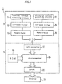
- a battery remaining capacity meter 1 comprises a detecting circuit block 3, a microcomputer block 5 connected to the above block, and a display 21 connected to the block 5.
- the detecting circuit block 3 is connected to the terminals of a battery which is not shown and comprises detecting circuits 11, 12 for detecting the battery current and voltage, filter circuits 13, 14 for filtering detection signals from these circuits 11, 12, and hold circuits 15, 16 for holding the filtered signals.
- the microcomputer block 5 comprises an A/D converter 17 for converting an analog signal from the detecting circuit into a digital signal, a microcomputer 18 for determining a battery remaining capacity value with reference to a table of a ROM 19 based on the digital signal, and a latch circuit for holding the remaining capacity value.
- the battery of this example is the aforementioned sealed lead acid battery having a nominal capacity of 30Ah to simplify the description.
- the above detecting circuits 11, 12 are connected to the battery terminals to detect the terminal voltage and the discharge current of the battery being used. Specifically, the terminal voltage is easily detected by resistance division. On the other hand, a discharge current can be detected by either a method using a shunt resistance connected in series with a load of the battery or a method using a current sensor with a Hall element.
- the detected analog signal having the a.c. component removed is converted into a digital signal by an A/D converter 17 through sample-hold circuits 15, 16 and outputted to the microcomputer 18.
- the microcomputer 18 reads the terminal voltage value and the discharge current value converted into the digital signal and obtains the remaining capacity value corresponding to a combination thereof from the ROM 19.
- the ROM (read-only memory) 19 has a data table of the remaining capacity value, to be described afterward, prepared based on values measured in advance and stored.
- the microcomputer 18 outputs binary data corresponding to the obtained remaining capacity value to a latch circuit 20.
- the binary data is data decoded to cause for example a display 21 to appropriately indicate the increase or decrease in the remaining capacity value.
- the latch circuit 20 is structured to hold the last data until new data comes from the microcomputer 18 and is output to the display 21.
- the display 21 indicates the increase or decrease of the remaining capacity value according to the data held in the latch circuit 20.
- a driving battery for electric-motor vehicles may be charged by regenerative braking when running.
- the remaining capacity value cannot be obtained from the data table in the ROM 19 because the battery is not discharged, and the discharge current and voltage values cannot be detected. Therefore, data of the microcomputer 10 is not outputted to the latch circuit 20 during this regeneration period. Accordingly, it is structured that during the period of regenerative braking, the remaining capacity value immediately before the regenerative braking is held and this remaining capacity value is indicated on the display 21.
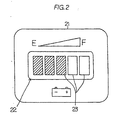
- the display 21 is provided with an LED module 22 consisting of five LEDs as shown in Fig. 2. These LEDs are arranged in a horizontal direction and designed to increase or decrease the number of illuminated LEDs from the left side in the figure according to the decoded data from the latch circuit 20. Specifically, when the remaining capacity value is 80% or more, the remaining capacity is determined to be F (full) and the display illuminates all five LEDs of the LED module 22. Similarly, when the remaining capacity value is 60% or more and less than 80%. four LEDs are illuminated. Thus, the number of illuminated LEDs is decreased by one at every 20%, and 0% or below is determined to be E (empty). In this condition, all LEDs are turned off. Therefore, in Fig. 2, three LEDs are illuminated, indicating that the battery remaining capacity at a certain current used is 40% or more and less than 60%.
- This invention is not limited to the indication of the increase or decrease of the illuminated number of LEDs of the display 21, but it may be structured to indicate by the increase or decrease of the display range, by a change of brightness, or by a change of a color.
- the above circuit structure is merely one example. and it may be a more simplified circuit structure by for example subjecting the detection data read in the microcomputer 18 to a digital low-pass filtering, so that the low-pass filters 13, 14 can be omitted.
- the sample-hold circuits 15, 16 may be one sample-hold circuit which is switched by time-sharing, so that further simplification can be made.
- an analog voltmeter may be used as the display.
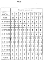
- the data table stored in the ROM 19 is prepared from the actually measured data shown in Fig. 15 and has the characteristic that a relative value is used instead of an absolute capacity value.
- the maximum capacity value at each discharge current is determined to be 100%, and the remaining capacity value determined from this current value and the detection voltage at this time is indicated as a percentage with respect to the maximum capacity value.
- the total discharge time of the time axis is divided according to the indicated percentages, and a voltage range corresponding to the division is determined.
- the voltage detection value decreases, and moves from a cell of 10A-12.3V to a cell of 80A-11.2 to 11.39V in the data table of Fig. 3.
- the remaining capacity value of both cells has a value of 100%, and the remaining capacity meter indicates 100%.
- the indication by the remaining capacity meter is constant regardless of the magnitude of the discharge current since the remaining capacity is in the fully charged state. Therefore, even when the discharge current is quickly brought back to 10A, the remaining capacity indication does not change and remains as 100%.
- the remaining capacity indication lowers to 80%, but when the current is increased to 80A, the voltage lowers to 11.0 to 11.19V, and the corresponding remaining capacity value remains the same at 80%.
- the indication of 80% capacity is the same and the indication itself is continuously indicated.
- the voltage range also changes, and a cell indicating the remaining capacity moves, but the indicated value of the cell remains 0%.
- the change of the indicated value due to the movement between cells in adjacent columns is horizontal or on a diagonal line and is continuously smooth such that the indication does not change suddenly, preventing the user from being confused unnecessarily.
- the above structure of the invention allows measurements of remaining capacity regardless of the presence or absence of a load.
- the realization of the battery remaining capacity meter in a simple circuit structure can improve cost efficiency.
- the battery remaining capacity meter of the invention has an advantage that it is not necessary to make a temperature compensation due to a change of the electrolyte temperature in view of its operation.
- the battery terminal voltage decreases with the decrease of the electromotive force and the increase of the internal resistance, and the rate of decrease of the terminal voltage is accelerated for a constant current discharge because the rate of electrolyte diffusion is slowed.
- these phenomena are automatically corrected as a decrease of the remaining capacity value as the rate of decrease of the terminal voltage accelerates.
- the degradation of the battery performance can be recognized as a reduction of the remaining capacity after full charging.
- a remaining capacity meter which uses a current value as one of several variables for determining the remaining capacity, it needs to incorporate a function for correcting the indication of a remaining capacity according to increases or decreases in the electric current.
- This invention measures both a discharge current and a terminal voltage of a battery to determine the remaining capacity. According to a combination of these measured current and voltage values, a ratio of the usable remaining capacity at that current value is determined with reference to the remaining capacity value stored in table form in the memory.
- the remaining capacity values stored in the data table of the invention correspond to relative values. A range indicating the relative remaining capacities ranges from 100% for the fully charged battery to 0% for the battery in the empty state.
- the dischargeable capacity at each discharge current is determined by discharging the battery from the fully charged state to the cut-off voltage of the empty state.
- the dischargeable capacity at each current is divided at equal intervals such as 100%, 90%, 80%, 70%, 60%, 50%, 40%, 30%, 20%, 10%, and 0%.
- the measured voltage at each uniform division point and the discharge current corresponding to it form one horizontal row of Fig. 3. Therefore, using the relative remaining capacity values (0 to 100%) of the invention, for the change of indication by the remaining capacity meter as a function of electric current, it can be clearly seen that the rate of decrease of the indicated values from 100% to 0% will be accelerated with increasing current.
- the battery remaining capacity meter of the invention will be described based on Example 2 shown in Fig. 5.
- the battery remaining capacity meter of this example has the same structure as that of Example 1 except that the data table stored in the memory means, ROM, is changed.
- this data table is prepared by modifying the data table of Fig. 3 used in Example 1. and consists of current values of the operating battery in the horizontal direction and percent divisions corresponding to the indication division of the display means in the vertical direction. And, each block divided by these current values and percentage covers a voltage range meeting the percentage condition at each current from the data table of Fig. 5.
- the battery remaining capacity is determined from the voltage value detected at the current used with reference to the table. Specifically, it is structured that the reference row of the table is determined from the current used, a block is determined from the applicable detected voltage value in this reference row, and the remaining capacity percentage line corresponding to this block is determined.
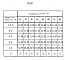
- the battery remaining capacity meter of the invention will be described based on Example 3 shown in Fig. 6.
- the battery remaining capacity meter of this example has the same circuit structure as that of Example 1 and Example 2 except that the data table stored in the memory means, ROM, is changed.
- this data table has the same structure as the data table of Example 2, and the voltage value of each block is the lower limit value of each corresponding block used in the data table of Example 2.
- the battery remaining capacity is determined from the voltage value detected at the current used with reference to the table. Specifically. the reference row of this table is first determined from the current used. Then, the detected voltage value and the voltage value of each block are compared, and the block Pn which meets the condition, Pn ⁇ detected voltage value ⁇ Pn+1, is determined as the applicable block. Lastly, the remaining capacity percentage corresponding to the applicable block is determined, and the increase or decrease corresponding to this percentage is indicated on the display.
- the battery remaining capacity meter of the invention will be described based on Example 4 shown in Fig. 7.
- the battery remaining capacity meter of this example has the same circuit structure as that of Example 1 except that the data table stored in the ROM 19 is changed.
- this data table has the same structure as the data table of Example 2, and the voltage value of each block is the upper limit value of each corresponding block used in the data table of Example 2.
- the battery remaining capacity is determined from the voltage value detected at the current used with reference to the table. Specifically, the reference row of this table is first determined from the current used. Then, the detected voltage value and the voltage.value of each block are compared, and the block Pn which meets the condition. Pn ⁇ detected voltage value ⁇ Pn+1. is determined as the applicable block. Lastly, the remaining capacity percentage corresponding to the applicable block is determined, and the increase or decrease corresponding to this percentage is indicated on the display.
- Example 3 the volume of data can be reduced, enabling simplification.
- Comparative Example 1 will be described with reference to Fig. 8.
- the same circuit structure of the battery remaining capacity meter as that shown in Fig. 1 of this invention will be used in this Comparative Example 1.
- the same display as that shown in Fig. 5 and used in Example 1 will be used.
- the structure for retaining the remaining capacity value immediately before the regenerative braking will be used in this Comparative Example 1.
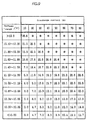
- the data table stored in the memory, ROM 19, is prepared based on the absolute capacity data of Fig. 15. But, to indicate the remaining capacity using five LED modules, it is necessary to correct the obtained absolute capacity value into a percentage ranging from 0% to 100%. Specifically, when the maximum value (26.6Ah at a constant discharge rate of 10Ah) of the absolute capacity is defined as 100%, other values in the table are set as a percentage of this maximum capacity value.
- the data table thus obtained and actually stored in the ROM 19 is shown in Fig. 8.
- the display corresponds to the measured current-voltage, indicating 80% at a 10A discharge current (12.1 to 12.3V) and 40% at an 80A discharge current (11.0 to 11.19V). After reaching the 0% limit, regardless of the discharge current, the indication becomes 0% at all current levels.
- the display indicates drastic changes in the capacity indicating value for different current values when the battery is fully charged or nearly fully charged. The drastic changes in the capacity indicating value due to a change of the current value becomes less drastic only as the battery gets closer to the empty state. Thus, on the whole. it is difficult for the user to understand the condition of the battery from this display.
- Comparative Example 2 will be described with reference to Fig. 9 and Fig. 10. Comparative Example 2 uses the same circuit structure and display as in Example 1 of the invention. Therefore, the remaining capacity value immediately before regenerative braking is retained during the regenerative braking.
- the data table stored in the ROM 19 is prepared from the absolute capacity data of Fig. 9.
- the maximum capacity at each discharge current is defined again as 26.6Ah. This value is the maximum capacity within a range of current actually used.
- the absolute capacity data defined in this way when the discharge current is high, remaining capacity is indicated even after the cut-off voltage is reached and capacity cannot be withdrawn at this high current.
- the display shows drastic changes in the capacity indicating value as a function of the discharge current when the battery approaches the empty state.
- the drastic changes in capacity due to a change of the current become less drastic only as the battery gets closer to the fully charged state.
- the remaining capacity meter of this Comparative Example it is difficult for the user to understand the indicated value of the remaining capacity.
- the invention structured as described above is suitable for a remaining capacity meter of a battery used as a driving source for an electric motor vehicle such as an electric car.
Abstract
Description
- This invention relates to a remaining capacity meter of a battery to be used as a driving source for electric motor vehicles, and particularly to a battery remaining capacity meter with which a usable capacity of the battery being used can be easily understood.
- A battery is generally used as a driving source for an electric motor in an electric motor vehicle such as an electric car. Several different methods are known for detecting the remaining capacity of the battery. Such methods can be classified into either 1) direct detection or 2) indirect detection of the remaining capacity.
- Specifically, the first classification uses the relationship between the following essential battery characteristics and the battery remaining capacity. These characteristics include the open circuit voltage. electrolyte density, the electrode potential of a pair of reference electrodes, the pH value of the electrolyte. partial pressures of various gases in the cell, relative humidity in the cell dead space, the electrolyte viscosity, and the refractive index of the electrolyte.
- A numerical formula representing the relation between these characteristics and the remaining capacity varies depending on the type of battery. Specifically, a sealed lead acid battery is generally recognized to have a linear correlation between the remaining capacity and the open circuit voltage. For example, in a 30-Ah sealed lead acid battery, a 13V open circuit voltage corresponds to 27Ah, 12.4V to 15Ah, and 11.8V to 2Ah. A remaining capacity meter using this correlation is described in detail in Japanese Patent Application Laid-open Print No. 57-149144.
- An apparatus based on the relation between the density and the refractive index of the sulfuric acid electrolyte of a lead acid battery has also been used widely to detect the remaining capacity (e.g.. Japanese Patent Application Laid-open Print No. 63-274064 and Japanese Patent Application Laid-open Print No. 1-260769). According to this method, a special probe is inserted into the battery to measure the refractive index of the sulfuric acid electrolyte. The remaining capacity is calculated from the detected values.
- The second classification, indirect detection of a remaining capacity, calculates a remaining capacity by measuring either the output current of the battery or the output current and voltage of the battery when the battery is being used as an energy source. This detection method mainly uses the well known PEUKERT equation, InT=C. In the formula, I stands for the discharge current, n for a value larger than 1 which depends on the type of battery, t for the discharge time, and C for a constant. The PEUKERT equation yields values which correspond to the well-known phenomenon in which battery capacity decreases as the electric current increases. For example, in a 30Ah sealed lead acid battery, a 10A constant current discharge leads to a capacity of 26.6Ah, 50A to 17.0Ah, and 80A to 14. 9Ah.
- Several remaining capacity meters have been published, which measure battery current, convert the detected output current value using the PEUKERT equation, and integrate the converted value with respect to time (e.g., Japanese Patent Application Laid-open No. 59-56177 and NASA Technical Note D-5773, 1970).
- A second indirect detection technique for determining battery remaining capacity uses the output current and the voltage of the battery (e.g., Japanese Patent Application Laid-open No. 2-247588). Specifically, in a table showing current on the horizontal axis and a voltage on the vertical axis, values corresponding to actual battery remaining capacities are indicated, and the table including these values is stored in a memory device which is a component of the remaining capacity meter.
- However, the above techniques for measuring the remaining capacity of a battery are not appropriate for conditions of actual use and have limitations with respect to accuracy and cost which remain to be solved.
- Specifically, the direct detection technique which uses the open circuit voltage shows a correct value only when reaching an equilibrium voltage after an extended period of time. However, when an electric motor vehicle such as an electric car actually runs in an urban area, it does not stop for long enough periods of time for the battery to reach the equilibrium voltage. As a result, the correct remaining value cannot be determined under these conditions.
- In the method for measuring the refractive index of the electrolyte with a sensor, the insertion of the sensor for measuring the refractive index is expensive and has the disadvantage of increasing the possibility of electrolyte leakage from the point of sensor insertion. Additionally. it is difficult to position the sensor at an appropriate location within the battery such that a representative value can be measured.
- Furthermore, a method for detecting a remaining capacity, which uses the PEUKERT equation to covert an input current signal, integrates the used battery capacity, and subtracts the integrated used capacity from the whole capacity, requires complicated circuitry which is expensive.
- It also has the disadvantage that large errors can occur under ordinary conditions of battery use. The errors of this method are cumulative and, thus, tend to increase with respect to the time of battery use. This tendency becomes particularly significant when the conditions of using the battery change drastically and frequently.
- To minimize the accumulation of errors, it is known in the art to provide a reset switch with which the battery remaining capacity meter resets to zero when the battery is fully charged. For a battery which is determined to be in a fully charged state when charged, the reset switch is triggered after charging is completed to initialize the battery remaining capacity meter and eliminate any previously accumulated errors.
- However, when a battery is partly charged, e.g. up to 60% of the total capacity by a quick charger, the reset switch is not triggered and accumulated errors remain. To minimize the accumulated errors, accurate integration of the reverse current during charging is necessary. But, since it is very hard to precisely execute integration of the reverse current, unacceptable errors can accumulate. The reason for this is that the charging efficiency of a battery is not constant and varies depending on the temperature and the charging conditions, so that the current fraction used for actual charging of the battery cannot be determined accurately. Furthermore, repetition of partial charging and discharging without triggering the reset switch may result in accumulated error which is unacceptable such that the remaining capacity meter may become useless.
- Another problem with this method is that even when the battery has available remaining capacity, it may not be used for high current values because of large voltage drops. In this case, although the battery cannot be used because of the large voltage drops at that time, after a lapse of a certain time, the battery recovers and it may be used for high current values. In this case, the integration method indicates before and after recovery that there is no remaining capacity, causing the user to be confused. And, even if it is technically not an error, the remaining state of the battery is not indicated properly for both conditions, before and after recovery. That is to say, under the present method which uses the battery current, there is a disadvantage that the usable battery remaining capacity under all situations cannot be determined accurately.
- In the aforementioned indirect detecting method (a method using a table based on the output current value and the voltage value of a battery), a remaining capacity can be estimated very accurately. However, with each value in the table representing an actual capacity value, the positional interval between a full charge indication and an empty charge indication will vary with the magnitude of the battery current used as indicated by the PEUKERT equation. Therefore, depending on the way in which the full charge state or empty charge state is defined, the indicating device either 1) indicating a capacity which varies greatly with the increase or decrease of current used or 2) indicates that remaining capacity can be used even when it cannot be used. In either case, the user has difficulty in understanding the indication of battery remaining capacity.
- In view of the circumstances, this invention has been completed with the aim of realizing a battery remaining capacity meter using an inexpensive circuit structure, which can always make measurements regardless of the presence of a load, automatically corrects for differences in battery capacity due to the magnitude of a discharge current value. and always indicates a remaining capacity with respect to the current discharge current value. Furthermore, the capacity indication of the battery remaining capacity meter is designed to be similar to that of a fuel meter used in conventional internal combustion engine cars, so that the user can easily understand it.
- This invention provides a battery remaining capacity meter which comprises: a detecting means for detecting the discharge current and the terminal voltage of a battery, a data table of remaining capacity values of the battery, each of which corresponds to a respective combination of a discharge current and a terminal voltage, and in which the remaining capacity values are based on actual measurements, a memory for storing the above data table, and an indicating means for reading the remaining capacity value from the memory using the current value and the terminal voltage value of the operating battery and for controlling a display, wherein: the remaining capacity value defined as a percentage of the capacity of the battery in a fully charged state thereof is set as a ratio between a total time during which a constant current discharge can be made from an initial voltage in a fully charged state to an end voltage and a remaining time during which the constant current discharge can be made from the detected terminal voltage value to the end voltage.
-
- [Fig. 1] A schematic view showing the entire circuit structure of the battery remaining capacity meter according to Example 1 of the invention.
- [Fig. 2] A front view showing the appearance of the display of Example 1.
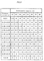
- [Fig. 3] A data table stored in the memory, ROM, of Example 1.
- [Fig. 4] An explanatory view showing the relation between a discharge curve at each current value and a graph representing the data table of Example 1.
- [Fig. 5] A data table stored in the memory, ROM, according to Example 2 of the invention.
- [Fig. 6] A data table stored in the memory, ROM, according to Example 3 of the invention.
- [Fig. 7] A data table stored in the memory, ROM, according to Example 4 of the invention.
- [Fig. 8] A data table stored in the memory, ROM, according to Comparative Example 1.
- [Fig. 9] A data table of battery absolute capacity values at each measured current value according to Comparative Example 2 (unusable capacities are included in this table).
- [Fig. 10] A data table stored in the memory, ROM, according to Comparative Example 2.
- [Fig. 11] A diagrammatic view showing a constant current discharge characteristic of an ordinary battery.
- [Fig. 12] A characteristic view showing each discharge curve at different constant current discharges.
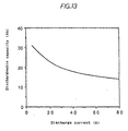
- [Fig. 13] A characteristic view showing the relation between a battery discharge current value and a dischargeable capacity.
- [Fig. 14] A characteristic view showing the relation between a battery discharge voltage and a dischargeable capacity based on the discharge curve at a given constant current discharge.
- [Fig. 15] A data table of battery absolute capacity values usable at each measured current value according to the invention.
-
- Prior to describing examples, known discharging characteristics of batteries will be described to make it easy to understand the invention.
- First, for example, when a sealed lead acid battery having a nominal capacity of 30Ah is discharged at a constant current from a fully charged state to the last stage of discharge, the battery terminal voltage varies with the respect to the discharge time, as shown in Fig. 11. Specifically, as shown in the figure, the terminal voltage decreases gradually for most of the discharge time, then decreases sharply at a time T when the usable capacity of the battery is exhausted. Therefore, the discharge capacity usable at a certain time for this discharge condition can be represented by the product of the discharge current and the elapsed time up until the voltage drop point T.
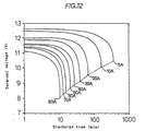
- Second, it is known according to the PEUKERT equation that the discharge time is shortened as the constant-current discharge value increases. Specifically, as shown in Fig. 12, the time T at which the voltage drops sharply decreases significantly with the increase of the constant current discharge. Furthermore, the voltage at the time T also tends to decrease. Accordingly, as the discharge current increases, the dischargeable capacity decreases, and the discharge curves become different. As a result, when a fully charged battery is discharged at several different constant currents, the whole dischargeable capacity varies according to the current, and the dischargeable capacity can be determined as a function of each constant current. Specifically, as shown in Fig. 13, for example in the same battery having a nominal capacity of 30Ah, the dischargeable capacity decreases as the discharge current value increases.
- At a certain constant current, a discharge curve can be drawn using capacity instead of time on the horizontal axis and the terminal voltage on the vertical axis. Division of the voltage axis into several small ranges can generate the vertical component of a table which relates the dischargeable remaining capacity at a given time with the terminal voltage and the discharge current of the battery.
- Specifically, as shown in Fig. 14, at a discharge current of 10A for example, a range from zero to time T on the horizontal axis is divided into five sections, so that a voltage range corresponding to each divided section can be obtained. Specifically, from the 10A discharge current value and the elapsed time to a certain divided time on the horizontal axis, the used current quantity (Ah) at this time can be calculated. And, by subtracting the used current value at each time from the whole used current value (Ah) calculated from the total elapsed time of discharging, the absolute remaining capacity value usable at each time can be obtained. By conducting this operation at every other current A, a table for obtaining usable absolute remaining capacity from each discharge current and measured voltage can be prepared.
- Thus, with respect to a battery having a capacity of 30Ah. a table for obtaining usable absolute capacity values of the battery can be obtained as shown in Fig. 15. Blocks (hereinafter referred to as cells) marked with an asterisk indicate that a combination of a given voltage and a given current cannot be attained.
- In this invention, the absolute capacity values used in the aforementioned Fig. 15 are replaced by relative capacity values. And, as seen from the following examples and comparative examples, these relative values are used to realize a device which can simply determine the usable remaining capacity which varies according to the current values.
- The battery remaining capacity meter of the invention will be described based on Example 1 shown in Fig. 1 and Fig. 3. Fig. 1 is the entire structural view of a device realizing the battery remaining capacity meter of this example. In the figure, a battery remaining
capacity meter 1 comprises a detectingcircuit block 3, a microcomputer block 5 connected to the above block, and adisplay 21 connected to the block 5. - Specifically, the detecting
circuit block 3 is connected to the terminals of a battery which is not shown and comprises detectingcircuits filter circuits circuits circuits 15, 16 for holding the filtered signals. And. the microcomputer block 5 comprises an A/D converter 17 for converting an analog signal from the detecting circuit into a digital signal, amicrocomputer 18 for determining a battery remaining capacity value with reference to a table of aROM 19 based on the digital signal, and a latch circuit for holding the remaining capacity value. The battery of this example is the aforementioned sealed lead acid battery having a nominal capacity of 30Ah to simplify the description. - The above detecting
circuits - These detected terminal voltage and discharge current have an a.c. component removed by low-
pass filters - The detected analog signal having the a.c. component removed is converted into a digital signal by an A/
D converter 17 through sample-hold circuits 15, 16 and outputted to themicrocomputer 18. - The
microcomputer 18 reads the terminal voltage value and the discharge current value converted into the digital signal and obtains the remaining capacity value corresponding to a combination thereof from theROM 19. The ROM (read-only memory) 19 has a data table of the remaining capacity value, to be described afterward, prepared based on values measured in advance and stored. And themicrocomputer 18 outputs binary data corresponding to the obtained remaining capacity value to alatch circuit 20. The binary data is data decoded to cause for example adisplay 21 to appropriately indicate the increase or decrease in the remaining capacity value. - The
latch circuit 20 is structured to hold the last data until new data comes from themicrocomputer 18 and is output to thedisplay 21. - The
display 21 indicates the increase or decrease of the remaining capacity value according to the data held in thelatch circuit 20. A driving battery for electric-motor vehicles may be charged by regenerative braking when running. When charging, the remaining capacity value cannot be obtained from the data table in theROM 19 because the battery is not discharged, and the discharge current and voltage values cannot be detected. Therefore, data of themicrocomputer 10 is not outputted to thelatch circuit 20 during this regeneration period. Accordingly, it is structured that during the period of regenerative braking, the remaining capacity value immediately before the regenerative braking is held and this remaining capacity value is indicated on thedisplay 21. - It does not matter whether or not regenerative braking can be detected according to a positive or negative current value, if an indication is used that regenerative braking is occurring by reasons of a separately received signal from a control circuit of the electric-motor vehicle.
- In this example, the
display 21 is provided with anLED module 22 consisting of five LEDs as shown in Fig. 2. These LEDs are arranged in a horizontal direction and designed to increase or decrease the number of illuminated LEDs from the left side in the figure according to the decoded data from thelatch circuit 20. Specifically, when the remaining capacity value is 80% or more, the remaining capacity is determined to be F (full) and the display illuminates all five LEDs of theLED module 22. Similarly, when the remaining capacity value is 60% or more and less than 80%. four LEDs are illuminated. Thus, the number of illuminated LEDs is decreased by one at every 20%, and 0% or below is determined to be E (empty). In this condition, all LEDs are turned off. Therefore, in Fig. 2, three LEDs are illuminated, indicating that the battery remaining capacity at a certain current used is 40% or more and less than 60%. - This invention is not limited to the indication of the increase or decrease of the illuminated number of LEDs of the
display 21, but it may be structured to indicate by the increase or decrease of the display range, by a change of brightness, or by a change of a color. - The above circuit structure is merely one example. and it may be a more simplified circuit structure by for example subjecting the detection data read in the
microcomputer 18 to a digital low-pass filtering, so that the low-pass filters hold circuits 15, 16 may be one sample-hold circuit which is switched by time-sharing, so that further simplification can be made. - In addition, for the indication of the increase or decrease by the display, when a D/A converter is used at the downstream of the latch circuit, an analog voltmeter may be used as the display.
- Further, it is to be understood that making modifications to the indicating method, such as giving an allowance to the indication by allowing the display to indicate the battery exhaustion state E (empty) before reaching the remaining
capacity 0% thereby securing safety, does not depart from the invention. - The data table stored in the
ROM 19 is prepared from the actually measured data shown in Fig. 15 and has the characteristic that a relative value is used instead of an absolute capacity value. - Specifically, in the data table shown in Fig. 3, after defining the maximum capacity value of each row as 100%, other values shown in the lower cells in the same column are defined and set as a percentage of the maximum capacity value. Specifically, the maximum capacity value at each discharge current is determined to be 100%, and the remaining capacity value determined from this current value and the detection voltage at this time is indicated as a percentage with respect to the maximum capacity value. Based on a discharge curve of voltage with respect to time for a given current value measured from an actual battery as shown in Fig. 14. the total discharge time of the time axis is divided according to the indicated percentages, and a voltage range corresponding to the division is determined. In other words, since the usable whole capacity varies according to each discharge current as shown in Fig. 4, according to this variable total capacity, the remaining capacity value at the discharge current for a given time is defined relatively as a percentage of the total capacity for a given current.
- Advantages of the battery remaining capacity meter using relative capacity values will be described with reference to the following examples.
- First, when a fully charged battery is discharged at a low discharge current of 10A, and then the discharge current is increased to 80A, the voltage detection value decreases, and moves from a cell of 10A-12.3V to a cell of 80A-11.2 to 11.39V in the data table of Fig. 3. The remaining capacity value of both cells has a value of 100%, and the remaining capacity meter indicates 100%. The indication by the remaining capacity meter is constant regardless of the magnitude of the discharge current since the remaining capacity is in the fully charged state. Therefore, even when the discharge current is quickly brought back to 10A, the remaining capacity indication does not change and remains as 100%. And, after the passage of a predetermined time under this discharge condition, when the detected current-voltage value becomes 10A-12.1 to 12.3V, the remaining capacity indication lowers to 80%, but when the current is increased to 80A, the voltage lowers to 11.0 to 11.19V, and the corresponding remaining capacity value remains the same at 80%. Thus, even when one discharge current changes to another discharge current, the indication of 80% capacity is the same and the indication itself is continuously indicated. Similarly, once 0% is reached at any discharge current and the indication value of its cell becomes 0%, when the discharge current is changed, the voltage range also changes, and a cell indicating the remaining capacity moves, but the indicated value of the cell remains 0%. Specifically, as shown in Fig. 3, the change of the indicated value due to the movement between cells in adjacent columns is horizontal or on a diagonal line and is continuously smooth such that the indication does not change suddenly, preventing the user from being confused unnecessarily.
- The above structure of the invention allows measurements of remaining capacity regardless of the presence or absence of a load.
- As shown above, differences in dischargeable capacity due to the magnitude of the battery discharge current value are automatically corrected, and the dischargeable capacity with respect to the present discharge current value can always be indicated correctly. And, since the battery is not over-discharged, the degradation of battery performance due to a careless misuse can be prevented, and the battery performance can be maximized.
- Further, the realization of the battery remaining capacity meter in a simple circuit structure can improve cost efficiency.
- In addition, the battery remaining capacity meter of the invention has an advantage that it is not necessary to make a temperature compensation due to a change of the electrolyte temperature in view of its operation. When the electrolyte temperature lowers, the battery terminal voltage decreases with the decrease of the electromotive force and the increase of the internal resistance, and the rate of decrease of the terminal voltage is accelerated for a constant current discharge because the rate of electrolyte diffusion is slowed. With the battery remaining capacity meter of the invention, these phenomena are automatically corrected as a decrease of the remaining capacity value as the rate of decrease of the terminal voltage accelerates. Also, the degradation of the battery performance can be recognized as a reduction of the remaining capacity after full charging.
- Furthermore, since a measured value immediately before the in-flow of an electric current to the battery is held and indicated for a period during which the electric current flows into the battery, it can handle the regenerative charge from regenerative braking in electric motor vehicles and related applications.
- As described above, since the usable battery remaining capacity decreases with the increase of a battery discharge current, a remaining capacity meter, which uses a current value as one of several variables for determining the remaining capacity, it needs to incorporate a function for correcting the indication of a remaining capacity according to increases or decreases in the electric current. This invention measures both a discharge current and a terminal voltage of a battery to determine the remaining capacity. According to a combination of these measured current and voltage values, a ratio of the usable remaining capacity at that current value is determined with reference to the remaining capacity value stored in table form in the memory. Specifically, the remaining capacity values stored in the data table of the invention correspond to relative values. A range indicating the relative remaining capacities ranges from 100% for the fully charged battery to 0% for the battery in the empty state. The dischargeable capacity at each discharge current is determined by discharging the battery from the fully charged state to the cut-off voltage of the empty state. The dischargeable capacity at each current is divided at equal intervals such as 100%, 90%, 80%, 70%, 60%, 50%, 40%, 30%, 20%, 10%, and 0%. The measured voltage at each uniform division point and the discharge current corresponding to it form one horizontal row of Fig. 3. Therefore, using the relative remaining capacity values (0 to 100%) of the invention, for the change of indication by the remaining capacity meter as a function of electric current, it can be clearly seen that the rate of decrease of the indicated values from 100% to 0% will be accelerated with increasing current. Thus, since a method, for correcting for capacity change as a function of electric current by the changing rate of decrease of the remaining capacity indicating values, is incorporated into the battery capacity meter, the value indicated as the battery remaining capacity value can be easily understood and grasped by the user. This is because its function is very similar to that of a fuel meter used in conventional internal combustion engine cars.
- The battery remaining capacity meter of the invention will be described based on Example 2 shown in Fig. 5. The battery remaining capacity meter of this example has the same structure as that of Example 1 except that the data table stored in the memory means, ROM, is changed.
- Specifically, as shown in Fig. 5, this data table is prepared by modifying the data table of Fig. 3 used in Example 1. and consists of current values of the operating battery in the horizontal direction and percent divisions corresponding to the indication division of the display means in the vertical direction. And, each block divided by these current values and percentage covers a voltage range meeting the percentage condition at each current from the data table of Fig. 5. When the battery is being used, the battery remaining capacity is determined from the voltage value detected at the current used with reference to the table. Specifically, it is structured that the reference row of the table is determined from the current used, a block is determined from the applicable detected voltage value in this reference row, and the remaining capacity percentage line corresponding to this block is determined.
- Therefore, the same effects as in the former example can be attained, and the volume of data can be reduced. enabling simplification.
- Further. the battery remaining capacity meter of the invention will be described based on Example 3 shown in Fig. 6. The battery remaining capacity meter of this example has the same circuit structure as that of Example 1 and Example 2 except that the data table stored in the memory means, ROM, is changed.
- Specifically, as shown in Fig. 6, this data table has the same structure as the data table of Example 2, and the voltage value of each block is the lower limit value of each corresponding block used in the data table of Example 2. And, when the battery is being used, the battery remaining capacity is determined from the voltage value detected at the current used with reference to the table. Specifically. the reference row of this table is first determined from the current used. Then, the detected voltage value and the voltage value of each block are compared, and the block Pn which meets the condition, Pn<detected voltage value<Pn+1, is determined as the applicable block. Lastly, the remaining capacity percentage corresponding to the applicable block is determined, and the increase or decrease corresponding to this percentage is indicated on the display.
- Therefore, the same effects as in the former example can be attained, and the volume of data can be reduced, enabling simplification.
- Further, the battery remaining capacity meter of the invention will be described based on Example 4 shown in Fig. 7. The battery remaining capacity meter of this example has the same circuit structure as that of Example 1 except that the data table stored in the
ROM 19 is changed. - Specifically, as shown in Fig. 7, this data table has the same structure as the data table of Example 2, and the voltage value of each block is the upper limit value of each corresponding block used in the data table of Example 2. And, when the battery is being used, the battery remaining capacity is determined from the voltage value detected at the current used with reference to the table. Specifically, the reference row of this table is first determined from the current used. Then, the detected voltage value and the voltage.value of each block are compared, and the block Pn which meets the condition. Pn<detected voltage value<Pn+1. is determined as the applicable block. Lastly, the remaining capacity percentage corresponding to the applicable block is determined, and the increase or decrease corresponding to this percentage is indicated on the display.
- Therefore, in the same way as Example 3, the volume of data can be reduced, enabling simplification.
- Now. Comparative Example 1 will be described with reference to Fig. 8. The same circuit structure of the battery remaining capacity meter as that shown in Fig. 1 of this invention will be used in this Comparative Example 1. The same display as that shown in Fig. 5 and used in Example 1 will be used. In addition, as described in Example 1, the structure for retaining the remaining capacity value immediately before the regenerative braking will be used in this Comparative Example 1.
- Specifically, the data table stored in the memory,
ROM 19, is prepared based on the absolute capacity data of Fig. 15. But, to indicate the remaining capacity using five LED modules, it is necessary to correct the obtained absolute capacity value into a percentage ranging from 0% to 100%. Specifically, when the maximum value (26.6Ah at a constant discharge rate of 10Ah) of the absolute capacity is defined as 100%, other values in the table are set as a percentage of this maximum capacity value. The data table thus obtained and actually stored in theROM 19 is shown in Fig. 8. - Disadvantages of using absolute capacity values will be shown for the operating conditions described below. First. a fully charged battery is discharged at a low discharge rate of 10A, and then the discharge rate is increased to 80A. In this case, since the absolute capacity value varies according to the discharge current, the indication of the remaining capacity meter is switched from 100% when discharged at 10A to 60% at 80A. And, when the discharge current is quickly brought back to 10A, the indication suddenly returns to 100% while passing through a state of 80%. Further, after the passage of a predetermined time under this discharging condition, the indication is reduced by one unit (20%). Although the indication remains same when the relative capacity value is used, in this case when the absolute capacity value is used, the display corresponds to the measured current-voltage, indicating 80% at a 10A discharge current (12.1 to 12.3V) and 40% at an 80A discharge current (11.0 to 11.19V). After reaching the 0% limit, regardless of the discharge current, the indication becomes 0% at all current levels. In general, the display indicates drastic changes in the capacity indicating value for different current values when the battery is fully charged or nearly fully charged. The drastic changes in the capacity indicating value due to a change of the current value becomes less drastic only as the battery gets closer to the empty state. Thus, on the whole. it is difficult for the user to understand the condition of the battery from this display.
- Comparative Example 2 will be described with reference to Fig. 9 and Fig. 10. Comparative Example 2 uses the same circuit structure and display as in Example 1 of the invention. Therefore, the remaining capacity value immediately before regenerative braking is retained during the regenerative braking.
- Specifically, the data table stored in the
ROM 19 is prepared from the absolute capacity data of Fig. 9. First. the maximum capacity at each discharge current is defined again as 26.6Ah. This value is the maximum capacity within a range of current actually used. For the absolute capacity data defined in this way, when the discharge current is high, remaining capacity is indicated even after the cut-off voltage is reached and capacity cannot be withdrawn at this high current. - As described in Comparative Example 2, to indicate the remaining capacity by five LED modules, it is necessary to scale the absolute capacity value to a percentage of 0% to 100%. Specifically, when the maximum absolute capacity value 26.6Ah is defined as 100%, other values in the figure are determined as a percentage of this maximum capacity value. Data obtained as a result and actually stored in the
ROM 19 is shown in Fig. 10. - Disadvantages of using the percentage indication of the absolute capacity value shown in Fig. 10 will be shown for the operating conditions described below. First, a fully charged battery is discharged at a low current discharge of 10A, and then at a large current discharge of 80A. In this case. when the maximum value of absolute capacity in each row of the table is defined as 100% regardless of the magnitude of the discharge current, the remaining capacity meter can indicate 100% at both of 10A discharge and 80A discharge. Specifically, even when the 80A discharge is quickly returned to 10A, the indicated value does not vary from 100%. And, after the passage of a predetermined time under this discharge condition, the indicated value is reduced by one unit (20%). It is easily seen that the remaining capacity indication output as a function of the current does not change drastically at this point. In this case, this is a result of the way in which the absolute capacity data is defined.
- However, when the battery is continuously discharged at a high discharge rate for a long period and then discharged at a low discharge rate, it can be recognized that the capacity reduces by one unit when the current is reduced to the lower rate. The disadvantage of using the absolute capacity value based on Fig. 10 becomes apparent as the battery gets closer to an empty state. Specifically, as seen from Fig. 10, when the battery is discharged at a high current rate, the actual battery capacity will reach the empty state even though the display value indicates a remaining capacity value of 40%. And, when discharged at an intermediate discharge rate, the battery will reach the empty state even though the display indicates a remaining capacity value of 20%. Even when the display indicates that the battery has an effective capacity, such a capacity is not available. As a result, the display shows drastic changes in the capacity indicating value as a function of the discharge current when the battery approaches the empty state. The drastic changes in capacity due to a change of the current become less drastic only as the battery gets closer to the fully charged state. As an overall result, when the remaining capacity meter of this Comparative Example is used, it is difficult for the user to understand the indicated value of the remaining capacity.
- The invention structured as described above is suitable for a remaining capacity meter of a battery used as a driving source for an electric motor vehicle such as an electric car.
Claims (6)
- A battery remaining capacity meter which comprises:characterized in that:a detecting means (3) for detecting the discharge current and the terminal voltage of a battery,a data table of remaining capacity values of the battery, each of which corresponds to a respective combination of a discharge current and a terminal voltage, and in which the remaining capacity values are based on actual measurements,a memory (19) for storing the above data table, andan indicating means (18) for reading the remaining capacity value from the memory using the current value and the terminal voltage value of the operating battery and for controlling a display (21),the remaining capacity value defined as a percentage of the capacity of the battery in a fully charged state thereof is set as a ratio between a total time during which a constant current discharge can be made from an initial voltage in a fully charged state to an end voltage and a remaining time during which the constant current discharge can be made from the detected terminal voltage value to the end voltage.
- A battery remaining capacity meter according to Claim 1, wherein the table stored in said memory (19) has each current value corresponding to usable conditions in one span of the table and a voltage value division divided into several small ranges corresponding to each current value in the other span of the table.
- A battery remaining capacity meter according to Claim 2, wherein the remaining capacity values corresponding to current values in said table has the maximum capacity value of each row defined as 100%, and other values in the same row defined as a percentage ratio with respect to the maximum capacity value.
- A battery remaining capacity meter according to Claim 3, wherein said display means (21) is provided with a prescribed number of light emission elements (23) and increases or decreases in the number of active light emission elements corresponding to the magnitude of said remaining capacity value.
- A battery remaining capacity meter according to Claim 4, wherein said remaining capacity value of from 0 to 100% is divided into a plurality of groups, the number of said groups agrees with the number of said light emission elements (23), and increases or decreases in the number of active light emission elements corresponding to the magnitude of said remaining capacity value.
- A battery remaining capacity meter according to Claim 1, wherein the remaining capacity value is determined from the terminal current and voltage value immediately before the in-flow of an electric current to the battery for a period during which the electric current flows into the battery by power regeneration.
Applications Claiming Priority (7)
| Application Number | Priority Date | Filing Date | Title |
|---|---|---|---|
| JP1196693 | 1993-01-27 | ||
| JP11966/93 | 1993-01-27 | ||
| JP5-11966U JPH0666209U (en) | 1993-02-22 | Mounting structure for the device mounting plate of the electrical equipment storage box | |
| JP126309/93 | 1993-05-27 | ||
| JP12630993 | 1993-05-27 | ||
| JP12630993 | 1993-05-27 | ||
| PCT/JP1994/000098 WO1994017425A1 (en) | 1993-01-27 | 1994-01-25 | Battery capacity meter |
Publications (3)
| Publication Number | Publication Date |
|---|---|
| EP0637754A1 EP0637754A1 (en) | 1995-02-08 |
| EP0637754A4 EP0637754A4 (en) | 1995-07-19 |
| EP0637754B1 true EP0637754B1 (en) | 2002-09-25 |
Family
ID=26347488
Family Applications (1)
| Application Number | Title | Priority Date | Filing Date |
|---|---|---|---|
| EP94904766A Expired - Lifetime EP0637754B1 (en) | 1993-01-27 | 1994-01-25 | Battery capacity meter |
Country Status (2)
| Country | Link |
|---|---|
| EP (1) | EP0637754B1 (en) |
| WO (1) | WO1994017425A1 (en) |
Cited By (12)
| Publication number | Priority date | Publication date | Assignee | Title |
|---|---|---|---|---|
| US6466025B1 (en) | 2000-01-13 | 2002-10-15 | Midtronics, Inc. | Alternator tester |
| US6466026B1 (en) | 2001-10-12 | 2002-10-15 | Keith S. Champlin | Programmable current exciter for measuring AC immittance of cells and batteries |
| US6469511B1 (en) | 2001-07-18 | 2002-10-22 | Midtronics, Inc. | Battery clamp with embedded environment sensor |
| US6495990B2 (en) | 1999-09-01 | 2002-12-17 | Keith S. Champlin | Method and apparatus for evaluating stored charge in an electrochemical cell or battery |
| US6544078B2 (en) | 2001-07-18 | 2003-04-08 | Midtronics, Inc. | Battery clamp with integrated current sensor |
| US6556019B2 (en) | 1999-04-30 | 2003-04-29 | Midtronics, Inc. | Electronic battery tester |
| US6566883B1 (en) | 1999-11-01 | 2003-05-20 | Midtronics, Inc. | Electronic battery tester |
| US6586941B2 (en) | 2000-03-27 | 2003-07-01 | Midtronics, Inc. | Battery tester with databus |
| US6633165B2 (en) | 1997-11-03 | 2003-10-14 | Midtronics, Inc. | In-vehicle battery monitor |
| US6696819B2 (en) | 2002-01-08 | 2004-02-24 | Midtronics, Inc. | Battery charge control device |
| US6707303B2 (en) | 1999-04-08 | 2004-03-16 | Midtronics, Inc. | Electronic battery tester |
| EP4194868A4 (en) * | 2021-01-08 | 2024-04-10 | Lg Energy Solution Ltd | Discharge voltage graph prediction method and battery system using same |
Families Citing this family (86)
| Publication number | Priority date | Publication date | Assignee | Title |
|---|---|---|---|---|
| TW300957B (en) * | 1994-11-21 | 1997-03-21 | Seiko Epson Corp | |
| FR2739452B1 (en) * | 1995-09-29 | 1997-11-14 | Renault | METHOD AND DEVICE FOR MEASURING THE STATE OF CHARGE OF A BATTERY |
| FR2740877B1 (en) * | 1995-11-06 | 1998-01-09 | Renault | METHOD FOR DETERMINING THE CHARGING STATE OF A BATTERY |
| US5764034A (en) * | 1996-04-10 | 1998-06-09 | Baxter International Inc. | Battery gauge for a battery operated infusion pump |
| US8872517B2 (en) | 1996-07-29 | 2014-10-28 | Midtronics, Inc. | Electronic battery tester with battery age input |
| US8198900B2 (en) | 1996-07-29 | 2012-06-12 | Midtronics, Inc. | Automotive battery charging system tester |
| US6445158B1 (en) | 1996-07-29 | 2002-09-03 | Midtronics, Inc. | Vehicle electrical system tester with encoded output |
| US6850037B2 (en) | 1997-11-03 | 2005-02-01 | Midtronics, Inc. | In-vehicle battery monitor |
| US7706991B2 (en) | 1996-07-29 | 2010-04-27 | Midtronics, Inc. | Alternator tester |
| US6351102B1 (en) | 1999-04-16 | 2002-02-26 | Midtronics, Inc. | Automotive battery charging system tester |
| IT1289764B1 (en) * | 1996-12-18 | 1998-10-16 | Fiat Auto Spa | METHOD OF DETERMINING THE CURRENT STATE OF CHARGE OF AN ELECTRICITY STORAGE UNIT |
| US5914605A (en) | 1997-01-13 | 1999-06-22 | Midtronics, Inc. | Electronic battery tester |
| GB2321315A (en) * | 1997-01-21 | 1998-07-22 | Silviu Puchianu | Estimating total working capacity of a battery |
| US6133709A (en) | 1997-01-21 | 2000-10-17 | Metrixx Limited | Signalling system |
| CA2294144A1 (en) * | 1997-06-19 | 1998-12-23 | Snap-On Equipment Limited | Battery testing and classification |
| US8958998B2 (en) | 1997-11-03 | 2015-02-17 | Midtronics, Inc. | Electronic battery tester with network communication |
| US7774151B2 (en) | 1997-11-03 | 2010-08-10 | Midtronics, Inc. | Wireless battery monitor |
| US7688074B2 (en) | 1997-11-03 | 2010-03-30 | Midtronics, Inc. | Energy management system for automotive vehicle |
| US7705602B2 (en) | 1997-11-03 | 2010-04-27 | Midtronics, Inc. | Automotive vehicle electrical system diagnostic device |
| US6259254B1 (en) | 1998-07-27 | 2001-07-10 | Midtronics, Inc. | Apparatus and method for carrying out diagnostic tests on batteries and for rapidly charging batteries |
| US6795782B2 (en) | 1999-04-08 | 2004-09-21 | Midtronics, Inc. | Battery test module |
| US6456045B1 (en) | 1999-04-16 | 2002-09-24 | Midtronics, Inc. | Integrated conductance and load test based electronic battery tester |
| AU2003200919B2 (en) * | 1999-05-05 | 2004-02-05 | Midtronics, Inc. | Energy management system for automotive vehicle |
| US6441585B1 (en) | 1999-06-16 | 2002-08-27 | Midtronics, Inc. | Apparatus and method for testing rechargeable energy storage batteries |
| US6737831B2 (en) | 1999-09-01 | 2004-05-18 | Keith S. Champlin | Method and apparatus using a circuit model to evaluate cell/battery parameters |
| US6363303B1 (en) * | 1999-11-01 | 2002-03-26 | Midtronics, Inc. | Alternator diagnostic system |
| US7398176B2 (en) | 2000-03-27 | 2008-07-08 | Midtronics, Inc. | Battery testers with secondary functionality |
| US8513949B2 (en) | 2000-03-27 | 2013-08-20 | Midtronics, Inc. | Electronic battery tester or charger with databus connection |
| US6759849B2 (en) | 2000-03-27 | 2004-07-06 | Kevin I. Bertness | Battery tester configured to receive a removable digital module |
| US7446536B2 (en) | 2000-03-27 | 2008-11-04 | Midtronics, Inc. | Scan tool for electronic battery tester |
| TW535308B (en) * | 2000-05-23 | 2003-06-01 | Canon Kk | Detecting method for detecting internal state of a rechargeable battery, detecting device for practicing said detecting method, and instrument provided with said |
| US6417669B1 (en) | 2001-06-11 | 2002-07-09 | Keith S. Champlin | Suppressing interference in AC measurements of cells, batteries and other electrical elements |
| US6788025B2 (en) | 2001-06-22 | 2004-09-07 | Midtronics, Inc. | Battery charger with booster pack |
| US7723993B2 (en) | 2002-09-05 | 2010-05-25 | Midtronics, Inc. | Electronic battery tester configured to predict a load test result based on open circuit voltage, temperature, cranking size rating, and a dynamic parameter |
| US6781382B2 (en) | 2002-12-05 | 2004-08-24 | Midtronics, Inc. | Electronic battery tester |
| US9255955B2 (en) | 2003-09-05 | 2016-02-09 | Midtronics, Inc. | Method and apparatus for measuring a parameter of a vehicle electrical system |
| US9018958B2 (en) | 2003-09-05 | 2015-04-28 | Midtronics, Inc. | Method and apparatus for measuring a parameter of a vehicle electrical system |
| US8164343B2 (en) | 2003-09-05 | 2012-04-24 | Midtronics, Inc. | Method and apparatus for measuring a parameter of a vehicle electrical system |
| US7154276B2 (en) | 2003-09-05 | 2006-12-26 | Midtronics, Inc. | Method and apparatus for measuring a parameter of a vehicle electrical system |
| US7977914B2 (en) | 2003-10-08 | 2011-07-12 | Midtronics, Inc. | Battery maintenance tool with probe light |
| US7777612B2 (en) | 2004-04-13 | 2010-08-17 | Midtronics, Inc. | Theft prevention device for automotive vehicle service centers |
| US7772850B2 (en) | 2004-07-12 | 2010-08-10 | Midtronics, Inc. | Wireless battery tester with information encryption means |
| US8344685B2 (en) | 2004-08-20 | 2013-01-01 | Midtronics, Inc. | System for automatically gathering battery information |
| US9496720B2 (en) | 2004-08-20 | 2016-11-15 | Midtronics, Inc. | System for automatically gathering battery information |
| US8436619B2 (en) | 2004-08-20 | 2013-05-07 | Midtronics, Inc. | Integrated tag reader and environment sensor |
| US8442877B2 (en) | 2004-08-20 | 2013-05-14 | Midtronics, Inc. | Simplification of inventory management |
| JP2006145285A (en) * | 2004-11-17 | 2006-06-08 | Ricoh Co Ltd | Battery residual charge detector |
| US7710119B2 (en) | 2004-12-09 | 2010-05-04 | Midtronics, Inc. | Battery tester that calculates its own reference values |
| US7791348B2 (en) | 2007-02-27 | 2010-09-07 | Midtronics, Inc. | Battery tester with promotion feature to promote use of the battery tester by providing the user with codes having redeemable value |
| US7808375B2 (en) | 2007-04-16 | 2010-10-05 | Midtronics, Inc. | Battery run down indicator |
| GB2463829B (en) | 2007-07-17 | 2012-11-21 | Midtronics Inc | Battery tester for electric vehicle |
| US9274157B2 (en) | 2007-07-17 | 2016-03-01 | Midtronics, Inc. | Battery tester for electric vehicle |
| US7928735B2 (en) * | 2007-07-23 | 2011-04-19 | Yung-Sheng Huang | Battery performance monitor |
| US8203345B2 (en) | 2007-12-06 | 2012-06-19 | Midtronics, Inc. | Storage battery and battery tester |
| FR2934374A1 (en) * | 2008-07-25 | 2010-01-29 | Continental Automotive France | Battery's e.g. lead-acid battery, maximum capacity determining method for motor vehicle, involves estimating value of maximum charge capacity of battery, where curve illustrating charge of battery based on charge state is straight line |
| US9588185B2 (en) | 2010-02-25 | 2017-03-07 | Keith S. Champlin | Method and apparatus for detecting cell deterioration in an electrochemical cell or battery |
| CN102804478B (en) | 2010-03-03 | 2015-12-16 | 密特电子公司 | For the watch-dog of front terminals battery |
| US9229062B2 (en) | 2010-05-27 | 2016-01-05 | Midtronics, Inc. | Electronic storage battery diagnostic system |
| US10046649B2 (en) | 2012-06-28 | 2018-08-14 | Midtronics, Inc. | Hybrid and electric vehicle battery pack maintenance device |
| US8738309B2 (en) | 2010-09-30 | 2014-05-27 | Midtronics, Inc. | Battery pack maintenance for electric vehicles |
| KR20130030766A (en) | 2010-06-03 | 2013-03-27 | 미드트로닉스, 인크. | Battery pack maintenance for electric vehicles |
| US11740294B2 (en) | 2010-06-03 | 2023-08-29 | Midtronics, Inc. | High use battery pack maintenance |
| US9419311B2 (en) | 2010-06-18 | 2016-08-16 | Midtronics, Inc. | Battery maintenance device with thermal buffer |
| US9201120B2 (en) | 2010-08-12 | 2015-12-01 | Midtronics, Inc. | Electronic battery tester for testing storage battery |
| JP5797004B2 (en) * | 2011-05-11 | 2015-10-21 | 本田技研工業株式会社 | Battery remaining amount estimation device for electric vehicle |
| WO2013070850A2 (en) | 2011-11-10 | 2013-05-16 | Midtronics, Inc. | Battery pack tester |
| US9851411B2 (en) | 2012-06-28 | 2017-12-26 | Keith S. Champlin | Suppressing HF cable oscillations during dynamic measurements of cells and batteries |
| US11325479B2 (en) | 2012-06-28 | 2022-05-10 | Midtronics, Inc. | Hybrid and electric vehicle battery maintenance device |
| CN102981124B (en) * | 2012-11-06 | 2014-08-20 | 清华大学 | Spot test method and test device for fuel cell stack membrane electrode conditions |
| US9244100B2 (en) | 2013-03-15 | 2016-01-26 | Midtronics, Inc. | Current clamp with jaw closure detection |
| US9312575B2 (en) | 2013-05-16 | 2016-04-12 | Midtronics, Inc. | Battery testing system and method |
| US10843574B2 (en) | 2013-12-12 | 2020-11-24 | Midtronics, Inc. | Calibration and programming of in-vehicle battery sensors |
| US9923289B2 (en) | 2014-01-16 | 2018-03-20 | Midtronics, Inc. | Battery clamp with endoskeleton design |
| US10473555B2 (en) | 2014-07-14 | 2019-11-12 | Midtronics, Inc. | Automotive maintenance system |
| US10222397B2 (en) | 2014-09-26 | 2019-03-05 | Midtronics, Inc. | Cable connector for electronic battery tester |
| WO2016123075A1 (en) | 2015-01-26 | 2016-08-04 | Midtronics, Inc. | Alternator tester |
| US9966676B2 (en) | 2015-09-28 | 2018-05-08 | Midtronics, Inc. | Kelvin connector adapter for storage battery |
| US10608353B2 (en) | 2016-06-28 | 2020-03-31 | Midtronics, Inc. | Battery clamp |
| US11054480B2 (en) | 2016-10-25 | 2021-07-06 | Midtronics, Inc. | Electrical load for electronic battery tester and electronic battery tester including such electrical load |
| US11513160B2 (en) | 2018-11-29 | 2022-11-29 | Midtronics, Inc. | Vehicle battery maintenance device |
| CN110412481A (en) * | 2019-07-26 | 2019-11-05 | 天能电池集团股份有限公司 | A kind of market battery after sale quickly detects determination method |
| US11566972B2 (en) | 2019-07-31 | 2023-01-31 | Midtronics, Inc. | Tire tread gauge using visual indicator |
| US11545839B2 (en) | 2019-11-05 | 2023-01-03 | Midtronics, Inc. | System for charging a series of connected batteries |
| US11668779B2 (en) | 2019-11-11 | 2023-06-06 | Midtronics, Inc. | Hybrid and electric vehicle battery pack maintenance device |
| US11474153B2 (en) | 2019-11-12 | 2022-10-18 | Midtronics, Inc. | Battery pack maintenance system |
| US11486930B2 (en) | 2020-01-23 | 2022-11-01 | Midtronics, Inc. | Electronic battery tester with battery clamp storage holsters |
Family Cites Families (6)
| Publication number | Priority date | Publication date | Assignee | Title |
|---|---|---|---|---|
| JPS5117699B1 (en) * | 1971-02-08 | 1976-06-04 | ||
| JPS56148076A (en) * | 1980-04-21 | 1981-11-17 | Olympus Optical Co Ltd | Battery checker |
| DE3624781A1 (en) * | 1985-08-03 | 1987-02-12 | Volkswagen Ag | Method for detecting the state of charge of a battery |
| JPS62237370A (en) * | 1986-04-07 | 1987-10-17 | Komatsu Ltd | Detector for residual quantity of electricity in battery |
| DE3736481C2 (en) * | 1987-10-28 | 1996-10-02 | Graesslin Kg | Method and device for determining the energy content of electrochemical energy stores |
| JP3087276B2 (en) * | 1989-03-20 | 2000-09-11 | スズキ株式会社 | Battery remaining capacity display |
-
1994
- 1994-01-25 EP EP94904766A patent/EP0637754B1/en not_active Expired - Lifetime
- 1994-01-25 WO PCT/JP1994/000098 patent/WO1994017425A1/en active IP Right Grant
Cited By (12)
| Publication number | Priority date | Publication date | Assignee | Title |
|---|---|---|---|---|
| US6633165B2 (en) | 1997-11-03 | 2003-10-14 | Midtronics, Inc. | In-vehicle battery monitor |
| US6707303B2 (en) | 1999-04-08 | 2004-03-16 | Midtronics, Inc. | Electronic battery tester |
| US6556019B2 (en) | 1999-04-30 | 2003-04-29 | Midtronics, Inc. | Electronic battery tester |
| US6495990B2 (en) | 1999-09-01 | 2002-12-17 | Keith S. Champlin | Method and apparatus for evaluating stored charge in an electrochemical cell or battery |
| US6566883B1 (en) | 1999-11-01 | 2003-05-20 | Midtronics, Inc. | Electronic battery tester |
| US6466025B1 (en) | 2000-01-13 | 2002-10-15 | Midtronics, Inc. | Alternator tester |
| US6586941B2 (en) | 2000-03-27 | 2003-07-01 | Midtronics, Inc. | Battery tester with databus |
| US6469511B1 (en) | 2001-07-18 | 2002-10-22 | Midtronics, Inc. | Battery clamp with embedded environment sensor |
| US6544078B2 (en) | 2001-07-18 | 2003-04-08 | Midtronics, Inc. | Battery clamp with integrated current sensor |
| US6466026B1 (en) | 2001-10-12 | 2002-10-15 | Keith S. Champlin | Programmable current exciter for measuring AC immittance of cells and batteries |
| US6696819B2 (en) | 2002-01-08 | 2004-02-24 | Midtronics, Inc. | Battery charge control device |
| EP4194868A4 (en) * | 2021-01-08 | 2024-04-10 | Lg Energy Solution Ltd | Discharge voltage graph prediction method and battery system using same |
Also Published As
| Publication number | Publication date |
|---|---|
| EP0637754A4 (en) | 1995-07-19 |
| WO1994017425A1 (en) | 1994-08-04 |
| EP0637754A1 (en) | 1995-02-08 |
Similar Documents
| Publication | Publication Date | Title |
|---|---|---|
| EP0637754B1 (en) | Battery capacity meter | |
| EP0713101B1 (en) | Remaining battery capacity meter and method for computing remaining capacity | |
| US4626765A (en) | Apparatus for indicating remaining battery capacity | |
| US7973534B2 (en) | Protection device for assembled battery, and battery pack unit | |
| US4377787A (en) | System for measuring state of charge of storage battery | |
| SU648147A3 (en) | Storage battery charge monitor | |
| CN100428559C (en) | Method and apparatus for estimating state of charge of secondary battery | |
| CN103138026B (en) | Battery pack control device | |
| US20060087291A1 (en) | Method of controlling rechargeable battery power and a power source apparatus | |
| EP0079788A1 (en) | Battery state of charge metering method and apparatus | |
| WO1990006522A1 (en) | State-of-charge indications | |
| CN103513183A (en) | Inspection system, charger/discharger, and inspection method of secondary battery | |
| CN102203628B (en) | Method for determining the charging state of a battery in a charging or discharging phase | |
| US4320334A (en) | Battery state-of-charge indicator | |
| JP4540029B2 (en) | Voltage detection method and voltage detection apparatus | |
| CN111216595B (en) | SOC calibration method of severe hybrid electric vehicle based on lithium battery equivalent circuit model | |
| JP3304507B2 (en) | Battery remaining capacity meter | |
| JP2000137062A (en) | Method and device for detecting residual capacity of secondary battery | |
| JP2003068369A (en) | Detecting method of total capacity of secondary battery and detector of total capacity | |
| US6094052A (en) | Survivor capacity measuring apparatus for a battery | |
| US7999553B2 (en) | Voltage measurement device and electric vehicle | |
| JPH06342044A (en) | Battery measuring apparatus | |
| Kordesch | Charging method for batteries, using the resistance-free voltage as endpoint indication | |
| JPH10106635A (en) | Battery pack condition detecting method | |
| JPS58117470A (en) | Battery monitor |
Legal Events
| Date | Code | Title | Description |
|---|---|---|---|
| PUAI | Public reference made under article 153(3) epc to a published international application that has entered the european phase |
Free format text: ORIGINAL CODE: 0009012 |
|
| 17P | Request for examination filed |
Effective date: 19941214 |
|
| AK | Designated contracting states |
Kind code of ref document: A1 Designated state(s): CH DE FR GB IT LI |
|
| RIN1 | Information on inventor provided before grant (corrected) |
Inventor name: MARRITT, WILLIAM, A., Inventor name: YAMAZAKI, TOSHIHIKO, Inventor name: KOUZAKI, MINORU, |
|
| A4 | Supplementary search report drawn up and despatched |
Effective date: 19950530 |
|
| AK | Designated contracting states |
Kind code of ref document: A4 Designated state(s): CH DE FR GB IT LI |
|
| 17Q | First examination report despatched |
Effective date: 20000211 |
|
| GRAG | Despatch of communication of intention to grant |
Free format text: ORIGINAL CODE: EPIDOS AGRA |
|
| GRAG | Despatch of communication of intention to grant |
Free format text: ORIGINAL CODE: EPIDOS AGRA |
|
| GRAH | Despatch of communication of intention to grant a patent |
Free format text: ORIGINAL CODE: EPIDOS IGRA |
|
| GRAH | Despatch of communication of intention to grant a patent |
Free format text: ORIGINAL CODE: EPIDOS IGRA |
|
| GRAA | (expected) grant |
Free format text: ORIGINAL CODE: 0009210 |
|
| AK | Designated contracting states |
Kind code of ref document: B1 Designated state(s): CH DE FR GB IT LI |
|
| REG | Reference to a national code |
Ref country code: GB Ref legal event code: FG4D |
|
| REG | Reference to a national code |
Ref country code: CH Ref legal event code: EP |
|
| REG | Reference to a national code |
Ref country code: CH Ref legal event code: NV Representative=s name: E. BLUM & CO. PATENTANWAELTE |
|
| REF | Corresponds to: |
Ref document number: 69431419 Country of ref document: DE Date of ref document: 20021031 |
|
| ET | Fr: translation filed | ||
| PLBE | No opposition filed within time limit |
Free format text: ORIGINAL CODE: 0009261 |
|
| STAA | Information on the status of an ep patent application or granted ep patent |
Free format text: STATUS: NO OPPOSITION FILED WITHIN TIME LIMIT |
|
| 26N | No opposition filed |
Effective date: 20030626 |
|
| PGFP | Annual fee paid to national office [announced via postgrant information from national office to epo] |
Ref country code: DE Payment date: 20070118 Year of fee payment: 14 |
|
| PGFP | Annual fee paid to national office [announced via postgrant information from national office to epo] |
Ref country code: GB Payment date: 20070124 Year of fee payment: 14 |
|
| REG | Reference to a national code |
Ref country code: CH Ref legal event code: PFA Owner name: SEIKO EPSON CORPORATION Free format text: SEIKO EPSON CORPORATION#4-1, NISHISHINJUKU 2-CHOME, SHINJUKU-KU#TOKYO 160-0811 (JP) -TRANSFER TO- SEIKO EPSON CORPORATION#4-1, NISHISHINJUKU 2-CHOME, SHINJUKU-KU#TOKYO 160-0811 (JP) |
|
| PGFP | Annual fee paid to national office [announced via postgrant information from national office to epo] |
Ref country code: FR Payment date: 20070109 Year of fee payment: 14 |
|
| GBPC | Gb: european patent ceased through non-payment of renewal fee |
Effective date: 20080125 |
|
| PG25 | Lapsed in a contracting state [announced via postgrant information from national office to epo] |
Ref country code: DE Free format text: LAPSE BECAUSE OF NON-PAYMENT OF DUE FEES Effective date: 20080801 |
|
| REG | Reference to a national code |
Ref country code: FR Ref legal event code: ST Effective date: 20081029 |
|
| PG25 | Lapsed in a contracting state [announced via postgrant information from national office to epo] |
Ref country code: GB Free format text: LAPSE BECAUSE OF NON-PAYMENT OF DUE FEES Effective date: 20080125 |
|
| PG25 | Lapsed in a contracting state [announced via postgrant information from national office to epo] |
Ref country code: FR Free format text: LAPSE BECAUSE OF NON-PAYMENT OF DUE FEES Effective date: 20080131 |
|
| PGFP | Annual fee paid to national office [announced via postgrant information from national office to epo] |
Ref country code: IT Payment date: 20120116 Year of fee payment: 19 |
|
| PGFP | Annual fee paid to national office [announced via postgrant information from national office to epo] |
Ref country code: CH Payment date: 20130114 Year of fee payment: 20 |
|
| REG | Reference to a national code |
Ref country code: CH Ref legal event code: PL |