EP0645243A2 - Refillable ink jet printing module - Google Patents
Refillable ink jet printing module Download PDFInfo
- Publication number
- EP0645243A2 EP0645243A2 EP94306684A EP94306684A EP0645243A2 EP 0645243 A2 EP0645243 A2 EP 0645243A2 EP 94306684 A EP94306684 A EP 94306684A EP 94306684 A EP94306684 A EP 94306684A EP 0645243 A2 EP0645243 A2 EP 0645243A2
- Authority
- EP
- European Patent Office
- Prior art keywords
- cartridge
- reservoir
- ink
- module
- printing module
- Prior art date
- Legal status (The legal status is an assumption and is not a legal conclusion. Google has not performed a legal analysis and makes no representation as to the accuracy of the status listed.)
- Granted
Links
Images


Classifications
-
- B—PERFORMING OPERATIONS; TRANSPORTING
- B41—PRINTING; LINING MACHINES; TYPEWRITERS; STAMPS
- B41J—TYPEWRITERS; SELECTIVE PRINTING MECHANISMS, i.e. MECHANISMS PRINTING OTHERWISE THAN FROM A FORME; CORRECTION OF TYPOGRAPHICAL ERRORS
- B41J2/00—Typewriters or selective printing mechanisms characterised by the printing or marking process for which they are designed
- B41J2/005—Typewriters or selective printing mechanisms characterised by the printing or marking process for which they are designed characterised by bringing liquid or particles selectively into contact with a printing material
- B41J2/01—Ink jet
- B41J2/17—Ink jet characterised by ink handling
- B41J2/175—Ink supply systems ; Circuit parts therefor
- B41J2/17503—Ink cartridges
- B41J2/17513—Inner structure
-
- B—PERFORMING OPERATIONS; TRANSPORTING
- B41—PRINTING; LINING MACHINES; TYPEWRITERS; STAMPS
- B41J—TYPEWRITERS; SELECTIVE PRINTING MECHANISMS, i.e. MECHANISMS PRINTING OTHERWISE THAN FROM A FORME; CORRECTION OF TYPOGRAPHICAL ERRORS
- B41J2/00—Typewriters or selective printing mechanisms characterised by the printing or marking process for which they are designed
- B41J2/005—Typewriters or selective printing mechanisms characterised by the printing or marking process for which they are designed characterised by bringing liquid or particles selectively into contact with a printing material
- B41J2/01—Ink jet
- B41J2/17—Ink jet characterised by ink handling
- B41J2/175—Ink supply systems ; Circuit parts therefor
- B41J2/17503—Ink cartridges
- B41J2/17506—Refilling of the cartridge
Definitions
- This invention relates to a refillable ink jet printing module, and more particularly to a so-called integrated thermal ink jet printing module comprising a thermal printing head integral with the associated reservoir for the ink, of the type removably mounted on the carriage of ink jet printers, for example those associated with a personal computer.
- Printing modules of the type mentioned are known in the art.
- an integral printing module which can be removably inserted in a printer is known from International (PCT) Patent Application WO 91/04861 published on April 18, 1991 (corresponding United States Patent 5,317,339 issued May 31, 1994).
- the reservoir for the ink contains a spongy body impregnated with ink, and the printing head is formed by a plate integral with the reservoir and provided with a plurality of nozzles from which the ink is expelled by means of a rapid increase in pressure in compression chambers connected to the nozzles.
- the working life of the ink contained in the reservoir is normally much shorter than the life of the head and it is therefore very expensive to replace a spent module with another one full of ink as this involves the loss of a printing head which is still in working order.
- the problem of the replacement of a spent integral module and the consequent loss of the associated printing head still in working order is particularly apparent in the case of the small printers associated with a portable (lap top) personal computer.
- the ink jet printing module generally has small dimensions and can contain approximately 6 cm3 of ink. It therefore has to be replaced more frequently than in the case of desk-top printers.
- the replacement of a spent integral module involves considerable practical problems, for instance the need to have a supply of new modules close at hand, thereby taking up more luggage space.
- An object of this invention is therefore to provide a thermal ink jet printing module capable of being refilled several times in order to make full use of the working life of the printing head associated therewith.
- Another object of the invention is to associate with a refillable ink jet printing module refill cartridges with small dimensions compared to the module to be refilled, thereby reducing the problems with the transportation and disposal of the spare cartridges.
- a thermal ink jet printing module of the type that can be removably mounted on the carriage of a printer, has an ink reservoir, and a thermal ink jet printing head fixed to and in communication with the reservoir.
- a housing is integral with the reservoir for receiving an ink refill cartridge for supplying the spent module with fresh ink, by means of a transfer element integral with the cartridge housing. In this way the reservoir can be refilled relatively easily by the user, even when the user is travelling.
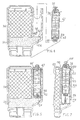
- a thermal ink jet printing module 10 embodying the invention is shown in vertical section.
- the module 10 is of the type which can be removably mounted on the carriage (not shown) of a printer and comprises a main reservoir 12 formed by four walls 14a, 14b, 14c and 14d (Fig. 3) and a base wall 16 (Fig. 1) which closes the reservoir 12 in the lower part and which is traversed by a hole 15 for the passage of the ink.
- a hollow sleeve 22 preferably of cylindrical shape, is fixed to the base wall 16 and extends towards the interior of the reservoir 12.
- An ink-permeable membrane 24 acting as a filter to hold back any impurities or air bubbles contained in the ink is disposed at the inlet 23 of the sleeve 22 directed towards the interior of the reservoir 12.
- the membrane 24 can be replaced by a layer of non-woven fabric or by a very close-meshed grate, e.g. of metal resistant to the corrosive action of the ink, or formed of plastic fibers.
- a thermal ink jet printing head 28 formed by a plate 29 of the multi-layer type constructed on a silicon base and having a plurality of nozzles 30 communicating with corresponding expulsion chambers, each connected to a duct for distributing the ink (not shown), is fixed to the outer face 26 of the base wall 16 in correspondence with the sleeve 22.
- the printing head 28 is of known type and further design features are described in Italian Patent No. 1 233 061.
- the reservoir 12 is filled with an absorbent material 34, for example, sponge, or a bundle of fibers, or even with a package of layers of non-woven fabric which is impregnated with ink upon construction of the module.
- an absorbent material 34 for example, sponge, or a bundle of fibers, or even with a package of layers of non-woven fabric which is impregnated with ink upon construction of the module.
- the absorbent material 34 is formed by a package of sheets or layers of non-woven fabric, a material known in the art, and sold under various names according to the constituent material, for example:
- These materials are formed by one or more layers of synthetic fibers arranged in a random manner on top of one another and welded together at contact points so as to form a flat structure similar to a sheet.
- the sheets, cut to the desired dimensions, are placed on top of one another in a well-defined quantity so as to form a package which is inserted into the reservoir.
- the package can be obtained by accordion-pleating a web of material of this kind having the desired width.
- the number of layers making up the package must be precisely determined, as varying this number (the thickness of the sheet being equal) results in greater or lesser compaction of the fibers and thus corresponding control of the capillarity developed.
- a layer of a slightly compressed spongy body 36 is inserted between the package 34 of non-woven fabric sheets and the membrane 24, its function being to ensure, by virtue of its own capillarity, that the ink flows towards the chamber 25 through the membrane 24.
- the module 10 is adapted to receive a refill cartridge which can be inserted in a simple manner in order to refill the reservoir 12 with fresh ink, and which can likewise be removed again in a simple manner for future refilling.
- a closure 48 connected perpendicularly to the walls 14d and 44b is disposed at the bottom of the space 46 and comprises a connecting gate 50 adapted to connect the cartridge 42 hydraulically to the main reservoir 12 when the cartridge is inserted into the space 46.
- the closure 48 has a hole 52 communicating with an intermediate duct 54 between the reservoir 12 and the connecting gate 50.
- the duct 54 communicates with the reservoir 12 via a passage 56 in the wall 14d, facing the lower part of the package of non-woven fabric sheets 34.
- the cartridge 42 is formed by a rigid casing 60 filled with ink and having a complementary shape to that of the space 46 into which it is to be inserted.
- the cartridge 42 comprises in the lower part an element 62 for transferring the ink and adapted to be connected to the member 50 when the cartridge 42 is inserted.
- the transfer element 62 is normally impervious to the ink, but permits ink flow when it is coupled to the connecting gate 50, so that the cartridge can be kept full of ink indefinitely, without the ink escaping through the element 62.
- the cartridge 42 is closed at the top by a cover 66 which comprises means 68 which can be actuated selectively to bring the casing 60 into communication with the atmosphere.
- the communication means 68 comprise an element movable with respect to the cover 66 and displaceable from a rest position in which the casing 60 is separated from the external atmosphere, to an operative position in which the casing 60 is brought into communication with the external atmosphere, as will be explained more clearly hereinafter.
- the communication means 68 comprise in particular a hollow cylindrical body 72 slidable in the cover 66 and having an outer end 74 in the form of a button, while the end 76 directed towards the interior of the casing 60 is shaped like a nail or claw (Fig. 2), its function being to break open a diaphragm 78 of the cover 66.
- the connecting gate 50 comprises a coupling member in the form of a hollow tubular element or pin 53 fixed to the closure 48 and coaxial with the hole 52, while the transfer element 62 comprises a cap 63 of soft impermeable material which can be pierced by the pin 53.
- the operator inserts a new cartridge fully into the space 46 (Fig. 2), piercing the cap 63 with the pin 53 and simultaneously pressing the button 74, pushing it into the operative position 75, so that the diaphragm 78 is penetrated and ruptured.
- the upper part of the casing 60 is thus brought into communication with the atmosphere, thereby allowing the ink in the ink-containing chamber in the cartridge 42 to descend by gravity in the duct 54 and to be absorbed by capillarity by the package 34 of absorbent material.
- the casing 60 of the cartridge 42 comprises an outwardly-projecting projection 80 (Fig. 1) which engages a corresponding groove 82 in the wall 44b when the cartridge is fully inserted in the space 46.
- the elastic compliance of the wall 44b allows for the passage of the projection 80 into the section 84 preceding the groove 82.
- FIGS 4 and 5 show another module 10 and cartridge associated therewith embodying this invention.
- the spongy body 36 extends into the duct 54 and is visible through the hole 52.
- the transfer element 62 comprises a fibrous or spongy member 88 inserted into the bottom of the cartridge 42 instead of the cap 63 of Fig. 1.
- the fibrous member 88 freed of the protective cap, comes into contact via the hole 52 with the spongy body 36, which is normally still impregnated with ink and, by virtue of the capillary action of the member 88 and the body 36, the ink of the cartridge 42 flows into the package 34 through the spongy body 36.
- Fig. 6 shows another variant of the module 10 and the associated cartridge 42 compared to the embodiments described hereinbefore.
- elements identical to those of the preceding figures are not described again in detail or numbered.
- the cover 90 of the module 10 extends over the upper orifice of a space 92 equivalent to the space 46 of Fig. 1.
- a hollow cylindrical sleeve 94 is fixed to the cover 90 and extends in the interior of the space 92.
- the sleeve 94 is closed at the bottom by a wall 96 provided with a hollow pin 98 communicating with the inner part of the space 92 below the sleeve 94.
- a refill cartridge 100 is provided in its lower part with a tubular element 102 closed by a cap 104, similar to the cap 63 of Fig. 1.
- the tubular element 102 is inserted into the sleeve 94, and once the cap 104 and the diaphragm 78 of the cartridge have been pierced, the ink contained in the cartridge can flow into the reservoir 12.
- Fig. 7 shows another method of coupling a refill cartridge 110 to a module 112 according to another embodiment of this invention.
- the new module 112 is already provided at the time of manufacture with the cartridge 110, either of the type shown in Fig. 1 or of the type shown in Fig. 4, inserted into the space 116, but, in this embodiment, the cartridge 110 is kept at a distance from the coupling member 118 by the engagement of an external projection 120 of the cartridge with a first groove 122 formed in a wall 126 of the space 116.
- the refill operation is simplified to the maximum.
- the operator has only to press a button 128 in order to push the cartridge into the bottom of the space 116 and to open the diaphragm 78, so that the cartridge is displaced into the position shown in Fig. 2 and is held in this position by the engagement of the projection 120 with a second groove 123 disposed in a lower position with respect to the groove 122.
- the volume of ink contained in a cartridge is kept in a ratio of approximately 1/3 of the volume of ink contained in a new module, which, as already stated above, will be around 5-6 cm3. Consequently, the external dimensions of each cartridge will also be in a similar ratio with respect to the dimensions of the module to be refilled.
Abstract
Description
- This invention relates to a refillable ink jet printing module, and more particularly to a so-called integrated thermal ink jet printing module comprising a thermal printing head integral with the associated reservoir for the ink, of the type removably mounted on the carriage of ink jet printers, for example those associated with a personal computer.
- Printing modules of the type mentioned are known in the art. For example an integral printing module which can be removably inserted in a printer is known from International (PCT) Patent Application WO 91/04861 published on April 18, 1991 (corresponding United States Patent 5,317,339 issued May 31, 1994). The reservoir for the ink contains a spongy body impregnated with ink, and the printing head is formed by a plate integral with the reservoir and provided with a plurality of nozzles from which the ink is expelled by means of a rapid increase in pressure in compression chambers connected to the nozzles.
- The working life of the ink contained in the reservoir is normally much shorter than the life of the head and it is therefore very expensive to replace a spent module with another one full of ink as this involves the loss of a printing head which is still in working order.
- The problem of the replacement of a spent integral module and the consequent loss of the associated printing head still in working order is particularly apparent in the case of the small printers associated with a portable (lap top) personal computer. In equipment of this kind, the ink jet printing module generally has small dimensions and can contain approximately 6 cm³ of ink. It therefore has to be replaced more frequently than in the case of desk-top printers. Moreover, given the specific use of this equipment, used mainly by people working while travelling, the replacement of a spent integral module involves considerable practical problems, for instance the need to have a supply of new modules close at hand, thereby taking up more luggage space.
- The storage or disposal of spent modules also poses problems in certain circumstances. The replacement of a spent module is generally a simple operation carried out calmly in a quiet place. However, in the case of a user travelling on a means of transport, operations of this kind can become extremely awkward and complicated, with the risk of incorrect mounting of the new module, making it impossible to continue with the printing already started. All of these disadvantages cause long interruptions to printing, possibly leading to a loss of print quality and which are harmful to the professional activity of the user.
- An object of this invention is therefore to provide a thermal ink jet printing module capable of being refilled several times in order to make full use of the working life of the printing head associated therewith.
- Another object of the invention is to associate with a refillable ink jet printing module refill cartridges with small dimensions compared to the module to be refilled, thereby reducing the problems with the transportation and disposal of the spare cartridges.
- The invention in its various aspects is defined in the independent claims below, to which reference should now be made. Advantageous features are set forth in the appendent claims.
- Preferred embodiments of the invention are described in more detail below with reference to the drawings. In these embodiments, a thermal ink jet printing module, of the type that can be removably mounted on the carriage of a printer, has an ink reservoir, and a thermal ink jet printing head fixed to and in communication with the reservoir. A housing is integral with the reservoir for receiving an ink refill cartridge for supplying the spent module with fresh ink, by means of a transfer element integral with the cartridge housing. In this way the reservoir can be refilled relatively easily by the user, even when the user is travelling.
- These and other features of the invention will be clearer from the following description of several preferred embodiments given by way of non-limiting examples and with reference to the accompanying drawings, in which:
- Fig. 1 is a vertical section of a printing module embodying the invention alongside a refill cartridge;
- Fig. 2 is a vertical section of the module of Fig. 1 with the refill cartridge inserted;
- Fig. 3 is a horizontal section of the module of Fig. 2 along the line III-III;
- Fig. 4 is a vertical section of another embodiment of the module of Fig. 1 and of the associated refill cartridge;
- Fig. 5 is a vertical section of the module of Fig. 4 with the associated cartridge inserted;
- Fig. 6 shows a further embodiment of the module of Fig. 1 and the associated refill cartridge, and
- Fig. 7 shows a variant of Fig. 1, in which the refill cartridge has two fixed positions in the receiving opening of the module.
- With reference to Fig. 1, a thermal ink
jet printing module 10 embodying the invention is shown in vertical section. In a non-limiting manner, themodule 10 is of the type which can be removably mounted on the carriage (not shown) of a printer and comprises amain reservoir 12 formed by fourwalls reservoir 12 in the lower part and which is traversed by a hole 15 for the passage of the ink. - In the following description, reference will be made to a
module 10 used on a printer (not shown) in an upright position, as can be seen in Figures 2, 5 and 6. A hollow sleeve 22, preferably of cylindrical shape, is fixed to thebase wall 16 and extends towards the interior of thereservoir 12. An ink-permeable membrane 24 acting as a filter to hold back any impurities or air bubbles contained in the ink is disposed at theinlet 23 of the sleeve 22 directed towards the interior of thereservoir 12. - The
membrane 24 can be replaced by a layer of non-woven fabric or by a very close-meshed grate, e.g. of metal resistant to the corrosive action of the ink, or formed of plastic fibers. - The space within the sleeve 22 included between the
membrane 24 and thewall 16 therefore forms an ink supply chamber 25, as will be seen below. - A thermal ink
jet printing head 28 formed by aplate 29 of the multi-layer type constructed on a silicon base and having a plurality ofnozzles 30 communicating with corresponding expulsion chambers, each connected to a duct for distributing the ink (not shown), is fixed to theouter face 26 of thebase wall 16 in correspondence with the sleeve 22. A thermal element for expelling the ink, electrically connected to external conductors by means of conductive plates built into the inner layers of theplate 29 by means of integrated circuit technology, is moreover contained in each chamber. Theprinting head 28 is of known type and further design features are described in Italian Patent No. 1 233 061. - The
reservoir 12 is filled with anabsorbent material 34, for example, sponge, or a bundle of fibers, or even with a package of layers of non-woven fabric which is impregnated with ink upon construction of the module. Once it has been filled with ink, the upper orifice 17 of thereservoir 12 is closed by acover 18, fixed rigidly, for example, by ultrasonic welding. Thecover 18 has an orifice oraperture 20 for bringing thereservoir 12 into communication with the atmospheric pressure. - During refilling of the
reservoir 12, particular care is taken to ensure that the ink completely fills the chamber 25 and the inner ducts of theplate 29 in order to ensure correct operation of thehead 28. - According to a preferred non-limiting embodiment, the
absorbent material 34 is formed by a package of sheets or layers of non-woven fabric, a material known in the art, and sold under various names according to the constituent material, for example: - Reemay (Registered Trade Mark of Reemay Inc.): polyester;
- Tekton (Registered Trade Mark of Reemay Inc.): polypropylene;
- Sontara (Registered Trade Mark of Du Pont): polyester;
- Nordlys (Registered Trade Mark of Nordlys Inc.): polyamide;
- These materials are formed by one or more layers of synthetic fibers arranged in a random manner on top of one another and welded together at contact points so as to form a flat structure similar to a sheet.
- The sheets, cut to the desired dimensions, are placed on top of one another in a well-defined quantity so as to form a package which is inserted into the reservoir. Alternatively, the package can be obtained by accordion-pleating a web of material of this kind having the desired width.
- In all cases, the number of layers making up the package must be precisely determined, as varying this number (the thickness of the sheet being equal) results in greater or lesser compaction of the fibers and thus corresponding control of the capillarity developed.
- A layer of a slightly compressed
spongy body 36 is inserted between thepackage 34 of non-woven fabric sheets and themembrane 24, its function being to ensure, by virtue of its own capillarity, that the ink flows towards the chamber 25 through themembrane 24. - In the case of a
reservoir 12 with small dimensions, capable of containing approximately 5-6 cm³ of ink, the working life of the ink is considerably shorter than the life of thehead 28. Therefore, in order to avoid having to throw away thespent module 10 with the associatedprinting head 28 still in working order, themodule 10 is adapted to receive a refill cartridge which can be inserted in a simple manner in order to refill thereservoir 12 with fresh ink, and which can likewise be removed again in a simple manner for future refilling. - A supporting
structure 40 or holding means (Figures 1-3) adapted to receive and to contain anink refill cartridge 42 for themain reservoir 12 is fixed near one wall 14 of thereservoir 12, namely thewall 14d. Thestructure 40 comprises threewalls 44a, 44b, 44c, thewalls 44a and 44c being arranged as an extension of thewalls 14a and 14c of themodule 10, while the wall 44b is parallel to thewall 14d and is connected to thewalls 44a and 44c in order to delimit a receiving space 46 (Fig. 1) for receiving thecartridge 42. Thecartridge 42 can be inserted into thespace 46 in the direction of thearrow 47. - A
closure 48 connected perpendicularly to thewalls 14d and 44b is disposed at the bottom of thespace 46 and comprises a connectinggate 50 adapted to connect thecartridge 42 hydraulically to themain reservoir 12 when the cartridge is inserted into thespace 46. Theclosure 48 has ahole 52 communicating with anintermediate duct 54 between thereservoir 12 and the connectinggate 50. Theduct 54 communicates with thereservoir 12 via apassage 56 in thewall 14d, facing the lower part of the package ofnon-woven fabric sheets 34. - The
cartridge 42 is formed by arigid casing 60 filled with ink and having a complementary shape to that of thespace 46 into which it is to be inserted. Thecartridge 42 comprises in the lower part anelement 62 for transferring the ink and adapted to be connected to themember 50 when thecartridge 42 is inserted. Thetransfer element 62 is normally impervious to the ink, but permits ink flow when it is coupled to the connectinggate 50, so that the cartridge can be kept full of ink indefinitely, without the ink escaping through theelement 62. - The
cartridge 42 is closed at the top by acover 66 which comprises means 68 which can be actuated selectively to bring thecasing 60 into communication with the atmosphere. The communication means 68 comprise an element movable with respect to thecover 66 and displaceable from a rest position in which thecasing 60 is separated from the external atmosphere, to an operative position in which thecasing 60 is brought into communication with the external atmosphere, as will be explained more clearly hereinafter. The communication means 68 comprise in particular a hollowcylindrical body 72 slidable in thecover 66 and having anouter end 74 in the form of a button, while theend 76 directed towards the interior of thecasing 60 is shaped like a nail or claw (Fig. 2), its function being to break open adiaphragm 78 of thecover 66. - In a first embodiment of the
printing module 10 and the associated refill cartridge 42 (Fig. 1), the connectinggate 50 comprises a coupling member in the form of a hollow tubular element or pin 53 fixed to theclosure 48 and coaxial with thehole 52, while thetransfer element 62 comprises acap 63 of soft impermeable material which can be pierced by thepin 53. - In a new cartridge still full of ink, the cylindrical body or
plunger 72 is situated in the external rest position 73 (Figures 1, 4 and 6), while the diaphragm ormembrane 78 is intact so that the ink cannot escape. - When the ink of the
module 10 is spent, the operator inserts a new cartridge fully into the space 46 (Fig. 2), piercing thecap 63 with thepin 53 and simultaneously pressing thebutton 74, pushing it into the operative position 75, so that thediaphragm 78 is penetrated and ruptured. The upper part of thecasing 60 is thus brought into communication with the atmosphere, thereby allowing the ink in the ink-containing chamber in thecartridge 42 to descend by gravity in theduct 54 and to be absorbed by capillarity by thepackage 34 of absorbent material. - The
casing 60 of thecartridge 42 comprises an outwardly-projecting projection 80 (Fig. 1) which engages a correspondinggroove 82 in the wall 44b when the cartridge is fully inserted in thespace 46. The elastic compliance of the wall 44b allows for the passage of theprojection 80 into thesection 84 preceding thegroove 82. - Figures 4 and 5 show another
module 10 and cartridge associated therewith embodying this invention. In these figures, parts identical to those of Figures 1 and 2 are not described in detail and are not numbered for the sake of simplicity. In this embodiment, thespongy body 36 extends into theduct 54 and is visible through thehole 52. Thetransfer element 62 comprises a fibrous orspongy member 88 inserted into the bottom of thecartridge 42 instead of thecap 63 of Fig. 1. - By virtue of the strong capillarity of the
fibrous member 88 and as a result of the fact that, in a new and full cartridge, thecylindrical body 72 has not pierced thediaphragm 78 but rather lies with its end adjacent to it, the ink will not escape. Nevertheless, in order to prevent the operator getting his hands covered in ink by accidentally touching thefibrous member 88, aprotective cap 89 is provided (Fig. 4). - When the
refill cartridge 42 is fully inserted in the space 46' in Fig. 5, thefibrous member 88, freed of the protective cap, comes into contact via thehole 52 with thespongy body 36, which is normally still impregnated with ink and, by virtue of the capillary action of themember 88 and thebody 36, the ink of thecartridge 42 flows into thepackage 34 through thespongy body 36. - Fig. 6 shows another variant of the
module 10 and the associatedcartridge 42 compared to the embodiments described hereinbefore. In Fig. 6, elements identical to those of the preceding figures are not described again in detail or numbered. - The
cover 90 of themodule 10 extends over the upper orifice of aspace 92 equivalent to thespace 46 of Fig. 1. A hollow cylindrical sleeve 94 is fixed to thecover 90 and extends in the interior of thespace 92. The sleeve 94 is closed at the bottom by awall 96 provided with ahollow pin 98 communicating with the inner part of thespace 92 below the sleeve 94. - A
refill cartridge 100 is provided in its lower part with atubular element 102 closed by a cap 104, similar to thecap 63 of Fig. 1. - To supply ink from the
cartridge 100 to thereservoir 12, thetubular element 102 is inserted into the sleeve 94, and once the cap 104 and thediaphragm 78 of the cartridge have been pierced, the ink contained in the cartridge can flow into thereservoir 12. - Fig. 7 shows another method of coupling a
refill cartridge 110 to amodule 112 according to another embodiment of this invention. Thenew module 112 is already provided at the time of manufacture with thecartridge 110, either of the type shown in Fig. 1 or of the type shown in Fig. 4, inserted into thespace 116, but, in this embodiment, thecartridge 110 is kept at a distance from thecoupling member 118 by the engagement of anexternal projection 120 of the cartridge with afirst groove 122 formed in awall 126 of thespace 116. When it is necessary to refill themodule 112 with ink, the refill operation is simplified to the maximum. The operator has only to press abutton 128 in order to push the cartridge into the bottom of thespace 116 and to open thediaphragm 78, so that the cartridge is displaced into the position shown in Fig. 2 and is held in this position by the engagement of theprojection 120 with asecond groove 123 disposed in a lower position with respect to thegroove 122. - In order to facilitate transportation and storage of a certain number of cartridges of the type described above without excessive space being required to receive them, the volume of ink contained in a cartridge is kept in a ratio of approximately 1/3 of the volume of ink contained in a new module, which, as already stated above, will be around 5-6 cm³. Consequently, the external dimensions of each cartridge will also be in a similar ratio with respect to the dimensions of the module to be refilled.
- It will be understood that additions and/or modifications can be made to parts or embodiments of the thermal ink jet printing module according to the invention without thereby going beyond the scope of this invention.
Claims (9)
- A refillable ink jet printing module, comprising a reservoir (12) containing an absorbent body (34) impregnated with ink, and a thermal ink jet printing head (28) fixed to and communicating with the reservoir, characterised in that the module comprises housing means (40) integral with the reservoir (12) and adapted to receive and contain a cartridge (42) for supplying the spent module (10) with fresh ink by means of connecting means (50) provided on the housing means.
- A printing module as claimed in claim 1, characterised in that the cartridge comprises a transfer element (62) for transferring the ink from the cartridge, which can be hydraulically connected to the connecting means, in order to transfer ink from the cartridge to the spent module.
- A printing module as claimed in claim 2, characterised in that the connecting means (50) comprises a hollow tubular element (53), and the transfer element (62) comprises a closure (63) of soft resilient material adapted to be pierced by the tubular element.
- A printing module as claimed in claim 2, characterised in that the connecting means (50) comprises an orifice (52) communicating with the reservoir and with the housing means, and the transfer element (62) comprises a capillary member (88) mounted on the cartridge and adapted to contact the absorbent body (34) by means of the orifice (52), in order to transfer ink from the cartridge inserted in the housing means to the reservoir.
- A printing module as claimed in claim 1, characterised in that the reservoir (12) is closed by a cover (90) opposite the head, the cover extending to close the housing means (40) and comprising a sleeve (94) adapted to receive the cartridge, the sleeve comprising a coupling member (98) hydraulically connected to the reservoir in order to transfer ink from the cartridge to the reservoir.
- A printing module as claimed in any of claims 2 to 5, characterised in that the housing means (126) comprise a first stop (122) for holding the cartridge (110) in a first position separated from the connecting means, and a second stop (123) for holding the cartridge in a second position in engagement with the connecting means, and the cartridge comprises a stop element (120) cooperating selectively with the first and second stops.
- A printing module as claimed in any of the preceding claims, characterised in that the cartridge (42) comprises a closing cover (66) opposite the transfer element (62), and a hollow cylindrical body (72) slidable in the cover and having a first end (74) to the exterior of the cartridge and a second end (76) adapted to tear a portion (78) of the cover (66) in order to transfer ink from the cartridge to the reservoir as a result of the external atmospheric pressure.
- A refillable ink jet printing module, comprising a reservoir (12) containing ink, and a thermal ink jet printing head (28) fixed to and communicating with the reservoir, characterised in that the module comprises housing means (126) integral with the reservoir (12) and adapted to receive and contain a cartridge (110) for supplying the spent module (10) with fresh ink by means of connecting means (118) included in the housing means, the housing means (126) comprising a first stop (122) for holding the cartridge (110) in a first received position separated from the connecting means, and a second stop (123) for holding the cartridge in a second refilling position in engagement with the connecting means, and the cartridge comprising a stop element (120) cooperating selectively with the first and second stops.
- A printing module according to claim 8, characterised in that the cartridge (42) comprises a closing cover (66) opposite the transfer element (62), and a hollow cylindrical body (72) slidable in the cover and having a first end (74) to the exterior of the said cartridge and a second end (76) adapted to tear a portion (78) of the cover (66) in order to transfer ink from the cartridge to the reservoir as a result of the external atmospheric pressure.
Applications Claiming Priority (2)
| Application Number | Priority Date | Filing Date | Title |
|---|---|---|---|
| ITTO930694 | 1993-09-23 | ||
| ITTO930694A IT1261876B (en) | 1993-09-23 | 1993-09-23 | RECHARGEABLE INK JET PRINTING FORM |
Publications (3)
| Publication Number | Publication Date |
|---|---|
| EP0645243A2 true EP0645243A2 (en) | 1995-03-29 |
| EP0645243A3 EP0645243A3 (en) | 1995-08-16 |
| EP0645243B1 EP0645243B1 (en) | 1998-11-18 |
Family
ID=11411748
Family Applications (1)
| Application Number | Title | Priority Date | Filing Date |
|---|---|---|---|
| EP94306684A Expired - Lifetime EP0645243B1 (en) | 1993-09-23 | 1994-09-12 | Refillable ink jet printing module |
Country Status (5)
| Country | Link |
|---|---|
| US (1) | US5555007A (en) |
| EP (1) | EP0645243B1 (en) |
| JP (1) | JP3464286B2 (en) |
| DE (1) | DE69414672T2 (en) |
| IT (1) | IT1261876B (en) |
Cited By (10)
| Publication number | Priority date | Publication date | Assignee | Title |
|---|---|---|---|---|
| EP0676294A2 (en) * | 1994-04-06 | 1995-10-11 | Pelikan Produktions Ag | Ink jet print cartridge |
| EP0755795A2 (en) * | 1995-07-25 | 1997-01-29 | Pelikan Produktions Ag | Apparatus for filling a liquid in a container |
| EP0765756A2 (en) * | 1995-09-29 | 1997-04-02 | Canon Kabushiki Kaisha | An ink tank cartridge, a manufacturing method thereof and a packaging structure of the ink tank cartridge |
| EP0778147A2 (en) * | 1995-12-04 | 1997-06-11 | Hewlett-Packard Company | Apparatus and method for filling ink cartridges |
| DE19615997A1 (en) * | 1996-04-10 | 1997-10-16 | Staedtler Fa J S | Refillable ink cartridge for ink jet printers |
| EP0771663A3 (en) * | 1995-10-31 | 1998-09-30 | ROTRING INTERNATIONAL GMBH & Co KG | Method and apparatus for refilling ink jet unit printer cartridges |
| US7284850B2 (en) | 1998-05-18 | 2007-10-23 | Seiko Epson Corporation | Ink-jet printing apparatus and ink cartridge therefor |
| WO2008067897A1 (en) * | 2006-12-04 | 2008-06-12 | Pelikan Hardcopy Production Ag | Apparatus for refilling an ink cartridge for an inkjet printer |
| WO2009138163A1 (en) * | 2008-05-15 | 2009-11-19 | Pelikan Hardcopy Production Ag | Device and method for refilling an ink cartridge for an ink-jet printer |
| KR20170051321A (en) * | 2015-10-30 | 2017-05-11 | 캐논 가부시끼가이샤 | Liquid ejecting device and head |
Families Citing this family (24)
| Publication number | Priority date | Publication date | Assignee | Title |
|---|---|---|---|---|
| US6305769B1 (en) | 1995-09-27 | 2001-10-23 | 3D Systems, Inc. | Selective deposition modeling system and method |
| USD387087S (en) * | 1996-03-29 | 1997-12-02 | Canon Kabushiki Kaisha | Ink tank for printer |
| USD387379S (en) * | 1996-03-29 | 1997-12-09 | Canon Kabushiki Kaisha | Ink tank for printer |
| US6164741A (en) * | 1996-08-12 | 2000-12-26 | Seidu; Sadik | Oil based computer printing system |
| US6158853A (en) * | 1997-06-05 | 2000-12-12 | Hewlett-Packard Company | Ink containment system including a plural-walled bag formed of inner and outer film layers |
| US6979307B2 (en) | 1997-06-24 | 2005-12-27 | Cascade Medical Enterprises Llc | Systems and methods for preparing autologous fibrin glue |
| US5992992A (en) * | 1998-06-11 | 1999-11-30 | Lexmark International, Inc. | Pressure control device for an ink jet printer |
| US6877846B2 (en) * | 2002-05-03 | 2005-04-12 | Eastman Kodak Company | Replaceable ink jet supply with anti-siphon back pressure control |
| ES2524444T3 (en) | 2002-06-27 | 2014-12-09 | Roberto Beretta | Method for preparing a solid fibrin sheet |
| KR20040020147A (en) * | 2002-08-29 | 2004-03-09 | 삼성전자주식회사 | Ink-cartridge |
| US20050017022A1 (en) * | 2003-07-24 | 2005-01-27 | Aaron Faygenov | Bottle cap puncturing device |
| US7147311B2 (en) * | 2004-03-25 | 2006-12-12 | Hewlett-Packard Development Company, L.P. | Fluid supply media |
| US7111930B2 (en) * | 2004-03-25 | 2006-09-26 | Hewlett-Packard Development Company, L.P. | Fluid supply having a fluid absorbing material |
| US7290871B2 (en) * | 2004-06-30 | 2007-11-06 | Lexmark International, Inc. | Ink cartridge with pocketed lid |
| US7325912B2 (en) * | 2004-10-06 | 2008-02-05 | Hewlett-Packard Development Company, L.P. | Breachable seal |
| CN101641246B (en) * | 2007-03-26 | 2011-09-07 | 麦格纳国际公司 | Automotive fluid distribution system |
| TWI341260B (en) * | 2008-04-18 | 2011-05-01 | Ind Tech Res Inst | Supply system |
| CN102066236B (en) * | 2008-07-29 | 2012-05-30 | 药物混合系统股份公司 | Device for opening a closed fluid container |
| EP2344337B1 (en) * | 2008-10-15 | 2013-09-25 | Hewlett-Packard Development Company, L.P. | Fluid ejection cartridge |
| US20100326301A1 (en) * | 2009-06-26 | 2010-12-30 | Dedman Ralph E | Variable Ink Metering and Delivery System for Flexographic Printing |
| US8424713B2 (en) * | 2009-12-17 | 2013-04-23 | Michael J. Bolland | Multiple container retaining device and method for using same |
| US8523017B2 (en) | 2011-09-22 | 2013-09-03 | Veltek Associates, Inc. | Mixing and dispensing apparatus |
| US10654284B2 (en) | 2016-04-19 | 2020-05-19 | Hewlett-Packard Development Company, L.P. | Fluid storage device with multi-position seal assembly |
| SI3242069T1 (en) * | 2016-05-04 | 2021-12-31 | Poly-Clip System Gmbh & Co. Kg | Cartridge device for lubricating a machine |
Citations (7)
| Publication number | Priority date | Publication date | Assignee | Title |
|---|---|---|---|---|
| EP0320165A1 (en) * | 1987-12-03 | 1989-06-14 | Hewlett-Packard Company | Ink jet pen having improved ink storage and distribution capabilities |
| EP0408241A2 (en) * | 1989-07-13 | 1991-01-16 | Ing. C. Olivetti & C., S.p.A. | Print head for a thermal ink jet printer |
| JPH0332850A (en) * | 1989-06-29 | 1991-02-13 | Seiko Epson Corp | Ink jet head |
| EP0496642A2 (en) * | 1991-01-25 | 1992-07-29 | Canon Kabushiki Kaisha | Ink jet recording apparatus und detachably mountable ink jet cartridge |
| JPH0557902A (en) * | 1991-08-30 | 1993-03-09 | Canon Inc | Ink jet recorder and its ink refilling device |
| JPH0596743A (en) * | 1991-10-05 | 1993-04-20 | Fuji Xerox Co Ltd | Ink tank for ink jet printer |
| JPH0596744A (en) * | 1991-10-05 | 1993-04-20 | Fuji Xerox Co Ltd | Ink supply mechanism for ink jet printer |
Family Cites Families (15)
| Publication number | Priority date | Publication date | Assignee | Title |
|---|---|---|---|---|
| US1364889A (en) * | 1919-11-26 | 1921-01-11 | Rupp Theodore | Can-server |
| US1426180A (en) * | 1920-07-22 | 1922-08-15 | Gotfredsen Carl | Can opener and dispenser |
| US1635563A (en) * | 1924-05-19 | 1927-07-12 | Sanford Henry | Lubricating device |
| US4623905A (en) * | 1982-12-15 | 1986-11-18 | Canon Kabushiki Kaisha | Liquid supply apparatus |
| JP2510083B2 (en) * | 1984-07-09 | 1996-06-26 | キヤノン株式会社 | Inkjet recording device |
| JP2721001B2 (en) * | 1989-01-17 | 1998-03-04 | キヤノン株式会社 | Pump for inkjet recording head |
| JPH041056A (en) * | 1990-04-19 | 1992-01-06 | Canon Inc | Ink-jet recording device |
| JPH03288652A (en) * | 1990-04-04 | 1991-12-18 | Sharp Corp | Ink cartridge and ink supply device |
| JP2756023B2 (en) * | 1990-07-02 | 1998-05-25 | アルプス電気株式会社 | Inkjet head |
| JP3281006B2 (en) * | 1990-11-30 | 2002-05-13 | キヤノン株式会社 | Ink supply container and ink supply device |
| US5280300A (en) * | 1991-08-27 | 1994-01-18 | Hewlett-Packard Company | Method and apparatus for replenishing an ink cartridge |
| JP2956307B2 (en) * | 1991-09-18 | 1999-10-04 | 富士通株式会社 | Ink case mounting structure |
| IT1250519B (en) * | 1991-10-10 | 1995-04-08 | Olivetti & Co Spa | DEVICE FOR SUPPLYING THE INK TO AN INK-JET PRINT HEAD AND RELATED SUPPLY METHOD. |
| US5510820A (en) * | 1992-04-22 | 1996-04-23 | Lexmark International, Inc. | Device for ink refill of a reservoir in a print cartridge |
| US5453771A (en) * | 1992-07-03 | 1995-09-26 | Citizen Watch Co., Ltd. | Ink tank |
-
1993
- 1993-09-23 IT ITTO930694A patent/IT1261876B/en active IP Right Grant
-
1994
- 1994-09-06 US US08/301,015 patent/US5555007A/en not_active Expired - Lifetime
- 1994-09-12 EP EP94306684A patent/EP0645243B1/en not_active Expired - Lifetime
- 1994-09-12 DE DE69414672T patent/DE69414672T2/en not_active Expired - Lifetime
- 1994-09-21 JP JP22695394A patent/JP3464286B2/en not_active Expired - Lifetime
Patent Citations (7)
| Publication number | Priority date | Publication date | Assignee | Title |
|---|---|---|---|---|
| EP0320165A1 (en) * | 1987-12-03 | 1989-06-14 | Hewlett-Packard Company | Ink jet pen having improved ink storage and distribution capabilities |
| JPH0332850A (en) * | 1989-06-29 | 1991-02-13 | Seiko Epson Corp | Ink jet head |
| EP0408241A2 (en) * | 1989-07-13 | 1991-01-16 | Ing. C. Olivetti & C., S.p.A. | Print head for a thermal ink jet printer |
| EP0496642A2 (en) * | 1991-01-25 | 1992-07-29 | Canon Kabushiki Kaisha | Ink jet recording apparatus und detachably mountable ink jet cartridge |
| JPH0557902A (en) * | 1991-08-30 | 1993-03-09 | Canon Inc | Ink jet recorder and its ink refilling device |
| JPH0596743A (en) * | 1991-10-05 | 1993-04-20 | Fuji Xerox Co Ltd | Ink tank for ink jet printer |
| JPH0596744A (en) * | 1991-10-05 | 1993-04-20 | Fuji Xerox Co Ltd | Ink supply mechanism for ink jet printer |
Non-Patent Citations (4)
| Title |
|---|
| PATENT ABSTRACTS OF JAPAN vol. 15, no. 164 (M-1106) 24 April 1991 & JP-A-03 032 850 (SEIKO EPSON CORP) 13 February 1991 * |
| PATENT ABSTRACTS OF JAPAN vol. 17, no. 368 (M-1443) 12 July 1993 & JP-A-05 057 902 (CANON INCŸ) 9 March 1993 * |
| PATENT ABSTRACTS OF JAPAN vol. 17, no. 439 (M-1462) 13 August 1993 & JP-A-05 096 743 (FUJI XEROX CO LTD) 20 April 1993 * |
| PATENT ABSTRACTS OF JAPAN vol. 17, no. 439 (M-1462) 13 August 1993 & JP-A-05 096 744 (FUJI XEROX CO LTD) 20 April 1993 * |
Cited By (25)
| Publication number | Priority date | Publication date | Assignee | Title |
|---|---|---|---|---|
| EP0676294A2 (en) * | 1994-04-06 | 1995-10-11 | Pelikan Produktions Ag | Ink jet print cartridge |
| EP0676294A3 (en) * | 1994-04-06 | 1998-01-07 | Pelikan Produktions Ag | Ink jet print cartridge |
| EP0755795A3 (en) * | 1995-07-25 | 1997-07-30 | Pelikan Produktions Ag | Apparatus for filling a liquid in a container |
| EP0755795A2 (en) * | 1995-07-25 | 1997-01-29 | Pelikan Produktions Ag | Apparatus for filling a liquid in a container |
| US5883652A (en) * | 1995-07-25 | 1999-03-16 | Pelikan Produktions Ag | Device for filling up a container with fluid |
| US6490792B1 (en) | 1995-09-29 | 2002-12-10 | Canon Kabushiki Kaisha | Ink tank cartridge, a manufacturing method thereof and a packaging structure of the ink tank cartridge |
| EP0765756A2 (en) * | 1995-09-29 | 1997-04-02 | Canon Kabushiki Kaisha | An ink tank cartridge, a manufacturing method thereof and a packaging structure of the ink tank cartridge |
| EP0765756A3 (en) * | 1995-09-29 | 1997-11-12 | Canon Kabushiki Kaisha | An ink tank cartridge, a manufacturing method thereof and a packaging structure of the ink tank cartridge |
| CN1086638C (en) * | 1995-09-29 | 2002-06-26 | 佳能株式会社 | Ink tank cartridge, manufacturing method thereof and packaging structure of ink tank cartridge |
| US6336719B1 (en) | 1995-09-29 | 2002-01-08 | Canon Kabushiki Kaisha | Ink tank cartridge, a manufacturing method thereof and a packaging structure of the ink tank cartridge |
| SG81206A1 (en) * | 1995-09-29 | 2001-06-19 | Canon Kk | An ink tank cartridge, a manufacturing method thereof and a packaging structure of the ink tank cartridge |
| US6168266B1 (en) | 1995-09-29 | 2001-01-02 | Canon Kabushiki Kaisha | Ink tank cartridge, a manufacturing method thereof and a packaging structure of the ink tank cartridge |
| US6113230A (en) * | 1995-09-29 | 2000-09-05 | Canon Kabushiki Kaisha | Ink tank package container having a seal member |
| AU724137B2 (en) * | 1995-09-29 | 2000-09-14 | Canon Kabushiki Kaisha | An ink tank cartridge, a manufacturing method thereof and a packaging structure of the ink tank cartridge |
| EP0771663A3 (en) * | 1995-10-31 | 1998-09-30 | ROTRING INTERNATIONAL GMBH & Co KG | Method and apparatus for refilling ink jet unit printer cartridges |
| EP0778147A2 (en) * | 1995-12-04 | 1997-06-11 | Hewlett-Packard Company | Apparatus and method for filling ink cartridges |
| EP0778147A3 (en) * | 1995-12-04 | 1997-07-09 | Hewlett-Packard Company | Apparatus and method for filling ink cartridges |
| DE19615997C2 (en) * | 1996-04-10 | 1999-11-04 | Staedtler Fa J S | Ink storage for printers, in particular ink cartridges for ink-jet printers |
| DE19615997A1 (en) * | 1996-04-10 | 1997-10-16 | Staedtler Fa J S | Refillable ink cartridge for ink jet printers |
| US7284850B2 (en) | 1998-05-18 | 2007-10-23 | Seiko Epson Corporation | Ink-jet printing apparatus and ink cartridge therefor |
| US7669969B2 (en) | 1998-05-18 | 2010-03-02 | Seiko Epson Corporation | Ink-jet printing apparatus and ink cartridge therefor |
| US7954934B2 (en) | 1998-05-18 | 2011-06-07 | Seiko Epson Corporation | Ink-jet printing apparatus and ink cartridge therefor |
| WO2008067897A1 (en) * | 2006-12-04 | 2008-06-12 | Pelikan Hardcopy Production Ag | Apparatus for refilling an ink cartridge for an inkjet printer |
| WO2009138163A1 (en) * | 2008-05-15 | 2009-11-19 | Pelikan Hardcopy Production Ag | Device and method for refilling an ink cartridge for an ink-jet printer |
| KR20170051321A (en) * | 2015-10-30 | 2017-05-11 | 캐논 가부시끼가이샤 | Liquid ejecting device and head |
Also Published As
| Publication number | Publication date |
|---|---|
| DE69414672D1 (en) | 1998-12-24 |
| EP0645243A3 (en) | 1995-08-16 |
| EP0645243B1 (en) | 1998-11-18 |
| JP3464286B2 (en) | 2003-11-05 |
| JPH07148939A (en) | 1995-06-13 |
| ITTO930694A1 (en) | 1995-03-23 |
| US5555007A (en) | 1996-09-10 |
| ITTO930694A0 (en) | 1993-09-23 |
| IT1261876B (en) | 1996-06-03 |
| DE69414672T2 (en) | 1999-05-06 |
Similar Documents
| Publication | Publication Date | Title |
|---|---|---|
| EP0645243B1 (en) | Refillable ink jet printing module | |
| EP0562733B1 (en) | An ink container for an ink jet print head | |
| US6247803B1 (en) | Ink jet recording apparatus and method for replenishing ink in the tank cartridge | |
| EP0408241B1 (en) | Print head for a thermal ink jet printer | |
| US5182581A (en) | Ink jet recording unit having an ink tank section containing porous material and a recording head section | |
| US6145974A (en) | Ink-supplied printer head and ink container | |
| US5289212A (en) | Air vent for an ink supply cartridge in a thermal ink-jet printer | |
| US6033063A (en) | Ink printer and ink tank with ink spill prevention | |
| JP3419524B2 (en) | Device for storing cartridges for inkjet printers and continuing to supply ink | |
| US7540599B2 (en) | Bridging wick and method for an inkjet printhead | |
| EP0261764A1 (en) | Ink reservoir containing an absorbent foam for an ink jet printing device | |
| GB2293141A (en) | Multi-chambered ink cartridge for ink jet printer. | |
| JPH06155759A (en) | Ink pan structure and printer ink cartridge | |
| US6019463A (en) | Ink cartridge | |
| JP2007050666A (en) | Inkjet recording system, ink cartridge, and inkjet recorder | |
| JP2788685B2 (en) | Ink cartridge, ink receiving unit, and ink supply device | |
| JP2684508B2 (en) | Inkjet cartridge and inkjet printer | |
| NZ286414A (en) | Ink replenishment pack for ink-jet tank cartridge with two openings | |
| JPH04156339A (en) | Ink cartridge | |
| US5642144A (en) | Rechargeable pen for printer | |
| JPH106523A (en) | Ink tank | |
| GB2315462A (en) | Ink cartridge having tapered bore | |
| JP3606318B2 (en) | Ink supply mechanism for ink jet recording apparatus | |
| JP3224180B2 (en) | Method and apparatus for refilling ink in ink tank for ink recording head | |
| GB2306401A (en) | Ink tank cartridge for a printer |
Legal Events
| Date | Code | Title | Description |
|---|---|---|---|
| PUAI | Public reference made under article 153(3) epc to a published international application that has entered the european phase |
Free format text: ORIGINAL CODE: 0009012 |
|
| AK | Designated contracting states |
Kind code of ref document: A2 Designated state(s): DE FR GB |
|
| PUAL | Search report despatched |
Free format text: ORIGINAL CODE: 0009013 |
|
| AK | Designated contracting states |
Kind code of ref document: A3 Designated state(s): DE FR GB |
|
| 17P | Request for examination filed |
Effective date: 19951212 |
|
| 17Q | First examination report despatched |
Effective date: 19961010 |
|
| GRAG | Despatch of communication of intention to grant |
Free format text: ORIGINAL CODE: EPIDOS AGRA |
|
| GRAG | Despatch of communication of intention to grant |
Free format text: ORIGINAL CODE: EPIDOS AGRA |
|
| GRAH | Despatch of communication of intention to grant a patent |
Free format text: ORIGINAL CODE: EPIDOS IGRA |
|
| GRAH | Despatch of communication of intention to grant a patent |
Free format text: ORIGINAL CODE: EPIDOS IGRA |
|
| GRAA | (expected) grant |
Free format text: ORIGINAL CODE: 0009210 |
|
| AK | Designated contracting states |
Kind code of ref document: B1 Designated state(s): DE FR GB |
|
| REF | Corresponds to: |
Ref document number: 69414672 Country of ref document: DE Date of ref document: 19981224 |
|
| ET | Fr: translation filed | ||
| RAP2 | Party data changed (patent owner data changed or rights of a patent transferred) |
Owner name: OLIVETTI LEXIKON S.P.A. |
|
| PLBE | No opposition filed within time limit |
Free format text: ORIGINAL CODE: 0009261 |
|
| STAA | Information on the status of an ep patent application or granted ep patent |
Free format text: STATUS: NO OPPOSITION FILED WITHIN TIME LIMIT |
|
| 26N | No opposition filed | ||
| REG | Reference to a national code |
Ref country code: GB Ref legal event code: IF02 |
|
| PGFP | Annual fee paid to national office [announced via postgrant information from national office to epo] |
Ref country code: DE Payment date: 20130927 Year of fee payment: 20 |
|
| PGFP | Annual fee paid to national office [announced via postgrant information from national office to epo] |
Ref country code: FR Payment date: 20130919 Year of fee payment: 20 Ref country code: GB Payment date: 20130927 Year of fee payment: 20 |
|
| REG | Reference to a national code |
Ref country code: DE Ref legal event code: R071 Ref document number: 69414672 Country of ref document: DE |
|
| REG | Reference to a national code |
Ref country code: GB Ref legal event code: PE20 Expiry date: 20140911 |
|
| PG25 | Lapsed in a contracting state [announced via postgrant information from national office to epo] |
Ref country code: DE Free format text: LAPSE BECAUSE OF EXPIRATION OF PROTECTION Effective date: 20140913 |
|
| PG25 | Lapsed in a contracting state [announced via postgrant information from national office to epo] |
Ref country code: GB Free format text: LAPSE BECAUSE OF EXPIRATION OF PROTECTION Effective date: 20140911 |