EP0645866A1 - Method for monitoring and control of a component connected to an electric power network - Google Patents
Method for monitoring and control of a component connected to an electric power networkInfo
- Publication number
- EP0645866A1 EP0645866A1 EP94114665A EP94114665A EP0645866A1 EP 0645866 A1 EP0645866 A1 EP 0645866A1 EP 94114665 A EP94114665 A EP 94114665A EP 94114665 A EP94114665 A EP 94114665A EP 0645866 A1 EP0645866 A1 EP 0645866A1
- Authority
- EP
- European Patent Office
- Prior art keywords
- voltage
- signal
- current
- value
- power network
- Prior art date
- Legal status (The legal status is an assumption and is not a legal conclusion. Google has not performed a legal analysis and makes no representation as to the accuracy of the status listed.)
- Granted
Links
Images


Classifications
-
- H—ELECTRICITY
- H02—GENERATION; CONVERSION OR DISTRIBUTION OF ELECTRIC POWER
- H02J—CIRCUIT ARRANGEMENTS OR SYSTEMS FOR SUPPLYING OR DISTRIBUTING ELECTRIC POWER; SYSTEMS FOR STORING ELECTRIC ENERGY
- H02J3/00—Circuit arrangements for ac mains or ac distribution networks
- H02J3/01—Arrangements for reducing harmonics or ripples
-
- H—ELECTRICITY
- H02—GENERATION; CONVERSION OR DISTRIBUTION OF ELECTRIC POWER
- H02J—CIRCUIT ARRANGEMENTS OR SYSTEMS FOR SUPPLYING OR DISTRIBUTING ELECTRIC POWER; SYSTEMS FOR STORING ELECTRIC ENERGY
- H02J1/00—Circuit arrangements for dc mains or dc distribution networks
- H02J1/02—Arrangements for reducing harmonics or ripples
-
- H—ELECTRICITY
- H02—GENERATION; CONVERSION OR DISTRIBUTION OF ELECTRIC POWER
- H02J—CIRCUIT ARRANGEMENTS OR SYSTEMS FOR SUPPLYING OR DISTRIBUTING ELECTRIC POWER; SYSTEMS FOR STORING ELECTRIC ENERGY
- H02J3/00—Circuit arrangements for ac mains or ac distribution networks
- H02J3/18—Arrangements for adjusting, eliminating or compensating reactive power in networks
- H02J3/1821—Arrangements for adjusting, eliminating or compensating reactive power in networks using shunt compensators
- H02J3/1835—Arrangements for adjusting, eliminating or compensating reactive power in networks using shunt compensators with stepless control
- H02J3/1864—Arrangements for adjusting, eliminating or compensating reactive power in networks using shunt compensators with stepless control wherein the stepless control of reactive power is obtained by at least one reactive element connected in series with a semiconductor switch
-
- H—ELECTRICITY
- H02—GENERATION; CONVERSION OR DISTRIBUTION OF ELECTRIC POWER
- H02M—APPARATUS FOR CONVERSION BETWEEN AC AND AC, BETWEEN AC AND DC, OR BETWEEN DC AND DC, AND FOR USE WITH MAINS OR SIMILAR POWER SUPPLY SYSTEMS; CONVERSION OF DC OR AC INPUT POWER INTO SURGE OUTPUT POWER; CONTROL OR REGULATION THEREOF
- H02M1/00—Details of apparatus for conversion
- H02M1/12—Arrangements for reducing harmonics from ac input or output
-
- Y—GENERAL TAGGING OF NEW TECHNOLOGICAL DEVELOPMENTS; GENERAL TAGGING OF CROSS-SECTIONAL TECHNOLOGIES SPANNING OVER SEVERAL SECTIONS OF THE IPC; TECHNICAL SUBJECTS COVERED BY FORMER USPC CROSS-REFERENCE ART COLLECTIONS [XRACs] AND DIGESTS
- Y02—TECHNOLOGIES OR APPLICATIONS FOR MITIGATION OR ADAPTATION AGAINST CLIMATE CHANGE
- Y02E—REDUCTION OF GREENHOUSE GAS [GHG] EMISSIONS, RELATED TO ENERGY GENERATION, TRANSMISSION OR DISTRIBUTION
- Y02E40/00—Technologies for an efficient electrical power generation, transmission or distribution
- Y02E40/10—Flexible AC transmission systems [FACTS]
-
- Y—GENERAL TAGGING OF NEW TECHNOLOGICAL DEVELOPMENTS; GENERAL TAGGING OF CROSS-SECTIONAL TECHNOLOGIES SPANNING OVER SEVERAL SECTIONS OF THE IPC; TECHNICAL SUBJECTS COVERED BY FORMER USPC CROSS-REFERENCE ART COLLECTIONS [XRACs] AND DIGESTS
- Y02—TECHNOLOGIES OR APPLICATIONS FOR MITIGATION OR ADAPTATION AGAINST CLIMATE CHANGE
- Y02E—REDUCTION OF GREENHOUSE GAS [GHG] EMISSIONS, RELATED TO ENERGY GENERATION, TRANSMISSION OR DISTRIBUTION
- Y02E40/00—Technologies for an efficient electrical power generation, transmission or distribution
- Y02E40/40—Arrangements for reducing harmonics
Definitions
- the invention relates to a method for monitoring and control of a component connected to an electric power network according to the precharacterising part of claim 1.
- a component may, for example, be a filter arranged in a converter plant for high-voltage direct current for filtering harmonics or a capacitor bank for generating reactive power.
- a converter connected to an a.c. network for example a converter included in a converter plant for high-voltage direct current, generates, by its principle of operation, harmonic currents on its a.c. side and harmonic voltages on its d.c. voltage side.
- Harmonics of other orders may also occur in power networks of this kind, caused by, for example, unsymmetries between the phases of the a.c. network.
- shunt-connected filters are therefore generally installed to limit the propagation of the disturbances in the power network.
- the filters are composed of passive components, and during the dimensioning it is also taken into consideration that the filters on the a.c. side are to serve as members for generating reactive power.
- the tuned filters are generally designed as series-resonance circuits, comprising capacitive, inductive and sometimes also resistive impedance elements, tuned such that, at one or more of the harmonic frequencies expected in the power network, they are to exhibit a purely resistive impedance (resonance frequency condition).
- a small change of the reactance of an impedance element included in the filter may cause a considerable deterioration of the function of the filter.
- Such a change may, for example, be caused by a fault in one part of a capacitive impedance element.
- a known method for monitoring this type of fault is to sense a voltage occurring in the filter and a current flowing therethrough and to form the phase difference between the components of the voltage and the current of a frequency selected by means of a bandpass filter, corresponding to the harmonic or one of the harmonics to which the filter is tuned. This phase difference shall be zero when the filter is correctly tuned.
- a state signal formed in dependence on the phase difference is supplied to an alarm unit to release a fault indicating alarm if the phase difference exceeds a predetermined value.
- Variations in network frequency and drift in component values mean that an exact tuning generally cannot be maintained although no true faults occur in the filter. It has therefore been proposed to provide the filters with tuning units which allow an adjustment of the resonance frequency or frequencies of the filter via a control member which influences the reactive impedance or impedances of the filter.
- One known method in this connection is to form a state signal in the manner mentioned above, which is supplied to the control member for the purpose of influencing the reactive impedance of the filter such that the phase difference is minimized in magnitude.
- the tuning units may, for example, comprise a switchable capacitor bank or a reactor which is controllable by means of a semiconductor connection.
- a problem in this context is that conventional methods for phase angle measurement, which are based on measurement of the difference in time between two signals whose frequencies are known only approximately, are very sensitive to frequency deviations. This means that the methods mentioned are less suitable for use in filters with very narrow bands.
- the present capacitance thereof can be directly calculated by means of Ohm's law from known amplitude values of current and voltage and be compared with the nominal capacitance value of the capacitor bank. To obtain sufficient sensitivity, however, this method requires that the amplitude values mentioned can be determined with high accuracy.
- the invention aims at developing a method for monitoring and control of a plant component connected to an electric power network which method, for a voltage occurring in the plant component and a current flowing through the plant component, results in a high accuracy in determining the phase difference between the components of the voltage and the current of a selected tone in the power network, and in determining the amplitude of these components. This would make possible a very accurate tuning of tuneable filters and a monitoring with high sensitivity of capacitor banks.
- the invention suggests a method for monitoring and control of a component connected to an electric power network according to the introductory part of claim 1, which is characterized by the features of the characterizing part of claim 1.
- fundamental frequency means the system frequency of the network, usually 50 or 60 Hz.
- fundamental frequency means the system frequency for the a.c. network which, via the converter, is connected to the d.c. network.
- products are formed between a voltage occurring in the plant component and a current flowing therethrough, respectively, sine and cosine signals are formed, the frequencies of which are equal to the product of the order of the selected tone and the fundamental frequency associated with the power network, the products are integrated over time, and the above-mentioned phase difference and amplitude values are determined by quotient generation, multiplication, and summing of the integrated products.
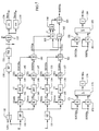
- FIG. 1 schematically shows a three-phase electric power network N1 with the phases A, B and C, which is connected via a transformer T and converter SCR to a d.c. power network N2 with the two lines L1, L2.
- the electric fundamental frequency of the network N1 is designated f.
- the transformer windings may in a known manner be connected into Y-Y and Y- ⁇ patterns for the case where the converter is designed as a 12-pulse connection.
- a plant component 4A is connected by one of its terminals 41A to the phase A in the network N1 and by its other terminal 42A to the ground G.
- Plant components 4B and 4C of the same composition as 4A are connected in a similar manner between phase B and ground and between phase C and ground by means of terminals 41B, 42B and 41C, 42C, respectively.
- One plant component 4D is connected between the lines L1 and L2 in the network N2 by means of terminals 41D and 42D.
- the line L2 is connected to the ground G.
- the plant component 4A comprises a tunable filter according to Figure 1B.
- the filter comprises a main capacitor C0, a main reactor L0 and three branches 1, 2, 3.
- the branch 1 comprises a reactor L1, the branch 2 a reactor L2 series connected to a capacitor C2, and the branch 3 a capacitor C3.
- the voltage U A across the filter is measured by means of a voltage-measuring member 7A, which delivers a signal U proportional to U A
- the current I A through the filter is measured by means of a current-measuring member 8A, which delivers a signal I proportional to I A .
- the current I A comprises components I Af1 , I Af2 , I Af3 and that the voltage U A comprises components U Af1 , U Af2 , U Af3 of the frequencies f1, f2 and f3 respectively, whereby the tuning of the three branches results in at least the main part of the component I Af1 flowing through the branch 1, at least the main part of the component I Af2 flowing through the branch 2, and at least the main part of the component I Af3 flowing through the branch 3.
- a tuning unit TU1, TU2, TU3 is connected between the respective branch and ground.
- the signals U and I are supplied to the tuning units TU1, TU2 and TU3.
- FIG. 2A shows an embodiment of the tuning unit TU1. It comprises a reactor L11 and four capacitors C11 ⁇ C14. The number of capacitors which are connected in series with the reactor L11 may be controlled by means of the switching members S12 ⁇ S14, shown in Figure 2A as mechanical contacts. The capacitance values are preferably chosen such that the impedance of the tuning unit has its minimum when half the number of capacitor elements are connected to the reactor L11.
- the signals U and I are supplied to a detector 10, which is adapted to generate a state signal SUITG1 in dependence on the phase difference between the voltage component U Af1 and the current component I Af1 .
- the signal SUITG1 is supplied to a control unit 11 adapted, in dependence on the signal SUITG1, to activate the switching members S12 - S14 L11 such that the number of capacitors connected in series with the reactor L11 is increased or reduced in such a way that the signal SUITG1, that is, the phase difference between the voltage component U Af1 and the current component I Af1 , is automatically brought in a direction towards the value zero.
- FIG. 2B shows another embodiment of the tuning unit TU1.
- a capacitor C11 is connected in series with two reactors L11 and L12 connected in parallel.
- the effective impedance for the reactor L11 can be varied by means of variation of the control angle for firing pulses FP1, FP2, which are applied, with the frequency f1, to two antilparallel-connected thyristors T11, T12 in series with the reactor L11.
- the firing pulses are generated by a control pulse member 12 in dependence on the state signal SUITG1 in such a way that the phase difference between the voltage component U Af1 and the current component I Af1 is automatically brought in a direction towards the value zero.
- the tuning units TU2 and TU3 are arranged in a similar manner to TU1 but with the difference that their respective state signals SUITG2 and SUITG3 are generated in dependence on the phase difference between the voltage component U Af2 and the current component I Af2 , respectively, in dependence on the phase difference between the voltage component U Af3 and the current component I Af3 .
- the plant component 4D comprises a tunable filter according to Figure 1C.
- the filter comprises a capacitor C14, a reactor L14 and a resistor R14 in series with a tuning unit TU4.
- the voltage U D across the filter is measured by means of a voltage-measuring member 7D which delivers a signal U proportional to U D
- the current I D through the filter by means of a current-measuring member 8D which delivers a signal I proportional to I D .
- the signals U and I and a signal UN1 the function of which will be described in greater detail below, are applied to the tuning unit TU4.
- the tuning unit TU4 is arranged in a manner similar to TU1 but with the difference that its state signal SUITG14 is generated in dependence on the phase difference between a voltage component U Af4 and a current component I Af4 .
- the voltage-sensing member 7D may in this case be advantageously arranged to sense only a.c. voltage components of the voltage between the d.c. lines.
- the plant component 4A may also comprise or consist of a capacitor bank CB according to Figure 1D.
- the voltage U A across the capacitor bank is measured by means of a voltage-measuring member 7C which delivers a signal U proportional to U A
- the current I AC through the bank is measured by means a current-measuring member 8C which delivers a signal I proportional to I AC .
- the signals U and I are supplied to a detector and alarm unit AL.
- Figure 3 shows in the form of a block diagram a method for determining the phase difference and the amplitude according to the invention.
- a signal selected in a selector 22 is supplied to a bandpass filter 131 tuned to the fundamental frequency f of the power network N1.
- the above-mentioned signal UN1 is selected, which represents a value of a voltage or current sensed in the power network N1.
- the signal U is selected.
- the selection is suitably performed such that one of the signals U and UN1 is connected to means for carrying out the method, whereby the selector 22 symbolizes the selection of connected voltage.
- a time-measuring circuit 132 senses the output signal from the bandpass filter and delivers a value T representing the period of the fundamental frequency.
- a quotient generator 133 a quotient T/n is formed between the value T and a number n, where n is a positive integer which is the ordinal number of a selected tone in the power network.
- n is a positive integer which is the ordinal number of a selected tone in the power network.
- the quotient T/n is supplied to a sine generator 134 adapted to generate a sine signal Snsin of an angular frequency n*2 ⁇ t/T , that is, corresponding to the product of the ordinal number of the selected tone and the fundamental frequency associated with the power network, and a cosine generator 135 adapted to generate a cosine signal Sncos of an angular frequency of n*2 ⁇ t/T .
- the signal U is also supplied to a highpass filter 141, which is preferably adapted to block components of U of frequencies lower than the frequency n/T.
- the output signal from the high-pass filter is supplied to a multiplier 142 for multiplication by the signal Snsin as well as to a multiplier 143 for multiplication by the signal Sncos.
- the result R1 from the multiplier 142 is supplied to an integrator 144, adapted to perform an integration over time for a period equal to the period T of the fundamental frequency, and the result of the integration is supplied to a quotient generator 145, in which it is divided by T/2.
- the result R2 from the multiplier 143 is supplied to an integrator 146, adapted to perform an integration over time for a period equal to the period T of the fundamental frequency, and the result of the integration is supplied to a quotient generator 147, in which it is divided by T/2.
- the signal I is supplied to a highpass filter 151, which is preferably adapted to block components of I of frequencies lower than the frequency n/T, and is thereafter treated in a manner analogous to that described above for the signal U in a multiplier 152 for multiplication by the signal Snsin, which provides the result R3, and a multiplier 153 for multiplication by the signal Sncos, which provides the result R4, integrators 154 and 156 and quotient generators 155 and 157.
- a highpass filter 151 which is preferably adapted to block components of I of frequencies lower than the frequency n/T, and is thereafter treated in a manner analogous to that described above for the signal U in a multiplier 152 for multiplication by the signal Snsin, which provides the result R3, and a multiplier 153 for multiplication by the signal Sncos, which provides the result R4, integrators 154 and 156 and quotient generators 155 and 157.
- SITGn is subtracted from SUTGn in a summator 162 and SUTGn is multiplied by SITGn in a multiplier 163 whereafter the product is added to the number ONE in a summator 164.
- the result SUITGn is formed as the quotient between the result from the summator 162 and the summator 163.
- the signal SUITGn may, after suitable signal adaptation, advantageously be supplied to a control unit 11 or a control pulse member 12 as described in connection with Figures 2A and 2B in that it is then possible to utilize the property of the tangent function to provide a high amplification at large phase differences and an amplification, decreasing with the phase difference, in the closed-loop control system which the system according to Figures 1-2 constitutes.
- arctg(SUITGn) which is a direct measure of the phase difference ( ⁇ un - ⁇ In ) can be formed and, after suitable signal adaptation and signal processing comprising, for example, an integrating function, be supplied to the control unit 11 or the control pulse member 12.
- SUn is obtained as a result, which, as realized from equations (4a) and (4b) and known trigonometric relationships, is a value of the amplitude U n for that component of the signal U which has the frequency n*2 ⁇ t/T .
- a memory member which is arranged, for example, in the control unit 11 and in the control pulse member 12, respectively, and which is designated 21 in Figures 2A and 2B, is updated, continuously or periodically, with the current value of SUITGn.
- the switching member S12-S14 is activated and the firing pulses FP1 and FP2 are generated, respectively, in dependence on the value of the signal SUITGn stored in the memory.
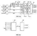
- Figure 4A shows in the form of a block diagram a method for monitoring faults in three single-phase filters connected to a three-phase network N with the phases A, B, C, for example a fault in one part of a capacitive impedance element in a tunable filter.
- Signals SUITGn are formed for each one of the filters and the value associated with the respective phase is designated SUITGnA, SUITGnB, SUITGnC.
- deviation values SEA, SEB and SEC are formed by signal processing in adaptation units 191A, 191B, 191C, which comprise an integrating function.
- the deviation values are added in a summator 192 and the result of the summation is divided by number three in a quotient generator 193, the output signal of which thus forms a mean value of the deviation values.
- Each one of these deviation values along with the mentioned mean value are supplied to an alarm unit 194, in which each of the deviation values are compared in summators 195A, 195B, 195C with their mean value.
- the differences are compared in comparison members 196A, 196B, 196C with a predetermined value.
- the signals SUITGnA, SUITGnB and SUITGnC, which as described above are supplied to control units 11 or control pulse members 12 in the tuning units of the respective filters, achieve, by their function, a minimisation of the respective phase different.
- the corresponding adaptation unit 191A, 191B, 191C by its integrating function, controlling the deviation value SEA, SEB, SEC to a value deviating from the other values.
- a signal is delivered to an alarm member 197 which forwards an alarm AA, AB, AC, for example to an operator panel or to an overriding monitoring system in the plant.
- the comparison member 196A, 196B, 196C may, in a manner not shown in the figure, be doubled with an additional comparison level which, via the alarm member, delivers signals TA, TB, TC for disconnecting the corresponding filters from the power network.
- Figure 4B shows in the form of a block diagram a method for monitoring a single-phase plant component, which can be used to advantage when monitoring non-tunable filters and capacitor banks.
- the values SUn, SIn, formed according to the above, of the amplitude U n and of the amplitude I n , respectively, for that component of the signals U and I which has the frequency n*2 ⁇ t/T are supplied to a calculating unit 201. Furthermore, there are supplied to this calculating unit known values R and L of the resistance and inductance of the monitored plant component as well as a value of the period T/n of the selected tone.
- a calculation of the impedance X n of the plant component at the frequency n*2 ⁇ t/T is performed as where, in equation (7), R denotes the resistance of the plant component, X C the capacitive reactance thereof and X L the inductive reactance thereof. From this, the capacitance C of the capacitive element can be calculated when R, L and T/n are known.
- the value of the inductance L may be derived from the relationship between the inductance value L and the state signal SUITGn, or a signal dependent thereon, which relationship is given by the dimensioning of the system.
- the alarm unit may forward an alarm AC, for example to an operator panel or to an overriding monitoring system in the plant and/or, at a certain level of the deviation, a signal TC for disconnecting the plant component from the power network.
- the method illustrated in Figure 4B may be applied to plant components in each one of the phases.
- the method illustrated in Figure 4A may also be applied for the case where several plant components have been connected to the same phase or line in the power network.
- the integration which is performed in the integrators 144, 146, 154, 156 may also be extended to comprise a plurality of the periods T of the fundamental frequency, in which case the magnitude of the divisor in the quotient generators 145, 147, 155, 157 may be adapted to the selected number of periods.
- voltage may instead, where applicable, be measured across a component in the plant component which is suitable for the purpose.
- the period T may, of course, also, within the inventive concept, be determined as the inverse of the measured value of the frequency in the power network N1.
- the invention may, in applicable parts, be implemented as calculations carried out in a computer or, alternatively, be performed in hard-wired circuits operating according to analog and/or digital technique.
Abstract
Description
- The invention relates to a method for monitoring and control of a component connected to an electric power network according to the precharacterising part of
claim 1. Such a component may, for example, be a filter arranged in a converter plant for high-voltage direct current for filtering harmonics or a capacitor bank for generating reactive power. - A converter connected to an a.c. network, for example a converter included in a converter plant for high-voltage direct current, generates, by its principle of operation, harmonic currents on its a.c. side and harmonic voltages on its d.c. voltage side. In this context, in principle, only harmonics to the fundamental frequency of the a.c. network of the orders


- To reduce the stresses originating from the harmonics on components included in the power network, and to fulfil the requirements made on the effect on the network and telecommunication disturbances, shunt-connected filters are therefore generally installed to limit the propagation of the disturbances in the power network. Harmonics of a lower order, for example those which correspond to k = 1 and for 6-pulse converters also k = 2, are generally filtered through filters tuned to these harmonics whereas harmonics of a higher order may be filtered through a high-pass filter. The filters are composed of passive components, and during the dimensioning it is also taken into consideration that the filters on the a.c. side are to serve as members for generating reactive power. In general, however, the requirements for generation of reactive power in a converter plant for high-voltage direct power result in the need to install one or more further high-voltage capacitor banks on the a.c. side. In certain cases, it may be necessary to install tuned filters and high-pass filters also on the d.c. voltage side of the converter. In a converter plant for high-voltage direct current, these filters and the capacitor banks constitute plant components which essentially influence the function, volume and cost of the plant.
- The tuned filters are generally designed as series-resonance circuits, comprising capacitive, inductive and sometimes also resistive impedance elements, tuned such that, at one or more of the harmonic frequencies expected in the power network, they are to exhibit a purely resistive impedance (resonance frequency condition).
- In narrow-band filters also a small change of the reactance of an impedance element included in the filter may cause a considerable deterioration of the function of the filter. Such a change may, for example, be caused by a fault in one part of a capacitive impedance element. A known method for monitoring this type of fault is to sense a voltage occurring in the filter and a current flowing therethrough and to form the phase difference between the components of the voltage and the current of a frequency selected by means of a bandpass filter, corresponding to the harmonic or one of the harmonics to which the filter is tuned. This phase difference shall be zero when the filter is correctly tuned. A state signal formed in dependence on the phase difference is supplied to an alarm unit to release a fault indicating alarm if the phase difference exceeds a predetermined value.
- Variations in network frequency and drift in component values, the latter caused by, for example, temperature variations or aging, however, mean that an exact tuning generally cannot be maintained although no true faults occur in the filter. It has therefore been proposed to provide the filters with tuning units which allow an adjustment of the resonance frequency or frequencies of the filter via a control member which influences the reactive impedance or impedances of the filter. One known method in this connection is to form a state signal in the manner mentioned above, which is supplied to the control member for the purpose of influencing the reactive impedance of the filter such that the phase difference is minimized in magnitude. The tuning units may, for example, comprise a switchable capacitor bank or a reactor which is controllable by means of a semiconductor connection. A problem in this context is that conventional methods for phase angle measurement, which are based on measurement of the difference in time between two signals whose frequencies are known only approximately, are very sensitive to frequency deviations. This means that the methods mentioned are less suitable for use in filters with very narrow bands.
- To detect a fault in a capacitor bank, the present capacitance thereof can be directly calculated by means of Ohm's law from known amplitude values of current and voltage and be compared with the nominal capacitance value of the capacitor bank. To obtain sufficient sensitivity, however, this method requires that the amplitude values mentioned can be determined with high accuracy.
- The invention aims at developing a method for monitoring and control of a plant component connected to an electric power network which method, for a voltage occurring in the plant component and a current flowing through the plant component, results in a high accuracy in determining the phase difference between the components of the voltage and the current of a selected tone in the power network, and in determining the amplitude of these components. This would make possible a very accurate tuning of tuneable filters and a monitoring with high sensitivity of capacitor banks.
- To achieve this aim the invention suggests a method for monitoring and control of a component connected to an electric power network according to the introductory part of
claim 1, which is characterized by the features of the characterizing part ofclaim 1. - Further developments of the invention are characterized by the features of the additional claims.
- By a tone in the power network is meant in this context a frequency equal to the fundamental frequency associated with the power network, or an integer multiple of this frequency, the fundamental frequency being of the order n = 1. For an a.c. network, fundamental frequency means the system frequency of the network, usually 50 or 60 Hz. For, for example, a d.c. network for transmission of high-voltage direct current, fundamental frequency means the system frequency for the a.c. network which, via the converter, is connected to the d.c. network.
- According to the invention products are formed between a voltage occurring in the plant component and a current flowing therethrough, respectively, sine and cosine signals are formed, the frequencies of which are equal to the product of the order of the selected tone and the fundamental frequency associated with the power network, the products are integrated over time, and the above-mentioned phase difference and amplitude values are determined by quotient generation, multiplication, and summing of the integrated products.
- By way of example, the invention will now be described in greater detail with reference to the accompanying drawings showing in
- Figure 1A
- an a.c. network which is connected to a d.c. network via a converter, and filters and/or capacitor banks connected to the network in a known manner,
- Figures 1B-1C
- known embodiments of tunable filters,
- Figure 1D
- a capacitor bank with a monitoring unit,
- Figures 2A-2B
- known embodiments of tuning units,
- Figure 3
- in the form of a block diagram a method for determining the phase difference and the amplitude according to the invention,
- Figure 4A
- in the form of a block diagram a method for monitoring three single-phase filters connected to a three-phase network, and
- Figure 4B
- in the form of a block diagram a method for monitoring a single-phase filter or a capacitor bank.
- Figure 1 schematically shows a three-phase electric power network N1 with the phases A, B and C, which is connected via a transformer T and converter SCR to a d.c. power network N2 with the two lines L1, L2. The electric fundamental frequency of the network N1 is designated f. The transformer windings may in a known manner be connected into Y-Y and Y-Δ patterns for the case where the converter is designed as a 12-pulse connection. A
plant component 4A is connected by one of itsterminals 41A to the phase A in the network N1 and by itsother terminal 42A to the groundG. Plant components 4B and 4C of the same composition as 4A are connected in a similar manner between phase B and ground and between phase C and ground by means ofterminals plant component 4D is connected between the lines L1 and L2 in the network N2 by means ofterminals - The
plant component 4A comprises a tunable filter according to Figure 1B. The filter comprises a main capacitor C₀, a main reactor L₀ and threebranches branch 1 comprises a reactor L₁, the branch 2 a reactor L₂ series connected to a capacitor C₂, and the branch 3 a capacitor C₃. By means of suitable choices of inductance values and capacitance values, respectively, for the reactors and capacitors included in the three branches, the filter may be tuned to three separate frequencies


member 7A, which delivers a signal U proportional to UA, and the current IA through the filter is measured by means of a current-measuringmember 8A, which delivers a signal I proportional to IA. It is assumed that the current IA comprises components IAf1, IAf2, IAf3 and that the voltage UA comprises components UAf1, UAf2, UAf3 of the frequencies f₁, f₂ and f₃ respectively, whereby the tuning of the three branches results in at least the main part of the component IAf1 flowing through thebranch 1, at least the main part of the component IAf2 flowing through thebranch 2, and at least the main part of the component IAf3 flowing through thebranch 3. For the purpose of maintaining a correct tuning of the respective branch in connection with drift a network frequency and/or component values, in series with each branch a tuning unit TU1, TU2, TU3 is connected between the respective branch and ground. The signals U and I are supplied to the tuning units TU1, TU2 and TU3. - Figure 2A shows an embodiment of the tuning unit TU1. It comprises a reactor L₁₁ and four capacitors C₁₁₋C₁₄. The number of capacitors which are connected in series with the reactor L₁₁ may be controlled by means of the switching members S₁₂₋S₁₄, shown in Figure 2A as mechanical contacts. The capacitance values are preferably chosen such that the impedance of the tuning unit has its minimum when half the number of capacitor elements are connected to the reactor L₁₁. The signals U and I are supplied to a
detector 10, which is adapted to generate a state signal SUITG1 in dependence on the phase difference between the voltage component UAf1 and the current component IAf1. The signal SUITG1 is supplied to acontrol unit 11 adapted, in dependence on the signal SUITG1, to activate the switching members S₁₂ - S₁₄ L₁₁ such that the number of capacitors connected in series with the reactor L₁₁ is increased or reduced in such a way that the signal SUITG1, that is, the phase difference between the voltage component UAf1 and the current component IAf1, is automatically brought in a direction towards the value zero. - Figure 2B shows another embodiment of the tuning unit TU1. A capacitor C₁₁ is connected in series with two reactors L₁₁ and L₁₂ connected in parallel. The effective impedance for the reactor L₁₁ can be varied by means of variation of the control angle for firing pulses FP1, FP2, which are applied, with the frequency f₁, to two antilparallel-connected thyristors T11, T12 in series with the reactor L₁₁. The firing pulses are generated by a
control pulse member 12 in dependence on the state signal SUITG1 in such a way that the phase difference between the voltage component UAf1 and the current component IAf1 is automatically brought in a direction towards the value zero. - The tuning units TU2 and TU3 are arranged in a similar manner to TU1 but with the difference that their respective state signals SUITG2 and SUITG3 are generated in dependence on the phase difference between the voltage component UAf2 and the current component IAf2, respectively, in dependence on the phase difference between the voltage component UAf3 and the current component IAf3.
- The
plant component 4D comprises a tunable filter according to Figure 1C. The filter comprises a capacitor C14, a reactor L₁₄ and a resistor R₁₄ in series with a tuning unit TU4. By means of suitable choices of inductance and capacitance values of the reactor and of the capacitor, the filter can be tuned to a frequency
parts 4A-4C, the voltage UD across the filter is measured by means of a voltage-measuringmember 7D which delivers a signal U proportional to UD, and the current ID through the filter by means of a current-measuringmember 8D which delivers a signal I proportional to ID. The signals U and I and a signal UN1, the function of which will be described in greater detail below, are applied to the tuning unit TU4. - The tuning unit TU4 is arranged in a manner similar to TU1 but with the difference that its state signal SUITG14 is generated in dependence on the phase difference between a voltage component UAf4 and a current component IAf4. The voltage-sensing
member 7D may in this case be advantageously arranged to sense only a.c. voltage components of the voltage between the d.c. lines. - The
plant component 4A may also comprise or consist of a capacitor bank CB according to Figure 1D. In similar manner to what has been described above, the voltage UA across the capacitor bank is measured by means of a voltage-measuringmember 7C which delivers a signal U proportional to UA, and the current IAC through the bank is measured by means a current-measuringmember 8C which delivers a signal I proportional to IAC. The signals U and I are supplied to a detector and alarm unit AL. - The method according to the invention is illustrated in the following description through block diagrams, the results of the operations symbolized by the blocks also being designated by a signal or a value.
- Figure 3 shows in the form of a block diagram a method for determining the phase difference and the amplitude according to the invention. A signal selected in a
selector 22 is supplied to abandpass filter 131 tuned to the fundamental frequency f of the power network N1. In the event that the method is applied to a filter connected to a d.c. network as shown for theplant component 4D in Figure 1A, the above-mentioned signal UN1 is selected, which represents a value of a voltage or current sensed in the power network N1. In the event that the method is applied to a plant component connected to an a.c. network, the signal U is selected. In the implementation of the method, the selection is suitably performed such that one of the signals U and UN1 is connected to means for carrying out the method, whereby theselector 22 symbolizes the selection of connected voltage. A time-measuringcircuit 132 senses the output signal from the bandpass filter and delivers a value T representing the period of the fundamental frequency. In aquotient generator 133, a quotient T/n is formed between the value T and a number n, where n is a positive integer which is the ordinal number of a selected tone in the power network. For, for example, a filter device on the a.c. side of a 12-pulse converter in a plant for high-voltage direct current, the number n may, for example, be selected at n = 11 or n = 13. For a filter device on the d.c. voltage side with the same application, the number n may, for example, be selected at n = 12. The quotient T/n is supplied to asine generator 134 adapted to generate a sine signal Snsin of an angular frequency
cosine generator 135 adapted to generate a cosine signal Sncos of an angular frequency of
- The signal U is also supplied to a
highpass filter 141, which is preferably adapted to block components of U of frequencies lower than the frequency n/T. The output signal from the high-pass filter is supplied to amultiplier 142 for multiplication by the signal Snsin as well as to amultiplier 143 for multiplication by the signal Sncos. The result R1 from themultiplier 142 is supplied to anintegrator 144, adapted to perform an integration over time for a period equal to the period T of the fundamental frequency, and the result of the integration is supplied to aquotient generator 145, in which it is divided by T/2. The result R2 from themultiplier 143 is supplied to anintegrator 146, adapted to perform an integration over time for a period equal to the period T of the fundamental frequency, and the result of the integration is supplied to aquotient generator 147, in which it is divided by T/2. - It is now assumed that the signal U can be expressed as a Fourier series

The signal S' is formed by multiplying U(t) according to equation (1) by the factor
natural number 

After development of the trigonometric term in equation (1) and insertion into equations (2a) and (2b) as well as further use of known trigonometric relationships and trigonometric integrals, the following is obtained


A direct comparison with Figure 3 and the description in connection therewith shows that the result from thequotient generator 145, designated SUCOSn, is

and the result from thequotient generator 147, designated SUSINn, is

where thus Un designates the amplitude and φun the phase angle for the component of the signal U which has the frequency
- The signal I is supplied to a
highpass filter 151, which is preferably adapted to block components of I of frequencies lower than the frequency n/T, and is thereafter treated in a manner analogous to that described above for the signal U in amultiplier 152 for multiplication by the signal Snsin, which provides the result R3, and amultiplier 153 for multiplication by the signal Sncos, which provides the result R4,integrators quotient generators quotient generator 155, designated SICOSn, is
and the result from thequotient generator 157, designated SISINn, is

where thus In designates the amplitude and φIn the phase angle for the component of the signal I which has the frequency
- The result SUSINn is divided by the result SUCOSn in a
quotient generator 160, which gives the result SUTGn = tgφun and the result SISINn is divided by the result SICOSn in aquotient generator 161, which gives the result SITGn = tgφIn, SITGn is subtracted from SUTGn in asummator 162 and SUTGn is multiplied by SITGn in amultiplier 163 whereafter the product is added to the number ONE in asummator 164. In aquotient generator 165 the result SUITGn is formed as the quotient between the result from thesummator 162 and thesummator 163. - A comparison with the known relationship


where φun is the phase angle for the component of the signal U which has the frequency

- The signal SUITGn may, after suitable signal adaptation, advantageously be supplied to a
control unit 11 or acontrol pulse member 12 as described in connection with Figures 2A and 2B in that it is then possible to utilize the property of the tangent function to provide a high amplification at large phase differences and an amplification, decreasing with the phase difference, in the closed-loop control system which the system according to Figures 1-2 constitutes. - Alternatively, arctg(SUITGn), which is a direct measure of the phase difference (φun-φIn) can be formed and, after suitable signal adaptation and signal processing comprising, for example, an integrating function, be supplied to the
control unit 11 or thecontrol pulse member 12. - By supplying to a
multiplier 171 the result SUCOSn and to amultiplier 172 the result SUSINn and adding the products in asummator 173 and then in a calculatingmember 174 extracting the square root of the sum, SUn is obtained as a result, which, as realized from equations (4a) and (4b) and known trigonometric relationships, is a value of the amplitude Un for that component of the signal U which has the frequency
- An analogous processing of the results SICOSn and SISINn in
multipliers summator 183 and in a calculatingmember 184 provides the result SIn, which, as is analogously realized, is a value of the amplitude In of that component of the signal U which has the frequency
- In an advantageous embodiment of the invention, a memory member which is arranged, for example, in the
control unit 11 and in thecontrol pulse member 12, respectively, and which is designated 21 in Figures 2A and 2B, is updated, continuously or periodically, with the current value of SUITGn. In this case, the switching member S12-S14 is activated and the firing pulses FP1 and FP2 are generated, respectively, in dependence on the value of the signal SUITGn stored in the memory. During a process when the tuning of the filter is changed in a direction towards its ideal value, both the phase difference between current and voltage for the filter, and hence the state signal SUITGn, and the magnitude of the voltage across the filter, and hence the signal US, will proceed towards zero. It is then advantageous to sense the magnitude of the amplitude signal SUn, for example in a comparison circuit arranged at the memory member, and when this magnitude is lower than a selected comparison level, to influence the memory member in some way known per se such that this member, as long a the magnitude of the amplitude signal USn remains lower than the comparison value, retains the value of SUITGn which prevailed when the magnitude of SUn became lower than the comparison level. - Figure 4A shows in the form of a block diagram a method for monitoring faults in three single-phase filters connected to a three-phase network N with the phases A, B, C, for example a fault in one part of a capacitive impedance element in a tunable filter. Signals SUITGn are formed for each one of the filters and the value associated with the respective phase is designated SUITGnA, SUITGnB, SUITGnC. In dependence on these values, deviation values SEA, SEB and SEC are formed by signal processing in
adaptation units summator 192 and the result of the summation is divided by number three in aquotient generator 193, the output signal of which thus forms a mean value of the deviation values. Each one of these deviation values along with the mentioned mean value are supplied to analarm unit 194, in which each of the deviation values are compared insummators comparison members 196A, 196B, 196C with a predetermined value. The signals SUITGnA, SUITGnB and SUITGnC, which as described above are supplied to controlunits 11 orcontrol pulse members 12 in the tuning units of the respective filters, achieve, by their function, a minimisation of the respective phase different. However, in the event that there should be a fault in one component of a filter, an influence should be exerted on those resonance-determining elements of this filter which deviate from the influence on the filters in which there is no fault. This is achieved by thecorresponding adaptation unit alarm member 197 which forwards an alarm AA, AB, AC, for example to an operator panel or to an overriding monitoring system in the plant. Thecomparison member 196A, 196B, 196C may, in a manner not shown in the figure, be doubled with an additional comparison level which, via the alarm member, delivers signals TA, TB, TC for disconnecting the corresponding filters from the power network. - Figure 4B shows in the form of a block diagram a method for monitoring a single-phase plant component, which can be used to advantage when monitoring non-tunable filters and capacitor banks. The values SUn, SIn, formed according to the above, of the amplitude Un and of the amplitude In, respectively, for that component of the signals U and I which has the frequency

unit 201. Furthermore, there are supplied to this calculating unit known values R and L of the resistance and inductance of the monitored plant component as well as a value of the period T/n of the selected tone. In the calculating unit a calculation of the impedance Xn of the plant component at the frequency

where, in equation (7), R denotes the resistance of the plant component, XC the capacitive reactance thereof and XL the inductive reactance thereof. From this, the capacitance C of the capacitive element can be calculated when R, L and T/n are known. In the event that the monitored plant component constitutes a tunable filter, whose reactive impedance is influenced by means of a controllable reactor, the value of the inductance L may be derived from the relationship between the inductance value L and the state signal SUITGn, or a signal dependent thereon, which relationship is given by the dimensioning of the system. In the calculation it is advantageous to correct, in a manner known per se, for the temperature dependence of at least the capacitive element by supplying to the calculating member a value TEMP of the current ambient temperature or another temperature value related to the operating temperature thereof. Further, it is advantageous in this case to utilize, for the calculation of C, the fundamental frequency associated with the power network, that is, to select the tone with the ordinal number corresponding to n = 1. The value of the capacitance C thus calculated is supplied to analarm unit 202 for comparison with a known nominal value. In dependence on the magnitude of the deviation, the alarm unit may forward an alarm AC, for example to an operator panel or to an overriding monitoring system in the plant and/or, at a certain level of the deviation, a signal TC for disconnecting the plant component from the power network. - In multi-phase plants the method illustrated in Figure 4B may be applied to plant components in each one of the phases.
- The method illustrated in Figure 4A may also be applied for the case where several plant components have been connected to the same phase or line in the power network.
- The integration which is performed in the
integrators quotient generators - As an alternative to measuring the total voltage across the plant component in question, voltage may instead, where applicable, be measured across a component in the plant component which is suitable for the purpose.
- The period T may, of course, also, within the inventive concept, be determined as the inverse of the measured value of the frequency in the power network N1.
- While it is advantageous to high-pass filter the signals U and I, this is not necessary to carry out the method according to the invention.
- The invention may, in applicable parts, be implemented as calculations carried out in a computer or, alternatively, be performed in hard-wired circuits operating according to analog and/or digital technique.
Claims (8)
- A method for monitoring and/or controlling of a plant component (4A, 4B, 4C, 4D) connected to an electric power network (N1,N2), for example a tunable filter for filtering harmonics in a converter plant for high-voltage direct current, the reactive impedance of which is influenced via a control member, wherein a voltage (UA, UB, UC, UD) occurring in the plant component and a current (IA, IB, IC, ID, IAC) flowing through the plant component are sensed, the phase difference (φun-φIn) between the components of the voltage and the current of a selected tone in the power network is formed, and a state signal (SUITGn) formed in dependence on the phase difference is supplied to the control member for the purpose of influencing the reactive impedance of the plant component such that said phase difference is minimized in magnitude, characterized in thata) a sine and a cosine signal (Snsin, Sncos) are formed, both of a frequency
 b) a first product (R1) is formed between a sensed value of said voltage and the sine signal, a second product (R2) is formed between a sensed value of said voltage and the cosine signal, a third product (R3) is formed between a sensed value of said current and the sine signal, and a fourth product (R4) is formed between a sensed value of said current and the cosine signal,c) each one of the products is integrated over a time equal to the period (T) for a fundamental frequency (f) associated with the power network, or a multiple of said period, andd) said phase difference is determined by quotient generation, multiplication and summation of the integrated products.
 - A method for monitoring and/or controlling of at least two plant component (4A, 4B, 4C, 4D) connected to an electric power network (N1,N2), for example filters for filtering harmonics in a converter plant for high-voltage direct current, wherein, for each of the plant components, a voltage (UA, UB, UC, UD) occurring in the plant component and a current (IA, IB, IC, ID, IAC) flowing through the plant component are sensed, the phase difference (φun-φIn) between the components of the voltage and the current of a selected tone in the power network is formed, and a state signal (SUITGn) formed in dependence on the phase difference is supplied to an alarm unit, characterized in thata) a sine and a cosine signal are formed, both of a frequency
 b) a first product (R1) is formed between a sensed value of said voltage and the sine signal, a second product (R2) is formed between a sensed value of said voltage and the cosine signal, a third product (R3) is formed between a sensed value of said current and the sine signal, and a fourth product (R4) is formed between a sensed value of said current and the cosine signal,c) each one of the products is integrated over a time equal to the period (T) for a fundamental frequency (f) associated with the power network, or a multiple of said period,d) said phase difference is determined by quotient generation, multiplication and summation of the integrated products, ande) the signal formed in dependence on the phase difference is supplied to the alarm unit for comparison with a signal formed in dependence on phase differences for more than one of the plant components arranged in the power network.
 - A method for monitoring and/or controlling a plant component connected to an electric power network (N1, N2), said component comprising at least one capacitive impedance element (C₁₄, CB), for example a filter for harmonic filtering or a capacitor bank for generating reactive power in a converter plant for high-voltage direct current, wherein a voltage (UA, UB, UC, UD) occurring in the plant component and a current (IA, IB, IC, ID, IAC) flowing through the plant component are sensed, and the amplitude value for the components (SUn, SIn) of the voltage and the current of a selected tone in the power network is formed, characterized in thata) a sine and a cosine signal are formed, both of a frequency
 b) a first product (R1) is formed between a sensed value of said voltage and the sine signal, a second product (R2) is formed between a sensed value of said voltage and the cosine signal, a third product (R3) is formed between a sensed value of said current and the sine signal, and a fourth product (R4) is formed between a sensed value of said current and the cosine signal,c) each one of the products is integrated over a time equal to the period (T) for a fundamental frequency (f) associated with the power network, or a multiple of said period, andd) said amplitude values are determined by quotient generation, multiplication and summation of the integrated productse) the amplitude values, a value of the selected tone or the period (T/n) thereof, a known value of the resistance (R) of the plant component, and a known value of the inductance (L) of the plant component ar supplied to a calculating unit (201) for calculating the capacitance (C) of the capacitive impedance element, andf) the value of the capacitance of the capacitive impedance element is supplied to an alarm unit (202) for comparison with a predetermined reference value.
 - A method according to claim 1 or 2, characterized in that the tangent value (tgφun) of the phase angle for said voltage component and the tangent value (tgφIn) of the phase angle for said current component are formed by quotient generation of the integrated products and that the signal in dependence on the phase difference is formed by summation, multiplication, and quotient generation of said tangent values.
- A method according to claim 2, characterized in that for each one of the plant components, a signal (SEA, SEB, SEC), formed in dependence on the phase difference, is supplied to the alarm unit for comparison with a signal formed in dependence on the mean value of the phase differences for more than one of the plant components arranged in the power network.
- A method according to claim 3, characterized in that the amplitude values are formed by squaring, summation and root extraction of the integrated products.
- A method according to claim 6, characterized in that the calculating unit is supplied with a value (TEMP) related to the operating temperature of at least the capacitive impedance element, for example the operating temperature of the plant component, to be included as a parameter in the calculation of the capacitance of the capacitive impedance element.
- A method according to any of the preceding claims, characterized in that the selected tone is determined as the product of a selected integer (n) and a sensed value of the fundamental frequency (f or 1/T) associated with the power network.
Applications Claiming Priority (2)
| Application Number | Priority Date | Filing Date | Title |
|---|---|---|---|
| SE9303050 | 1993-09-20 | ||
| SE9303050A SE501786C2 (en) | 1993-09-20 | 1993-09-20 | A method for monitoring and controlling a plant part connected to an electrical power grid |
Publications (2)
| Publication Number | Publication Date |
|---|---|
| EP0645866A1 true EP0645866A1 (en) | 1995-03-29 |
| EP0645866B1 EP0645866B1 (en) | 1998-11-25 |
Family
ID=20391145
Family Applications (1)
| Application Number | Title | Priority Date | Filing Date |
|---|---|---|---|
| EP94114665A Expired - Lifetime EP0645866B1 (en) | 1993-09-20 | 1994-09-17 | Method for monitoring and control of a component connected to an electric power network |
Country Status (6)
| Country | Link |
|---|---|
| US (1) | US5568042A (en) |
| EP (1) | EP0645866B1 (en) |
| JP (1) | JPH07177662A (en) |
| CA (1) | CA2132392C (en) |
| DE (1) | DE69414803T2 (en) |
| SE (1) | SE501786C2 (en) |
Cited By (11)
| Publication number | Priority date | Publication date | Assignee | Title |
|---|---|---|---|---|
| FR2767610A1 (en) * | 1997-08-21 | 1999-02-26 | Schneider Electric Sa | Startup switch for microwave oven control system |
| US6441712B2 (en) | 2000-03-01 | 2002-08-27 | Alstom | Tuned filters for electric power systems |
| EP1318588A2 (en) * | 2001-11-28 | 2003-06-11 | Abb Ab | A method and a device for compensation of the comsumption of reactive power by an industrial load |
| EP1585206A1 (en) * | 2004-03-15 | 2005-10-12 | Icar S.p.A. - Industria Condensatori | Rephasing assembly for electrical power grids |
| WO2011003435A1 (en) * | 2009-07-06 | 2011-01-13 | Abb Technology Ag | An arrangement and a method for monitoring the status of dc-side reactors in an hvdc transmission |
| EP2299568A1 (en) * | 2009-08-21 | 2011-03-23 | Vestas Wind Systems A/S | System and method for monitoring power filters and detecting power filter failure in a wind turbine electrical generator |
| EP2568587A1 (en) * | 2011-09-06 | 2013-03-13 | Siemens Aktiengesellschaft | Mains filter for a converter and converter with such a mains filter |
| EP2816698A1 (en) * | 2013-06-21 | 2014-12-24 | Hamilton Sundstrand Corporation | Systems and methods for tuning the control of a shunt active power filter over a variable frequency |
| DE102015101766A1 (en) * | 2015-02-06 | 2016-08-11 | Woodward Kempen Gmbh | filter monitoring |
| CN111585269A (en) * | 2020-05-27 | 2020-08-25 | 南方电网科学研究院有限责任公司 | Direct-current filter transformation method of multi-terminal direct-current power transmission system |
| EP3123493B1 (en) * | 2014-03-24 | 2023-01-25 | Advanced Fusion Systems LLC | Improving power factor in ac power system |
Families Citing this family (19)
| Publication number | Priority date | Publication date | Assignee | Title |
|---|---|---|---|---|
| US6202000B1 (en) * | 1997-12-30 | 2001-03-13 | Samsung Electronics Co., Ltd. | Monitoring system for semiconductor device fabrication facility |
| US6121758A (en) * | 1999-06-23 | 2000-09-19 | Daq Electronics, Inc. | Adaptive synchronous capacitor switch controller |
| US6181113B1 (en) | 1999-07-29 | 2001-01-30 | Abb Power T&D Company Inc. | Harmonic resonance control and protection system for switched power factor control capacitor devices |
| JP3946933B2 (en) * | 2000-05-26 | 2007-07-18 | 三菱電機株式会社 | Current detection apparatus and current detection method |
| DE10213845B4 (en) * | 2002-03-27 | 2005-10-20 | Siemens Ag | Arrangement for the electrical power supply of a consumer by means of a two-part transmission path |
| US8564922B1 (en) | 2010-07-22 | 2013-10-22 | Adtran, Inc. | System and method for protecting telecommunications device from power faults |
| US8693679B1 (en) * | 2010-07-22 | 2014-04-08 | Adtran, Inc. | Communications system and associated method for reducing power consumption of a telecommunications device |
| EP2856596B1 (en) | 2012-06-01 | 2016-06-01 | ABB Technology Ltd. | A filter apparatus, a method for filtering harmonics in an electrical power transmission or distribution system, and such a system |
| US20150124358A1 (en) * | 2013-11-01 | 2015-05-07 | Eaton Corporation | Feeder power source providing open feeder detection for a network protector by shifted neutral |
| KR101995721B1 (en) * | 2015-07-30 | 2019-10-01 | 엘에스산전 주식회사 | Power loss measuring system for measuring power loss at harmonic filter included in high voltage direct current(hvdc) ststem and method for measuring power loss thereof |
| JP6864467B2 (en) * | 2016-12-20 | 2021-04-28 | 東芝産業機器システム株式会社 | Single phase inverter |
| JP6867816B2 (en) * | 2017-01-26 | 2021-05-12 | 東芝産業機器システム株式会社 | Converter |
| CN108173257B (en) * | 2018-03-22 | 2024-01-23 | 南方电网科学研究院有限责任公司 | System and method for inhibiting harmonic instability of direct current transmission system |
| CN109164293B (en) * | 2018-07-10 | 2022-06-17 | 深圳市华宝新能源股份有限公司 | Commercial power failure detection method, electronic equipment, storage medium and energy storage system |
| DE102018126742A1 (en) * | 2018-10-26 | 2020-04-30 | Maschinenfabrik Reinhausen Gmbh | Filter device for an energy network, use of a throttle arrangement and method for operating a filter device |
| DE102019101312A1 (en) * | 2019-01-18 | 2020-07-23 | Maschinenfabrik Reinhausen Gmbh | Filter device for an energy network and method for operating a filter device |
| US10686376B1 (en) * | 2019-05-06 | 2020-06-16 | Hamilton Sunstrand Corporation | Method and system for control of tunable passive component based power filters |
| DE102020203319A1 (en) | 2020-03-16 | 2021-09-16 | Volkswagen Aktiengesellschaft | High voltage system |
| EP4350375A1 (en) * | 2022-10-06 | 2024-04-10 | Abb Schweiz Ag | Filter capacitance estimation by resonance frequency determination |
Citations (3)
| Publication number | Priority date | Publication date | Assignee | Title |
|---|---|---|---|---|
| US4680531A (en) * | 1986-05-15 | 1987-07-14 | Bbc Brown, Boveri & Company, Limited | Method for attenuating at least one electric harmonic of the system frequency in a multi-phase alternating-current system |
| US4906860A (en) * | 1987-11-16 | 1990-03-06 | Mitsubishi Denki Kabushiki Kaisha | Control device for active filter |
| EP0519635A2 (en) * | 1991-06-14 | 1992-12-23 | Hitachi, Ltd. | Method and apparatus for controlling the output voltage of an AC electrical system |
Family Cites Families (2)
| Publication number | Priority date | Publication date | Assignee | Title |
|---|---|---|---|---|
| US4811236A (en) * | 1986-11-03 | 1989-03-07 | Westinghouse Electric Corp. | Transmission line voltage detector for static VAR generator |
| US5351181A (en) * | 1993-03-12 | 1994-09-27 | Electric Power Research Institute, Inc. | Low cost active power line conditioner |
-
1993
- 1993-09-20 SE SE9303050A patent/SE501786C2/en not_active IP Right Cessation
-
1994
- 1994-09-15 US US08/305,328 patent/US5568042A/en not_active Expired - Lifetime
- 1994-09-17 DE DE69414803T patent/DE69414803T2/en not_active Expired - Lifetime
- 1994-09-17 EP EP94114665A patent/EP0645866B1/en not_active Expired - Lifetime
- 1994-09-19 CA CA002132392A patent/CA2132392C/en not_active Expired - Lifetime
- 1994-09-19 JP JP6223476A patent/JPH07177662A/en active Pending
Patent Citations (3)
| Publication number | Priority date | Publication date | Assignee | Title |
|---|---|---|---|---|
| US4680531A (en) * | 1986-05-15 | 1987-07-14 | Bbc Brown, Boveri & Company, Limited | Method for attenuating at least one electric harmonic of the system frequency in a multi-phase alternating-current system |
| US4906860A (en) * | 1987-11-16 | 1990-03-06 | Mitsubishi Denki Kabushiki Kaisha | Control device for active filter |
| EP0519635A2 (en) * | 1991-06-14 | 1992-12-23 | Hitachi, Ltd. | Method and apparatus for controlling the output voltage of an AC electrical system |
Non-Patent Citations (1)
| Title |
|---|
| MEANS FOR DETECTING FAULTS IN FILTER CAPACITORS, RESEARCH DISCLOSURE, no. 182, June 1979 (1979-06-01), pages 308 - 309 * |
Cited By (21)
| Publication number | Priority date | Publication date | Assignee | Title |
|---|---|---|---|---|
| FR2767610A1 (en) * | 1997-08-21 | 1999-02-26 | Schneider Electric Sa | Startup switch for microwave oven control system |
| EP0903829A1 (en) * | 1997-08-21 | 1999-03-24 | Schneider Electric Sa | Filter device having a control circuit and electric apparatus using such device |
| US6140866A (en) * | 1997-08-21 | 2000-10-31 | Schneider Electric Sa | Filtering device comprising a control circuit and an electrical apparatus comprising such a device |
| US6441712B2 (en) | 2000-03-01 | 2002-08-27 | Alstom | Tuned filters for electric power systems |
| EP1318588A3 (en) * | 2001-11-28 | 2008-08-13 | Abb Ab | A method and a device for compensation of the comsumption of reactive power by an industrial load |
| EP1318588A2 (en) * | 2001-11-28 | 2003-06-11 | Abb Ab | A method and a device for compensation of the comsumption of reactive power by an industrial load |
| EP1585206A1 (en) * | 2004-03-15 | 2005-10-12 | Icar S.p.A. - Industria Condensatori | Rephasing assembly for electrical power grids |
| WO2011003435A1 (en) * | 2009-07-06 | 2011-01-13 | Abb Technology Ag | An arrangement and a method for monitoring the status of dc-side reactors in an hvdc transmission |
| CN101995529B (en) * | 2009-08-21 | 2015-01-28 | 维斯塔斯风力系统集团公司 | System and method for monitoring power filters and detecting power filter failure in wind turbine electrical generator |
| EP2299568A1 (en) * | 2009-08-21 | 2011-03-23 | Vestas Wind Systems A/S | System and method for monitoring power filters and detecting power filter failure in a wind turbine electrical generator |
| CN101995529A (en) * | 2009-08-21 | 2011-03-30 | 维斯塔斯风力系统集团公司 | System and method for monitoring power filters and detecting power filter failure in wind turbine electrical generator |
| AU2010212454B2 (en) * | 2009-08-21 | 2014-05-22 | Vestas Wind Systems A/S | System and method for monitoring power filters and detecting power filter failure in a wind turbine electrical generator |
| US8898025B2 (en) | 2009-08-21 | 2014-11-25 | Vestas Wind Systems A/S | System and method for monitoring power filters and detecting power filter failure in a wind turbine electrical generator |
| EP2568587A1 (en) * | 2011-09-06 | 2013-03-13 | Siemens Aktiengesellschaft | Mains filter for a converter and converter with such a mains filter |
| EP2816698A1 (en) * | 2013-06-21 | 2014-12-24 | Hamilton Sundstrand Corporation | Systems and methods for tuning the control of a shunt active power filter over a variable frequency |
| US9225172B2 (en) | 2013-06-21 | 2015-12-29 | Hamilton Sundstrand Corporation | Systems and methods for tuning the control of a shunt active power filter over a variable frequency |
| EP3123493B1 (en) * | 2014-03-24 | 2023-01-25 | Advanced Fusion Systems LLC | Improving power factor in ac power system |
| DE102015101766A1 (en) * | 2015-02-06 | 2016-08-11 | Woodward Kempen Gmbh | filter monitoring |
| US10090680B2 (en) | 2015-02-06 | 2018-10-02 | Woodward Kempen Gmbh | High accuracy mains filter monitoring for a multi-phase power system |
| CN111585269A (en) * | 2020-05-27 | 2020-08-25 | 南方电网科学研究院有限责任公司 | Direct-current filter transformation method of multi-terminal direct-current power transmission system |
| CN111585269B (en) * | 2020-05-27 | 2021-07-30 | 南方电网科学研究院有限责任公司 | Direct-current filter transformation method of multi-terminal direct-current power transmission system |
Also Published As
| Publication number | Publication date |
|---|---|
| CA2132392C (en) | 1999-05-25 |
| SE9303050D0 (en) | 1993-09-20 |
| SE9303050L (en) | 1995-03-21 |
| DE69414803D1 (en) | 1999-01-07 |
| CA2132392A1 (en) | 1995-03-21 |
| DE69414803T2 (en) | 1999-07-08 |
| US5568042A (en) | 1996-10-22 |
| JPH07177662A (en) | 1995-07-14 |
| EP0645866B1 (en) | 1998-11-25 |
| SE501786C2 (en) | 1995-05-15 |
Similar Documents
| Publication | Publication Date | Title |
|---|---|---|
| EP0645866B1 (en) | Method for monitoring and control of a component connected to an electric power network | |
| US4104687A (en) | Device for detecting unbalanced conditions in a polyphase equipment bank | |
| US5383084A (en) | Circuit analyzing system | |
| CN1786726B (en) | System and method of locating ground fault in electrical power distribution system | |
| US4300182A (en) | Metering and protection system for an A.C. power system | |
| US5066920A (en) | Correction procedure of the phase difference introduced by a zero sequence toroid of leakage current and isolation monitor this procedure | |
| WO1994009377A1 (en) | A method and a device for determining the distance from a measuring station to a fault on a transmission line | |
| US4638242A (en) | Method and device for measuring insulation deterioration of electric line | |
| US4261038A (en) | Protection of electrical power supply systems | |
| US4667152A (en) | Method of and system for determining locations of sources of harmonics in a power distribution network | |
| US6313614B1 (en) | Method and a device for controlling a secondary voltage in a transformer device connected to a power network and comprising an on-load tap-changer | |
| US6046895A (en) | Distance protection method | |
| Hosono et al. | Suppression and measurement of arc furnace flicker with a large static var compensator | |
| EP0467675A2 (en) | Programmable inverse time delay circuit | |
| EP0107332B1 (en) | Power line filters | |
| Czarnecki | Effect of minor harmonics on the performance of resonant harmonic filters in distribution systems | |
| US4419660A (en) | Electric filter equipment | |
| EP0632559B1 (en) | Negative-sequence time-overcurrent relay | |
| CA2435367C (en) | Device and method for protection against overcurrents in an electrical energy distribution cabinet | |
| SU1069054A1 (en) | Device for protective de-energization in system with solidly earthed neutral | |
| CA1085449A (en) | Filter excitation circuitry | |
| RU2014702C1 (en) | Gear for protection of synchronous generator against fault to ground in one point of excitation circuit | |
| SU1488918A1 (en) | Filter | |
| SU1053218A1 (en) | Upper-harmonic filter control device | |
| Cotten et al. | Analysis of harmonic pollution on power distribution systems |
Legal Events
| Date | Code | Title | Description |
|---|---|---|---|
| PUAI | Public reference made under article 153(3) epc to a published international application that has entered the european phase |
Free format text: ORIGINAL CODE: 0009012 |
|
| AK | Designated contracting states |
Kind code of ref document: A1 Designated state(s): DE FR GB IT |
|
| 17P | Request for examination filed |
Effective date: 19950428 |
|
| GRAG | Despatch of communication of intention to grant |
Free format text: ORIGINAL CODE: EPIDOS AGRA |
|
| 17Q | First examination report despatched |
Effective date: 19971017 |
|
| GRAG | Despatch of communication of intention to grant |
Free format text: ORIGINAL CODE: EPIDOS AGRA |
|
| GRAH | Despatch of communication of intention to grant a patent |
Free format text: ORIGINAL CODE: EPIDOS IGRA |
|
| GRAH | Despatch of communication of intention to grant a patent |
Free format text: ORIGINAL CODE: EPIDOS IGRA |
|
| GRAA | (expected) grant |
Free format text: ORIGINAL CODE: 0009210 |
|
| AK | Designated contracting states |
Kind code of ref document: B1 Designated state(s): DE FR GB IT |
|
| REF | Corresponds to: |
Ref document number: 69414803 Country of ref document: DE Date of ref document: 19990107 |
|
| ITF | It: translation for a ep patent filed |
Owner name: JACOBACCI & PERANI S.P.A. |
|
| ET | Fr: translation filed | ||
| PLBE | No opposition filed within time limit |
Free format text: ORIGINAL CODE: 0009261 |
|
| STAA | Information on the status of an ep patent application or granted ep patent |
Free format text: STATUS: NO OPPOSITION FILED WITHIN TIME LIMIT |
|
| 26N | No opposition filed | ||
| REG | Reference to a national code |
Ref country code: GB Ref legal event code: IF02 |
|
| PGFP | Annual fee paid to national office [announced via postgrant information from national office to epo] |
Ref country code: DE Payment date: 20130911 Year of fee payment: 20 |
|
| PGFP | Annual fee paid to national office [announced via postgrant information from national office to epo] |
Ref country code: GB Payment date: 20130911 Year of fee payment: 20 Ref country code: FR Payment date: 20130910 Year of fee payment: 20 |
|
| PGFP | Annual fee paid to national office [announced via postgrant information from national office to epo] |
Ref country code: IT Payment date: 20130910 Year of fee payment: 20 |
|
| REG | Reference to a national code |
Ref country code: DE Ref legal event code: R082 Ref document number: 69414803 Country of ref document: DE Representative=s name: WEICKMANN & WEICKMANN, DE Ref country code: DE Ref legal event code: R082 Ref document number: 69414803 Country of ref document: DE Representative=s name: HANSMANN & VOGESER, DE |
|
| REG | Reference to a national code |
Ref country code: DE Ref legal event code: R071 Ref document number: 69414803 Country of ref document: DE |
|
| REG | Reference to a national code |
Ref country code: DE Ref legal event code: R071 Ref document number: 69414803 Country of ref document: DE |
|
| REG | Reference to a national code |
Ref country code: GB Ref legal event code: PE20 Expiry date: 20140916 |
|
| PG25 | Lapsed in a contracting state [announced via postgrant information from national office to epo] |
Ref country code: DE Free format text: LAPSE BECAUSE OF EXPIRATION OF PROTECTION Effective date: 20140918 |
|
| PG25 | Lapsed in a contracting state [announced via postgrant information from national office to epo] |
Ref country code: GB Free format text: LAPSE BECAUSE OF EXPIRATION OF PROTECTION Effective date: 20140916 |