EP0647985A2 - Coaxial connector comprising coaxial connector plug connected to coaxial cable and coaxial connector receptacle connected to printed circuit board - Google Patents
Coaxial connector comprising coaxial connector plug connected to coaxial cable and coaxial connector receptacle connected to printed circuit board Download PDFInfo
- Publication number
- EP0647985A2 EP0647985A2 EP94115752A EP94115752A EP0647985A2 EP 0647985 A2 EP0647985 A2 EP 0647985A2 EP 94115752 A EP94115752 A EP 94115752A EP 94115752 A EP94115752 A EP 94115752A EP 0647985 A2 EP0647985 A2 EP 0647985A2
- Authority
- EP
- European Patent Office
- Prior art keywords
- contact
- press
- plug
- coaxial connector
- receptacle
- Prior art date
- Legal status (The legal status is an assumption and is not a legal conclusion. Google has not performed a legal analysis and makes no representation as to the accuracy of the status listed.)
- Granted
Links
Images


Classifications
-
- H—ELECTRICITY
- H01—ELECTRIC ELEMENTS
- H01R—ELECTRICALLY-CONDUCTIVE CONNECTIONS; STRUCTURAL ASSOCIATIONS OF A PLURALITY OF MUTUALLY-INSULATED ELECTRICAL CONNECTING ELEMENTS; COUPLING DEVICES; CURRENT COLLECTORS
- H01R24/00—Two-part coupling devices, or either of their cooperating parts, characterised by their overall structure
- H01R24/38—Two-part coupling devices, or either of their cooperating parts, characterised by their overall structure having concentrically or coaxially arranged contacts
- H01R24/40—Two-part coupling devices, or either of their cooperating parts, characterised by their overall structure having concentrically or coaxially arranged contacts specially adapted for high frequency
- H01R24/50—Two-part coupling devices, or either of their cooperating parts, characterised by their overall structure having concentrically or coaxially arranged contacts specially adapted for high frequency mounted on a PCB [Printed Circuit Board]
-
- H—ELECTRICITY
- H01—ELECTRIC ELEMENTS
- H01R—ELECTRICALLY-CONDUCTIVE CONNECTIONS; STRUCTURAL ASSOCIATIONS OF A PLURALITY OF MUTUALLY-INSULATED ELECTRICAL CONNECTING ELEMENTS; COUPLING DEVICES; CURRENT COLLECTORS
- H01R2103/00—Two poles
-
- H—ELECTRICITY
- H01—ELECTRIC ELEMENTS
- H01R—ELECTRICALLY-CONDUCTIVE CONNECTIONS; STRUCTURAL ASSOCIATIONS OF A PLURALITY OF MUTUALLY-INSULATED ELECTRICAL CONNECTING ELEMENTS; COUPLING DEVICES; CURRENT COLLECTORS
- H01R9/00—Structural associations of a plurality of mutually-insulated electrical connecting elements, e.g. terminal strips or terminal blocks; Terminals or binding posts mounted upon a base or in a case; Bases therefor
- H01R9/03—Connectors arranged to contact a plurality of the conductors of a multiconductor cable, e.g. tapping connections
- H01R9/05—Connectors arranged to contact a plurality of the conductors of a multiconductor cable, e.g. tapping connections for coaxial cables
- H01R9/0515—Connection to a rigid planar substrate, e.g. printed circuit board
Definitions
- the present invention relates to a coaxial connector which is for use in an electrical connection between a printed circuit board and a coaxial cable in various kinds of apparatus and, in particular, to a coaxial connector comprising a coaxial connector plug and a coaxial connector receptacle.
- the coaxial cable comprises from the inside in a sequential order an inner conductor, an insulator, an outer conductor, and a sheath generally concentrically.
- the coaxial connector plug comprises an outer contact, a clamp ring, an inner contact, and an insulator.
- the outer contact is connected to the outer conductor of the coaxial cable.
- the clamp ring is deformed and thereby fixes the outer contact to the coaxial cable.
- the inner contact is electrically connected to the inner conductor of the coaxial cable by soldering or the like.
- the insulator insulates the inner contact from the outer contact.
- one end portion of the coaxial cable is processed into a stepped form so that the inner conductor and the outer conductor are exposed at different axial positions, in order to be connected to the inner contact and the outer contact of the coaxial connector plug, respectively.
- Such a processing treatment to the end portion of the coaxial cable is troublesome.
- the coaxial connector receptacle comprises an outer contact, an insulator, and a central contact.
- the outer contact is electrically fittedly connected to the outer contact of the coaxial connector plug.
- the insulator is received in the outer contact.
- the central contact is press-fit into and through the central part of the insulator to be fixed.
- the central contact is press-fittedly fixed to the insulator.
- a production cost is increased because further equipment and production step for press-fitting are required.
- a coaxial connector plug comprising an outer contact having a first contact portion brought into contact with an outer contact of an coaxial connector receptacle and a second contact portion brought into contact with an outer conductor of an coaxial cable.
- the first contact portion and the second contact portion are integrally coupled by way of a coupling portion.
- the second contact portion has a plurality of press-bonding pieces for penetrating a sheath of the coaxial cable to come into contact with the outer conductor of the coaxial cable.
- the press-bonding pieces are arranged so as to surround the coaxial cable.
- the coaxial connector plug comprises an inner contact having press-contact pieces to be press-contacted to an inner conductor of the coaxial cable.
- a coaxial connector receptacle which is mounted on a printed circuit board and which comprises a receptacle outer contact, a receptacle inner contact, and a receptacle insulator holding both of the receptacle outer and inner contacts.
- the receptacle outer contact has a first conducting portion at one end.
- the receptacle inner contact has one end portion surrounded by the receptacle outer contact and has a conducting portion being exposed on one surface of the receptacle insulator.
- the receptacle insulator has a receiving portion for receiving the first conducting portion.
- a coaxial connector comprising a coaxial connector receptacle having a receptacle outer contact and a coaxial connector plug having a plug outer contact having a first contact portion brought into contact with the receptacle outer contact and a second contact portion brought into contact with an outer conductor of the coaxial cable.
- the first contact portion and the second contact portion of the coaxial connector plug are integrally coupled by way of a coupling portion.
- the second contact portion comprises a plurality of press-bonding pieces for penetrating the sheath of the coaxial cable to come into contact with the outer conductor of the coaxial cable. The press-bonding pieces are arranged so as to surround the coaxial cable.
- the coaxial connector plug comprises an inner contact having a contact piece to be press-contacted to the inner conductor of the coaxial cable.
- the conventional coaxial connector comprises a coaxial connector plug 31 and a coaxial connector receptacle 33 (see Fig. 9A) which can be mated and electrically connected with each other.
- the coaxial connector plug 31 comprises a plug outer contact 39 connected to an outer conductor 37 of a coaxial cable 35, a clamp ring 41 for clamping the plug outer contact 39 to the coaxial cable 35, a plug inner contact 45 electrically connected to an inner conductor 43 of the coaxial cable 35, and an insulator 47 for insulating the plug inner contact 45 from the plug outer contact 39.
- the plug outer contact 39 comprises a generally cylindrical outer shell portion 49, an outer contact cable guide portion 51 extending from the outer shell portion 49 in a perpendicular direction, and a cover portion 53 extending from a part of the outer shell portion 49 in its axial direction.
- the outer peripheral surface of the outer shell portion 49 forms a first contact portion 55 brought into contact with the coaxial connector receptacle 33, and the cable guide portion 51 forms a second contact portion brought into contact with the outer conductor 37 of the coaxial cable 35.
- the clamp ring 41 is, as shown in Figs. 3A and 3B, formed in a cylindrical shape so that the coaxial cable 35 can be inserted thereinto.
- the plug insulator 47 has a cylindrical body 57 capable of being received within the outer shell portion 49 of the plug outer contact 39.
- the body 57 has an inner contact insertion hole 59 capable of receiving the plug inner contact 45.
- An insulator cable guide portion 61 extends from the body 57 in a perpendicular direction.
- the body 57 is provided with a cover 63 for closing an upper opening thereof.
- the plug inner contact 45 has a shape capable of being inserted in the inner contact insertion hole 59.
- an inner conductor contact portion 65 is formed for being brought into contact with the inner conductor 43 (see Figs. 1 and 6) of the coaxial cable 35.
- an inner contact contact portion 67 having a smaller diameter is formed so as to be brought into contact with the receptacle inner contact of the coaxial connector receptacle 33.
- the inner conductor contact portion 65 has a grooved recess formed in a radial direction so as to be able to receive the inner conductor 43 of the coaxial cable 35.
- the coaxial cable 35 comprises a sheath 69, the outer conductor 37, an insulator 71, and the inner conductor 43.
- An end connecting portion of the coaxial cable 35 is processed so that those are exposed and arranged in a stepped form.
- the plug insulator 47 is received in the outer shell portion 49 of the plug outer contact 39. Then, the plug inner contact 45 is received within the plug insulator 47.
- the coaxial cable 35 is disposed so that the inner conductor 43 is put on the plug inner contact 45, the insulator 71 is put on the cable guide portion 61 of the plug insulator 47, and the outer conductor 37 is put on the cable guide portion 51 of the plug outer contact 39. Thereafter, the inner conductor 43 is covered with the cover 63 thereupon. Next, a cover portion 53 of the outer contact 39 is bent over and located on the cover 63 and the clamp ring 41 is moved in an axial direction and is deformed to clamp the cable 35.
- the coaxial connector receptacle 33 comprises a receptacle outer contact 75 fitted and electrically connected to the plug outer contact 39 of the coaxial connector plug 31, a receptacle insulator 77 being received within the receptacle outer contact 75, and a central contact 79 penetrating the central part of the receptacle insulator 77.
- the receptacle outer contact 75 comprises a cylindrical third contact portion 81 fittable to the plug outer contact 39 of the coaxial connector plug 31, a cylindrical insulator holding portion 83 connected to the third contact portion 81, and leg-like terminal fixing portions 85 extending downward from the insulator holding portion 83.
- an opening 87 is formed which is capable of inserting the outer shell portion 49 of the coaxial connector plug 31 therein.
- the cylindrical receptacle insulator 77 is provided with a central contact insertion hole 89 in the central part thereof.
- the central contact 79 is formed in a stick-shape and comprises an inner contact portion 79a for use as a fourth contact portion electrically brought into contact with the plug inner contact 45 (see Figs. 5A, 5B, and 5C) of the coaxial connector plug 31, a terminal fixing portion 79b electrically connected to a terminal at a printed circuit board-side, and a fixing tooth 79c for fixing the central contact 79 itself to the receptacle insulator 77 (see Fig. 10).
- the receptacle insulator 77 is received in the insulator holding portion 83 of the receptacle outer contact 75.
- the central contact 79 is inserted in the central contact insertion hole 89 of the insulator 77.
- the fixing tooth 79c of the central contact 79 is located within the central contact insertion hole 89 so as to prevent the central contact 79 from moving in an axial direction.
- the plug outer contact 39 and the clamp ring 41 for connecting the plug outer contact 39 to the coaxial cable 35 are prepared as separate parts, respectively. Consequently, the number of parts becomes large and production cost is increased. Additionally, in the conventional coaxial connector plug, soldering is made in an connection between the inner conductor 43 of the coaxial cable 35 and the inner contact 45. This requires an expert for the soldering and brings a risk that peripheral parts are subjected to a damage due to heat. Furthermore, it is necessary to expose the inner conductor 43 and the outer conductor 37 of the coaxial cable 35 so as to be connected with the plug inner contact 45 and the plug outer contact 39 of the coaxial connector plug, respectively. This makes a process of the end portion of the coaxial cable 35 complicated.
- the central contact 79 is press-fitted and fixed to the receptacle insulator 77. It is therefore necessary to have an equipment and a production-step for the press-fitting operation. This results in a disadvantage that production cost is increased.
- a coaxial connector 91 comprises a coaxial connector receptacle (hereinafter called receptacle) 93 and a coaxial connector plug (hereinafter called plug) 95 both of which are fitted and electrically connected each other.
- the connector receptacle 93 is connected to a printed circuit board 97.
- a coaxial cable 99 is connected to the plug 95.
- the plug 95 is, as shown by an arrow in Fig. 13A, arranged so as to be pivotable over 360 angular degrees on the receptacle 93.
- the plug 95 comprises a plug outer contact 101, a plug insulator 103 being received within the plug outer contact 101, and a plug inner contact 105 being received within the plug insulator 103.
- Numerals 107 and 109 denote an outer shell portion and a band portion, respectively, which will later be described.
- the plug outer contact 101 comprises the outer shell portion 107 capable of being fitted and connected to the receptacle 93 (see Figs. 13 and 14), a press-bonding portion 111 press-bonded and connected to the coaxial cable 99 (see Figs. 13 to 16), and an outer cover portion 113 for closing an opening of the outer shell portion 107.
- the outer shell portion 107 is formed in a generally cylindrical shape and forms a first contact portion.
- a plurality of projections, pads, or dowels 115 are formed to ensure an electrical contact with the receptacle 93.
- the outer shell portion 107 has an outer peripheral wall having an opening 117 for operating an extracting-tool therethrough.
- a cable guide portion 119 for guiding the coaxial cable 99 extends perpendicularly in a direction along the central axis of the outer shell portion 107.
- the outer cover portion 113 serves also as a coupling portion for coupling the outer shell portion 107 with the press-bonding portion 111.
- the outer cover portion 113 is formed integral with the outer shell portion 107 and the press-bonding portion 111. Between the cover portion 113 and the press-bonding portion 111, a pair of band portions 109 is formed to hold the coaxial cable 99.
- the press-bonding portion 111 acts as a second contact brought into contact with the outer conductor of the coaxial cable. As understood from Fig. 17C, the press-bonding portion 111 comprises a pair of first press-bonding pieces 123 projecting in a U-shape or a V-shape from a base 121 and a pair of second press-bonding pieces 125 projecting longer than the first press-bonding pieces 123.
- a projecting end or tip of each of the press-bonding pieces 123 and 125 is formed sharp so as to penetrate a sheath of the coaxial cable 99.
- the second press-bonding pieces 125 have guide portions 127 for guiding and centering the coaxial cable 99.
- the insulator 103 comprises a substantially cylindrical body 129 capable of being received in the outer shell portion 107 of the plug outer contact 101 and an insulating cover 133 connected to the body 129 through a hinge 131.
- the body 129 comprises an inner contact receiving portion 135 for receiving the plug inner contact 105 (see Figs. 15and 16), a guide hole 137 for guiding the contact portion of the inner contact 105, a guide groove 139 for guiding the coaxial cable 99 (see Figs. 13 to 16), and an inner cable guide portion 141.
- the inner cable guide portion 141 projects outwardly in a perpendicular direction to the central axis of the body 129.
- One end of the body 129 has an opening portion 143 which is closed by the insulating cover 133.
- the plug inner contact 105 is formed in a link shape and has a press-contact portion 145.
- a U-shaped groove 147a is formed to be brought into contact with the inner conductor of the coaxial cable 99 (see Figs. 13 to 16).
- a pair of press-contact blades 147b is formed to divergently expand upwardly.
- the press-contact blades 147b penetrate the inner insulator of the coaxial cable 99 so that the press-contact portion 145 is electrically connected to the inner conductor of the coaxial cable 99.
- the plug inner contact 105 has a pair of spring portions 149 extending downward. The lower end of each of spring portions 149 has an inner contact portion 151 brought into contact with the inner contact of the receptacle 93.
- the coaxial cable 99 comprises a sheath 153, an outer conductor 155, an inner insulator 157, and an inner conductor 159.
- the end portion of the coaxial cable 99 is processed different from that of the conventional coaxial cable in that the sheath 153 and the outer conductor 155 are partly removed at one end portion of the coaxial cable 99 so that the inner insulator 157 and the inner conductor 159 are projected with both substantially equal length from the common end of the sheath 153 and the outer conductor 155.
- the insulator 103 is received within the outer shell portion 107 of the outer contact 101.
- the insulator 103 has the inner contact receiving portion 135 (see Fig. 18) in which the inner contact 105 is received.
- the coaxial cable 99 with one end thereof processed is disposed on the plug 95.
- the coaxial cable 99 is positioned so that the inner insulator 157 and the inner conductor 159 are inserted in the guide groove 139 of the insulator 103.
- the inner insulator 157 and the inner conductor 159 of the coaxial cable 99 see Fig.
- the cover portion 113 of the outer contact 101 (see Figs. 15 and 16) is bent perpendicularly at the connecting portion with the outer shell portion 107. Then, the press-bonding portion 111 is press-bonded to the coaxial cable 99. Additionally, the band portion 109 is wound around the outer periphery of the coaxial cable 99 (see Fig. 15C).
- the coaxial cable 99 is guided by the guide portion 127 to be centered in the press-bonding portion 111. Thereafter, press-bonding is carried out by the press-bonding tool 163.
- the pair of first press-bonding pieces 123 penetrate the sheath 153 and proceed further so as to bite into a boundary between the outer conductor 155 and the inner insulator 157.
- the tip portion of each of the second press-bonding pieces 125 is crimped by the press-bonding tool 163. Accordingly, the tip portion penetrates the sheath 153 and proceeds so as to bite into between the sheath 153 and the outer conductor 155.
- the first and the second press-bonding pieces 123 and 125 have elasticity in a respective direction of arrows 165 and 167. With this elasticity, the outer conductor 155 of the coaxial cable 99 is put between the press-bonding pieces to ensure reliable electrical contact.
- the band portion 109 is wound around the periphery of the coaxial cable 99 and the cable guide portions 141 and 119 so as to prevent the outer cover portion 113 (see Fig. 21) from lifting from the coaxial cable 99.
- the receptacle 93 comprises a receptacle outer contact 169, a receptacle insulator 171, and a receptacle inner contact 173.
- the receptacle outer contact 169 has a cylindrical third contact portion 175 to which the plug outer contact 101 of the plug 95 (see Fig. 21) is fitted and electrically connected.
- a plurality of (for example, three) leg-like terminal portions 177 extend downward from the third contact portion 175.
- the contact portion 175 has an opening 179 in which the plug outer contact 101 of the plug 95 is inserted.
- the receptacle insulator 171 of the receptacle 93 has a plurality of insertion holes 181 being used as a receiving portion in which the terminal portions 177 (see Fig. 29B) of the receptacle outer contact 169 are inserted and received.
- the receptacle insulator 171 has also a depressed guide portion 183 for receiving the third contact portion 175 of the receptacle outer contact 169.
- the receptacle inner contact 173 press-formed is molded.
- the receptacle inner contact 173 comprises a fourth contact portion 185 electrically brought into contact with the contact portion 151 of the plug inner contact 105 of the plug 95 (see Fig. 21) and a terminal portion 187 electrically connected to the printed circuit board 97 illustrated in Fig. 13.
- the receptacle outer contact 169 is perpendicularly bent after the terminal portions 177 are inserted in the insertion holes 181 of the receptacle insulator 171.
- the bent terminal portions 177 are electrically connected to the printed circuit board 97 illustrated in Fig. 13.
- the outer shell portion 107 of the plug outer contact 101 as the first contact portion which is brought into contact with the outer conductor of the coaxial cable of the plug 95, the press-bonding portion 111 as the second contact portion having the press-bonding pieces arranged to surround the coaxial cable 99, and the band portion 109 are integrally coupled through the cover portion 113 as the coupling portion.
- the inner conductor 159 of the coaxial cable 99 is press-contacted with the plug inner contact 163 of the plug 95 and the plug outer contact 101 of the plug 95 is press-bonded to the outer conductor 155 of the coaxial cable 99 by the press-bonding portion 111 having the first and the second press-bonding pieces (123, 125). Accordingly, electrical connection between the plug 95 and the coaxial cable 99 can be carried out extremely easily by the use of the press-bonding tool and the press-contact tool. As a result, connection operation with the coaxial cable 99 becomes remarkably simple and production step of assembling can be reduced.
- the inner contact 173 is molded in the insulator 171, so that press-fitting of the inner contact is not necessary. It is therefore possible to reduce the receptacle assembling time and to miniaturize the receptacle.
- the plug inner contact 163 of the coaxial connector plug 95 has the press-contact piece press-contacted with the inner conductor 159 of the coaxial cable 99.
- conventional soldering operation is no longer needed. It is possible to prevent the peripheral parts from such as damages due to heat and to carry out connection operation extremely easily without requiring skill.
Abstract
Description
- The present invention relates to a coaxial connector which is for use in an electrical connection between a printed circuit board and a coaxial cable in various kinds of apparatus and, in particular, to a coaxial connector comprising a coaxial connector plug and a coaxial connector receptacle.
- Generally, the coaxial cable comprises from the inside in a sequential order an inner conductor, an insulator, an outer conductor, and a sheath generally concentrically.
- The coaxial connector plug comprises an outer contact, a clamp ring, an inner contact, and an insulator. The outer contact is connected to the outer conductor of the coaxial cable. The clamp ring is deformed and thereby fixes the outer contact to the coaxial cable. The inner contact is electrically connected to the inner conductor of the coaxial cable by soldering or the like. The insulator insulates the inner contact from the outer contact.
- In a conventional coaxial connector plug of the type mentioned above, the outer contact and the clamp ring are prepared as separate parts, respectively. Accordingly, this increases the number of parts and results in an increase of production cost.
- Additionally, in the conventional coaxial connector plug, a skilled workman is required to connect, by soldering, the inner contact to the inner conductor of the coaxial cable. Further, there is a risk that peripheral parts of the inner contact suffer a damage or scorching due to heat generated in the soldering operation.
- Furthermore, one end portion of the coaxial cable is processed into a stepped form so that the inner conductor and the outer conductor are exposed at different axial positions, in order to be connected to the inner contact and the outer contact of the coaxial connector plug, respectively. Such a processing treatment to the end portion of the coaxial cable is troublesome.
- Description will now be made as regards the coaxial connector receptacle. The coaxial connector receptacle comprises an outer contact, an insulator, and a central contact. The outer contact is electrically fittedly connected to the outer contact of the coaxial connector plug. The insulator is received in the outer contact. The central contact is press-fit into and through the central part of the insulator to be fixed.
- In the conventional connector receptacle, the central contact is press-fittedly fixed to the insulator. In such a case, it is a disadvantage that a production cost is increased because further equipment and production step for press-fitting are required.
- It is a general object of this invention to provide a coaxial connector which is small in size, relatively easy in assemblage, and low in the production cost.
- It is a particular object of this invention to provide a coaxial connector plug which is reduced in the number of parts and easy in connection operation with a coaxial cable.
- It is another object of this invention to provide a coaxial connector plug wherein soldering the coaxial cable to an inner contact is eliminated so as to prevent peripheral parts from a damage or the like due to heat.
- It is another specific object of this invention to provide a coaxial connector receptacle which is low in the cost by eliminating press-fitting of the central contact into the insulator.
- According to an aspect of this invention, there is provided a coaxial connector plug comprising an outer contact having a first contact portion brought into contact with an outer contact of an coaxial connector receptacle and a second contact portion brought into contact with an outer conductor of an coaxial cable. In the coaxial connector plug with the aspect mentioned above, the first contact portion and the second contact portion are integrally coupled by way of a coupling portion. The second contact portion has a plurality of press-bonding pieces for penetrating a sheath of the coaxial cable to come into contact with the outer conductor of the coaxial cable. The press-bonding pieces are arranged so as to surround the coaxial cable. Preferably, the coaxial connector plug comprises an inner contact having press-contact pieces to be press-contacted to an inner conductor of the coaxial cable.
- According to another aspect of this invention, there is provided a coaxial connector receptacle which is mounted on a printed circuit board and which comprises a receptacle outer contact, a receptacle inner contact, and a receptacle insulator holding both of the receptacle outer and inner contacts. In the receptacle with the above-mentioned aspect, the receptacle outer contact has a first conducting portion at one end. The receptacle inner contact has one end portion surrounded by the receptacle outer contact and has a conducting portion being exposed on one surface of the receptacle insulator. The receptacle insulator has a receiving portion for receiving the first conducting portion.
- According to still another aspect of this invention, there is provided a coaxial connector comprising a coaxial connector receptacle having a receptacle outer contact and a coaxial connector plug having a plug outer contact having a first contact portion brought into contact with the receptacle outer contact and a second contact portion brought into contact with an outer conductor of the coaxial cable. In the coaxial connector with the above-mentioned aspect, the first contact portion and the second contact portion of the coaxial connector plug are integrally coupled by way of a coupling portion. On the other hand, the second contact portion comprises a plurality of press-bonding pieces for penetrating the sheath of the coaxial cable to come into contact with the outer conductor of the coaxial cable. The press-bonding pieces are arranged so as to surround the coaxial cable.
- Preferably, in the present invention, the coaxial connector plug comprises an inner contact having a contact piece to be press-contacted to the inner conductor of the coaxial cable.
-
- Fig. 1A is a front view showing a conventional coaxial connector plug;
- Fig. 1B is a view showing a disassembled coaxial connector plug of Fig. 1A and a connection thereof with a coaxial cable;
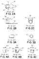
- Fig. 2A is a plan view showing a plug outer contact of the conventional coaxial connector plug;
- Fig. 2B is a front view of the plug outer contact of Fig. 2A;
- Fig. 2C is a right side view of the plug outer contact of Fig. 2A;
- Fig. 3A is a front view showing a clamp ring in the conventional coaxial connector plug;
- Fig. 3B is a right side view of the clamp ring of Fig. 3A;
- Fig. 4A is a left side view showing a plug insulator in a conventional coaxial connector;
- Fig. 4B is a front sectional view of the plug insulator of Fig. 4A;
- Fig. 4C is a right side view of the plug insulator of Fig. 4A;
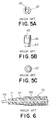
- Fig. 5A is a plan view showing a plug inner contact in the conventional coaxial connector plug;
- Fig. 5B is a front view of the plug inner contact of Fig. 5A;
- Fig. 5C is a bottom view of the plug inner contact of Fig. 5A;
- Fig. 6 is a sectional view showing a structure of one end portion of the conventional coaxial cable;
- Fig. 7A is a sectional view showing a state of the conventional coaxial connector before an inner conductor of the coaxial cable is connected to the inner contact of the coaxial connector plug;
- Fig. 7B is a sectional view showing a state after the inner conductor being fixed to the inner contact by soldering;
- Fig. 7C is a sectional view showing a completed state of the plug after covers are attached to the state of Fig. 7B;
- Fig. 8A is a sectional view of the conventional coaxial connector showing a state before a clamp ring is deformed;
- Fig. 8B is a sectional view showing a state after the clamp ring is deformed;
- Fig. 9A is a front sectional view showing a conventional coaxial connector receptacle;
- Fig. 9B is a plan view of the coaxial connector receptacle of Fig. 9A;
- Fig. 10A is a plan view showing a receptacle outer contact of the conventional coaxial connector receptacle;
- Fig. 10B is a front sectional view of the receptacle outer contact of Fig. 10A;
- Fig. 10C is a plan view showing the receptacle outer contact of Fig. 10A but after a terminal fixing portion is worked;
- Fig. 10D is a front sectional view of the worked receptacle outer contact of Fig. 10C;
- Fig. 11A is a plan view showing a receptacle insulator of the conventional coaxial connector receptacle;
- Fig. 11B is a front sectional view of the receptacle insulator of Fig. 11A;
- Fig. 12A is a plan view showing a central contact of the conventional connector receptacle;
- Fig. 12B is a front view of the central contact of Fig. 12A;
- Fig. 13A is a plan view showing the coaxial connector according to an embodiment of this invention;
- Fig. 13B is a front view of the coaxial connector of Fig. 13A;
- Fig. 13C is a side view of the coaxial connector of Fig. 13A;
- Fig. 14A is a half-sectional plan view of the coaxial connector of Fig. 13A;
- Fig. 14B is a vertical sectional view of the coaxial connector of Fig. 13A;
- Fig. 14C is a half-sectional side view of the coaxial connector of Fig. 13A;
- Fig. 15A is a plan view showing a coaxial connector plug according to the embodiment of this invention;
- Fig. 15B is a side view of the coaxial connector plug of Fig. 15A;
- Fig. 15C is a front view of the coaxial connector plug of Fig. 15A;
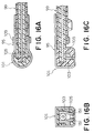
- Fig. 16A is a sectional view of the coaxial connector plug taken along a
line 16A-16A in Fig. 15C; - Fig. 16B is a sectional view taken along a
line 16B-16B in Fig. 15A; - Fig. 16C is a sectional view taken along a
line 16C-16C in Fig. 15A; - Fig. 17A is a plan view showing a plug outer contact of the coaxial connector plug of Fig. 15A;
- Fig. 17B is a front view of the plug outer contact of Fig. 17A;
- Fig. 17C is a side view of the plug outer contact of Fig. 17A;
- Fig. 18A is a plan view showing a plug insulator of the coaxial connector plug of Fig. 15A;
- Fig. 18B is a front sectional view of the plug insulator of Fig. 18A;
- Fig. 18C is a side view of the plug insulator of Fig. 18A;
- Fig. 19A is a plan view showing a plug inner contact of the coaxial connector plug of Fig. 15A;
- Fig. 19B is a front view of the plug inner contact of Fig. 19A;
- Fig. 19C is a side view of the plug inner contact of Fig. 19A;
- Fig. 20 is a vertical sectional view showing a structure of one end portion of the coaxial cable in the embodiment of this invention;
- Fig. 21 is a view showing an open state of the coaxial connector plug of Figs. 15A-15C for connection with the coaxial cable;
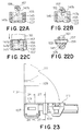
- Figs. 22A-22D are views for illustrating press-contact processes between an inner conductor of the coaxial cable and the inner contact of the coaxial connector plug of Fig. 21, Fig. 22A showing a state before contact, Fig. 22B showing a state of the cable positioned, Fig. 22C showing a state of being press-contacted by a press-contact tool, and Fig. 22D showing a side view of the press-contact process of Fig. 22C;
- Fig. 23 is a view for illustrating a connection process between the plug outer contact of the coaxial connector plug of Figs. 15A-15C and the coaxial cable;
- Fig. 24 is a sectional view taken along a line 24-24 in Fig. 23;
- Figs. 25A-25D are views for illustrating press-bonding processes between a press-bonding portion of an outer contact of the coaxial connector plug and the coaxial cable, Fig. 25A showing a positioning of the cable, Fig. 25B showing a progressed positioning process of the cable, Fig. 25C showing a state in the middle of the press-bonding by a press-bonding tool, and Fig. 25D showing a state after completion of the press-bonding by the press-bonding tool;
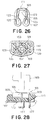
- Fig. 26 is a view showing elasticity of the cable press-bonding portion in a state after the completion of the press-bonding illustrated in Figs 25A to 25D;
- Fig. 27 is a sectional view taken along a line 27-27 in Fig. 23;
- Fig. 28 is a sectional view showing an assembly of a coaxial connector receptacle according to the embodiment of this invention;
- Fig. 29A is a plan view showing a receptacle outer contact of the coaxial connector receptacle of Fig. 28;
- Fig. 29B is a half-sectional front view showing the receptacle outer contact of Fig. 29A;
- Fig. 30A is a plan view showing a receptacle insulator of the coaxial connector receptacle of Fig. 28; and
- Fig. 30B is a front sectional view showing the receptacle insulator of Fig. 30A.
- Before description is made as regards a preferred embodiment, a conventional connector is described with reference to Figs. 1 to 12 to understand the invention more easily.
- As shown in Fig. 1A, the conventional coaxial connector comprises a
coaxial connector plug 31 and a coaxial connector receptacle 33 (see Fig. 9A) which can be mated and electrically connected with each other. - As shown in Figs. 1A and 1B, the
coaxial connector plug 31 comprises a plugouter contact 39 connected to anouter conductor 37 of acoaxial cable 35, aclamp ring 41 for clamping the plugouter contact 39 to thecoaxial cable 35, a pluginner contact 45 electrically connected to aninner conductor 43 of thecoaxial cable 35, and aninsulator 47 for insulating the pluginner contact 45 from the plugouter contact 39. - With reference to Figs. 2A, 2B, and 2C, the plug
outer contact 39 comprises a generally cylindricalouter shell portion 49, an outer contactcable guide portion 51 extending from theouter shell portion 49 in a perpendicular direction, and acover portion 53 extending from a part of theouter shell portion 49 in its axial direction. The outer peripheral surface of theouter shell portion 49 forms afirst contact portion 55 brought into contact with thecoaxial connector receptacle 33, and thecable guide portion 51 forms a second contact portion brought into contact with theouter conductor 37 of thecoaxial cable 35. - The
clamp ring 41 is, as shown in Figs. 3A and 3B, formed in a cylindrical shape so that thecoaxial cable 35 can be inserted thereinto. - As illustrated in Figs. 4A, 4B, and 4C, the
plug insulator 47 has acylindrical body 57 capable of being received within theouter shell portion 49 of the plugouter contact 39. Thebody 57 has an innercontact insertion hole 59 capable of receiving the pluginner contact 45. An insulatorcable guide portion 61 extends from thebody 57 in a perpendicular direction. Thebody 57 is provided with acover 63 for closing an upper opening thereof. - Referring to Figs. 5A, 5B, and 5C, the plug
inner contact 45 has a shape capable of being inserted in the innercontact insertion hole 59. At the upper portion of the pluginner contact 45, an innerconductor contact portion 65 is formed for being brought into contact with the inner conductor 43 (see Figs. 1 and 6) of thecoaxial cable 35. On the other hand, at the lower portion of the pluginner contact 45, an innercontact contact portion 67 having a smaller diameter is formed so as to be brought into contact with the receptacle inner contact of thecoaxial connector receptacle 33. The innerconductor contact portion 65 has a grooved recess formed in a radial direction so as to be able to receive theinner conductor 43 of thecoaxial cable 35. - As shown in Fig. 6, the
coaxial cable 35 comprises asheath 69, theouter conductor 37, aninsulator 71, and theinner conductor 43. An end connecting portion of thecoaxial cable 35 is processed so that those are exposed and arranged in a stepped form. - With reference to Figs. 1A and 1B again, description will now be made as regards assembling processes of the
coaxial connector plug 31. Theplug insulator 47 is received in theouter shell portion 49 of the plugouter contact 39. Then, the pluginner contact 45 is received within theplug insulator 47. Thecoaxial cable 35 is disposed so that theinner conductor 43 is put on the pluginner contact 45, theinsulator 71 is put on thecable guide portion 61 of theplug insulator 47, and theouter conductor 37 is put on thecable guide portion 51 of the plugouter contact 39. Thereafter, theinner conductor 43 is covered with thecover 63 thereupon. Next, acover portion 53 of theouter contact 39 is bent over and located on thecover 63 and theclamp ring 41 is moved in an axial direction and is deformed to clamp thecable 35. - As shown in Figs. 7A, 7B, and 7C, after the
inner conductor 43 of thecoaxial cable 35 is put on the innerconductor contact portion 65 of theinner contact 45, electrical and mechanical connection of them is carried out bysolder 73. Thereafter, electrical insulation from the plugouter contact 39 is done by covering with theinner cover 63. Additionally, theouter cover portion 53 is mounted thereon. - As shown in Fig. 8A, after the
clamp ring 41 is moved in the axial direction and located outside thecable guide portion 51 forming a contact portion, deformation is carried out as shown in Fig. 8B. As a result, thecable guide portion 51 and theouter conductor 37 are electrically connected. - Next, description is made as regards the conventional
coaxial connector receptacle 33 with reference to Figs. 9 to 12. As shown in Fig. 9, thecoaxial connector receptacle 33 comprises a receptacleouter contact 75 fitted and electrically connected to the plugouter contact 39 of thecoaxial connector plug 31, areceptacle insulator 77 being received within the receptacleouter contact 75, and acentral contact 79 penetrating the central part of thereceptacle insulator 77. - As illustrated in Figs. 10A, 10B, 10C, and 10D, the receptacle
outer contact 75 comprises a cylindricalthird contact portion 81 fittable to the plugouter contact 39 of thecoaxial connector plug 31, a cylindricalinsulator holding portion 83 connected to thethird contact portion 81, and leg-liketerminal fixing portions 85 extending downward from theinsulator holding portion 83. At the upper part of thecontact portion 81, anopening 87 is formed which is capable of inserting theouter shell portion 49 of thecoaxial connector plug 31 therein. When theterminal fixing portions 85 are mounted on a printed circuit board which is not shown in figures, it is perpendicularly bent outwardly. - In Figs. 11A and 11B, the
cylindrical receptacle insulator 77 is provided with a centralcontact insertion hole 89 in the central part thereof. - As shown in Figs. 12A and 12B, the
central contact 79 is formed in a stick-shape and comprises aninner contact portion 79a for use as a fourth contact portion electrically brought into contact with the plug inner contact 45 (see Figs. 5A, 5B, and 5C) of thecoaxial connector plug 31, aterminal fixing portion 79b electrically connected to a terminal at a printed circuit board-side, and a fixingtooth 79c for fixing thecentral contact 79 itself to the receptacle insulator 77 (see Fig. 10). - With reference to Fig. 9 again, the
receptacle insulator 77 is received in theinsulator holding portion 83 of the receptacleouter contact 75. In the centralcontact insertion hole 89 of theinsulator 77, thecentral contact 79 is inserted. The fixingtooth 79c of thecentral contact 79 is located within the centralcontact insertion hole 89 so as to prevent thecentral contact 79 from moving in an axial direction. - In the conventional
coaxial connector plug 31, the plugouter contact 39 and theclamp ring 41 for connecting the plugouter contact 39 to thecoaxial cable 35 are prepared as separate parts, respectively. Consequently, the number of parts becomes large and production cost is increased. Additionally, in the conventional coaxial connector plug, soldering is made in an connection between theinner conductor 43 of thecoaxial cable 35 and theinner contact 45. This requires an expert for the soldering and brings a risk that peripheral parts are subjected to a damage due to heat. Furthermore, it is necessary to expose theinner conductor 43 and theouter conductor 37 of thecoaxial cable 35 so as to be connected with the pluginner contact 45 and the plugouter contact 39 of the coaxial connector plug, respectively. This makes a process of the end portion of thecoaxial cable 35 complicated. - Additionally, in the conventional coaxial connector receptacle, the
central contact 79 is press-fitted and fixed to thereceptacle insulator 77. It is therefore necessary to have an equipment and a production-step for the press-fitting operation. This results in a disadvantage that production cost is increased. - Description will now be made as regards a preferred embodiment of this invention with reference to Figs. 13 to 30.
- As shown in Figs. 13A to 13C and 14A to 14C, a
coaxial connector 91 comprises a coaxial connector receptacle (hereinafter called receptacle) 93 and a coaxial connector plug (hereinafter called plug) 95 both of which are fitted and electrically connected each other. Theconnector receptacle 93 is connected to a printed circuit board 97. Acoaxial cable 99 is connected to theplug 95. Theplug 95 is, as shown by an arrow in Fig. 13A, arranged so as to be pivotable over 360 angular degrees on thereceptacle 93. - With reference to Figs. 15A to 15C and 16A to 16C, the
plug 95 comprises a plugouter contact 101, aplug insulator 103 being received within the plugouter contact 101, and a pluginner contact 105 being received within theplug insulator 103.Numerals - With reference to Figs. 17A, 17B, and 17C, the plug
outer contact 101 comprises theouter shell portion 107 capable of being fitted and connected to the receptacle 93 (see Figs. 13 and 14), a press-bonding portion 111 press-bonded and connected to the coaxial cable 99 (see Figs. 13 to 16), and anouter cover portion 113 for closing an opening of theouter shell portion 107. Theouter shell portion 107 is formed in a generally cylindrical shape and forms a first contact portion. At the outer periphery of a fitting portion of theouter shell portion 107 fitted into thereceptacle 93, a plurality of projections, pads, or dowels 115 (for example, three to four points) are formed to ensure an electrical contact with thereceptacle 93. Theouter shell portion 107 has an outer peripheral wall having anopening 117 for operating an extracting-tool therethrough. In addition, from one end of the outer peripheral wall of theouter shell portion 107, acable guide portion 119 for guiding thecoaxial cable 99 extends perpendicularly in a direction along the central axis of theouter shell portion 107. Theouter cover portion 113 serves also as a coupling portion for coupling theouter shell portion 107 with the press-bonding portion 111. Theouter cover portion 113 is formed integral with theouter shell portion 107 and the press-bonding portion 111. Between thecover portion 113 and the press-bonding portion 111, a pair ofband portions 109 is formed to hold thecoaxial cable 99. The press-bonding portion 111 acts as a second contact brought into contact with the outer conductor of the coaxial cable. As understood from Fig. 17C, the press-bonding portion 111 comprises a pair of first press-bondingpieces 123 projecting in a U-shape or a V-shape from abase 121 and a pair of second press-bondingpieces 125 projecting longer than the first press-bondingpieces 123. A projecting end or tip of each of the press-bondingpieces coaxial cable 99. The second press-bondingpieces 125 haveguide portions 127 for guiding and centering thecoaxial cable 99. - Referring to Figs. 18A, 18B, and 18C, the
insulator 103 comprises a substantiallycylindrical body 129 capable of being received in theouter shell portion 107 of the plugouter contact 101 and an insulatingcover 133 connected to thebody 129 through ahinge 131. Thebody 129 comprises an innercontact receiving portion 135 for receiving the plug inner contact 105 (see Figs. 15and 16), aguide hole 137 for guiding the contact portion of theinner contact 105, aguide groove 139 for guiding the coaxial cable 99 (see Figs. 13 to 16), and an innercable guide portion 141. The innercable guide portion 141 projects outwardly in a perpendicular direction to the central axis of thebody 129. One end of thebody 129 has an opening portion 143 which is closed by the insulatingcover 133. - In Figs. 19A, 19B, and 19C, the plug
inner contact 105 is formed in a link shape and has a press-contact portion 145. In the central part of the press-contact portion 145, aU-shaped groove 147a is formed to be brought into contact with the inner conductor of the coaxial cable 99 (see Figs. 13 to 16). At the both sides of theU-shaped groove 147a, a pair of press-contact blades 147b is formed to divergently expand upwardly. The press-contact blades 147b penetrate the inner insulator of thecoaxial cable 99 so that the press-contact portion 145 is electrically connected to the inner conductor of thecoaxial cable 99. The pluginner contact 105 has a pair ofspring portions 149 extending downward. The lower end of each ofspring portions 149 has aninner contact portion 151 brought into contact with the inner contact of thereceptacle 93. - As illustrated in Fig. 20, the
coaxial cable 99 comprises asheath 153, anouter conductor 155, aninner insulator 157, and aninner conductor 159. The end portion of thecoaxial cable 99 is processed different from that of the conventional coaxial cable in that thesheath 153 and theouter conductor 155 are partly removed at one end portion of thecoaxial cable 99 so that theinner insulator 157 and theinner conductor 159 are projected with both substantially equal length from the common end of thesheath 153 and theouter conductor 155. - With reference to Figs. 21 to 28, description will be made as regards an operation of connecting the
coaxial cable 99 to thecoaxial connector plug 95. - As shown in Fig. 21, the
insulator 103 is received within theouter shell portion 107 of theouter contact 101. Theinsulator 103 has the inner contact receiving portion 135 (see Fig. 18) in which theinner contact 105 is received. Thereafter, thecoaxial cable 99 with one end thereof processed is disposed on theplug 95. Thecoaxial cable 99 is positioned so that theinner insulator 157 and theinner conductor 159 are inserted in theguide groove 139 of theinsulator 103. Then, as illustrated in Figs. 22A, 22B, 22C, and 22D, theinner insulator 157 and theinner conductor 159 of the coaxial cable 99 (see Fig. 20) are disposed on the press-contact blades 147b of theinner contact 105 of theplug 95. With this condition, a press-contact tool 161 is operated. By this operation, theinner insulator 157 of thecoaxial cable 99 is cut by the press-contact blades 147b of theinner contact 105. At the same time, theinner conductor 159 of thecoaxial cable 99 is forced into theU-shaped groove 147a of theinner contact 105 to be electrically connected. Thereafter, the insulating cover 133 (see Fig. 21) of theinsulator 103 is bent at thehinge 131 so that the opening portion 143 (see Fig. 18) is closed. Simultaneously, theinner contact 105 is insulated from the outer contact 101 (see Figs. 15 and 16). As illustrated in Figs. 23 and 24, thecover portion 113 of the outer contact 101 (see Figs. 15 and 16) is bent perpendicularly at the connecting portion with theouter shell portion 107. Then, the press-bonding portion 111 is press-bonded to thecoaxial cable 99. Additionally, theband portion 109 is wound around the outer periphery of the coaxial cable 99 (see Fig. 15C). - With reference to Figs. 25A, 25B, 25C, and 25D, the
coaxial cable 99 is guided by theguide portion 127 to be centered in the press-bonding portion 111. Thereafter, press-bonding is carried out by the press-bonding tool 163. The pair of first press-bondingpieces 123 penetrate thesheath 153 and proceed further so as to bite into a boundary between theouter conductor 155 and theinner insulator 157. On the other hand, the tip portion of each of the second press-bondingpieces 125 is crimped by the press-bonding tool 163. Accordingly, the tip portion penetrates thesheath 153 and proceeds so as to bite into between thesheath 153 and theouter conductor 155. - Referring to Fig. 26, the first and the second press-bonding
pieces arrows outer conductor 155 of thecoaxial cable 99 is put between the press-bonding pieces to ensure reliable electrical contact. - As shown in Fig. 27, the
band portion 109 is wound around the periphery of thecoaxial cable 99 and thecable guide portions coaxial cable 99. - With reference to Figs. 28, 29A, 29B, 30A, and 30B, description is made as regards the
receptacle 93. As shown in Fig. 28, thereceptacle 93 comprises a receptacleouter contact 169, areceptacle insulator 171, and a receptacleinner contact 173. As illustrated in Figs. 29A and 29B, the receptacleouter contact 169 has a cylindricalthird contact portion 175 to which the plugouter contact 101 of the plug 95 (see Fig. 21) is fitted and electrically connected. A plurality of (for example, three) leg-liketerminal portions 177 extend downward from thethird contact portion 175. Thecontact portion 175 has anopening 179 in which the plugouter contact 101 of theplug 95 is inserted. - As shown in Figs. 30A and 30B, the
receptacle insulator 171 of thereceptacle 93 has a plurality ofinsertion holes 181 being used as a receiving portion in which the terminal portions 177 (see Fig. 29B) of the receptacleouter contact 169 are inserted and received. Thereceptacle insulator 171 has also adepressed guide portion 183 for receiving thethird contact portion 175 of the receptacleouter contact 169. In the central part of thereceptacle insulator 171, the receptacleinner contact 173 press-formed is molded. The receptacleinner contact 173 comprises afourth contact portion 185 electrically brought into contact with thecontact portion 151 of the pluginner contact 105 of the plug 95 (see Fig. 21) and aterminal portion 187 electrically connected to the printed circuit board 97 illustrated in Fig. 13. - Returning to Fig. 28, the receptacle
outer contact 169 is perpendicularly bent after theterminal portions 177 are inserted in the insertion holes 181 of thereceptacle insulator 171. The bentterminal portions 177 are electrically connected to the printed circuit board 97 illustrated in Fig. 13. - According to the above-mentioned preferred embodiment, the
outer shell portion 107 of the plugouter contact 101 as the first contact portion which is brought into contact with the outer conductor of the coaxial cable of theplug 95, the press-bonding portion 111 as the second contact portion having the press-bonding pieces arranged to surround thecoaxial cable 99, and theband portion 109 are integrally coupled through thecover portion 113 as the coupling portion. Thus, it is not necessary to use the conventional clamp ring as a separate part. This results in a reduction of the number of parts and of cost of parts. This also makes it possible to reduce production cost. In addition, it is possible to lower a height of the coaxial connector after thecoaxial cable 99 is connected thereto since the clamp ring becomes unnecessary. - Therefore, miniaturization of the coaxial connector can be achieved.
- Additionally, according to this invention, the
inner conductor 159 of thecoaxial cable 99 is press-contacted with the pluginner contact 163 of theplug 95 and the plugouter contact 101 of theplug 95 is press-bonded to theouter conductor 155 of thecoaxial cable 99 by the press-bonding portion 111 having the first and the second press-bonding pieces (123, 125). Accordingly, electrical connection between theplug 95 and thecoaxial cable 99 can be carried out extremely easily by the use of the press-bonding tool and the press-contact tool. As a result, connection operation with thecoaxial cable 99 becomes remarkably simple and production step of assembling can be reduced. Moreover, it is possible to further reduce production step of processing and to simplify processing treatment of the end portion of thecoaxial cable 99 because press-bonding process of the press-bonding portion 111 is carried out when closing thecover portion 113. Additionally, in the receptacle, theinner contact 173 is molded in theinsulator 171, so that press-fitting of the inner contact is not necessary. It is therefore possible to reduce the receptacle assembling time and to miniaturize the receptacle. - Furthermore, the plug
inner contact 163 of thecoaxial connector plug 95 has the press-contact piece press-contacted with theinner conductor 159 of thecoaxial cable 99. In this case, conventional soldering operation is no longer needed. It is possible to prevent the peripheral parts from such as damages due to heat and to carry out connection operation extremely easily without requiring skill.
Claims (16)
- A coaxial connector plug (95) comprising a plug outer contact (101) having a first contact portion (107) to be brought into contact with a receptacle outer contact (169) of a coaxial connector receptacle (93) and a second contact portion (111) to be brought into contact with an outer conductor (155) of a coaxial cable (99),
wherein said first contact portion and said second contact portion are integrally coupled by way of a coupling portion (113), said second contact portion having a plurality of press-bonding pieces (123, 125) for penetrating a sheath (153) of said coaxial cable to come into contact with said outer conductor of said coaxial cable, said press-bonding pieces being arranged so as to surround said coaxial cable. - A coaxial connector plug as claimed in Claim 1, further comprising a plug inner contact (105) having a press-contact portion (147) to be press-contacted with an inner conductor of said coaxial cable.
- A coaxial connector plug as claimed in Claim 1 or 2, wherein said coupling portion and said press-bonding pieces are separated by a predetermined distance.
- A coaxial connector plug as claimed in one of Claims 1 to 3, wherein said plug outer contact comprises a plug insulator (103) for receiving one end portion of said coaxial cable and an insulator receiving portion (107) located at said first contact portion to hold said plug insulator.
- A coaxial connector plug as claimed in one of Claims 2 to 4, wherein said press-contact portion comprises a slitted groove (147a) and a press-contact blade (147b) formed at both sides of an opening of said slitted groove so as to penetrate an insulator (157) formed at the periphery of said inner conductor of said coaxial cable to be brought into contact with said inner conductor, said plug inner contact (105) preferably being received within said insulator.
- A coaxial connector plug as claimed in one of Claims 1 to 5, said plurality of press-bonding pieces comprise a first press-bonding piece (123) for penetrating said coaxial cable inside said outer conductor and a second press-bonding piece (125) for penetrating said coaxial cable outside said outer conductor, whereby said outer conductor is partially held between said first press-bonding piece and said second press-bonding piece.
- A coaxial connector plug as claimed in Claim 5 or 6, wherein said coaxial cable has a connection end portion having a shape that said outer conductor is covered with said sheath and said inner conductor covered with said insulator projects from said outer conductor in an axial direction.
- A coaxial connector receptacle (93) which is mounted on a printed circuit board (91) and which comprises a receptacle outer contact (169), a receptacle inner contact (173), and a receptacle insulator (171) holding said receptacle outer and inner contacts, wherein said receptacle outer contact has a first conductor portion (177) at one end, said receptacle inner contact having a second conductor portion (187) which is surrounded by said receptacle outer contact of said receptacle insulator and which is exposed at one surface of said receptacle insulator, said receptacle insulator having a receiving portion (181) for receiving said first conductor portion.
- A coaxial connector receptacle as claimed in Claim 8, wherein said receptacle insulator has a surface which is fixed to a surface of said printed circuit board (91).
- A coaxial connector comprising a coaxial connector receptacle (93) having a receptacle outer contact (169), and a coaxial connector plug (95) having a plug outer contact (101) with a first contact portion (107) to be brought into contact with said receptacle outer contact and a second contact portion (111) to be brought into contact with an outer conductor (155) of a coaxial cable (99), wherein said first contact portion and said second contact portion of said coaxial connector plug are integrally coupled by way of a coupling portion (113), said second contact portion having a plurality of press-bonding pieces (123, 127) for penetrating a sheath (153) of said coaxial cable to come into contact with said outer conductor of said coaxial cable, said press-bonding pieces being arranged so as to surround said coaxial cable.
- A coaxial connector as claimed in Claim 10, wherein said coaxial connector plug comprises a plug inner contact (105) having a press-contact portion (145) to be press-contacted with an inner conductor (159) of said coaxial cable.
- A coaxial connector as claimed in Claim 11, wherein said coupling portion and said press-bonding portion are positioned so as to separate each other by a predetermined distance.
- A coaxial connector as claimed in one of Claims 10 to 12, wherein said plug outer contact comprises a plug insulator (103) for receiving one end portion of said coaxial cable and an insulator receiving portion (107) which is located at said first contact portion so as to hold said plug insulator.
- A coaxial connector as claimed in one of Claims 11 to 13, wherein said press-contact portion (145) comprises a slitted groove (147a) and a press-contact blade (147b) formed at both sides of an opening of said slitted groove so that said press-contact portion penetrates an insulator (157) formed at the periphery of said inner conductor of said coaxial cable to be brought into contact with said inner conductor, said plug inner contact preferably being received in said plug insulator.
- A coaxial connector as claimed in one of Claims 10 to 14, wherein said coaxial connector plug is rotatable with respect to said coaxial connector receptacle, said coaxial cable extending in a direction intersecting a central axis of said coaxial connector plug.
- A coaxial connector as claimed in one of Claims 10 to 15, wherein said press-bonding pieces comprise a first press-bonding piece (123) for penetrating said coaxial cable inside said outer conductor (153) and a second press-bonding piece (125) for penetrating said coaxial cable outside said outer conductor (155), whereby said outer conductor is partially held between said first press-bonding piece and said second press-bonding piece.
Applications Claiming Priority (3)
| Application Number | Priority Date | Filing Date | Title |
|---|---|---|---|
| JP25057293 | 1993-10-06 | ||
| JP250572/93 | 1993-10-06 | ||
| JP5250572A JP2665717B2 (en) | 1993-10-06 | 1993-10-06 | Coaxial connector plug |
Publications (3)
| Publication Number | Publication Date |
|---|---|
| EP0647985A2 true EP0647985A2 (en) | 1995-04-12 |
| EP0647985A3 EP0647985A3 (en) | 1996-08-07 |
| EP0647985B1 EP0647985B1 (en) | 2001-08-08 |
Family
ID=17209888
Family Applications (1)
| Application Number | Title | Priority Date | Filing Date |
|---|---|---|---|
| EP94115752A Expired - Lifetime EP0647985B1 (en) | 1993-10-06 | 1994-10-06 | Coaxial connector plug and coaxial connector comprising the same |
Country Status (8)
| Country | Link |
|---|---|
| US (1) | US5569049A (en) |
| EP (1) | EP0647985B1 (en) |
| JP (1) | JP2665717B2 (en) |
| KR (1) | KR100359524B1 (en) |
| CA (1) | CA2133774C (en) |
| DE (1) | DE69427891T2 (en) |
| SG (1) | SG45190A1 (en) |
| TW (1) | TW247973B (en) |
Cited By (5)
| Publication number | Priority date | Publication date | Assignee | Title |
|---|---|---|---|---|
| WO1998043323A1 (en) * | 1997-03-25 | 1998-10-01 | The Whitaker Corporation | Coaxial connector for circuit board |
| EP0945931A2 (en) * | 1998-03-27 | 1999-09-29 | Luigi Ramari | Multi-component electrical connector and manufacturing process |
| US6142803A (en) * | 1997-12-22 | 2000-11-07 | The Whitaker Corporation | Coaxial antenna connector for mobile phone |
| US6547593B1 (en) | 2000-08-07 | 2003-04-15 | Gore Enterprise Holdings, Inc. | Sub-miniature, high speed coaxial pin interconnection system |
| EP1533870A1 (en) * | 2003-11-21 | 2005-05-25 | J.S.T. Mfg. Co., Ltd. | Piercing terminal for coaxial cable |
Families Citing this family (31)
| Publication number | Priority date | Publication date | Assignee | Title |
|---|---|---|---|---|
| JPH0822851A (en) * | 1994-07-07 | 1996-01-23 | Japan Aviation Electron Ind Ltd | Coaxial plug connector |
| JP3120692B2 (en) * | 1995-04-18 | 2000-12-25 | 株式会社村田製作所 | Coaxial connector |
| US6123567A (en) * | 1996-05-15 | 2000-09-26 | Centerpin Technology, Inc. | Coaxial cable connector |
| US5775934A (en) * | 1996-05-15 | 1998-07-07 | Centerpin Technology, Inc. | Coaxial cable connector |
| US5772470A (en) * | 1996-06-03 | 1998-06-30 | Smk Corporation | Coaxial connector |
| JP3421555B2 (en) * | 1997-11-07 | 2003-06-30 | 矢崎総業株式会社 | Connection structure of coaxial cable connector and connection method thereof |
| US6149460A (en) * | 1998-09-25 | 2000-11-21 | Tyco Electronics Logistics Ag | RF plug connection system and method for assembling the RF plug connection system |
| DE29822588U1 (en) * | 1998-12-18 | 2000-04-27 | Bosch Gmbh Robert | Contact element for axial contacting |
| US6305980B2 (en) * | 1999-03-18 | 2001-10-23 | Hon Hai Precision Ind. Co., Ltd. | Cable end connector having accurately positioned connection terminal therein |
| US6705884B1 (en) | 1999-08-16 | 2004-03-16 | Centerpin Technology, Inc. | Electrical connector apparatus and method |
| US6371806B1 (en) * | 2000-11-08 | 2002-04-16 | Hon Hai Precision Ind. Co., Ltd. | Cable end connector having accurately positioned connection terminal therein |
| US6416357B1 (en) * | 2001-03-12 | 2002-07-09 | Hon Hai Precision Ind. Co., Ltd. | Cable end connector with low profile after assembly |
| US6447335B1 (en) * | 2001-07-16 | 2002-09-10 | Hon Hai Precision Ind. Co., Ltd. | Cable end connector |
| US6837743B2 (en) * | 2002-04-05 | 2005-01-04 | Hon Hai Precision Ind. Co., Ltd. | Cable end connector having good insulation function |
| US20030216500A1 (en) * | 2002-04-29 | 2003-11-20 | Mckenna James Michael | Hydrolysis resistant polyester elastomer compositions and related articles and methods |
| DE10346367B4 (en) * | 2002-10-07 | 2016-02-18 | Volkswagen Ag | Freely rotatable HF-angle connector |
| JP3808850B2 (en) * | 2003-07-22 | 2006-08-16 | 日本圧着端子製造株式会社 | Connector for coaxial cable connector |
| JP4083103B2 (en) * | 2003-10-06 | 2008-04-30 | ホシデン株式会社 | Connector for coaxial cable |
| US6916201B1 (en) * | 2004-03-03 | 2005-07-12 | Speed Tech Corp. | Micro coaxial cable connecting device |
| TWM307242U (en) * | 2006-07-14 | 2007-03-01 | Insert Entpr Co Ltd | Improved structure of microwave connector for RF communication |
| US7351067B2 (en) * | 2006-08-09 | 2008-04-01 | Speed Tech Corp. | Coaxial cable connecting apparatus |
| JP2008098125A (en) * | 2006-10-12 | 2008-04-24 | Shintake Sangyo Kk | L-shaped plug and its manufacturing method |
| JP4097681B1 (en) | 2007-02-01 | 2008-06-11 | 日本航空電子工業株式会社 | connector |
| JP4901632B2 (en) * | 2007-07-30 | 2012-03-21 | 矢崎総業株式会社 | Coaxial line connector and coaxial line connection unit |
| TWI401851B (en) * | 2008-01-30 | 2013-07-11 | Harumoto Prec Co Ltd | Cable connector assembly method |
| DE202008014409U1 (en) * | 2008-10-29 | 2009-01-22 | Rosenberger Hochfrequenztechnik Gmbh & Co. Kg | HF right-angle connector |
| JP5523154B2 (en) * | 2010-03-18 | 2014-06-18 | 日本圧着端子製造株式会社 | Coaxial connector and board connector |
| JP5763007B2 (en) * | 2012-04-19 | 2015-08-12 | ヒロセ電機株式会社 | Electrical connector |
| JP5949838B2 (en) * | 2014-06-16 | 2016-07-13 | 第一精工株式会社 | Coaxial electrical connector |
| TWI608678B (en) * | 2016-07-01 | 2017-12-11 | 春源科技(深圳)有限公司 | Method of connecting rf cable end connector and coaxial cable and used internal terminal thereof |
| US11489288B2 (en) * | 2020-08-28 | 2022-11-01 | Raytheon Company | Connector retention clip |
Citations (3)
| Publication number | Priority date | Publication date | Assignee | Title |
|---|---|---|---|---|
| EP0412412A1 (en) * | 1989-08-11 | 1991-02-13 | Murata Manufacturing Co., Ltd. | Connector |
| EP0428162A1 (en) * | 1989-11-15 | 1991-05-22 | Hirose Electric Co., Ltd. | Electrical connector and method of loading same |
| EP0519812A1 (en) * | 1991-06-17 | 1992-12-23 | RADIALL Société anonyme dite: | Coaxial connector for connecting a coaxial cable to an electronic printed circuit |
Family Cites Families (13)
| Publication number | Priority date | Publication date | Assignee | Title |
|---|---|---|---|---|
| US3510827A (en) * | 1967-11-14 | 1970-05-05 | Etc Inc | T-tap connectors |
| US4326769A (en) * | 1980-04-21 | 1982-04-27 | Litton Systems, Inc. | Rotary coaxial assembly |
| US4701137A (en) * | 1983-04-04 | 1987-10-20 | Molex Incorporated | Electrical connector for coaxial cables |
| JP2584265Y2 (en) * | 1985-10-30 | 1998-10-30 | 日本電気株式会社 | Connection structure of electrical connector for coaxial cable |
| US4708414A (en) * | 1987-01-30 | 1987-11-24 | Albert Lam | Electric wire connector for coaxial cable |
| JPH02291679A (en) * | 1989-02-10 | 1990-12-03 | C R T:Kk | Plug for coaxial cable |
| JP2504704B2 (en) * | 1991-03-12 | 1996-06-05 | ヒロセ電機株式会社 | Coaxial cable connector and connection method |
| JP2540805Y2 (en) * | 1991-06-27 | 1997-07-09 | ヒロセ電機株式会社 | Surface mount type high frequency coaxial connector structure |
| JPH05152037A (en) * | 1991-11-30 | 1993-06-18 | Murata Mfg Co Ltd | L-type coaxial connector |
| JPH05234628A (en) * | 1992-02-19 | 1993-09-10 | Murata Mfg Co Ltd | Cable connection structure for coaxial connector |
| JPH05242931A (en) * | 1992-02-26 | 1993-09-21 | Murata Mfg Co Ltd | Coaxial connector |
| US5322453A (en) * | 1992-11-25 | 1994-06-21 | M/A-Com Omni Spectra, Inc. | RF connector jack and plug assembly |
| JP3116678U (en) * | 2005-09-12 | 2005-12-15 | 輝家 小泉 | Beer server |
-
1993
- 1993-10-06 JP JP5250572A patent/JP2665717B2/en not_active Expired - Fee Related
-
1994
- 1994-10-05 US US08/330,721 patent/US5569049A/en not_active Expired - Lifetime
- 1994-10-06 SG SG1996001106A patent/SG45190A1/en unknown
- 1994-10-06 KR KR1019940025530A patent/KR100359524B1/en not_active IP Right Cessation
- 1994-10-06 DE DE69427891T patent/DE69427891T2/en not_active Expired - Fee Related
- 1994-10-06 TW TW083109363A patent/TW247973B/zh not_active IP Right Cessation
- 1994-10-06 EP EP94115752A patent/EP0647985B1/en not_active Expired - Lifetime
- 1994-10-06 CA CA002133774A patent/CA2133774C/en not_active Expired - Fee Related
Patent Citations (3)
| Publication number | Priority date | Publication date | Assignee | Title |
|---|---|---|---|---|
| EP0412412A1 (en) * | 1989-08-11 | 1991-02-13 | Murata Manufacturing Co., Ltd. | Connector |
| EP0428162A1 (en) * | 1989-11-15 | 1991-05-22 | Hirose Electric Co., Ltd. | Electrical connector and method of loading same |
| EP0519812A1 (en) * | 1991-06-17 | 1992-12-23 | RADIALL Société anonyme dite: | Coaxial connector for connecting a coaxial cable to an electronic printed circuit |
Non-Patent Citations (1)
| Title |
|---|
| JEE JOURNAL OF ELECTRONIC ENGINEERING, vol. 29, no. 303, 1 March 1992 pages 81-84, XP 000298154 KENSHI MICHISHITA 'COAXIAL CONNECTOR TECHNIQUES ACCOMMODATE HIGH FREQUENCY, SMT' * |
Cited By (7)
| Publication number | Priority date | Publication date | Assignee | Title |
|---|---|---|---|---|
| WO1998043323A1 (en) * | 1997-03-25 | 1998-10-01 | The Whitaker Corporation | Coaxial connector for circuit board |
| US6142803A (en) * | 1997-12-22 | 2000-11-07 | The Whitaker Corporation | Coaxial antenna connector for mobile phone |
| EP0945931A2 (en) * | 1998-03-27 | 1999-09-29 | Luigi Ramari | Multi-component electrical connector and manufacturing process |
| EP0945931A3 (en) * | 1998-03-27 | 2002-04-03 | Luigi Ramari | Multi-component electrical connector and manufacturing process |
| US6547593B1 (en) | 2000-08-07 | 2003-04-15 | Gore Enterprise Holdings, Inc. | Sub-miniature, high speed coaxial pin interconnection system |
| EP1533870A1 (en) * | 2003-11-21 | 2005-05-25 | J.S.T. Mfg. Co., Ltd. | Piercing terminal for coaxial cable |
| US7001203B2 (en) | 2003-11-21 | 2006-02-21 | J.S.T. Mfg. Co., Ltd. | Piercing terminal for coaxial cable |
Also Published As
| Publication number | Publication date |
|---|---|
| CA2133774A1 (en) | 1995-04-07 |
| CA2133774C (en) | 1999-08-24 |
| DE69427891D1 (en) | 2001-09-13 |
| SG45190A1 (en) | 1998-01-16 |
| KR100359524B1 (en) | 2003-01-24 |
| DE69427891T2 (en) | 2002-04-11 |
| US5569049A (en) | 1996-10-29 |
| EP0647985A3 (en) | 1996-08-07 |
| JP2665717B2 (en) | 1997-10-22 |
| JPH07106002A (en) | 1995-04-21 |
| EP0647985B1 (en) | 2001-08-08 |
| TW247973B (en) | 1995-05-21 |
Similar Documents
| Publication | Publication Date | Title |
|---|---|---|
| US5569049A (en) | Coaxial connector plug having sheath penetrating contacts and receptacle for receiving the same | |
| EP0327308B1 (en) | Microcoaxial connector family | |
| EP0001701B1 (en) | Electrical connector for terminating coaxial cable | |
| US7819694B2 (en) | Electrical connector | |
| EP0276549B1 (en) | Electrical connector and method of assembly | |
| US8894444B2 (en) | Coaxial electrical connector and coaxial electrical connector assembly including a tubular contact for reducing the height and improving the retention strength against mating or removal | |
| EP3159970A1 (en) | Cable assembly, connector, and method for manufacturing cable assembly | |
| US20060246776A1 (en) | Connector suitable for connection of a coaxial cable | |
| JPH0526706Y2 (en) | ||
| US6254430B1 (en) | Coaxial connector | |
| JPH0379834B2 (en) | ||
| US20030224658A1 (en) | Electrical connector | |
| EP0525249B1 (en) | Electrical connector and method of connecting shielded cable to same | |
| US5885104A (en) | Electrical plug connector | |
| EP0090538A2 (en) | Right angle coaxial connector | |
| US4927378A (en) | Lead wire connecting device for coaxial cable connector | |
| JP6792286B2 (en) | Coaxial connector | |
| JP2003178845A (en) | Connector | |
| JPH08153557A (en) | Female terminal and coaxial connector using it | |
| US11509104B2 (en) | Short-circuit probe, plug-in connection with such a short-circuit probe and a method for producing such a short-circuit probe | |
| JP2001307841A (en) | Coaxial connector | |
| JPH0625903Y2 (en) | Coaxial connector | |
| JPH0822851A (en) | Coaxial plug connector | |
| CA1280185C (en) | Electrical connector and method of assembly | |
| WO1995016291A1 (en) | Connector |
Legal Events
| Date | Code | Title | Description |
|---|---|---|---|
| PUAI | Public reference made under article 153(3) epc to a published international application that has entered the european phase |
Free format text: ORIGINAL CODE: 0009012 |
|
| AK | Designated contracting states |
Kind code of ref document: A2 Designated state(s): DE FR GB IT NL SE |
|
| PUAL | Search report despatched |
Free format text: ORIGINAL CODE: 0009013 |
|
| AK | Designated contracting states |
Kind code of ref document: A3 Designated state(s): DE FR GB IT NL SE |
|
| 17P | Request for examination filed |
Effective date: 19961223 |
|
| 17Q | First examination report despatched |
Effective date: 19990215 |
|
| RTI1 | Title (correction) |
Free format text: COAXIAL CONNECTOR PLUG AND COAXIAL CONNECTOR COMPRISING THE SAME |
|
| GRAG | Despatch of communication of intention to grant |
Free format text: ORIGINAL CODE: EPIDOS AGRA |
|
| GRAG | Despatch of communication of intention to grant |
Free format text: ORIGINAL CODE: EPIDOS AGRA |
|
| GRAH | Despatch of communication of intention to grant a patent |
Free format text: ORIGINAL CODE: EPIDOS IGRA |
|
| GRAH | Despatch of communication of intention to grant a patent |
Free format text: ORIGINAL CODE: EPIDOS IGRA |
|
| GRAA | (expected) grant |
Free format text: ORIGINAL CODE: 0009210 |
|
| ITF | It: translation for a ep patent filed |
Owner name: BARZANO' E ZANARDO MILANO S.P.A. |
|
| RIC1 | Information provided on ipc code assigned before grant |
Free format text: 7H 01R 9/05 A, 7H 01R 13/646 B |
|
| AK | Designated contracting states |
Kind code of ref document: B1 Designated state(s): DE FR GB IT NL SE |
|
| REF | Corresponds to: |
Ref document number: 69427891 Country of ref document: DE Date of ref document: 20010913 |
|
| ET | Fr: translation filed | ||
| REG | Reference to a national code |
Ref country code: GB Ref legal event code: IF02 |
|
| PLBE | No opposition filed within time limit |
Free format text: ORIGINAL CODE: 0009261 |
|
| STAA | Information on the status of an ep patent application or granted ep patent |
Free format text: STATUS: NO OPPOSITION FILED WITHIN TIME LIMIT |
|
| 26N | No opposition filed | ||
| PGFP | Annual fee paid to national office [announced via postgrant information from national office to epo] |
Ref country code: NL Payment date: 20071030 Year of fee payment: 14 Ref country code: DE Payment date: 20071031 Year of fee payment: 14 |
|
| PGFP | Annual fee paid to national office [announced via postgrant information from national office to epo] |
Ref country code: IT Payment date: 20071004 Year of fee payment: 14 |
|
| PGFP | Annual fee paid to national office [announced via postgrant information from national office to epo] |
Ref country code: SE Payment date: 20071008 Year of fee payment: 14 |
|
| PGFP | Annual fee paid to national office [announced via postgrant information from national office to epo] |
Ref country code: GB Payment date: 20071001 Year of fee payment: 14 Ref country code: FR Payment date: 20071029 Year of fee payment: 14 |
|
| EUG | Se: european patent has lapsed | ||
| GBPC | Gb: european patent ceased through non-payment of renewal fee |
Effective date: 20081006 |
|
| NLV4 | Nl: lapsed or anulled due to non-payment of the annual fee |
Effective date: 20090501 |
|
| REG | Reference to a national code |
Ref country code: FR Ref legal event code: ST Effective date: 20090630 |
|
| PG25 | Lapsed in a contracting state [announced via postgrant information from national office to epo] |
Ref country code: NL Free format text: LAPSE BECAUSE OF NON-PAYMENT OF DUE FEES Effective date: 20090501 |
|
| PG25 | Lapsed in a contracting state [announced via postgrant information from national office to epo] |
Ref country code: IT Free format text: LAPSE BECAUSE OF NON-PAYMENT OF DUE FEES Effective date: 20081006 Ref country code: DE Free format text: LAPSE BECAUSE OF NON-PAYMENT OF DUE FEES Effective date: 20090501 |
|
| PG25 | Lapsed in a contracting state [announced via postgrant information from national office to epo] |
Ref country code: FR Free format text: LAPSE BECAUSE OF NON-PAYMENT OF DUE FEES Effective date: 20081031 |
|
| PG25 | Lapsed in a contracting state [announced via postgrant information from national office to epo] |
Ref country code: GB Free format text: LAPSE BECAUSE OF NON-PAYMENT OF DUE FEES Effective date: 20081006 |
|
| PG25 | Lapsed in a contracting state [announced via postgrant information from national office to epo] |
Ref country code: SE Free format text: LAPSE BECAUSE OF NON-PAYMENT OF DUE FEES Effective date: 20081007 |