EP0653191A2 - Safety penetrating instrument - Google Patents
Safety penetrating instrument Download PDFInfo
- Publication number
- EP0653191A2 EP0653191A2 EP95101028A EP95101028A EP0653191A2 EP 0653191 A2 EP0653191 A2 EP 0653191A2 EP 95101028 A EP95101028 A EP 95101028A EP 95101028 A EP95101028 A EP 95101028A EP 0653191 A2 EP0653191 A2 EP 0653191A2
- Authority
- EP
- European Patent Office
- Prior art keywords
- needle
- distal end
- safety
- safety probe
- probe
- Prior art date
- Legal status (The legal status is an assumption and is not a legal conclusion. Google has not performed a legal analysis and makes no representation as to the accuracy of the status listed.)
- Withdrawn
Links
- 230000000149 penetrating effect Effects 0.000 title claims abstract description 92
- 239000000523 sample Substances 0.000 claims abstract description 138
- 230000002093 peripheral effect Effects 0.000 claims abstract description 18
- 230000001154 acute effect Effects 0.000 claims abstract description 7
- 210000001519 tissue Anatomy 0.000 description 45
- 230000035515 penetration Effects 0.000 description 32
- 230000004048 modification Effects 0.000 description 12
- 238000012986 modification Methods 0.000 description 12
- 238000000034 method Methods 0.000 description 11
- 230000001419 dependent effect Effects 0.000 description 9
- 239000004033 plastic Substances 0.000 description 8
- 229920003023 plastic Polymers 0.000 description 8
- 239000012530 fluid Substances 0.000 description 7
- 238000001574 biopsy Methods 0.000 description 6
- 238000004891 communication Methods 0.000 description 6
- 230000001681 protective effect Effects 0.000 description 6
- 239000000463 material Substances 0.000 description 5
- 239000010935 stainless steel Substances 0.000 description 5
- 229910001220 stainless steel Inorganic materials 0.000 description 5
- 210000001367 artery Anatomy 0.000 description 4
- 210000003462 vein Anatomy 0.000 description 4
- 210000002445 nipple Anatomy 0.000 description 3
- 206010018852 Haematoma Diseases 0.000 description 2
- 208000005646 Pneumoperitoneum Diseases 0.000 description 2
- 239000004809 Teflon Substances 0.000 description 2
- 229920006362 Teflon® Polymers 0.000 description 2
- 208000027418 Wounds and injury Diseases 0.000 description 2
- 230000006835 compression Effects 0.000 description 2
- 238000007906 compression Methods 0.000 description 2
- 238000002347 injection Methods 0.000 description 2
- 239000007924 injection Substances 0.000 description 2
- 208000014674 injury Diseases 0.000 description 2
- 210000003281 pleural cavity Anatomy 0.000 description 2
- 238000001356 surgical procedure Methods 0.000 description 2
- 230000008733 trauma Effects 0.000 description 2
- 239000004677 Nylon Substances 0.000 description 1
- 241001639412 Verres Species 0.000 description 1
- 210000001015 abdomen Anatomy 0.000 description 1
- 238000005452 bending Methods 0.000 description 1
- 210000004204 blood vessel Anatomy 0.000 description 1
- 239000004568 cement Substances 0.000 description 1
- 238000010276 construction Methods 0.000 description 1
- 229920001971 elastomer Polymers 0.000 description 1
- 210000001308 heart ventricle Anatomy 0.000 description 1
- 238000002357 laparoscopic surgery Methods 0.000 description 1
- 210000005228 liver tissue Anatomy 0.000 description 1
- 239000012528 membrane Substances 0.000 description 1
- 239000002184 metal Substances 0.000 description 1
- 239000007769 metal material Substances 0.000 description 1
- 229920001778 nylon Polymers 0.000 description 1
- 210000000056 organ Anatomy 0.000 description 1
- 208000025661 ovarian cyst Diseases 0.000 description 1
- 229920001296 polysiloxane Polymers 0.000 description 1
- 239000012858 resilient material Substances 0.000 description 1
- 239000005060 rubber Substances 0.000 description 1
- 238000007789 sealing Methods 0.000 description 1
- 229920002379 silicone rubber Polymers 0.000 description 1
- 239000004945 silicone rubber Substances 0.000 description 1
- 239000007787 solid Substances 0.000 description 1
- 210000002330 subarachnoid space Anatomy 0.000 description 1
Images
Classifications
-
- A—HUMAN NECESSITIES
- A61—MEDICAL OR VETERINARY SCIENCE; HYGIENE
- A61B—DIAGNOSIS; SURGERY; IDENTIFICATION
- A61B10/00—Other methods or instruments for diagnosis, e.g. instruments for taking a cell sample, for biopsy, for vaccination diagnosis; Sex determination; Ovulation-period determination; Throat striking implements
- A61B10/02—Instruments for taking cell samples or for biopsy
- A61B10/0233—Pointed or sharp biopsy instruments
- A61B10/0266—Pointed or sharp biopsy instruments means for severing sample
-
- A—HUMAN NECESSITIES
- A61—MEDICAL OR VETERINARY SCIENCE; HYGIENE
- A61B—DIAGNOSIS; SURGERY; IDENTIFICATION
- A61B17/00—Surgical instruments, devices or methods, e.g. tourniquets
- A61B17/34—Trocars; Puncturing needles
- A61B17/3494—Trocars; Puncturing needles with safety means for protection against accidental cutting or pricking, e.g. limiting insertion depth, pressure sensors
- A61B17/3496—Protecting sleeves or inner probes; Retractable tips
-
- A—HUMAN NECESSITIES
- A61—MEDICAL OR VETERINARY SCIENCE; HYGIENE
- A61B—DIAGNOSIS; SURGERY; IDENTIFICATION
- A61B17/00—Surgical instruments, devices or methods, e.g. tourniquets
- A61B17/34—Trocars; Puncturing needles
- A61B17/3417—Details of tips or shafts, e.g. grooves, expandable, bendable; Multiple coaxial sliding cannulas, e.g. for dilating
-
- A—HUMAN NECESSITIES
- A61—MEDICAL OR VETERINARY SCIENCE; HYGIENE
- A61B—DIAGNOSIS; SURGERY; IDENTIFICATION
- A61B17/00—Surgical instruments, devices or methods, e.g. tourniquets
- A61B17/34—Trocars; Puncturing needles
- A61B17/3474—Insufflating needles, e.g. Veress needles
-
- A—HUMAN NECESSITIES
- A61—MEDICAL OR VETERINARY SCIENCE; HYGIENE
- A61B—DIAGNOSIS; SURGERY; IDENTIFICATION
- A61B17/00—Surgical instruments, devices or methods, e.g. tourniquets
- A61B17/34—Trocars; Puncturing needles
- A61B17/3498—Valves therefor, e.g. flapper valves, slide valves
-
- A—HUMAN NECESSITIES
- A61—MEDICAL OR VETERINARY SCIENCE; HYGIENE
- A61B—DIAGNOSIS; SURGERY; IDENTIFICATION
- A61B17/00—Surgical instruments, devices or methods, e.g. tourniquets
- A61B17/32—Surgical cutting instruments
- A61B17/320016—Endoscopic cutting instruments, e.g. arthroscopes, resectoscopes
- A61B2017/32004—Endoscopic cutting instruments, e.g. arthroscopes, resectoscopes having a laterally movable cutting member at its most distal end which remains within the contours of said end
-
- A—HUMAN NECESSITIES
- A61—MEDICAL OR VETERINARY SCIENCE; HYGIENE
- A61B—DIAGNOSIS; SURGERY; IDENTIFICATION
- A61B90/00—Instruments, implements or accessories specially adapted for surgery or diagnosis and not covered by any of the groups A61B1/00 - A61B50/00, e.g. for luxation treatment or for protecting wound edges
- A61B90/08—Accessories or related features not otherwise provided for
- A61B2090/0801—Prevention of accidental cutting or pricking
- A61B2090/08021—Prevention of accidental cutting or pricking of the patient or his organs
Definitions
- the present invention pertains to surgical penetrating instruments and, more particularly, to safety surgical penetrating instruments having tubular needles for penetrating tissue and safety probes for protecting the sharp tips of the needles.
- Surgical penetrating instruments are widely used in surgical procedures to gain access to anatomical cavities ranging in size from the abdomen to small blood vessels, such as veins and arteries, epidural, pleural and subarachnoid spaces, heart ventricles and spinal and synovial cavities.
- Such surgical penetrating instruments include a penetrating member or implement having a sharp tip or point to pierce or penetrate the tissue forming the cavity wall, and the force required to penetrate the cavity wall is dependent upon the type and thickness of the tissue of the wall.
- Safety penetrating instruments including a safety probe biased to extend beyond the sharp tip of a penetrating member have become widely accepted for use in penetrating anatomical cavities.
- the Verres needle commonly used to create a pneumoperitoneum, has a spring-loaded inner member disposed within a tubular needle.
- U.S. Patents No. 1,527,291 to Zorraquin, No. 2,623,521 to Shaw and No. 2,630,803 to Baran are exemplary of safety penetrating instruments with a spring-loaded inner member disposed in a needle, while U.S. Patent No. 4,254,762 to Yoon shows an endoscope spring-biased in a hollow needle.
- Safety trocars having a spring-biased protective shield disposed between an outer sleeve and an inner trocar are marketed by Ethicon, Inc. as the Endopath and by United States Surgical Corp. as the Surgiport.
- U.S. Patents No. 4,535,773 to Yoon and No. 4,654,030 to Moll et al are exemplary of such safety trocars.
- German Offenlegungsschrift 2,544,262 discloses an intrauterine catheter including a tube having a distal sharp point, a spring-biased blunt member in the tube distal end and a hose or catheter slidable over the tube.
- prior art safety penetrating instruments are widely used, they suffer from many disadvantages when used in the procedures for which they are presently recommended; and, additionally, prior art safety penetrating instruments cannot be used in many procedures for which safety of penetration is highly desirable.
- One of the disadvantages of prior art surgical penetrating instruments is that, when the penetrating member is a tubular needle with an acutely angled distal end, the sharp tip is not well protected and is still at least partially exposed when the safety probe is extended to the protective position such that use in penetrating small of narrow anatomical cavities is not safe, while another disadvantage is that the safety probe cannot be locked in an extended, needle tip protecting position.
- a further disadvantage is that the sharp tip of the needle cannot be selectively exposed for effective use in further penetration of tissue after a cavity wall is initially penetrated.
- Another object of the present invention is to position the distal edge of a portal sleeve in alignment with or forward of the trailing edge of an angled open end of a needle in a safety penetrating instrument having a safety probe movable in the needle such that the needle and portal sleeve present a substantially smooth profile for tissue penetration.
- a further object is to optionally allow locking of a safety probe in an extended position in a needle of a safety penetrating instrument including a portal sleeve or to allow the safety probe to move proximally from the extended position.
- Another object of the present invention is to utilize a tubular needle to position a portal sleeve through a cavity wall with the sharp tip of the needle received in a protective recess in a safety probe to minimize exposure of the sharp tip both after penetration of tissue and during handling by medical personnel thereby reducing the opportunity for contact and/or piercing of tissue inadvertently.
- a further object of the present invention is to align an angled distal end surface of a safety probe with an angled sharp distal end of a tubular needle within a portal sleeve such that the distal ends of the safety probe and the needle are in substantially the same plane during tissue penetration to facilitate placement of the portal sleeve.
- An additional object of the present invention is to utilize a safety probe in a tubular needle having an open distal end with a portion curving toward the longitudinal axis of the needle to terminate at a sharp tip such that, in an extended position, the distal end of the safety probe protrudes over the sharp tip of the needle.
- the present invention has another object in that a safety probe movable relative to an elongate penetrating needle within a portal sleeve is biased toward an extended position and can be selectively, releasably locked in a retracted position such that the safety probe can be disabled prior to or after penetration of a cavity wall.
- Yet another object of the present invention is to construct a safety penetrating instrument such that a distally biased safety probe can be manually pulled proximally toward a retracted position to expose the sharp distal end of a tubular needle without requiring a force applied to the distal end of the safety probe from tissue contact.
- a further object of the present invention is to utilize a safety probe having an expandable distal end in a safety penetrating instrument including a portal sleeve such that in an extended position the distal end of the safety probe is in an expanded state protecting the sharp tip of a tubular needle while in a retracted position the distal end of the safety probe is in a contracted state substantially filling the needle.
- the distal end of the safety probe can be slotted or split to permit further use for grasping tissue, such as for biopsy.
- the present invention has an additional object in the use of a pin and slot mechanism to provide selective locking of a safety probe distally biased relative to a penetrating needle, the pin extending externally of a hub to form a handle graspable by a surgeon to selectively move the safety probe.
- the safety probe can be moved against the bias; and, when the pin is in proximal or distal transverse portions of the slot at opposite ends of the longitudinal portion, the safety probe is releasably locked in retracted and extended positions, respectively.
- Some of the advantages of the present invention over the prior art are that very small cavities, such as veins, arteries, pleural spaces, spinal canals and subarachnoid and epidural spaces, can be safely penetrated to establish a portal in communication therewith, the chance of developing a hematoma during penetration of a vein or artery is substantially reduced, second puncture endoscopic procedures are facilitated, safe penetration is achieved while permitting injection or evacuation of fluids, penetration into additional tissue after penetration of a cavity wall can be accomplished with a single instrument, such as into a cystic cavity or soft organ structure (e.g., ovarian cyst penetration or liver tissue biopsy), a single puncture can be used for both insufflation and forming an endoscopic portal thereby simplifying procedures such as laparoscopies, and safety penetrating instruments according to the present invention can be inexpensively manufactured to permit universal use in place of presently used penetrating members, such as trocars and tubular needles.
- a single instrument such as into a cystic cavity or soft organ structure (e
- the present invention is generally characterized in a safety penetrating instrument including a tubular needle having a distal end with a sharp tip, a safety probe movable within the needle between an extended position protecting the needle tip and a retracted position exposing the needle tip and biased toward the extended position, a hub receiving the proximal ends of the needle and the safety probe, and a portal sleeve surrounding the needle to establish communication with an anatomical cavity with penetration by the needle.
- the needle distal end has a leading edge defining the sharp tip and a trailing edge, and the distal edge of the portal sleeve is disposed in substantial alignment with or forward of the trailing edge of the needle distal end.
- a locking mechanism automatically locks the safety probe in the extended position after the safety probe is returned thereto or can optionally allow locking of the safety probe or allow proximal movement of, the safety probe after return to the extended position.
- the locking mechanism also provides selective locking of the safety probe in the retracted position.
- the distal end of the safety probe has an angled end surface such that, in the retracted position, the angled end surface of the safety probe is in substantially the same plane and the angled distal peripheral edge of the needle.
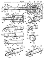
- Fig. 1 is a broken side view, partly in section, of a safety penetrating instrument according to the present invention.
- Fig. 2 is a view section taken along line 2-2 of Fig. 1 showing the hub and locking mechanism.
- Fig. 3 is a broken perspective view of the distal end of the safety penetrating instrument of Fig. 1 in a retracted position.
- Fig. 4 is a broken perspective view of a modification of the distal end of the safety according to the present invention.
- Fig. 5 is a broken side view, partly in section, of another modification of the distal end of the safety penetrating instrument according to the present invention.
- Figs. 6, 7 and 8 are broken top, bottom and end views, respectively, of the safety penetrating instrument of Fig. 5.
- Figs. 9 and 10 are broken views of a further modification of the distal end of the safety penetrating instrument according to the present invention in extended and retracted positions respectively.
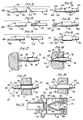
- Fig. 11 is a broken, exploded view of another embodiment of the safety penetrating instrument according to the present invention.
- Fig. 12 is a broken side view of the safety penetrating instrument of Fig. 11 with the safety probe in an extended position.
- Fig. 13 is a broken, exploded view of another embodiment of the safety penetrating instrument according to the present invention.
- Fig. 14 is a broken side view of the modified safety penetrating instrument of Fig. 13 with the safety probe in an extended position.
- Fig. 15 is a broken, exploded view of another embodiment of the safety penetrating instrument according to the present invention.
- Fig. 16 is a broken side view of the safety penetrating instrument of Fig. 15 with the safety probe in an extended position.
- Figs. 17, 18 and 19 are broken views illustrating use of the safety penetrating instrument of Fig. 1.
- Fig. 20 is a broken view of a modification of the portal sleeve of the safety penetrating instrument according to the present invention.
- Fig. 21 is a broken sectional view of a modification of the safety penetrating instrument according to the present invention.
- a safety penetrating instrument 30 is illustrated in Fig. 1 and includes an elongate, tubular needle 32, a safety probe 34 movably disposed concentrically within needle 32, an elongate, tubular portal sleeve 36 concentrically disposed around needle 32, a hub 38 mounting needle 32 and safety probe 34 and a housing 40 mounting portal sleeve 36.
- the hub 38 can be latched to housing 40 with the use of any suitable releasable mechanism, such as ball detents 42, allowing the hub to be removed from the housing withdrawing the needle and safety probe from the portal sleeve.
- the safety penetrating instrument 30 may be considered to be formed of a portal unit and a penetrating unit, the portal unit including portal sleeve 36 and housing 40 and the penetrating unit including needle 32, safety probe 34 and hub 38.
- Needle 32 is preferably made of a cylindrical length of stainless steel having a diameter and wall thickness dependent upon the procedure to be formed and the anatomical cavity to be penetrated.
- the needle has a distal end 42 terminating at a peripheral edge 44 disposed in a plane positioned at an acute angle relative to the longitudinal axis of the needle to define a sharp, tissue penetrating tip or point 46 at a leading or front edge and, proximally spaced from the leading edge, a trailing or rear edge 48.
- the wall of the needle is ground at an angle, as shown at 50, to terminate at sharp tip 46 such that tip 46 is aligned with the inner surface of the cylindrical needle wall.
- Needle 32 has a proximal end 51 secured to a front wall 52 of hub 38 by any suitable means, such as threads 54 or cement.
- Hub 38 is preferably made of plastic to reduce cost and has an external configuration to cooperate with housing 40 to be easily grasped with one hand for use in penetrating tissue.
- Hub 38 is substantially rectangular in cross-section and includes, as best shown in Figs. 1 and 2, four side walls extending from front wall 52 to a rear wall 56 to provide a rearwardly flared outer profile with one side wall, indicated at 58, having a slot 60 therein.
- Rear wall 56 has a recess therein receiving and protecting a valve 62 which is shown as a flap valve but could be any type of valve, such as a stop cock.
- a tube 64 has a flange 65 threadedly secured to rear wall 56 adjacent valve 62 such that valve 62 controls flow therethrough, and tube 64 extends through hub 38 to be slidably received in safety probe 34.
- Safety probe 34 is preferably made from a cylindrical length of a rigid or flexible material, such as stainless steel or plastic dependent upon use of the safety penetrating instrument, and has a distal end 66 with a configuration to protect sharp tip 46 of needle 32 in an extended position as shown in Fig. 1.
- the distal end 66 has a hole 67 therein and an end surface 68 disposed at an acute angle to the longitudinal axis of needle 32 substantially the same as the acute angle of the needle peripheral edge 44. In this manner, the peripheral edge 44 of the distal end of needle 32 and the distal end surface 68 of safety probe 34 will be maintained in substantially parallel relation when the safety probe is in the extended position and will be positioned in substantially the same plane when the safety probe is in the retracted position as illustrated in Fig. 3.
- End surface 68 has a rounded, partially spherical or bulging, dome-shaped configuration; however, dependent upon use of the safety penetrating instrument, the end surface can be substantially flat so long as sharp surfaces are avoided.
- the sharp tip 46 is positioned in abutment with the lateral wall of the safety probe in the extended position to be well protected and unexposed.
- the safety probe has a proximal end 70 disposed within hub 38 carrying spaced annular ribs 72 and 74 between which is rotatably mounted a member or plate 76 having a pin 78 threadedly secured thereto and extending through slot 60, the pin 78 having a spherical end or knob to be easily grasped.
- a helical spring 80 is mounted in compression between plate 76 and the end wall of hub 38, and the spring 80 has longitudinally extending ends received in apertures in plate 76 and flange 65 such that the spring can be wound in torsion to bias the plate and the pin 78 carried thereby in a clockwise direction looking at the proximal end of the safety penetration instrument or upwardly looking at Fig. 1.
- the slot 60 formed in hub 38 has a longitudinal portion 82 aligned in parallel relation with the longitudinal axis of the needle, a distal transverse portion 84 and a proximal transverse portion 86 having a recess 88 at the end thereof extending parallel with the longitudinal slot portion 82. If desired, for purposes to be explained hereinafter, the proximal slot portion can extend in the same direction as the distal slot portion as shown in dashed lines at 90.
- Portal sleeve 36 is preferably made of a cylindrical length of stainless steel or other suitable, medically acceptable, plastic or metal material and can be rigid or flexible and transparent or opaque.
- the portal sleeve has a distal end 94 terminating at a peripheral edge 96 disposed in substantial alignment with or forward of the trailing edge 48 of the needle such that the distal ends of the needle and the portal sleeve present a substantially smooth profile to facilitate tissue penetration.
- the distal end 94 has a tapered, conical portion 98 disposed at the same acute angle to the longitudinal axis of needle 32 as the angle of the peripheral edge 44 of the needle such that the portal sleeve 36 smoothly follows the needle during tissue penetration.
- the portal sleeve 36 has a threaded proximal end 100 removably received in a threaded nipple 102 extending from a front wall 104 of housing 40.
- Housing 40 is preferably made of plastic and has a rectangular configuration in cross-section corresponding to the cross-sectional configuration of hub 38 with a flared external profile adjacent front wall 104 to facilitate grasping during use.
- a valve assembly 106 is mounted in housing 40 to control flow through the portal sleeve once the penetrating unit is removed therefrom.
- the valve assembly can have any acceptable configuration and, as shown, includes a flapper valve member 108 spring-biased to a closed position against an annular valve seat formed by the distal end of a cylindrical tube 110 secured in a threaded plate 112 pivotally mounting the valve member and threadedly secured in an annular threaded wall portion of housing 40.
- An adapter plug 114 is mounted on the proximal end of tube 110 and is integrally constructed of a flexible resilient material, such as Teflon, silicone rubber or plastic. The adapter plug 114, as also shown in Fig.
- flange portion 116 has a thick flange portion 116 with an annular recess 117 therein for receiving the proximal end of tube 110 and a cylindrical inner wall 118 extending from an inner edge of a central aperture 119 in the flange 116 to be snugly received within tube 110.
- the thickness of wall 118 is dependent upon the size of the instrument to be inserted through the portal sleeve such that, if instruments smaller than the penetrating unit are to be introduced into the body after the penetrating unit is withdrawn from the portal sleeve, the adapter plug 114 is removed from the proximal end of tube 110 and another adapter sleeve is inserted therefor having an inner cylindrical wall of greater thickness to engage the smaller instruments along the length of the wall.
- the diameter of the inner wall 118 and the thickness thereof will vary dependent upon the diameter of instruments passing through the portal unit, and the inner diameter will be substantially the same as or slightly less than the outer diameter of the instrument passing therethrough to produce a seal there- around extending along the length of the wall.
- an effective seal can be produced for instruments varying greatly in size, for example from 2mm to 12mm.
- the safety probe 34 can be inserted in the proximal end of the hub and through the needle along with the tube 64 and spring 64. With the plate 76 in place, the pin 78 is passed through the slot 60 and screwed into the plate such that the plate cannot rotate within the hub.
- the tube 64 is twisted clockwise to create torsion in the spring to rotationally bias plate 76 and pin 78 clockwise as noted above.
- the tube flange 65 is then screwed into the end wall 56 of the hub to place the safety penetrating instrument 30 in the condition shown in Fig. 2 with spring 80 biasing the safety probe distally such that the distal end 66 is normally in the extended position shown in Fig. 1 protecting the sharp tip 46 of the needle.
- the pin 78 will be, accordingly, biased distally along longitudinal portion 82 of slot 60 to a position adjacent distal transverse portion 84 and be biased into transverse slot portion 84 due to the torsional bias from the spring to releasably lock the safety probe in the extended position.
- the penetrating unit formed by the needle 32, the safety probe 34 and the hub 38 is then combined with the portal unit by passing needle 32 through the central aperture in adapter plug 114 and through housing 40 and portal sleeve 36 moving valve member 108 away from the valve seat on the distal end of tube 110.
- a cylindrical skirt 119 extending from hub front wall 52 will be disposed within the open proximal end of the housing, and the detents 42 will hold the hub in position with respect to the housing.
- the distal peripheral edge 96 will be disposed substantially in alignment with the trailing edge 48 of the needle distal end to facilitate tissue penetration by the safety penetrating instrument 30.
- the distal end of the portal sleeve be positioned at least in alignment with the trailing edge of the needle or forward thereof. If the distal end of the portal sleeve is proximally spaced from the trailing edge of the needle, tissue penetration will be more difficult with increased trauma. Accordingly, the positioning of the distal ends of the needle, the safety probe and the portal sleeve are extremely important in facilitating tissue penetration with minimal tissue resistance and trauma.
- the distal end of the safety penetrating instrument 30 is illustrated in Fig. 3 with the safety probe in the retracted position, and it can be seen therefrom that the end surface 68 of the distal end of the safety probe is in substantially the same plane as the peripheral edge 44 at the distal end 42 of the needle 32 with the distal end of the safety probe substantially filling the open distal end of the needle to reduce gaps between the distal ends of the needle and the safety probe and the trapping or jamming of tissue therebetween.
- FIG. 4 A modification of the safety probe 34 is illustrated in Fig. 4 wherein the safety probe has a distal end 120 having an end surface 122 angled similar to end surface 68 in Fig. 3.
- a protruding peripheral rim 124 extends from end surface 122 to expand laterally in all directions when the safety probe is in the extended position and contract to completely fill the open distal end of the needle when the safety probe is in the retracted position. In this manner, the reduced gaps between the distal ends of the needle and safety in the embodiment of Fig. 3 are prevented to eliminate trapping or jamming of tissue.
- a modification of safety penetrating instrument 30 is illustrated in Figs. 5, 6, 7 and 8 with the primary differences being that the sharp point 46 at the distal end of the needle 32 is not angularly ground such that the sharp tip is aligned with the outer surface of the wall of the needle as in conventional hypodermic needles and that the safety probe 34 has a groove or recess 126 formed therein such that the distal end is closed with the exception of a lateral hole 128.
- the distal end of the safety needle has a specific configuration to protect the sharp needle tip 46 due to the needle tip being received in groove 126 when the safety probe is in the extended position and further due to the distal end being bent or angled, as best shown in Fig.
- the safety probe By constructing the safety probe of a flexible material, such as plastic, the safety probe will straighten or realign when moved to the retracted position and, when moved to the extended position, will return to the bent or angled configuration forming recess 130 for receiving the needle tip.
- the distal end of the safety probe is angled or bent as described with respect to the previous embodiment and, additionally, the distal end is split or slotted to form opposing parts 132 and 134.
- the split or slot 136 terminates at radiused ends 138 such that the parts 132 and 134 are biased away from each other to produce an expanded state when the safety probe is in the extended position.
- Use of the safety penetrating instrument of Fig. 9 for grasping and/or cutting tissue, for example for biopsy, is illustrated in Fig. 10 wherein it can be seen that tissue 140 can be grasped by placing the safety probe adjacent the tissue in the expanded state, as shown in Fig.
- the safety probe can be releasably locked in the retracted position by moving the pin 78 into transverse slot portion 86 and, into the recess 88 formed therein to prevent the pin from returning to its normally biased position.
- the safety probe is preferably made of stainless steel and the distal edges are inwardly sharp to cut and grasp the tissue to be taken for biopsy.
- FIG. 11 and 12 Another embodiment of a safety penetrating instrument according to the present invention is illustrated in Figs. 11 and 12 wherein an elongate tubular needle 142 has a distal end 143 with an open, acutely angled end defining a peripheral edge 144 with a portion 146 of the distal end curving toward the longitudinal axis of the needle to terminate at a sharp distal tip 148 laterally or radially displaced from the wall of the needle.
- a safety probe 150 has a distal end 152 with a curvature to protrude over sharp tip 148 when the safety probe is in the extended position as illustrated in Fig. 12.
- the distal end 152 has a bulbus configuration with an aperture 154 therein to permit communication through the safety penetrating instrument for injection or evacuation of fluid. While a smoothly curving configuration can provide protection for the sharp needle tip 148, a recess in the form of a concave portion 155 shown in dashed lines can be provided in the safety probe distal end to further prevent
- FIG. 13 and 14 Another embodiment of a safety penetrating instrument according to the present invention is illustrated in Figs. 13 and 14 wherein an elongate tubular needle 156 has a curved distal portion 158 extending less then portion 146 shown in Fig. 11 to terminate at a sharp tip 160.
- a safety probe 162 has a longitudinal groove 164 therein to form a recess receiving the sharp needle tip 160 at the distal end of the needle as illustrated in Fig. 14.
- the distal end of the safety probe has a large hole 166 and a plurality of small holes 168 therein.
- a safety penetrating instrument according to the present invention illustrated Figs. 15 and 16 is similar to that illustrated in Figs. 13 and 14 with the exception that the safety probe 170 has an annular open distal end 172 allowing communication directly therethrough.
- the round peripheral edge of distal end 172 is interrupted to form a recess in the form of a slot or groove 174 for receiving the sharp needle tip 166.
- proximal portions can be formed by any suitable cooperating structure and are particularly advantageous when utilized with the locking and spring biasing mechanism illustrated in Figs. 1 and 2.
- various features from the disclosed embodiments can be combined dependent upon the procedure to be performed with a particular safety penetrating instrument.
- the safety probe cannot move proximally within needle 32 thereby assuring that the sharp tip 46 is protected to prevent inadvertent contact.
- the blunt end surface 68 is positioned in abutment with the tissue T to be penetrated as illustrated in Fig. 17, and a finger is utilized to manually move pin 78 counter-clockwise against the torsional bias of spring 80 to be aligned with the longitudinal portion 82 of slot 60.
- the sharp needle tip is protected by being received in the recess.
- the angle of the end surface of the safety probe distal end corresponds with the angle of the needle distal end, the distal ends of the needle and the safety probe will be disposed in substantially the same plane to reduce tissue resistance during penetrating and produce a minimum gap between the safety probe and the needle to minimize trapping or jamming of tissue therebetween.
- the reduction in tissue resistance is further enhanced by the positioning of the peripheral distal edge of the portal sleeve substantially in alignment with the trailing edge of the needle distal end. Protection of the sharp needle tip is particularly effective where the distal end of the needle is ground as shown at 50 in that the sharp needle tip will abut the distal end of the safety probe when the safety probe is in the extended position.
- the surgeon can selectively release the safety probe from the extended position by moving pin 78 counter-clockwise to be aligned with longitudinal slot portion 82. If the protection provided by the safety probe is not required or desired for further procedures, the pin 78 can be moved into recess 88 of proximal transverse slot portion 86 to releasably lock the safety probe in the retracted position or a position further withdrawn into needle 32 dependent upon the longitudinal position of transverse slot portion 86. If proximal transverse slot portion 90 is provided, the safety probe will automatically lock in the retracted position when pin 78 is aligned with slot portion 90 due to the rotational bias from spring 80. If slot portion 90 is positioned proximally of pin 78 when the safety probe is in the retracted position, the safety probe will not automatically lock during use but rather the pin will have to be manually pulled back to alignment with slot portion 90 to lock the safety probe within the needle.
- safety probe 34 does not rotate therewith to maintain alignment with needle 32, and various index configurations to maintain rotational alignment between the safety probe and the needle can be used, if desired.
- the safety probe can be splined with the needle or with tube 64.
- the safety penetrating instrument can be used to permit flow of fluids into or out of the cavity since communication is established through hole 67 and the body of the safety probe 34 and through tube 64 and valve 62.
- the safety penetrating instrument 30 can be used, for example, to create a pneumoperitoneum.
- the portal sleeve 36 can be left in place by withdrawing the penetrating unit from the portal unit; and, once the penetrating unit is withdrawn, valve member 108 will engage the valve seat formed by the distal edge of tube 110 to prevent fluid flow through the portal formed by the portal sleeve 36 and housing 40. If it is desired to then insert an instrument having a diameter less than the diameter of needle 32, adapter plug 112 is removed from the proximal end of tube 110 and replaced with an adapter plug having a central aperture and tubular passage formed by the inner wall 118 of a diameter corresponding to the smaller instrument to be inserted.
- the portal sleeve can have a normal, non-linear configuration such that, once penetration is completed and the penetrating unit is withdrawn from the portal unit, the portal sleeve will return to the non-linear configuration.
- the portal sleeve is shown in dashed lines in Fig. 19 as having a curved configuration 181 to which the portal sleeve returns when the needle and safety probe are withdrawn.
- FIG. 20 A modification of the portal sleeve of the safety penetrating instrument is shown in Fig. 20 wherein the portal sleeve 36 has a distal end with a peripheral edge 176 obliquely arranged at an acute angle relative to the longitudinal axis of the needle with a rounded leading edge 178 disposed in longitudinal alignment with sharp needle tip 46 and a trailing edge 180 in alignment with the trailing edge 48 of the peripheral edge at the needle distal end.
- the modification of Fig. 20 has the advantages of assuring that at least the leading edge of the portal sleeve has penetrated the anatomical wall when the safety probe returns to the extended position and of facilitating tissue penetration since the distal end of the portal sleeve gradually enters the tissue following the needle.
- valve assembly 106 is formed of a member 182 having an annular base 184 sealingly engaged with the distal end of tube 110 and a plurality of spaced, spreadable, legs 186 extending distally from base 184 to produce a normally conical configuration.
- the member 182 is preferably made of unitary construction of a material facilitating movement of medical instruments therethrough and allowing legs 186 to flex, such as a plastic like nylon.
- the legs 186 are concentrically disposed around annular base 184 and the central opening therethrough and are slightly spaced from each other and terminate at curved relief recesses (not shown).
- a conical, stretchable sleeve or membrane 188 preferably made of a rubber-like material such as silicone, has a configuration to tightly fit over legs 186 such that the sleeve and legs are normally biased to a closed position at the apex to prevent passage of fluids through the valve assembly.
- the valve assembly is normally biased to a closed position due to the elastic force of conical sleeve 188 around legs 186; and, when a surgical instrument is inserted through the portal unit, the surgical instrument will cause legs 186 to flex outwardly stretching conical sleeve 188 such that conical sleeve acts as a seal to prevent passage of fluids thereby and tightly engages the surgical instrument in the gaps where the legs are spread apart.
- the valve assembly provides a passage of variable size to accommodate surgical instruments of various sizes passing therethrough in that the legs and conical sleeve contract to sealingly engage the surgical instrument regardless of the diameter thereof, and, in combination with adapter plug 114, an excellent seal through the portal unit is established.
- portal sleeve 36 is resiliently, movably secured to the housing 40 to allow the portal sleeve to be slightly moved with respect to the housing and the penetrating unit against a spring bias.
- the proximal and 190 of the portal sleeve slidably received in a nipple 192 which is threadedly secured to a front wall 193 of housing 40, and a seal is provided by one or more O-rings 194.
- the proximal end 190 carries an annular end collar 196 limiting distal movement of the portal sleeve by abutment with the front wall portion of housing 40 formed by nipple 192.
- a helical spring 198 is mounted in compression between collar 196 and an annular shoulder 200 fixed in housing 40 such that the portal sleeve is distally biased. During penetration of tissue, the portal sleeve can move proximally against the bias of spring 198 to facilitate penetration during difficult procedures.
- the spring 80 is not wound during assembly such that pin 78 is not rotationally biased. Accordingly, after spring 80 returns the safety probe 34 to the extended position when the force on the safety probe distal end from tissue resistance is removed, the pin will not enter transverse slot portion 84, and the safety probe will not be locked in the extended position. Thus, the surgeon has the option of locking the safety probe in the extended position by manually moving pin 78 into transverse slot portion 84 or allowing the safety probe to be free to move proximally by not moving pin 78 into transverse slot portion 84.
- Safety penetrating instruments formed of an elongate tubular needle with a safety probe having a distal end configured to define a protective recess for receiving the sharp tip of the needle in the extended position are particularly advantageous for safely introducing a portal sleeve into veins or arteries with reduction of the chances of developing hematoma.
- the safety penetrating instrument utilizes an elongate tubular needle with an acutely angled distal end including a portion curving toward the longitudinal axis of the needle to terminate at a sharp tip radially inwardly spaced from the wall of the needle and a safety probe having a distal end configured to protrude over the sharp tip in the extended position, rotational penetration can be safely performed to introduce a portal sleeve into the body.
- the distal end portion of the needle can be curved inwardly to any desired extent from a slight curve, as shown in Figs. 11, 13 and 15, to a curve through almost the entire diameter of the needle to produce a sharp, spoon-like shape with the distal end of the safety probe configured to protrude over the sharp tip by providing a protective recess therein or by bending in the same direction as the curvature of the curved position.
- the safety penetrating instrument of the present invention can be used for penetrating cavity walls in a manner similar to presently used trocars and can have various diameters ranging from 2mm to 12mm.
- the use of a tubular needle in the safety penetrating instrument of the present invention has the advantages of permitting placement of the portal sleeve or cannula in small or large cavities to provide a portal communicating therewith, of permitting a scooping movement during penetration to get through the wall without compressing the cavity when the needles of Figs. 11, 13 and 15 are used, of being useful for first, second or other puncture techniques, of permitting penetration of a second cavity wall after penetration of a first cavity wall and of allowing the performance of additional procedural steps, such as suction, cutting, biopsy and aspiration.
- the safety probe can be made of metal, such as stainless steel, rubber or plastic, with materials having good sliding characteristics, such as Teflon, being preferred. While the safety probes are advantageously hollow or tubular to allow passage of fluids therethrough, the safety probes can be solid if desired.
- safety penetrating instruments provide increased protection of the sharp tip of a tubular needle while also facilitating use and tip exposure after penetration of an anatomical cavity by providing selective, releasable locking positions for the safety probe. It will be appreciated that the safety penetrating instrument of the present invention is useful to penetrate tissue in various portions of the body, and "anatomical cavity" as used herein refers to any area of the body requiring penetration of tissue for access.
Abstract
Description
- The present invention pertains to surgical penetrating instruments and, more particularly, to safety surgical penetrating instruments having tubular needles for penetrating tissue and safety probes for protecting the sharp tips of the needles.
- Surgical penetrating instruments are widely used in surgical procedures to gain access to anatomical cavities ranging in size from the abdomen to small blood vessels, such as veins and arteries, epidural, pleural and subarachnoid spaces, heart ventricles and spinal and synovial cavities. Such surgical penetrating instruments include a penetrating member or implement having a sharp tip or point to pierce or penetrate the tissue forming the cavity wall, and the force required to penetrate the cavity wall is dependent upon the type and thickness of the tissue of the wall. Once the wall is penetrated, it is desirable to protect the sharp tip of the penetrating member to prevent inadvertent contact with tissue in or forming the cavity, and a particular problem exists where substantial force is required to penetrate the cavity wall in that, once penetration is achieved, the lack of tissue resistance can result in the sharp tip travelling too far into the cavity and injuring adjacent tissue.
- Safety penetrating instruments including a safety probe biased to extend beyond the sharp tip of a penetrating member have become widely accepted for use in penetrating anatomical cavities. For example, the Verres needle, commonly used to create a pneumoperitoneum, has a spring-loaded inner member disposed within a tubular needle. U.S. Patents No. 1,527,291 to Zorraquin, No. 2,623,521 to Shaw and No. 2,630,803 to Baran are exemplary of safety penetrating instruments with a spring-loaded inner member disposed in a needle, while U.S. Patent No. 4,254,762 to Yoon shows an endoscope spring-biased in a hollow needle. Safety trocars having a spring-biased protective shield disposed between an outer sleeve and an inner trocar are marketed by Ethicon, Inc. as the Endopath and by United States Surgical Corp. as the Surgiport. U.S. Patents No. 4,535,773 to Yoon and No. 4,654,030 to Moll et al are exemplary of such safety trocars. German Offenlegungsschrift 2,544,262 discloses an intrauterine catheter including a tube having a distal sharp point, a spring-biased blunt member in the tube distal end and a hose or catheter slidable over the tube.
- While the prior art safety penetrating instruments are widely used, they suffer from many disadvantages when used in the procedures for which they are presently recommended; and, additionally, prior art safety penetrating instruments cannot be used in many procedures for which safety of penetration is highly desirable. One of the disadvantages of prior art surgical penetrating instruments is that, when the penetrating member is a tubular needle with an acutely angled distal end, the sharp tip is not well protected and is still at least partially exposed when the safety probe is extended to the protective position such that use in penetrating small of narrow anatomical cavities is not safe, while another disadvantage is that the safety probe cannot be locked in an extended, needle tip protecting position. A further disadvantage is that the sharp tip of the needle cannot be selectively exposed for effective use in further penetration of tissue after a cavity wall is initially penetrated.
- Accordingly, it is a primary object of the present invention to overcome the above mentioned disadvantages of the prior art by utilizing a tubular needle with a safety probe movable therein in a safety penetrating instrument including a portal sleeve thereby increasing safety and efficacy in a wide range of surgical procedures.
- Another object of the present invention is to position the distal edge of a portal sleeve in alignment with or forward of the trailing edge of an angled open end of a needle in a safety penetrating instrument having a safety probe movable in the needle such that the needle and portal sleeve present a substantially smooth profile for tissue penetration.
- A further object is to optionally allow locking of a safety probe in an extended position in a needle of a safety penetrating instrument including a portal sleeve or to allow the safety probe to move proximally from the extended position.
- Another object of the present invention is to utilize a tubular needle to position a portal sleeve through a cavity wall with the sharp tip of the needle received in a protective recess in a safety probe to minimize exposure of the sharp tip both after penetration of tissue and during handling by medical personnel thereby reducing the opportunity for contact and/or piercing of tissue inadvertently.
- A further object of the present invention is to align an angled distal end surface of a safety probe with an angled sharp distal end of a tubular needle within a portal sleeve such that the distal ends of the safety probe and the needle are in substantially the same plane during tissue penetration to facilitate placement of the portal sleeve.
- An additional object of the present invention is to utilize a safety probe in a tubular needle having an open distal end with a portion curving toward the longitudinal axis of the needle to terminate at a sharp tip such that, in an extended position, the distal end of the safety probe protrudes over the sharp tip of the needle.
- The present invention has another object in that a safety probe movable relative to an elongate penetrating needle within a portal sleeve is biased toward an extended position and can be selectively, releasably locked in a retracted position such that the safety probe can be disabled prior to or after penetration of a cavity wall.
- Yet another object of the present invention is to construct a safety penetrating instrument such that a distally biased safety probe can be manually pulled proximally toward a retracted position to expose the sharp distal end of a tubular needle without requiring a force applied to the distal end of the safety probe from tissue contact.
- A further object of the present invention is to utilize a safety probe having an expandable distal end in a safety penetrating instrument including a portal sleeve such that in an extended position the distal end of the safety probe is in an expanded state protecting the sharp tip of a tubular needle while in a retracted position the distal end of the safety probe is in a contracted state substantially filling the needle. The distal end of the safety probe can be slotted or split to permit further use for grasping tissue, such as for biopsy.
- The present invention has an additional object in the use of a pin and slot mechanism to provide selective locking of a safety probe distally biased relative to a penetrating needle, the pin extending externally of a hub to form a handle graspable by a surgeon to selectively move the safety probe. When the pin is in a longitudinal portion of the slot, the safety probe can be moved against the bias; and, when the pin is in proximal or distal transverse portions of the slot at opposite ends of the longitudinal portion, the safety probe is releasably locked in retracted and extended positions, respectively.
- Some of the advantages of the present invention over the prior art are that very small cavities, such as veins, arteries, pleural spaces, spinal canals and subarachnoid and epidural spaces, can be safely penetrated to establish a portal in communication therewith, the chance of developing a hematoma during penetration of a vein or artery is substantially reduced, second puncture endoscopic procedures are facilitated, safe penetration is achieved while permitting injection or evacuation of fluids, penetration into additional tissue after penetration of a cavity wall can be accomplished with a single instrument, such as into a cystic cavity or soft organ structure (e.g., ovarian cyst penetration or liver tissue biopsy), a single puncture can be used for both insufflation and forming an endoscopic portal thereby simplifying procedures such as laparoscopies, and safety penetrating instruments according to the present invention can be inexpensively manufactured to permit universal use in place of presently used penetrating members, such as trocars and tubular needles.
- The present invention is generally characterized in a safety penetrating instrument including a tubular needle having a distal end with a sharp tip, a safety probe movable within the needle between an extended position protecting the needle tip and a retracted position exposing the needle tip and biased toward the extended position, a hub receiving the proximal ends of the needle and the safety probe, and a portal sleeve surrounding the needle to establish communication with an anatomical cavity with penetration by the needle. The needle distal end has a leading edge defining the sharp tip and a trailing edge, and the distal edge of the portal sleeve is disposed in substantial alignment with or forward of the trailing edge of the needle distal end. A locking mechanism automatically locks the safety probe in the extended position after the safety probe is returned thereto or can optionally allow locking of the safety probe or allow proximal movement of, the safety probe after return to the extended position. The locking mechanism also provides selective locking of the safety probe in the retracted position. The distal end of the safety probe has an angled end surface such that, in the retracted position, the angled end surface of the safety probe is in substantially the same plane and the angled distal peripheral edge of the needle.
- Other objects and advantages of the present invention will become apparent from the following description of the preferred embodiments taken in conjunction with the accompanying drawings wherein like parts in each of the several figures are identified by the same reference characters.
- Fig. 1 is a broken side view, partly in section, of a safety penetrating instrument according to the present invention.
- Fig. 2 is a view section taken along line 2-2 of Fig. 1 showing the hub and locking mechanism.
- Fig. 3 is a broken perspective view of the distal end of the safety penetrating instrument of Fig. 1 in a retracted position.
- Fig. 4 is a broken perspective view of a modification of the distal end of the safety according to the present invention.
- Fig. 5 is a broken side view, partly in section, of another modification of the distal end of the safety penetrating instrument according to the present invention.
- Figs. 6, 7 and 8 are broken top, bottom and end views, respectively, of the safety penetrating instrument of Fig. 5.
- Figs. 9 and 10 are broken views of a further modification of the distal end of the safety penetrating instrument according to the present invention in extended and retracted positions respectively.
- Fig. 11 is a broken, exploded view of another embodiment of the safety penetrating instrument according to the present invention.
- Fig. 12 is a broken side view of the safety penetrating instrument of Fig. 11 with the safety probe in an extended position.
- Fig. 13 is a broken, exploded view of another embodiment of the safety penetrating instrument according to the present invention.
- Fig. 14 is a broken side view of the modified safety penetrating instrument of Fig. 13 with the safety probe in an extended position.
- Fig. 15 is a broken, exploded view of another embodiment of the safety penetrating instrument according to the present invention.
- Fig. 16 is a broken side view of the safety penetrating instrument of Fig. 15 with the safety probe in an extended position.
- Figs. 17, 18 and 19 are broken views illustrating use of the safety penetrating instrument of Fig. 1.
- Fig. 20 is a broken view of a modification of the portal sleeve of the safety penetrating instrument according to the present invention.
- Fig. 21 is a broken sectional view of a modification of the safety penetrating instrument according to the present invention.
- A
safety penetrating instrument 30 according to the present invention is illustrated in Fig. 1 and includes an elongate,tubular needle 32, asafety probe 34 movably disposed concentrically withinneedle 32, an elongate,tubular portal sleeve 36 concentrically disposed aroundneedle 32, ahub 38mounting needle 32 andsafety probe 34 and ahousing 40mounting portal sleeve 36. Thehub 38 can be latched tohousing 40 with the use of any suitable releasable mechanism, such asball detents 42, allowing the hub to be removed from the housing withdrawing the needle and safety probe from the portal sleeve. Accordingly, thesafety penetrating instrument 30 may be considered to be formed of a portal unit and a penetrating unit, the portal unit includingportal sleeve 36 andhousing 40 and the penetratingunit including needle 32,safety probe 34 andhub 38. -
Needle 32 is preferably made of a cylindrical length of stainless steel having a diameter and wall thickness dependent upon the procedure to be formed and the anatomical cavity to be penetrated. The needle has adistal end 42 terminating at aperipheral edge 44 disposed in a plane positioned at an acute angle relative to the longitudinal axis of the needle to define a sharp, tissue penetrating tip orpoint 46 at a leading or front edge and, proximally spaced from the leading edge, a trailing orrear edge 48. At the leading edge, the wall of the needle is ground at an angle, as shown at 50, to terminate atsharp tip 46 such thattip 46 is aligned with the inner surface of the cylindrical needle wall.Needle 32 has aproximal end 51 secured to afront wall 52 ofhub 38 by any suitable means, such asthreads 54 or cement. - Hub 38 is preferably made of plastic to reduce cost and has an external configuration to cooperate with
housing 40 to be easily grasped with one hand for use in penetrating tissue.Hub 38 is substantially rectangular in cross-section and includes, as best shown in Figs. 1 and 2, four side walls extending fromfront wall 52 to arear wall 56 to provide a rearwardly flared outer profile with one side wall, indicated at 58, having aslot 60 therein.Rear wall 56 has a recess therein receiving and protecting avalve 62 which is shown as a flap valve but could be any type of valve, such as a stop cock. Atube 64 has a flange 65 threadedly secured torear wall 56adjacent valve 62 such thatvalve 62 controls flow therethrough, andtube 64 extends throughhub 38 to be slidably received insafety probe 34. -
Safety probe 34 is preferably made from a cylindrical length of a rigid or flexible material, such as stainless steel or plastic dependent upon use of the safety penetrating instrument, and has adistal end 66 with a configuration to protectsharp tip 46 ofneedle 32 in an extended position as shown in Fig. 1. Thedistal end 66 has ahole 67 therein and anend surface 68 disposed at an acute angle to the longitudinal axis ofneedle 32 substantially the same as the acute angle of the needleperipheral edge 44. In this manner, theperipheral edge 44 of the distal end ofneedle 32 and thedistal end surface 68 ofsafety probe 34 will be maintained in substantially parallel relation when the safety probe is in the extended position and will be positioned in substantially the same plane when the safety probe is in the retracted position as illustrated in Fig. 3.End surface 68 has a rounded, partially spherical or bulging, dome-shaped configuration; however, dependent upon use of the safety penetrating instrument, the end surface can be substantially flat so long as sharp surfaces are avoided. By grinding the distal end of the needle, thesharp tip 46 is positioned in abutment with the lateral wall of the safety probe in the extended position to be well protected and unexposed. As best shown in Fig. 2, the safety probe has aproximal end 70 disposed withinhub 38 carrying spacedannular ribs plate 76 having apin 78 threadedly secured thereto and extending throughslot 60, thepin 78 having a spherical end or knob to be easily grasped. Ahelical spring 80 is mounted in compression betweenplate 76 and the end wall ofhub 38, and thespring 80 has longitudinally extending ends received in apertures inplate 76 and flange 65 such that the spring can be wound in torsion to bias the plate and thepin 78 carried thereby in a clockwise direction looking at the proximal end of the safety penetration instrument or upwardly looking at Fig. 1. Theslot 60 formed inhub 38 has alongitudinal portion 82 aligned in parallel relation with the longitudinal axis of the needle, a distaltransverse portion 84 and a proximaltransverse portion 86 having arecess 88 at the end thereof extending parallel with thelongitudinal slot portion 82. If desired, for purposes to be explained hereinafter, the proximal slot portion can extend in the same direction as the distal slot portion as shown in dashed lines at 90. -
Portal sleeve 36 is preferably made of a cylindrical length of stainless steel or other suitable, medically acceptable, plastic or metal material and can be rigid or flexible and transparent or opaque. The portal sleeve has adistal end 94 terminating at aperipheral edge 96 disposed in substantial alignment with or forward of the trailingedge 48 of the needle such that the distal ends of the needle and the portal sleeve present a substantially smooth profile to facilitate tissue penetration. Thedistal end 94 has a tapered,conical portion 98 disposed at the same acute angle to the longitudinal axis ofneedle 32 as the angle of theperipheral edge 44 of the needle such that theportal sleeve 36 smoothly follows the needle during tissue penetration. Theportal sleeve 36 has a threadedproximal end 100 removably received in a threadednipple 102 extending from afront wall 104 ofhousing 40.Housing 40 is preferably made of plastic and has a rectangular configuration in cross-section corresponding to the cross-sectional configuration ofhub 38 with a flared external profile adjacentfront wall 104 to facilitate grasping during use. Avalve assembly 106 is mounted inhousing 40 to control flow through the portal sleeve once the penetrating unit is removed therefrom. The valve assembly can have any acceptable configuration and, as shown, includes aflapper valve member 108 spring-biased to a closed position against an annular valve seat formed by the distal end of acylindrical tube 110 secured in a threadedplate 112 pivotally mounting the valve member and threadedly secured in an annular threaded wall portion ofhousing 40. Anadapter plug 114 is mounted on the proximal end oftube 110 and is integrally constructed of a flexible resilient material, such as Teflon, silicone rubber or plastic. Theadapter plug 114, as also shown in Fig. 21, has athick flange portion 116 with anannular recess 117 therein for receiving the proximal end oftube 110 and a cylindricalinner wall 118 extending from an inner edge of acentral aperture 119 in theflange 116 to be snugly received withintube 110. The thickness ofwall 118 is dependent upon the size of the instrument to be inserted through the portal sleeve such that, if instruments smaller than the penetrating unit are to be introduced into the body after the penetrating unit is withdrawn from the portal sleeve, theadapter plug 114 is removed from the proximal end oftube 110 and another adapter sleeve is inserted therefor having an inner cylindrical wall of greater thickness to engage the smaller instruments along the length of the wall. That is, the diameter of theinner wall 118 and the thickness thereof will vary dependent upon the diameter of instruments passing through the portal unit, and the inner diameter will be substantially the same as or slightly less than the outer diameter of the instrument passing therethrough to produce a seal there- around extending along the length of the wall. By utilizing various size adapter plugs with inner sealing walls to accommodate various size instruments, an effective seal can be produced for instruments varying greatly in size, for example from 2mm to 12mm. In order to assemble thesafety penetrating instrument 30, thesafety probe 34 can be inserted in the proximal end of the hub and through the needle along with thetube 64 andspring 64. With theplate 76 in place, thepin 78 is passed through theslot 60 and screwed into the plate such that the plate cannot rotate within the hub. Thetube 64 is twisted clockwise to create torsion in the spring to rotationallybias plate 76 andpin 78 clockwise as noted above. The tube flange 65 is then screwed into theend wall 56 of the hub to place thesafety penetrating instrument 30 in the condition shown in Fig. 2 withspring 80 biasing the safety probe distally such that thedistal end 66 is normally in the extended position shown in Fig. 1 protecting thesharp tip 46 of the needle. Thepin 78 will be, accordingly, biased distally alonglongitudinal portion 82 ofslot 60 to a position adjacent distaltransverse portion 84 and be biased intotransverse slot portion 84 due to the torsional bias from the spring to releasably lock the safety probe in the extended position. The penetrating unit formed by theneedle 32, thesafety probe 34 and thehub 38 is then combined with the portal unit by passingneedle 32 through the central aperture inadapter plug 114 and throughhousing 40 andportal sleeve 36 movingvalve member 108 away from the valve seat on the distal end oftube 110. With thehub 38 abutting thehousing 40, acylindrical skirt 119 extending fromhub front wall 52 will be disposed within the open proximal end of the housing, and thedetents 42 will hold the hub in position with respect to the housing. In this position, the distalperipheral edge 96 will be disposed substantially in alignment with the trailingedge 48 of the needle distal end to facilitate tissue penetration by thesafety penetrating instrument 30. It is important for smooth tissue penetration that the distal end of the portal sleeve be positioned at least in alignment with the trailing edge of the needle or forward thereof. If the distal end of the portal sleeve is proximally spaced from the trailing edge of the needle, tissue penetration will be more difficult with increased trauma. Accordingly, the positioning of the distal ends of the needle, the safety probe and the portal sleeve are extremely important in facilitating tissue penetration with minimal tissue resistance and trauma. - The distal end of the
safety penetrating instrument 30 is illustrated in Fig. 3 with the safety probe in the retracted position, and it can be seen therefrom that theend surface 68 of the distal end of the safety probe is in substantially the same plane as theperipheral edge 44 at thedistal end 42 of theneedle 32 with the distal end of the safety probe substantially filling the open distal end of the needle to reduce gaps between the distal ends of the needle and the safety probe and the trapping or jamming of tissue therebetween. - A modification of the
safety probe 34 is illustrated in Fig. 4 wherein the safety probe has adistal end 120 having an end surface 122 angled similar to endsurface 68 in Fig. 3. A protrudingperipheral rim 124 extends from end surface 122 to expand laterally in all directions when the safety probe is in the extended position and contract to completely fill the open distal end of the needle when the safety probe is in the retracted position. In this manner, the reduced gaps between the distal ends of the needle and safety in the embodiment of Fig. 3 are prevented to eliminate trapping or jamming of tissue. - A modification of
safety penetrating instrument 30 is illustrated in Figs. 5, 6, 7 and 8 with the primary differences being that thesharp point 46 at the distal end of theneedle 32 is not angularly ground such that the sharp tip is aligned with the outer surface of the wall of the needle as in conventional hypodermic needles and that thesafety probe 34 has a groove orrecess 126 formed therein such that the distal end is closed with the exception of alateral hole 128. The distal end of the safety needle has a specific configuration to protect thesharp needle tip 46 due to the needle tip being received ingroove 126 when the safety probe is in the extended position and further due to the distal end being bent or angled, as best shown in Fig. 5, relative to the longitudinal axis of the needle such that, in the extended position, the bent portion forms asecond recess 130 for receiving thesharp needle tip 46. By constructing the safety probe of a flexible material, such as plastic, the safety probe will straighten or realign when moved to the retracted position and, when moved to the extended position, will return to the bent or angledconfiguration forming recess 130 for receiving the needle tip. - In a further embodiment illustrated in Fig. 9, the distal end of the safety probe is angled or bent as described with respect to the previous embodiment and, additionally, the distal end is split or slotted to form opposing
parts slot 136 terminates at radiused ends 138 such that theparts tissue 140 can be grasped by placing the safety probe adjacent the tissue in the expanded state, as shown in Fig. 9, and, thereafter, pulling the safety probe proximally into the needle by manually graspingpin 78 and moving the pin along thelongitudinal slot portion 82 against the bias ofspring 80. The safety probe can be releasably locked in the retracted position by moving thepin 78 intotransverse slot portion 86 and, into therecess 88 formed therein to prevent the pin from returning to its normally biased position. When the safety penetrating instrument is used for biopsy, the safety probe is preferably made of stainless steel and the distal edges are inwardly sharp to cut and grasp the tissue to be taken for biopsy. - Another embodiment of a safety penetrating instrument according to the present invention is illustrated in Figs. 11 and 12 wherein an elongate
tubular needle 142 has adistal end 143 with an open, acutely angled end defining aperipheral edge 144 with aportion 146 of the distal end curving toward the longitudinal axis of the needle to terminate at a sharpdistal tip 148 laterally or radially displaced from the wall of the needle. Asafety probe 150 has adistal end 152 with a curvature to protrude oversharp tip 148 when the safety probe is in the extended position as illustrated in Fig. 12. Thedistal end 152 has a bulbus configuration with anaperture 154 therein to permit communication through the safety penetrating instrument for injection or evacuation of fluid. While a smoothly curving configuration can provide protection for thesharp needle tip 148, a recess in the form of aconcave portion 155 shown in dashed lines can be provided in the safety probe distal end to further prevent exposure of the sharp needle tip. - Another embodiment of a safety penetrating instrument according to the present invention is illustrated in Figs. 13 and 14 wherein an elongate
tubular needle 156 has a curveddistal portion 158 extending less thenportion 146 shown in Fig. 11 to terminate at asharp tip 160. Asafety probe 162 has alongitudinal groove 164 therein to form a recess receiving thesharp needle tip 160 at the distal end of the needle as illustrated in Fig. 14. The distal end of the safety probe has alarge hole 166 and a plurality ofsmall holes 168 therein. By providing a plurality of holes in the distal end of the safety probe, communication can be maintained even if one of the holes becomes blocked. - The embodiment of a safety penetrating instrument according to the present invention illustrated Figs. 15 and 16 is similar to that illustrated in Figs. 13 and 14 with the exception that the
safety probe 170 has an annular opendistal end 172 allowing communication directly therethrough. The round peripheral edge ofdistal end 172 is interrupted to form a recess in the form of a slot or groove 174 for receiving thesharp needle tip 166. - Only the distal ends of the safety penetrating instrument have been illustrated in Figs. 5 - 16; however, it will be appreciated that the proximal portions can be formed by any suitable cooperating structure and are particularly advantageous when utilized with the locking and spring biasing mechanism illustrated in Figs. 1 and 2. Similarly, various features from the disclosed embodiments can be combined dependent upon the procedure to be performed with a particular safety penetrating instrument.
- In use, it will be appreciated that with the
pin 78 disposed in distaltransverse slot portion 84, the safety probe cannot move proximally withinneedle 32 thereby assuring that thesharp tip 46 is protected to prevent inadvertent contact. When it is desired to penetrate an anatomical cavity, theblunt end surface 68 is positioned in abutment with the tissue T to be penetrated as illustrated in Fig. 17, and a finger is utilized to manually movepin 78 counter-clockwise against the torsional bias ofspring 80 to be aligned with thelongitudinal portion 82 ofslot 60. With thepin 78 in this position, when theend surface 68 of the distal and of the safety probe is forced against the tissue to be penetrated, thesafety probe 34 will move distally against the bias ofspring 80 to the retracted position as illustrated in Figs. 3 and 18, it being noted that when the distal end of the safety probe includes a bent or angled portion, the distal end of the safety probe will straighten out as the safety probe is withdrawn into the needle and additionally that when the distal end has an expanded state in the extended position the distal end will be in a contracted state when the safety probe distal end is moved to the retracted position. With the safety probe in the retracted position, penetration through the tissue with minimal tissue jamming and trapping is accomplished due to the smooth profile of the distal end of the safety penetrating instrument.Pin 78 will not enter proximaltransverse slot portion 86 when the pin is aligned therewith due to the torsional or rotational bias ofspring 80 in the opposite direction; and, thus, once the anatomical wall has been completely penetrated,spring 80 will bias the safety probe distally such that the safety probe returns to the extended position as illustrated in Fig. 19 to protect thesharp tip 46 such that the sharp tip is exposed only during the tissue penetrating step. When the safety probe includes a protective recess such as thegroove 126 in the embodiment of Fig. 5, the bent orangled portions 130 in the embodiments of Figs. 5 and 9, theslot 136 in the embodiment of Fig. 9, theconcavity 154 in the embodiment of Fig. 11 and the grooves orslots - If, after penetration into the anatomical cavity, it is desired to penetrate additional tissue, the surgeon can selectively release the safety probe from the extended position by moving
pin 78 counter-clockwise to be aligned withlongitudinal slot portion 82. If the protection provided by the safety probe is not required or desired for further procedures, thepin 78 can be moved intorecess 88 of proximaltransverse slot portion 86 to releasably lock the safety probe in the retracted position or a position further withdrawn intoneedle 32 dependent upon the longitudinal position oftransverse slot portion 86. If proximaltransverse slot portion 90 is provided, the safety probe will automatically lock in the retracted position whenpin 78 is aligned withslot portion 90 due to the rotational bias fromspring 80. Ifslot portion 90 is positioned proximally ofpin 78 when the safety probe is in the retracted position, the safety probe will not automatically lock during use but rather the pin will have to be manually pulled back to alignment withslot portion 90 to lock the safety probe within the needle. - While
plate 76 andpin 78 can rotate slightly withinhub 38,safety probe 34 does not rotate therewith to maintain alignment withneedle 32, and various index configurations to maintain rotational alignment between the safety probe and the needle can be used, if desired. For example, the safety probe can be splined with the needle or withtube 64. - Once the safety penetrating instrument has penetrated into an anatomical cavity, the safety penetrating instrument can be used to permit flow of fluids into or out of the cavity since communication is established through
hole 67 and the body of thesafety probe 34 and throughtube 64 andvalve 62. In this manner, thesafety penetrating instrument 30 can be used, for example, to create a pneumoperitoneum. - Once the needle has been used to penetrate tissue to the extent desired by the surgeon, the
portal sleeve 36 can be left in place by withdrawing the penetrating unit from the portal unit; and, once the penetrating unit is withdrawn,valve member 108 will engage the valve seat formed by the distal edge oftube 110 to prevent fluid flow through the portal formed by theportal sleeve 36 andhousing 40. If it is desired to then insert an instrument having a diameter less than the diameter ofneedle 32,adapter plug 112 is removed from the proximal end oftube 110 and replaced with an adapter plug having a central aperture and tubular passage formed by theinner wall 118 of a diameter corresponding to the smaller instrument to be inserted. - For procedures where it is desired to gain access to an area of an anatomical cavity substantially offset from the longitudinal axis of the safety penetrating instrument, the portal sleeve can have a normal, non-linear configuration such that, once penetration is completed and the penetrating unit is withdrawn from the portal unit, the portal sleeve will return to the non-linear configuration. For example, the portal sleeve is shown in dashed lines in Fig. 19 as having a
curved configuration 181 to which the portal sleeve returns when the needle and safety probe are withdrawn. - A modification of the portal sleeve of the safety penetrating instrument is shown in Fig. 20 wherein the
portal sleeve 36 has a distal end with aperipheral edge 176 obliquely arranged at an acute angle relative to the longitudinal axis of the needle with a roundedleading edge 178 disposed in longitudinal alignment withsharp needle tip 46 and a trailingedge 180 in alignment with the trailingedge 48 of the peripheral edge at the needle distal end. The modification of Fig. 20 has the advantages of assuring that at least the leading edge of the portal sleeve has penetrated the anatomical wall when the safety probe returns to the extended position and of facilitating tissue penetration since the distal end of the portal sleeve gradually enters the tissue following the needle. - Another modification of the safety penetrating instrument of the present invention is shown in Fig. 21 wherein the
valve assembly 106 is formed of amember 182 having anannular base 184 sealingly engaged with the distal end oftube 110 and a plurality of spaced, spreadable,legs 186 extending distally frombase 184 to produce a normally conical configuration. Themember 182 is preferably made of unitary construction of a material facilitating movement of medical instruments therethrough and allowinglegs 186 to flex, such as a plastic like nylon. Thelegs 186 are concentrically disposed aroundannular base 184 and the central opening therethrough and are slightly spaced from each other and terminate at curved relief recesses (not shown). A conical, stretchable sleeve ormembrane 188, preferably made of a rubber-like material such as silicone, has a configuration to tightly fit overlegs 186 such that the sleeve and legs are normally biased to a closed position at the apex to prevent passage of fluids through the valve assembly. The valve assembly is normally biased to a closed position due to the elastic force ofconical sleeve 188 aroundlegs 186; and, when a surgical instrument is inserted through the portal unit, the surgical instrument will causelegs 186 to flex outwardly stretchingconical sleeve 188 such that conical sleeve acts as a seal to prevent passage of fluids thereby and tightly engages the surgical instrument in the gaps where the legs are spread apart. The valve assembly provides a passage of variable size to accommodate surgical instruments of various sizes passing therethrough in that the legs and conical sleeve contract to sealingly engage the surgical instrument regardless of the diameter thereof, and, in combination withadapter plug 114, an excellent seal through the portal unit is established. - In the modification of Fig. 21,
portal sleeve 36 is resiliently, movably secured to thehousing 40 to allow the portal sleeve to be slightly moved with respect to the housing and the penetrating unit against a spring bias. The proximal and 190 of the portal sleeve slidably received in anipple 192 which is threadedly secured to afront wall 193 ofhousing 40, and a seal is provided by one or more O-rings 194. Theproximal end 190 carries anannular end collar 196 limiting distal movement of the portal sleeve by abutment with the front wall portion ofhousing 40 formed bynipple 192. Ahelical spring 198 is mounted in compression betweencollar 196 and anannular shoulder 200 fixed inhousing 40 such that the portal sleeve is distally biased. During penetration of tissue, the portal sleeve can move proximally against the bias ofspring 198 to facilitate penetration during difficult procedures. - If automatic locking of the
safety probe 34 in the extended position is not desired, thespring 80 is not wound during assembly such thatpin 78 is not rotationally biased. Accordingly, afterspring 80 returns thesafety probe 34 to the extended position when the force on the safety probe distal end from tissue resistance is removed, the pin will not entertransverse slot portion 84, and the safety probe will not be locked in the extended position. Thus, the surgeon has the option of locking the safety probe in the extended position by manually movingpin 78 intotransverse slot portion 84 or allowing the safety probe to be free to move proximally by not movingpin 78 intotransverse slot portion 84. - Safety penetrating instruments formed of an elongate tubular needle with a safety probe having a distal end configured to define a protective recess for receiving the sharp tip of the needle in the extended position are particularly advantageous for safely introducing a portal sleeve into veins or arteries with reduction of the chances of developing hematoma. Where the safety penetrating instrument utilizes an elongate tubular needle with an acutely angled distal end including a portion curving toward the longitudinal axis of the needle to terminate at a sharp tip radially inwardly spaced from the wall of the needle and a safety probe having a distal end configured to protrude over the sharp tip in the extended position, rotational penetration can be safely performed to introduce a portal sleeve into the body. The distal end portion of the needle can be curved inwardly to any desired extent from a slight curve, as shown in Figs. 11, 13 and 15, to a curve through almost the entire diameter of the needle to produce a sharp, spoon-like shape with the distal end of the safety probe configured to protrude over the sharp tip by providing a protective recess therein or by bending in the same direction as the curvature of the curved position.
- The safety penetrating instrument of the present invention can be used for penetrating cavity walls in a manner similar to presently used trocars and can have various diameters ranging from 2mm to 12mm. The use of a tubular needle in the safety penetrating instrument of the present invention has the advantages of permitting placement of the portal sleeve or cannula in small or large cavities to provide a portal communicating therewith, of permitting a scooping movement during penetration to get through the wall without compressing the cavity when the needles of Figs. 11, 13 and 15 are used, of being useful for first, second or other puncture techniques, of permitting penetration of a second cavity wall after penetration of a first cavity wall and of allowing the performance of additional procedural steps, such as suction, cutting, biopsy and aspiration. Dependent upon the configuration of the safety probe to be used and the procedure to be performed, the safety probe can be made of metal, such as stainless steel, rubber or plastic, with materials having good sliding characteristics, such as Teflon, being preferred. While the safety probes are advantageously hollow or tubular to allow passage of fluids therethrough, the safety probes can be solid if desired.
- From the above, it will be appreciated that safety penetrating instruments according to the present invention provide increased protection of the sharp tip of a tubular needle while also facilitating use and tip exposure after penetration of an anatomical cavity by providing selective, releasable locking positions for the safety probe. It will be appreciated that the safety penetrating instrument of the present invention is useful to penetrate tissue in various portions of the body, and "anatomical cavity" as used herein refers to any area of the body requiring penetration of tissue for access.
- Inasmuch as the present invention is subject to many variations, modifications and changes in detail, it is intended that all subject matter discussed above or shown in the accompanying drawings be interpreted as illustrative only and not to be taken in a limiting sense.
Claims (4)
- A safety penetrating instrument (30) comprising:
an elongate, tubular needle (32) having a longitudinal axis, a proximal end (51) and a distal end (42) having a peripheral edge (44), the edge being disposed in a plane at an acute angle to the longitudinal axis of the needle, thereby defining a sharp tip (46) for penetrating anatomical tissue;
a safety probe (34) movably disposed within the needle and having a proximal end (70) and a distal end (66) having an angled end surface (68), the safety probe being movable between an extended position, in which its distal end protrudes from the needle tip, and a retracted position, in which its angled end surface is substantially coplanar with the needle peripheral edge, thereby exposing the needle tip and providing a smooth tissue penetrating surface;
a hub (38) for receiving the proximal ends of the needle and the safety probe;
bias means (80) for biasing the safety probe toward its extended position and which, in response to a proximally directed force applied to the safety probe distal end, permits the safety probe distal end to move to its retracted position;
an elongate, tubular portal sleeve (36) surrounding the needle and having a distal end (94) disposed adjacent the needle distal end and a proximal end (100);
a housing (40) which abutts the hub and to which the proximal end of the needle is secured. - An instrument according to claim 1, wherein the angled end surface (68) of the safety probe is rounded to have a partially spherical configuration.
- An instrument according to claim 1 or claim 2, wherein the distal end of the safety probe has a hole (67) therein.
- An instrument according to any of claims 1 to 3, wherein the angled end surface (122) of the safety probe has an expandable rim (124) extending therefrom, the rim expanding on movement of the safety probe from its retracted position to its extended position, thereby preventing tissue being trapped between the distal ends of the needle and the safety probe.
Applications Claiming Priority (3)
| Application Number | Priority Date | Filing Date | Title |
|---|---|---|---|
| US628899 | 1990-12-18 | ||
| US07/628,899 US5226426A (en) | 1990-12-18 | 1990-12-18 | Safety penetrating instrument |
| EP92903849A EP0563306B1 (en) | 1990-12-18 | 1991-12-18 | Safety penetrating instrument |
Related Parent Applications (2)
| Application Number | Title | Priority Date | Filing Date |
|---|---|---|---|
| EP92903849A Division EP0563306B1 (en) | 1990-12-18 | 1991-12-18 | Safety penetrating instrument |
| EP92903849.5 Division | 1992-07-17 |
Publications (2)
| Publication Number | Publication Date |
|---|---|
| EP0653191A2 true EP0653191A2 (en) | 1995-05-17 |
| EP0653191A3 EP0653191A3 (en) | 1995-11-22 |
Family
ID=24520784
Family Applications (3)
| Application Number | Title | Priority Date | Filing Date |
|---|---|---|---|
| EP95101028A Withdrawn EP0653191A3 (en) | 1990-12-18 | 1991-12-18 | Safety penetrating instrument. |
| EP96120173A Withdrawn EP0769279A3 (en) | 1990-12-18 | 1991-12-18 | Safety penetrating instrument |
| EP92903849A Expired - Lifetime EP0563306B1 (en) | 1990-12-18 | 1991-12-18 | Safety penetrating instrument |
Family Applications After (2)
| Application Number | Title | Priority Date | Filing Date |
|---|---|---|---|
| EP96120173A Withdrawn EP0769279A3 (en) | 1990-12-18 | 1991-12-18 | Safety penetrating instrument |
| EP92903849A Expired - Lifetime EP0563306B1 (en) | 1990-12-18 | 1991-12-18 | Safety penetrating instrument |
Country Status (8)
| Country | Link |
|---|---|
| US (2) | US5226426A (en) |
| EP (3) | EP0653191A3 (en) |
| KR (1) | KR970001430B1 (en) |
| AT (1) | ATE176855T1 (en) |
| CA (1) | CA2098182C (en) |
| DE (1) | DE69130926T2 (en) |
| ES (1) | ES2127214T3 (en) |
| WO (1) | WO1992010974A1 (en) |
Cited By (5)
| Publication number | Priority date | Publication date | Assignee | Title |
|---|---|---|---|---|
| GB2297256A (en) * | 1995-01-24 | 1996-07-31 | Microsurgical Equipment Ltd | Intra cannula guard for trocar |
| EP0761170A2 (en) * | 1995-09-08 | 1997-03-12 | United States Surgical Corporation | Apparatus for removing tissue |
| US5857982A (en) * | 1995-09-08 | 1999-01-12 | United States Surgical Corporation | Apparatus and method for removing tissue |
| WO2001034239A3 (en) * | 1999-11-09 | 2001-12-27 | Ronald K Grooters | Improved aortic cannula with spoon-shaped lip |
| US20100009305A1 (en) * | 2008-07-11 | 2010-01-14 | Trudy Braga | Candlewick holder remover |
Families Citing this family (188)
| Publication number | Priority date | Publication date | Assignee | Title |
|---|---|---|---|---|
| US5665100A (en) * | 1989-12-05 | 1997-09-09 | Yoon; Inbae | Multifunctional instrument with interchangeable operating units for performing endoscopic procedures |
| US5514153A (en) * | 1990-03-02 | 1996-05-07 | General Surgical Innovations, Inc. | Method of dissecting tissue layers |
| GB9010985D0 (en) * | 1990-05-16 | 1990-07-04 | Srivatsa Kadiyali M | Catheter introducing device |
| US5578053A (en) * | 1993-06-24 | 1996-11-26 | Yoon; Inbae | Safety needle instrument having a triggered safety member |
| US5827315A (en) * | 1994-01-04 | 1998-10-27 | Yoon; Inbae | Safety penetrating instrument with penetrating member protected after penetration to predetermined depth |
| US5645557A (en) * | 1990-12-18 | 1997-07-08 | Yoon; Inbae | Safety penetrating instrument with triggered penetrating member retraction and safety member protrusion |
| US5226426A (en) * | 1990-12-18 | 1993-07-13 | Inbae Yoon | Safety penetrating instrument |
| US5645556A (en) * | 1990-12-18 | 1997-07-08 | Yoon; Inbae | Safety penetrating instrument with triggered penetrating member retraction and single or multiple safety member protrusion |
| US5292310A (en) * | 1990-12-27 | 1994-03-08 | Inbae Yoon | Safety needle |
| US5474539A (en) * | 1991-02-07 | 1995-12-12 | Origin Medsystems, Inc. | Trocar with retracting tip |
| US5224951A (en) * | 1991-02-19 | 1993-07-06 | Dexide, Inc. | Surgical trocar and spike assembly |
| US5295993A (en) * | 1991-04-30 | 1994-03-22 | United States Surgical Corporation | Safety trocar |
| US5562613A (en) * | 1991-07-02 | 1996-10-08 | Intermed, Inc. | Subcutaneous drug delivery device |
| US5360405A (en) * | 1991-11-27 | 1994-11-01 | Inbae Yoon | Automatic retractable safety penetrating instrument |
| US5330432A (en) * | 1991-12-06 | 1994-07-19 | Inbae Yoon | Retractable safety penetrating instrument |
| US5573511A (en) * | 1991-11-27 | 1996-11-12 | Yoon; Inbae | Retractable safety penetrating instrument with safety probe |
| US5603719A (en) * | 1991-11-27 | 1997-02-18 | Yoon; Inbae | Retractable safety trocar with multiple triggering and/or moving components |
| US5584849A (en) * | 1991-11-27 | 1996-12-17 | Yoon; Inbae | Retractable safety penetrating instrument with safety shield and multiple triggering and/or moving components |
| US5665072A (en) * | 1991-11-27 | 1997-09-09 | Yoon; Inbae | Safety needle instrument with movable cannula and needle |
| US5713870A (en) * | 1991-11-27 | 1998-02-03 | Yoon; Inbae | Retractable safety penetrating instrument with laterally extendable spring strip |
| US5779680A (en) * | 1991-11-27 | 1998-07-14 | Yoon; Inbae | Retractable safety needle instrument with movable safety member |
| EP0614383A4 (en) * | 1991-11-27 | 1995-04-19 | Inbae Yoon | Retractable safety penetrating instrument for portal sleeve introduction. |
| AU651745B2 (en) * | 1991-12-13 | 1994-07-28 | Covidien Ag | Locking pneumoneedle |
| US5441513A (en) * | 1992-03-12 | 1995-08-15 | United States Surgical Corporation | Retracting tip trocar assembly |
| US5334159A (en) * | 1992-03-30 | 1994-08-02 | Symbiosis Corporation | Thoracentesis needle assembly utilizing check valve |
| US5685852A (en) * | 1992-03-30 | 1997-11-11 | Symbiosis Corporation | Needle assembly and methods useful for epidural anesthesia |
| GR930100244A (en) * | 1992-06-30 | 1994-02-28 | Ethicon Inc | Flexible endoscopic surgical port |
| US5496280A (en) * | 1992-07-02 | 1996-03-05 | Applied Medical Resources Corporation | Trocar valve assembly |
| US5470308A (en) * | 1992-08-12 | 1995-11-28 | Vidamed, Inc. | Medical probe with biopsy stylet |
| GB9217143D0 (en) * | 1992-08-13 | 1992-09-23 | Hoskin William J | A trocar |
| AU4840893A (en) * | 1992-08-27 | 1994-03-29 | Kensey Nash Corporation | Surgical apparatus |
| US5993470A (en) * | 1992-09-15 | 1999-11-30 | Yoon; Inbae | Universal handle for medical instruments |
| DE4234990C2 (en) * | 1992-10-16 | 1995-02-16 | Ethicon Gmbh | Trocar sleeve |
| US5320608A (en) * | 1993-01-29 | 1994-06-14 | Gerrone Carmen J | Combined pneumo-needle and trocar apparatus |
| US5357974A (en) * | 1993-03-04 | 1994-10-25 | Thomas F. Robinson | Bone marrow biopsy instrument |
| US5380288A (en) * | 1993-03-30 | 1995-01-10 | Innovasive Devices, Inc. | Surgical cannula and trocar system and method of using the same |
| US5366445A (en) * | 1993-03-30 | 1994-11-22 | Habley Medical Technology Corp. | Trocar with rotating safety shield |
| US5346459A (en) * | 1993-04-14 | 1994-09-13 | Minnesota Mining And Manufacturing Company | Trocar |
| US5417705A (en) * | 1993-05-14 | 1995-05-23 | Habley Medical Technology Corp. | Obturator with rotating, resettable safety shield |
| US5575804A (en) * | 1993-06-24 | 1996-11-19 | Yoon; Inbae | Safety penetrating instrument with cannula moving during penetration and triggered safety member protrusion |
| US5573545A (en) * | 1993-06-24 | 1996-11-12 | Yoon; Inbae | Safety penetrating instrument with safety member and cannula moving during penetration and triggered cannula and/or safety member protrusion |
| US5584848A (en) * | 1993-06-24 | 1996-12-17 | Yoon; Inbae | Safety penetrating instrument with penetrating member, safety member and cannula moving during penetration and triggered safety member protrusion |
| US5607439A (en) * | 1993-06-24 | 1997-03-04 | Yoon; Inbae | Safety penetrating instrument with penetrating member moving during penetration and triggered safety member protrusion |
| US5571134A (en) * | 1993-06-24 | 1996-11-05 | Yoon; Inbae | Safety penetrating instrument with penetrating member and safety member moving during penetration and triggered safety member protrusion |
| US5569289A (en) * | 1993-06-24 | 1996-10-29 | Yoon; Inbae | Safety penetrating instrument with penetrating member and cannula moving during penetration and triggered safety member protusion |
| JP3180219B2 (en) * | 1993-07-09 | 2001-06-25 | ニプロ株式会社 | Trocar |
| US5569269A (en) * | 1993-07-26 | 1996-10-29 | Innovasive Devices, Inc. | Surgical grasping and suturing device and method |
| JP3578765B2 (en) * | 1993-07-26 | 2004-10-20 | イノベーシブ・ディバイセス・インコーポレーテッド | Sewing device |
| US5364365A (en) * | 1993-08-30 | 1994-11-15 | Surgin Surgical Instrumentation, Inc. | Safety device for laparoscopic instruments |
| AU7727194A (en) * | 1993-09-07 | 1995-03-27 | Invamed, Inc. | Safety shielded, reusable trocar |
| US5453094A (en) * | 1993-09-17 | 1995-09-26 | Minnesota Mining And Manufacturing Company | Kit assembly for use during a laparoscopic surgical procedure |
| CA2172130A1 (en) * | 1993-09-20 | 1995-03-30 | Donald E. Robinson | Multiple biopsy sampling coring device |
| US5573008A (en) * | 1993-10-29 | 1996-11-12 | Boston Scientific Corporation | Multiple biopsy sampling coring device |
| US5472419A (en) * | 1994-01-31 | 1995-12-05 | Imagyn Medical, Inc. | Catheter and method for depositing reproductive material into the reproductive tract of a female |
| US5538509A (en) | 1994-01-31 | 1996-07-23 | Richard-Allan Medical Industries, Inc. | Trocar assembly |
| IL109294A (en) * | 1994-04-12 | 1998-02-08 | Wais Med Ltd | Surgical instrument for impact insertion of an intraosseous trocar- needle |
| JP3546074B2 (en) * | 1994-05-16 | 2004-07-21 | 株式会社八光 | Biopsy needle |
| US5658306A (en) * | 1994-07-01 | 1997-08-19 | Archimedes Surgical, Inc. | Method for making additional incisions in laparoscopic surgery |
| US5505710A (en) * | 1994-08-22 | 1996-04-09 | C. R. Bard, Inc. | Telescoping probe |
| GB2295319A (en) * | 1994-10-14 | 1996-05-29 | Microsurgical Equipment Ltd | Guarded cannula for a trocar system |
| US5569292A (en) * | 1995-02-01 | 1996-10-29 | Ethicon Endo-Surgery, Inc. | Surgical penetration instrument with transparent blades and tip cover |
| US5569291A (en) * | 1995-02-01 | 1996-10-29 | Ethicon Endo-Surgery, Inc. | Surgical penetration and dissection instrument |
| US5643248A (en) * | 1995-02-07 | 1997-07-01 | Yoon; Inbae | Medical instrument with force limiting mechanism |
| CA2168694A1 (en) * | 1995-03-20 | 1996-09-21 | Wayne P. Young | Trocar assembly with electrocautery penetrating tip |
| US5497670A (en) * | 1995-03-31 | 1996-03-12 | Carl; Richard A. | Liquid dispensing apparatus including means for loading pipette tips onto liquid dispensing cylinders and maintaining the loading force during the apparatus operation cycle |
| US5685838A (en) * | 1995-04-17 | 1997-11-11 | Xomed-Treace, Inc. | Sinus debrider apparatus |
| US5857999A (en) * | 1995-05-05 | 1999-01-12 | Imagyn Medical Technologies, Inc. | Small diameter introducer for laparoscopic instruments |
| US5702344A (en) * | 1995-05-30 | 1997-12-30 | University Of Washington | Safe endoscopic accessory |
| US5571133A (en) * | 1995-06-01 | 1996-11-05 | Yoon; Inbae | Penetrating instrument with sequential indication of entry into anatomical cavities |
| US5807338A (en) * | 1995-10-20 | 1998-09-15 | United States Surgical Corporation | Modular trocar system and methods of assembly |
| US6659996B1 (en) | 1995-11-09 | 2003-12-09 | Intermed, Inc. | Device for delivering biological agents |
| US5906599A (en) | 1995-11-09 | 1999-05-25 | Intermed, Inc. | Device for delivering biological agents |
| US5707359A (en) * | 1995-11-14 | 1998-01-13 | Bufalini; Bruno | Expanding trocar assembly |
| US5820604A (en) * | 1996-06-11 | 1998-10-13 | Endolap, Inc. | Cannula cap including yeildable outer seal and flapper valve |
| US6066117A (en) * | 1996-06-11 | 2000-05-23 | Endolap, Inc. | Cannula flapper valve assembly |
| US5718717A (en) | 1996-08-19 | 1998-02-17 | Bonutti; Peter M. | Suture anchor |
| US5871473A (en) * | 1996-10-04 | 1999-02-16 | United States Surgical Corporation | Cannula housing connection |
| US6228058B1 (en) | 1997-04-03 | 2001-05-08 | Core Dynamics, Inc. | Sleeve trocar with penetration indicator |
| US6749617B1 (en) * | 1997-11-04 | 2004-06-15 | Scimed Life Systems, Inc. | Catheter and implants for the delivery of therapeutic agents to tissues |
| US6045551A (en) | 1998-02-06 | 2000-04-04 | Bonutti; Peter M. | Bone suture |
| US6106539A (en) | 1998-04-15 | 2000-08-22 | Neosurg Technologies | Trocar with removable, replaceable tip |
| US6086543A (en) * | 1998-06-24 | 2000-07-11 | Rubicor Medical, Inc. | Fine needle and core biopsy devices and methods |
| US6733465B1 (en) | 1998-11-25 | 2004-05-11 | Bio-Plexus, Inc. | Holder for blood collection needle with blunting mechanism |
| US6146337A (en) * | 1998-11-25 | 2000-11-14 | Bio-Plexus, Inc. | Holder for blood collection needle with blunting mechanism |
| US6280417B1 (en) | 1999-02-23 | 2001-08-28 | Needberg Technologies, Inc. | Trocar |
| US6517565B1 (en) | 1999-06-02 | 2003-02-11 | Power Medical Interventions, Inc. | Carriage assembly for controlling a steering wire steering mechanism within a flexible shaft |
| US6491201B1 (en) | 2000-02-22 | 2002-12-10 | Power Medical Interventions, Inc. | Fluid delivery mechanism for use with anastomosing, stapling, and resecting instruments |
| US7951071B2 (en) | 1999-06-02 | 2011-05-31 | Tyco Healthcare Group Lp | Moisture-detecting shaft for use with an electro-mechanical surgical device |
| US6793652B1 (en) | 1999-06-02 | 2004-09-21 | Power Medical Interventions, Inc. | Electro-mechanical surgical device |
| US8025199B2 (en) | 2004-02-23 | 2011-09-27 | Tyco Healthcare Group Lp | Surgical cutting and stapling device |
| US7695485B2 (en) | 2001-11-30 | 2010-04-13 | Power Medical Interventions, Llc | Surgical device |
| US20060015075A1 (en) * | 1999-06-22 | 2006-01-19 | Erblan Surgical Inc. | Guarded infusor needle and infusor locking system |
| US6447516B1 (en) | 1999-08-09 | 2002-09-10 | Peter M. Bonutti | Method of securing tissue |
| US6368343B1 (en) | 2000-03-13 | 2002-04-09 | Peter M. Bonutti | Method of using ultrasonic vibration to secure body tissue |
| US6635073B2 (en) | 2000-05-03 | 2003-10-21 | Peter M. Bonutti | Method of securing body tissue |
| US8016855B2 (en) | 2002-01-08 | 2011-09-13 | Tyco Healthcare Group Lp | Surgical device |
| US6488197B1 (en) | 2000-02-22 | 2002-12-03 | Power Medical Interventions, Inc. | Fluid delivery device for use with anastomosing resecting and stapling instruments |
| US6319266B1 (en) | 2000-03-16 | 2001-11-20 | United States Surgical Corporation | Trocar system and method of use |
| ES2294020T3 (en) * | 2000-08-08 | 2008-04-01 | Tyco Healthcare Group Lp | MOLDED TROCAR LATCH. |
| US6419635B1 (en) * | 2000-08-11 | 2002-07-16 | General Electric Compsany | In situ tumor temperature profile measuring probe and method |
| US7905897B2 (en) | 2001-03-14 | 2011-03-15 | Tyco Healthcare Group Lp | Trocar device |
| US9186177B2 (en) | 2001-03-14 | 2015-11-17 | Covidien Lp | Trocar device |
| US6905489B2 (en) | 2001-04-24 | 2005-06-14 | Northgate Technologies, Inc. | Laparoscopic insertion device |
| US6805689B2 (en) | 2001-10-23 | 2004-10-19 | Wei Chen | Safety blood collector device |
| US6830578B2 (en) * | 2001-11-26 | 2004-12-14 | Neosurg Technologies, Inc. | Trocar |
| US6719765B2 (en) | 2001-12-03 | 2004-04-13 | Bonutti 2003 Trust-A | Magnetic suturing system and method |
| US20040087914A1 (en) * | 2002-01-04 | 2004-05-06 | Bryan Vincent E. | Spinal needle system |
| US9113878B2 (en) | 2002-01-08 | 2015-08-25 | Covidien Lp | Pinion clip for right angle linear cutter |
| US7335216B2 (en) * | 2002-01-22 | 2008-02-26 | Cardica, Inc. | Tool for creating an opening in tissue |
| JP4464816B2 (en) | 2002-06-14 | 2010-05-19 | パワー メディカル インターベンションズ, エルエルシー | Surgical device |
| US20040116864A1 (en) * | 2002-12-12 | 2004-06-17 | Boudreaux Chad P. | Catheter introducer assembly having safety shielded needle before and after use |
| US7613515B2 (en) * | 2003-02-03 | 2009-11-03 | Enteromedics Inc. | High frequency vagal blockage therapy |
| US7444183B2 (en) * | 2003-02-03 | 2008-10-28 | Enteromedics, Inc. | Intraluminal electrode apparatus and method |
| US20040172084A1 (en) * | 2003-02-03 | 2004-09-02 | Knudson Mark B. | Method and apparatus for treatment of gastro-esophageal reflux disease (GERD) |
| DE20309058U1 (en) * | 2003-06-11 | 2003-09-04 | Stryker Trauma Gmbh | Combination of intramedular nail under a target and / or impact instrument |
| US20050040065A1 (en) * | 2003-08-22 | 2005-02-24 | O'heeron Peter T. | Medical procedure kit |
| US6960164B2 (en) * | 2003-08-01 | 2005-11-01 | Neosurg Technologies, Inc. | Obturator tip for a trocar |
| US7338494B2 (en) * | 2003-08-19 | 2008-03-04 | Synthes (U.S.A.) | Spring-loaded awl |
| US7320694B2 (en) * | 2004-03-11 | 2008-01-22 | Coopersurgical, Inc. | Obturator tip |
| US20050203467A1 (en) * | 2004-03-15 | 2005-09-15 | O'heeron Peter T. | Trocar seal |
| US20050209608A1 (en) * | 2004-03-22 | 2005-09-22 | O'heeron Peter T | Trocar seal |
| US7419496B2 (en) * | 2004-08-03 | 2008-09-02 | Staudner Rupert A | Trocar with retractable cutting surface |
| FR2876919B1 (en) * | 2004-10-26 | 2007-07-27 | Millipore Corp | HOLDING NEEDLE HAVING GAME OF GRIPPING. |
| US20060244291A1 (en) * | 2005-04-29 | 2006-11-02 | Buell Motorcycle Company | Movable tailrack for a motorcycle |
| US8182411B2 (en) * | 2005-07-15 | 2012-05-22 | Ethicon Endo-Surgery, Inc. | Gastric band with mating end profiles |
| US7615001B2 (en) * | 2005-07-15 | 2009-11-10 | Ethicon Endo-Surgery, Inc. | Precurved gastric band |
| US7367937B2 (en) * | 2005-07-15 | 2008-05-06 | Ethicon Endo-Surgey, Inc. | Gastric band |
| US8298133B2 (en) * | 2005-07-15 | 2012-10-30 | Ethicon Endo-Surgery, Inc. | Gastric band composed of different hardness materials |
| US7364542B2 (en) * | 2005-07-15 | 2008-04-29 | Ethicon Endo-Surgery, Inc. | Gastric band suture tab extender |
| US7618365B2 (en) * | 2005-07-15 | 2009-11-17 | Ethicon Endo-Surgery, Inc. | Method of implating a medical device using a suture tab extender |
| US20070015955A1 (en) * | 2005-07-15 | 2007-01-18 | Mark Tsonton | Accordion-like gastric band |
| US7822486B2 (en) * | 2005-08-17 | 2010-10-26 | Enteromedics Inc. | Custom sized neural electrodes |
| US7433169B2 (en) * | 2005-12-15 | 2008-10-07 | Raycap Corporation | Overvoltage protection devices including wafer of varistor material |
| US7766937B2 (en) * | 2006-03-13 | 2010-08-03 | Mini-Lap Technologies, Inc. | Minimally invasive surgical assembly and methods |
| US7789861B2 (en) | 2006-04-18 | 2010-09-07 | Ethicon Endo-Surgery, Inc. | Pleated trocar seal |
| US8728037B2 (en) | 2006-04-18 | 2014-05-20 | Ethicon Endo-Surgery, Inc. | Pleated trocar seal |
| US8328836B2 (en) * | 2006-05-01 | 2012-12-11 | Ethicon Endo-Surgery, Inc. | Flexible endoscopic safety needle |
| US8801741B2 (en) * | 2006-05-03 | 2014-08-12 | Applied Medical Resources Corporation | Flat blade shielded obturator |
| US8657843B2 (en) | 2006-05-03 | 2014-02-25 | Applied Medical Resources Corporation | Shield lockout for bladed obturator and trocars |
| EP1875874B1 (en) * | 2006-07-06 | 2013-02-27 | Covidien LP | Two mode trocar assembly |
| US8216246B2 (en) * | 2006-08-09 | 2012-07-10 | Insight Instruments Inc. | Retractable tip for vitrectomy tool |
| US8991396B2 (en) * | 2006-11-09 | 2015-03-31 | The Board Of Trustees Of The University Of Illinois | Endotracheal tube with two ports |
| ES2279733B1 (en) * | 2006-11-27 | 2008-08-16 | Rudolf Morgenstern Lopez | DEVICE FOR ELIMINATION OF FABRIC IN ENDOSCOPIC OPERATIONS. |
| US20080195135A1 (en) * | 2007-02-12 | 2008-08-14 | Alcon, Inc. | Surgical Probe |
| WO2008106085A1 (en) * | 2007-02-28 | 2008-09-04 | Tyco Healthcare Group Lp | Trocar assembly with obturator and retractable stylet |
| CA2682696A1 (en) | 2007-04-18 | 2008-10-30 | Tyco Healthcare Group Lp | Trocar assembly with obturator dissector |
| US9226748B2 (en) * | 2007-07-26 | 2016-01-05 | Alpha Scientific Corporation | Surgical suturing device, method and tools used therewith |
| US7959595B2 (en) * | 2007-09-18 | 2011-06-14 | Cook Medical Technologies Llc | Catheter assembly |
| JP5425786B2 (en) | 2007-09-21 | 2014-02-26 | コヴィディエン リミテッド パートナーシップ | Surgical equipment |
| CA2698329C (en) | 2007-09-21 | 2016-04-26 | Power Medical Interventions, Llc | Surgical device |
| AU2008229774B2 (en) | 2007-10-05 | 2013-05-16 | Covidien Lp | Two-mode bladeless trocar assembly |
| US20100152616A1 (en) * | 2007-11-20 | 2010-06-17 | Niyazi Beyhan | Devices and methods for safely accessing bone marrow and other tissues |
| US8911463B2 (en) * | 2008-06-10 | 2014-12-16 | Covidien Lp | Bladed/bladeless obturator for use in a surgical trocar assembly |
| US10278692B2 (en) | 2008-10-23 | 2019-05-07 | CMC Group LLC | Sling suspension system for supporting the thumb of a patient after basal joint arthroplasty |
| US8167815B2 (en) * | 2008-12-18 | 2012-05-01 | Devicor Medical Products, Inc. | Biopsy device with retractable cutter |
| US7846109B2 (en) * | 2008-12-18 | 2010-12-07 | Devicor Medical Products, Inc. | Biopsy device with sliding cutter cover |
| US7862518B2 (en) * | 2008-12-18 | 2011-01-04 | Devicor Medical Products, Inc. | Biopsy device with telescoping cutter cover |
| US20100160822A1 (en) * | 2008-12-18 | 2010-06-24 | Parihar Shailendra K | Biopsy Device with Detachable Needle |
| US8366635B2 (en) * | 2008-12-18 | 2013-02-05 | Devicor Medical Products, Inc. | Biopsy probe and targeting set interface |
| EP2226022A1 (en) * | 2009-03-04 | 2010-09-08 | Steinbrenner, Marko | Double cannula for local anaesthetic |
| US10058319B2 (en) | 2009-07-17 | 2018-08-28 | Pivot Medical, Inc. | Method and apparatus for attaching tissue to bone, including the provision and use of a novel knotless suture anchor system, including a novel locking element |
| US9149268B2 (en) | 2009-07-17 | 2015-10-06 | Pivot Medical, Inc. | Method and apparatus for attaching tissue to bone, including the provision and use of a novel knotless suture anchor system |
| US10426456B2 (en) | 2009-07-17 | 2019-10-01 | Pivot Medical, Inc. | Method and apparatus for re-attaching the labrum to the acetabulum, including the provision and use of a novel suture anchor system |
| US10136884B2 (en) | 2009-07-17 | 2018-11-27 | Pivot Medical, Inc. | Method and apparatus for attaching tissue to bone, including the provision and use of a novel knotless suture anchor system, including a retractable sheath |
| US11197663B2 (en) | 2009-07-17 | 2021-12-14 | Stryker Puerto Rico Limited | Method and apparatus for attaching tissue to bone, including the provision and use of a novel knotless suture anchor system |
| US9179905B2 (en) | 2009-07-17 | 2015-11-10 | Pivot Medical, Inc. | Method and apparatus for re-attaching the labrum to the acetabulum, including the provision and use of a novel suture anchor system |
| US11246585B2 (en) | 2009-07-17 | 2022-02-15 | Stryker Puerto Rico Limited | Method and apparatus for attaching tissue to bone, including the provision and use of a novel knotless suture anchor system |
| US10238379B2 (en) | 2009-07-17 | 2019-03-26 | Pivot Medical, Inc. | Method and apparatus for attaching tissue to bone, including the provision and use of a novel knotless suture anchor system |
| US9326757B2 (en) | 2009-12-31 | 2016-05-03 | Teleflex Medical Incorporated | Surgical instruments for laparoscopic aspiration and retraction |
| CA2801728C (en) | 2010-06-09 | 2020-08-18 | C.R. Bard, Inc. | Instruments for delivering transfascial sutures, transfascial suture assemblies, and methods of transfascial suturing |
| JP2014529307A (en) | 2011-06-29 | 2014-11-06 | ピボット・メディカル,インコーポレーテッド | Method and apparatus for resewing an articular lip to an acetabulum, including the provision and use of a novel suture anchor system |
| WO2013062933A1 (en) | 2011-10-24 | 2013-05-02 | C.R. Bard, Inc. | Instruments for delivering transfascial sutures, transfascial suture assemblies and methods of transfascial suturing |
| US9924938B2 (en) * | 2011-11-07 | 2018-03-27 | C.R. Bard, Inc. | Instruments for delivering transfascial sutures and methods of transfascial suturing |
| US8920364B2 (en) * | 2013-02-28 | 2014-12-30 | Medtronic Xomed, Inc. | Biomaterial delivery device |
| US8845578B2 (en) | 2013-02-28 | 2014-09-30 | Medtronic Xomed, Inc. | Biomaterial delivery device |
| US20160175003A1 (en) * | 2013-03-05 | 2016-06-23 | Ronny Kafiluddi | Compound needle |
| WO2014176270A1 (en) | 2013-04-22 | 2014-10-30 | Pivot Medical, Inc. | Method and apparatus for attaching tissue to bone |
| EP3079604B8 (en) | 2013-12-12 | 2022-09-07 | Stryker Puerto Rico, LLC | Apparatus for attaching tissue to bone, including the provision and use of a novel knotless suture anchor system |
| US11484301B2 (en) | 2014-01-14 | 2022-11-01 | Simparo Inc. | Suture-locking washer for use with a bone anchor, and method for supporting the thumb of a patient after basal joint arthroplasty, and other novel orthopedic apparatus and other novel orthopedic procedures |
| WO2015171617A1 (en) * | 2014-05-07 | 2015-11-12 | Boston Scientific Scimed, Inc. | Closing eus-fna needle |
| CN108289696B (en) * | 2015-11-25 | 2021-03-19 | 乔治·克劳福德 | Surgical instrument for penetrating tissue layers |
| AT520025B1 (en) * | 2017-06-02 | 2019-09-15 | Sistro Praez Ges M B H | Device for taking a liquid sample |
| US11026715B2 (en) * | 2017-09-28 | 2021-06-08 | John Mayberry | Chest cavity suction medical apparatus and method |
| CN109199465B (en) * | 2018-11-12 | 2021-01-15 | 青岛市中心医院 | Intelligence gastroenterology biopsy sampling device |
| CN110251213B (en) * | 2019-07-18 | 2023-12-22 | 沈敏峰 | Medical safety puncture needle with locking double-sleeve |
| US11432843B2 (en) * | 2019-09-09 | 2022-09-06 | Covidien Lp | Centering mechanisms for a surgical access assembly |
| US20210275778A1 (en) * | 2020-03-03 | 2021-09-09 | Intuitive Surgical Operations, Inc. | Elongate instrument and elongate instrument guard member compatibility |
| CN112971937B (en) * | 2021-02-25 | 2022-10-18 | 祝恒 | Puncture catheter needle assembly suitable for continuous nerve block |
Citations (4)
| Publication number | Priority date | Publication date | Assignee | Title |
|---|---|---|---|---|
| US4240433A (en) * | 1977-07-22 | 1980-12-23 | Bordow Richard A | Fluid aspiration device and technique for reducing the risk of complications |
| SU897224A1 (en) * | 1980-04-03 | 1982-01-15 | Всесоюзный Научно-Исследовательский Институт Физиологии,Биохимии И Питания Сельскохозяйственных Животных | Device for transplanting horn cattle embryo |
| US4535773A (en) * | 1982-03-26 | 1985-08-20 | Inbae Yoon | Safety puncturing instrument and method |
| US4838282A (en) * | 1987-02-26 | 1989-06-13 | Manan Manufacturing Co., Inc. | Bone biopsy needle assembly |
Family Cites Families (54)
| Publication number | Priority date | Publication date | Assignee | Title |
|---|---|---|---|---|
| US1087845A (en) * | 1913-07-16 | 1914-02-17 | James H Stevens | Salvarsan-needle. |
| US1147408A (en) * | 1915-02-08 | 1915-07-20 | Charles Edmund Kells | Trocar. |
| US1213001A (en) * | 1916-05-02 | 1917-01-16 | Ralph S Philips | Therapeutic apparatus. |
| US1248492A (en) * | 1917-04-10 | 1917-12-04 | A D Haskell | Paracentesis needle or trocar. |
| US1527291A (en) * | 1923-07-09 | 1925-02-24 | Zorraquin Guillermo | Safety-pressure-indicating needle |
| US1835287A (en) * | 1929-12-18 | 1931-12-08 | Edward B Donovan | Heart trocar |
| US2389355A (en) * | 1943-01-27 | 1945-11-20 | Goland | Surgical needle |
| US2541542A (en) * | 1946-02-13 | 1951-02-13 | Perez Guillermo Herrera | Trocar for biopsia |
| US2496111A (en) * | 1947-09-26 | 1950-01-31 | Turkel Henry | Biopsy needle |
| US2630803A (en) * | 1950-05-12 | 1953-03-10 | Eustachius O Baran | Double pneumothoracic needle |
| US2623521A (en) * | 1951-03-12 | 1952-12-30 | Rose Shaw | Indicating stylet needle |
| GB904635A (en) * | 1960-03-28 | 1962-08-29 | Roderick Sutherland Ross | Hypodermic needle |
| US3540447A (en) * | 1967-09-29 | 1970-11-17 | Becton Dickinson Co | Spinal needle |
| US3545443A (en) * | 1968-09-26 | 1970-12-08 | Amir H Ansari | Suprapubic cystostomy needle |
| GB1311468A (en) * | 1969-01-30 | 1973-03-28 | Forrest J F | Cannula and trocar assembly |
| US3565074A (en) * | 1969-04-24 | 1971-02-23 | Becton Dickinson Co | Indwelling arterial cannula assembly |
| US3817250A (en) * | 1972-10-24 | 1974-06-18 | Int Medical Devices Inc | Instrument for performing a tracheostomy and other surgical procedures |
| FR2220729B1 (en) * | 1973-03-06 | 1975-10-31 | Technological Supply | |
| US3860006A (en) * | 1973-06-25 | 1975-01-14 | Kendall & Co | Suprapubic catheter system using an internal stylet |
| BE804184A (en) * | 1973-08-29 | 1974-02-28 | Johnson & Johnson | Intravenous needle assembly - with sight glass and selective membrane valve passing air but not blood |
| US3994287A (en) * | 1974-07-01 | 1976-11-30 | Centre De Recherche Industrielle Du Quebec | Trocar |
| US4013080A (en) * | 1974-10-03 | 1977-03-22 | Froning Edward C | Cannula connector and direction indicator means for injection system |
| ES208409Y (en) * | 1974-12-14 | 1976-07-16 | Henriquez De Gaztanondo | ARRANGEMENT FOR PUNCTURE, INJECTION, DRAINAGE AND PERCUTANEOUS CATHETERIZATION. |
| DE2544262A1 (en) * | 1975-10-03 | 1977-04-14 | Max Bernhard Ulrich | Catheter for intra:uterine use - has puncturing point and protective and removable hose in longitudinal central channel |
| DE2613281C2 (en) * | 1976-03-29 | 1984-12-20 | Günter van Dr.med. 4000 Düsseldorf Endert | Double lumen catheter |
| US4379458A (en) * | 1977-11-24 | 1983-04-12 | Richard Wolf Gmbh | Trocar sleeves having a ball valve |
| US4177814A (en) * | 1978-01-18 | 1979-12-11 | KLI, Incorporated | Self-sealing cannula |
| US4163446A (en) * | 1978-01-31 | 1979-08-07 | Khosrow Jamshidi | Biopsy needle and removable pad therefor |
| US4513754A (en) * | 1978-03-03 | 1985-04-30 | Southland Instruments, Inc. | Biopsy and aspiration unit with a replaceable cannula |
| SU878265A1 (en) * | 1979-01-04 | 1981-11-07 | Тернопольский государственный медицинский институт | Method of laparocentesis |
| GB2048686B (en) * | 1979-05-15 | 1983-03-16 | Wolf Gmbh Richard | Endoscopc instrumentation apparatus |
| US4254762A (en) * | 1979-10-23 | 1981-03-10 | Inbae Yoon | Safety endoscope system |
| US4266555A (en) * | 1979-11-09 | 1981-05-12 | Khosrow Jamshidi | Biopsy needle with stylet and cannula orientation |
| US4396021A (en) * | 1980-12-15 | 1983-08-02 | Baumgartner George C | Surgical instrument and process |
| US4609370A (en) * | 1983-06-20 | 1986-09-02 | Morrison Peter C | Surgical needle assembly and apparatus for attachment on a surgical needle assembly |
| US4601710B1 (en) * | 1983-08-24 | 1998-05-05 | United States Surgical Corp | Trocar assembly |
| US4702261A (en) * | 1985-07-03 | 1987-10-27 | Sherwood Medical Company | Biopsy device and method |
| US4601171A (en) * | 1985-08-05 | 1986-07-22 | Mechanical Technology Incorporated | Control apparatus for hot gas engine |
| US4654030A (en) * | 1986-02-24 | 1987-03-31 | Endotherapeutics | Trocar |
| US4902280A (en) * | 1986-10-17 | 1990-02-20 | United States Surgical Corporation | Trocar |
| US5030206A (en) * | 1986-10-17 | 1991-07-09 | United States Surgical Corporation | Trocar |
| US4733671A (en) * | 1987-03-17 | 1988-03-29 | Mehl Donald N | Tissue needle |
| US4828547A (en) * | 1987-09-28 | 1989-05-09 | Bio-Plexus, Inc. | Self-blunting needle assembly and device including the same |
| US4931042A (en) * | 1987-10-26 | 1990-06-05 | Endotherapeutics | Trocar assembly with improved latch |
| US4869717A (en) * | 1988-04-25 | 1989-09-26 | Adair Edwin Lloyd | Gas insufflation needle with instrument port |
| GB8816033D0 (en) * | 1988-07-06 | 1988-08-10 | Ethicon Inc | Improved safety trocar |
| US4926877A (en) * | 1989-04-24 | 1990-05-22 | Bookwalter John R | Biopsy needle with completely closable cutting end bore |
| US5104383A (en) * | 1989-10-17 | 1992-04-14 | United States Surgical Corporation | Trocar adapter seal and method of use |
| US5127909A (en) * | 1990-04-05 | 1992-07-07 | United States Surgical Corporation | Flapper valve for an insufflation cannula assembly |
| US5114407A (en) * | 1990-08-30 | 1992-05-19 | Ethicon, Inc. | Safety mechanism for trocar |
| US5318580A (en) * | 1990-09-11 | 1994-06-07 | Origin Medsystems, Inc. | Retractable trocar |
| US5116353B1 (en) * | 1990-10-05 | 1996-09-10 | Digital Voice Systems Inc | Safety trocar |
| US5226426A (en) * | 1990-12-18 | 1993-07-13 | Inbae Yoon | Safety penetrating instrument |
| US5104382A (en) * | 1991-01-15 | 1992-04-14 | Ethicon, Inc. | Trocar |
-
1990
- 1990-12-18 US US07/628,899 patent/US5226426A/en not_active Expired - Fee Related
-
1991
- 1991-12-18 DE DE69130926T patent/DE69130926T2/en not_active Expired - Fee Related
- 1991-12-18 AT AT92903849T patent/ATE176855T1/en not_active IP Right Cessation
- 1991-12-18 WO PCT/US1991/009188 patent/WO1992010974A1/en active IP Right Grant
- 1991-12-18 CA CA002098182A patent/CA2098182C/en not_active Expired - Fee Related
- 1991-12-18 EP EP95101028A patent/EP0653191A3/en not_active Withdrawn
- 1991-12-18 ES ES92903849T patent/ES2127214T3/en not_active Expired - Lifetime
- 1991-12-18 EP EP96120173A patent/EP0769279A3/en not_active Withdrawn
- 1991-12-18 EP EP92903849A patent/EP0563306B1/en not_active Expired - Lifetime
- 1991-12-18 KR KR1019930701917A patent/KR970001430B1/en not_active IP Right Cessation
-
1993
- 1993-06-07 US US08/071,888 patent/US5549564A/en not_active Expired - Fee Related
Patent Citations (4)
| Publication number | Priority date | Publication date | Assignee | Title |
|---|---|---|---|---|
| US4240433A (en) * | 1977-07-22 | 1980-12-23 | Bordow Richard A | Fluid aspiration device and technique for reducing the risk of complications |
| SU897224A1 (en) * | 1980-04-03 | 1982-01-15 | Всесоюзный Научно-Исследовательский Институт Физиологии,Биохимии И Питания Сельскохозяйственных Животных | Device for transplanting horn cattle embryo |
| US4535773A (en) * | 1982-03-26 | 1985-08-20 | Inbae Yoon | Safety puncturing instrument and method |
| US4838282A (en) * | 1987-02-26 | 1989-06-13 | Manan Manufacturing Co., Inc. | Bone biopsy needle assembly |
Cited By (10)
| Publication number | Priority date | Publication date | Assignee | Title |
|---|---|---|---|---|
| GB2297256A (en) * | 1995-01-24 | 1996-07-31 | Microsurgical Equipment Ltd | Intra cannula guard for trocar |
| EP0761170A2 (en) * | 1995-09-08 | 1997-03-12 | United States Surgical Corporation | Apparatus for removing tissue |
| EP0761170A3 (en) * | 1995-09-08 | 1998-03-18 | United States Surgical Corporation | Apparatus for removing tissue |
| US5817034A (en) * | 1995-09-08 | 1998-10-06 | United States Surgical Corporation | Apparatus and method for removing tissue |
| US5857982A (en) * | 1995-09-08 | 1999-01-12 | United States Surgical Corporation | Apparatus and method for removing tissue |
| US6036657A (en) * | 1995-09-08 | 2000-03-14 | United States Surgical Corporation | Apparatus for removing tissue |
| EP1051946A3 (en) * | 1995-09-08 | 2001-03-28 | United States Surgical Corporation | Apparatus and method for removing tissue |
| US6213957B1 (en) | 1995-09-08 | 2001-04-10 | United States Surgical Corporation | Apparatus and method for removing tissue |
| WO2001034239A3 (en) * | 1999-11-09 | 2001-12-27 | Ronald K Grooters | Improved aortic cannula with spoon-shaped lip |
| US20100009305A1 (en) * | 2008-07-11 | 2010-01-14 | Trudy Braga | Candlewick holder remover |
Also Published As
| Publication number | Publication date |
|---|---|
| DE69130926D1 (en) | 1999-04-01 |
| KR970001430B1 (en) | 1997-02-06 |
| EP0563306A1 (en) | 1993-10-06 |
| ATE176855T1 (en) | 1999-03-15 |
| WO1992010974A1 (en) | 1992-07-09 |
| EP0769279A3 (en) | 1998-01-07 |
| CA2098182C (en) | 1999-01-26 |
| EP0653191A3 (en) | 1995-11-22 |
| EP0563306A4 (en) | 1994-10-19 |
| US5549564A (en) | 1996-08-27 |
| ES2127214T3 (en) | 1999-04-16 |
| CA2098182A1 (en) | 1992-06-18 |
| KR930702921A (en) | 1993-11-29 |
| EP0563306B1 (en) | 1999-02-24 |
| DE69130926T2 (en) | 1999-08-05 |
| US5226426A (en) | 1993-07-13 |
| EP0769279A2 (en) | 1997-04-23 |
Similar Documents
| Publication | Publication Date | Title |
|---|---|---|
| US5549564A (en) | Safety penetrating instrument | |
| US5292310A (en) | Safety needle | |
| US5401247A (en) | Safety penetrating instrument | |
| US5591190A (en) | Safety trocar penetrating instrument | |
| CA2142359C (en) | Automatic retractable safety penetrating instrument | |
| US5637097A (en) | Penetrating instrument having an expandable anchoring portion | |
| US5882340A (en) | Penetrating instrument having an expandable anchoring portion for triggering protrusion of a safety member and/or retraction of a penetrating member | |
| US5779680A (en) | Retractable safety needle instrument with movable safety member | |
| US5320610A (en) | Automatic retractable trocar with safety shield and method of use | |
| US6056766A (en) | Stabilized trocar, and method of using same | |
| US5665072A (en) | Safety needle instrument with movable cannula and needle | |
| US5665102A (en) | Automatic retractable safety penetrating instrument | |
| US5423760A (en) | Automatic retractable safety penetrating instrument | |
| US5607439A (en) | Safety penetrating instrument with penetrating member moving during penetration and triggered safety member protrusion | |
| US5827315A (en) | Safety penetrating instrument with penetrating member protected after penetration to predetermined depth | |
| US5573545A (en) | Safety penetrating instrument with safety member and cannula moving during penetration and triggered cannula and/or safety member protrusion | |
| US5603719A (en) | Retractable safety trocar with multiple triggering and/or moving components |
Legal Events
| Date | Code | Title | Description |
|---|---|---|---|
| PUAI | Public reference made under article 153(3) epc to a published international application that has entered the european phase |
Free format text: ORIGINAL CODE: 0009012 |
|
| AC | Divisional application: reference to earlier application |
Ref document number: 563306 Country of ref document: EP |
|
| AK | Designated contracting states |
Kind code of ref document: A2 Designated state(s): AT BE CH DE DK ES FR GB GR IT LI LU MC NL SE |
|
| PUAL | Search report despatched |
Free format text: ORIGINAL CODE: 0009013 |
|
| AK | Designated contracting states |
Kind code of ref document: A3 Designated state(s): AT BE CH DE DK ES FR GB GR IT LI LU MC NL SE |
|
| 17P | Request for examination filed |
Effective date: 19960503 |
|
| 17Q | First examination report despatched |
Effective date: 19990305 |
|
| STAA | Information on the status of an ep patent application or granted ep patent |
Free format text: STATUS: THE APPLICATION IS DEEMED TO BE WITHDRAWN |
|
| 18D | Application deemed to be withdrawn |
Effective date: 20000329 |