EP0661008A2 - Surface fastener manufacturing method - Google Patents
Surface fastener manufacturing method Download PDFInfo
- Publication number
- EP0661008A2 EP0661008A2 EP94119496A EP94119496A EP0661008A2 EP 0661008 A2 EP0661008 A2 EP 0661008A2 EP 94119496 A EP94119496 A EP 94119496A EP 94119496 A EP94119496 A EP 94119496A EP 0661008 A2 EP0661008 A2 EP 0661008A2
- Authority
- EP
- European Patent Office
- Prior art keywords
- molten resin
- substrate sheet
- die wheel
- filaments
- predetermined width
- Prior art date
- Legal status (The legal status is an assumption and is not a legal conclusion. Google has not performed a legal analysis and makes no representation as to the accuracy of the status listed.)
- Granted
Links
Images


Classifications
-
- B—PERFORMING OPERATIONS; TRANSPORTING
- B29—WORKING OF PLASTICS; WORKING OF SUBSTANCES IN A PLASTIC STATE IN GENERAL
- B29C—SHAPING OR JOINING OF PLASTICS; SHAPING OF MATERIAL IN A PLASTIC STATE, NOT OTHERWISE PROVIDED FOR; AFTER-TREATMENT OF THE SHAPED PRODUCTS, e.g. REPAIRING
- B29C43/00—Compression moulding, i.e. applying external pressure to flow the moulding material; Apparatus therefor
- B29C43/32—Component parts, details or accessories; Auxiliary operations
- B29C43/44—Compression means for making articles of indefinite length
- B29C43/46—Rollers
-
- A—HUMAN NECESSITIES
- A44—HABERDASHERY; JEWELLERY
- A44B—BUTTONS, PINS, BUCKLES, SLIDE FASTENERS, OR THE LIKE
- A44B18/00—Fasteners of the touch-and-close type; Making such fasteners
- A44B18/0046—Fasteners made integrally of plastics
- A44B18/0049—Fasteners made integrally of plastics obtained by moulding processes
-
- B—PERFORMING OPERATIONS; TRANSPORTING
- B29—WORKING OF PLASTICS; WORKING OF SUBSTANCES IN A PLASTIC STATE IN GENERAL
- B29C—SHAPING OR JOINING OF PLASTICS; SHAPING OF MATERIAL IN A PLASTIC STATE, NOT OTHERWISE PROVIDED FOR; AFTER-TREATMENT OF THE SHAPED PRODUCTS, e.g. REPAIRING
- B29C43/00—Compression moulding, i.e. applying external pressure to flow the moulding material; Apparatus therefor
- B29C43/22—Compression moulding, i.e. applying external pressure to flow the moulding material; Apparatus therefor of articles of indefinite length
- B29C43/222—Compression moulding, i.e. applying external pressure to flow the moulding material; Apparatus therefor of articles of indefinite length characterised by the shape of the surface
-
- B—PERFORMING OPERATIONS; TRANSPORTING
- B29—WORKING OF PLASTICS; WORKING OF SUBSTANCES IN A PLASTIC STATE IN GENERAL
- B29C—SHAPING OR JOINING OF PLASTICS; SHAPING OF MATERIAL IN A PLASTIC STATE, NOT OTHERWISE PROVIDED FOR; AFTER-TREATMENT OF THE SHAPED PRODUCTS, e.g. REPAIRING
- B29C43/00—Compression moulding, i.e. applying external pressure to flow the moulding material; Apparatus therefor
- B29C43/22—Compression moulding, i.e. applying external pressure to flow the moulding material; Apparatus therefor of articles of indefinite length
- B29C43/28—Compression moulding, i.e. applying external pressure to flow the moulding material; Apparatus therefor of articles of indefinite length incorporating preformed parts or layers, e.g. compression moulding around inserts or for coating articles
-
- B—PERFORMING OPERATIONS; TRANSPORTING
- B29—WORKING OF PLASTICS; WORKING OF SUBSTANCES IN A PLASTIC STATE IN GENERAL
- B29C—SHAPING OR JOINING OF PLASTICS; SHAPING OF MATERIAL IN A PLASTIC STATE, NOT OTHERWISE PROVIDED FOR; AFTER-TREATMENT OF THE SHAPED PRODUCTS, e.g. REPAIRING
- B29C48/00—Extrusion moulding, i.e. expressing the moulding material through a die or nozzle which imparts the desired form; Apparatus therefor
- B29C48/03—Extrusion moulding, i.e. expressing the moulding material through a die or nozzle which imparts the desired form; Apparatus therefor characterised by the shape of the extruded material at extrusion
- B29C48/07—Flat, e.g. panels
- B29C48/08—Flat, e.g. panels flexible, e.g. films
-
- B—PERFORMING OPERATIONS; TRANSPORTING
- B29—WORKING OF PLASTICS; WORKING OF SUBSTANCES IN A PLASTIC STATE IN GENERAL
- B29C—SHAPING OR JOINING OF PLASTICS; SHAPING OF MATERIAL IN A PLASTIC STATE, NOT OTHERWISE PROVIDED FOR; AFTER-TREATMENT OF THE SHAPED PRODUCTS, e.g. REPAIRING
- B29C48/00—Extrusion moulding, i.e. expressing the moulding material through a die or nozzle which imparts the desired form; Apparatus therefor
- B29C48/03—Extrusion moulding, i.e. expressing the moulding material through a die or nozzle which imparts the desired form; Apparatus therefor characterised by the shape of the extruded material at extrusion
- B29C48/12—Articles with an irregular circumference when viewed in cross-section, e.g. window profiles
-
- B—PERFORMING OPERATIONS; TRANSPORTING
- B29—WORKING OF PLASTICS; WORKING OF SUBSTANCES IN A PLASTIC STATE IN GENERAL
- B29C—SHAPING OR JOINING OF PLASTICS; SHAPING OF MATERIAL IN A PLASTIC STATE, NOT OTHERWISE PROVIDED FOR; AFTER-TREATMENT OF THE SHAPED PRODUCTS, e.g. REPAIRING
- B29C48/00—Extrusion moulding, i.e. expressing the moulding material through a die or nozzle which imparts the desired form; Apparatus therefor
- B29C48/03—Extrusion moulding, i.e. expressing the moulding material through a die or nozzle which imparts the desired form; Apparatus therefor characterised by the shape of the extruded material at extrusion
- B29C48/131—Curved articles
-
- B—PERFORMING OPERATIONS; TRANSPORTING
- B29—WORKING OF PLASTICS; WORKING OF SUBSTANCES IN A PLASTIC STATE IN GENERAL
- B29C—SHAPING OR JOINING OF PLASTICS; SHAPING OF MATERIAL IN A PLASTIC STATE, NOT OTHERWISE PROVIDED FOR; AFTER-TREATMENT OF THE SHAPED PRODUCTS, e.g. REPAIRING
- B29C48/00—Extrusion moulding, i.e. expressing the moulding material through a die or nozzle which imparts the desired form; Apparatus therefor
- B29C48/25—Component parts, details or accessories; Auxiliary operations
- B29C48/30—Extrusion nozzles or dies
- B29C48/35—Extrusion nozzles or dies with rollers
-
- B—PERFORMING OPERATIONS; TRANSPORTING
- B29—WORKING OF PLASTICS; WORKING OF SUBSTANCES IN A PLASTIC STATE IN GENERAL
- B29C—SHAPING OR JOINING OF PLASTICS; SHAPING OF MATERIAL IN A PLASTIC STATE, NOT OTHERWISE PROVIDED FOR; AFTER-TREATMENT OF THE SHAPED PRODUCTS, e.g. REPAIRING
- B29C43/00—Compression moulding, i.e. applying external pressure to flow the moulding material; Apparatus therefor
- B29C43/32—Component parts, details or accessories; Auxiliary operations
- B29C43/44—Compression means for making articles of indefinite length
- B29C43/46—Rollers
- B29C2043/461—Rollers the rollers having specific surface features
-
- B—PERFORMING OPERATIONS; TRANSPORTING
- B29—WORKING OF PLASTICS; WORKING OF SUBSTANCES IN A PLASTIC STATE IN GENERAL
- B29C—SHAPING OR JOINING OF PLASTICS; SHAPING OF MATERIAL IN A PLASTIC STATE, NOT OTHERWISE PROVIDED FOR; AFTER-TREATMENT OF THE SHAPED PRODUCTS, e.g. REPAIRING
- B29C48/00—Extrusion moulding, i.e. expressing the moulding material through a die or nozzle which imparts the desired form; Apparatus therefor
- B29C48/03—Extrusion moulding, i.e. expressing the moulding material through a die or nozzle which imparts the desired form; Apparatus therefor characterised by the shape of the extruded material at extrusion
- B29C48/13—Articles with a cross-section varying in the longitudinal direction, e.g. corrugated pipes
-
- B—PERFORMING OPERATIONS; TRANSPORTING
- B29—WORKING OF PLASTICS; WORKING OF SUBSTANCES IN A PLASTIC STATE IN GENERAL
- B29L—INDEXING SCHEME ASSOCIATED WITH SUBCLASS B29C, RELATING TO PARTICULAR ARTICLES
- B29L2031/00—Other particular articles
- B29L2031/727—Fastening elements
- B29L2031/729—Hook and loop-type fasteners
-
- Y—GENERAL TAGGING OF NEW TECHNOLOGICAL DEVELOPMENTS; GENERAL TAGGING OF CROSS-SECTIONAL TECHNOLOGIES SPANNING OVER SEVERAL SECTIONS OF THE IPC; TECHNICAL SUBJECTS COVERED BY FORMER USPC CROSS-REFERENCE ART COLLECTIONS [XRACs] AND DIGESTS
- Y10—TECHNICAL SUBJECTS COVERED BY FORMER USPC
- Y10T—TECHNICAL SUBJECTS COVERED BY FORMER US CLASSIFICATION
- Y10T24/00—Buckles, buttons, clasps, etc.
- Y10T24/27—Buckles, buttons, clasps, etc. including readily dissociable fastener having numerous, protruding, unitary filaments randomly interlocking with, and simultaneously moving towards, mating structure [e.g., hook-loop type fastener]
Definitions
- This invention relates to a method for continuously molding a surface fastener, which has a multiplicity of engaging members on a surface of a plate-like substrate sheet, by extruding thermoplastic resin.
- the technology of extruding a substrate sheet using thermoplastic resin and, at the same time, molding hooks on one surface of the substrate sheet is already known by, for example, International Patent Application No. WO87/06522 .
- the molding method disclosed in this publication comprises extruding molten thermoplastic resin onto a circumferential surface of a drum-shape die wheel, in which a multiplicity of mold discs and a multiplicity of spacer plates are laminated alternately, filling the hook-forming cavities of the mold discs with the resin while pressing the resin on the drum surface to form a substrate sheet, and pulling molded hooks out of the cavities along with the substrate sheet in timed relation to the rotation of the drum while the resin is cooled.
- the mold disc has in one side surface hook-shape cavities extending radially from the circumferential surface toward the center and spaced circumferentially at predetermined distances.
- the side surfaces of the spacer plate are flat. The reason why the spacer plate is needed is that the cavities of the whole shape of the hook cannot be formed in a single mold.
- the surface fastener manufacturing method disclosed in the above-mentioned publication since the surface fastener is merely molded continuously of thermoplastic resin, it would be extended due to a tension exerted on the surface fastener when it is cut into pieces, thus causing dimensional errors in the products. Further, when the resulting surface fastener is attached to a garment by sewing, the surface fastener would have cracks due to the sewing needle so that it cannot be sewn to the garment.
- the present inventors have considered to attach a cloth, which is woven of warp and weft yarns, to the back surface of the substrate sheet, or to embed the cloth in the substrate sheet, while the substrate sheet and hooks are molded integrally.
- a cloth which is woven of warp and weft yarns
- the characteristic of the surface fastener may be changed according to the yarn density
- it is sometimes required to prevent the surface fastener only from being extended or only from being cracked it is not always necessary to give to the surface fastener toughness in both warp and weft directions. Consequently it has turned out that using the cloth is disadvantageous from an economical view point and in that it might impair the characteristic of the surface fastener.
- the fiber filaments are used, it is possible to realize the optimum filament density simply by adjusting the number of filaments to be supplied and the speed of traverse, and it is possible to arrange the filaments either longitudinally or transversely easily. Accordingly it has turned out that using the fiber filaments is most advantageous.
- a method for continuously manufacturing a surface fastener comprising the steps of continuously extruding molten resin from an extrusion nozzle by a predetermined width toward a peripheral surface of a die wheel having a plurality of engaging-member-forming cavities for molding a plate-like substrate sheet of a predetermined width, while filling said cavities with a part of said molten resin, continuously introducing a plurality of fiber filaments straightly and parallel onto said extruded molten resin and/or traversing one or more of said fiber filaments by a predetermined width, integrating said fiber filaments with said plate-like substrate sheet as said die wheel is driven to rotate in the direction of extrusion of said molten resin, and successively forming a plurality of engaging members integrally on a surface of said substrate sheet, and positively taking up said molded surface fastener after cooling by a suitable cooling means.
- a method for continuously manufacturing a surface fastener which comprises the steps of continuously extruding molten resin from an extrusion nozzle by a predetermined width, continuously introducing a plurality of fiber filaments straightly and parallel in a direction along rotation of a die wheel to an outlet of the extruded molten resin and/or traversing one or more of the fiber filaments by a predetermined width, introducing the molten resin extruded from the extrusion nozzle and the filaments into a predetermined gap for molding a plate-like substrate sheet between the nozzle and the die wheel, which has a multiplicity of hook-forming cavities in its circumferential surface and is rotatable in one direction, and at the same time, filling the engaging-member-forming cavities with a part of the molten resin, embedding the filaments in the substrate sheet of the extruded molten resin as the die wheel is driven to rotate in the direction of extrusion of the molten resin, successive
- a method for continuously manufacturing a surface fastener which comprises the steps of continuously extruding molten resin from an extrusion nozzle by a predetermined width, introducing the molten resin into a predetermined gap for molding a plate-like substrate sheet between the nozzle and a die wheel, which has a multiplicity of hook-forming cavities in its circumferential surface and is rotatable in one direction, and at the same time, filling the engaging-member-forming cavities with a part of the molten resin, continuously introducing a plurality of parallel fiber filaments straightly onto a plate-like substrate sheet of the extruded molten resin, which sheet revolves along the rotation of the die wheel, and/or traversing one or more of the fiber filaments by a predetermined width, to thereby fixedly attaching the fiber filaments to a surface of the substrate sheet, and positively taking up the substrate sheet with the hooks molded thereon, after cooling by a suitable cooling means.
- molten resin extruded from the extrusion nozzle is forced into a gap between the extrusion nozzle and the die wheel, and the hook-forming cavities are progressively filled with a part of the molten resin to mold the hooks and to continuously mold a plate-like substrate sheet having a predetermined thickness and a predetermined width.
- the molten resin in contact with the die wheel is guided around part of the circumferential surface of the die wheel by the guide roller, during which the molten resin is cooled from the inside of the die wheel to gradually become hard.
- the individual hooks are removed smoothly from the cavity as it elastically deforms into a straight form. Immediately after that, the individual hook restores its original shape and the resulting hook is gradually cooled to become hard.
- Each of the filaments introduced to the vicinity to the outlet of the extrusion nozzle advances along the circumferential surface of the die wheel in the direction of rotation of the die wheel along the rotation of the die wheel while they are embedded in the molten resin.
- the filaments are embedded in and fused with the substrate sheet.
- the substrate sheet with the filaments and hooks integrally formed therewith are cooled into a half-hardened state from the inside of the die wheel and then are positively taken up.
- the surface fastener will be discharged as the surface of the substrate sheet is pressed by the guide roller.
- the surface fastener since a plurality of parallel straight filaments arranged longitudinally of the substrate sheet cross in the substrate sheet one or more filaments meandering as traversed, the surface fastener will not be extended under tension during cutting and will not be cracked during sewing.
- FIG. 1 is a fragmentary vertical cross-sectional view showing a surface fastener, in which fiber filaments are fixed to the back surface of a substrate sheet longitudinally and transversely and engaging members are molded on the front surface of the substrate sheet, as manufactured on an apparatus according to a first embodiment of this invention.
- the engaging members are hooks.
- the shape of the engaging members should by no means be limited to hooks but they may have different shape such as anchor etc.
- reference numeral 1 designates an extrusion nozzle; the upper half of an end surface of the nozzle 1 is an arcuate surface 1a having a curvature virtually equal to that of a die wheel 2 described below, while the lower half end surface is an arcuate surface 1b having a predetermined gap between the arcuate surface 1b and a curved surface of the die wheel 2 for molding a plate-like substrate sheet 4a.
- the extrusion nozzle 1 is a T-type die, from an outlet 1d of which molten resin 4 is to be extruded in the form of a sheet. According to this embodiment, the extrusion nozzle 1 has a centrally extending passageway 1c.
- the die wheel 2 is positioned in such a manner that part of its circumferential surface is close to the upper arcuate surface 1a and is spaced a predetermined gap from the lower arcuate surface 1b, and that its axis is parallel to the outlet 1d.
- the circumferential surface of the die wheel 2 has a multiplicity of hook-forming cavities 5. Since the structure of the die wheel 2 is substantially identical with the structure disclosed in International Patent Application No. WO87/06522 , it is described here briefly.
- the die wheel 2 is in the form of a hollow drum having in it a water cooling jacket 2a. Centrally in the hollow drum, a multiplicity of ring-shape plates are laminated along the axis of the hollow drum.
- Each of every other ring-shape plates has in the front and back surfaces a multiplicity of hook-forming cavities 5 with the base of each hook opening to the circumferential surface of the drum. Both the front and back surfaces of each of non-illustrated ring-shape plates adjacent to the ring-shape plate having the hook-forming cavities 5 are flat.
- the die wheel 2 is rotatable, in a direction indicated by an arrow, as driven by a non-illustrated known drive unit.
- a plurality of fiber filaments F are introduced into the gap between the upper arcuate surface 1a and the circumferential surface of the die wheel 2 via a plurality of parallel filament guides 8 arranged transversely of the extrusion nozzle 1.
- a first filament guide 8a indicated by solid lines is fixed to, for example, a non-illustrated frame and guides the filaments F straightly so as to feed them in the direction of rotation of the die wheel 2.
- a second filament guide 8b indicated by phantom lines in FIG. 1 is reciprocatingly moved by a predetermined width of traverse in a direction parallel to the axis of the die wheel 2 by a traverse device which is widely used in the field of textile machines.
- the filaments F guided by the second filament guide 8b will be introduced into the gap between the upper arcuate surface 1a and the circumferential surface of the die wheel 2, meandering over a predetermined width of traverse.
- a plurality of second filament guides 8b are arranged parallel to one another and have each a desired width of traverse so that various composite meandering patterns can be obtained, by synchronous traverse, as shown in FIGS. 5 through 7. Further, by varying the traverse speed, it is possible to vary as desired the distance of the filaments arranged in the direction of rotation of the die wheel 2.
- a guide roller 9 is situated, and in front of the guide roller 9, a set of upper and lower discharge rollers 6, 7 is situated.
- the resin material and the fiber filament material to be used in this invention are exemplified by thermoplastic resin such as nylon, polyester and polypropylene.
- the resin material and the filament material may be identical with or different from each other.
- the molten resin temperature, extrusion pressure, die wheel temperature, speed of rotation of the die wheel, etc. should of course be controlled in accordance with the material used.
- molten resin 4 extruded from the extrusion nozzle 1 is forced into the gap between the extrusion nozzle 1 and the die wheel 2 in rotation, and a part of the extruded molten resin 4 is gradually charged in the hook-forming cavities 5 to mold hooks 4b and to continuously mold the plate-like substrate sheet 4a having a predetermined thickness and a predetermined width.
- the molded substrate sheet and hooks 4a, 4b are moved around substantially a half of the circumferential surface of the die wheel 2 as guided by the guide roller 9, during which they are cooled from the inside of the die wheel 2 to gradually become hard.
- the individual filaments F introduced to the vicinity to the outlet 1b of the extrusion nozzle 1 advance along the circumferential surface of the die wheel 2 in the direction of rotation of the die wheel 2 along the rotation of the die wheel 2 while they are embedded in the molten resin.
- the filaments F are embedded in and fused with the substrate sheet 4a as shown in FIGS. 3 and 4.
- the substrate sheet 4a with the filaments F fused therewith and the hooks 4b are cooled into a half-hardened state from the inside of the die wheel 2 and then are positively taken up.
- the surface fastener is discharged as the surface of the substrate sheet 4a is pressed by the guide roller 9.
- a set of upper and lower discharge rollers 6, 7 rotatable in opposite directions in synchronism with each other is used.
- the circumferential surfaces of the discharge rollers 6, 7 may be smooth, it is preferable that they have grooves for receiving the rows of hooks 4b so that the hooks 4b are kept from being damaged.
- the rotating speed of the discharge rollers 6, 7 is determined to be slightly larger than the rotating speed of the die wheel 2 so that the hooks 4b can be removed smoothly from the hook-forming cavities 5.
- the surface fastener since a plurality of parallel straight filaments F arranged longitudinally of the substrate sheet 4a cross in the substrate sheet 4a one or more filaments F meandering as traversed, the surface fastener will not be extended under tension during cutting and will not be cracked during sewing.
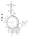
- FIG. 2 shows an apparatus for manufacturing a surface fastener with backing of filaments according to a second embodiment, in which the filament guide section of the first embodiment is modified.
- parts or elements substantially identical with those of the first embodiment are designated by like reference numerals.
- reference numeral 3 designates a filament pressure roller situated under the extrusion nozzle 1 so as to simultaneously press the molten resin and filaments F against part of the circumferential surface of the die wheel 2.
- the first filament guide 8a which guides the filaments F straightly in the direction of rotation of the die wheel 2, is situated under the filament pressure roller 3.
- the first filament guide 8a guides the filaments F in such a manner that the filament F goes around part of the circumferential surface of the filament pressure roller 3 and then supplies them to the gap between the pressure roller 3 and the die wheel 2.
- the second filament guide 8b is situated immediately upstream side of the resin pressing point between the die wheel 2 and the pressure roller 3, and likewise the first embodiment, supplies the filaments F while traversing by a predetermined width of traverse in the direction parallel to the axis of the die wheel 2.
- the upper arcuate surface 1a of the nozzle 1 has a curvature virtually equal to that of the die wheel 2, while the lower arcuate surface 1b has a predetermined gap for molding the substrate sheet 4a between itself and the circumferential surface of the die wheel 2.
- the extrusion nozzle 1 is the T-type die having the passageway 1c with the outlet 1d in the boundary of the upper and lower arcuate surfaces 1a, 1b, from which outlet 1d molten resin 4 is to be extruded in the form of a sheet.
- the molten resin extruded from the extrusion nozzle 1 is introduced into the gap defined between the extrusion nozzle 1 and the die wheel 2 and then fills the hook-forming cavities 5, which are provided in the circumferential surface of the die wheel 2, gradually along the rotation of the die wheel 2.
- the molten resin on the die wheel 2 is moved around virtually a quarter of the circumferential surface of the die wheel 2 and then is removed from the die wheel 2, while being gradually cooled by a non-illustrated cooling device inside the die wheel 2.
- the filaments F are guided simultaneously by the first and second filament guides 8a, 8b and are then fused integrally with the surface of the substrate sheet 4a, which are formed on the circumferential surface of the die wheel 2, as the filaments F are pressed against the surface of the substrate sheet 4a. At that time, if the filaments F are heated previously, there should be no difference in temperature between the filament F and the half-molten high-temperature substrate sheet 4a, thus causing reliable fusing.
- a multiplicity of hooks 4b are molded on the surface of the substrate sheet 4a, and the filaments F are arranged at desired distances longitudinally and transversely in the substrate sheet 4a as being fused with the substrate sheet 4a.
- this invention should by no means be limited to the foregoing embodiments, and it should not be necessary to arrange the filaments F in both the longitudinal and transverse directions, depending on the characteristic of the required surface fastener.
- a pair of traverse filaments F may be used as shown in FIG. 7, without arranging straight filaments F.
- only the straight filaments F may be arranged longitudinally of the substrate sheet 4a.
- a multiplicity of rows of hooks 4b are formed on the surface of the substrate sheet 4a and each of the hooks 4b has a pair of ribs 4c one on each of opposite side surfaces.
- the hooks 4b are directed in a common direction, and in the adjacent hook rows, they are directed in mutually opposite directions.
- the ribs 4c are effective in preventing the hooks 4b from falling flat.
- the adjacent hooks 4b may be directed in mutually opposite directions so that a surface fastener having no direction in coupling can be obtained.
- various kinds of molded surface fasteners in which filaments are arranged in the substrate sheet in various patterns can be continuously manufactured simply in a single process without requiring meticulous processes.
- the direction of engagement of the resulting surface fastener can be selectively secured among only longitudinal, only transverse and both, depending on the arrangement of the filaments.
- This surface fastener is excellent in dimensional precision as is free from being extended when it is cut into pieces in a subsequent step. Also in the sewing step, the surface fastener is free from any crack in the substrate sheet due to the sewing needle. Accordingly a durable and high-quality surface fastener can be obtained.
- the molten resin is extruded toward the die wheel in a direction right-angled to the peripheral surface of the die wheel.
- the molten resin may be extruded between an upper die wheel and a lower press wheel both of which co-rotate in opposite directions.
Abstract
Description
- This invention relates to a method for continuously molding a surface fastener, which has a multiplicity of engaging members on a surface of a plate-like substrate sheet, by extruding thermoplastic resin.
- The technology of extruding a substrate sheet using thermoplastic resin and, at the same time, molding hooks on one surface of the substrate sheet is already known by, for example, International Patent Application No. WO87/06522 . The molding method disclosed in this publication comprises extruding molten thermoplastic resin onto a circumferential surface of a drum-shape die wheel, in which a multiplicity of mold discs and a multiplicity of spacer plates are laminated alternately, filling the hook-forming cavities of the mold discs with the resin while pressing the resin on the drum surface to form a substrate sheet, and pulling molded hooks out of the cavities along with the substrate sheet in timed relation to the rotation of the drum while the resin is cooled. The mold disc has in one side surface hook-shape cavities extending radially from the circumferential surface toward the center and spaced circumferentially at predetermined distances. The side surfaces of the spacer plate are flat. The reason why the spacer plate is needed is that the cavities of the whole shape of the hook cannot be formed in a single mold.
- According to the surface fastener manufacturing method disclosed in the above-mentioned publication, since the surface fastener is merely molded continuously of thermoplastic resin, it would be extended due to a tension exerted on the surface fastener when it is cut into pieces, thus causing dimensional errors in the products. Further, when the resulting surface fastener is attached to a garment by sewing, the surface fastener would have cracks due to the sewing needle so that it cannot be sewn to the garment.
- With the foregoing problems in view, it is an object of this invention to provide a molding method for manufacturing a surface fastener effectively and simply which is free of extension though molded of thermoplastic resin by extrusion, is free from any crack during sewing and is stable in shape.
- As the result of various studies made in order to accomplish the above object, the present inventors have considered to attach a cloth, which is woven of warp and weft yarns, to the back surface of the substrate sheet, or to embed the cloth in the substrate sheet, while the substrate sheet and hooks are molded integrally. In this case, however, assuming that the characteristic of the surface fastener may be changed according to the yarn density, it would be necessary to prepare various kinds of cloth having differenet densities. Additionally, since it is sometimes required to prevent the surface fastener only from being extended or only from being cracked, it is not always necessary to give to the surface fastener toughness in both warp and weft directions. Consequently it has turned out that using the cloth is disadvantageous from an economical view point and in that it might impair the characteristic of the surface fastener.
- In other words, if the fiber filaments are used, it is possible to realize the optimum filament density simply by adjusting the number of filaments to be supplied and the speed of traverse, and it is possible to arrange the filaments either longitudinally or transversely easily. Accordingly it has turned out that using the fiber filaments is most advantageous. In order to mold the substrate sheet and the hooks integrally and to fuse the filaments of fiber material firmly with the substrate sheet, it is preferable to heat the filaments before joining to the substrate sheet. If the substrate sheet is adequately melted, it is not always necessary to preheat the filaments.
- According to a first aspect of the invention, the foregoing problems can be solved by a method for continuously manufacturing a surface fastener, comprising the steps of continuously extruding molten resin from an extrusion nozzle by a predetermined width toward a peripheral surface of a die wheel having a plurality of engaging-member-forming cavities for molding a plate-like substrate sheet of a predetermined width, while filling said cavities with a part of said molten resin, continuously introducing a plurality of fiber filaments straightly and parallel onto said extruded molten resin and/or traversing one or more of said fiber filaments by a predetermined width, integrating said fiber filaments with said plate-like substrate sheet as said die wheel is driven to rotate in the direction of extrusion of said molten resin, and successively forming a plurality of engaging members integrally on a surface of said substrate sheet, and positively taking up said molded surface fastener after cooling by a suitable cooling means.
- According to a second aspect of the invention, there is provided a method for continuously manufacturing a surface fastener, which comprises the steps of continuously extruding molten resin from an extrusion nozzle by a predetermined width, continuously introducing a plurality of fiber filaments straightly and parallel in a direction along rotation of a die wheel to an outlet of the extruded molten resin and/or traversing one or more of the fiber filaments by a predetermined width, introducing the molten resin extruded from the extrusion nozzle and the filaments into a predetermined gap for molding a plate-like substrate sheet between the nozzle and the die wheel, which has a multiplicity of hook-forming cavities in its circumferential surface and is rotatable in one direction, and at the same time, filling the engaging-member-forming cavities with a part of the molten resin, embedding the filaments in the substrate sheet of the extruded molten resin as the die wheel is driven to rotate in the direction of extrusion of the molten resin, successively forming a plurality of hooks integrally on a surface of the substrate sheet, and positively taking up the substrate sheet with the hooks molded thereon, after cooling by a suitable cooling means.
- According to a third aspect of the invention, there is also provided a method for continuously manufacturing a surface fastener, which comprises the steps of continuously extruding molten resin from an extrusion nozzle by a predetermined width, introducing the molten resin into a predetermined gap for molding a plate-like substrate sheet between the nozzle and a die wheel, which has a multiplicity of hook-forming cavities in its circumferential surface and is rotatable in one direction, and at the same time, filling the engaging-member-forming cavities with a part of the molten resin, continuously introducing a plurality of parallel fiber filaments straightly onto a plate-like substrate sheet of the extruded molten resin, which sheet revolves along the rotation of the die wheel, and/or traversing one or more of the fiber filaments by a predetermined width, to thereby fixedly attaching the fiber filaments to a surface of the substrate sheet, and positively taking up the substrate sheet with the hooks molded thereon, after cooling by a suitable cooling means.
- More specifically, in manufacturing the surface fastener according to the first method, molten resin extruded from the extrusion nozzle is forced into a gap between the extrusion nozzle and the die wheel, and the hook-forming cavities are progressively filled with a part of the molten resin to mold the hooks and to continuously mold a plate-like substrate sheet having a predetermined thickness and a predetermined width. The molten resin in contact with the die wheel is guided around part of the circumferential surface of the die wheel by the guide roller, during which the molten resin is cooled from the inside of the die wheel to gradually become hard. During this hardening, as the substrate sheet is pulled by a suitable force in the direction of extrusion, the individual hooks are removed smoothly from the cavity as it elastically deforms into a straight form. Immediately after that, the individual hook restores its original shape and the resulting hook is gradually cooled to become hard.
- Each of the filaments introduced to the vicinity to the outlet of the extrusion nozzle advances along the circumferential surface of the die wheel in the direction of rotation of the die wheel along the rotation of the die wheel while they are embedded in the molten resin. As a result, the filaments are embedded in and fused with the substrate sheet. The substrate sheet with the filaments and hooks integrally formed therewith are cooled into a half-hardened state from the inside of the die wheel and then are positively taken up. At a position immediately downstream of the die wheel, the surface fastener will be discharged as the surface of the substrate sheet is pressed by the guide roller.
- In the resulting surface fastener, since a plurality of parallel straight filaments arranged longitudinally of the substrate sheet cross in the substrate sheet one or more filaments meandering as traversed, the surface fastener will not be extended under tension during cutting and will not be cracked during sewing.
-
- FIG. 1 is a fragmentary vertical cross-sectional view showing a molding ap paratus for manufacturing a molded surface fastener, with backing of filaments, for carrying out a first embodiment of this invention;
- FIG. 2 is a fragmentary vertical cross-sectional view showing another molding apparatus for carrying out a second embodiment of the invention;
- FIG. 3 is a fragmentary plan view showing an example of surface fastener manufactured according to the first embodiment;
- FIG. 4 is a cross-sectional view taken along line A-A of FIG. 3;
- FIG. 5 is a plan view showing an example of arrangement of filaments according to this invention;
- FIG. 6 is a plan view showing another example of arrangement of filaments; and
- FIG. 7 is a plan view showing still another example of arrangement of filaments.
- Embodiments of this invention will now be described in detail with reference to the accompanying drawings.
- FIG. 1 is a fragmentary vertical cross-sectional view showing a surface fastener, in which fiber filaments are fixed to the back surface of a substrate sheet longitudinally and transversely and engaging members are molded on the front surface of the substrate sheet, as manufactured on an apparatus according to a first embodiment of this invention. In the first embodiment and a second embodiment described later, the engaging members are hooks. However, the shape of the engaging members should by no means be limited to hooks but they may have different shape such as anchor etc.
- In FIG. 1, reference numeral 1 designates an extrusion nozzle; the upper half of an end surface of the nozzle 1 is an
arcuate surface 1a having a curvature virtually equal to that of a die wheel 2 described below, while the lower half end surface is anarcuate surface 1b having a predetermined gap between thearcuate surface 1b and a curved surface of the die wheel 2 for molding a plate-like substrate sheet 4a. The extrusion nozzle 1 is a T-type die, from anoutlet 1d of whichmolten resin 4 is to be extruded in the form of a sheet. According to this embodiment, the extrusion nozzle 1 has a centrally extendingpassageway 1c. - The die wheel 2 is positioned in such a manner that part of its circumferential surface is close to the upper
arcuate surface 1a and is spaced a predetermined gap from the lowerarcuate surface 1b, and that its axis is parallel to theoutlet 1d. The circumferential surface of the die wheel 2 has a multiplicity of hook-formingcavities 5. Since the structure of the die wheel 2 is substantially identical with the structure disclosed in International Patent Application No. WO87/06522 , it is described here briefly. The die wheel 2 is in the form of a hollow drum having in it awater cooling jacket 2a. Centrally in the hollow drum, a multiplicity of ring-shape plates are laminated along the axis of the hollow drum. Each of every other ring-shape plates has in the front and back surfaces a multiplicity of hook-formingcavities 5 with the base of each hook opening to the circumferential surface of the drum. Both the front and back surfaces of each of non-illustrated ring-shape plates adjacent to the ring-shape plate having the hook-formingcavities 5 are flat. The die wheel 2 is rotatable, in a direction indicated by an arrow, as driven by a non-illustrated known drive unit. - A plurality of fiber filaments F are introduced into the gap between the upper
arcuate surface 1a and the circumferential surface of the die wheel 2 via a plurality ofparallel filament guides 8 arranged transversely of the extrusion nozzle 1. As shown in FIG. 1, afirst filament guide 8a indicated by solid lines is fixed to, for example, a non-illustrated frame and guides the filaments F straightly so as to feed them in the direction of rotation of the die wheel 2. Asecond filament guide 8b indicated by phantom lines in FIG. 1 is reciprocatingly moved by a predetermined width of traverse in a direction parallel to the axis of the die wheel 2 by a traverse device which is widely used in the field of textile machines. Accordingly the filaments F guided by thesecond filament guide 8b will be introduced into the gap between the upperarcuate surface 1a and the circumferential surface of the die wheel 2, meandering over a predetermined width of traverse. Likewise thefirst filament guides 8a, a plurality ofsecond filament guides 8b are arranged parallel to one another and have each a desired width of traverse so that various composite meandering patterns can be obtained, by synchronous traverse, as shown in FIGS. 5 through 7. Further, by varying the traverse speed, it is possible to vary as desired the distance of the filaments arranged in the direction of rotation of the die wheel 2. - Further, in, front (on the right side in FIG. 1) of the die wheel 2, a
guide roller 9 is situated, and in front of theguide roller 9, a set of upper andlower discharge rollers - The resin material and the fiber filament material to be used in this invention are exemplified by thermoplastic resin such as nylon, polyester and polypropylene. The resin material and the filament material may be identical with or different from each other. During the molding, the molten resin temperature, extrusion pressure, die wheel temperature, speed of rotation of the die wheel, etc. should of course be controlled in accordance with the material used.
- According to the apparatus constructed as mentioned above,
molten resin 4 extruded from the extrusion nozzle 1 is forced into the gap between the extrusion nozzle 1 and the die wheel 2 in rotation, and a part of the extrudedmolten resin 4 is gradually charged in the hook-formingcavities 5 tomold hooks 4b and to continuously mold the plate-like substrate sheet 4a having a predetermined thickness and a predetermined width. The molded substrate sheet and hooks 4a, 4b are moved around substantially a half of the circumferential surface of the die wheel 2 as guided by theguide roller 9, during which they are cooled from the inside of the die wheel 2 to gradually become hard. During this hardening, when the moldedsubstrate sheet 4a is pulled in the direction of extrusion by a suitable force, theindividual hooks 4b are removed smoothly from thecavities 5 as they elastically deform into a straight form. Immediately after that, thehooks 4b restore their original shape and hence are gradually cooled to become hard. - The individual filaments F introduced to the vicinity to the
outlet 1b of the extrusion nozzle 1 advance along the circumferential surface of the die wheel 2 in the direction of rotation of the die wheel 2 along the rotation of the die wheel 2 while they are embedded in the molten resin. As a result, the filaments F are embedded in and fused with thesubstrate sheet 4a as shown in FIGS. 3 and 4. Thesubstrate sheet 4a with the filaments F fused therewith and thehooks 4b are cooled into a half-hardened state from the inside of the die wheel 2 and then are positively taken up. At a position immediately downstream of the die wheel 2, the surface fastener is discharged as the surface of thesubstrate sheet 4a is pressed by theguide roller 9. - In this embodiment, in order to remove the resin molded product (surface fastener with backing of filaments) from the die wheel 2, a set of upper and
lower discharge rollers discharge rollers hooks 4b so that thehooks 4b are kept from being damaged. The rotating speed of thedischarge rollers hooks 4b can be removed smoothly from the hook-formingcavities 5. - In the resulting surface fastener, since a plurality of parallel straight filaments F arranged longitudinally of the
substrate sheet 4a cross in thesubstrate sheet 4a one or more filaments F meandering as traversed, the surface fastener will not be extended under tension during cutting and will not be cracked during sewing. - FIG. 2 shows an apparatus for manufacturing a surface fastener with backing of filaments according to a second embodiment, in which the filament guide section of the first embodiment is modified. In the second embodiment, parts or elements substantially identical with those of the first embodiment are designated by like reference numerals.
- In FIG. 2, reference numeral 3 designates a filament pressure roller situated under the extrusion nozzle 1 so as to simultaneously press the molten resin and filaments F against part of the circumferential surface of the die wheel 2. The
first filament guide 8a, which guides the filaments F straightly in the direction of rotation of the die wheel 2, is situated under the filament pressure roller 3. Thefirst filament guide 8a guides the filaments F in such a manner that the filament F goes around part of the circumferential surface of the filament pressure roller 3 and then supplies them to the gap between the pressure roller 3 and the die wheel 2. Thesecond filament guide 8b is situated immediately upstream side of the resin pressing point between the die wheel 2 and the pressure roller 3, and likewise the first embodiment, supplies the filaments F while traversing by a predetermined width of traverse in the direction parallel to the axis of the die wheel 2. - Therefore, in the second embodiment, the upper
arcuate surface 1a of the nozzle 1 has a curvature virtually equal to that of the die wheel 2, while the lowerarcuate surface 1b has a predetermined gap for molding thesubstrate sheet 4a between itself and the circumferential surface of the die wheel 2. The extrusion nozzle 1 is the T-type die having thepassageway 1c with theoutlet 1d in the boundary of the upper and lowerarcuate surfaces outlet 1dmolten resin 4 is to be extruded in the form of a sheet. - According to the second embodiment, the molten resin extruded from the extrusion nozzle 1 is introduced into the gap defined between the extrusion nozzle 1 and the die wheel 2 and then fills the hook-forming
cavities 5, which are provided in the circumferential surface of the die wheel 2, gradually along the rotation of the die wheel 2. The molten resin on the die wheel 2 is moved around virtually a quarter of the circumferential surface of the die wheel 2 and then is removed from the die wheel 2, while being gradually cooled by a non-illustrated cooling device inside the die wheel 2. - During this molding, the filaments F are guided simultaneously by the first and second filament guides 8a, 8b and are then fused integrally with the surface of the
substrate sheet 4a, which are formed on the circumferential surface of the die wheel 2, as the filaments F are pressed against the surface of thesubstrate sheet 4a. At that time, if the filaments F are heated previously, there should be no difference in temperature between the filament F and the half-molten high-temperature substrate sheet 4a, thus causing reliable fusing. - As mentioned above, in the surface fastener manufactured according to each of the foregoing embodiments, a multiplicity of
hooks 4b are molded on the surface of thesubstrate sheet 4a, and the filaments F are arranged at desired distances longitudinally and transversely in thesubstrate sheet 4a as being fused with thesubstrate sheet 4a. However, this invention should by no means be limited to the foregoing embodiments, and it should not be necessary to arrange the filaments F in both the longitudinal and transverse directions, depending on the characteristic of the required surface fastener. A pair of traverse filaments F may be used as shown in FIG. 7, without arranging straight filaments F. Alternatively, only the straight filaments F may be arranged longitudinally of thesubstrate sheet 4a. - In the foregoing embodiments, as is apparent from FIGS. 3 and 4, a multiplicity of rows of
hooks 4b are formed on the surface of thesubstrate sheet 4a and each of thehooks 4b has a pair ofribs 4c one on each of opposite side surfaces. In the same hook row, thehooks 4b are directed in a common direction, and in the adjacent hook rows, they are directed in mutually opposite directions. Although they may be omitted, theribs 4c are effective in preventing thehooks 4b from falling flat. In this invention, in the same hook row, theadjacent hooks 4b may be directed in mutually opposite directions so that a surface fastener having no direction in coupling can be obtained. Various modifications may be suggested within the scope and concept of this invention. - As is explained above in detail, according to the molding method of this invention, various kinds of molded surface fasteners, in which filaments are arranged in the substrate sheet in various patterns can be continuously manufactured simply in a single process without requiring meticulous processes. The direction of engagement of the resulting surface fastener can be selectively secured among only longitudinal, only transverse and both, depending on the arrangement of the filaments. This surface fastener is excellent in dimensional precision as is free from being extended when it is cut into pieces in a subsequent step. Also in the sewing step, the surface fastener is free from any crack in the substrate sheet due to the sewing needle. Accordingly a durable and high-quality surface fastener can be obtained.
- In the above-described embodiments, the molten resin is extruded toward the die wheel in a direction right-angled to the peripheral surface of the die wheel. Alternatively, the molten resin may be extruded between an upper die wheel and a lower press wheel both of which co-rotate in opposite directions.
Claims (3)
- A method for continuously manufacturing a surface fastener, comprising:(a) continuously extruding molten resin (4) from an extrusion nozzle (1) by a predetermined width toward a peripheral surface of a die wheel (2) having a plurality of engaging-member-forming cavities (5) for molding a plate-like substrate sheet (4a) of a predetermined width, while filling said cavities (5) with a part of said molten resin (4);(b) continuously introducing a plurality of fiber filaments (F) straightly and parallel onto said extruded molten resin (4) and/or traversing one or more of said fiber filaments (F) by a predetermined width;(c) integrating said fiber filaments (F) with said plate-like substrate sheet (4a) as said die wheel (2) is driven to rotate in the direction of extrusion of said molten resin (4), and successively forming a plurality of engaging members (4b) integrally on a surface of said substrate sheet (4a); and(d) positively taking up said molded surface fastener after cooling by a suitable means (2a).
- A method for continuously manufacturing a surface fastener, comprising:(a) continuously extruding molten resin (4) from an extrusion nozzle (1) by a predetermined width;(b) continuously introducing a plurality of fiber filaments (F) straightly and parallel in a direction along rotation of a die wheel (2) to an outlet of said extruded molten resin (4), and/or traversing one or more of said fiber filaments (F) by a predetermined width;(c) introducing said molten resin (4) extruded from said extrusion nozzle (1) and said filaments (F) into a predetermined gap for molding a plate-like substrate sheet (4a) between said nozzle (1) and said die wheel (2), which has a multiplicity of engaing-member-forming cavities (5) in its circumferential surface and is rotatable in one direction, and at the same time, filling said engaging-member-forming cavities (5) with a part of said molten resin (4);(d) embedding said filaments (F) in said plate-like substrate sheet (4a) of said extruded molten resin (4) as said die wheel (2) is driven to rotate in the direction of extrusion of said molten resin (4), and successively forming a plurality of engaging members (4b) integrally on a surface of said substrate sheet (4a); and(e) positively taking up said substrate sheet (4a) with said engaging members (4b) molded thereon, after cooling by a suitable cooling means (2a).
- A method for continuously manufacturing a surface fastener, comprising:(a) continuously extruding molten resin (4) from an extrusion nozzle (1) by a predetermined width;(b) introducing said molten resin (4) into a predetermined gap for molding a plate-like substrate sheet (4a) between said nozzle (1) and a die wheel (2), which has a multiplicity of engaging-member-forming cavities (5) in its circumferential surface and is rotatable in one direction, and at the same time, filling said engaging-member-forming cavities (5) with a part of said molten resin (4);(c) continuously introducing a plurality of parallel fiber filaments (F) straightly onto said plate-like substrate sheet (4a) of said extruded molten resin (4), which sheet (4a) revolves along the rotation of said die wheel (2), and/or traversing one or more of said fiber filaments (F) by a predetermined width, to thereby fixedly attaching said fiber filaments (F) to a surface of said substrate sheet (4a); and(d) positively taking up said substrate sheet (4a) with said engaging members (4b) molded thereon, after cooling by a suitable cooling means (2a).
Applications Claiming Priority (3)
| Application Number | Priority Date | Filing Date | Title |
|---|---|---|---|
| JP337498/93 | 1993-12-28 | ||
| JP33749893 | 1993-12-28 | ||
| JP5337498A JP2731106B2 (en) | 1993-12-28 | 1993-12-28 | Manufacturing method of hook-and-loop fastener |
Publications (3)
| Publication Number | Publication Date |
|---|---|
| EP0661008A2 true EP0661008A2 (en) | 1995-07-05 |
| EP0661008A3 EP0661008A3 (en) | 1996-08-28 |
| EP0661008B1 EP0661008B1 (en) | 2002-07-17 |
Family
ID=18309222
Family Applications (1)
| Application Number | Title | Priority Date | Filing Date |
|---|---|---|---|
| EP94119496A Expired - Lifetime EP0661008B1 (en) | 1993-12-28 | 1994-12-09 | Surface fastener manufacturing method |
Country Status (8)
| Country | Link |
|---|---|
| US (1) | US6143222A (en) |
| EP (1) | EP0661008B1 (en) |
| JP (1) | JP2731106B2 (en) |
| CN (1) | CN1048937C (en) |
| BR (1) | BR9405469A (en) |
| DE (1) | DE69430984T2 (en) |
| ES (1) | ES2177562T3 (en) |
| TW (1) | TW272960B (en) |
Cited By (10)
| Publication number | Priority date | Publication date | Assignee | Title |
|---|---|---|---|---|
| EP0740910A2 (en) * | 1995-05-02 | 1996-11-06 | Ykk Corporation | Molded surface fastener and method for manufacturing the same |
| EP0745337A1 (en) * | 1995-06-02 | 1996-12-04 | Ykk Corporation | Molded surface fastener and method for manufacturing the same |
| EP0749707A1 (en) * | 1995-06-20 | 1996-12-27 | Ykk Corporation | Molded surface fastener and method for manufacturing the same |
| EP0830930A1 (en) * | 1996-09-19 | 1998-03-25 | Ykk Corporation | Molded surface fastener member and method of manufacturing the member |
| WO1998023181A1 (en) * | 1996-11-26 | 1998-06-04 | Velcro Industries, B.V. | Fastening member with loops and process and machine for producing it |
| EP0895731A2 (en) * | 1997-08-05 | 1999-02-10 | Ykk Corporation | Female engaging member of surface fastener and method of manufacturing the same |
| EP0925770A3 (en) * | 1997-12-24 | 2000-03-15 | Ykk Corporation | Fastening device of disposable diaper |
| US6248419B1 (en) | 1991-08-16 | 2001-06-19 | Velcro Industries B.V. | Laminated hook fastener |
| EP1190636A2 (en) * | 1995-03-07 | 2002-03-27 | Velcro Industries B.V. | Enhanced flexibility fastener, method and apparatus for its making, and product incorporating it |
| WO2003059111A1 (en) * | 2002-01-15 | 2003-07-24 | Velcro Industries B.V. | Interface tape |
Families Citing this family (11)
| Publication number | Priority date | Publication date | Assignee | Title |
|---|---|---|---|---|
| US20030070391A1 (en) * | 2000-04-26 | 2003-04-17 | Tachauer Ernesto S. | Fastening with wide fastening membrane |
| DE10039937A1 (en) * | 2000-08-16 | 2002-03-07 | Binder Gottlieb Gmbh & Co | Method of making an adhesive fastener part |
| US6484371B1 (en) * | 2001-02-27 | 2002-11-26 | 3M Innovative Properties Company | High strength, flexible, light weight hook and loop bundling straps |
| US6692674B1 (en) * | 2002-11-27 | 2004-02-17 | Velcro Industries B.V. | Discrete fastener regions |
| US7919034B2 (en) * | 2003-01-30 | 2011-04-05 | Tac-Fast Georgia L.L.C. | System and methods of manufacturing hook plates |
| US7373699B2 (en) * | 2003-10-15 | 2008-05-20 | Velcro Industries B.V. | Plastic sheet reinforcement |
| US7108814B2 (en) * | 2004-11-24 | 2006-09-19 | Velcro Industries B.V. | Molded touch fasteners and methods of manufacture |
| US7422783B2 (en) * | 2004-11-24 | 2008-09-09 | Velcro Industries B.V. | Submerged hooks |
| DE102008056052A1 (en) * | 2008-11-05 | 2009-09-17 | SaarGummi technologies S.à.r.l. | Continuous strand i.e. sealing strand, manufacturing method, involves continuously opening mold cavity at distance to casting position by guiding molding units away from each other to demold hard continuous strand in mold cavity |
| CN102940345B (en) * | 2012-11-28 | 2015-10-28 | 陈胜华 | The manufacture method of plastic hook fastener and equipment and plastic hook fastener |
| DE102015209394A1 (en) * | 2015-05-22 | 2016-11-24 | Leoni Kabel Holding Gmbh | Method and device for producing stranded and extruded material |
Citations (5)
| Publication number | Priority date | Publication date | Assignee | Title |
|---|---|---|---|---|
| US4097634A (en) * | 1976-04-19 | 1978-06-27 | Minnesota Mining And Manufacturing Company | Thermoplastic resin molding of complex decorative relief |
| JPS5656844A (en) * | 1979-10-17 | 1981-05-19 | Kasai Kogyo Co Ltd | Extrusion molding of plastic form |
| WO1987006522A1 (en) * | 1986-04-25 | 1987-11-05 | Actief N.V. | Separable fastener member and method and apparatus for producing same |
| JPH01150528A (en) * | 1987-12-07 | 1989-06-13 | Kuraray Co Ltd | Thermoplastic resin sheet-like object excellent in antistatic property |
| EP0580073A2 (en) * | 1992-07-22 | 1994-01-26 | Ykk Corporation | Method and apparatus for manufacturing a material-backed engaging member for surface fastener |
Family Cites Families (16)
| Publication number | Priority date | Publication date | Assignee | Title |
|---|---|---|---|---|
| US3168605A (en) * | 1963-10-03 | 1965-02-02 | Bayer Ag | Process for the production of webs of elastic synthetic resins |
| US3594865A (en) * | 1969-07-10 | 1971-07-27 | American Velcro Inc | Apparatus for molding plastic shapes in molding recesses formed in moving endless wire dies |
| US3608035A (en) * | 1969-08-01 | 1971-09-21 | Opti Holding Ag | Method of making slide fasteners |
| US3758657A (en) * | 1971-12-01 | 1973-09-11 | American Velcro Inc | Production of a continuous molded plastic strip |
| JPS54161439A (en) * | 1978-06-09 | 1979-12-21 | Yoshida Kogyo Kk | Method and device for making element train for slide fastener |
| US4872243A (en) * | 1984-04-16 | 1989-10-10 | Velcro Industries B.V. | Multi-hook fastener member |
| US4769202A (en) * | 1985-11-29 | 1988-09-06 | The B. F. Goodrich Company | Process of making a conveyor belt |
| US4999067A (en) * | 1989-02-13 | 1991-03-12 | Erblok Associates | Method for making a hermaphrodite hook and loop fasteners |
| ATE151338T1 (en) * | 1991-06-21 | 1997-04-15 | Procter & Gamble | SCREEN PRINTING METHOD FOR PRODUCING A SURFACE ZIPPER AND SURFACE ZIPPER PRODUCED IN THIS WAY |
| US5260015A (en) * | 1991-08-16 | 1993-11-09 | Velcro Industries, B.V. | Method for making a laminated hook fastener |
| JP2756211B2 (en) * | 1992-06-17 | 1998-05-25 | ワイケイケイ株式会社 | Method and apparatus for manufacturing integrally molded surface fastener having engagement pieces on both sides |
| US5620769A (en) * | 1995-05-02 | 1997-04-15 | Ykk Corporation | Molded surface fastener and method for manufacturing the same |
| JPH08299032A (en) * | 1995-05-09 | 1996-11-19 | Ykk Kk | Molded hook-and-loop fastener |
| JPH08322609A (en) * | 1995-06-02 | 1996-12-10 | Ykk Kk | Molded hook and loop fastener, and its manufacture |
| JP3425501B2 (en) * | 1995-12-22 | 2003-07-14 | ワイケイケイ株式会社 | Hook-and-loop fastener |
| JPH1150528A (en) * | 1997-08-05 | 1999-02-23 | Okabe Co Ltd | Method for joining reinforced concrete column with beam |
-
1993
- 1993-12-28 JP JP5337498A patent/JP2731106B2/en not_active Expired - Lifetime
-
1994
- 1994-12-09 ES ES94119496T patent/ES2177562T3/en not_active Expired - Lifetime
- 1994-12-09 TW TW083111477A patent/TW272960B/zh active
- 1994-12-09 DE DE69430984T patent/DE69430984T2/en not_active Expired - Fee Related
- 1994-12-09 EP EP94119496A patent/EP0661008B1/en not_active Expired - Lifetime
- 1994-12-27 CN CN94107614A patent/CN1048937C/en not_active Expired - Fee Related
- 1994-12-28 BR BR9405469A patent/BR9405469A/en not_active IP Right Cessation
-
1996
- 1996-08-21 US US08/701,252 patent/US6143222A/en not_active Expired - Fee Related
Patent Citations (5)
| Publication number | Priority date | Publication date | Assignee | Title |
|---|---|---|---|---|
| US4097634A (en) * | 1976-04-19 | 1978-06-27 | Minnesota Mining And Manufacturing Company | Thermoplastic resin molding of complex decorative relief |
| JPS5656844A (en) * | 1979-10-17 | 1981-05-19 | Kasai Kogyo Co Ltd | Extrusion molding of plastic form |
| WO1987006522A1 (en) * | 1986-04-25 | 1987-11-05 | Actief N.V. | Separable fastener member and method and apparatus for producing same |
| JPH01150528A (en) * | 1987-12-07 | 1989-06-13 | Kuraray Co Ltd | Thermoplastic resin sheet-like object excellent in antistatic property |
| EP0580073A2 (en) * | 1992-07-22 | 1994-01-26 | Ykk Corporation | Method and apparatus for manufacturing a material-backed engaging member for surface fastener |
Non-Patent Citations (2)
| Title |
|---|
| PATENT ABSTRACTS OF JAPAN vol. 13, no. 411 (M-869), 11 September 1989 & JP-A-01 150528 (KURARAY CO LTD), 13 June 1989, * |
| PATENT ABSTRACTS OF JAPAN vol. 5, no. 116 (M-080), 25 July 1981 & JP-A-56 056844 (KASAI KOGYO CO LTD), 19 May 1981, * |
Cited By (21)
| Publication number | Priority date | Publication date | Assignee | Title |
|---|---|---|---|---|
| US6248419B1 (en) | 1991-08-16 | 2001-06-19 | Velcro Industries B.V. | Laminated hook fastener |
| EP1190636A3 (en) * | 1995-03-07 | 2003-11-05 | Velcro Industries B.V. | Enhanced flexibility fastener, method and apparatus for its making, and product incorporating it |
| EP1190636A2 (en) * | 1995-03-07 | 2002-03-27 | Velcro Industries B.V. | Enhanced flexibility fastener, method and apparatus for its making, and product incorporating it |
| EP0740910A2 (en) * | 1995-05-02 | 1996-11-06 | Ykk Corporation | Molded surface fastener and method for manufacturing the same |
| EP0740910A3 (en) * | 1995-05-02 | 1997-04-16 | Ykk Corp | Molded surface fastener and method for manufacturing the same |
| US5938997A (en) * | 1995-06-02 | 1999-08-17 | Ykk Corporation | Molded surface fastener and method for manufacturing the same |
| US5702797A (en) * | 1995-06-02 | 1997-12-30 | Ykk Corporation | Molded surface fastener and method for manufacturing the same |
| US5948337A (en) * | 1995-06-02 | 1999-09-07 | Ykk Corporation | Molded surface fastener and method for manufacturing the same |
| EP0745337A1 (en) * | 1995-06-02 | 1996-12-04 | Ykk Corporation | Molded surface fastener and method for manufacturing the same |
| US5643651A (en) * | 1995-06-20 | 1997-07-01 | Ykk Corporation | Molded surface fastener and method for manufacturing the same |
| US5851467A (en) * | 1995-06-20 | 1998-12-22 | Ykk Corporation | Molded surface fastener and method for manufacturing the same |
| EP0749707A1 (en) * | 1995-06-20 | 1996-12-27 | Ykk Corporation | Molded surface fastener and method for manufacturing the same |
| EP0830930A1 (en) * | 1996-09-19 | 1998-03-25 | Ykk Corporation | Molded surface fastener member and method of manufacturing the member |
| US6060146A (en) * | 1996-09-19 | 2000-05-09 | Ykk Corporation | Molded surface fastener member and method of manufacturing the member |
| WO1998023181A1 (en) * | 1996-11-26 | 1998-06-04 | Velcro Industries, B.V. | Fastening member with loops and process and machine for producing it |
| US5981027A (en) * | 1996-11-26 | 1999-11-09 | Velcro Industries B.V. | Fastening member with loops and process and machine for producing it |
| EP0895731A2 (en) * | 1997-08-05 | 1999-02-10 | Ykk Corporation | Female engaging member of surface fastener and method of manufacturing the same |
| EP0895731A3 (en) * | 1997-08-05 | 1999-09-08 | Ykk Corporation | Female engaging member of surface fastener and method of manufacturing the same |
| EP0925770A3 (en) * | 1997-12-24 | 2000-03-15 | Ykk Corporation | Fastening device of disposable diaper |
| WO2003059111A1 (en) * | 2002-01-15 | 2003-07-24 | Velcro Industries B.V. | Interface tape |
| US6913810B2 (en) | 2002-01-15 | 2005-07-05 | Velcro Industries B.V. | Interface tape |
Also Published As
| Publication number | Publication date |
|---|---|
| DE69430984D1 (en) | 2002-08-22 |
| EP0661008B1 (en) | 2002-07-17 |
| ES2177562T3 (en) | 2002-12-16 |
| US6143222A (en) | 2000-11-07 |
| EP0661008A3 (en) | 1996-08-28 |
| CN1108998A (en) | 1995-09-27 |
| JP2731106B2 (en) | 1998-03-25 |
| BR9405469A (en) | 1995-09-19 |
| TW272960B (en) | 1996-03-21 |
| CN1048937C (en) | 2000-02-02 |
| DE69430984T2 (en) | 2003-02-20 |
| JPH07184707A (en) | 1995-07-25 |
Similar Documents
| Publication | Publication Date | Title |
|---|---|---|
| US6143222A (en) | Surface fastener manufacturing method | |
| US5851467A (en) | Molded surface fastener and method for manufacturing the same | |
| KR0179238B1 (en) | Molded surface fastener | |
| EP0740910B1 (en) | Molded surface fastener and method for manufacturing the same | |
| EP0830930B1 (en) | Molded surface fastener member and method of manufacturing the member | |
| US5393475A (en) | Method and apparatus for continuously producing an integrally molded double-sided surface fastener | |
| US5537723A (en) | Molded surface fastener | |
| US5512234A (en) | Method and apparatus for manufacturing surface fastener | |
| US6604264B1 (en) | Female engaging member of surface fastener and production apparatus thereof | |
| EP0745337B1 (en) | Molded surface fastener and method for manufacturing the same | |
| KR100288952B1 (en) | Female fastening member of the surface fastener and its manufacturing method | |
| EP0942667B1 (en) | Fastening member with loops and process and machine for producing it | |
| JPH09308509A (en) | Formed plane fastener having backing member on backside and manufacture |
Legal Events
| Date | Code | Title | Description |
|---|---|---|---|
| PUAI | Public reference made under article 153(3) epc to a published international application that has entered the european phase |
Free format text: ORIGINAL CODE: 0009012 |
|
| AK | Designated contracting states |
Kind code of ref document: A2 Designated state(s): BE DE ES FR GB IT |
|
| PUAL | Search report despatched |
Free format text: ORIGINAL CODE: 0009013 |
|
| AK | Designated contracting states |
Kind code of ref document: A3 Designated state(s): BE DE ES FR GB IT |
|
| 17P | Request for examination filed |
Effective date: 19961128 |
|
| 17Q | First examination report despatched |
Effective date: 19990210 |
|
| GRAG | Despatch of communication of intention to grant |
Free format text: ORIGINAL CODE: EPIDOS AGRA |
|
| GRAG | Despatch of communication of intention to grant |
Free format text: ORIGINAL CODE: EPIDOS AGRA |
|
| GRAG | Despatch of communication of intention to grant |
Free format text: ORIGINAL CODE: EPIDOS AGRA |
|
| GRAH | Despatch of communication of intention to grant a patent |
Free format text: ORIGINAL CODE: EPIDOS IGRA |
|
| GRAH | Despatch of communication of intention to grant a patent |
Free format text: ORIGINAL CODE: EPIDOS IGRA |
|
| GRAA | (expected) grant |
Free format text: ORIGINAL CODE: 0009210 |
|
| AK | Designated contracting states |
Kind code of ref document: B1 Designated state(s): BE DE ES FR GB IT |
|
| REG | Reference to a national code |
Ref country code: GB Ref legal event code: FG4D |
|
| PGFP | Annual fee paid to national office [announced via postgrant information from national office to epo] |
Ref country code: BE Payment date: 20020718 Year of fee payment: 9 |
|
| REF | Corresponds to: |
Ref document number: 69430984 Country of ref document: DE Date of ref document: 20020822 |
|
| PGFP | Annual fee paid to national office [announced via postgrant information from national office to epo] |
Ref country code: GB Payment date: 20021204 Year of fee payment: 9 |
|
| PGFP | Annual fee paid to national office [announced via postgrant information from national office to epo] |
Ref country code: FR Payment date: 20021210 Year of fee payment: 9 |
|
| PGFP | Annual fee paid to national office [announced via postgrant information from national office to epo] |
Ref country code: DE Payment date: 20021212 Year of fee payment: 9 |
|
| REG | Reference to a national code |
Ref country code: ES Ref legal event code: FG2A Ref document number: 2177562 Country of ref document: ES Kind code of ref document: T3 |
|
| ET | Fr: translation filed | ||
| PGFP | Annual fee paid to national office [announced via postgrant information from national office to epo] |
Ref country code: ES Payment date: 20030121 Year of fee payment: 9 |
|
| PLBE | No opposition filed within time limit |
Free format text: ORIGINAL CODE: 0009261 |
|
| STAA | Information on the status of an ep patent application or granted ep patent |
Free format text: STATUS: NO OPPOSITION FILED WITHIN TIME LIMIT |
|
| 26N | No opposition filed |
Effective date: 20030422 |
|
| PG25 | Lapsed in a contracting state [announced via postgrant information from national office to epo] |
Ref country code: GB Free format text: LAPSE BECAUSE OF NON-PAYMENT OF DUE FEES Effective date: 20031209 |
|
| PG25 | Lapsed in a contracting state [announced via postgrant information from national office to epo] |
Ref country code: ES Free format text: LAPSE BECAUSE OF NON-PAYMENT OF DUE FEES Effective date: 20031210 |
|
| PG25 | Lapsed in a contracting state [announced via postgrant information from national office to epo] |
Ref country code: BE Free format text: LAPSE BECAUSE OF NON-PAYMENT OF DUE FEES Effective date: 20031231 |
|
| BERE | Be: lapsed |
Owner name: *YKK CORP. Effective date: 20031231 |
|
| PG25 | Lapsed in a contracting state [announced via postgrant information from national office to epo] |
Ref country code: DE Free format text: LAPSE BECAUSE OF NON-PAYMENT OF DUE FEES Effective date: 20040701 |
|
| GBPC | Gb: european patent ceased through non-payment of renewal fee |
Effective date: 20031209 |
|
| PG25 | Lapsed in a contracting state [announced via postgrant information from national office to epo] |
Ref country code: FR Free format text: LAPSE BECAUSE OF NON-PAYMENT OF DUE FEES Effective date: 20040831 |
|
| REG | Reference to a national code |
Ref country code: FR Ref legal event code: ST |
|
| REG | Reference to a national code |
Ref country code: ES Ref legal event code: FD2A Effective date: 20031210 |
|
| PG25 | Lapsed in a contracting state [announced via postgrant information from national office to epo] |
Ref country code: IT Free format text: LAPSE BECAUSE OF NON-PAYMENT OF DUE FEES Effective date: 20051209 |