EP0671268A1 - Ink jet recording apparatus - Google Patents
Ink jet recording apparatus Download PDFInfo
- Publication number
- EP0671268A1 EP0671268A1 EP94921845A EP94921845A EP0671268A1 EP 0671268 A1 EP0671268 A1 EP 0671268A1 EP 94921845 A EP94921845 A EP 94921845A EP 94921845 A EP94921845 A EP 94921845A EP 0671268 A1 EP0671268 A1 EP 0671268A1
- Authority
- EP
- European Patent Office
- Prior art keywords
- recording medium
- ink jet
- ink
- dye
- recording apparatus
- Prior art date
- Legal status (The legal status is an assumption and is not a legal conclusion. Google has not performed a legal analysis and makes no representation as to the accuracy of the status listed.)
- Withdrawn
Links
Images


Classifications
-
- B—PERFORMING OPERATIONS; TRANSPORTING
- B41—PRINTING; LINING MACHINES; TYPEWRITERS; STAMPS
- B41J—TYPEWRITERS; SELECTIVE PRINTING MECHANISMS, i.e. MECHANISMS PRINTING OTHERWISE THAN FROM A FORME; CORRECTION OF TYPOGRAPHICAL ERRORS
- B41J11/00—Devices or arrangements of selective printing mechanisms, e.g. ink-jet printers or thermal printers, for supporting or handling copy material in sheet or web form
- B41J11/0015—Devices or arrangements of selective printing mechanisms, e.g. ink-jet printers or thermal printers, for supporting or handling copy material in sheet or web form for treating before, during or after printing or for uniform coating or laminating the copy material before or after printing
-
- B—PERFORMING OPERATIONS; TRANSPORTING
- B41—PRINTING; LINING MACHINES; TYPEWRITERS; STAMPS
- B41J—TYPEWRITERS; SELECTIVE PRINTING MECHANISMS, i.e. MECHANISMS PRINTING OTHERWISE THAN FROM A FORME; CORRECTION OF TYPOGRAPHICAL ERRORS
- B41J2/00—Typewriters or selective printing mechanisms characterised by the printing or marking process for which they are designed
- B41J2/005—Typewriters or selective printing mechanisms characterised by the printing or marking process for which they are designed characterised by bringing liquid or particles selectively into contact with a printing material
- B41J2/01—Ink jet
- B41J2/21—Ink jet for multi-colour printing
- B41J2/2107—Ink jet for multi-colour printing characterised by the ink properties
- B41J2/2114—Ejecting transparent or white coloured liquids, e.g. processing liquids
-
- B—PERFORMING OPERATIONS; TRANSPORTING
- B41—PRINTING; LINING MACHINES; TYPEWRITERS; STAMPS
- B41M—PRINTING, DUPLICATING, MARKING, OR COPYING PROCESSES; COLOUR PRINTING
- B41M7/00—After-treatment of prints, e.g. heating, irradiating, setting of the ink, protection of the printed stock
- B41M7/0027—After-treatment of prints, e.g. heating, irradiating, setting of the ink, protection of the printed stock using protective coatings or layers by lamination or by fusion of the coatings or layers
Definitions
- the present invention relates to an ink jet recording apparatus having a means for forming on a recording medium a dye acceptor layer which fixes and holds a dye by way of an intercalation.
- One of the methods of outputting images such as documents, graphic representations, or the like generated by personal computers or the like onto recording mediums such as sheets of paper, OHP films, or the like is known as an ink jet recording process.
- an ink in the form of a solution is ejected from a nozzle toward a recording medium by a drive source which employs an electric field, heat, pressure, or the like for thereby forming an image on the recording medium.
- the ink jet recording process is advantageous in that it produces a low level of noise, requires a low running cost, can form images on sheets of ordinary paper, and does not discharge a waste material such as ink ribbons. Therefore, ink jet recording apparatus have been finding widespread use in recent years as recording apparatus for office or personal use.
- the ink jet recording process is, however, disadvantageous in that images formed on recording mediums by this process have poor fixability properties, particularly water resistance and light resistance.
- an ink for use in ink jet recording is composed of a water-soluble dye.
- the ink is ejected toward a recording medium, and after the ink has been dried, its water-soluble dye remains on the recording medium and is held thereon by the van der Waals forces or hydrogen bonding for thereby fixing an image to the recording medium. Therefore, when a solvent such as water or the like which has a large affinity for the water-soluble dye is supplied to the recorded image, the dye is eluted, causing the image to blur.
- the dye also moves, causing the image to blur, when the water-soluble dye which forms the image on the recording medium is supplied with thermal or light energy that is large enough to cancel out the van der Waals forces or hydrogen bonding between the dye and the recording medium. Furthermore, upon exposure of the dye which forms the image to light such as ultraviolet radiation or the like, the molecules of the dye itself are destroyed, causing the image to be faded, discolored, or lowered in density. Therefore, images formed by the dye are also of low light resistance.
- the water resistance of images formed according to the ink jet recording process can be improved by using a recording medium of sized paper or a recording medium coated with a resin.
- the resin to be coated on the recording medium comprises a hydrophilic resin for allowing image to be formed by a water-soluble dye.
- Attempts have also been made to improve the light resistance of images formed according to the ink jet recording process by selecting a dye having a certain basic skeleton or introducing a certain substituent group into a side chain of dye molecules thereby to limit the molecular structure of the dye.
- the recording medium of sized paper is used to improve the water resistance of images formed according to the ink jet recording process, then it takes a long time to fix the ink to the recording medium as the recording medium has low ink absorption.
- the recording medium coated with a hydrophilic resin If used, then it has good ink absorption, but tends to form ink dots of large diameter or ink dots having blurred edges. Since the resin coated on the recording medium is hydrophilic, it essentially is not sufficiently effective to improve the water resistance of recorded images. Another problem of the recording medium coated with a hydrophilic resin is that it impairs the basic advantage of the ink jet recording process that sheets of ordinary paper can be used as the recording medium.
- the present invention has been made to solve the above problems of the prior art.
- a dye acceptor layer composed of an intercalation compound for holding a dye by way of an intercalation may be formed on a recording medium such as of plain paper, that a means for forming such a dye acceptor layer may be included in an ink jet recording apparatus, that the dye acceptor layer may be formed by expelling or spraying a solution (hereinafter referred to as a fixing solution) containing such an intercalation compound from a nozzle or nozzles, or coating a fixing solution on the recording medium with a coating roller, or electrostatically applying a powder (referred to as a clay powder in this specification) composed of an intercalation compound and a thermoplastic resin to the recording medium, or producing a ribbon having a dye acceptor layer composed of an intercalation compound and formed on a base film and thermally transferring the dye acceptor layer of the ribbon onto the recording medium, or melting a fixing agent which is composed of an intercalation compound and a wax and solid at normal temperature (hereinafter referred to as a fixing solution) containing such an inter
- an ink jet recording apparatus having an ink nozzle for expelling an ink toward a recording medium to form an image thereon is characterized by dye acceptor layer forming means for forming on said recording medium a dye acceptor layer composed of an intercalation compound which fixes and holds a dye of the ink by way of an intercalation.
- an image is fixed on the basis of the formation of an ionic bond caused by an intercalation between a dye in the ink and the intercalation compound of the dye acceptor layer.
- the ink may be prepared by dissolving a dye into an aqueous solvent such as water or the like, and adding, if necessary, a viscosity modifier, a surface tension modifier, a drying inhibitor, and so on to the solution. Any of various inks that have conventionally been used for ink jet recording apparatus may be used.
- An acid dye, a direct dye, a basic dye, or the like may be used without any particular limitations as the dye to be contained in the ink insofar as it can be intercalated into the intercalation compound.
- a basic dye such as an azo dye having an amine salt or a quaternary ammonium group, a triphenylmethane dye, an azone dye, an oxazine dye, a thiazine dye, or the like may be used.
- a yellow dye such as C.I. basic yellow 1, C.I. basic yellow 2, C.I. basic yellow 11, C.I. basic yellow 13, C.I. basic yellow 14, C.I. basic yellow 19, C.I. basic yellow 21, C.I.
- a magenta dye such as C.I. basic red 1, C.I. basic red 2, C.I. basic red 9, C.I. basic red 12 ⁇ 15, C.I. basic red 17, C.I. basic red 18, C.I. basic red 22 ⁇ 24, C.I. basic red 27, C.I. basic red 29, C.I. basic red 32, C.I. basic red 38 ⁇ 40, C.I. basic violet 7, C.I. basic violet 10, C.I. basic violet 15, C.I. basic violet 21, C.I. basic violet 25 ⁇ 28, a cyan dye such as C.I. basic blue 1, C.I. basic blue 3, C.I. basic blue 5, C.I.
- C.I. basic blue 7 C.I. basic blue 9, C.I. basic blue 19, C.I. basic blue 21, C.I. basic blue 22, C.I. basic blue 24 ⁇ 26, C.I. basic blue 28, C.I. basic blue 29, C.I. basic blue 40, C.I. basic blue 41, C.I. basic blue 44, C.I. basic blue 45, C.I. basic blue 47, C.I. basic blue 54, C.I. basic blue 58 ⁇ 60, C.I. basic blue 64 ⁇ 68, or C.I. basic blue 75, and a black dye such as C.I. basic black 2, or C.I. basic black 8 may be used.
- a black dye such as C.I. basic black 2, or C.I. basic black 8 may be used.
- the dye acceptor layer to be formed on the recording medium in order to fix the above dye should preferably be composed of a high-polymer (macro-molecular) organic intercalation compound having exchangeable negative ions between layers if the ink is composed of an acid dye or a direct dye, or a high-polymer organic intercalation compound having exchangeable positive ions between layers if the ink is composed of a basic dye.
- a high-polymer (macro-molecular) organic intercalation compound having exchangeable negative ions between layers if the ink is composed of an acid dye or a direct dye or a high-polymer organic intercalation compound having exchangeable positive ions between layers if the ink is composed of a basic dye.
- the intercalation compound has a laminar structure and holds interlaminar water and exchangeabie ions between layers.
- the high-polymer inorganic intercalation compound having exchangeable positive ions between layers which is used if the ink is composed of a basic dye may be natural or synthetic laminar silicate or their sintered material.
- a montmorillonite-group mineral which is one of clay minerals having a 3-octahedral smectite structure and represented by the following formula (1): (X,Y)2 ⁇ 3Z4O10(OH2) ⁇ mH2O ⁇ (W 1/3 ) (1) where X represents Al, Fe(III), Mn(III), or Co(III), Y represents Mg, Fe(II), Ni, Zn, or Li, Z represents Si or Al, W represents K, Na, or Ca, H2O represents interlaminar water, and m represents an integer.
- the montmorillonite-group mineral may be a natural or synthetic mineral such as montmorillonite, magnesia montmorillonite, iron montmorillonite, iron magnesia montmorillonite, beidellite, aluminianbeidellite, nontronite, aluminiannontronite, saponite, aluminiansaponite, hectorite, sauconite, or the like. Materials represented by the above formula (1) with the OH group replaced with fluorine may also be used.
- a mica-group mineral such as sodium silicic mica, sodium teniorite, lithium teniorite, or the like may also be used as an intercalation compound.
- the high-polymer inorganic intercalation compound having exchangeable negative ions between layers which is used if the ink is composed of an acid dye or a direct dye may be hydrotalcite or the like.
- the dye acceptor layer to be formed on the recording medium may contain an intercalation compound having exchangeable positive ions, such as montmorillonite or the like, or an intercalation compound having exchangeable negative ions, such as hydrotalcite or the like, or both of these intercalation compounds.
- an intercalation compound having exchangeable positive ions such as montmorillonite or the like
- an intercalation compound having exchangeable negative ions such as hydrotalcite or the like
- the present invention is not limited to any particular method of forming a dye acceptor layer composed of such an intercalation compound.
- a fixing solution i.e., a solution containing an intercalation compound
- a solution nozzle onto a recording medium to form a dye acceptor layer.
- the fixing solution may be expelled from the solution nozzle as droplets having the same shape as ink droplets expelled from ink nozzles, or may be atomized and expelled (sprayed) from the solution nozzle.
- the solution nozzle may comprise a single nozzle, and the fixing solution may be sprayed from the nozzle in a range covering an image that will be formed by expelling the ink from the ink nozzles onto the recording medium.
- the solution nozzle may comprise an array of nozzles, and fixing solution may be sprayed from the nozzles in a range of an image that will be formed by expelling the ink from the ink nozzles onto the recording medium.
- the ink nozzle comprises a plurality of nozzles arranged in the same manner as the nozzles of the solution nozzle, then the nozzles of the solution nozzle are selectively operable to spray the fixing solution in a manner to correspond to those of the nozzles of the ink nozzle which expel the ink.
- the solution nozzle may also comprise a nozzle in the form of an oblong hole for spraying the fixing solution in a range covering an image that will be formed by expelling the ink from the ink nozzles onto the recording medium.
- the fixing solution may be prepared by mixing an intercalation compound with an aqueous solvent such as water, alcohol, or the like, and adding, if necessary, an additive such as a binder resin, a dispersion stabilizer, an ultraviolet light absorber, or a fluorescent brightener.
- an additive such as a binder resin, a dispersion stabilizer, an ultraviolet light absorber, or a fluorescent brightener.
- a powder composed of an intercalation compound and a thermoplastic resin may be prepared, and a dye acceptor layer may be formed on the recording medium using such a clay powder.
- the clay powder may be prepared by dispersing a powdery intercalation compound into a thermoplastic resin binder, and converting the dispersion into a fine powder.
- the thermoplastic resin binder into which the powdery intercalation compound is to be dispersed may be composed of a styrene-acryl copolymer, polyester, an epoxy resin, or the like, for example.
- thermoplastic resin to be used as the binder resin it is preferable not to contain a group which will impair an intercalation between an intercalation compound and a dye, e.g., an ammonium group or the like which is more likely to be held between layers than is the dye.
- a dye e.g., an ammonium group or the like which is more likely to be held between layers than is the dye.
- the intercalation compound and the binder resin should be selected depending on the degree of transparency which is required by the recording medium after an image has been formed thereon.
- a dye acceptor layer may be formed on a recording medium using a clay powder in the same manner as a toner is applied to a recording medium to form an image thereon according to the electrophotographic process.
- the clay powder may be electrostatically attracted to the recording medium, and then heated so as to be fixed to the recording medium.
- a clay powder may be dispersed in an insulating solvent such as of dibutyl phthalate or the like, thus producing a clay liquid, and the clay liquid may be attracted to a recording medium in the same manner as a liquid toner image is developed according to the electrophotographic process, for thereby forming a dye acceptor layer.
- a dye acceptor layer composed of an intercalation compound may be formed on a recording medium by producing a ribbon having a dye acceptor layer composed of an intercalation compound and a binder resin and formed on a base film made of polyethylene terephthalate or the like, and thermally transferring the dye acceptor layer of the ribbon onto the recording medium.
- the dye acceptor layer of the ribbon there may be added a plasticiser for controlling the glass transition point Tg thereof insofar as it does not impair the transferability thereof to the recording medium. Furthermore, an additive for controlling the water repellancy, an ultraviolet light absorber for improving the light resistance, a fluorescent brightener, etc. may also be added.
- the intercalation compound and the binder resin should be selected depending on the degree of transparency which is required by the recording medium after an image has been formed thereon.
- the recording medium should preferably be of such a nature as to be prevented from being deformed with the heat when the dye acceptor layer is thermally transferred thereonto.
- a dye acceptor layer composed of an intercalation compound may also be formed on a recording medium by preparing a fixing agent which is composed of an intercalation compound and a wax and which is solid at normal temperature (solid fixing agent) and coating the melted fixing agent on the recording medium.
- the wax which serves a binder for the intercalation compound may be carnauba wax, paraffin wax, high-polymer polyethylene glycol, or the like, for example.
- the ratios of the wax and the intercalation compound are determined such that the produced solid fixing solution can well absorb the ink and becomes solid at normal temperature. For example, if a solid fixing agent is prepared from carnauba wax and synthetic smectite whose ratios are 1 : 1, then the produced solid fixing solution is hydrophilic and has a good ability to absorb an aqueous ink.
- the solid fixing solution can be obtained at room temperature with a ratio of the carnauba wax and synthetic smectite up to about 1 : 5. If a solid fixing agent is prepared from high-polymer polyethylene glycol and synthetic smectite, then the ability of the produced solid fixing solution to absorb the ink is not reduced by an increase in the proportion of the high-polymer polyethylene glycol.
- an ink is expelled from the ink nozzles to form an image on the recording medium, and a dye acceptor layer composed of an intercalation compound is formed on the recording medium by the dye acceptor layer forming means.
- dye ions in the ink are transferred, together with water and alcohol in the ink, between layers of the intercalation compound of the dye acceptor layer, and exchanged (intercalated) with interlaminar ions that have been present between the layers, so that the dye ions are firmly held between the layers by an ionic bond with the intercalation compound.
- the image produced by the ink jet recording apparatus according to the present invention has increased water resistance.
- the dye trapped between the layers is not directly exposed to external light, and hence the light resistance of the image formed by the ink jet recording apparatus according to the present invention is highly increased.
- a highly transparent dye acceptor layer can be formed on a recording medium if a certain intercalation compound and a certain binder resin are used in combination. Therefore, a preferable image can be formed on a recording medium that is required to be transparent for OHP use, for example.
- FIG. 1 is a view showing in its entirety an ink jet recording apparatus according to an embodiment of the present invention, the ink jet recording apparatus comprising a so-called serial ink jet printer having a dye acceptor layer forming means for discharging a fixing solution L to form a dye acceptor layer.
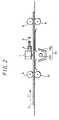
- FIG. 2 is a view of a portion in the vicinity of heads of the recording apparatus shown in FIG. 1, as viewed in cross section.
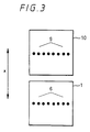
- FIG. 3 is a view illustrative of ink nozzles of the heads of the ink jet recording apparatus.
- a print head 1 having ink nozzles 6 (see FIG. 3) for expelling an ink is reciprocally scanned in the transverse direction (indicated by the arrow x) of a recording medium 2 of paper, plastic film, cloth, or the like while the recording medium 2 is being fed in the direction indicated by the arrow y, for thereby printing an image on the recording medium 2.
- the print head 1 is supported on a shaft 3 and caused to scan the recording medium by a belt 5 which is trained around a head feed motor 4.
- the print head 1 may be of the type which produces an ink expelling pressure by either deforming a so-called piezoelectric element, or boiling an ink with a heating element, or using an electric field.
- the print head 1 has an array of ink nozzles 6 perpendicular to the scanning direction thereof.
- the print head 1 usually has such a plurality of ink nozzles, it may have a single nozzle.
- the recording medium 2 is fed by a sheet feed roller 8 which is rotated by a sheet feed motor 7.
- the serial ink jet printer has a fixing solution head 10 movable in the scanning direction of the print head 1, the fixing solution head 10 having fixing solution nozzles 9 for expelling a fixing solution L to form a dye acceptor layer.
- the fixing solution nozzles 9 are located in positional one-to-one correspondence to the ink nozzles 6.
- the fixing solution head 10 is arranged to expel, from the fixing solution nozzles 9, droplets of the fixing solution L which are of substantially the same shape as ink droplets (having a diameter ranging from 30 to 100 ⁇ m, for example) that are expelled from the ink head 1.
- the serial ink jet printer includes a heater 11 disposed on one side of the recording medium 2 opposite to the fixing solution head 10 and the print head 1 and serving as a drying means for drying the fixing solution L expelled from the fixing solution head 10 and the ink expelled from the print head 1.
- the heater 11 comprises a lamp 11a and a reflecting plate 11b.
- the drying means may not necessarily be required in this embodiment, but may be employed if necessary when the rate at which the fixing solution L and the ink dry is too low. In FIG. 2, the drying means is positioned such that the heater 11 is disposed directly below the print head 1. However, the heater 11 may not necessarily be disposed directly below the print head 1.
- the recording apparatus is used as follows: An ink is prepared by mixing 2 parts by weight of a basic dye, 2 parts by weight of glycerin, 6 parts by weight of diethylene glycol, and 30 parts by weight of water.
- a fixing solution L is prepared by charging 90g of montmorillonite into 850 g of an ethanol solvent which contains 10 g of polyvinyl butyral, dispersing the montmorillonite into the ethanol solvent for one day, and then mixing 50 g of an ethanol solvent which contains 10 g of glycerin into the dispersion. The ink and the fixing solution L are then set in the recording apparatus.
- the fixing solution L For printing, droplets of the fixing solution L which are of substantially the same diameter as the fixing solution nozzles 9 of the fixing solution head 10 are expelled from the fixing solution nozzles 9 to print a desired character or a graphic representation on the recording medium or to print a solid blank pattern on the recording medium.
- the fixing solution L permeates the fibers of the recording medium 2 which may be made of paper or the like, and is dried, whereupon the montmorillonite contained in the fixing solution L is attached near to the surface of the recording medium 2.
- the basic dye contained as dye ions in the ink and the water as a solvent are quickly transferred between layers of the montmorillonite as an intercalation compound, and an exchange between dye cations (dye ions) and intercalation positive ions (intercalation ions), i.e., an intercalation, occurs, causing the dye to be trapped between the layers of the montmorillonite.
- the dye trapped between the layers of the montmorillonite is combined with the montmorillonite by an ionic bond, resulting in a chemically highly stable state.
- FIG. 5 is a cross-sectional view of the recording medium 2, showing the manner in which printing is carried out by fixing and holding the ink as described above.
- a dye acceptor layer composed of the intercalation compound by the fixing solution.
- the attached dye is prevented from being eluted from or swelling between the layers in the presence of water or a organic solvent, so that the water resistance of an image that is formed by the dye is greatly increased. Furthermore, the light resistance of the image is also highly increased because the dye trapped between the layers is shielded from direct exposure to external light.
- the ink may comprise an acid dye or a direct dye
- the fixing solution may comprise hydrotalcite.
- the acid dye or the direct dye is quickly transferred between layers of the hydrotalcite, and an exchange between dye anions and intercalation negative ions, i.e., an intercalation, takes place.
- a desired character or image may be printed with the ink and then with the fixing solution, rather than being printed with the fixing solution and then with the ink as described above.
- the rate at which the fixing solution L and the ink dry may be increased, if necessary, by the heater 11.
- the rate at which the fixing solution L and the ink dry may be increased by heating the recording medium 2 either in advance of printing or subsequent to printing.
- FIG. 6 is a view showing in its entirety an ink jet recording apparatus in its entirety according to another embodiment of the present invention, the ink jet recording apparatus comprising a dye acceptor layer forming means according to the present invention.
- the recording apparatus according to this embodiment includes a print head 1 having ink nozzles 6 and a fixing solution head 10 having fixing solution nozzles 9, the print head 1 and the fixing solution head 10 being staggered in an auxiliary scanning direction.
- the other details of the recording apparatus according to this embodiment are identical to those of the recording apparatus according to the embodiment shown in FIG. 1.
- the print head 1 and the fixing solution head 10 may thus be switched around in position, and are not limited to any particular positions. Therefore, the print head 1 and the fixing solution head 10 in the recording apparatus according to the embodiments shown in FIGS. 1 and 6 may be switched around in position.
- the fixing solution head 10 may be arranged as shown in the perspective view of FIG. 7.
- the fixing solution head 10 has a single fixing solution nozzle 9, and a spray of fixing solution L (composed of droplets having a diameter of several ⁇ m or less, for example) is ejected (sprayed) from the fixing solution nozzle 9 by a solution spray device (not shown) that is actuated by a drive source which employs an electric field, heat, pressure, or the like.
- the fixing solution L is sprayed in a conical shape from the fixing solution nozzle 9, and a circular pattern (shown hatched in FIG. 7) of the fixing solution D which is formed on the recording medium 2 by being thus sprayed covers a range in which the ink expelled from the array of ink nozzles 6 is attached to the recording medium 2 as shown in FIG. 8.
- the recording apparatus according to the embodiment shown in FIG. 7 is shown in side elevation in FIG. 9 as viewed from the fixing solution head 10.
- the fixing solution L is sprayed from the fixing solution nozzle 9 and attached to the recording medium 2 along each line thereon.
- the fixing solution L is applied in a thin layer uniformly without irregularities to the recording medium 2, variations (irregularities) of the thickness of the recording medium 2 which are produced by the attached fixing solution are reduced. Furthermore, the amount of the fixing solution L which is used is also reduced.
- the print head 1 does not print one line in one cycle, but prints one line in a plurality of cycles, i.e., if a line feed interval or pitch corresponds to one of the eight ink nozzles 6 shown in FIG. 7 and hence one dot is printed in eight superposed cycles, then the fixing solution nozzle 9 of the fixing solution head 10 sprays the fixing solution L only in the first scanning stroke, for example, of eight scanning strokes of the print head 1 which are carried out per line.
- the fixing solution L is sprayed in a circular pattern in each scanning stroke of the print head 1 and the fixing solution head 10 in order to cover the range in which the ink is expelled from the ink nozzles 6, as shown in FIG. 8, then the fixing solution L is coated in many superposed layers on the recording medium 2 in the scanning direction of the print head 1 and the fixing solution head 10.
- the fixing solution is sprayed onto the recording medium 2 at areas where no printing is effected.
- zones where one line starts and ends contain areas where no printing is effected with the fixing solution L being left applied in semicircular patterns.
- the fixing solution head 10 may be arranged as shown in FIG. 10.
- the fixing solution head 10 has a fixing solution nozzle 9 defined in the form of an oblong hole.
- the fixing solution nozzle 9 sprays a fixing solution L in a substantially minimum pattern surrounding the range in which the ink expelled from all the ink nozzles 6 is attached to the recording medium 2.
- the fixing solution nozzle 9 may be of a vertically elongate shape such as a rectangular shape or a linear shape, rather than the shape of an oblong hole.
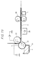
- FIG. 12 shows yet still another arrangement of the fixing solution head 10.
- the fixing solution head 10 has fixing solution nozzles 9 defined therein at positions that are held in positional one-to-one corresponding to the ink nozzles of the print head 1.
- the fixing solution nozzles 9 spray a fixing solution L in substantially minimum ranges that surround areas in which the ink expelled from the respective ink nozzles 6 is attached to the recording medium 2, i.e., respective dots.
- the fixing solution L may be sprayed from all the fixing solution nozzles 9 at all times. However, the fixing solution L may be sprayed selectively from only those of the fixing solution nozzles 9 which correspond to those ink nozzles 6 that expel the ink.
- the fixing solution L is also sprayed from first, third, and eighth fixing solution nozzles 9 as counted from above.
- the fixing solution L is applied to only those areas where printing is effected by the print head 1, as shown in FIG. 15, so that the amount of the fixing solution L used is greatly reduced.
- the ranges where the sprayed fixing solution L is attached to the recording medium 2 may be adjusted by varying the shape and size of the spray ports of the fixing solution nozzles 9 or the pressure under which the fixing solution L is sprayed.
- the ranges may also be adjusted by varying the distance between the fixing solution head 10 and the recording medium 2 or tapering inner side surfaces of the fixing solution nozzles 9.
- the sequence in which the ink and the fixing solution L are applied and the positions of the print head 1 and the fixing solution head 10 are not limited to any particular configuration, as is the case with the embodiments shown in FIGS. 1 through 3 and 6.
- the fixing solution L was produced as follows: 75 g of synthetic smectite (tradename "SWN” manufactured by Coop Chemical Co. Ltd.) was charged into 400 g of an ethanol solution containing 25 g of polyvinyl butyral (tradename "BL-1” manufactured by Sekisui Chemical Co., Ltd.), and dispersed therein by a roll mill for two days. Then, 150 g of an ethanol solution containing 30 g of diethylene glycol was added to the dispersion, and dispersed therein for one day, thereby producing a fixing solution L.
- SWN synthetic smectite
- BL-1 polyvinyl butyral
- the ink to be used in the recording apparatus was prepared according to a composition as follows:
- FIG. 16 is a view showing in its entirety an ink jet recording apparatus according to still another embodiment of the present invention.
- the ink jet recording apparatus according to this embodiment comprises a serial ink jet printer having a dye acceptor layer forming means according the present invention.
- expelling the term has a wide sense including spraying
- the fixing solution L is coated on the recording medium 2 by a coating roller 13 to form a dye acceptor layer on the recording medium 2.
- the recording apparatus shown in FIG. 16 comprises a fixing solution coating section A, a drying section B, and a printing section C.
- the fixing solution coating section A has a solution reservoir 12 for holding a fixing solution L therein, a coating roller 13 for coating the fixing solution L on a recording medium 2, and a counter-roller 14 disposed opposite to the coating roller 13.
- the drying section B has an oven 17 comprising a heater 15 and a reflecting plate 16.
- the printing section C has a print head 1 for expelling an ink.
- a fixing solution L is placed in the solution reservoir 12 in advance.
- the coating roller 13 is uniformly wetted with the fixing solution L.
- the fixing solution L on the coating roller 13 is transferred onto the recording medium 2 which is now uniformly wetted with the fixing solution L.
- the recording medium 2 that is coated with the fixing solution L is fed through guides 18 into the drying section B in which the recording medium 2 is dried by the oven 17, thus forming a dye acceptor layer X on the recording medium 2.
- an ink is ejected from the print head 1 to form an image on the recording medium 2 in the same manner as described above with respect to the recording medium according to the embodiment shown in FIGS. 1 through 3.
- the fixing solution L may be coated on the recording medium 2 after it is printed by the ink, rather than printing the recording medium 2 after it is coated with the fixing solution L.
- the oven 17 is positioned on the same side of the recording medium 2 as the print head 1, the oven 17 may be positioned on the opposite side of the recording medium 2.
- the oven 17 may be replaced with a heat roller or the like.
- the drying section B may be dispensed with depending on the rate at which the fixing solution L dries.
- FIG. 17 is a view showing an ink jet recording apparatus according to yet still another embodiment of the present invention, the ink jet recording apparatus having a dye acceptor layer forming means for forming a dye acceptor layer using a clay powder M.
- the ink jet recording apparatus comprises, as the dye acceptor layer forming means, a clay powder reservoir 19 for holding a clay powder M, a clay drum 20 for attaching the clay powder electrostatically to a recording medium 2, a powder cutting blade 21 for keeping constant the height of the clay powder M attached to the clay drum 20, a clay attaching roller 22 for charging the recording medium 2 to a potential opposite to that of the clay powder M to attach the clay powder M to the recording medium 2, and fixing rollers 23 for heating the clay powder M attached to the recording medium 2 to fix the clay powder M to the recording medium 2.
- the fixing rollers 23 may have halogen lamps or the like disposed therein for heating the clay powder M to a temperature ranging from about 150 to 200°C.
- a print head 1 having ink jet nozzles is disposed subsequently to the dye acceptor layer forming means.
- a clay powder M and a carrier are placed in the clay powder reservoir 19. Then, while a bias potential (e.g., - 3 ⁇ - 4 kV) is being applied to the clay drum 20 and a bias potential (e.g., + 3 ⁇ + 4 kV) is being applied to the clay attaching roller 22, the clay drum 20 is rotated to triboelectrically charge the clay powder M and the carrier to respective opposite polarities.
- the clay powder M on the clay drum 20 is attached under electrostatic forces to the recording medium 2 that has been charged to the polarity opposite to the clay powder M by the clay attaching roller 22.
- the clay powder M attached to the recording medium 2 is heated by the fixing rollers 23 and hence fixed to the recording medium 2.
- a dye acceptor layer X composed of an intercalation compound is formed on the recording medium 2.
- an ink is expelled from the print head 1 to form an image on the recording medium 2 with the dye acceptor layer X formed thereon.
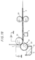
- FIG. 18 shows a modification of the ink jet recording apparatus shown in FIG. 17.
- the clay powder M is attached to the recording medium 2 and before it is fixed by the fixing rollers 23, an image is formed on the recording medium 2 with an ink by the print head 1. Thereafter, the clay powder M is fixed by the fixing rollers 23, forming a dye acceptor layer X.
- the other details of the ink jet recording apparatus shown in FIG. 18 except that the fixation of the clay powder M and the formation of the ink image are switched around are identical to those of the ink jet recording apparatus shown in FIG. 17.
- FIG. 19 shows another modification of the ink jet recording apparatus shown in FIG. 17.
- the ink jet recording apparatus shown in FIG. 19 employs a clay liquid N instead of the clay powder M employed in the ink jet recording apparatus shown in FIG. 17.
- the ink jet recording apparatus shown in FIG. 19 has a clay liquid reservoir 24 which holds a clay liquid N that is prepared by dispersing a clay powder composed of an epoxy resin binder and an intercalation compound into an insulating solvent such as of dibutyl phthalate or the like.
- the clay liquid N is triboelectrically charged to a potential ranging from - 3 ⁇ - 4 kV, for example, while a bias potential (e.g., + 300 ⁇ + 400 V) that is of an opposite polarity to the clay liquid N is being applied to the clay drum 20 and a bias potential ranging from + 3 ⁇ + 4 kV, for example, is being applied to the clay attaching roller 22.
- a bias potential e.g., + 300 ⁇ + 400 V
- + 3 ⁇ + 4 kV for example
- the recording medium 2 to which the clay liquid N is attached is heated to a temperature ranging from 50 to 200°C by a heater 25, whereupon the clay liquid N is dried and fixed to the recording medium 2, thus forming a dye acceptor layer X on the recording medium 2.
- the recording medium 2 with the dye acceptor layer X thus formed thereon is fed by sheet feed rollers 26 to a subsequent printing section where an image is formed on the recording medium 2 with an ink by the print head 1.
- FIG. 20 is a view showing in its entirety an ink jet recording apparatus according to a yet still further embodiment of the present invention.
- a dye acceptor layer X formed in a ribbon P is thermally transferred onto a recording medium 2 to form the dye acceptor layer X on the recording medium 2.
- FIG. 21A and 21B are views illustrative of the manner in which the dye acceptor layer X formed in the ribbon P is thermally transferred onto the recording medium 2.
- the ribbon P for use in the ink jet recording apparatus comprises a successively laminated structure composed of a base film 27, a dye acceptor layer X, and an adhesive layer 28. It was possible to produce the ribbon P as follows:
- a PET film having a thickness of 6 ⁇ m and including a surface processed for releasability was prepared as a base film.
- the processed surface of the PET film was coated with a composition for forming a dye acceptor layer by a wire bar, and dried with hot air at 120°C for five minutes, thereby forming a dye acceptor layer in the form of a solid film having a thickness of 5 ⁇ m.
- an adhesive composed of 2 parts by weight of vinylidene chloride - acrylonitrile copolymer (manufactured by Aldrich Corp.) and 20 parts by weight of methyl ethyl ketone was prepared, and coated on the dye acceptor layer using a bar coater, to a wet thickness of 50 ⁇ m. The coated adhesive was then dried into an adhesive layer.
- the ink jet recording apparatus shown in FIG. 20 comprises, as a dye acceptor layer forming means, a ribbon holding means (not shown) for holding a ribbon P in the recording apparatus, a heat roller 29 for heating the ribbon P which is drawn from the ribbon holding means, a cooling roller 30 for cooling the ribbon P after a dye acceptor layer X is thermally transferred, a peeling roller 31 for peeling a base film 27 of the ribbon P from the dye acceptor layer X, and platen rollers 32 through 34 for pressing a recording medium 2 against the ribbon P.
- the ink jet recording apparatus also has a serial print head 1 disposed subsequently to the dye acceptor layer forming means.
- the ink jet recording apparatus shown in FIG. 20 was operated to form an image on a recording medium 2 of synthetic paper having a thickness of 100 ⁇ m as follows:
- the ribbon P and the recording medium 2 were set in the recording apparatus such that the adhesive layer 28 of the ribbon P confronted the recording medium 2.
- the ribbon P and the recording medium 2 were fed at a rate of 3 cm/second between the heat roller 29 heated to 120°C and the platen roller 32, so that the ribbon P and the recording medium 2 were heated and pressed, bonding the dye acceptor layer X of the ribbon P to the recording medium 2 through the adhesive layer 28.
- the dye acceptor layer X was bonded to the recording medium 2 over its full width (in a direction perpendicular to the direction of feed of the recording medium 2).
- the ribbon P and the recording medium 2 were cooled to room temperature by the cooling roller 30, and the base film 27 of the ribbon P was peeled off the dye acceptor layer X bonded to the recording medium 2 by the peeling roller 31.
- the dye acceptor layer X was thermally transferred from the ribbon P to the recording medium 2 as shown in FIG. 21B.
- the produced image was immersed in water for one day and night, and thereafter the surface of the image was pressed strongly and rubbed by a finger. However, no dye was eluted, and no dye acceptor layer was separated from the dye acceptor layer, indicating that the image had good fixability. Furthermore, the image was exposed to Xe light (90000 kJ/m2) at 30°C and 65 % RH. The remaining dye of each of the colors was 80 % or greater, indicating that the image exhibited a high level of light resistance comparable with silver-salt photographs.
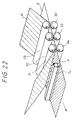
- FIG. 22 shows a modification of the ink jet recording apparatus shown in FIG. 20.
- the ink jet recording apparatus shown in FIG. 22 after a dye acceptor layer X has been formed on a recording medium 2 by thermal transfer, an image is formed on the recording medium 2 by a line print head 1L.
- the other details of the ink jet recording apparatus shown in FIG. 22 are identical to those of the ink jet recording apparatus shown in FIG. 20. Since the ink jet recording apparatus shown in FIG. 20 allows the dye acceptor layer X to be easily formed on the recording medium over its full width, it also may have a line print head 1L as is the case with the ink jet recording apparatus shown in FIG. 22.
- FIG. 23 shows an ink jet recording apparatus in which a dye acceptor layer X is formed on a recording medium 2 using a ribbon P as with the ink jet recording apparatus shown in FIG. 20.
- the ribbon P is wound in a ribbon cassette 35 which is mounted on a cassette holder 36 that has a heater (not shown), and the dye acceptor layer X of the ribbon P drawn from the ribbon cassette 35 can be thermally transferred to the recording medium 2 by the heater of the cassette holder 36.
- the ink jet recording apparatus shown in FIG. 23, therefore, makes it possible to form a dye acceptor layer only in a certain print region, and hence can be reduced in size.
- the cassette holder 36 which holds the ribbon cassette 35 that stores the ribbon P may be integral with a serial print head 1 for achieving a further reduction in the size of the ink jet recording apparatus.
- the print head may comprise a line print head.
- FIG. 24 shows an ink jet recording apparatus in its entirety in which a fixing agent Q that contains an intercalation compound dispersed in wax and is solid at normal temperature is melted and coated on a recording medium 2 thereby to form a dye acceptor layer on the recording medium 2.
- FIG. 25 is a cross-sectional view of the ink jet recording apparatus.
- the ink jet recording apparatus shown in FIG. 24 comprises, as a dye acceptor layer forming means, a solid fixing agent cassette 37 for holding a solid fixing agent Q such than the solid fixing agent Q is pressed against a heat roller 38, a heat roller 38 for melting the solid fixing agent Q with heat and coating the melted solid fixing agent Q on a recording medium 2 upon rotation in the direction indicated by the arrow, and a pressing roller 39 positioned opposite to the heat roller 38 and rotatable in the direction indicated by the arrow for pressing the recording medium 2.
- the ink jet recording apparatus shown in FIG. 24 also has a serial print head 1 subsequently to the dye acceptor layer forming means.
- the ink to be used in the recording apparatus was prepared according to a composition as follows:
- an image was formed on a sheet of plain paper by the ink jet recording apparatus shown in FIG. 24.
- the heat roller 38 was set to a temperature (80 ⁇ 120°C) equal to or higher than the melting points of the solid fixing agents, and the linear pressure between the rollers was set to 3 kg/cm.
- the heat roller 38 and the pressing roller 39 were rotated at a speed of 10 mm/s. As a result, an image was formed well on a dye acceptor layer which was formed using either the solid fixing agent Q-1 or the solid fixing agent Q-2.
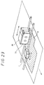
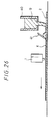
- FIG. 26 is a cross-sectional view of an ink jet recording apparatus according to a further embodiment of the present invention.
- the ink jet recording apparatus melts a solid fixing agent Q and coats the melted solid fixing agent Q on a recording medium 2 to form a dye acceptor layer thereon.
- the solid fixing agent Q is melted and coated on the recording medium 2 as follows:
- the solid fixing agent Q is placed in a solid fixing agent cassette 40 with a heater, and the solid fixing agent Q which is melted is discharged from the bottom of the solid fixing agent cassette 40 onto the recording medium 2 which is being fed in the direction indicated by the arrow.
- the fixing agent Q on the recording medium 2 is uniformly squeezed into a dye acceptor layer X having a predetermined thickness by a squeezer 41.
- An image is thereafter printed on the dye acceptor layer X by a print head 1.
- the linear pressure of the squeezer 41 which depends on the viscosity of the solid fixing agent Q in a melted state, may be of about 0.5 kg/cm, for example.
- the ink jet recording apparatus may be arranged as a serial printer, a line head printer, or the like in the embodiment in which the fixing solution is expelled or sprayed from the nozzle or nozzles to form a dye acceptor layer on the recording medium 2, the embodiment in which the fixing solution is coated by a coating roller to form a dye acceptor layer on the recording medium 2, the embodiment in which the clay powder is applied to form a dye acceptor layer on the recording medium 2, the embodiment in which a dye acceptor layer is formed on the recording medium 2 by being thermally transferred from the ribbon, and the embodiment in which the solid fixing agent is melted and coated to form a dye acceptor layer on the recording medium 2.
- a solvent having a low vapor pressure as a clogging inhibitor
- Such a solvent for use as a clogging inhibitor should preferably:
- Such a solvent (clogging inhibitor) may be a nitrogen-containing solvent such as a glycol such as ethylene glycol, propylene glycol, diethylene glycol, triethylene glycol, tetraethylene glycol, polyethylene glycol, or glycerin, a glycol ether such as ethylene glycol monomethyl ether, ethylene glycol monoethyl ether, ethylene glycol monobutyl ether, methyl Carbitol, ethyl Carbitol, butyl Carbitol, ethyl Carbitol acetate, diethyl Carbitol, triethylene glycol monomethyl ether, triethylene glycol monoethyl ether, or propylene glycol monomethyl ether, an amide such as triethanolamine, formamide, or dimethyl formamide, or a pyrrolidone such as N-methyl-2-pyrrolidone.
- a glycol such as ethylene glycol, propylene glycol, diethylene glycol, triethylene glycol,
- the content of the slogging inhibitor should generally be 3 % or more of the total weight of the fixing solution, and preferably be in the range of from 3 % to 90 % of the total weight of the fixing solution.
- the dye acceptor layer is formed substantially at the same time that an image is printed on the recording medium 2.
- the dye acceptor layer may be formed in advance on the recording medium 2.
- a fixing solution with a solid content of a lower proportion i.e., a fixing solution having a lower viscosity
- a fixing solution composed, for example, of: intercalation compound: smectite 150 g binder resin: butyral 100 g solvent: ethanol 900 g with a solid content having a proportion of 21.7 % is used.
- a fixing solution composed, for example, of: intercalation compound: smectite 75 g binder resin: butyral 25 g glycol: ethylene glycol 30 g solvent: ethanol 520 g with a solid content having a proportion of 15.4 % is used.
- the same ink can be used.
- the ink jet recording apparatus can form images of excellent water resistance and light resistance.
Abstract
Description
- The present invention relates to an ink jet recording apparatus having a means for forming on a recording medium a dye acceptor layer which fixes and holds a dye by way of an intercalation.
- One of the methods of outputting images such as documents, graphic representations, or the like generated by personal computers or the like onto recording mediums such as sheets of paper, OHP films, or the like is known as an ink jet recording process.
- In the ink jet recording process, an ink in the form of a solution is ejected from a nozzle toward a recording medium by a drive source which employs an electric field, heat, pressure, or the like for thereby forming an image on the recording medium. The ink jet recording process is advantageous in that it produces a low level of noise, requires a low running cost, can form images on sheets of ordinary paper, and does not discharge a waste material such as ink ribbons. Therefore, ink jet recording apparatus have been finding widespread use in recent years as recording apparatus for office or personal use.
- The ink jet recording process is, however, disadvantageous in that images formed on recording mediums by this process have poor fixability properties, particularly water resistance and light resistance.
- The reasons for such poor fixability properties are as follows: Generally, an ink for use in ink jet recording is composed of a water-soluble dye. For printing using such an ink, the ink is ejected toward a recording medium, and after the ink has been dried, its water-soluble dye remains on the recording medium and is held thereon by the van der Waals forces or hydrogen bonding for thereby fixing an image to the recording medium. Therefore, when a solvent such as water or the like which has a large affinity for the water-soluble dye is supplied to the recorded image, the dye is eluted, causing the image to blur.
- The dye also moves, causing the image to blur, when the water-soluble dye which forms the image on the recording medium is supplied with thermal or light energy that is large enough to cancel out the van der Waals forces or hydrogen bonding between the dye and the recording medium. Furthermore, upon exposure of the dye which forms the image to light such as ultraviolet radiation or the like, the molecules of the dye itself are destroyed, causing the image to be faded, discolored, or lowered in density. Therefore, images formed by the dye are also of low light resistance.
- The water resistance of images formed according to the ink jet recording process can be improved by using a recording medium of sized paper or a recording medium coated with a resin. The resin to be coated on the recording medium comprises a hydrophilic resin for allowing image to be formed by a water-soluble dye. Attempts have also been made to improve the light resistance of images formed according to the ink jet recording process by selecting a dye having a certain basic skeleton or introducing a certain substituent group into a side chain of dye molecules thereby to limit the molecular structure of the dye.
- If the recording medium of sized paper is used to improve the water resistance of images formed according to the ink jet recording process, then it takes a long time to fix the ink to the recording medium as the recording medium has low ink absorption.
- If the recording medium coated with a hydrophilic resin is used, then it has good ink absorption, but tends to form ink dots of large diameter or ink dots having blurred edges. Since the resin coated on the recording medium is hydrophilic, it essentially is not sufficiently effective to improve the water resistance of recorded images. Another problem of the recording medium coated with a hydrophilic resin is that it impairs the basic advantage of the ink jet recording process that sheets of ordinary paper can be used as the recording medium.
- The attempts to limit the molecular structure of the dye for improved light resistance have not yet been sufficiently effective.
- The present invention has been made to solve the above problems of the prior art.
- It is an object of the present invention to form images of high water and light resistance on sheets of ordinary paper according to an ink jet recording process.
- The inventor has found that in order to achieve the above object, a dye acceptor layer composed of an intercalation compound for holding a dye by way of an intercalation may be formed on a recording medium such as of plain paper, that a means for forming such a dye acceptor layer may be included in an ink jet recording apparatus, that the dye acceptor layer may be formed by expelling or spraying a solution (hereinafter referred to as a fixing solution) containing such an intercalation compound from a nozzle or nozzles, or coating a fixing solution on the recording medium with a coating roller, or electrostatically applying a powder (referred to as a clay powder in this specification) composed of an intercalation compound and a thermoplastic resin to the recording medium, or producing a ribbon having a dye acceptor layer composed of an intercalation compound and formed on a base film and thermally transferring the dye acceptor layer of the ribbon onto the recording medium, or melting a fixing agent which is composed of an intercalation compound and a wax and solid at normal temperature (hereinafter referred to as a solid fixing agent) and coating the melted fixing agent on the recording medium, and has completed the present invention.
- According to the present invention, an ink jet recording apparatus having an ink nozzle for expelling an ink toward a recording medium to form an image thereon is characterized by dye acceptor layer forming means for forming on said recording medium a dye acceptor layer composed of an intercalation compound which fixes and holds a dye of the ink by way of an intercalation.
- The ink jet recording apparatus according the present invention will hereinafter be described in detail.
- In the ink jet recording apparatus according the present invention, an image is fixed on the basis of the formation of an ionic bond caused by an intercalation between a dye in the ink and the intercalation compound of the dye acceptor layer.
- The ink may be prepared by dissolving a dye into an aqueous solvent such as water or the like, and adding, if necessary, a viscosity modifier, a surface tension modifier, a drying inhibitor, and so on to the solution. Any of various inks that have conventionally been used for ink jet recording apparatus may be used.
- An acid dye, a direct dye, a basic dye, or the like may be used without any particular limitations as the dye to be contained in the ink insofar as it can be intercalated into the intercalation compound. For example, a basic dye such as an azo dye having an amine salt or a quaternary ammonium group, a triphenylmethane dye, an azone dye, an oxazine dye, a thiazine dye, or the like may be used. More specifically, a yellow dye such as C.I. basic yellow 1, C.I. basic yellow 2, C.I. basic yellow 11, C.I. basic yellow 13, C.I. basic yellow 14, C.I. basic yellow 19, C.I. basic yellow 21, C.I. basic yellow 25, C.I. basic yellow 28, or C.I.
basic yellow 32 ∼ 36, a magenta dye such as C.I. basic red 1, C.I.basic red 2, C.I. basic red 9, C.I.basic red 12 ∼ 15, C.I. basic red 17, C.I. basic red 18, C.I.basic red 22 ∼ 24, C.I. basic red 27, C.I. basic red 29, C.I. basic red 32, C.I.basic red 38 ∼ 40, C.I.basic violet 7, C.I.basic violet 10, C.I.basic violet 15, C.I.basic violet 21, C.I.basic violet 25 ∼ 28, a cyan dye such as C.I. basic blue 1, C.I. basic blue 3, C.I. basic blue 5, C.I. basic blue 7, C.I. basic blue 9, C.I. basic blue 19, C.I. basic blue 21, C.I. basic blue 22, C.I. basic blue 24 ∼ 26, C.I. basic blue 28, C.I. basic blue 29, C.I. basic blue 40, C.I. basic blue 41, C.I. basic blue 44, C.I. basic blue 45, C.I. basic blue 47, C.I. basic blue 54, C.I. basic blue 58 ∼ 60, C.I. basic blue 64 ∼ 68, or C.I. basic blue 75, and a black dye such as C.I. basic black 2, or C.I. basic black 8 may be used. - The dye acceptor layer to be formed on the recording medium in order to fix the above dye should preferably be composed of a high-polymer (macro-molecular) organic intercalation compound having exchangeable negative ions between layers if the ink is composed of an acid dye or a direct dye, or a high-polymer organic intercalation compound having exchangeable positive ions between layers if the ink is composed of a basic dye.
- The intercalation compound has a laminar structure and holds interlaminar water and exchangeabie ions between layers. The high-polymer inorganic intercalation compound having exchangeable positive ions between layers which is used if the ink is composed of a basic dye may be natural or synthetic laminar silicate or their sintered material. Typically, it is preferable to use a montmorillonite-group mineral which is one of clay minerals having a 3-octahedral smectite structure and represented by the following formula (1):
(X,Y)₂₋₃Z₄O₁₀(OH₂) ·mH₂O· (W1/3) (1)
where X represents Al, Fe(III), Mn(III), or Co(III), Y represents Mg, Fe(II), Ni, Zn, or Li, Z represents Si or Al, W represents K, Na, or Ca, H₂O represents interlaminar water, and m represents an integer. - Depending on the combination of X and Y and the number of substitutions, the montmorillonite-group mineral may be a natural or synthetic mineral such as montmorillonite, magnesia montmorillonite, iron montmorillonite, iron magnesia montmorillonite, beidellite, aluminianbeidellite, nontronite, aluminiannontronite, saponite, aluminiansaponite, hectorite, sauconite, or the like. Materials represented by the above formula (1) with the OH group replaced with fluorine may also be used.
- Other than the montmorillonite-group mineral represented by the above formula (1), a mica-group mineral such as sodium silicic mica, sodium teniorite, lithium teniorite, or the like may also be used as an intercalation compound.
- The high-polymer inorganic intercalation compound having exchangeable negative ions between layers which is used if the ink is composed of an acid dye or a direct dye may be hydrotalcite or the like.
- Depending on the type of the ink used, the dye acceptor layer to be formed on the recording medium may contain an intercalation compound having exchangeable positive ions, such as montmorillonite or the like, or an intercalation compound having exchangeable negative ions, such as hydrotalcite or the like, or both of these intercalation compounds.
- The present invention is not limited to any particular method of forming a dye acceptor layer composed of such an intercalation compound. In an example of such a method, a fixing solution, i.e., a solution containing an intercalation compound, is prepared, and ejected from a solution nozzle onto a recording medium to form a dye acceptor layer.
- The fixing solution may be expelled from the solution nozzle as droplets having the same shape as ink droplets expelled from ink nozzles, or may be atomized and expelled (sprayed) from the solution nozzle.
- Specifically, the solution nozzle may comprise a single nozzle, and the fixing solution may be sprayed from the nozzle in a range covering an image that will be formed by expelling the ink from the ink nozzles onto the recording medium.
- Alternatively, the solution nozzle may comprise an array of nozzles, and fixing solution may be sprayed from the nozzles in a range of an image that will be formed by expelling the ink from the ink nozzles onto the recording medium. If the ink nozzle comprises a plurality of nozzles arranged in the same manner as the nozzles of the solution nozzle, then the nozzles of the solution nozzle are selectively operable to spray the fixing solution in a manner to correspond to those of the nozzles of the ink nozzle which expel the ink.
- The solution nozzle may also comprise a nozzle in the form of an oblong hole for spraying the fixing solution in a range covering an image that will be formed by expelling the ink from the ink nozzles onto the recording medium.
- The fixing solution may be prepared by mixing an intercalation compound with an aqueous solvent such as water, alcohol, or the like, and adding, if necessary, an additive such as a binder resin, a dispersion stabilizer, an ultraviolet light absorber, or a fluorescent brightener.
- Alternatively, a powder (clay powder) composed of an intercalation compound and a thermoplastic resin may be prepared, and a dye acceptor layer may be formed on the recording medium using such a clay powder.
- The clay powder may be prepared by dispersing a powdery intercalation compound into a thermoplastic resin binder, and converting the dispersion into a fine powder. The thermoplastic resin binder into which the powdery intercalation compound is to be dispersed may be composed of a styrene-acryl copolymer, polyester, an epoxy resin, or the like, for example.
- As the thermoplastic resin to be used as the binder resin, it is preferable not to contain a group which will impair an intercalation between an intercalation compound and a dye, e.g., an ammonium group or the like which is more likely to be held between layers than is the dye.
- Since use of a certain intercalation compound and a certain binder resin in combination makes it possible to produce a highly transparent dye acceptor layer, the intercalation compound and the binder resin should be selected depending on the degree of transparency which is required by the recording medium after an image has been formed thereon.
- A dye acceptor layer may be formed on a recording medium using a clay powder in the same manner as a toner is applied to a recording medium to form an image thereon according to the electrophotographic process. Specifically, the clay powder may be electrostatically attracted to the recording medium, and then heated so as to be fixed to the recording medium. Alternatively, a clay powder may be dispersed in an insulating solvent such as of dibutyl phthalate or the like, thus producing a clay liquid, and the clay liquid may be attracted to a recording medium in the same manner as a liquid toner image is developed according to the electrophotographic process, for thereby forming a dye acceptor layer.
- A dye acceptor layer composed of an intercalation compound may be formed on a recording medium by producing a ribbon having a dye acceptor layer composed of an intercalation compound and a binder resin and formed on a base film made of polyethylene terephthalate or the like, and thermally transferring the dye acceptor layer of the ribbon onto the recording medium.
- To the dye acceptor layer of the ribbon, there may be added a plasticiser for controlling the glass transition point Tg thereof insofar as it does not impair the transferability thereof to the recording medium. Furthermore, an additive for controlling the water repellancy, an ultraviolet light absorber for improving the light resistance, a fluorescent brightener, etc. may also be added. In the production of the ribbon, because use of a certain intercalation compound and a certain binder resin in combination makes it possible to produce a highly transparent dye acceptor layer, the intercalation compound and the binder resin should be selected depending on the degree of transparency which is required by the recording medium after an image has been formed thereon.
- If the dye acceptor layer is thermally transferred from the ribbon to form the dye acceptor layer on the recording medium, then the recording medium should preferably be of such a nature as to be prevented from being deformed with the heat when the dye acceptor layer is thermally transferred thereonto.
- A dye acceptor layer composed of an intercalation compound may also be formed on a recording medium by preparing a fixing agent which is composed of an intercalation compound and a wax and which is solid at normal temperature (solid fixing agent) and coating the melted fixing agent on the recording medium. The wax which serves a binder for the intercalation compound may be carnauba wax, paraffin wax, high-polymer polyethylene glycol, or the like, for example.
- In the preparation of a solid fixing solution from a wax and an intercalation compound, depending on the type of the wax used, the ability of the produced solid fixing solution to absorb the ink would be lowered if the proportion of the wax were too high, and the solid fixing agent would not be solid at normal temperature if the proportion of the wax were too low. Therefore, the ratios of the wax and the intercalation compound are determined such that the produced solid fixing solution can well absorb the ink and becomes solid at normal temperature. For example, if a solid fixing agent is prepared from carnauba wax and synthetic smectite whose ratios are 1 : 1, then the produced solid fixing solution is hydrophilic and has a good ability to absorb an aqueous ink. Increasing the ratio of the carnauba wax makes the solid fixing agent more hydrophilic. The solid fixing solution can be obtained at room temperature with a ratio of the carnauba wax and synthetic smectite up to about 1 : 5. If a solid fixing agent is prepared from high-polymer polyethylene glycol and synthetic smectite, then the ability of the produced solid fixing solution to absorb the ink is not reduced by an increase in the proportion of the high-polymer polyethylene glycol.
- In the ink jet recording apparatus according to the present invention, an ink is expelled from the ink nozzles to form an image on the recording medium, and a dye acceptor layer composed of an intercalation compound is formed on the recording medium by the dye acceptor layer forming means.
- When the ink image is formed on the dye acceptor layer which is formed on the recording medium by the dye acceptor layer forming means or the dye acceptor layer is formed on the ink image by the dye acceptor layer forming means, dye ions in the ink are transferred, together with water and alcohol in the ink, between layers of the intercalation compound of the dye acceptor layer, and exchanged (intercalated) with interlaminar ions that have been present between the layers, so that the dye ions are firmly held between the layers by an ionic bond with the intercalation compound.
- The dye thus held between the layers will not be eluted even when supplied with water or the like. Consequently, the image produced by the ink jet recording apparatus according to the present invention has increased water resistance. The dye trapped between the layers is not directly exposed to external light, and hence the light resistance of the image formed by the ink jet recording apparatus according to the present invention is highly increased.
- A highly transparent dye acceptor layer can be formed on a recording medium if a certain intercalation compound and a certain binder resin are used in combination. Therefore, a preferable image can be formed on a recording medium that is required to be transparent for OHP use, for example.
-
- FIG. 1 is a view showing in its entirety an ink jet recording apparatus according to an embodiment of the present invention;
- FIG. 2 is a cross-sectional view of a portion in the vicinity of heads of the ink jet recording apparatus according to the embodiment shown in FIG. 1;
- FIG. 3 is a view illustrative of ink nozzles of the heads of the ink jet recording apparatus according to the embodiment shown in FIG. 1;
- FIG. 4 is a view illustrative of an intercalation;
- FIG. 5 is a view showing the manner in which an ink is fixed and held by way of an intercalation;
- FIG. 6 is a view showing in its entirety an ink jet recording apparatus according to another embodiment of the present invention;
- FIG. 7 is a perspective view showing another arrangement of a
fixing solution head 10; - FIG. 8 is a view illustrative of a range of a fixing solution sprayed from the fixing
solution head 10 shown in FIG. 7; - FIG. 9 is a side elevational view of the fixing
solution head 10 shown in FIG. 7; - FIG. 10 is a perspective view showing still another arrangement of the fixing
solution head 10; - FIG. 11 is a view illustrative of a range of a fixing solution sprayed from the fixing
solution head 10 shown in FIG. 10; - FIG. 12 is a perspective view showing yet still another arrangement of the fixing
solution head 10; - FIG. 13 is a view illustrative of a range of a fixing solution sprayed from the fixing
solution head 10 shown in FIG. 12; - FIG. 14 is a view illustrative of the manner in which the
fixing solution head 10 shown in FIG. 12 operates; - FIG. 15 is a view illustrative of the manner in which the
fixing solution head 10 shown in FIG. 12 operates; - FIG. 16 is a view showing in its entirety an ink jet recording apparatus according to still another embodiment of the present invention;
- FIG. 17 is a view showing in its entirety an ink jet recording apparatus according to yet still another embodiment of the present invention;
- FIG. 18 is a view showing in its entirety an ink jet recording apparatus according to a further embodiment of the present invention;
- FIG. 19 is a view showing in its entirety an ink jet recording apparatus according to a still further embodiment of the present invention;
- FIG. 20 is a view showing in its entirety an ink jet recording apparatus according to a yet still further embodiment of the present invention;
- FIG. 21A and 21B are views illustrative of the manner in which a dye acceptor layer X formed in a ribbon P is thermally transferred onto a
recording medium 2; - FIG. 22 is a perspective view showing in its entirety an ink jet recording apparatus according to another embodiment of the present invention;
- FIG. 23 is a perspective view showing in its entirety an ink jet recording apparatus according to still another embodiment of the present invention;
- FIG. 24 is a perspective view showing in its entirety an ink jet recording apparatus according to yet still another embodiment of the present invention;
- FIG. 25 is a cross-sectional view of the ink jet recording apparatus according to the embodiment shown in FIG. 24; and
- FIG. 26 is a cross-sectional view of an ink jet recording apparatus according to a further embodiment of the present invention.
- Embodiments of the present invention will hereinafter be described in specific detail with reference to the drawings. Identical reference characters denote identical or equivalent components throughout views.
- FIG. 1 is a view showing in its entirety an ink jet recording apparatus according to an embodiment of the present invention, the ink jet recording apparatus comprising a so-called serial ink jet printer having a dye acceptor layer forming means for discharging a fixing solution L to form a dye acceptor layer. FIG. 2 is a view of a portion in the vicinity of heads of the recording apparatus shown in FIG. 1, as viewed in cross section. FIG. 3 is a view illustrative of ink nozzles of the heads of the ink jet recording apparatus.
- In the serial ink jet printer, as shown in FIGS. 1 and 2, a
print head 1 having ink nozzles 6 (see FIG. 3) for expelling an ink is reciprocally scanned in the transverse direction (indicated by the arrow x) of arecording medium 2 of paper, plastic film, cloth, or the like while therecording medium 2 is being fed in the direction indicated by the arrow y, for thereby printing an image on therecording medium 2. - The
print head 1 is supported on ashaft 3 and caused to scan the recording medium by abelt 5 which is trained around a head feed motor 4. Theprint head 1 may be of the type which produces an ink expelling pressure by either deforming a so-called piezoelectric element, or boiling an ink with a heating element, or using an electric field. As shown in FIG. 3, theprint head 1 has an array ofink nozzles 6 perpendicular to the scanning direction thereof. - While the
print head 1 usually has such a plurality of ink nozzles, it may have a single nozzle. - The
recording medium 2 is fed by asheet feed roller 8 which is rotated by asheet feed motor 7. - In this embodiment, the serial ink jet printer has a
fixing solution head 10 movable in the scanning direction of theprint head 1, the fixingsolution head 10 havingfixing solution nozzles 9 for expelling a fixing solution L to form a dye acceptor layer. The fixingsolution nozzles 9 are located in positional one-to-one correspondence to theink nozzles 6. - The fixing
solution head 10 is arranged to expel, from the fixingsolution nozzles 9, droplets of the fixing solution L which are of substantially the same shape as ink droplets (having a diameter ranging from 30 to 100 µm, for example) that are expelled from theink head 1. - The serial ink jet printer includes a
heater 11 disposed on one side of therecording medium 2 opposite to thefixing solution head 10 and theprint head 1 and serving as a drying means for drying the fixing solution L expelled from the fixingsolution head 10 and the ink expelled from theprint head 1. Theheater 11 comprises alamp 11a and a reflectingplate 11b. The drying means may not necessarily be required in this embodiment, but may be employed if necessary when the rate at which the fixing solution L and the ink dry is too low. In FIG. 2, the drying means is positioned such that theheater 11 is disposed directly below theprint head 1. However, theheater 11 may not necessarily be disposed directly below theprint head 1. - The recording apparatus according to this embodiment is used as follows: An ink is prepared by mixing 2 parts by weight of a basic dye, 2 parts by weight of glycerin, 6 parts by weight of diethylene glycol, and 30 parts by weight of water. A fixing solution L is prepared by charging 90g of montmorillonite into 850 g of an ethanol solvent which contains 10 g of polyvinyl butyral, dispersing the montmorillonite into the ethanol solvent for one day, and then mixing 50 g of an ethanol solvent which contains 10 g of glycerin into the dispersion. The ink and the fixing solution L are then set in the recording apparatus. For printing, droplets of the fixing solution L which are of substantially the same diameter as the fixing
solution nozzles 9 of the fixingsolution head 10 are expelled from the fixingsolution nozzles 9 to print a desired character or a graphic representation on the recording medium or to print a solid blank pattern on the recording medium. The fixing solution L permeates the fibers of therecording medium 2 which may be made of paper or the like, and is dried, whereupon the montmorillonite contained in the fixing solution L is attached near to the surface of therecording medium 2. - Then, droplets of the ink which are of substantially the same diameter as the
ink nozzles 6 of theprint head 1 are expelled from theink nozzles 6 to print a desired character or a graphic representation on the recording medium. As shown in FIG. 4, the basic dye contained as dye ions in the ink and the water as a solvent are quickly transferred between layers of the montmorillonite as an intercalation compound, and an exchange between dye cations (dye ions) and intercalation positive ions (intercalation ions), i.e., an intercalation, occurs, causing the dye to be trapped between the layers of the montmorillonite. The dye trapped between the layers of the montmorillonite is combined with the montmorillonite by an ionic bond, resulting in a chemically highly stable state. - FIG. 5 is a cross-sectional view of the
recording medium 2, showing the manner in which printing is carried out by fixing and holding the ink as described above. On the surface of therecording medium 2, there is formed a dye acceptor layer composed of the intercalation compound by the fixing solution. When droplets of an ink (ink droplets) are supplied and attached to the dye acceptor layer, the ink droplets enter between the layers of the intercalation compound by way of an intercalation. - Therefore, the attached dye is prevented from being eluted from or swelling between the layers in the presence of water or a organic solvent, so that the water resistance of an image that is formed by the dye is greatly increased. Furthermore, the light resistance of the image is also highly increased because the dye trapped between the layers is shielded from direct exposure to external light.
- The ink may comprise an acid dye or a direct dye, and the fixing solution may comprise hydrotalcite. According to such a modification, the acid dye or the direct dye is quickly transferred between layers of the hydrotalcite, and an exchange between dye anions and intercalation negative ions, i.e., an intercalation, takes place.
- In the use of the recording apparatus, a desired character or image may be printed with the ink and then with the fixing solution, rather than being printed with the fixing solution and then with the ink as described above.
- In the use of the recording apparatus, furthermore, the rate at which the fixing solution L and the ink dry may be increased, if necessary, by the
heater 11. The rate at which the fixing solution L and the ink dry may be increased by heating therecording medium 2 either in advance of printing or subsequent to printing. - FIG. 6 is a view showing in its entirety an ink jet recording apparatus in its entirety according to another embodiment of the present invention, the ink jet recording apparatus comprising a dye acceptor layer forming means according to the present invention. The recording apparatus according to this embodiment includes a
print head 1 havingink nozzles 6 and afixing solution head 10 havingfixing solution nozzles 9, theprint head 1 and the fixingsolution head 10 being staggered in an auxiliary scanning direction. The other details of the recording apparatus according to this embodiment are identical to those of the recording apparatus according to the embodiment shown in FIG. 1. - In the recording apparatus according to the present invention, the
print head 1 and the fixingsolution head 10 may thus be switched around in position, and are not limited to any particular positions. Therefore, theprint head 1 and the fixingsolution head 10 in the recording apparatus according to the embodiments shown in FIGS. 1 and 6 may be switched around in position. - The fixing
solution head 10 may be arranged as shown in the perspective view of FIG. 7. In this arrangement, the fixingsolution head 10 has a singlefixing solution nozzle 9, and a spray of fixing solution L (composed of droplets having a diameter of several µm or less, for example) is ejected (sprayed) from the fixingsolution nozzle 9 by a solution spray device (not shown) that is actuated by a drive source which employs an electric field, heat, pressure, or the like. - The fixing solution L is sprayed in a conical shape from the fixing
solution nozzle 9, and a circular pattern (shown hatched in FIG. 7) of the fixing solution D which is formed on therecording medium 2 by being thus sprayed covers a range in which the ink expelled from the array ofink nozzles 6 is attached to therecording medium 2 as shown in FIG. 8. - The recording apparatus according to the embodiment shown in FIG. 7 is shown in side elevation in FIG. 9 as viewed from the fixing
solution head 10. - Each time the
print head 1 and the fixingsolution head 10 are scanned, the fixing solution L is sprayed from the fixingsolution nozzle 9 and attached to therecording medium 2 along each line thereon. - Since the fixing solution L is applied in a thin layer uniformly without irregularities to the
recording medium 2, variations (irregularities) of the thickness of therecording medium 2 which are produced by the attached fixing solution are reduced. Furthermore, the amount of the fixing solution L which is used is also reduced. - If the
print head 1 does not print one line in one cycle, but prints one line in a plurality of cycles, i.e., if a line feed interval or pitch corresponds to one of the eightink nozzles 6 shown in FIG. 7 and hence one dot is printed in eight superposed cycles, then the fixingsolution nozzle 9 of the fixingsolution head 10 sprays the fixing solution L only in the first scanning stroke, for example, of eight scanning strokes of theprint head 1 which are carried out per line. - If the fixing solution L is sprayed in a circular pattern in each scanning stroke of the
print head 1 and the fixingsolution head 10 in order to cover the range in which the ink is expelled from theink nozzles 6, as shown in FIG. 8, then the fixing solution L is coated in many superposed layers on therecording medium 2 in the scanning direction of theprint head 1 and the fixingsolution head 10. - Moreover, in starting and ending zones of the scanning strokes of the
print head 1 and the fixingsolution head 10 for one line, the fixing solution is sprayed onto therecording medium 2 at areas where no printing is effected. Specifically, zones where one line starts and ends contain areas where no printing is effected with the fixing solution L being left applied in semicircular patterns. - To avoid such a problem, the fixing
solution head 10 may be arranged as shown in FIG. 10. In FIG. 10, the fixingsolution head 10 has a fixingsolution nozzle 9 defined in the form of an oblong hole. As shown in FIG. 11, the fixingsolution nozzle 9 sprays a fixing solution L in a substantially minimum pattern surrounding the range in which the ink expelled from all theink nozzles 6 is attached to therecording medium 2. - Since no fixing solution L is applied in superposed layers or no fixing solution L is attached to areas in which no printing is effected by the
print head 1, the amount of the fixing solution L used is also reduced. Furthermore, inasmuch as the fixing solution L is uniformly applied to therecording medium 2, the finished appearance of the recording medium is improved. - The fixing
solution nozzle 9 may be of a vertically elongate shape such as a rectangular shape or a linear shape, rather than the shape of an oblong hole. - FIG. 12 shows yet still another arrangement of the fixing
solution head 10. The fixingsolution head 10 has fixingsolution nozzles 9 defined therein at positions that are held in positional one-to-one corresponding to the ink nozzles of theprint head 1. As shown in FIG. 13, the fixingsolution nozzles 9 spray a fixing solution L in substantially minimum ranges that surround areas in which the ink expelled from therespective ink nozzles 6 is attached to therecording medium 2, i.e., respective dots. - At this time, the fixing solution L may be sprayed from all the
fixing solution nozzles 9 at all times. However, the fixing solution L may be sprayed selectively from only those of the fixingsolution nozzles 9 which correspond to thoseink nozzles 6 that expel the ink. - Specifically, as shown in FIG. 14, if the ink is expelled from first, third, and
eighth ink nozzles 6, as counted from above, of all theink nozzles 6, then the fixing solution L is also sprayed from first, third, and eighthfixing solution nozzles 9 as counted from above. In this arrangement, the fixing solution L is applied to only those areas where printing is effected by theprint head 1, as shown in FIG. 15, so that the amount of the fixing solution L used is greatly reduced. - The ranges where the sprayed fixing solution L is attached to the
recording medium 2 may be adjusted by varying the shape and size of the spray ports of the fixingsolution nozzles 9 or the pressure under which the fixing solution L is sprayed. The ranges may also be adjusted by varying the distance between the fixingsolution head 10 and therecording medium 2 or tapering inner side surfaces of the fixingsolution nozzles 9. - In spraying the fixing solution L in the manner described above, the sequence in which the ink and the fixing solution L are applied and the positions of the
print head 1 and the fixingsolution head 10 are not limited to any particular configuration, as is the case with the embodiments shown in FIGS. 1 through 3 and 6. - To use the recording apparatus for spraying the fixing solution L as described above, the fixing solution L was produced as follows: 75 g of synthetic smectite (tradename "SWN" manufactured by Coop Chemical Co. Ltd.) was charged into 400 g of an ethanol solution containing 25 g of polyvinyl butyral (tradename "BL-1" manufactured by Sekisui Chemical Co., Ltd.), and dispersed therein by a roll mill for two days. Then, 150 g of an ethanol solution containing 30 g of diethylene glycol was added to the dispersion, and dispersed therein for one day, thereby producing a fixing solution L.
- The ink to be used in the recording apparatus was prepared according to a composition as follows:
-
(Ink composition) Basic dye 2 parts by weight Glycerin 2 parts by weight Diethylene glycol 6 parts by weight Water 30 parts by weight. - Basic dyes for respective colors Y, M, C, B were as follows:
-
- Y:
- C. I. basic yellow 51
- M:
- C. I. basic red 46
- C:
- C. I. basic blue 75
- B:
- C. I.
basic black 2. - FIG. 16 is a view showing in its entirety an ink jet recording apparatus according to still another embodiment of the present invention. The ink jet recording apparatus according to this embodiment comprises a serial ink jet printer having a dye acceptor layer forming means according the present invention. However, rather than expelling (the term has a wide sense including spraying) a fixing solution L from nozzles onto a
recording medium 2 to form a dye acceptor layer, the fixing solution L is coated on therecording medium 2 by acoating roller 13 to form a dye acceptor layer on therecording medium 2. - Specifically, the recording apparatus shown in FIG. 16 comprises a fixing solution coating section A, a drying section B, and a printing section C. The fixing solution coating section A has a
solution reservoir 12 for holding a fixing solution L therein, acoating roller 13 for coating the fixing solution L on arecording medium 2, and a counter-roller 14 disposed opposite to thecoating roller 13. The drying section B has anoven 17 comprising aheater 15 and a reflectingplate 16. The printing section C has aprint head 1 for expelling an ink. - To use the recording apparatus shown in FIG. 16, a fixing solution L is placed in the
solution reservoir 12 in advance. Thecoating roller 13 is uniformly wetted with the fixing solution L. When therecording medium 2 is fed in the direction indicated by the arrow D and gripped between the coatingroller 13 and thecounterroller 14, the fixing solution L on thecoating roller 13 is transferred onto therecording medium 2 which is now uniformly wetted with the fixing solution L. Therecording medium 2 that is coated with the fixing solution L is fed throughguides 18 into the drying section B in which therecording medium 2 is dried by theoven 17, thus forming a dye acceptor layer X on therecording medium 2. Thereafter, an ink is ejected from theprint head 1 to form an image on therecording medium 2 in the same manner as described above with respect to the recording medium according to the embodiment shown in FIGS. 1 through 3. - In this embodiment in which the fixing solution L is coated on the
recording medium 2 by thecoating roller 13, the fixing solution L may be coated on therecording medium 2 after it is printed by the ink, rather than printing therecording medium 2 after it is coated with the fixing solution L. In the recording apparatus shown in FIG. 16, theoven 17 is positioned on the same side of therecording medium 2 as theprint head 1, theoven 17 may be positioned on the opposite side of therecording medium 2. Theoven 17 may be replaced with a heat roller or the like. The drying section B may be dispensed with depending on the rate at which the fixing solution L dries. - FIG. 17 is a view showing an ink jet recording apparatus according to yet still another embodiment of the present invention, the ink jet recording apparatus having a dye acceptor layer forming means for forming a dye acceptor layer using a clay powder M.
- The ink jet recording apparatus according to the embodiment shown in FIG. 17 comprises, as the dye acceptor layer forming means, a
clay powder reservoir 19 for holding a clay powder M, aclay drum 20 for attaching the clay powder electrostatically to arecording medium 2, apowder cutting blade 21 for keeping constant the height of the clay powder M attached to theclay drum 20, aclay attaching roller 22 for charging therecording medium 2 to a potential opposite to that of the clay powder M to attach the clay powder M to therecording medium 2, and fixingrollers 23 for heating the clay powder M attached to therecording medium 2 to fix the clay powder M to therecording medium 2. The fixingrollers 23 may have halogen lamps or the like disposed therein for heating the clay powder M to a temperature ranging from about 150 to 200°C. - A
print head 1 having ink jet nozzles is disposed subsequently to the dye acceptor layer forming means. - To use the ink jet recording apparatus shown in FIG. 17, a clay powder M and a carrier (iron powder) are placed in the
clay powder reservoir 19. Then, while a bias potential (e.g., - 3 ∼ - 4 kV) is being applied to theclay drum 20 and a bias potential (e.g., + 3 ∼ + 4 kV) is being applied to theclay attaching roller 22, theclay drum 20 is rotated to triboelectrically charge the clay powder M and the carrier to respective opposite polarities. When therecording medium 2 is fed between theclay drum 20 and theclay attaching roller 22, the clay powder M on theclay drum 20 is attached under electrostatic forces to therecording medium 2 that has been charged to the polarity opposite to the clay powder M by theclay attaching roller 22. Then, the clay powder M attached to therecording medium 2 is heated by the fixingrollers 23 and hence fixed to therecording medium 2. In this manner, a dye acceptor layer X composed of an intercalation compound is formed on therecording medium 2. Thereafter, an ink is expelled from theprint head 1 to form an image on therecording medium 2 with the dye acceptor layer X formed thereon. - FIG. 18 shows a modification of the ink jet recording apparatus shown in FIG. 17. In the ink jet recording apparatus shown in FIG. 18, after the clay powder M is attached to the
recording medium 2 and before it is fixed by the fixingrollers 23, an image is formed on therecording medium 2 with an ink by theprint head 1. Thereafter, the clay powder M is fixed by the fixingrollers 23, forming a dye acceptor layer X. The other details of the ink jet recording apparatus shown in FIG. 18 except that the fixation of the clay powder M and the formation of the ink image are switched around are identical to those of the ink jet recording apparatus shown in FIG. 17. - FIG. 19 shows another modification of the ink jet recording apparatus shown in FIG. 17. The ink jet recording apparatus shown in FIG. 19 employs a clay liquid N instead of the clay powder M employed in the ink jet recording apparatus shown in FIG. 17. The ink jet recording apparatus shown in FIG. 19 has a
clay liquid reservoir 24 which holds a clay liquid N that is prepared by dispersing a clay powder composed of an epoxy resin binder and an intercalation compound into an insulating solvent such as of dibutyl phthalate or the like. The clay liquid N is triboelectrically charged to a potential ranging from - 3 ∼ - 4 kV, for example, while a bias potential (e.g., + 300 ∼ + 400 V) that is of an opposite polarity to the clay liquid N is being applied to theclay drum 20 and a bias potential ranging from + 3 ∼ + 4 kV, for example, is being applied to theclay attaching roller 22. When therecording medium 2 is fed between theclay drum 20 and theclay attaching roller 22, therecording medium 2 is charged to an opposite polarity to the clay liquid N by theclay attaching roller 22, and the clay liquid N is attached to therecording medium 2 under electrostatic forces acting between therecording medium 2 and the clay liquid N. Then, therecording medium 2 to which the clay liquid N is attached is heated to a temperature ranging from 50 to 200°C by aheater 25, whereupon the clay liquid N is dried and fixed to therecording medium 2, thus forming a dye acceptor layer X on therecording medium 2. Therecording medium 2 with the dye acceptor layer X thus formed thereon is fed bysheet feed rollers 26 to a subsequent printing section where an image is formed on therecording medium 2 with an ink by theprint head 1. - FIG. 20 is a view showing in its entirety an ink jet recording apparatus according to a yet still further embodiment of the present invention. In the ink jet recording apparatus shown in FIG. 20, a dye acceptor layer X formed in a ribbon P is thermally transferred onto a
recording medium 2 to form the dye acceptor layer X on therecording medium 2. FIG. 21A and 21B are views illustrative of the manner in which the dye acceptor layer X formed in the ribbon P is thermally transferred onto therecording medium 2. - As shown in FIG. 21A, the ribbon P for use in the ink jet recording apparatus comprises a successively laminated structure composed of a
base film 27, a dye acceptor layer X, and anadhesive layer 28. It was possible to produce the ribbon P as follows: - 20 g of synthetic smectite (tradename "SWN" manufactured by Coop Chemical Co. Ltd.) was dispersed and swollen in one liter of water. To the dispersion, there was added the same amount of ethanol as the dispersion. While stirring the mixture, 0.65 g (1 mg equivalent) of tetra-n-decylammonium bromide dissolved in 200 ml of ethanol was dropped into the mixture. After being left for one day, the aggregated precipitate was filtered out and cleaned with ethanol, removing quaternary ammonium salt. The cleaned precipitate was dried at 70°C into a purely white powder. 20 g of the produced powder was charged into 120 g of an ethanol solution containing 10 weight % of hydroxypropyl cellulose, and dispersed by a roll mill for two days, thus producing a suspension. To the suspension were added 2 g of trifunctional isocyanate (Colonate HL manufactured by Nippon Polyurethane Co., Ltd.) and 1 g of an ultraviolet light absorber (Seesolob 101S manufactured by Cipro Chemical Co., Ltd.), thereby producing a composition for forming a dye acceptor layer.
- A PET film having a thickness of 6 µm and including a surface processed for releasability was prepared as a base film. The processed surface of the PET film was coated with a composition for forming a dye acceptor layer by a wire bar, and dried with hot air at 120°C for five minutes, thereby forming a dye acceptor layer in the form of a solid film having a thickness of 5 µm.
- Then, an adhesive composed of 2 parts by weight of vinylidene chloride - acrylonitrile copolymer (manufactured by Aldrich Corp.) and 20 parts by weight of methyl ethyl ketone was prepared, and coated on the dye acceptor layer using a bar coater, to a wet thickness of 50 µm. The coated adhesive was then dried into an adhesive layer.
- In this manner, the ribbon P as shown in FIG. 21A was produced.
- The ink jet recording apparatus shown in FIG. 20 comprises, as a dye acceptor layer forming means, a ribbon holding means (not shown) for holding a ribbon P in the recording apparatus, a
heat roller 29 for heating the ribbon P which is drawn from the ribbon holding means, a coolingroller 30 for cooling the ribbon P after a dye acceptor layer X is thermally transferred, a peelingroller 31 for peeling abase film 27 of the ribbon P from the dye acceptor layer X, andplaten rollers 32 through 34 for pressing arecording medium 2 against the ribbon P. The ink jet recording apparatus also has aserial print head 1 disposed subsequently to the dye acceptor layer forming means. - The ink jet recording apparatus shown in FIG. 20 was operated to form an image on a
recording medium 2 of synthetic paper having a thickness of 100 µm as follows: The ribbon P and therecording medium 2 were set in the recording apparatus such that theadhesive layer 28 of the ribbon P confronted therecording medium 2. The ribbon P and therecording medium 2 were fed at a rate of 3 cm/second between theheat roller 29 heated to 120°C and theplaten roller 32, so that the ribbon P and therecording medium 2 were heated and pressed, bonding the dye acceptor layer X of the ribbon P to therecording medium 2 through theadhesive layer 28. At this time, the dye acceptor layer X was bonded to therecording medium 2 over its full width (in a direction perpendicular to the direction of feed of the recording medium 2). Then, the ribbon P and therecording medium 2 were cooled to room temperature by the coolingroller 30, and thebase film 27 of the ribbon P was peeled off the dye acceptor layer X bonded to therecording medium 2 by the peelingroller 31. In this manner, the dye acceptor layer X was thermally transferred from the ribbon P to therecording medium 2 as shown in FIG. 21B. On therecording medium 2 with the dye acceptor layer X thermally transferred thereto, there was formed an image with an ink having the following composition by the print head 1: -
(Ink composition) Basic dye 2 parts by weight P- toluenesulfonic acid soda 2 parts by weight Diethylene glycol 20 parts by weight Polyethylene glycol 20 parts by weight Water 50 parts by weight. - Basic dyes for respective colors Y, M, C, B were as follows:
-
- Y:
- C. I. basic yellow 51
- M:
- C. I. basic red 23
- C:
- C. I. basic blue 75
- B:
- C. I.
basic black 2. - A high-quality image having a circular dot shape was thus formed.
- The produced image was immersed in water for one day and night, and thereafter the surface of the image was pressed strongly and rubbed by a finger. However, no dye was eluted, and no dye acceptor layer was separated from the dye acceptor layer, indicating that the image had good fixability. Furthermore, the image was exposed to Xe light (90000 kJ/m²) at 30°C and 65 % RH. The remaining dye of each of the colors was 80 % or greater, indicating that the image exhibited a high level of light resistance comparable with silver-salt photographs.
- FIG. 22 shows a modification of the ink jet recording apparatus shown in FIG. 20. In the ink jet recording apparatus shown in FIG. 22, after a dye acceptor layer X has been formed on a
recording medium 2 by thermal transfer, an image is formed on therecording medium 2 by aline print head 1L. The other details of the ink jet recording apparatus shown in FIG. 22 are identical to those of the ink jet recording apparatus shown in FIG. 20. Since the ink jet recording apparatus shown in FIG. 20 allows the dye acceptor layer X to be easily formed on the recording medium over its full width, it also may have aline print head 1L as is the case with the ink jet recording apparatus shown in FIG. 22. - FIG. 23 shows an ink jet recording apparatus in which a dye acceptor layer X is formed on a
recording medium 2 using a ribbon P as with the ink jet recording apparatus shown in FIG. 20. In the ink jet recording apparatus shown in FIG. 23, the ribbon P is wound in aribbon cassette 35 which is mounted on acassette holder 36 that has a heater (not shown), and the dye acceptor layer X of the ribbon P drawn from theribbon cassette 35 can be thermally transferred to therecording medium 2 by the heater of thecassette holder 36. The ink jet recording apparatus shown in FIG. 23, therefore, makes it possible to form a dye acceptor layer only in a certain print region, and hence can be reduced in size. - The
cassette holder 36 which holds theribbon cassette 35 that stores the ribbon P may be integral with aserial print head 1 for achieving a further reduction in the size of the ink jet recording apparatus. In this arrangement in which the ribbon P is stored in theribbon cassette 35, the print head may comprise a line print head. - FIG. 24 shows an ink jet recording apparatus in its entirety in which a fixing agent Q that contains an intercalation compound dispersed in wax and is solid at normal temperature is melted and coated on a
recording medium 2 thereby to form a dye acceptor layer on therecording medium 2. FIG. 25 is a cross-sectional view of the ink jet recording apparatus. - The ink jet recording apparatus shown in FIG. 24 comprises, as a dye acceptor layer forming means, a solid
fixing agent cassette 37 for holding a solid fixing agent Q such than the solid fixing agent Q is pressed against aheat roller 38, aheat roller 38 for melting the solid fixing agent Q with heat and coating the melted solid fixing agent Q on arecording medium 2 upon rotation in the direction indicated by the arrow, and apressing roller 39 positioned opposite to theheat roller 38 and rotatable in the direction indicated by the arrow for pressing therecording medium 2. The ink jet recording apparatus shown in FIG. 24 also has aserial print head 1 subsequently to the dye acceptor layer forming means. - Before the ink jet recording apparatus shown in FIG. 24 is used, two solid fixing agents Q-1, Q-2 were produced as follows:
- 75 g of synthetic smectite (tradename "SW" manufactured by Coop Chemical Co. Ltd.), 22.5 g of carnauba wax (manufactured by Toyo Petrolite Co., Ltd.), and 52.5 g of paraffin wax (tradename "HNP-3" manufactured by Nippon Seiro Co., Ltd.) were kneaded by a roll mill at 120°C for four hours, and left at normal temperature, thereby producing a solid fixing agent Q-1.
- 150 g of synthetic smectite (tradename "SW" manufactured by Coop Chemical Co. Ltd.) was charged into 1 kg of an ethanol solution containing 10 % by weight of polyvinyl butyral (tradename "BL-1" manufactured by Sekisui Chemical Co., Ltd.), and dispersed therein by a roll mill for two days, thus producing a suspension. Then, the suspension was placed in a drying furnace at 110°C, producing a solid fixing agent Q-2.
- The ink to be used in the recording apparatus was prepared according to a composition as follows:
-
(Ink composition) Basic dye 2 parts by weight Glycerin 2 parts by weight Diethylene glycol 6 parts by weight Water 30 parts by weight. - Basic dyes for respective colors Y, M, C, B were as follows: (Dyes)
- Y:
- C. I. basic yellow 2
- M:
- C. I. basic red 46
- C:
- C. I. basic blue 3
- B:
- C. I.
basic black 2. - Using the solid fixing agents Q-1, Q2 and the ink thus prepared, an image was formed on a sheet of plain paper by the ink jet recording apparatus shown in FIG. 24. The
heat roller 38 was set to a temperature (80 ∼ 120°C) equal to or higher than the melting points of the solid fixing agents, and the linear pressure between the rollers was set to 3 kg/cm. Theheat roller 38 and thepressing roller 39 were rotated at a speed of 10 mm/s. As a result, an image was formed well on a dye acceptor layer which was formed using either the solid fixing agent Q-1 or the solid fixing agent Q-2. - FIG. 26 is a cross-sectional view of an ink jet recording apparatus according to a further embodiment of the present invention. The ink jet recording apparatus melts a solid fixing agent Q and coats the melted solid fixing agent Q on a
recording medium 2 to form a dye acceptor layer thereon. - In the ink jet recording apparatus shown in FIG. 26, the solid fixing agent Q is melted and coated on the
recording medium 2 as follows: The solid fixing agent Q is placed in a solidfixing agent cassette 40 with a heater, and the solid fixing agent Q which is melted is discharged from the bottom of the solidfixing agent cassette 40 onto therecording medium 2 which is being fed in the direction indicated by the arrow. Then, the fixing agent Q on therecording medium 2 is uniformly squeezed into a dye acceptor layer X having a predetermined thickness by asqueezer 41. An image is thereafter printed on the dye acceptor layer X by aprint head 1. The linear pressure of thesqueezer 41, which depends on the viscosity of the solid fixing agent Q in a melted state, may be of about 0.5 kg/cm, for example. - While the ink jet recording apparatus according to various embodiments of the present invention have been described above, the present invention is not limited to the above embodiments, but may be modified in any of various other arrangements. For example, the ink jet recording apparatus may be arranged as a serial printer, a line head printer, or the like in the embodiment in which the fixing solution is expelled or sprayed from the nozzle or nozzles to form a dye acceptor layer on the
recording medium 2, the embodiment in which the fixing solution is coated by a coating roller to form a dye acceptor layer on therecording medium 2, the embodiment in which the clay powder is applied to form a dye acceptor layer on therecording medium 2, the embodiment in which a dye acceptor layer is formed on therecording medium 2 by being thermally transferred from the ribbon, and the embodiment in which the solid fixing agent is melted and coated to form a dye acceptor layer on therecording medium 2. - When the fixing solution is expelled or sprayed from the nozzle or nozzles, the solvent of the fixing solution tends to evaporate, clogging the nozzle or nozzles. It is therefore preferable to mix a solvent having a low vapor pressure as a clogging inhibitor with the fixing solution. Such a solvent for use as a clogging inhibitor should preferably:
- (1) be able to be mixed with another solvent and chemically stable in such another solvent;
- (2) have a low vapor pressure (e.g., 0.11 nmHg or lower); and
- (3) be not frozen at low temperatures.
- Such a solvent (clogging inhibitor) may be a nitrogen-containing solvent such as a glycol such as ethylene glycol, propylene glycol, diethylene glycol, triethylene glycol, tetraethylene glycol, polyethylene glycol, or glycerin, a glycol ether such as ethylene glycol monomethyl ether, ethylene glycol monoethyl ether, ethylene glycol monobutyl ether, methyl Carbitol, ethyl Carbitol, butyl Carbitol, ethyl Carbitol acetate, diethyl Carbitol, triethylene glycol monomethyl ether, triethylene glycol monoethyl ether, or propylene glycol monomethyl ether, an amide such as triethanolamine, formamide, or dimethyl formamide, or a pyrrolidone such as N-methyl-2-pyrrolidone.
- The content of the slogging inhibitor, which differs in different circumstances, should generally be 3 % or more of the total weight of the fixing solution, and preferably be in the range of from 3 % to 90 % of the total weight of the fixing solution.
- In the embodiments, the dye acceptor layer is formed substantially at the same time that an image is printed on the
recording medium 2. However, the dye acceptor layer may be formed in advance on therecording medium 2. - However, it is necessary to adjust the surface tension and viscosity of the fixing solution to be expelled or sprayed from the nozzle or nozzles differently in the case where the dye acceptor layer is formed substantially at the same time that an image is printed on the recording medium and in the case where the dye acceptor layer is formed in advance on the recording medium.
- Specifically, if the dye acceptor layer is formed substantially at the same time that an image is printed on the recording medium, then a fixing solution with a solid content of a lower proportion, i.e., a fixing solution having a lower viscosity, is used than if the dye acceptor layer is formed in advance on the recording medium.
- More specifically, if the dye acceptor layer is formed in advance on the recording medium, then a fixing solution composed, for example, of:
intercalation compound: smectite 150 g binder resin: butyral 100 g solvent: ethanol 900 g
with a solid content having a proportion of 21.7 % is used. If the dye acceptor layer is formed substantially at the same time that an image is printed on the recording medium, then a fixing solution composed, for example, of:intercalation compound: smectite 75 g binder resin: butyral 25 g glycol: ethylene glycol 30 g solvent: ethanol 520 g
with a solid content having a proportion of 15.4 % is used. - At any rate, the same ink can be used.
- The ink jet recording apparatus according to the present invention can form images of excellent water resistance and light resistance.
-
- 1
- print head
- 1L
- line print head
- 2
- recording medium
- 6
- ink nozzle
- 9
- fixing solution nozzle
- 10
- fixing solution head
- 11
- heater
- 12
- solution reservoir
- 13
- coating roller
- 14
- counterroller
- 15
- heater
- 16
- reflecting plate
- 17
- oven
- 18
- guide
- 19
- clay powder reservoir
- 20
- clay drum
- 21
- powder cutting blade
- 22
- clay attaching roller
- 23
- fixing roller
- 24
- clay liquid reservoir
- 25
- heater
- 26
- sheet feed roller
- 27
- base film
- 28
- adhesive layer
- 29
- heat roller
- 30
- cooling roller
- 31
- peeling roller
- 32 through 34
- platen roller
- 35
- ribbon cassette
- 36
- cassette holder
- 37
- solid fixing agent cassette
- 38
- heat roller
- 39
- pressing roller
- 40
- solid fixing agent cassette with heater
- 41
- squeezer
- A
- fixing solution coating section
- B
- drying section
- C
- printing section
- L
- fixing solution
- M
- clay powder
- N
- clay liquid
- P
- ribbon
- Q
- solid fixing agent
- X
- dye acceptor layer
Claims (15)
- An ink jet recording apparatus comprising:
an ink nozzle for expelling an ink toward a recording medium to form an image thereon; and
dye acceptor layer forming means for forming on said recording medium a dye acceptor layer composed of an intercalation compound which fixes and holds a dye of said ink by way of an intercalation. - An ink jet recording apparatus according to claim 1, wherein said dye acceptor layer forming means comprises a solution nozzle for expelling a fixing solution containing said intercalation compound toward said recording medium.
- An ink jet recording apparatus according to claim 2, wherein said solution nozzle sprays said fixing solution.
- An ink jet recording apparatus according to claim 3, wherein said solution nozzle comprises a single nozzle.
- An ink jet recording apparatus according to claim 3, wherein said solution nozzle comprises an array of nozzles.
- An ink jet recording apparatus according to claim 3, wherein said solution nozzle comprises a nozzle shaped as an oblong hole.
- An ink jet recording apparatus according to claim 2, further comprising:
drying means for drying said dye of the ink and said fixing solution. - An ink jet recording apparatus according to claim 5, wherein said ink nozzle comprises a plurality of nozzles disposed in positional one-to-one correspondence to said nozzles of the solution nozzle, said nozzles of the solution nozzle being selectively operable to spray said fixing solution in a manner to correspond to those of said nozzles of the ink nozzle which expel said dye of the ink.
- An ink jet recording apparatus according to claim 1, wherein said dye acceptor layer forming means forms the dye acceptor layer by coating a fixing solution containing said intercalation compound on said recording medium with a coating roller.
- An ink jet recording apparatus according to claim 1, wherein said dye acceptor layer forming means comprises means for electrically charging a clay powder composed of said intercalation compound and a thermoplastic resin and said recording medium to respective opposite polarities to cause said clay powder to be electrostatically attached to said recording medium, and means for heating and fixing said clay powder to said recording medium.
- An ink jet recording apparatus according to claim 1, wherein said dye acceptor layer forming means comprises means for electrically charging a clay liquid composed of said intercalation compound and a thermoplastic resin and said recording medium to respective opposite polarities to cause said clay liquid to be electrostatically attached to said recording medium, and means for heating and fixing said clay liquid to said recording medium.
- An ink jet recording apparatus according to claim 1, wherein said dye acceptor layer forming means comprises ribbon holding means for holding a ribbon composed of a base film and said dye receptor layer formed thereon, means for drawing said ribbon from said ribbon holding means, and heating means for thermally transferring the dye acceptor layer of the ribbon drawn from said ribbon holding means onto said recording medium.
- An ink jet recording apparatus according to claim 12, further comprising a line print head for printing said recording medium with said dye acceptor layer formed thereon.
- An ink jet recording apparatus according to claim 12, wherein said ribbon holding means comprises a ribbon cassette with said ribbon wound therein, and said heating means comprises a heater disposed in a cassette holder for holding said ribbon cassette.
- An ink jet recording apparatus according to claim 1, wherein said dye acceptor layer forming means melts a solid fixing agent composed of said intercalation compound and a wax, and coats the melted fixing agent on said recording medium.
Applications Claiming Priority (5)
| Application Number | Priority Date | Filing Date | Title |
|---|---|---|---|
| JP20900893 | 1993-07-31 | ||
| JP209008/93 | 1993-07-31 | ||
| JP5301359A JPH0796603A (en) | 1993-07-31 | 1993-12-01 | Ink jet recording device |
| JP301359/93 | 1993-12-01 | ||
| PCT/JP1994/001263 WO1995003940A1 (en) | 1993-07-31 | 1994-08-01 | Ink jet recording apparatus |
Publications (2)
| Publication Number | Publication Date |
|---|---|
| EP0671268A1 true EP0671268A1 (en) | 1995-09-13 |
| EP0671268A4 EP0671268A4 (en) | 1996-01-10 |
Family
ID=26517172
Family Applications (1)
| Application Number | Title | Priority Date | Filing Date |
|---|---|---|---|
| EP94921845A Withdrawn EP0671268A4 (en) | 1993-07-31 | 1994-08-01 | Ink jet recording apparatus. |
Country Status (6)
| Country | Link |
|---|---|
| US (1) | US5644350A (en) |
| EP (1) | EP0671268A4 (en) |
| JP (1) | JPH0796603A (en) |
| KR (1) | KR100421206B1 (en) |
| CN (1) | CN1046900C (en) |
| WO (1) | WO1995003940A1 (en) |
Cited By (23)
| Publication number | Priority date | Publication date | Assignee | Title |
|---|---|---|---|---|
| EP0726148A3 (en) * | 1995-02-13 | 1997-05-14 | Canon Kk | Ink-jet printing apparatus and ink-jet printing method for performing printing by ejecting ink and processing liquid insolubilizing ink |
| EP0726150A3 (en) * | 1995-02-13 | 1997-05-14 | Canon Kk | Method and apparatus for ink jet printing |
| EP0811490A2 (en) * | 1996-06-07 | 1997-12-10 | Canon Kabushiki Kaisha | Liquid ejection method, head and apparatus |
| EP0813977A1 (en) | 1993-07-08 | 1997-12-29 | Sony Corporation | Printing paper, dye-receiving layer forming composition for preparing it, ink composition suitable for it, and image forming method using them |
| EP0829353A2 (en) * | 1996-09-03 | 1998-03-18 | Canon Kabushiki Kaisha | Ink-jet printing apparatus and printing method |
| EP0849083A2 (en) * | 1996-12-17 | 1998-06-24 | Canon Kabushiki Kaisha | An ink-jet head and an ink-jet apparatus |
| EP0909642A1 (en) * | 1997-09-25 | 1999-04-21 | Autotype International Limited | Screen printing stencil production |
| EP0870615A3 (en) * | 1997-04-09 | 1999-05-26 | Seiko Epson Corporation | Printing apparatus, printing method, and recording medium |
| EP0925940A1 (en) * | 1997-12-26 | 1999-06-30 | Ricoh Company | Ink-jet recording using viscosity improving layer |
| EP0930641A3 (en) * | 1998-01-19 | 2000-02-02 | Seiko Epson Corporation | Pattern formation method and substrate manufacturing apparatus |
| WO2000030856A1 (en) * | 1998-11-20 | 2000-06-02 | Xaar Technology Limited | Methods of inkjet printing |
| EP0897800A3 (en) * | 1997-08-11 | 2000-08-23 | Canon Kabushiki Kaisha | A recording method |
| EP1057646A2 (en) * | 1999-06-03 | 2000-12-06 | Eastman Kodak Company | Forming ink images having a protection film |
| EP1048466A3 (en) * | 1999-04-28 | 2001-04-04 | Eastman Kodak Company | Ink jet printer having a print head for applying a protective overcoat |
| EP0716931B1 (en) * | 1994-12-12 | 2001-10-24 | Konica Corporation | Ink and sheet for ink jet recording and ink recording method |
| EP1160097A2 (en) * | 2000-06-01 | 2001-12-05 | Konica Corporation | Image forming method |
| EP1329315A3 (en) * | 2002-01-17 | 2003-11-19 | Eastman Kodak Company | Method and apparatus for printing and coating |
| US6681691B2 (en) | 2000-03-02 | 2004-01-27 | Autotype International Limited | Screen printing stencil production |
| US6730357B2 (en) | 2000-03-23 | 2004-05-04 | Seiko Epson Corporation | Deposition of soluble materials |
| US6753033B2 (en) * | 2000-03-16 | 2004-06-22 | Matsushita Electric Industrial Co., Ltd. | Method of manufacturing ceramic thick-film printed circuit board |
| EP1547795A1 (en) * | 2001-05-29 | 2005-06-29 | Hewlett-Packard Company | Methods and apparatus for improving inkjet print quality |
| US6979488B2 (en) | 1998-08-10 | 2005-12-27 | Eastman Kodak Company | Receiver having hydrophilic receiving surface |
| EP2358541B1 (en) | 2008-12-19 | 2015-09-09 | Mankiewicz Gebr. & Co. Gmbh & Co Kg | Method for applying a coating by ink jet printing methods |
Families Citing this family (29)
| Publication number | Priority date | Publication date | Assignee | Title |
|---|---|---|---|---|
| US6102537A (en) * | 1995-02-13 | 2000-08-15 | Canon Kabushiki Kaisha | Method and apparatus for ink-jet printing |
| JP4036407B2 (en) * | 1997-12-26 | 2008-01-23 | キヤノン株式会社 | Inkjet printing apparatus and method |
| JP3176333B2 (en) * | 1997-12-26 | 2001-06-18 | キヤノン株式会社 | Ink jet recording apparatus and ink jet recording method |
| US6142618A (en) * | 1998-04-29 | 2000-11-07 | Xerox Corporation | System for depositing image enhancing fluid and ink jet printing process employing said system |
| US6231654B1 (en) | 1999-04-30 | 2001-05-15 | Macdermid Acumen, Inc. | Ink composition and a method of making the ink composition |
| US7169444B2 (en) | 2000-03-13 | 2007-01-30 | Seiko Epson Corporation | Method for treating surface of ink jet recording medium having recorded image |
| US6680108B1 (en) | 2000-07-17 | 2004-01-20 | Eastman Kodak Company | Image layer comprising intercalated clay particles |
| US6555610B1 (en) | 2000-07-17 | 2003-04-29 | Eastman Kodak Company | Reduced crystallinity polyethylene oxide with intercalated clay |
| US6604819B2 (en) * | 2000-09-28 | 2003-08-12 | Fuji Photo Film Co., Ltd. | Ink jet image recording method |
| JP2002121440A (en) * | 2000-10-16 | 2002-04-23 | Fuji Photo Film Co Ltd | Ink jet image-recording method |
| US6654040B2 (en) * | 2001-04-26 | 2003-11-25 | Hewlett-Packard Development Company, L.P. | Method for creating durable electrophotographically printed color transparencies using clear hot stamp coating |
| US6536886B1 (en) | 2001-10-29 | 2003-03-25 | Hewlett-Packard Company | Reservoir integration for multi-part inkjet printing system, and method |
| US6854840B2 (en) * | 2002-08-27 | 2005-02-15 | Eastman Kodak Company | Ink jet printing process |
| JP4355586B2 (en) | 2004-02-12 | 2009-11-04 | キヤノン株式会社 | Liquid coating apparatus and inkjet recording apparatus |
| US7556339B2 (en) * | 2004-02-12 | 2009-07-07 | Canon Kabushiki Kaisha | Ink jet printing apparatus |
| US20050195261A1 (en) * | 2004-03-05 | 2005-09-08 | Eastman Kodak Company | Fuser for ink jet images and ink formulations |
| JP4241594B2 (en) * | 2004-12-08 | 2009-03-18 | シャープ株式会社 | Image forming apparatus |
| ITMI20061420A1 (en) * | 2006-07-20 | 2008-01-21 | J-Teck3 S R L | METHOD AND EQUIPMENT FOR PRINTING FOR DIGITAL PRINTING ON TEXTILE ARTICLES. |
| US7897203B2 (en) * | 2007-04-23 | 2011-03-01 | Hewlett-Packard Development Company, L.P. | Intercalated compound |
| GB2458262B (en) * | 2008-02-29 | 2012-11-07 | Illinois Tool Works | Improvements in thermal transfer printing |
| JP2009220299A (en) * | 2008-03-13 | 2009-10-01 | Fujifilm Corp | Inkjet recorder and method for recording |
| JP5176684B2 (en) * | 2008-04-01 | 2013-04-03 | セイコーエプソン株式会社 | Recording apparatus and recording method |
| US7976147B2 (en) * | 2008-07-01 | 2011-07-12 | Eastman Kodak Company | Inks for inkjet printing |
| JP5316023B2 (en) * | 2009-01-27 | 2013-10-16 | セイコーエプソン株式会社 | Inkjet recording method and recorded matter |
| JP5459479B2 (en) * | 2009-12-09 | 2014-04-02 | セイコーエプソン株式会社 | Inkjet recording method and recorded matter |
| JP5357138B2 (en) * | 2010-12-27 | 2013-12-04 | 富士フイルム株式会社 | Image forming apparatus |
| JP5803250B2 (en) * | 2011-05-06 | 2015-11-04 | セイコーエプソン株式会社 | Recording apparatus and control method thereof |
| CN103619597B (en) | 2011-06-15 | 2016-08-17 | 惠普发展公司,有限责任合伙企业 | Print system |
| CN107009684A (en) * | 2017-03-31 | 2017-08-04 | 安徽江南春包装科技有限公司 | A kind of marble paper texture prepressing device and its application method |
Citations (5)
| Publication number | Priority date | Publication date | Assignee | Title |
|---|---|---|---|---|
| JPS55150395A (en) * | 1979-05-14 | 1980-11-22 | Fuji Photo Film Co Ltd | Sheet for ink jet recording |
| JPS5689595A (en) * | 1979-12-21 | 1981-07-20 | Canon Inc | Ink-jet recording method |
| JPH0327950A (en) * | 1989-06-27 | 1991-02-06 | Canon Inc | Ink jet recording device |
| JPH03240557A (en) * | 1990-02-20 | 1991-10-25 | Seiko Epson Corp | Printing method |
| EP0587164A2 (en) * | 1992-09-10 | 1994-03-16 | Canon Kabushiki Kaisha | Method and apparatus for ink jet recording |
Family Cites Families (10)
| Publication number | Priority date | Publication date | Assignee | Title |
|---|---|---|---|---|
| JPS6059467B2 (en) * | 1979-05-15 | 1985-12-25 | 本田技研工業株式会社 | Motor swash plate control device for vehicle hydraulic continuously variable transmission |
| JPS58128862A (en) * | 1982-01-26 | 1983-08-01 | Minolta Camera Co Ltd | Ink jet recording method |
| DE3332491C2 (en) * | 1983-09-08 | 1985-10-10 | Siemens AG, 1000 Berlin und 8000 München | Device for ink writing devices for writing on a recording medium |
| JPS60255463A (en) * | 1984-05-31 | 1985-12-17 | Fujitsu Ltd | Printing head heating control system |
| JPS61249755A (en) * | 1985-04-30 | 1986-11-06 | Canon Inc | Recording apparatus |
| JPS62144955A (en) * | 1985-12-19 | 1987-06-29 | Seiko Epson Corp | Ink jet recorder |
| JPS63299939A (en) * | 1987-05-30 | 1988-12-07 | Ricoh Co Ltd | Ink jet recording method |
| JPH03222749A (en) * | 1990-01-30 | 1991-10-01 | Nippon Paint Co Ltd | Ink jet printing method |
| JPH0448965A (en) * | 1990-06-15 | 1992-02-18 | Isowa:Kk | Wax applying method |
| JP3027950U (en) | 1996-02-14 | 1996-08-20 | 燕商事株式会社 | Strainer |
-
1993
- 1993-12-01 JP JP5301359A patent/JPH0796603A/en active Pending
-
1994
- 1994-08-01 CN CN94190557A patent/CN1046900C/en not_active Expired - Fee Related
- 1994-08-01 WO PCT/JP1994/001263 patent/WO1995003940A1/en not_active Application Discontinuation
- 1994-08-01 US US08/411,755 patent/US5644350A/en not_active Expired - Lifetime
- 1994-08-01 EP EP94921845A patent/EP0671268A4/en not_active Withdrawn
- 1994-08-01 KR KR1019950701089A patent/KR100421206B1/en not_active IP Right Cessation
Patent Citations (5)
| Publication number | Priority date | Publication date | Assignee | Title |
|---|---|---|---|---|
| JPS55150395A (en) * | 1979-05-14 | 1980-11-22 | Fuji Photo Film Co Ltd | Sheet for ink jet recording |
| JPS5689595A (en) * | 1979-12-21 | 1981-07-20 | Canon Inc | Ink-jet recording method |
| JPH0327950A (en) * | 1989-06-27 | 1991-02-06 | Canon Inc | Ink jet recording device |
| JPH03240557A (en) * | 1990-02-20 | 1991-10-25 | Seiko Epson Corp | Printing method |
| EP0587164A2 (en) * | 1992-09-10 | 1994-03-16 | Canon Kabushiki Kaisha | Method and apparatus for ink jet recording |
Non-Patent Citations (5)
| Title |
|---|
| PATENT ABSTRACTS OF JAPAN vol. 005 no. 022 (M-054) ,10 February 1981 & JP-A-55 150395 (FUJI PHOTO FILM CO LTD) 22 November 1980, * |
| PATENT ABSTRACTS OF JAPAN vol. 005 no. 162 (M-092) ,17 October 1981 & JP-A-56 089595 (CANON INC) 20 July 1981, * |
| PATENT ABSTRACTS OF JAPAN vol. 015 no. 155 (M-1104) ,18 April 1991 & JP-A-03 027950 (CANON INC) 6 February 1991, * |
| PATENT ABSTRACTS OF JAPAN vol. 016 no. 030 (M-1203) ,24 January 1992 & JP-A-03 240557 (SEIKO EPSON CORP) 25 October 1991, * |
| See also references of WO9503940A1 * |
Cited By (50)
| Publication number | Priority date | Publication date | Assignee | Title |
|---|---|---|---|---|
| EP0813977A1 (en) | 1993-07-08 | 1997-12-29 | Sony Corporation | Printing paper, dye-receiving layer forming composition for preparing it, ink composition suitable for it, and image forming method using them |
| EP0813977B1 (en) * | 1993-07-08 | 2000-09-20 | Sony Corporation | Method for ink jet printing |
| US6063836A (en) * | 1993-07-08 | 2000-05-16 | Sony Corporation | Printing paper, dye-receiving layer forming composition for preparing it, ink composition suitable for it, and image forming method using them |
| EP0716931B1 (en) * | 1994-12-12 | 2001-10-24 | Konica Corporation | Ink and sheet for ink jet recording and ink recording method |
| EP0726148A3 (en) * | 1995-02-13 | 1997-05-14 | Canon Kk | Ink-jet printing apparatus and ink-jet printing method for performing printing by ejecting ink and processing liquid insolubilizing ink |
| EP0726150A3 (en) * | 1995-02-13 | 1997-05-14 | Canon Kk | Method and apparatus for ink jet printing |
| US5805190A (en) * | 1995-02-13 | 1998-09-08 | Canon Kabushiki Kaisha | Method and apparatus for jet printing with ink and a print property improving liquid |
| US5864350A (en) * | 1995-02-13 | 1999-01-26 | Canon Kabushiki Kaisha | Ink-jet printing apparatus and ink-jet printing method for performing printing by ejecting ink and processing liquid insolubilizing ink |
| EP0811490A2 (en) * | 1996-06-07 | 1997-12-10 | Canon Kabushiki Kaisha | Liquid ejection method, head and apparatus |
| EP0811490A3 (en) * | 1996-06-07 | 1998-11-25 | Canon Kabushiki Kaisha | Liquid ejection method, head and apparatus |
| US6252616B1 (en) | 1996-06-07 | 2001-06-26 | Canon Kabushiki Kaisha | Liquid ejection method, head and apparatus in which an amount of liquid ejected is controlled |
| EP0829353A2 (en) * | 1996-09-03 | 1998-03-18 | Canon Kabushiki Kaisha | Ink-jet printing apparatus and printing method |
| EP0829353A3 (en) * | 1996-09-03 | 1998-12-30 | Canon Kabushiki Kaisha | Ink-jet printing apparatus and printing method |
| US6164773A (en) * | 1996-09-03 | 2000-12-26 | Canon Kabushiki Kaisha | Ink-jet printing apparatus and printing method using ink improving liquid |
| EP0849083A3 (en) * | 1996-12-17 | 1999-03-24 | Canon Kabushiki Kaisha | An ink-jet head and an ink-jet apparatus |
| EP0849083A2 (en) * | 1996-12-17 | 1998-06-24 | Canon Kabushiki Kaisha | An ink-jet head and an ink-jet apparatus |
| US6089694A (en) * | 1996-12-17 | 2000-07-18 | Canon Kabushiki Kaisha | Ink jet head and an ink jet apparatus |
| EP0870615A3 (en) * | 1997-04-09 | 1999-05-26 | Seiko Epson Corporation | Printing apparatus, printing method, and recording medium |
| EP1281533A3 (en) * | 1997-04-09 | 2003-05-14 | Seiko Epson Corporation | Printing method and apparatus for performing the method and method of using an ink jet system |
| US6126281A (en) * | 1997-04-09 | 2000-10-03 | Seiko Epson Corporation | Printing apparatus, printing method, and recording medium |
| US6561639B1 (en) | 1997-04-09 | 2003-05-13 | Seiko Epson Corporation | Printing apparatus, printing method and recording medium |
| EP1281533A2 (en) | 1997-04-09 | 2003-02-05 | Seiko Epson Corporation | Printing method and apparatus for performing the method and method of using an ink jet system |
| US6964474B2 (en) | 1997-04-09 | 2005-11-15 | Seiko Epson Corporation | Printing apparatus, printing method and recording medium |
| EP0897800A3 (en) * | 1997-08-11 | 2000-08-23 | Canon Kabushiki Kaisha | A recording method |
| US6916092B2 (en) | 1997-08-11 | 2005-07-12 | Canon Kabushiki Kaisha | Recording method |
| EP0909642A1 (en) * | 1997-09-25 | 1999-04-21 | Autotype International Limited | Screen printing stencil production |
| US6257716B1 (en) | 1997-12-26 | 2001-07-10 | Ricoh Company, Ltd. | Ink-jet recording of images with improved clarity of images |
| EP0925940A1 (en) * | 1997-12-26 | 1999-06-30 | Ricoh Company | Ink-jet recording using viscosity improving layer |
| US6877853B2 (en) | 1998-01-19 | 2005-04-12 | Seiko Epson Corporation | Pattern formation method and substrate manufacturing apparatus |
| US7114802B2 (en) | 1998-01-19 | 2006-10-03 | Seiko Epson Corporation | Pattern formation method and substrate manufacturing apparatus |
| US6599582B2 (en) | 1998-01-19 | 2003-07-29 | Seiko Epson Corporation | Pattern formation method and substrate manufacturing apparatus |
| EP0930641A3 (en) * | 1998-01-19 | 2000-02-02 | Seiko Epson Corporation | Pattern formation method and substrate manufacturing apparatus |
| US6979488B2 (en) | 1998-08-10 | 2005-12-27 | Eastman Kodak Company | Receiver having hydrophilic receiving surface |
| WO2000030856A1 (en) * | 1998-11-20 | 2000-06-02 | Xaar Technology Limited | Methods of inkjet printing |
| US6655798B2 (en) | 1998-11-20 | 2003-12-02 | Xaar Technology Limited | Methods of inkjet printing |
| EP1048466A3 (en) * | 1999-04-28 | 2001-04-04 | Eastman Kodak Company | Ink jet printer having a print head for applying a protective overcoat |
| EP1057646A2 (en) * | 1999-06-03 | 2000-12-06 | Eastman Kodak Company | Forming ink images having a protection film |
| EP1057646A3 (en) * | 1999-06-03 | 2001-10-04 | Eastman Kodak Company | Forming ink images having a protection film |
| US6681691B2 (en) | 2000-03-02 | 2004-01-27 | Autotype International Limited | Screen printing stencil production |
| US6753033B2 (en) * | 2000-03-16 | 2004-06-22 | Matsushita Electric Industrial Co., Ltd. | Method of manufacturing ceramic thick-film printed circuit board |
| US6730357B2 (en) | 2000-03-23 | 2004-05-04 | Seiko Epson Corporation | Deposition of soluble materials |
| US6572228B2 (en) | 2000-06-01 | 2003-06-03 | Konica Corporation | Image forming method |
| EP1160097A3 (en) * | 2000-06-01 | 2002-04-03 | Konica Corporation | Image forming method |
| EP1160097A2 (en) * | 2000-06-01 | 2001-12-05 | Konica Corporation | Image forming method |
| EP1547795A1 (en) * | 2001-05-29 | 2005-06-29 | Hewlett-Packard Company | Methods and apparatus for improving inkjet print quality |
| EP1262330B1 (en) * | 2001-05-29 | 2006-08-02 | Hewlett-Packard Company | Methods and apparatus for improving inkjet print quality |
| US6866371B2 (en) | 2002-01-17 | 2005-03-15 | Eastman Kodak Company | Method and apparatus for printing and coating |
| EP1329315A3 (en) * | 2002-01-17 | 2003-11-19 | Eastman Kodak Company | Method and apparatus for printing and coating |
| EP2358541B1 (en) | 2008-12-19 | 2015-09-09 | Mankiewicz Gebr. & Co. Gmbh & Co Kg | Method for applying a coating by ink jet printing methods |
| US10494533B2 (en) | 2008-12-19 | 2019-12-03 | Mankiewicz Gebr. & Co. Gmbh & Co. Kg | Coating and production method thereof by inkjet printing methods |
Also Published As
| Publication number | Publication date |
|---|---|
| CN1113078A (en) | 1995-12-06 |
| KR100421206B1 (en) | 2004-06-04 |
| JPH0796603A (en) | 1995-04-11 |
| KR950703451A (en) | 1995-09-20 |
| CN1046900C (en) | 1999-12-01 |
| WO1995003940A1 (en) | 1995-02-09 |
| US5644350A (en) | 1997-07-01 |
| EP0671268A4 (en) | 1996-01-10 |
Similar Documents
| Publication | Publication Date | Title |
|---|---|---|
| US5644350A (en) | Ink jet recording apparatus | |
| EP0813977B1 (en) | Method for ink jet printing | |
| CN102673206B (en) | Apparatus and methods for controlling application of a substance to a substrate | |
| US7494213B2 (en) | Image forming process and image forming apparatus | |
| GB2140020A (en) | Recording liquid | |
| EP1524125A1 (en) | Method of thermally sealing the overcoat of multilayer media | |
| US20080305284A1 (en) | Inkjet Recording Element | |
| EP1613483B1 (en) | Method for improving the ozone stability of ink dyes printed on an inkjet recording element | |
| US20080055383A1 (en) | Inkjet Recording Element | |
| EP0284050B1 (en) | Ink-jet recording process | |
| JP3809671B2 (en) | Inkjet recording paper | |
| EP1773599A1 (en) | Method for treating an inkjet recording element | |
| JP3030655B2 (en) | Recording device | |
| JP2000211917A (en) | Dye fixing compound and printing sheet | |
| EP1711346B1 (en) | Inkjet recording element | |
| JPH0671903A (en) | To-be-recorded medium and ink-jet recording method using the medium | |
| JPH0655743A (en) | Ink jet recording method and recording medium | |
| JP2004002807A (en) | Ink composition | |
| JPH0867063A (en) | Recording medium and image formation using recording medium | |
| JPH11240249A (en) | Coating agent for ink receiving layer and recording medium using this agent | |
| JP2003112417A (en) | Method of protecting image of inkjet recorded material, protection recorded material, image protection apparatus, and inkjet recorder | |
| JPH08230310A (en) | Recording medium and ink jet recording method using the medium | |
| WO2007092166A1 (en) | Material for forming images by inkjet printing |
Legal Events
| Date | Code | Title | Description |
|---|---|---|---|
| PUAI | Public reference made under article 153(3) epc to a published international application that has entered the european phase |
Free format text: ORIGINAL CODE: 0009012 |
|
| 17P | Request for examination filed |
Effective date: 19950712 |
|
| AK | Designated contracting states |
Kind code of ref document: A1 Designated state(s): DE FR GB |
|
| A4 | Supplementary search report drawn up and despatched | ||
| AK | Designated contracting states |
Kind code of ref document: A4 Designated state(s): DE FR GB |
|
| 17Q | First examination report despatched |
Effective date: 19961127 |
|
| APAB | Appeal dossier modified |
Free format text: ORIGINAL CODE: EPIDOS NOAPE |
|
| APAB | Appeal dossier modified |
Free format text: ORIGINAL CODE: EPIDOS NOAPE |
|
| APAD | Appeal reference recorded |
Free format text: ORIGINAL CODE: EPIDOS REFNE |
|
| STAA | Information on the status of an ep patent application or granted ep patent |
Free format text: STATUS: THE APPLICATION IS DEEMED TO BE WITHDRAWN |
|
| 18D | Application deemed to be withdrawn |
Effective date: 20021217 |
|
| APAF | Appeal reference modified |
Free format text: ORIGINAL CODE: EPIDOSCREFNE |