EP0677277A2 - Spinal prosthetic assembly - Google Patents
Spinal prosthetic assembly Download PDFInfo
- Publication number
- EP0677277A2 EP0677277A2 EP95400558A EP95400558A EP0677277A2 EP 0677277 A2 EP0677277 A2 EP 0677277A2 EP 95400558 A EP95400558 A EP 95400558A EP 95400558 A EP95400558 A EP 95400558A EP 0677277 A2 EP0677277 A2 EP 0677277A2
- Authority
- EP
- European Patent Office
- Prior art keywords
- tails
- assembly according
- prosthetic assembly
- omnidirectional
- spinal
- Prior art date
- Legal status (The legal status is an assumption and is not a legal conclusion. Google has not performed a legal analysis and makes no representation as to the accuracy of the status listed.)
- Withdrawn
Links
Images

Classifications
-
- A—HUMAN NECESSITIES
- A61—MEDICAL OR VETERINARY SCIENCE; HYGIENE
- A61B—DIAGNOSIS; SURGERY; IDENTIFICATION
- A61B17/00—Surgical instruments, devices or methods, e.g. tourniquets
- A61B17/56—Surgical instruments or methods for treatment of bones or joints; Devices specially adapted therefor
- A61B17/58—Surgical instruments or methods for treatment of bones or joints; Devices specially adapted therefor for osteosynthesis, e.g. bone plates, screws, setting implements or the like
- A61B17/68—Internal fixation devices, including fasteners and spinal fixators, even if a part thereof projects from the skin
- A61B17/70—Spinal positioners or stabilisers ; Bone stabilisers comprising fluid filler in an implant
- A61B17/7001—Screws or hooks combined with longitudinal elements which do not contact vertebrae
- A61B17/7002—Longitudinal elements, e.g. rods
- A61B17/7019—Longitudinal elements having flexible parts, or parts connected together, such that after implantation the elements can move relative to each other
- A61B17/7026—Longitudinal elements having flexible parts, or parts connected together, such that after implantation the elements can move relative to each other with a part that is flexible due to its form
- A61B17/7028—Longitudinal elements having flexible parts, or parts connected together, such that after implantation the elements can move relative to each other with a part that is flexible due to its form the flexible part being a coil spring
-
- A—HUMAN NECESSITIES
- A61—MEDICAL OR VETERINARY SCIENCE; HYGIENE
- A61B—DIAGNOSIS; SURGERY; IDENTIFICATION
- A61B17/00—Surgical instruments, devices or methods, e.g. tourniquets
- A61B17/56—Surgical instruments or methods for treatment of bones or joints; Devices specially adapted therefor
- A61B17/58—Surgical instruments or methods for treatment of bones or joints; Devices specially adapted therefor for osteosynthesis, e.g. bone plates, screws, setting implements or the like
- A61B17/68—Internal fixation devices, including fasteners and spinal fixators, even if a part thereof projects from the skin
- A61B17/70—Spinal positioners or stabilisers ; Bone stabilisers comprising fluid filler in an implant
- A61B17/7001—Screws or hooks combined with longitudinal elements which do not contact vertebrae
- A61B17/7002—Longitudinal elements, e.g. rods
- A61B17/7019—Longitudinal elements having flexible parts, or parts connected together, such that after implantation the elements can move relative to each other
- A61B17/7031—Longitudinal elements having flexible parts, or parts connected together, such that after implantation the elements can move relative to each other made wholly or partly of flexible material
-
- A—HUMAN NECESSITIES
- A61—MEDICAL OR VETERINARY SCIENCE; HYGIENE
- A61B—DIAGNOSIS; SURGERY; IDENTIFICATION
- A61B17/00—Surgical instruments, devices or methods, e.g. tourniquets
- A61B17/56—Surgical instruments or methods for treatment of bones or joints; Devices specially adapted therefor
- A61B17/58—Surgical instruments or methods for treatment of bones or joints; Devices specially adapted therefor for osteosynthesis, e.g. bone plates, screws, setting implements or the like
- A61B17/68—Internal fixation devices, including fasteners and spinal fixators, even if a part thereof projects from the skin
- A61B17/70—Spinal positioners or stabilisers ; Bone stabilisers comprising fluid filler in an implant
- A61B17/7001—Screws or hooks combined with longitudinal elements which do not contact vertebrae
- A61B17/7002—Longitudinal elements, e.g. rods
- A61B17/7004—Longitudinal elements, e.g. rods with a cross-section which varies along its length
-
- A—HUMAN NECESSITIES
- A61—MEDICAL OR VETERINARY SCIENCE; HYGIENE
- A61B—DIAGNOSIS; SURGERY; IDENTIFICATION
- A61B17/00—Surgical instruments, devices or methods, e.g. tourniquets
- A61B17/56—Surgical instruments or methods for treatment of bones or joints; Devices specially adapted therefor
- A61B17/58—Surgical instruments or methods for treatment of bones or joints; Devices specially adapted therefor for osteosynthesis, e.g. bone plates, screws, setting implements or the like
- A61B17/68—Internal fixation devices, including fasteners and spinal fixators, even if a part thereof projects from the skin
- A61B17/70—Spinal positioners or stabilisers ; Bone stabilisers comprising fluid filler in an implant
- A61B17/7001—Screws or hooks combined with longitudinal elements which do not contact vertebrae
- A61B17/7041—Screws or hooks combined with longitudinal elements which do not contact vertebrae with single longitudinal rod offset laterally from single row of screws or hooks
Definitions
- the invention relates to prostheses which can be applied to all the vertebrae of the spine.
- a normal spine can be considered as a good approximation both as an elastic system or each intervertebral connection returns to its original position as soon as the applied force has ceased and which is associated with a system with damping as far as energy resulting from various shocks is dissipated in the form of heat and is not returned to the elastic system in mechanical form.
- the stresses applied on a normal spine can be very important and it is estimated for example, that the L3 vertebra supporting a normal load of 70 daN, can undergo an overload of 120 daN for a subject leaning at 20 ° and 340 daN while lifting only a weight of 20 Kg stretched legs.
- the invention relates to a method making it possible to configure the specific elements of an intervertebral prosthesis consisting in determining by any appropriate means such as radiography, scanner, MR imaging, the defects to be corrected in relation to the anomaly observed, to be analyzed. these defects, to model the prosthesis, to submit it after modeling to fatigue tests on a specialized fatigue bench, then after characterization, to proceed to its implantation on the patient.
- the invention also makes it possible, by an appropriate intervertebral connection device, associated with anchoring means on the vertebrae, to orient the action of the elastic means and of damping of said connection device so that the practitioner can correct certain ailments such as scoliosis for example.
- connection elements identified 2 constitute a connection assembly identified 1 and can, in the sense of the invention, be indifferently shaped according to Figures 7 or 8 as will be explained in the following text.
- These vertebrae have an interposition disc di, composed of the pulposus nucleus surrounded by the anulus which is a fibrous substance, and the support points are represented in p2-p3 by the articular processes and in p1 by the center of pressure applied on the central part of the pulposus nucleus.
- the triangle p1-p2-p3 defines the attitude planes x-x '/ y-y' horizontally and z-z 'vertically.
- FIG. 3 shows for this purpose with reference to the symbols used in resistance of materials, the constraints that can be exerted along X-Y-Z around the main axes.
- a spinal prosthetic assembly according to the invention identified 1 as a whole, comprises in suitable number of prosthetic connecting elements 2 generally arranged on either side of the backbone .
- the set 1 includes the vertebrae L5 to D12.
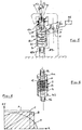
- Each connecting element 2 may comprise, depending on the needs of the cause, either an omnidirectional conformation 2a as shown in FIG. 7, or a directional conformation 2b as shown in FIG. 8.
- An omnidirectional connecting element 2a comprises in the first place, two pedicle screws 3a-3b fixed on each of the vertebrae 4a (high) and 4b (low) and their protruding threaded part receives anchoring means 5-6 consisting of two half -clamps 5a-5b and 6a-6b tightened by nuts 7 and 8.
- the element is completed by an omnidirectional connecting device 9 having tails 9a-9b which can be twisted by conventional surgical tools at the time of installation, to come to fit very exactly between the half collars of the anchoring means 5 and 6.
- the assembly thus formed is blocked by the nuts 7-8 after installation taking into account the adjustment and the intervertebral positioning e1.
- connection device 9 does not have a preferred angular orientation as appears from the examination of FIG. 6.
- the connecting device 9 has tails 9a-9b and has a hollow oblong body of revolution 10 such as cylindrical, split helically to make it elastic axially and section 11 has a closed shape preferably rectangular while at the upper and lower parts are fixed said tails 9a-9b and the hollow central part 12 of said body is filled at rest with a viscoelastic damping product flowed in interfering overflow.
- a directional connecting element 2b also comprises, first of all, two pedicle screws 14a-14b fixed on each of the vertebrae 15a (High) and 15b (low) and their protruding threaded part, receives anchoring means 16-17 made up of half-collars 16a-16b / 17a-17b tightened by nuts 24-25.
- the body 20 of the connecting device 18 which may be cylindrical, comprises asymmetrical transverse slots 21 lined at rest with a viscoelastic product 22 creeping into interfering overflow.
- Such an element 2b is said to be directional in the sense that the number, the width, the depth and the angular orientations of the slots 21 makes it possible, by suitable positioning "0", to elastically correct certain defects such as scoliosis for example.
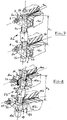
- FIG. 5 shows how the connection devices 2a or 2b can be tested in fatigue after embedding their tails 9a-9b or 18a-18b in the jaws of a test bench marked diagrammatically 23 in this figure and whose mechanical elements are easily conceivable.
- the tests are carried out by controlling the positioning of the point v relative to the ellipsoid E as well as the orientation "0" and all the information is collected by a sensor 24 and processed by a measurement chain 25.
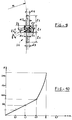
- Figure 9 shows the dimensional characteristics of the device used and Figure 10 the test results obtained in the form of a graphic recording.
- a pre-wiring of R 220 mm. can be used to facilitate installation.
- FIG. 10 shows the curve resulting from the test carried out on the assembly dimensioned above and made up of a mirror-polished biocompatible ISO 5832/3 steel.
- Figures 11 and 12 show, by way of example of an embodiment, two front and profile radiographs of the recent implantation carried out by one of the applicants who is Doctor ELBERG, of a spinal prosthetic assembly conforming to the invention (26) on a patient aged 60 years.
Abstract
Description
L'invention concerne les prothèses pouvant être appliquées sur la totalité des vertèbres du rachis.The invention relates to prostheses which can be applied to all the vertebrae of the spine.
Un rachis normal peut être considéré en bonne approximation à la fois comme un système élastique ou chaque liaison intervertébrale reprend sa position d'origine dès que l'effort appliqué a cessé et qui est associé à un système avec amortissement dans la mesure ou l'ènergie résultant des chocs divers est dissipée sous forme de chaleur et n'est pas restitué au système élastique sous forme mécanique.A normal spine can be considered as a good approximation both as an elastic system or each intervertebral connection returns to its original position as soon as the applied force has ceased and which is associated with a system with damping as far as energy resulting from various shocks is dissipated in the form of heat and is not returned to the elastic system in mechanical form.
Les contraintes appliquées sur un rachis normal peuvent être trés importantes et l'on estime par exemple, que la vertébre L3 supportant une charge normale de 70 daN, peut subir une surcharge de 120 daN pour un sujet penché à 20° et 340 daN en soulevant seulement un poids de 20 Kg jambes tendues.The stresses applied on a normal spine can be very important and it is estimated for example, that the L3 vertebra supporting a normal load of 70 daN, can undergo an overload of 120 daN for a subject leaning at 20 ° and 340 daN while lifting only a weight of 20 Kg stretched legs.
On sait d'autre part que ce même rachis peut enregistrer jusqu'à 2 millions en moyenne de sollicitations et chocs de diffèrentes natures par années soit une centaine de millions de cycles de contraintes durant la vie active moyenne d'un individu. Toutes les prothèses rachidiennes doivent donc répondre idéalement à plusieurs objectifs aussi proches que possible des conditions rencontrées "in vivo" en particulier: d'élasticité, d'amortissement et de tenue en fatigue.We know on the other hand that this same spine can record up to 2 million on average of stresses and shocks of different natures per year, that is to say a hundred million cycles of stresses during the average active life of an individual. All spinal prostheses must therefore ideally meet several objectives as close as possible to the conditions encountered "in vivo" in particular: elasticity, damping and fatigue resistance.
Ces domaines ont été trés recherchés et l'on trouve une abondante littérature sur ce sujet ainsi que divers brevets.These fields have been much sought after and there is an abundant literature on this subject as well as various patents.
Parmi la littérature on peut citer:Three-dimensional biomechanical properties of the human cervical spine in vitro(European spine journal 1993),
- A biomechanical analysis of short segment spinal fixation using a tree-domensional geometric and mechanical model (spine vol.18
number 5. P.P 536-545 -1993), - Three dimensional geometrical and mechanical modeling of the lumbar spine (biomechanical vol. 25 N° 10 P.P 1164/1992),
Influence of geometrical factors on the behavior of lumbar spine segments: a finite element analysis (Europeean spine journal -1994), - comportement bio-mécanique d'un ressort inter-apophysaire vertébral postérieur. Analyse expérimentale du comportement discal en compression. (rachis 1993- Vol 5 N°2)
- A biomechanical analysis of short segment spinal fixation using a tree-domensional geometric and mechanical model (spine vol.18
number 5. PP 536-545 -1993), - Three dimensional geometrical and mechanical modeling of the lumbar spine (biomechanical vol. 25 N ° 10 PP 1164/1992),
Influence of geometrical factors on the behavior of lumbar spine segments: a finite element analysis (Europeean spine journal -1994), - bio-mechanical behavior of a posterior vertebral inter-apophyseal spring. Experimental analysis of disc behavior in compression. (spine 1993- Vol 5 N ° 2)
Parmi les brevets, on peut citer:
- le N°F 2681525 qui concerne un amortisseur seul interépineux,
- le N°F 2683445 qui présente un autre type d'amortisseur seul à plaques.
- le N°EP 516567 qui dispose un amortisseur seul avec tête rotulante,
- le N°EP 576379 qui décrit un amortisseur seul avec limites de débattements axiaux,
- le N° EP 538183 qui montre une pastille intervertébrale souple mise en place par griffes en lieu et place du nucléus pulposus.
- N ° F 2681525 which concerns a single interspinous shock absorber,
- N ° F 2683445 which presents another type of shock absorber alone with plates.
- N ° EP 516567 which has a single shock absorber with swiveling head,
- No. EP 576379 which describes a shock absorber alone with axial travel limits,
- No. EP 538183 which shows a flexible intervertebral pellet placed by claws in place of the pulposus nucleus.
Toutes ces études et brevets ne visent que des fonctions dissociées soit d'amortissement soit d'élasticité et n'entrent pas de ce fait dans le champ d'application de l'invention.All of these studies and patents only target dissociated functions, either damping or elasticity, and therefore do not fall within the scope of the invention.
De plus, l'invention vise un procédé permettant de paramètrer les éléments spécifiques d'une prothèse intervertébrale consistant à déterminer par tous moyens appropriés tels que radiographie,scanner,imagerie RM, les défauts à corriger en rapport avec l'anomalie constatée, à analyser ces défauts, à modéliser la prothèse, à la soumettre aprés modélisation à des essais de fatigue sur un banc de fatigue spécialisé, puis aprés caractérisation,à procéder à son implantation sur le patient.In addition, the invention relates to a method making it possible to configure the specific elements of an intervertebral prosthesis consisting in determining by any appropriate means such as radiography, scanner, MR imaging, the defects to be corrected in relation to the anomaly observed, to be analyzed. these defects, to model the prosthesis, to submit it after modeling to fatigue tests on a specialized fatigue bench, then after characterization, to proceed to its implantation on the patient.
l'invention permet en outre, par un dispositif de liaison intervertébrale approprié, associé à des moyens d'ancrage sur les vertébres, d'orienter l'action du moyen élastique et d'amortissement dudit dispositif de liaison de telle sorte que le praticien puisse corriger certaines affections telles que scolioses par exemple.the invention also makes it possible, by an appropriate intervertebral connection device, associated with anchoring means on the vertebrae, to orient the action of the elastic means and of damping of said connection device so that the practitioner can correct certain ailments such as scoliosis for example.
D'une manière générale, toutes les liaisons interpédiculaires consistent pour le praticien:
- à fixer les vis pédiculaires sur les deux vertébres adjacentes intéréssées,
- à utiliser la partie dépassante de ces vis pour assujettir des moyens d'ancrage avec leur système de blocage adapté,
- à relier au moins deux moyens d'ancrage adjacents par un dispositif de liaison omnidirectionnel ou directionnel qui aprés blocage, réalise l'immobilisation recherchée,
sans perdre de vue le fait que le geste opératoire doit être aidé par la facilité de pose des divers constituants.
- to fix the pedicle screws on the two adjacent vertebrae,
- to use the projecting part of these screws to secure anchoring means with their suitable blocking system,
- to connect at least two adjacent anchoring means by an omnidirectional or directional connection device which, after blocking, achieves the immobilization sought,
without losing sight of the fact that the operative gesture must be helped by the ease of installation of the various constituents.
L'invention, exposée ci-aprés à l'aide des dessins annexés,comprend deux parties afin d'en assurer une meilleure compréhension:
- . d'une part, l'explication théorique mettant en évidence l'apparition de la nécessité de mettre en oeuvre une prothèse intervertébrale,
- . d'autre part, la description du fonctionnement de la prothèse selon l'invention s'insèrant dans un ensemble rachidien et comportant au moins un élément intervertébral incluant sur deux vis pédiculaires, deux moyens d'ancrage recevant un dispositif de liaison élastique avec amortissement qui peut être omnidirectionnel ou directionnel et avoir été modélisé avant implantation.
- . on the one hand, the theoretical explanation highlighting the appearance of the need to use an intervertebral prosthesis,
- . on the other hand, the description of the operation of the prosthesis according to the invention fitting into a spinal assembly and comprising at least one intervertebral element including on two pedicle screws, two anchoring means receiving an elastic connection device with damping which can be omnidirectional or directional and have been modeled before implantation.
Sur les dessins:
- la figure 1 est une représentation schèmatique montrant à titre d'exemple, le positionnement de prothèses selon l'invention sur un segment rachidien entre les vertèbres L5 à L1 et D12 et vu en coupe partielle unilatèrale,
- la figure 2 est une vue trés schèmatique montrant le comportement mécanique possible des deux vertèbres L5-L4 les plus chargées et prises comme référence,
- les figures 3 et 4 sont des graphiques montrant respectivement les contraintes en fatigue pouvant être appliquées sur le rachis et le mode de travail type d'un ressort;
agissant conjointement ou non avec un amortisseur, - les figures 5 et 6 représentent en perspective, d'une part,un dispositif de liaison directionnel avec représenté symboliquement un banc d'essais en fatigue et,d'autre part, un dispositif de liaison onmidirectionnel; cesdits dispositifs étant conformes à l'invention,
- les figures 7 et 8 montrent respectivement en perspective, un élément de liaison omnidirectionnel et un élément de liaison directionnel selon l'invention.
- La figure 9 montre un ensemble réel testé et la fig.10 les résultats de l'essais.
- Les figures 11 et 12 représentent des radiographies aprés pose.
- FIG. 1 is a schematic representation showing by way of example, the positioning of prostheses according to the invention on a spinal segment between the vertebrae L5 to L1 and D12 and seen in unilateral partial section,
- FIG. 2 is a very schematic view showing the possible mechanical behavior of the two most loaded L5-L4 vertebrae taken as a reference,
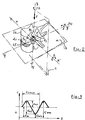
- Figures 3 and 4 are graphs respectively showing the fatigue stresses that can be applied to the spine and the typical working mode of a spring;
acting jointly or not with a shock absorber, - Figures 5 and 6 show in perspective, on the one hand, a directional connection device with symbolically represented a test bench in fatigue and, on the other hand, an onmidirectional connection device; these said devices being in accordance with the invention,
- Figures 7 and 8 show respectively in perspective, an omnidirectional connecting element and a directional connecting element according to the invention.
- Figure 9 shows a real set tested and fig.10 the results of the tests.
- Figures 11 and 12 show post-exposure radiographs.
Si l'on se reporte à la figure 1, on voit représenté partiellement à titre d'exemple sur un rachis et entre les vertèbres L5 et D12, des éléments de liaison intervertébraux selon l'invention avec leurs vis pédiculaires, leurs moyens d'ancrage et leurs propres dispositifs de liaison.If we refer to Figure 1, we see shown partially by way of example on a spine and between the vertebrae L5 and D12, intervertebral connecting elements according to the invention with their pedicle screws, their anchoring means and their own connecting devices.
Ces éléments de liaison repérés 2 constituent un ensemble de liaison repéré 1 et peuvent, dans le sens de l'invention, être indiffèremment conformés selon les figures 7 ou 8 comme cela sera explicité dans la suite du texte.These connection elements identified 2 constitute a connection assembly identified 1 and can, in the sense of the invention, be indifferently shaped according to Figures 7 or 8 as will be explained in the following text.
Ils peuvent en outre conformèment à l'usage, être disposés de part et d'autre de l'épine dorsale bien que la plupart des dessins ne représentent que l'un de ces côtés.Comme représenté schèmatiquement sur la figure 2 on montre les charges et contraintes mécaniques que peuvent subir in vivo les vertébres L5-L4 prises comme référence.They can furthermore, in accordance with usage, be arranged on either side of the backbone although most of the drawings represent only one of these sides. As shown diagrammatically in FIG. 2, the loads are shown. and mechanical stresses that L5-L4 vertebrae can undergo in vivo, taken as a reference.
Ces vertèbres comportent un disque d'interposition di, composé du nucléus pulposus entouré de l'anulus qui est une substance fibreuse, et les points d'appui sont représentés en p2-p3 par les apophyses articulaires et en p1 par le centre de pression appliqué sur la partie centrale du nucléus pulposus.These vertebrae have an interposition disc di, composed of the pulposus nucleus surrounded by the anulus which is a fibrous substance, and the support points are represented in p2-p3 by the articular processes and in p1 by the center of pressure applied on the central part of the pulposus nucleus.
A l'intérieur de ces points d'appuis, se trouve situé un point virtuel v d'application de la force instantannée de compression F et pouvant s'inscrire dans un ellipsoïde E normalement contenu dans ce triangle p1-p2-p3,mais pouvant s'en écarter par suite d'une déficience mécanique desdits points d'appuis.Inside these support points, there is a virtual point v of application of the instantaneous compression force F and which can be inscribed in an ellipsoid E normally contained in this triangle p1-p2-p3, but which can deviate from it due to a mechanical deficiency of said support points.
A l'état fondamental normal,le triangle p1-p2-p3 définit les plans d'assiette x-x'/y-y' horizontalement et z-z' verticalement.In the normal ground state, the triangle p1-p2-p3 defines the attitude planes x-x '/ y-y' horizontally and z-z 'vertically.
Considérant que le rachis peut assumer normalement des débattements tels que:
on admet qu'un dépassement significatif de ces valeurs moyennes représentée symboliquement par les variations représentées par a et/ou b, et/ou c, sur la figure 2, peut entraîner des déformations importantes relevables d'une intervention éventuelle de pose d'une prothèse.Considering that the spine can normally assume deflections such as:
it is admitted that a significant overshoot of these average values symbolically represented by the variations represented by a and / or b, and / or c, in FIG. 2, can cause significant deformations which can be noted as a result of a possible installation of a prosthesis.
Se superposent par ailleurs à ces déformations, des contraintes cycliques comme cela a déja été mentionné.In addition, these deformations are superimposed, cyclical constraints as already mentioned.
La figure 3 montre à cet effet en référence aux symboles usités en résistance des matériaux, les contraintes pouvant s'exercer selon X-Y-Z autour des axes principaux.FIG. 3 shows for this purpose with reference to the symbols used in resistance of materials, the constraints that can be exerted along X-Y-Z around the main axes.
Ces symboles sont notés:
- . σ max. -contrainte maximale qui est la plus grande valeur algébrique au cours d'un cycle de contrainte (traction ou tension +,compression ou pression -),
- . σ min. -contrainte minimale qui est la plus petite valeur algébrique au cours d'un cycle de contrainte,
- . σ m -contrainte moyenne qui est la composante statique de la contrainte et la moyenne algébrique des contraintes σ max et σ min,
- . σ a1.2 -amplitude de la contrainte qui est la composante alternée de la contrainte, demi différence algébrique entre σ max et σ min,
- . f -fréquences de cycles (min. sec.)
Résistance à la fatigue (d'aprés ISO R 373- 1964)
- . N -endurance ou longévité à la fatigue correspondant au nombre de cycles nécessaires pour provoquer la rupture (généralement exprimée en multiples de 10⁶)
- . σ n -résistance à la fatigue pour N cycles ou valeur de la sollicitation pour laquelle le dispositif présenterait une longévité de N cycles.
- . σ D -limite de fatigue, déterminée statistiquement et qui peut être illimitée,
- . δ - contrainte de cisaillement.
- . σ max. -maximum stress which is the greatest algebraic value during a stress cycle (traction or tension +, compression or pressure -),
- . σ min. -minimum stress which is the smallest algebraic value during a stress cycle,
- . σ m - mean stress which is the static component of the stress and the algebraic mean of the stresses σ max and σ min,
- . σ a 1.2 - amplitude of the stress which is the alternating component of the stress, half algebraic difference between σ max and σ min,
- . f -frequencies of cycles (min. sec.)
Fatigue resistance (according to ISO R 373- 1964)
- . N - fatigue endurance or longevity corresponding to the number of cycles necessary to cause rupture (generally expressed in multiples of 10⁶)
- . σ n -resistance to fatigue for N cycles or value of the stress for which the device would have a longevity of N cycles.
- . σ D - fatigue limit, statistically determined and which can be unlimited,
- . δ - shear stress.
On a reporté sur la figure 2 symboliquement, les contraintes exercées et représentées sur la figure 3.The stresses exerted and shown in FIG. 3 are reported symbolically in FIG. 2.
La partie descriptive donnée à titre de forme de réalisation, va montrer comment l'invention peut être mise en oeuvre à travers la suite du texte.The descriptive part given as an embodiment will show how the invention can be implemented through the rest of the text.
En se reportant à la figure 1, on rappelle qu'un ensemble prothètique rachidien selon l'invention, repéré 1 dans son ensemble, comporte en nombre convenable des éléments prothétiques de liaison 2 disposés généralement de part et d'autre de l'épine dorsale.Referring to FIG. 1, it should be recalled that a spinal prosthetic assembly according to the invention, identified 1 as a whole, comprises in suitable number of
Dans l'exemple, l'ensemble 1 englobe les vertébres L5 à D12.In the example, the
Chaque élément de liaison 2 peut comporter, selon les besoins de la cause, une conformation soit omnidirectionnelle 2a comme représenté sur la figure 7,soit directionnelle 2b comme représenté sur la figure 8.Each connecting
Un élément de liaison omnidirectionnel 2a, comprend en premier lieu, deux vis pédiculaires 3a-3b assujetties sur chacune des vertébres 4a (haute) et 4b (basse) et leur partie dépassante filetée reçoit des moyens d'ancrage 5-6 constitués de deux demi-colliers 5a-5b et 6a-6b serrés par des écrous 7 et 8.An omnidirectional connecting element 2a, comprises in the first place, two pedicle screws 3a-3b fixed on each of the
L'élément est complété par un dispositif de liaison 9 omnidirectionnel possèdant des queues 9a-9b pouvant être tordues par des outils chirurgicaux classiques au moment de la pose, pour venir s'adapter trés exactement entre les demi colliers des moyens d'ancrage 5 et 6.The element is completed by an omnidirectional connecting
l'ensemble ainsi constitué est bloqué par les écrous 7-8 aprés mise en place en tenant compte du réglage et du positionnement intervertébral e1.the assembly thus formed is blocked by the nuts 7-8 after installation taking into account the adjustment and the intervertebral positioning e1.
Un tel élément 2a est dit omnidirectionnel en ce sens que le dispositif de liaison 9 n'a pas d'orientation angulaire privilégiée comme cela ressort de l'examen de la figure 6.Such an element 2a is said to be omnidirectional in the sense that the
Sur cette figure 6 on voit que le dispositif de liaison 9 comporte des queues 9a-9b et présente un corps de révolution oblong creux 10 tel que cylindrique,fendu hélicoidalement afin de le rendre élastique axialement et la section 11 présente une allure fermée de préférence rectangulaire tandis qu'aux parties supérieures et inférieures sont fixées lesdites queues 9a-9b et que la partie centrale creuse 12 dudit corps est remplie au repos d'un produit viscoélastique d'amortissement flué en débordement interfente.In this figure 6 we see that the connecting
Un élément de liaison directionnel 2b comprend également, en premier lieu,deux vis pédiculaires 14a-14b assujetties sur chacune des vertèbres 15a (Haute) et 15b (basse) et leur partie dépassante filetée, reçoit des moyens d'ancrage 16-17 constitués de demi-colliers 16a-16b/17a-17b serrés par des écrous 24-25.A directional connecting
Ces demi-colliers ont une empreinte sphérique afin d'enserrer des noix cylindro-sphériques 22-23 avec fentes 26-27 recevant les queues 18a-18b du dispositif de liaison 18 et les écrous 24-25 assurent par serrage et aprés réglage de l'espace intervertébral e2 et le positionnement angulaire correct selon "0", le blocage de l'ensemble.These half-collars have a spherical imprint in order to enclose cylindro-spherical nuts 22-23 with slots 26-27 receiving the
le corps 20 du dispositif de liaison 18 qui peut être cylindrique, comporte des fentes transversales dissymétriques 21 garnies au repos d'un produit viscoélastique 22 flué en débordement interfentes.the
Un tel élément 2b est dit directionnel en ce sens que le nombre, la largeur,la profondeur et les orientations angulaires des fentes 21 permet par un positionnement convenable "0", de corriger élastiquement certains défauts tels que scolioses par exemple.Such an
La figure 5 montre comment les dispositifs de liaison 2a ou 2b peuvent être testés en fatigue aprés encastrement de leurs queues 9a-9b ou 18a-18b dans les mors d'un banc d'essais repéré schèmatiquement 23 sur cette figure et dont les éléments mécaniques sont aisèment concevables.FIG. 5 shows how the
Un tel banc permet d'afficher pratiquement tous les paramètres utiles à la définition des dispositifs de liaison selon l'invention.Such a bench makes it possible to display practically all the parameters useful for the definition of the connection devices according to the invention.
Ainsi on peut définir à titre d'exemple :
- la force d'application axiale F estimée à 100 daN,
- la flexion latérale sens x-x' :
α 1=4°-α 2=4° - la flexion latérale sens y-y' : β 1=4°-
β 2=4° - la rotation autour de l'axe z-z' : γ 1=1°-
γ 2=1°
pour un nombre de cycles dépassant 10⁶.So we can define as an example:
- the axial application force F estimated at 100 daN,
- lateral bending direction xx ':
α 1 = 4 ° -α 2 = 4 ° - lateral bending in yy 'direction:
β 1 = 4 ° -β 2 = 4 ° - the rotation around the zz 'axis: γ 1 = 1 ° -
γ 2 = 1 °
for a number of cycles exceeding 10⁶.
les essais sont conduits en contrôlant le positionnement du point v par rapport à l'ellipsoide E ainsi que l'orientation "0" et toutes les informations sont recueillies parun capteur 24 et traitées par une chaîne de mesures 25.the tests are carried out by controlling the positioning of the point v relative to the ellipsoid E as well as the orientation "0" and all the information is collected by a
Les demandeurs ont conduit sur banc d'essais adapté, des essais permettant de définir un ensemble rachidien prothétique biomécanique proche de celui existant in-vivo.The applicants conducted tests on an adapted test bench, allowing the definition of a biomechanical prosthetic spinal assembly close to that existing in vivo.
La figure 9 montre les caractéristiques dimensionnelles du disposifif mis en oeuvre et la figure 10 les résultats d'essais obtenus sous forme d'un enregistrement graphique.Figure 9 shows the dimensional characteristics of the device used and Figure 10 the test results obtained in the form of a graphic recording.
Selon cette figure 9, ledit dispositif prothétique présente les caractéristiques dimensionnelles suivantes (en mm.): d1 (ext)= 13/ d2 (int)= 7/ d3=d4= 6/ℓ1 =12/ℓ2= 3= 18/ℓ 4=ℓ5= 1,5/ s1= 4/ s2= 2,5/ f= 2,5 /ℓ 6=ℓ7= 3,8 et les disques d'extrémités d'ep 1,5 ont été soudés par faisceaux d'électrons sur les queues qui par ailleurs présentent des pointes de diamant en surface pour empêcher la rotation axiale aprés fixation.According to this figure 9, said prosthetic device has the following dimensional characteristics (in mm.): D1 (ext) = 13 / d2 (int) = 7 / d3 = d4 = 6 / ℓ1 = 12 / ℓ2 = 3 = 18 / ℓ 4 = ℓ5 = 1.5 / s1 = 4 / s2 = 2.5 / f = 2.5 / ℓ 6 = ℓ7 = 3.8 and the end discs of ep 1.5 were welded by bundles d electrons on the tails which also have diamond tips on the surface to prevent axial rotation after fixing.
Un précambrage de R=220 mm. peut être pratiqué pour faciliter la pose.A pre-wiring of R = 220 mm. can be used to facilitate installation.
La figure 10 montre la courbe résultante de l'essais pratiqué sur l'ensemble dimensionné ci-dessus et constitué d'un acier 5832/3 ISO biocompatible poli miroir.FIG. 10 shows the curve resulting from the test carried out on the assembly dimensioned above and made up of a mirror-polished biocompatible ISO 5832/3 steel.
Sur cette figure, on note les points caractéristiques suivants:
Ces points caractéristiques sont trés proches de ceux résultant du comportement biomécanique humain selon les conceptions généralement admises.These characteristic points are very close to those resulting from human biomechanical behavior according to generally accepted conceptions.
Les figures 11 et 12 représentent, à titre d'exemple de réalisation, deux radiographies de face et de profil de l'implantation récente effectuée par l'un des demandeurs qui est le Docteur ELBERG, d'un ensemble prothétique rachidien conforme à l'invention (26) sur un patient agé de 60 ans.Figures 11 and 12 show, by way of example of an embodiment, two front and profile radiographs of the recent implantation carried out by one of the applicants who is Doctor ELBERG, of a spinal prosthetic assembly conforming to the invention (26) on a patient aged 60 years.
Claims (10)
Applications Claiming Priority (6)
| Application Number | Priority Date | Filing Date | Title |
|---|---|---|---|
| FR9403189 | 1994-03-18 | ||
| FR9403189A FR2717370A1 (en) | 1994-03-18 | 1994-03-18 | Intervertebral stabilising prosthesis for spinal reinforcement inserted during spinal surgery |
| FR9415049 | 1994-12-14 | ||
| FR9415049A FR2728158A1 (en) | 1994-12-14 | 1994-12-14 | Spinal column prosthesis |
| FR9501561 | 1995-02-10 | ||
| FR9501561A FR2730405A1 (en) | 1995-02-10 | 1995-02-10 | Spinal column prosthesis |
Publications (2)
| Publication Number | Publication Date |
|---|---|
| EP0677277A2 true EP0677277A2 (en) | 1995-10-18 |
| EP0677277A3 EP0677277A3 (en) | 1996-02-28 |
Family
ID=27252885
Family Applications (1)
| Application Number | Title | Priority Date | Filing Date |
|---|---|---|---|
| EP95400558A Withdrawn EP0677277A3 (en) | 1994-03-18 | 1995-03-15 | Spinal prosthetic assembly. |
Country Status (1)
| Country | Link |
|---|---|
| EP (1) | EP0677277A3 (en) |
Cited By (111)
| Publication number | Priority date | Publication date | Assignee | Title |
|---|---|---|---|---|
| WO1997035529A1 (en) * | 1996-03-27 | 1997-10-02 | Rehak Lubos | The device for the correction of spinal deformities |
| FR2751201A1 (en) * | 1996-07-22 | 1998-01-23 | Zacouto Fred | Osteosynthesis implant |
| FR2751202A1 (en) * | 1996-07-22 | 1998-01-23 | Zacouto Fred | SKELETAL IMPLANT |
| FR2771280A1 (en) * | 1997-11-26 | 1999-05-28 | Albert P Alby | RESILIENT VERTEBRAL CONNECTION DEVICE |
| FR2774581A1 (en) * | 1998-02-10 | 1999-08-13 | Dimso Sa | INTEREPINOUS STABILIZER TO BE ATTACHED TO SPINOUS APOPHYSIS OF TWO VERTEBRES |
| DE10004712C1 (en) * | 2000-02-03 | 2001-08-09 | Aesculap Ag & Co Kg | Bone plate for bone fracture or fixing adjacent vertebrae has intermediate section between plate-shaped regions secured to fracture sections or vertebrae provided with transverse slits |
| FR2814936A1 (en) * | 2000-10-11 | 2002-04-12 | Frederic Fortin | Supple one-piece vertebral connector has central core with elastic fibres, fixings and polymerised resin covering |
| US6419677B2 (en) | 1997-01-02 | 2002-07-16 | St. Francis Medical Technologies, Inc. | Spine distraction implant and method |
| US6514256B2 (en) | 1997-01-02 | 2003-02-04 | St. Francis Medical Technologies, Inc. | Spine distraction implant and method |
| US6582433B2 (en) | 2001-04-09 | 2003-06-24 | St. Francis Medical Technologies, Inc. | Spine fixation device and method |
| US6652534B2 (en) | 1998-10-20 | 2003-11-25 | St. Francis Medical Technologies, Inc. | Apparatus and method for determining implant size |
| US6652527B2 (en) | 1998-10-20 | 2003-11-25 | St. Francis Medical Technologies, Inc. | Supplemental spine fixation device and method |
| EP1281364A3 (en) * | 2001-08-01 | 2004-01-07 | Showa IKA Kohgyo Co., Ltd. | Bone connector |
| US6695842B2 (en) | 1997-10-27 | 2004-02-24 | St. Francis Medical Technologies, Inc. | Interspinous process distraction system and method with positionable wing and method |
| US6699246B2 (en) | 1997-01-02 | 2004-03-02 | St. Francis Medical Technologies, Inc. | Spine distraction implant |
| US6699247B2 (en) | 1997-01-02 | 2004-03-02 | St. Francis Medical Technologies, Inc. | Spine distraction implant |
| FR2844180A1 (en) * | 2002-09-11 | 2004-03-12 | Spinevision | Connection element for spinal fixation system designed to link at least two implantable connection assemblies, is formed from a helicoidal spring part and a polymeric material support part |
| US6712819B2 (en) | 1998-10-20 | 2004-03-30 | St. Francis Medical Technologies, Inc. | Mating insertion instruments for spinal implants and methods of use |
| US6796983B1 (en) | 1997-01-02 | 2004-09-28 | St. Francis Medical Technologies, Inc. | Spine distraction implant and method |
| US6835207B2 (en) | 1996-07-22 | 2004-12-28 | Fred Zacouto | Skeletal implant |
| WO2005044117A2 (en) * | 2003-11-07 | 2005-05-19 | Biedermann Motech Gmbh | Spring element for a bone stabilizing device, and method for the production of said spring element |
| US6986771B2 (en) | 2003-05-23 | 2006-01-17 | Globus Medical, Inc. | Spine stabilization system |
| EP1628563A2 (en) * | 2003-05-23 | 2006-03-01 | Globus Medical, Inc. | Spine stabilization system |
| EP1658815A1 (en) * | 2004-11-17 | 2006-05-24 | BIEDERMANN MOTECH GmbH | Elastic element for use in a stabilising device for bones or vertebrae |
| WO2006066053A1 (en) * | 2004-12-15 | 2006-06-22 | Stryker Spine | Spinal rods having segments of different elastic properties and methods of using them |
| WO2006074191A2 (en) * | 2005-01-04 | 2006-07-13 | Warsaw Orthopedic, Inc. | Systems and methods for spinal stabilization with flexible elements |
| JP2007508085A (en) * | 2003-10-17 | 2007-04-05 | ヴィーダーマン モテッヒ ゲーエムベーハー | Flexible implant |
| EP1779814A1 (en) * | 2005-10-26 | 2007-05-02 | BIEDERMANN MOTECH GmbH | Implant having a single piece swivel joint |
| FR2892616A1 (en) * | 2005-11-02 | 2007-05-04 | Spinevision Sa | Surgical implant for assisting relative movement of vertebrae, has viscoelastic element that absorbs energy of shocks between two vertebrae, and parts with respective anchoring units permitting fixation of element on portions of parts |
| EP1827265A2 (en) * | 2003-09-24 | 2007-09-05 | N Spine, Inc. | Spinal stabilization device |
| WO2008115280A2 (en) * | 2006-10-30 | 2008-09-25 | Warsaw Orthopedic, Inc. | Vertebral rods and methods of use |
| US7550010B2 (en) | 2004-01-09 | 2009-06-23 | Warsaw Orthopedic, Inc. | Spinal arthroplasty device and method |
| US7556651B2 (en) | 2004-01-09 | 2009-07-07 | Warsaw Orthopedic, Inc. | Posterior spinal device and method |
| US7597694B2 (en) | 2004-01-30 | 2009-10-06 | Warsaw Orthopedic, Inc. | Instruments and methods for minimally invasive spinal stabilization |
| US7621912B2 (en) | 2003-10-17 | 2009-11-24 | Biedermann Motech Gmbh | Rod-shaped implant element with flexible section |
| US7695513B2 (en) | 2003-05-22 | 2010-04-13 | Kyphon Sarl | Distractible interspinous process implant and method of implantation |
| WO2010019857A3 (en) * | 2008-08-14 | 2010-04-15 | Synthes Usa, Llc | Posterior dynamic stabilization system |
| US7722649B2 (en) | 2002-08-09 | 2010-05-25 | Biedermann Motech Gmbh | Dynamic stabilization device for bones, in particular for vertebrae |
| US7749252B2 (en) | 2005-03-21 | 2010-07-06 | Kyphon Sarl | Interspinous process implant having deployable wing and method of implantation |
| US7763050B2 (en) | 2004-12-13 | 2010-07-27 | Warsaw Orthopedic, Inc. | Inter-cervical facet implant with locking screw and method |
| US7771479B2 (en) | 2004-01-09 | 2010-08-10 | Warsaw Orthopedic, Inc. | Dual articulating spinal device and method |
| US7776090B2 (en) | 2004-12-13 | 2010-08-17 | Warsaw Orthopedic, Inc. | Inter-cervical facet implant and method |
| US7803190B2 (en) | 2002-10-29 | 2010-09-28 | Kyphon SÀRL | Interspinous process apparatus and method with a selectably expandable spacer |
| US7811326B2 (en) | 2006-01-30 | 2010-10-12 | Warsaw Orthopedic Inc. | Posterior joint replacement device |
| US7833246B2 (en) | 2002-10-29 | 2010-11-16 | Kyphon SÀRL | Interspinous process and sacrum implant and method |
| US7875077B2 (en) | 2004-01-09 | 2011-01-25 | Warsaw Orthopedic, Inc. | Support structure device and method |
| US7901459B2 (en) | 2004-01-09 | 2011-03-08 | Warsaw Orthopedic, Inc. | Split spinal device and method |
| US7909853B2 (en) | 2004-09-23 | 2011-03-22 | Kyphon Sarl | Interspinous process implant including a binder and method of implantation |
| WO2011055396A1 (en) * | 2009-11-09 | 2011-05-12 | Sintea Plustek S.R.L. | Modular element for dynamic spinal vertebra stabilization systems |
| US7959652B2 (en) | 2005-04-18 | 2011-06-14 | Kyphon Sarl | Interspinous process implant having deployable wings and method of implantation |
| US8012209B2 (en) | 2004-09-23 | 2011-09-06 | Kyphon Sarl | Interspinous process implant including a binder, binder aligner and method of implantation |
| US8048117B2 (en) | 2003-05-22 | 2011-11-01 | Kyphon Sarl | Interspinous process implant and method of implantation |
| US8066739B2 (en) | 2004-02-27 | 2011-11-29 | Jackson Roger P | Tool system for dynamic spinal implants |
| US8070778B2 (en) | 2003-05-22 | 2011-12-06 | Kyphon Sarl | Interspinous process implant with slide-in distraction piece and method of implantation |
| US8075596B2 (en) | 2007-01-12 | 2011-12-13 | Warsaw Orthopedic, Inc. | Spinal prosthesis systems |
| US8100915B2 (en) | 2004-02-27 | 2012-01-24 | Jackson Roger P | Orthopedic implant rod reduction tool set and method |
| US8105368B2 (en) | 2005-09-30 | 2012-01-31 | Jackson Roger P | Dynamic stabilization connecting member with slitted core and outer sleeve |
| EP1562500B1 (en) * | 2002-08-13 | 2012-03-28 | Siguler Guff Distressed Opportunities Fund III, LP | Distraction and damping system which can be adjusted as the vertebral column grows |
| US8252028B2 (en) | 2007-12-19 | 2012-08-28 | Depuy Spine, Inc. | Posterior dynamic stabilization device |
| US8273089B2 (en) | 2004-11-23 | 2012-09-25 | Jackson Roger P | Spinal fixation tool set and method |
| US8353932B2 (en) | 2005-09-30 | 2013-01-15 | Jackson Roger P | Polyaxial bone anchor assembly with one-piece closure, pressure insert and plastic elongate member |
| US8366745B2 (en) | 2007-05-01 | 2013-02-05 | Jackson Roger P | Dynamic stabilization assembly having pre-compressed spacers with differential displacements |
| US8394133B2 (en) | 2004-02-27 | 2013-03-12 | Roger P. Jackson | Dynamic fixation assemblies with inner core and outer coil-like member |
| US8425601B2 (en) | 2006-09-11 | 2013-04-23 | Warsaw Orthopedic, Inc. | Spinal stabilization devices and methods of use |
| US8475498B2 (en) | 2007-01-18 | 2013-07-02 | Roger P. Jackson | Dynamic stabilization connecting member with cord connection |
| US8506599B2 (en) | 2007-02-12 | 2013-08-13 | Roger P. Jackson | Dynamic stabilization assembly with frusto-conical connection |
| US8518084B2 (en) | 2006-01-24 | 2013-08-27 | Biedermann Technologies Gmbh & Co. Kg | Connecting rod with external flexible element |
| US8556938B2 (en) | 2009-06-15 | 2013-10-15 | Roger P. Jackson | Polyaxial bone anchor with non-pivotable retainer and pop-on shank, some with friction fit |
| US8623059B2 (en) | 2005-10-31 | 2014-01-07 | Stryker Spine | System and method for dynamic vertebral stabilization |
| US8632570B2 (en) | 2003-11-07 | 2014-01-21 | Biedermann Technologies Gmbh & Co. Kg | Stabilization device for bones comprising a spring element and manufacturing method for said spring element |
| CN103536345A (en) * | 2012-07-17 | 2014-01-29 | 上海微创骨科医疗科技有限公司 | Dynamic stabilization implanting unit for spine |
| US8771357B2 (en) | 2004-05-04 | 2014-07-08 | Biedermann Technologies Gmbh & Co. Kg | Flexible space holder |
| US8814913B2 (en) | 2002-09-06 | 2014-08-26 | Roger P Jackson | Helical guide and advancement flange with break-off extensions |
| US8858599B2 (en) | 2004-06-09 | 2014-10-14 | Warsaw Orthopedic, Inc. | Systems and methods for flexible spinal stabilization |
| US8864832B2 (en) | 2007-06-20 | 2014-10-21 | Hh Spinal Llc | Posterior total joint replacement |
| US8915964B2 (en) | 2008-07-14 | 2014-12-23 | DePuy Synthes Products, LLC | Flexible dampening intervertebral spacer device |
| US8920473B2 (en) | 2006-12-10 | 2014-12-30 | Paradigm Spine, Llc | Posterior functionally dynamic stabilization system |
| US9050148B2 (en) | 2004-02-27 | 2015-06-09 | Roger P. Jackson | Spinal fixation tool attachment structure |
| US9050139B2 (en) | 2004-02-27 | 2015-06-09 | Roger P. Jackson | Orthopedic implant rod reduction tool set and method |
| US9636146B2 (en) | 2012-01-10 | 2017-05-02 | Roger P. Jackson | Multi-start closures for open implants |
| US9668771B2 (en) | 2009-06-15 | 2017-06-06 | Roger P Jackson | Soft stabilization assemblies with off-set connector |
| USRE46431E1 (en) | 2003-06-18 | 2017-06-13 | Roger P Jackson | Polyaxial bone anchor with helical capture connection, insert and dual locking assembly |
| US9717533B2 (en) | 2013-12-12 | 2017-08-01 | Roger P. Jackson | Bone anchor closure pivot-splay control flange form guide and advancement structure |
| US9717534B2 (en) | 2009-06-15 | 2017-08-01 | Roger P. Jackson | Polyaxial bone anchor with pop-on shank and friction fit retainer with low profile edge lock |
| US9743957B2 (en) | 2004-11-10 | 2017-08-29 | Roger P. Jackson | Polyaxial bone screw with shank articulation pressure insert and method |
| US9770265B2 (en) | 2012-11-21 | 2017-09-26 | Roger P. Jackson | Splay control closure for open bone anchor |
| US9907574B2 (en) | 2008-08-01 | 2018-03-06 | Roger P. Jackson | Polyaxial bone anchors with pop-on shank, friction fit fully restrained retainer, insert and tool receiving features |
| US9918745B2 (en) | 2009-06-15 | 2018-03-20 | Roger P. Jackson | Polyaxial bone anchor with pop-on shank and winged insert with friction fit compressive collet |
| US9949762B2 (en) | 2005-02-22 | 2018-04-24 | Stryker European Holdings I, Llc | Apparatus and method for dynamic vertebral stabilization |
| US9980753B2 (en) | 2009-06-15 | 2018-05-29 | Roger P Jackson | pivotal anchor with snap-in-place insert having rotation blocking extensions |
| US10039578B2 (en) | 2003-12-16 | 2018-08-07 | DePuy Synthes Products, Inc. | Methods and devices for minimally invasive spinal fixation element placement |
| US10039577B2 (en) | 2004-11-23 | 2018-08-07 | Roger P Jackson | Bone anchor receiver with horizontal radiused tool attachment structures and parallel planar outer surfaces |
| US10058354B2 (en) | 2013-01-28 | 2018-08-28 | Roger P. Jackson | Pivotal bone anchor assembly with frictional shank head seating surfaces |
| US10064658B2 (en) | 2014-06-04 | 2018-09-04 | Roger P. Jackson | Polyaxial bone anchor with insert guides |
| US10194951B2 (en) | 2005-05-10 | 2019-02-05 | Roger P. Jackson | Polyaxial bone anchor with compound articulation and pop-on shank |
| US10258382B2 (en) | 2007-01-18 | 2019-04-16 | Roger P. Jackson | Rod-cord dynamic connection assemblies with slidable bone anchor attachment members along the cord |
| US10299839B2 (en) | 2003-12-16 | 2019-05-28 | Medos International Sárl | Percutaneous access devices and bone anchor assemblies |
| US10327818B2 (en) | 2012-06-18 | 2019-06-25 | Bruce Francis Hodgson | Method and apparatus for the treatment of scoliosis |
| US10349983B2 (en) | 2003-05-22 | 2019-07-16 | Alphatec Spine, Inc. | Pivotal bone anchor assembly with biased bushing for pre-lock friction fit |
| US10363070B2 (en) | 2009-06-15 | 2019-07-30 | Roger P. Jackson | Pivotal bone anchor assemblies with pressure inserts and snap on articulating retainers |
| USRE47551E1 (en) | 2005-02-22 | 2019-08-06 | Roger P. Jackson | Polyaxial bone screw with spherical capture, compression insert and alignment and retention structures |
| US10383660B2 (en) | 2007-05-01 | 2019-08-20 | Roger P. Jackson | Soft stabilization assemblies with pretensioned cords |
| US10729469B2 (en) | 2006-01-09 | 2020-08-04 | Roger P. Jackson | Flexible spinal stabilization assembly with spacer having off-axis core member |
| US10758274B1 (en) | 2014-05-02 | 2020-09-01 | Nuvasive, Inc. | Spinal fixation constructs and related methods |
| US10952777B2 (en) | 2003-04-09 | 2021-03-23 | Roger P. Jackson | Pivotal bone screw assembly with receiver having threaded open channel and lower opening |
| US11147591B2 (en) | 2004-11-10 | 2021-10-19 | Roger P Jackson | Pivotal bone anchor receiver assembly with threaded closure |
| US11229457B2 (en) | 2009-06-15 | 2022-01-25 | Roger P. Jackson | Pivotal bone anchor assembly with insert tool deployment |
| US11234745B2 (en) | 2005-07-14 | 2022-02-01 | Roger P. Jackson | Polyaxial bone screw assembly with partially spherical screw head and twist in place pressure insert |
| US11241261B2 (en) | 2005-09-30 | 2022-02-08 | Roger P Jackson | Apparatus and method for soft spinal stabilization using a tensionable cord and releasable end structure |
| US11419642B2 (en) | 2003-12-16 | 2022-08-23 | Medos International Sarl | Percutaneous access devices and bone anchor assemblies |
| US11890202B2 (en) | 2007-06-20 | 2024-02-06 | 3Spine, Inc. | Spinal osteotomy |
Families Citing this family (33)
| Publication number | Priority date | Publication date | Assignee | Title |
|---|---|---|---|---|
| FR2812185B1 (en) | 2000-07-25 | 2003-02-28 | Spine Next Sa | SEMI-RIGID CONNECTION PIECE FOR RACHIS STABILIZATION |
| US7862587B2 (en) | 2004-02-27 | 2011-01-04 | Jackson Roger P | Dynamic stabilization assemblies, tool set and method |
| US8292926B2 (en) | 2005-09-30 | 2012-10-23 | Jackson Roger P | Dynamic stabilization connecting member with elastic core and outer sleeve |
| US8876868B2 (en) | 2002-09-06 | 2014-11-04 | Roger P. Jackson | Helical guide and advancement flange with radially loaded lip |
| US8926670B2 (en) | 2003-06-18 | 2015-01-06 | Roger P. Jackson | Polyaxial bone screw assembly |
| US8092500B2 (en) | 2007-05-01 | 2012-01-10 | Jackson Roger P | Dynamic stabilization connecting member with floating core, compression spacer and over-mold |
| US8979900B2 (en) | 2003-09-24 | 2015-03-17 | DePuy Synthes Products, LLC | Spinal stabilization device |
| US7763052B2 (en) | 2003-12-05 | 2010-07-27 | N Spine, Inc. | Method and apparatus for flexible fixation of a spine |
| US7815665B2 (en) | 2003-09-24 | 2010-10-19 | N Spine, Inc. | Adjustable spinal stabilization system |
| US7137985B2 (en) | 2003-09-24 | 2006-11-21 | N Spine, Inc. | Marking and guidance method and system for flexible fixation of a spine |
| US7651502B2 (en) | 2004-09-24 | 2010-01-26 | Jackson Roger P | Spinal fixation tool set and method for rod reduction and fastener insertion |
| DE102004048938B4 (en) | 2004-10-07 | 2015-04-02 | Synthes Gmbh | Device for the dynamic stabilization of vertebral bodies |
| US8926672B2 (en) | 2004-11-10 | 2015-01-06 | Roger P. Jackson | Splay control closure for open bone anchor |
| US9216041B2 (en) | 2009-06-15 | 2015-12-22 | Roger P. Jackson | Spinal connecting members with tensioned cords and rigid sleeves for engaging compression inserts |
| US8444681B2 (en) | 2009-06-15 | 2013-05-21 | Roger P. Jackson | Polyaxial bone anchor with pop-on shank, friction fit retainer and winged insert |
| US9168069B2 (en) | 2009-06-15 | 2015-10-27 | Roger P. Jackson | Polyaxial bone anchor with pop-on shank and winged insert with lower skirt for engaging a friction fit retainer |
| US8029540B2 (en) | 2005-05-10 | 2011-10-04 | Kyphon Sarl | Inter-cervical facet implant with implantation tool |
| US7901437B2 (en) | 2007-01-26 | 2011-03-08 | Jackson Roger P | Dynamic stabilization member with molded connection |
| US8357181B2 (en) | 2005-10-27 | 2013-01-22 | Warsaw Orthopedic, Inc. | Intervertebral prosthetic device for spinal stabilization and method of implanting same |
| US8449576B2 (en) | 2006-06-28 | 2013-05-28 | DePuy Synthes Products, LLC | Dynamic fixation system |
| US7931676B2 (en) | 2007-01-18 | 2011-04-26 | Warsaw Orthopedic, Inc. | Vertebral stabilizer |
| CA2690038C (en) | 2007-05-31 | 2012-11-27 | Roger P. Jackson | Dynamic stabilization connecting member with pre-tensioned solid core |
| US8911477B2 (en) | 2007-10-23 | 2014-12-16 | Roger P. Jackson | Dynamic stabilization member with end plate support and cable core extension |
| US9232968B2 (en) | 2007-12-19 | 2016-01-12 | DePuy Synthes Products, Inc. | Polymeric pedicle rods and methods of manufacturing |
| WO2010078029A1 (en) | 2008-12-17 | 2010-07-08 | Synthes Usa, Llc | Posterior spine dynamic stabilizer |
| US8998959B2 (en) | 2009-06-15 | 2015-04-07 | Roger P Jackson | Polyaxial bone anchors with pop-on shank, fully constrained friction fit retainer and lock and release insert |
| US9320543B2 (en) | 2009-06-25 | 2016-04-26 | DePuy Synthes Products, Inc. | Posterior dynamic stabilization device having a mobile anchor |
| US9445844B2 (en) | 2010-03-24 | 2016-09-20 | DePuy Synthes Products, Inc. | Composite material posterior dynamic stabilization spring rod |
| JP2013540468A (en) | 2010-09-08 | 2013-11-07 | ロジャー・ピー・ジャクソン | Dynamic fixing member having an elastic part and an inelastic part |
| US8852239B2 (en) | 2013-02-15 | 2014-10-07 | Roger P Jackson | Sagittal angle screw with integral shank and receiver |
| US9566092B2 (en) | 2013-10-29 | 2017-02-14 | Roger P. Jackson | Cervical bone anchor with collet retainer and outer locking sleeve |
| US9451993B2 (en) | 2014-01-09 | 2016-09-27 | Roger P. Jackson | Bi-radial pop-on cervical bone anchor |
| US9597119B2 (en) | 2014-06-04 | 2017-03-21 | Roger P. Jackson | Polyaxial bone anchor with polymer sleeve |
Citations (6)
| Publication number | Priority date | Publication date | Assignee | Title |
|---|---|---|---|---|
| EP0188954A1 (en) * | 1984-12-21 | 1986-07-30 | Youssef Hassan Daher | Support device for use in a vertebral prosthesis |
| FR2674264A1 (en) * | 1991-03-21 | 1992-09-25 | Amstar | Sprung return element for a weaving loom heald equipped with a Jacquard dobby |
| EP0516567A1 (en) * | 1991-05-30 | 1992-12-02 | Société dite: "PSI" | Shock-absorbing device for intervertebral stabilisation |
| EP0538183A1 (en) * | 1991-08-30 | 1993-04-21 | SULZER Medizinaltechnik AG | Prosthetic intervertebral disc |
| FR2683445A1 (en) * | 1991-11-13 | 1993-05-14 | Lahille Michel | Lumbosacral plate with angular correction system and viscoelastic device |
| EP0576379A1 (en) * | 1992-06-25 | 1993-12-29 | Psi | Use of dampers with improved damping at the end of stroke in a device for intervertebral stabilisation |
-
1995
- 1995-03-15 EP EP95400558A patent/EP0677277A3/en not_active Withdrawn
Patent Citations (6)
| Publication number | Priority date | Publication date | Assignee | Title |
|---|---|---|---|---|
| EP0188954A1 (en) * | 1984-12-21 | 1986-07-30 | Youssef Hassan Daher | Support device for use in a vertebral prosthesis |
| FR2674264A1 (en) * | 1991-03-21 | 1992-09-25 | Amstar | Sprung return element for a weaving loom heald equipped with a Jacquard dobby |
| EP0516567A1 (en) * | 1991-05-30 | 1992-12-02 | Société dite: "PSI" | Shock-absorbing device for intervertebral stabilisation |
| EP0538183A1 (en) * | 1991-08-30 | 1993-04-21 | SULZER Medizinaltechnik AG | Prosthetic intervertebral disc |
| FR2683445A1 (en) * | 1991-11-13 | 1993-05-14 | Lahille Michel | Lumbosacral plate with angular correction system and viscoelastic device |
| EP0576379A1 (en) * | 1992-06-25 | 1993-12-29 | Psi | Use of dampers with improved damping at the end of stroke in a device for intervertebral stabilisation |
Non-Patent Citations (1)
| Title |
|---|
| CLINICAL BIOMECHANICS, vol. 7, no. 4, Novembre 1992 GUILDFORD GB, pages 231-239, XP 000321678 GARDNER 'relative stiffness, transverse displacement and dynamisation in comparable external fixators.' * |
Cited By (158)
| Publication number | Priority date | Publication date | Assignee | Title |
|---|---|---|---|---|
| US5951555A (en) * | 1996-03-27 | 1999-09-14 | Rehak; Lubos | Device for the correction of spinal deformities |
| WO1997035529A1 (en) * | 1996-03-27 | 1997-10-02 | Rehak Lubos | The device for the correction of spinal deformities |
| FR2751201A1 (en) * | 1996-07-22 | 1998-01-23 | Zacouto Fred | Osteosynthesis implant |
| FR2751202A1 (en) * | 1996-07-22 | 1998-01-23 | Zacouto Fred | SKELETAL IMPLANT |
| US6835207B2 (en) | 1996-07-22 | 2004-12-28 | Fred Zacouto | Skeletal implant |
| US7901432B2 (en) | 1997-01-02 | 2011-03-08 | Kyphon Sarl | Method for lateral implantation of spinous process spacer |
| US7828822B2 (en) | 1997-01-02 | 2010-11-09 | Kyphon SÀRL | Spinous process implant |
| US7955356B2 (en) | 1997-01-02 | 2011-06-07 | Kyphon Sarl | Laterally insertable interspinous process implant |
| US7758619B2 (en) | 1997-01-02 | 2010-07-20 | Kyphon SÀRL | Spinous process implant with tethers |
| US6419677B2 (en) | 1997-01-02 | 2002-07-16 | St. Francis Medical Technologies, Inc. | Spine distraction implant and method |
| US6419676B1 (en) | 1997-01-02 | 2002-07-16 | St. Francis Medical Technologies, Inc. | Spine distraction implant and method |
| US6478796B2 (en) | 1997-01-02 | 2002-11-12 | St. Francis Medical Technologies, Inc. | Spin distraction implant and method |
| US6514256B2 (en) | 1997-01-02 | 2003-02-04 | St. Francis Medical Technologies, Inc. | Spine distraction implant and method |
| US6796983B1 (en) | 1997-01-02 | 2004-09-28 | St. Francis Medical Technologies, Inc. | Spine distraction implant and method |
| US7918877B2 (en) | 1997-01-02 | 2011-04-05 | Kyphon Sarl | Lateral insertion method for spinous process spacer with deployable member |
| US6699247B2 (en) | 1997-01-02 | 2004-03-02 | St. Francis Medical Technologies, Inc. | Spine distraction implant |
| US6699246B2 (en) | 1997-01-02 | 2004-03-02 | St. Francis Medical Technologies, Inc. | Spine distraction implant |
| US6695842B2 (en) | 1997-10-27 | 2004-02-24 | St. Francis Medical Technologies, Inc. | Interspinous process distraction system and method with positionable wing and method |
| EP0919199A3 (en) * | 1997-11-26 | 1999-10-13 | Scient'x S.A.R.L. | Intervertebral connecting device with axial and angular play |
| FR2771280A1 (en) * | 1997-11-26 | 1999-05-28 | Albert P Alby | RESILIENT VERTEBRAL CONNECTION DEVICE |
| WO1999040866A1 (en) * | 1998-02-10 | 1999-08-19 | Dimso (Distribution Medicale Du Sud-Ouest) | Interspinous stabiliser to be fixed to spinous processes of two vertebrae |
| FR2774581A1 (en) * | 1998-02-10 | 1999-08-13 | Dimso Sa | INTEREPINOUS STABILIZER TO BE ATTACHED TO SPINOUS APOPHYSIS OF TWO VERTEBRES |
| US6652527B2 (en) | 1998-10-20 | 2003-11-25 | St. Francis Medical Technologies, Inc. | Supplemental spine fixation device and method |
| US6652534B2 (en) | 1998-10-20 | 2003-11-25 | St. Francis Medical Technologies, Inc. | Apparatus and method for determining implant size |
| US6712819B2 (en) | 1998-10-20 | 2004-03-30 | St. Francis Medical Technologies, Inc. | Mating insertion instruments for spinal implants and methods of use |
| DE10004712C1 (en) * | 2000-02-03 | 2001-08-09 | Aesculap Ag & Co Kg | Bone plate for bone fracture or fixing adjacent vertebrae has intermediate section between plate-shaped regions secured to fracture sections or vertebrae provided with transverse slits |
| FR2814936A1 (en) * | 2000-10-11 | 2002-04-12 | Frederic Fortin | Supple one-piece vertebral connector has central core with elastic fibres, fixings and polymerised resin covering |
| US6582433B2 (en) | 2001-04-09 | 2003-06-24 | St. Francis Medical Technologies, Inc. | Spine fixation device and method |
| EP1281364A3 (en) * | 2001-08-01 | 2004-01-07 | Showa IKA Kohgyo Co., Ltd. | Bone connector |
| US7722649B2 (en) | 2002-08-09 | 2010-05-25 | Biedermann Motech Gmbh | Dynamic stabilization device for bones, in particular for vertebrae |
| EP1562500B1 (en) * | 2002-08-13 | 2012-03-28 | Siguler Guff Distressed Opportunities Fund III, LP | Distraction and damping system which can be adjusted as the vertebral column grows |
| US8814913B2 (en) | 2002-09-06 | 2014-08-26 | Roger P Jackson | Helical guide and advancement flange with break-off extensions |
| FR2844180A1 (en) * | 2002-09-11 | 2004-03-12 | Spinevision | Connection element for spinal fixation system designed to link at least two implantable connection assemblies, is formed from a helicoidal spring part and a polymeric material support part |
| US7833246B2 (en) | 2002-10-29 | 2010-11-16 | Kyphon SÀRL | Interspinous process and sacrum implant and method |
| US7803190B2 (en) | 2002-10-29 | 2010-09-28 | Kyphon SÀRL | Interspinous process apparatus and method with a selectably expandable spacer |
| US10952777B2 (en) | 2003-04-09 | 2021-03-23 | Roger P. Jackson | Pivotal bone screw assembly with receiver having threaded open channel and lower opening |
| US7695513B2 (en) | 2003-05-22 | 2010-04-13 | Kyphon Sarl | Distractible interspinous process implant and method of implantation |
| US8048117B2 (en) | 2003-05-22 | 2011-11-01 | Kyphon Sarl | Interspinous process implant and method of implantation |
| US10349983B2 (en) | 2003-05-22 | 2019-07-16 | Alphatec Spine, Inc. | Pivotal bone anchor assembly with biased bushing for pre-lock friction fit |
| US8070778B2 (en) | 2003-05-22 | 2011-12-06 | Kyphon Sarl | Interspinous process implant with slide-in distraction piece and method of implantation |
| EP1628563A2 (en) * | 2003-05-23 | 2006-03-01 | Globus Medical, Inc. | Spine stabilization system |
| EP1628563A4 (en) * | 2003-05-23 | 2008-07-30 | Globus Medical Inc | Spine stabilization system |
| JP2007502692A (en) * | 2003-05-23 | 2007-02-15 | グローバス メディカル インコーポレイティッド | Spine stabilization system |
| US6986771B2 (en) | 2003-05-23 | 2006-01-17 | Globus Medical, Inc. | Spine stabilization system |
| US6989011B2 (en) | 2003-05-23 | 2006-01-24 | Globus Medical, Inc. | Spine stabilization system |
| USRE46431E1 (en) | 2003-06-18 | 2017-06-13 | Roger P Jackson | Polyaxial bone anchor with helical capture connection, insert and dual locking assembly |
| EP1827265A2 (en) * | 2003-09-24 | 2007-09-05 | N Spine, Inc. | Spinal stabilization device |
| EP1827265A4 (en) * | 2003-09-24 | 2009-10-14 | N Spine Inc | Spinal stabilization device |
| US8721690B2 (en) | 2003-10-17 | 2014-05-13 | Biedermann Technologies GmbH & Co., KG | Rod-shaped implant element with flexible section |
| JP2007508085A (en) * | 2003-10-17 | 2007-04-05 | ヴィーダーマン モテッヒ ゲーエムベーハー | Flexible implant |
| US9326794B2 (en) | 2003-10-17 | 2016-05-03 | Biedermann Technologies Gmbh & Co. Kg | Rod-shaped implant element with flexible section |
| JP2010158536A (en) * | 2003-10-17 | 2010-07-22 | Biedermann Motech Gmbh & Co Kg | Flexible implant |
| US7621912B2 (en) | 2003-10-17 | 2009-11-24 | Biedermann Motech Gmbh | Rod-shaped implant element with flexible section |
| WO2005044117A3 (en) * | 2003-11-07 | 2005-08-25 | Biedermann Motech Gmbh | Spring element for a bone stabilizing device, and method for the production of said spring element |
| US8632570B2 (en) | 2003-11-07 | 2014-01-21 | Biedermann Technologies Gmbh & Co. Kg | Stabilization device for bones comprising a spring element and manufacturing method for said spring element |
| US9345520B2 (en) | 2003-11-07 | 2016-05-24 | Biedermann Technologies Gmbh & Co. Kg | Stabilization device for bones comprising a spring element and manufacturing method for said spring element |
| CN100581493C (en) * | 2003-11-07 | 2010-01-20 | 比德曼莫泰赫有限公司 | Spring element for a bone stabilizing device |
| WO2005044117A2 (en) * | 2003-11-07 | 2005-05-19 | Biedermann Motech Gmbh | Spring element for a bone stabilizing device, and method for the production of said spring element |
| US11426216B2 (en) | 2003-12-16 | 2022-08-30 | DePuy Synthes Products, Inc. | Methods and devices for minimally invasive spinal fixation element placement |
| US11419642B2 (en) | 2003-12-16 | 2022-08-23 | Medos International Sarl | Percutaneous access devices and bone anchor assemblies |
| US10039578B2 (en) | 2003-12-16 | 2018-08-07 | DePuy Synthes Products, Inc. | Methods and devices for minimally invasive spinal fixation element placement |
| US10299839B2 (en) | 2003-12-16 | 2019-05-28 | Medos International Sárl | Percutaneous access devices and bone anchor assemblies |
| US7771479B2 (en) | 2004-01-09 | 2010-08-10 | Warsaw Orthopedic, Inc. | Dual articulating spinal device and method |
| US7550010B2 (en) | 2004-01-09 | 2009-06-23 | Warsaw Orthopedic, Inc. | Spinal arthroplasty device and method |
| US7875077B2 (en) | 2004-01-09 | 2011-01-25 | Warsaw Orthopedic, Inc. | Support structure device and method |
| US7556651B2 (en) | 2004-01-09 | 2009-07-07 | Warsaw Orthopedic, Inc. | Posterior spinal device and method |
| US7901459B2 (en) | 2004-01-09 | 2011-03-08 | Warsaw Orthopedic, Inc. | Split spinal device and method |
| US8888852B2 (en) | 2004-01-09 | 2014-11-18 | Hh Spinal Llc | Spinal athroplasty device and method |
| US8372150B2 (en) | 2004-01-09 | 2013-02-12 | Warsaw Orthpedic, Inc. | Spinal device and method |
| US7597694B2 (en) | 2004-01-30 | 2009-10-06 | Warsaw Orthopedic, Inc. | Instruments and methods for minimally invasive spinal stabilization |
| US8002804B2 (en) | 2004-01-30 | 2011-08-23 | Warsaw Orthopedic, Inc. | Instruments and methods for minimally invasive spinal stabilization |
| US8100915B2 (en) | 2004-02-27 | 2012-01-24 | Jackson Roger P | Orthopedic implant rod reduction tool set and method |
| US9050139B2 (en) | 2004-02-27 | 2015-06-09 | Roger P. Jackson | Orthopedic implant rod reduction tool set and method |
| US9918751B2 (en) | 2004-02-27 | 2018-03-20 | Roger P. Jackson | Tool system for dynamic spinal implants |
| US9662143B2 (en) | 2004-02-27 | 2017-05-30 | Roger P Jackson | Dynamic fixation assemblies with inner core and outer coil-like member |
| US9050148B2 (en) | 2004-02-27 | 2015-06-09 | Roger P. Jackson | Spinal fixation tool attachment structure |
| US8066739B2 (en) | 2004-02-27 | 2011-11-29 | Jackson Roger P | Tool system for dynamic spinal implants |
| US8394133B2 (en) | 2004-02-27 | 2013-03-12 | Roger P. Jackson | Dynamic fixation assemblies with inner core and outer coil-like member |
| US8377067B2 (en) | 2004-02-27 | 2013-02-19 | Roger P. Jackson | Orthopedic implant rod reduction tool set and method |
| US8292892B2 (en) | 2004-02-27 | 2012-10-23 | Jackson Roger P | Orthopedic implant rod reduction tool set and method |
| US8162948B2 (en) | 2004-02-27 | 2012-04-24 | Jackson Roger P | Orthopedic implant rod reduction tool set and method |
| US8771357B2 (en) | 2004-05-04 | 2014-07-08 | Biedermann Technologies Gmbh & Co. Kg | Flexible space holder |
| US8858599B2 (en) | 2004-06-09 | 2014-10-14 | Warsaw Orthopedic, Inc. | Systems and methods for flexible spinal stabilization |
| US7909853B2 (en) | 2004-09-23 | 2011-03-22 | Kyphon Sarl | Interspinous process implant including a binder and method of implantation |
| US8012209B2 (en) | 2004-09-23 | 2011-09-06 | Kyphon Sarl | Interspinous process implant including a binder, binder aligner and method of implantation |
| US9743957B2 (en) | 2004-11-10 | 2017-08-29 | Roger P. Jackson | Polyaxial bone screw with shank articulation pressure insert and method |
| US11147591B2 (en) | 2004-11-10 | 2021-10-19 | Roger P Jackson | Pivotal bone anchor receiver assembly with threaded closure |
| EP1658815A1 (en) * | 2004-11-17 | 2006-05-24 | BIEDERMANN MOTECH GmbH | Elastic element for use in a stabilising device for bones or vertebrae |
| US10039577B2 (en) | 2004-11-23 | 2018-08-07 | Roger P Jackson | Bone anchor receiver with horizontal radiused tool attachment structures and parallel planar outer surfaces |
| US8273089B2 (en) | 2004-11-23 | 2012-09-25 | Jackson Roger P | Spinal fixation tool set and method |
| US9629669B2 (en) | 2004-11-23 | 2017-04-25 | Roger P. Jackson | Spinal fixation tool set and method |
| US11389214B2 (en) | 2004-11-23 | 2022-07-19 | Roger P. Jackson | Spinal fixation tool set and method |
| US7776090B2 (en) | 2004-12-13 | 2010-08-17 | Warsaw Orthopedic, Inc. | Inter-cervical facet implant and method |
| US8100944B2 (en) | 2004-12-13 | 2012-01-24 | Kyphon Sarl | Inter-cervical facet implant and method for preserving the tissues surrounding the facet joint |
| US7763050B2 (en) | 2004-12-13 | 2010-07-27 | Warsaw Orthopedic, Inc. | Inter-cervical facet implant with locking screw and method |
| WO2006066053A1 (en) * | 2004-12-15 | 2006-06-22 | Stryker Spine | Spinal rods having segments of different elastic properties and methods of using them |
| US8267967B2 (en) | 2004-12-15 | 2012-09-18 | Stryker Spine | Methods and apparatus for modular and variable spinal fixation |
| US8888817B2 (en) | 2005-01-04 | 2014-11-18 | Warsaw Orthopedic, Inc. | Systems and methods for spinal stabilization with flexible elements |
| WO2006074191A2 (en) * | 2005-01-04 | 2006-07-13 | Warsaw Orthopedic, Inc. | Systems and methods for spinal stabilization with flexible elements |
| US8414620B2 (en) | 2005-01-04 | 2013-04-09 | Warsaw Orthopedic, Inc. | Systems and methods for spinal stabilization with flexible elements |
| US7815664B2 (en) | 2005-01-04 | 2010-10-19 | Warsaw Orthopedic, Inc. | Systems and methods for spinal stabilization with flexible elements |
| WO2006074191A3 (en) * | 2005-01-04 | 2007-01-04 | Sdgi Holdings Inc | Systems and methods for spinal stabilization with flexible elements |
| US9949762B2 (en) | 2005-02-22 | 2018-04-24 | Stryker European Holdings I, Llc | Apparatus and method for dynamic vertebral stabilization |
| USRE47551E1 (en) | 2005-02-22 | 2019-08-06 | Roger P. Jackson | Polyaxial bone screw with spherical capture, compression insert and alignment and retention structures |
| US7931674B2 (en) | 2005-03-21 | 2011-04-26 | Kyphon Sarl | Interspinous process implant having deployable wing and method of implantation |
| US7749252B2 (en) | 2005-03-21 | 2010-07-06 | Kyphon Sarl | Interspinous process implant having deployable wing and method of implantation |
| US7959652B2 (en) | 2005-04-18 | 2011-06-14 | Kyphon Sarl | Interspinous process implant having deployable wings and method of implantation |
| US10194951B2 (en) | 2005-05-10 | 2019-02-05 | Roger P. Jackson | Polyaxial bone anchor with compound articulation and pop-on shank |
| US11234745B2 (en) | 2005-07-14 | 2022-02-01 | Roger P. Jackson | Polyaxial bone screw assembly with partially spherical screw head and twist in place pressure insert |
| US8105368B2 (en) | 2005-09-30 | 2012-01-31 | Jackson Roger P | Dynamic stabilization connecting member with slitted core and outer sleeve |
| US11241261B2 (en) | 2005-09-30 | 2022-02-08 | Roger P Jackson | Apparatus and method for soft spinal stabilization using a tensionable cord and releasable end structure |
| US8353932B2 (en) | 2005-09-30 | 2013-01-15 | Jackson Roger P | Polyaxial bone anchor assembly with one-piece closure, pressure insert and plastic elongate member |
| EP1779814A1 (en) * | 2005-10-26 | 2007-05-02 | BIEDERMANN MOTECH GmbH | Implant having a single piece swivel joint |
| US8152849B2 (en) | 2005-10-26 | 2012-04-10 | Biedermann Motech Gmbh & Co. Kg | Implant with one piece swivel joint |
| EP1943987A3 (en) * | 2005-10-26 | 2009-01-14 | BIEDERMANN MOTECH GmbH | Implant with one-piece swivel joint |
| CN1954786B (en) * | 2005-10-26 | 2012-11-14 | 比德曼莫泰赫有限公司 | Implant with one piece swivel joint |
| EP1943986A3 (en) * | 2005-10-26 | 2008-10-01 | BIEDERMANN MOTECH GmbH | Implant with one-piece swivel joint |
| US10004539B2 (en) | 2005-10-31 | 2018-06-26 | Stryker European Holdings I, Llc | System and method for dynamic vertebral stabilization |
| US8623059B2 (en) | 2005-10-31 | 2014-01-07 | Stryker Spine | System and method for dynamic vertebral stabilization |
| FR2892616A1 (en) * | 2005-11-02 | 2007-05-04 | Spinevision Sa | Surgical implant for assisting relative movement of vertebrae, has viscoelastic element that absorbs energy of shocks between two vertebrae, and parts with respective anchoring units permitting fixation of element on portions of parts |
| US10729469B2 (en) | 2006-01-09 | 2020-08-04 | Roger P. Jackson | Flexible spinal stabilization assembly with spacer having off-axis core member |
| US8518084B2 (en) | 2006-01-24 | 2013-08-27 | Biedermann Technologies Gmbh & Co. Kg | Connecting rod with external flexible element |
| US7811326B2 (en) | 2006-01-30 | 2010-10-12 | Warsaw Orthopedic Inc. | Posterior joint replacement device |
| US8425601B2 (en) | 2006-09-11 | 2013-04-23 | Warsaw Orthopedic, Inc. | Spinal stabilization devices and methods of use |
| WO2008115280A2 (en) * | 2006-10-30 | 2008-09-25 | Warsaw Orthopedic, Inc. | Vertebral rods and methods of use |
| WO2008115280A3 (en) * | 2006-10-30 | 2008-12-04 | Warsaw Orthopedic Inc | Vertebral rods and methods of use |
| US8920473B2 (en) | 2006-12-10 | 2014-12-30 | Paradigm Spine, Llc | Posterior functionally dynamic stabilization system |
| US10092329B2 (en) | 2006-12-10 | 2018-10-09 | Paradigm Spine, Llc | Posterior functionally dynamic stabilization system |
| US9522018B2 (en) | 2006-12-10 | 2016-12-20 | Paradigm Spine, Llc | Posterior functionally dynamic stabilization system |
| US8075596B2 (en) | 2007-01-12 | 2011-12-13 | Warsaw Orthopedic, Inc. | Spinal prosthesis systems |
| US10470801B2 (en) | 2007-01-18 | 2019-11-12 | Roger P. Jackson | Dynamic spinal stabilization with rod-cord longitudinal connecting members |
| US8475498B2 (en) | 2007-01-18 | 2013-07-02 | Roger P. Jackson | Dynamic stabilization connecting member with cord connection |
| US10258382B2 (en) | 2007-01-18 | 2019-04-16 | Roger P. Jackson | Rod-cord dynamic connection assemblies with slidable bone anchor attachment members along the cord |
| US8506599B2 (en) | 2007-02-12 | 2013-08-13 | Roger P. Jackson | Dynamic stabilization assembly with frusto-conical connection |
| US10383660B2 (en) | 2007-05-01 | 2019-08-20 | Roger P. Jackson | Soft stabilization assemblies with pretensioned cords |
| US8366745B2 (en) | 2007-05-01 | 2013-02-05 | Jackson Roger P | Dynamic stabilization assembly having pre-compressed spacers with differential displacements |
| US8864832B2 (en) | 2007-06-20 | 2014-10-21 | Hh Spinal Llc | Posterior total joint replacement |
| US11890202B2 (en) | 2007-06-20 | 2024-02-06 | 3Spine, Inc. | Spinal osteotomy |
| US8252028B2 (en) | 2007-12-19 | 2012-08-28 | Depuy Spine, Inc. | Posterior dynamic stabilization device |
| US8915964B2 (en) | 2008-07-14 | 2014-12-23 | DePuy Synthes Products, LLC | Flexible dampening intervertebral spacer device |
| US9907574B2 (en) | 2008-08-01 | 2018-03-06 | Roger P. Jackson | Polyaxial bone anchors with pop-on shank, friction fit fully restrained retainer, insert and tool receiving features |
| WO2010019857A3 (en) * | 2008-08-14 | 2010-04-15 | Synthes Usa, Llc | Posterior dynamic stabilization system |
| US8556938B2 (en) | 2009-06-15 | 2013-10-15 | Roger P. Jackson | Polyaxial bone anchor with non-pivotable retainer and pop-on shank, some with friction fit |
| US9918745B2 (en) | 2009-06-15 | 2018-03-20 | Roger P. Jackson | Polyaxial bone anchor with pop-on shank and winged insert with friction fit compressive collet |
| US9980753B2 (en) | 2009-06-15 | 2018-05-29 | Roger P Jackson | pivotal anchor with snap-in-place insert having rotation blocking extensions |
| US9717534B2 (en) | 2009-06-15 | 2017-08-01 | Roger P. Jackson | Polyaxial bone anchor with pop-on shank and friction fit retainer with low profile edge lock |
| US10363070B2 (en) | 2009-06-15 | 2019-07-30 | Roger P. Jackson | Pivotal bone anchor assemblies with pressure inserts and snap on articulating retainers |
| US9668771B2 (en) | 2009-06-15 | 2017-06-06 | Roger P Jackson | Soft stabilization assemblies with off-set connector |
| US11229457B2 (en) | 2009-06-15 | 2022-01-25 | Roger P. Jackson | Pivotal bone anchor assembly with insert tool deployment |
| WO2011055396A1 (en) * | 2009-11-09 | 2011-05-12 | Sintea Plustek S.R.L. | Modular element for dynamic spinal vertebra stabilization systems |
| US9636146B2 (en) | 2012-01-10 | 2017-05-02 | Roger P. Jackson | Multi-start closures for open implants |
| US10327818B2 (en) | 2012-06-18 | 2019-06-25 | Bruce Francis Hodgson | Method and apparatus for the treatment of scoliosis |
| CN103536345A (en) * | 2012-07-17 | 2014-01-29 | 上海微创骨科医疗科技有限公司 | Dynamic stabilization implanting unit for spine |
| US9770265B2 (en) | 2012-11-21 | 2017-09-26 | Roger P. Jackson | Splay control closure for open bone anchor |
| US10058354B2 (en) | 2013-01-28 | 2018-08-28 | Roger P. Jackson | Pivotal bone anchor assembly with frictional shank head seating surfaces |
| US9717533B2 (en) | 2013-12-12 | 2017-08-01 | Roger P. Jackson | Bone anchor closure pivot-splay control flange form guide and advancement structure |
| US10758274B1 (en) | 2014-05-02 | 2020-09-01 | Nuvasive, Inc. | Spinal fixation constructs and related methods |
| US10064658B2 (en) | 2014-06-04 | 2018-09-04 | Roger P. Jackson | Polyaxial bone anchor with insert guides |
Also Published As
| Publication number | Publication date |
|---|---|
| EP0677277A3 (en) | 1996-02-28 |
Similar Documents
| Publication | Publication Date | Title |
|---|---|---|
| EP0677277A2 (en) | Spinal prosthetic assembly | |
| EP0689401B1 (en) | Global vertebral fixation device | |
| EP0919199B1 (en) | Intervertebral connecting device with axial and angular play | |
| CA2170276C (en) | Dynamic implanted vertebral orthesis | |
| EP0947175B1 (en) | Spinal osteosynthesis device adaptable to the position of a pedicle screw | |
| EP0715506A1 (en) | Ancillary equipment for fixing rachidian instrumentation | |
| FR2722980A1 (en) | Spinal implant for securing adjacent pair of vertebrae | |
| FR2745706A1 (en) | Prosthetic vertebral support device | |
| WO1996014022A1 (en) | Vertebral fixation system | |
| FR2715825A1 (en) | Self-aligning rod for spinal osteosynthesis apparatus | |
| WO2017168304A1 (en) | Method for making an implant, notably a vertebral or intervertebral implant, and implant obtained by this method | |
| FR2717675A1 (en) | Shock-absorbing spacer block for location between adjacent vertebrae implanted during spinal surgery | |
| FR2828398A1 (en) | Spinal stabilization assembly, comprises posterior and inter-corporeal shock absorbing implants inserted by lateral and posterior-lateral access | |
| FR2712482A1 (en) | Extradiscal intervertebral prosthesis. | |
| WO2008142537A1 (en) | Inter-spine vertebral implant | |
| FR2642645A1 (en) | FLEXIBLE INTERVERTEBRAL STABILIZER AND METHOD AND APPARATUS FOR MONITORING ITS VOLTAGE BEFORE SETTING UP ON THE RACHIS | |
| FR2831048A1 (en) | Osteosynthesis device for spinal support or correction comprising implant screwed into vertebrae and plate joined to implant without preventing implant screwing rotation | |
| FR2718946A1 (en) | Lumbar-sacral osteosynthesis fixing | |
| FR2844179A1 (en) | Posterior vertebral support assembly to correct for vertebral disk degeneration, includes two lateral transmission elements placed between two lateral compression lines and a spacer for maintaining height of inter-spinal zone | |
| FR2865378A1 (en) | Vertebral osteosynthesis equipment for immobilizing vertebras, has pin, bolt, nut, unit with structure and ring, forming assembly to connect rod to base part, where articulation of assembly is formed by flexible structure of elongated unit | |
| FR2570594A1 (en) | VERTEBRAL PROSTHESIS, ESPECIALLY FOR CERVICAL VERTEBRATES | |
| FR2728158A1 (en) | Spinal column prosthesis | |
| WO1992013496A1 (en) | Frame for rigidifying a bone or a bone assembly | |
| FR2863860A1 (en) | Bone anchor screw for correcting deformations of vertebral column, has longitudinal rods arranged inside head, in sequenced manner in two columns, and cap placed on head in unclamped state, before introduction of rods in head | |
| WO1995027444A1 (en) | Implantable intervertebral connector device |
Legal Events
| Date | Code | Title | Description |
|---|---|---|---|
| PUAI | Public reference made under article 153(3) epc to a published international application that has entered the european phase |
Free format text: ORIGINAL CODE: 0009012 |
|
| 17P | Request for examination filed |
Effective date: 19950407 |
|
| AK | Designated contracting states |
Kind code of ref document: A2 Designated state(s): AT BE CH DE DK ES FR GB GR IE IT LI LU MC NL PT SE |
|
| PUAL | Search report despatched |
Free format text: ORIGINAL CODE: 0009013 |
|
| RHK1 | Main classification (correction) |
Ipc: A61B 17/60 |
|
| AK | Designated contracting states |
Kind code of ref document: A3 Designated state(s): AT BE CH DE DK ES FR GB GR IE IT LI LU MC NL PT SE |
|
| STAA | Information on the status of an ep patent application or granted ep patent |
Free format text: STATUS: THE APPLICATION IS DEEMED TO BE WITHDRAWN |
|
| 18D | Application deemed to be withdrawn |
Effective date: 19960829 |