EP0678178B1 - Safety shut-off for gas lines - Google Patents
Safety shut-off for gas lines Download PDFInfo
- Publication number
- EP0678178B1 EP0678178B1 EP94903873A EP94903873A EP0678178B1 EP 0678178 B1 EP0678178 B1 EP 0678178B1 EP 94903873 A EP94903873 A EP 94903873A EP 94903873 A EP94903873 A EP 94903873A EP 0678178 B1 EP0678178 B1 EP 0678178B1
- Authority
- EP
- European Patent Office
- Prior art keywords
- spring
- valve body
- gas
- valve seat
- valve
- Prior art date
- Legal status (The legal status is an assumption and is not a legal conclusion. Google has not performed a legal analysis and makes no representation as to the accuracy of the status listed.)
- Expired - Lifetime
Links
Images


Classifications
-
- F—MECHANICAL ENGINEERING; LIGHTING; HEATING; WEAPONS; BLASTING
- F16—ENGINEERING ELEMENTS AND UNITS; GENERAL MEASURES FOR PRODUCING AND MAINTAINING EFFECTIVE FUNCTIONING OF MACHINES OR INSTALLATIONS; THERMAL INSULATION IN GENERAL
- F16L—PIPES; JOINTS OR FITTINGS FOR PIPES; SUPPORTS FOR PIPES, CABLES OR PROTECTIVE TUBING; MEANS FOR THERMAL INSULATION IN GENERAL
- F16L47/00—Connecting arrangements or other fittings specially adapted to be made of plastics or to be used with pipes made of plastics
- F16L47/02—Welded joints; Adhesive joints
- F16L47/03—Welded joints with an electrical resistance incorporated in the joint
-
- F—MECHANICAL ENGINEERING; LIGHTING; HEATING; WEAPONS; BLASTING
- F16—ENGINEERING ELEMENTS AND UNITS; GENERAL MEASURES FOR PRODUCING AND MAINTAINING EFFECTIVE FUNCTIONING OF MACHINES OR INSTALLATIONS; THERMAL INSULATION IN GENERAL
- F16K—VALVES; TAPS; COCKS; ACTUATING-FLOATS; DEVICES FOR VENTING OR AERATING
- F16K17/00—Safety valves; Equalising valves, e.g. pressure relief valves
- F16K17/20—Excess-flow valves
- F16K17/22—Excess-flow valves actuated by the difference of pressure between two places in the flow line
- F16K17/24—Excess-flow valves actuated by the difference of pressure between two places in the flow line acting directly on the cutting-off member
- F16K17/28—Excess-flow valves actuated by the difference of pressure between two places in the flow line acting directly on the cutting-off member operating in one direction only
- F16K17/30—Excess-flow valves actuated by the difference of pressure between two places in the flow line acting directly on the cutting-off member operating in one direction only spring-loaded
Definitions
- the invention relates to a safety closing device for gas lines with a valve body and a valve seat according to the preamble of the first claim.
- Such safety locking devices serve to close the gas line in the event of an accident, for example in the event of pipe breaks or hose tears, in order to prevent an uncontrolled outflow of the gas and thus a hazard.
- Safety locking devices are already known which are arranged between the feed line and a consumer and which are intended to ensure that the feed line is closed, for example in the event of a pipe break or a hose bursting.
- a security locking device is known from US Pat. No. 4,830,046, in which a valve body designed as a ball can be pressed against a valve seat in a housing having a connection thread on both sides, the valve body being displaceable in the axial direction of the valve seat against the force of a spring in the closing direction. While the valve body is supported in the open position under the action of the spring against a stop, it is only guided by this spring during its closing movement.
- a further safety locking device is described in WO 92/01184, which closes the pipeline system in the event of damage, but without causing the supply line to be closed prematurely if a consumer requires the gas quantity corresponding to his output over a longer period of time.
- a valve is mounted as a poppet valve which is displaceable in the axial direction of a tubular housing against the force of a spring.
- disks with a central bearing point for the poppet valve are introduced into the housing, which have openings for the gas flow on their circumference.
- the housing has threads at both ends for connection to the pipeline or other fittings.
- the perforated disks which serve to support the poppet valve, also generate an additional pressure loss.
- the invention is based on the problem of creating a safety closing device for gas lines in which the Advantage of the friction and maintenance-free mounting of the valve body should be maintained, and which causes only a minimal flow resistance. Furthermore, the security locking device should manage without connections that seal to the outside. It should be easy to assemble and retrofittable in existing gas lines or fittings without changing them.
- the problem is solved in that the valve body is a plate floating freely on the spring, which in the open position is supported against an elastically deformable stop in the radial direction, which is snapped into a groove, which is preferably integrally connected to the valve seat. Due to the extremely low weight, this solution has the particular advantage that the influence of mass, which depends on the installation position and which, for example, has an influence on the deflection and the balance of forces and thus also on the closing process, is kept very low.
- the stop can be formed, for example, by an expansion spring or a slotted circular ring, which preferably has three webs projecting radially inwards evenly distributed over the circumference, whereby the flow cross section is only insignificantly reduced.
- the support shoulder of the end of the spring facing away from the valve body can be adjusted in the axial direction, for example by being connected to the valve seat by means of a thread.
- This adjustable support shoulder provides an adjustment option for the security locking device, that manages without changing the flow cross-section.
- the safety closing device is inserted into the gas inlet of the gas shut-off valve, the plate of the safety closing device having a peg-shaped extension in the axial direction on its side facing the spring, which extends when the safety closing device is closed protrudes the same, but is located within the same when the security locking device is open.
- the valve seat is made in one piece with the gas inlet of the gas shut-off valve.
- the safety locking device is located so far in the gas inlet that the peg-shaped extension projects into the pivoting range of the closing element of the gas shut-off valve when the safety locking device is closed. With this solution, the security locking device can close completely tightly.
- a leak flow hole for automatic reopening of the safety locking device is not necessary.
- the gas shut-off valve is closed, which is usually always the case when eliminating accidents, for example changing a hose, the peg-shaped extension is moved in the axial direction, as a result of which the safety closing device is opened again, so that the gas after the accident has been eliminated after opening the gas shut-off valve.
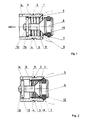
- the safety closing device for gas lines shown in FIG. 1 consists of a tubular valve seat 1, which on its outer diameter is otherwise smaller than the inner diameter of one in different Gas line 26, not shown in the figures, has an annular web 2, the diameter of which in turn is larger than the inner diameter of the gas line 26.
- the annular web 2 is advantageously provided with an insertion bevel 3.
- the valve seat 1 has a circumferential groove 4 on both sides of the ring web 2 in order to achieve better elasticity by means of the increased height of the ring web 2.
- valve body 6 which is movable in the axial direction and which has an annular receptacle for a round ring 7 serving as an elastic sealing element owns.
- the valve body 6 and the round ring 7 are dimensionally fixed so that the outside diameter of the valve body 6 without the round ring 7 is smaller than the associated inside diameter of the valve seat 1, while the outside diameter of the valve body 6 with the mounted round ring 7 is larger than this inside diameter.
- a spring 8 which is designed as a compression spring and holds the valve body 6 in the open position, is supported, which is supported with its other end on a circumferential shoulder 9, which is attached to the inner diameter of the valve body 6 Valve seat 1 connects.
- the valve body 6 has a circumferential collar 10, to which a pin 11 is connected in the flow direction.
- the pin 11 has a through bore 12 which serves to receive a locking element 13, in this case a pin (FIG. 1).
- FIG. 4 A somewhat different embodiment is shown in FIG. 4.
- the pin 11 is provided with a thread, and a wire bracket 15, which is designed so that it can be screwed onto the pin 11 (FIG. 5), serves as the blocking element 13.
- valve body 6 shows a further embodiment.
- This solution differs from the previous one in that the valve body 6 and the pin 11 consist of two separate parts, the valve body 6 having an axial threaded bore 16 with which it is screwed onto the threaded pin 11 located in the flow direction to which the locking element 13, which is supported on the shoulder 9 of the valve seat 1, is rigidly attached.
- a specialist means between the pin 11 and the bore 16 such as, for example, a commercially available PTFE tape 17 in this case.
- An elastic sealing element has been dispensed with in this embodiment.
- the valve body 6 was designed spherical, while the sealing surface 5 is designed as a slope.
- the valve body 6 also has a recess 27.
- the ring web 2 located at the end of the valve seat 1 is designed to be significantly stronger than in the exemplary embodiments described above, and it also has an insertion bevel 3.
- This shape of the valve seat 1 is particularly suitable for installation in gas pipes consisting of PE pipe, as is indicated in FIG. 7 in FIG. 7.
- the security locking device is installed in this case, for example, by heating the gas line 26 consisting of PE pipe.
- the yielding part in this case is not the ring web 2, but the gas line 26.
- the valve body consists of a plate 18 floating freely on the spring 8, which in the open position is supported against a stop which can be elastically deformed in the radial direction.
- the stop consists of a spreading spring 20 which is snapped into a circumferential inner groove 19 of the valve seat 1.
- the stop is formed by a slotted circular ring 24, which preferably has three webs 25 projecting radially inwards and uniformly distributed over the circumference. It is only important to ensure that the area of the stop reducing the flow cross section is kept as small as possible.
- a round ring 7 located on the plate 18 is used to achieve the desired tightness, while the sealing surface 5 of the valve seat 1 is again designed in the form of a hollow ball.
- the plate 18 Since gas pipes made of PE pipe are usually buried pipes, so that the safety locking device is difficult to access, the plate 18 has a leak hole 23, which leads to a defined and of course permissible leakage flow, whereby after an accident which has led to the closing of the safety locking device, the latter opens again.
- the security locking device already described in FIG. 7 has been modified such that the support shoulder 21, which is designed as a separate part, is connected to the valve seat 1 via a thread 22 and can thus be adjusted in the axial direction. This enables an adjustment that does not require a change in the flow cross section.
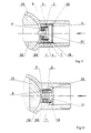
- FIGS. 11 and 12 The use of a security locking device according to the invention in connection with a commercially available gas shut-off valve 29 is shown in FIGS. 11 and 12. 11, the safety closing device is inserted into the gas inlet of the gas shut-off valve 29, in FIG. 12 the valve seat 1 is made in one piece with the gas inlet of the gas shut-off valve 29.
- the plate 18 of the security locking device has on its side facing the spring 8 in the axial direction a peg-shaped extension 28 which projects out of the same when the security locking device is closed (FIG. 11), but is located within the same when the security locking device is open.
- the safety closing device is arranged so far in the gas inlet that the peg-shaped extension 28 projects into the pivoting range of the closing member 32 of the gas shut-off valve 29 when the safety closing device is closed.
- the gas shut-off valve 29 is closed, which usually takes place in the event of an accident, the peg-shaped extension 28, the end of which is shaped accordingly, is displaced in the axial direction (FIG. 12), as a result of which the safety closing device is opened completely again due to the spring 8 acting is, so that the gas can flow again after the opening of the gas shut-off valve 29 after elimination of the accident.
- FIGS. A safety locking device provided for this case is shown in FIGS. While the safety locking device is inserted into the electric welding sleeve 30 in FIG. 13, the valve seat 1 is embodied in one piece with the same in FIG.
- the circular ring 24 visible in FIG. 9, which serves as a stop has, in addition to the webs 25, teeth 34 distributed on the outer circumference which press into the electric welding sleeve 30.
- the inside diameter of the safety closing device can be increased since it is located outside the gas line 26, whereby the pressure loss caused by the safety closing device can be minimized.
- the safety closing device has a stepped collar 31 at its downstream end, the flow cross section of which is otherwise larger than the flow cross section in the plate region, the outer diameter of the collar 31 being smaller than the inner diameter of the gas line 26.
Abstract
Description
Die Erfindung betrifft eine Sicherheitsschließvorrichtung für Gasleitungen mit einem Ventilkörper und einem Ventilsitz nach dem Oberbegriff des ersten Patentanspruches.The invention relates to a safety closing device for gas lines with a valve body and a valve seat according to the preamble of the first claim.
Derartige Sicherheitsschließvorrichtungen dienen dazu, bei Havarien, zum Beispiel bei Rohrbrüchen oder Schlauchrissen, die Gasleitung zu verschließen, um ein unkontrolliertes Ausströmen des Gases und damit eine Gefährdung zu verhindern.Such safety locking devices serve to close the gas line in the event of an accident, for example in the event of pipe breaks or hose tears, in order to prevent an uncontrolled outflow of the gas and thus a hazard.
Es sind bereits Sicherheitsschließvorrichtungen bekannt geworden, welche zwischen der Zuleitung und einem Verbraucher angeordnet sind, und die sicherstellen sollen, daß zum Beispiel bei einem Rohrbruch oder bei einem Platzen eines Schlauches ein Verschließen der Zuleitung erfolgt.Safety locking devices are already known which are arranged between the feed line and a consumer and which are intended to ensure that the feed line is closed, for example in the event of a pipe break or a hose bursting.
So ist aus der US-PS 4,830,046 eine Sicherheitsschließvorrichtung bekannt, bei der in einem, beidseitig ein Anschlußgewinde aufweisenden Gehäuse ein als Kugel ausgebildeter Ventilkörper gegen einen Ventilsitz preßbar ist, wobei der Ventilkörper in Achsrichtung des Ventilsitzes entgegen der Kraft einer Feder in Schließrichtung verschiebbar ist. Während sich der Ventilkörper in Offenstellung unter der Einwirkung der Feder an einem Anschlag abstützt, wird er während seiner Schließbewegung nur durch diese Feder geführt.For example, a security locking device is known from US Pat. No. 4,830,046, in which a valve body designed as a ball can be pressed against a valve seat in a housing having a connection thread on both sides, the valve body being displaceable in the axial direction of the valve seat against the force of a spring in the closing direction. While the valve body is supported in the open position under the action of the spring against a stop, it is only guided by this spring during its closing movement.
Bei dieser Lösung ist es von Nachteil, daß einmal durch das als Anschlag für den Ventilkörper in Offenstellung dienende Einschraubteil, sowie auch durch eine zweite ebenfalls als Einschraubteil ausgebildete Auflage für die Feder Drosselstellen entstehen, die einen zusätzlichen Druckverlust erzeugen. Um die gewünschte Durchflußmenge zu gewährleisten muß somit ein größeres Bauvolumen in Kauf genommen werden. Damit ist es weiterhin von Nachteil, daß durch das Einfügen des Ventils in die Gasleitung zwei neue Dichtstellen zum Raum hin entstehen, und daß bei einer Kombination der Sicherheitsvorrichtung mit einer anderen Armatur, zum Beispiel einem Schlauchhahn, deren Baulänge vergrößert wird. Bei Nachrüstungen in vorhandene Anlagen ist es notwendig, die vorhandene Gasleitung entsprechend zu kürzen.In this solution it is disadvantageous that once serving as a stop for the valve body in the open position Screw-in part, as well as throttling points, which also generate a additional pressure loss, are formed by a second support for the spring, which is also designed as a screw-in part. To ensure the desired flow rate, a larger construction volume must be accepted. It is also a disadvantage that two new sealing points are created towards the room by inserting the valve into the gas line, and that when the safety device is combined with another fitting, for example a hose valve, the overall length of the valve is increased. When retrofitting existing systems, it is necessary to shorten the existing gas line accordingly.
Auf Grund der Anschlußgewinde und der Einbauten ergibt sich somit ein insgesamt gesehen aufwendiges Gerät.Due to the connection thread and the internals, this results in an overall complex device.
Eine weitere Sicherheitsschließvorrichtung ist in der WO 92/01184 beschrieben, die bei einer auftretenden Beschädigung des Rohrleitungssystems dieses verschließt, ohne jedoch ein vorzeitiges Verschließen der Zuleitung zu bewirken, wenn ein Verbraucher über einen längeren Zeitraum die seiner Leistung entsprechende Gasmenge benötigt. Bei dieser Sicherheitsschließvorrichtung ist ein Ventil als in Achsrichtung eines rohrförmigen Gehäuses verschiebliches Tellerventil entgegen der Kraft einer Feder verschiebbar gelagert. Dazu sind Scheiben mit mittiger Lagerstelle für das Tellerventil in das Gehäuse eingebracht, die an ihrem Umfang Durchbrüche für die Gasströmung aufweisen. Das Gehäuse besitzt an beiden stirnseitigen Enden Gewinde zur Verbindung mit der Rohrleitung oder anderen Armaturen.A further safety locking device is described in WO 92/01184, which closes the pipeline system in the event of damage, but without causing the supply line to be closed prematurely if a consumer requires the gas quantity corresponding to his output over a longer period of time. In this safety locking device, a valve is mounted as a poppet valve which is displaceable in the axial direction of a tubular housing against the force of a spring. For this purpose, disks with a central bearing point for the poppet valve are introduced into the housing, which have openings for the gas flow on their circumference. The housing has threads at both ends for connection to the pipeline or other fittings.
Bei dieser Lösung ist es von Nachteil, daß die Bewegung des Ventiltellers durch Lagerstellen geführt wird. Da die für die Schließbewegung im Havariefall zur Verfügung stehenden Druckkräfte, die dann auf den Ventilteller wirken, nur wenige Millibar betragen, ist die Kraft der Feder, welche den Durchflußwert, bei dem die Sicherheitsschließvorrichtung ansprechen soll, bestimmt, außerordentlich gering. Jede Lagerreibung verfälscht diesen Durchflußwert erheblich und nicht reproduzierbar.In this solution, it is disadvantageous that the movement of the valve plate is carried out through bearings. Since the pressure forces available for the closing movement in the event of an accident, which then act on the valve plate, are only a few millibars, the force of the spring is the Flow rate at which the safety locking device should respond is determined, extremely low. Every bearing friction falsifies this flow value considerably and cannot be reproduced.
Besondes schwerwiegend ist dieser Nachteil unter Berücksichtigung dessen, daß das Ventil im Normalbetrieb nicht betätigt und somit auch keine Bewegung des Ventilschaftes innerhalb der Lager erfolgt, die der Verschmutzung durch den Gasstrom ausgesetzt sind. Der Einsatz solcher Sicherheitsschließvorrichtungen ist jedoch u.a. bei Gasleitungen vorgesehen, welche im Erdreich verlegt werden, was bedeutet, daß sie auch über einen längeren Zeitraum, zum Beispiel mehrere Jahrzehnte, ohne Wartung ihre Sicherheitsfunktion behalten müssen,This disadvantage is particularly serious, taking into account that the valve is not actuated in normal operation and therefore there is no movement of the valve stem within the bearings which are exposed to the contamination by the gas flow. The use of such security locking devices is, among other things. provided for gas lines which are laid in the ground, which means that they must maintain their safety function for a longer period, for example several decades, without maintenance,
Weiterhin ist es von Nachteil, daß durch das Einfügen des Ventils in die Gasleitung zwei neue Dichtstellen zum Raum hin entstehen, und daß bei einer Kombination der Sicherheitsvorrichtung mit einer anderen Armatur, zum Beispiel einem Schlauchhahn, deren Baulänge vergrößert wird. Bei Nachrüstungen in vorhandene Anlagen ist es notwendig, die vorhandene Gasleitung entsprechend zu kürzen.Furthermore, it is disadvantageous that two new sealing points are created towards the room by inserting the valve into the gas line, and that when the safety device is combined with another fitting, for example a hose valve, its overall length is increased. When retrofitting existing systems, it is necessary to shorten the existing gas line accordingly.
Die durchbrochenen Scheiben, die zur Lagerung des Tellerventils dienen, erzeugen desweiteren einen zusätzlichen Druckverlust.The perforated disks, which serve to support the poppet valve, also generate an additional pressure loss.
Auf Grund der Anschlußgewinde und der Einbauten ergibt sich somit auch bei dieser Lösung ein insgesamt gesehen aufwendiges Gerät.Due to the connection thread and the internals, this solution also results in an overall complex device.
Der Erfindung liegt das Problem zugrunde, eine Sicherheitsschließvorrichtung für Gasleitungen zu schaffen, bei der der Vorteil der reibungs- und wartungsfreien Lagerung des Ventilkörpers beibehalten sein soll, und die nur einen minimalen Strömungswiderstand verursacht. Desweiteren soll die Sicherheitsschließvorrichtung ohne nach außen dichtende Verbindungen auskommen. Sie soll leicht montierbar und in vorhandene Gasleitungen oder Armaturen ohne deren Änderung nachrüstbar sein.The invention is based on the problem of creating a safety closing device for gas lines in which the Advantage of the friction and maintenance-free mounting of the valve body should be maintained, and which causes only a minimal flow resistance. Furthermore, the security locking device should manage without connections that seal to the outside. It should be easy to assemble and retrofittable in existing gas lines or fittings without changing them.
Erfindungsgemäß wird das Problem dadurch gelöst, daß der Ventilkörper ein auf der Feder frei schwebender Teller ist, der sich in Offenstellung gegen einen in radialer Richtung elastisch verformbaren Anschlag abstützt, der in eine Nut eingeschnappt ist, die vorzugsweise einstückig mit dem Ventilsitz verbunden ist. Durch das äußerst geringe Gewicht hat diese Lösung insbesondere den Vorteil, daß die in Abhängigkeit von der Einbaulage auftretende Masseeinwirkung, die zum Beispiel Einfluß auf die Auslenkung und die Kräftebilanz und 0 somit auch auf den Schließvorgang hat, sehr gering gehalten ist.According to the invention, the problem is solved in that the valve body is a plate floating freely on the spring, which in the open position is supported against an elastically deformable stop in the radial direction, which is snapped into a groove, which is preferably integrally connected to the valve seat. Due to the extremely low weight, this solution has the particular advantage that the influence of mass, which depends on the installation position and which, for example, has an influence on the deflection and the balance of forces and thus also on the closing process, is kept very low.
Vorteilhafte Ausgestaltungen der Erfindung gehen aus den weiteren Patentansprüchen hervor.Advantageous embodiments of the invention emerge from the further patent claims.
Dabei kann der Anschlag zum Beispiel durch eine Spreizfeder oder einen geschlitzten Kreisring, der vorzugsweise drei auf dem Umfang gleichmäßig verteilte radial nach innen ragende Stege aufweist, gebildet werden, wodurch der Strömungsquerschnitt nur unwesentlich verringert wird.The stop can be formed, for example, by an expansion spring or a slotted circular ring, which preferably has three webs projecting radially inwards evenly distributed over the circumference, whereby the flow cross section is only insignificantly reduced.
Damit ohne eine Veränderung des Strömungsquerschnittes eine Justierung ermöglicht wird, erweist es sich als vorteilhaft, wenn die Auflageschulter des dem Ventilkörper abgewandten Endes der Feder in Achsrichtung stellbar ist, indem sie zum Beispiel mittels eines Gewindes mit dem Ventilsitz verbunden ist. Durch diese verstellbare Auflageschulter ist eine Justagemöglichkeit der Sicherheitsschließvorrichtung gefunden, die ohne eine Veränderung des Strömungsquerschnittes auskommt.So that an adjustment is possible without changing the flow cross-section, it proves to be advantageous if the support shoulder of the end of the spring facing away from the valve body can be adjusted in the axial direction, for example by being connected to the valve seat by means of a thread. This adjustable support shoulder provides an adjustment option for the security locking device, that manages without changing the flow cross-section.
Insbesondere für den Einsatz in Verbindung mit einem handelsüblichen Gasabsperrhahn ist es von Vorteil, wenn die Sicherheitsschließvorrichtung in den Gaseingang des Gasabsperrhahnes eingesetzt wird, wobei der Teller der Sicherheitsschließvorrichtung an seiner der Feder zugewandten Seite in axialer Richtung einen zapfenförmigen Fortsatz aufweist, der bei geschlossener Sicherheitsschließvorrichtung aus derselben hervorragt, sich hingegen bei Offenstellung der Sicherheitsschließvorrichtung innerhalb derselben befindet. Es ist natürlich auch möglich daß der Ventilsitz einstückig mit dem Gaseingang des Gasabsperrhahnes ausgeführt ist. Dabei befindet sich die Sicherheitsschließvorrichtung so weit im Gaseingang, daß der zapfenförmige Fortsatz bei geschlossener Sicherheitsschließvorrichtung in den Schwenkbereich des Schließorgans des Gasabsperrhahnes hineinragt. Bei dieser Lösung kann die Sicherheitsschließvorrichtung vollkommen dicht schließen. Eine Leckflußbohrung zum automatischen Wiederöffnen der Sicherheitsschließvorrichtung ist nicht erforderlich. Mit Schließen des Gasabsperrhahnes, was bei der Behebung von Havarien, zum Beispiel dem Auswechseln eines Schlauches, regelmäßig immer der Fall ist, wird der zapfenförmige Fortsatz in Achsrichtung verschoben, wodurch die Sicherheitsschließvorrichtung wieder geöffnet wird, so daß das Gas nach dem nach Beseitigung der Havarie erfolgten Öffnen des Gasabsperrhahnes wieder strömen kann.In particular for use in conjunction with a commercially available gas shut-off valve, it is advantageous if the safety closing device is inserted into the gas inlet of the gas shut-off valve, the plate of the safety closing device having a peg-shaped extension in the axial direction on its side facing the spring, which extends when the safety closing device is closed protrudes the same, but is located within the same when the security locking device is open. It is of course also possible that the valve seat is made in one piece with the gas inlet of the gas shut-off valve. The safety locking device is located so far in the gas inlet that the peg-shaped extension projects into the pivoting range of the closing element of the gas shut-off valve when the safety locking device is closed. With this solution, the security locking device can close completely tightly. A leak flow hole for automatic reopening of the safety locking device is not necessary. When the gas shut-off valve is closed, which is usually always the case when eliminating accidents, for example changing a hose, the peg-shaped extension is moved in the axial direction, as a result of which the safety closing device is opened again, so that the gas after the accident has been eliminated after opening the gas shut-off valve.
Die Erfindung wird nachstehend an einem Ausführungsbeispiel näher beschrieben. Es zeigen:
- Fig. 1
- eine Sicherheitsschließvorrichtung für Gasleitungen in Offenstellung in geschnittener Darstellung,
- Fig. 2
- eine Sicherheitsschließvorrichtung für Gasleitungen in Schließstellung in geschnittener Darstellung,
- Fig. 3
- eine Sicherheitsschließvorrichtung für Gasleitungen vor der Montage des elastischen Abdichtelementes,
- Fig. 4
- eine Sicherheitsschließvorrichtung für Gasleitungen in einer anderen Ausführung in Offenstellung in geschnittener Darstellung,
- Fig. 5
- eine Ansicht A der Sicherheitsschließvorrichtung aus Fig. 4,
- Fig. 6
- eine Sicherheitsschließvorrichtung für Gasleitungen in einer weiteren Ausführung ohne elastisches Abdichtelement in Offenstellung in geschnittener Darstellung,
- Fig. 7
- eine erfindungsgemäße Sicherheitsschließvorrichtung für Gasleitungen in einer weiteren Ausführung mit einem frei schwebenden Ventilkörper (6) in Offenstellung in geschnittener Darstellung,
- Fig. 8
- eine Ansicht B der erfindungsgemäßen Sicherheitsschließvorrichtung aus Fig. 7,
- Fig. 9
- eine Ansicht B der erfindungsgemäßen Sicherheitsschließvorrichtung aus Fig. 7 mit einem verändertem Anschlag für die Feder,
- Fig.10
- eine justierbare erfindungsgemäße Sicherheitsschließvorrichtung für Gasleitungen in einer weiteren Ausführung in Offenstellung in geschnittener Darstellung,
- Fig.11
- eine in den Gaseingang eines Gasabsperrhahnes eingesetzte erfindungsgemäße Sicherheitsschließvorrichtung für Gasleitungen in Schließstellung,
- Fig.12
- eine in den Gaseingang eines Gasabsperrhahnes integrierte erfindungsgemäße Sicherheitsschließvorrichtung für Gasleitungen in durch den Gasabsperrhahn erzwungener Offenstellung,
- Fig.13
- eine in eine Elektroschweißmuffe eingesetzte erfindungsgemäße Sicherheitsschließvorrichtung für Gasleitungen in Offenstellung,
- Fig.14
- eine in eine Elektroschweißmuffe integrierte erfindungsgemäße Sicherheitsschließvorrichtung für Gasleitungen in Schließstellung,
- Fig.15
- ein Anschlag für die Verwendung in einer Elektroschweißmuffe
- Fig. 1
- a safety locking device for gas lines in the open position in a sectional view,
- Fig. 2
- a safety locking device for gas lines in the closed position in a sectional view,
- Fig. 3
- a safety closing device for gas lines before the elastic sealing element is installed,
- Fig. 4
- a safety closing device for gas lines in another embodiment in the open position in a sectional view,
- Fig. 5
- 4 shows a view A of the security locking device from FIG. 4,
- Fig. 6
- a security locking device for gas lines in a further embodiment without an elastic sealing element in the open position in a sectional view,
- Fig. 7
- A safety closure device according to the invention for gas lines in a further embodiment with a freely floating valve body (6) in the open position in a sectional view,
- Fig. 8
- 7 shows a view B of the security locking device according to the invention from FIG. 7,
- Fig. 9
- 7 shows a view B of the security locking device according to the invention from FIG. 7 with a modified stop for the spring,
- Fig. 10
- an adjustable security locking device according to the invention for gas lines in a further embodiment in the open position in a sectional view,
- Fig. 11
- a safety closing device according to the invention for gas lines in the closed position inserted into the gas inlet of a gas shut-off valve,
- Fig. 12
- a safety closing device according to the invention for gas lines integrated into the gas inlet of a gas shut-off valve in the open position forced by the gas shut-off valve,
- Fig. 13
- a safety locking device for gas lines according to the invention inserted in an electric welding sleeve in the open position,
- Fig. 14
- a safety locking device according to the invention for gas lines in the closed position integrated into an electric welding sleeve,
- Fig. 15
- a stop for use in an electric welding socket
Dabei handelt es sich bei den in Fig. 1 bis 6 dargestellten und weiter unten näher erläuterten Ausführungsbeispielen nicht um die Erfindung an sich, sondern um zusätzliche Informationen zur näheren Erläuterung der dann beschriebenen erfindungsgemäßen Sicherheitsschließvorrichtung für Gasleitungen. Die in der Fig. 1 dargestellte Sicherheitsschließvorrichtung für Gasleitungen besteht aus einem rohrförmigen Ventilsitz 1, der an seinem Außendurchmesser, der ansonsten kleiner als der Innendurchmesser einer in verschiedenen Figuren nicht dargestellten Gasleitung 26 ist, einen Ringsteg 2 aufweist, dessen Durchmesser wiederum größer ist, als der Innendurchmesser der Gasleitung 26. Um ein leichteres Einpressen der Sicherheitsschließvorrichtung in die Gasleitung 26 zu gewährleisten, ist der Ringsteg 2 vorteilhafterweise mit einer Einführungsschräge 3 versehen. Desweiteren erweist es sich als günstig, wenn der Ventilsitz 1 beidseitig des Ringsteges 2 eine umlaufende Rille 4 aufweist, um mittels der vergrößerten Höhe des Ringsteges 2 eine bessere Elastizität zu erreichen.The exemplary embodiments shown in FIGS. 1 to 6 and explained in more detail below are not the invention itself, but additional information for a more detailed explanation of the security locking device for gas lines according to the invention, which is then described. The safety closing device for gas lines shown in FIG. 1 consists of a
An seiner, entgegen der durch einen Pfeil dargestellten Strömungsrichtung befindlichen Stirnseite befindet sich eine in Form einer Hohlkugel ausgebildete Dichtfläche 5. Im Inneren des Ventilsitzes 1 ist ein in axialer Richtung beweglicher Ventilkörper 6 angeordnet, der eine ringförmige Aufnahme für einen als elastisches Abdichtelement dienenden Rundring 7 besitzt. Dabei sind der Ventilkörper 6 und der Rundring 7 maßlich so festgelegt, daß der Außendurchmesser des Ventilkörpers 6 ohne dem Rundring 7 kleiner ist als der ihm zugeordnete Innendurchmesser des Ventilsitzes 1, während der Außendurchmesser des Ventilkörpers 6 mit montiertem Rundring 7 größer als dieser Innendurchmesser ist.On its end face, which is opposite to the direction of flow represented by an arrow, there is a sealing
Auf der in Strömungsrichtung befindlichen Seite des Ventilkörpers 6 stützt sich eine den Ventilkörper 6 in Offenstellung haltende vorzugsweise als Druckfeder ausgebildete Feder 8 ab, die sich mit ihrem anderen Ende an einer umlaufenden Schulter 9 abstützt, die sich an den, dem Ventilkörper 6 zugeordneten Innendurchmesser des Ventilsitzes 1 anschließt.On the side of the
Zur Führung der Feder 8 besitzt der Ventilkörper 6 einen umlaufenden Bund 10, an den sich in Strömungsrichtung ein Zapfen 11 anschließt. An seinem Ende weist der Zapfen 11 eine Durchgangsbohrung 12 auf, die zur Aufnahme eines Sperrelementes 13, in diesem Fall eines Stiftes, dient (Fig. 1).To guide the
Zwischen der Länge des Zapfens 11 und der Länge des sich an die Schulter 9 anschließenden ebenfalls rohrförmigen Endstücks 14 des Ventilsitzes 1 besteht die Beziehung, daß das Sperrelement 13 bei montiertem Rundring 7 und in Schließstellung der Sicherheitsschließvorrichtung (Fig. 2) dieses rohrförmige Endstück 14 nicht verläßt, wohingegen bei fehlendem Rundring 7 der Ventilkörper 6 so weit in den Ventilsitz 1 hineingedrückt werden kann, daß das Sperrelement 13 aus dem Endstück 14 herausragt (Fig. 3).Between the length of the
Eine etwas andere Ausführung ist in Fig. 4 dargestellt. Hierbei ist der Zapfen 11 mit Gewinde versehen, und als Sperrelement 13 dient ein Drahtbügel 15, der so gestaltet ist, daß er auf den Zapfen 11 aufgeschraubt werden kann (Fig. 5).A somewhat different embodiment is shown in FIG. 4. Here, the
In Fig. 6 ist eine weitere Ausführung dargestellt. Diese Lösung unterscheidet sich dadurch von den vorhergehenden, daß der Ventilkörper 6 und der Zapfen 11 aus zwei separaten Teilen bestehen, wobei der Ventilkörper 6 eine axiale mit Gewinde versehene Bohrung 16 aufweist, mit der er auf dem in Strömungsrichtung befindlichen Gewindezapfen 11 aufgeschraubt ist, auf dem das sich an der Schulter 9 des Ventilsitzes 1 abstützende Sperrelement 13 starr befestigt ist. Um die notwendige Abdichtung und gleichzeitig eine Verdrehhemmung zu gewährleisten, befindet sich zwischen dem Zapfen 11 und der Bohrung 16 ein fachübliches Mittel, wie zum Beispiel in diesem Fall ein handelsübliches PTFE-Band 17. Auf ein elastisches Abdichtelement wurde bei dieser Ausführung verzichtet. Zur Erreichung der gewünschten Dichtheit wurde der Ventilkörper 6 kugelförmig gestaltet, während die Dichtfläche 5 als Schräge ausgeführt ist. Zur Aufnahme der Feder 8 und gleichzeitig zur Masseverringerung weist der Ventilkörper 6 desweiteren eine Ausdrehung 27 auf.6 shows a further embodiment. This solution differs from the previous one in that the
Bei einer in Fig. 7 dargestellten erfindungsgemäßen Sicherheitsschließvorrichtung ist der sich am Ende des Ventilsitzes 1 befindliche Ringsteg 2 bedeutend stärker ausgerührt, als bei den weiter oben beschriebenen Ausführungsbeispielen, wobei auch er eine Einführungsschräge 3 aufweist. Diese Form des Ventilsitzes 1 ist besonders für den Einbau in aus PE-Rohr bestehende Gasleitungen, wie sie andeutungsweise unter 26 der Fig. 7 dargestellt ist, geeignet. Die Sicherheitsschließvorrichtung wird hierbei montiert, indem zum Beispiel die aus PE-Rohr bestehende Gasleitung 26 erwärmt wird. Der nachgebende Teil ist in diesem Fall nicht der Ringsteg 2, sondern die Gasleitung 26.In the case of an inventive device shown in FIG. 7 Safety locking device, the
Der Ventilkörper besteht aus einem auf der Feder 8 frei schwebenden Teller 18, der sich in Offenstellung gegen einen in radialer Richtung elastisch verformbaren Anschlag abstützt. Der Anschlag besteht in diesem Ausführungsbeispiel, wie aus Fig. 8 sehr gut zu erkennen ist, aus einer Spreizfeder 20, die in eine umlaufende Innennut 19 des Ventilsitzes 1 eingeschnappt ist.The valve body consists of a
Es versteht sich, daß statt der Spreizfeder 20 auch anders geformte Anschläge verwendet werden können. So wird zum Beispiel in Fig. 9 der Anschlag durch einen geschlitzten Kreisring 24, der vorzugsweise drei auf dem Umfang gleichmäßig verteilte radial nach innen ragende Stege 25 aufweist, gebildet. Darauf zu achten ist nur, daß die den Strömungsquerschnitt verringernde Fläche des Anschlages möglichst klein gehalten wird.It goes without saying that instead of the spreading
Zum Erzielen der gewünschten Dichtheit dient ein auf dem Teller 18 befindlicher Rundring 7, während die Dichtfläche 5 des Ventilsitzes 1 wiederum in Form einer Hohlkugel ausgeführt ist.A
Da es sich bei Gasleitungen aus PE-Rohr üblicherweise um erdverlegte Leitungen handelt, so daß die Sicherheitsschließvorrichtung nur schwer zugänglich ist, besitzt der Teller 18 eine Leckbohrung 23, die zu einem definierten und selbstredend zulässigen Leckfluß führt, wodurch nach dem Beheben einer Havarie, die zum Schließen der Sicherheitsschließvorrichtung geführt hat, diese wieder selbst öffnet.Since gas pipes made of PE pipe are usually buried pipes, so that the safety locking device is difficult to access, the
In Fig. 10 ist die bereits in Fig. 7 beschriebene Sicherheitsschließvorrichtung dahingehend verändert, daß die als separates Teil ausgeführte Auflageschulter 21 über ein Gewinde 22 mit dem Ventilsitz 1 verbunden und somit in Achsrichtung stellbar ist. Damit wird eine Justierung ermöglicht, die ohne eine Veränderung des Strömungsquerschnittes auskommt.In FIG. 10, the security locking device already described in FIG. 7 has been modified such that the
Die Verwendung einer erfindungsgemäßen Sicherheitsschließvorrichtung in Verbindung mit einem handelsüblichen Gasabsperrhahn 29 ist in den Figuren 11 und 12 dargestellt. Während in Fig. 11 die Sicherheitsschließvorrichtung in den Gaseingang des Gasabsperrhahnes 29 eingesetzt ist, ist in Fig. 12 der Ventilsitz 1 einstückig mit dem Gaseingang des Gasabsperrhahnes 29 ausgeführt. Bei beiden Ausführungen weist der Teller 18 der Sicherheitsschließvorrichtung an seiner der Feder 8 zugewandten Seite in axialer Richtung einen zapfenförmigen Fortsatz 28 auf, der bei gescnlossener Sicherheitsschließvorrichtung (Fig. 11) aus derselben hervorragt, sich hingegen bei Offenstellung der Sicherheitsschließvorrichtung innerhalb derselben befindet. Dabei ist die Sicherheitsschließvorrichtung so weit im Gaseingang angeordnet, daß der zapfenförmige Fortsatz 28 bei geschlossener Sicherheitsschließvorrichtung in den Schwenkbereich des Schließorgans 32 des Gasabsperrhahnes 29 hineinragt. Mit Schließen des Gasabsperrhahnes 29, was üblicherweise bei Havarien erfolgt, wird der zapfenförmige Fortsatz 28, dessen Ende entsprechend ausgeformt ist, in Achsrichtung verschoben (Fig. 12), wodurch die Sicherheitsschließvorrichtung auf Grund der wirkenden Feder 8 wieder vollständig geöffnet wird, so daß das Gas nach dem nach Beseitigung der Havarie erfolgten Öffnen des Gasabsperrhahnes 29 wieder strömen kann.The use of a security locking device according to the invention in connection with a commercially available gas shut-off
Bei aus PE-Rohr bestehenden Gasleitungen 26 erfolgt in vielen Fällen die Verbindung mittels sogenannter Elektroschweißmuffen 30. Eine für diesen Fall vorteihafterweise vorgesehene Sicherheitsschließvorrichtung ist in den Figuren 13 und 14 dargestellt. Während in Fig. 13 die Sicherheitsschließvorrichtung in die Elektroschweißmuffe 30 eingesetzt ist, ist in Fig. 14 der Ventilsitz 1 einstückig mit derselben ausgeführt. Um den Anschlag 33 für den Teller 18 einfach zu realisieren, besitzt der in Fig. 9 sichtbare, als Anschlag dienende Kreisring 24. zusätzlich zu den Stegen 25 auf dem äußeren Umfang verteilte Zacken 34, die sich in die Elektroschweißmuffe 30 hineindrücken.In the case of
Wie aus beiden Figuren zu ersehen ist, kann der Innendurchmesser der Sicherheitsschließvorrichtung vergrößert werden, da sie sich außerhalb der Gasleitung 26 befindet, wodurch der durch die Sicherheitsschließvorrichtung hervorgerufene Druckverlust minimiert werden kann.As can be seen from both figures, the inside diameter of the safety closing device can be increased since it is located outside the
Um die Baulängenvergrößerung, die nötig ist, um die an ihren beidseitigen Enden gebrauchte Schweißlänge zur Verbindung mit der Gasleitung 26 zu gewährleisten. gering zu halten. ist es von Vorteil, wenn die Sicherheitsschließvorrichtung an ihrem abströmseitigen Ende, dessen Strömungsquerschnitt ansonsten größer als der Strömungsquerschnitt im Tellerbereich ist, einen abgesetzten Bund 31 aufweist, wobei der Außendurchmesser des Bundes 31 kleiner als der Innendurchmesser der Gasleitung 26 ist.In order to increase the overall length, which is necessary to ensure the welding length used at both ends for connection to the
Es versteht sich, daß die in diesem Abschnitt beschriebenen einzelnen Ausführungen keinen Anspruch auf Vollständigkeit erheben. So ist es zum Beispiel möglich, daß die einzelnen Elemente der weiter oben aufgeführten Beispiele untereinander ausgetauscht werden können, ohne daß der beanspruchte Schutzbereich verlassen wird.It is understood that the individual statements described in this section are not exhaustive. For example, it is possible that the individual Elements of the examples listed above can be interchanged without leaving the claimed scope.
- 11
- VentilsitzValve seat
- 22nd
- RingstegRing bridge
- 33rd
- EinführungsschrägeIntroductory slope
- 44th
- Rillegroove
- 55
- DichtflächeSealing surface
- 66
- VentilkörperValve body
- 77
- AbdichtelementSealing element
- 88th
- Federfeather
- 99
- Schultershoulder
- 1010th
- BundFederation
- 1111
- ZapfenCones
- 1212th
- DurchgangsbohrungThrough hole
- 1313
- SperrelementLocking element
- 1414
- EndstückTail
- 1515
- DrahtbügelWire bracket
- 1616
- Bohrungdrilling
- 1717th
- PTFE-BandPTFE tape
- 1818th
- TellerPlate
- 1919th
- NutGroove
- 2020th
- SpreizfederSpreading spring
- 2121
- AuflageschulterSupport shoulder
- 2222
- Gewindethread
- 2323
- LeckbohrungLeakage
- 2424th
- KreisringCircular ring
- 2525th
- Stegweb
- 2626
- GasleitungGas pipe
- 2727
- AusdrehungRotation
- 2828
- FortsatzContinuation
- 2929
- GasabsperrhahnGas shut-off valve
- 3030th
- ElektroschweißmuffeElectric welding socket
- 3131
- BundFederation
- 3232
- SchließorganLocking device
- 3333
- Anschlagattack
Claims (6)
- Safety sealing device for gas pipes with a valve body (6), which can be pressed against a valve seat (1), whereby the valve body (6) which is guided only by a spring (8) and is otherwise freely moveable without additional support points, and is movable in the axial direction of the valve seat (1) is in the closure direction against the force of a spring (8), characterized by this means in that the valve body (6) is on the spring (8) of freely suspended plate (18) which rests in the open position on a circlip elastically deformable in the radial direction, which is itself latched into a notch (19), which is preferably connected in one piece with the valve seat (1).
- Safety sealing device for gas pipes, according to patent claim 1, characterized by this means in that the circlip is formed by an expanding spring (20).
- Safety sealing device for gas pipes, according to patent claim 1, characterized by this means in that the circlip is formed by a slit circular spring (24) which has three radial flanges (25) extending inwards distributed evenly around its circumference.
- Safety sealing device for gas pipes, according to any of the patent claims 1 to 3, characterized by this means in that the circlip shoulder (21) for the end of the spring (8) facing the valve body (6) is adjustable in the axial direction in which, preferably, it is connected to the valve seat (1) by means of a thread (22).
- Safety sealing device for gas pipes, according to any of the patent claims 1 to 4, characterized by this means in that the plate (18) has a lug-shaped extension (28) on its side facing spring (8) in the axial direction, which protrudes out of the safety sealing device in the closed position and which remains within the same in the open position.
- Safety sealing device for gas pipes, according to patent claim 5, characterized by this means in that the valve seat (1) is constructed in one-piece with the gas inlet of a known gas stopcock (29).
Applications Claiming Priority (7)
| Application Number | Priority Date | Filing Date | Title |
|---|---|---|---|
| DE4300432 | 1993-01-09 | ||
| DE19934300432 DE4300432A1 (en) | 1993-01-09 | 1993-01-09 | Safety shut=off for gas pipes |
| DE9319910U | 1993-12-24 | ||
| PCT/EP1993/003686 WO1994016255A2 (en) | 1993-01-09 | 1993-12-24 | Safety shut-off for gas lines |
| DE4344575 | 1993-12-24 | ||
| DE9319910U DE9319910U1 (en) | 1993-12-24 | 1993-12-24 | Electric welding socket |
| DE4344575A DE4344575A1 (en) | 1993-01-09 | 1993-12-24 | Safety closing device for gas conduits |
Publications (2)
| Publication Number | Publication Date |
|---|---|
| EP0678178A1 EP0678178A1 (en) | 1995-10-25 |
| EP0678178B1 true EP0678178B1 (en) | 1996-12-11 |
Family
ID=27204647
Family Applications (1)
| Application Number | Title | Priority Date | Filing Date |
|---|---|---|---|
| EP94903873A Expired - Lifetime EP0678178B1 (en) | 1993-01-09 | 1993-12-24 | Safety shut-off for gas lines |
Country Status (12)
| Country | Link |
|---|---|
| EP (1) | EP0678178B1 (en) |
| JP (1) | JPH08505212A (en) |
| AT (1) | ATE146263T1 (en) |
| BG (1) | BG99721A (en) |
| CA (1) | CA2152918C (en) |
| FI (1) | FI953367A0 (en) |
| HU (1) | HUT72339A (en) |
| NO (1) | NO952684D0 (en) |
| PL (1) | PL309782A1 (en) |
| RO (1) | RO117730B1 (en) |
| SK (1) | SK87495A3 (en) |
| WO (1) | WO1994016255A2 (en) |
Cited By (10)
| Publication number | Priority date | Publication date | Assignee | Title |
|---|---|---|---|---|
| US8839815B2 (en) | 2011-12-15 | 2014-09-23 | Honeywell International Inc. | Gas valve with electronic cycle counter |
| US8899264B2 (en) | 2011-12-15 | 2014-12-02 | Honeywell International Inc. | Gas valve with electronic proof of closure system |
| US8905063B2 (en) | 2011-12-15 | 2014-12-09 | Honeywell International Inc. | Gas valve with fuel rate monitor |
| US8947242B2 (en) | 2011-12-15 | 2015-02-03 | Honeywell International Inc. | Gas valve with valve leakage test |
| US9074770B2 (en) | 2011-12-15 | 2015-07-07 | Honeywell International Inc. | Gas valve with electronic valve proving system |
| US9234661B2 (en) | 2012-09-15 | 2016-01-12 | Honeywell International Inc. | Burner control system |
| US9557059B2 (en) | 2011-12-15 | 2017-01-31 | Honeywell International Inc | Gas valve with communication link |
| US9995486B2 (en) | 2011-12-15 | 2018-06-12 | Honeywell International Inc. | Gas valve with high/low gas pressure detection |
| US10024439B2 (en) | 2013-12-16 | 2018-07-17 | Honeywell International Inc. | Valve over-travel mechanism |
| US10215291B2 (en) | 2013-10-29 | 2019-02-26 | Honeywell International Inc. | Regulating device |
Families Citing this family (16)
| Publication number | Priority date | Publication date | Assignee | Title |
|---|---|---|---|---|
| US6199584B1 (en) | 1997-12-23 | 2001-03-13 | Whetstone Group International, Inc. | Fluid flow control valve |
| US6263911B1 (en) | 1997-12-23 | 2001-07-24 | Whetstone Group International, Inc. | Fluid flow control valve |
| US6260575B1 (en) | 1997-12-23 | 2001-07-17 | Whetstone Group International, Inc. | Fluid flow control valve |
| NL1011596C1 (en) * | 1998-06-30 | 2000-01-04 | Watts Ocean B V | Flow limiter. |
| DE102004032236B4 (en) * | 2004-07-02 | 2007-08-30 | FITR-Gesellschaft für Innovation im Tief- und Rohrleitungsbau Weimar mbH | Safety shut-off device, namely flow switch |
| US9846440B2 (en) | 2011-12-15 | 2017-12-19 | Honeywell International Inc. | Valve controller configured to estimate fuel comsumption |
| US9835265B2 (en) | 2011-12-15 | 2017-12-05 | Honeywell International Inc. | Valve with actuator diagnostics |
| US9851103B2 (en) | 2011-12-15 | 2017-12-26 | Honeywell International Inc. | Gas valve with overpressure diagnostics |
| US10422531B2 (en) | 2012-09-15 | 2019-09-24 | Honeywell International Inc. | System and approach for controlling a combustion chamber |
| US9841122B2 (en) | 2014-09-09 | 2017-12-12 | Honeywell International Inc. | Gas valve with electronic valve proving system |
| US9645584B2 (en) | 2014-09-17 | 2017-05-09 | Honeywell International Inc. | Gas valve with electronic health monitoring |
| US10503181B2 (en) | 2016-01-13 | 2019-12-10 | Honeywell International Inc. | Pressure regulator |
| US10564062B2 (en) | 2016-10-19 | 2020-02-18 | Honeywell International Inc. | Human-machine interface for gas valve |
| US11073281B2 (en) | 2017-12-29 | 2021-07-27 | Honeywell International Inc. | Closed-loop programming and control of a combustion appliance |
| US10697815B2 (en) | 2018-06-09 | 2020-06-30 | Honeywell International Inc. | System and methods for mitigating condensation in a sensor module |
| US10823206B2 (en) | 2018-07-31 | 2020-11-03 | Emerson Process Management Regulator Technologies, Inc. | Vent limiting device for use with fluid regulators |
Family Cites Families (16)
| Publication number | Priority date | Publication date | Assignee | Title |
|---|---|---|---|---|
| NL80781C (en) * | ||||
| GB556863A (en) * | 1941-05-16 | 1943-10-26 | Acrotorque Co | Improvements relating to automatic shut-off valves |
| US2996077A (en) * | 1958-05-08 | 1961-08-15 | Norman S Blodgett | Check valve |
| FR1204375A (en) * | 1958-10-08 | 1960-01-26 | Cie De Pont Amousson | Flow and pressure regulator |
| FR1409416A (en) * | 1964-07-16 | 1965-08-27 | Tech D Etudes Et Fournitures I | Flow-limiting valve connection |
| DE1600685A1 (en) * | 1967-05-24 | 1970-01-08 | Auto Union Gmbh | Check valve assembly |
| DE2503779A1 (en) * | 1975-01-30 | 1976-08-05 | Bosch Gmbh Robert | DEVICE FOR CLEANING VEHICLE WINDOWS |
| US4105044A (en) * | 1976-11-15 | 1978-08-08 | Ward Aero, Inc. | Flow check valve with bias spring removal capability |
| JPS5917305B2 (en) * | 1978-12-19 | 1984-04-20 | 日信工業株式会社 | Hose with check valve |
| JPS57193489U (en) * | 1981-06-03 | 1982-12-08 | ||
| FR2606454B1 (en) * | 1986-11-06 | 1990-04-20 | Peugeot | NON-RETURN VALVE FOR PRESSURE LIQUID CIRCUIT IN AN INTERNAL COMBUSTION ENGINE, AND ENGINE EQUIPPED WITH SUCH A VALVE |
| DE8705359U1 (en) * | 1987-04-10 | 1987-08-27 | F + H Schweisstechnische Sicherheitsgeraete Gmbh, 5466 Neustadt, De | |
| US4727903A (en) * | 1987-06-26 | 1988-03-01 | Malcolm B. Sturgis | Fluid shutoff valve |
| US4830046A (en) * | 1988-04-22 | 1989-05-16 | Hose Specialties/Capri, Inc. | Excess flow control valve |
| DE8815392U1 (en) * | 1988-12-10 | 1989-03-30 | Schmalz, Kurt, Dr., 7296 Glatten, De | |
| SI9111169B (en) * | 1990-07-06 | 1999-10-31 | Pipelife Rohrsysteme Gesellschaft M.B.H. | Safety closing device |
-
1993
- 1993-12-24 JP JP6515642A patent/JPH08505212A/en active Pending
- 1993-12-24 AT AT94903873T patent/ATE146263T1/en not_active IP Right Cessation
- 1993-12-24 CA CA002152918A patent/CA2152918C/en not_active Expired - Fee Related
- 1993-12-24 WO PCT/EP1993/003686 patent/WO1994016255A2/en active IP Right Grant
- 1993-12-24 PL PL93309782A patent/PL309782A1/en unknown
- 1993-12-24 EP EP94903873A patent/EP0678178B1/en not_active Expired - Lifetime
- 1993-12-24 SK SK874-95A patent/SK87495A3/en unknown
- 1993-12-24 RO RO95-01269A patent/RO117730B1/en unknown
- 1993-12-24 HU HU9502069A patent/HUT72339A/en unknown
-
1995
- 1995-06-14 BG BG99721A patent/BG99721A/en unknown
- 1995-07-06 NO NO952684A patent/NO952684D0/en unknown
- 1995-07-07 FI FI953367A patent/FI953367A0/en not_active Application Discontinuation
Cited By (10)
| Publication number | Priority date | Publication date | Assignee | Title |
|---|---|---|---|---|
| US8839815B2 (en) | 2011-12-15 | 2014-09-23 | Honeywell International Inc. | Gas valve with electronic cycle counter |
| US8899264B2 (en) | 2011-12-15 | 2014-12-02 | Honeywell International Inc. | Gas valve with electronic proof of closure system |
| US8905063B2 (en) | 2011-12-15 | 2014-12-09 | Honeywell International Inc. | Gas valve with fuel rate monitor |
| US8947242B2 (en) | 2011-12-15 | 2015-02-03 | Honeywell International Inc. | Gas valve with valve leakage test |
| US9074770B2 (en) | 2011-12-15 | 2015-07-07 | Honeywell International Inc. | Gas valve with electronic valve proving system |
| US9557059B2 (en) | 2011-12-15 | 2017-01-31 | Honeywell International Inc | Gas valve with communication link |
| US9995486B2 (en) | 2011-12-15 | 2018-06-12 | Honeywell International Inc. | Gas valve with high/low gas pressure detection |
| US9234661B2 (en) | 2012-09-15 | 2016-01-12 | Honeywell International Inc. | Burner control system |
| US10215291B2 (en) | 2013-10-29 | 2019-02-26 | Honeywell International Inc. | Regulating device |
| US10024439B2 (en) | 2013-12-16 | 2018-07-17 | Honeywell International Inc. | Valve over-travel mechanism |
Also Published As
| Publication number | Publication date |
|---|---|
| HU9502069D0 (en) | 1995-08-28 |
| SK87495A3 (en) | 1995-11-08 |
| JPH08505212A (en) | 1996-06-04 |
| NO952684L (en) | 1995-07-06 |
| ATE146263T1 (en) | 1996-12-15 |
| PL309782A1 (en) | 1995-11-13 |
| HUT72339A (en) | 1996-04-29 |
| WO1994016255A2 (en) | 1994-07-21 |
| FI953367A (en) | 1995-07-07 |
| FI953367A0 (en) | 1995-07-07 |
| BG99721A (en) | 1996-04-30 |
| CA2152918C (en) | 2000-06-20 |
| RO117730B1 (en) | 2002-06-28 |
| NO952684D0 (en) | 1995-07-06 |
| EP0678178A1 (en) | 1995-10-25 |
| CA2152918A1 (en) | 1994-07-21 |
| WO1994016255A3 (en) | 1994-09-01 |
Similar Documents
| Publication | Publication Date | Title |
|---|---|---|
| EP0678178B1 (en) | Safety shut-off for gas lines | |
| EP0491027B1 (en) | Safety cut-out | |
| DE10043811A1 (en) | Excess flow valve | |
| EP0605551A1 (en) | Fire-protection valve with shutting spring for automatically shutting off conduits. | |
| EP1516237B1 (en) | Flow rate regulator | |
| EP2011928A2 (en) | Backflow prevention assembly | |
| CH632326A5 (en) | FLOW CONTROL VALVE. | |
| EP1082565B1 (en) | Gas stream monitor | |
| EP0542945B1 (en) | Flow-control valve | |
| DE4344575A1 (en) | Safety closing device for gas conduits | |
| DE102009036201B4 (en) | Excess flow valve | |
| DE3516795A1 (en) | Hose break safety device | |
| DE2500552C2 (en) | SAFETY VALVE FOR PIPE OR BREAKTHROUGH HOSE | |
| EP1590593B1 (en) | Tapping valve having a safety function | |
| DE202009015673U1 (en) | Reducer assembly | |
| EP0883765B1 (en) | Thermal safety device for automatically blocking pipes | |
| EP0709527B1 (en) | Backflow prevention device | |
| EP2252817B1 (en) | Gas flow monitor | |
| DE10156284B4 (en) | Shut-off valve for a flow switch | |
| DE3316579A1 (en) | Pressure-regulating valve | |
| DE2503302A1 (en) | FLOAT CONTROLLED VALVE | |
| DE202004009544U1 (en) | Shut-off device for gas pipe has shut-off valve with valve component installed in passage of shut-off component and preloaded by spring in open position lifted from valve seat | |
| DE10359618B4 (en) | Excess flow valve | |
| DE202009010613U1 (en) | Excess flow valve | |
| DE3212427A1 (en) | SHUT-OFF ORGAN |
Legal Events
| Date | Code | Title | Description |
|---|---|---|---|
| PUAI | Public reference made under article 153(3) epc to a published international application that has entered the european phase |
Free format text: ORIGINAL CODE: 0009012 |
|
| 17P | Request for examination filed |
Effective date: 19950706 |
|
| AK | Designated contracting states |
Kind code of ref document: A1 Designated state(s): AT BE CH DE DK ES FR GB GR IE IT LI NL PT SE |
|
| RBV | Designated contracting states (corrected) |
Designated state(s): AT BE CH DE DK ES FR GB GR IE IT LI NL PT SE |
|
| 17Q | First examination report despatched |
Effective date: 19951017 |
|
| GRAG | Despatch of communication of intention to grant |
Free format text: ORIGINAL CODE: EPIDOS AGRA |
|
| GRAH | Despatch of communication of intention to grant a patent |
Free format text: ORIGINAL CODE: EPIDOS IGRA |
|
| GRAH | Despatch of communication of intention to grant a patent |
Free format text: ORIGINAL CODE: EPIDOS IGRA |
|
| GRAA | (expected) grant |
Free format text: ORIGINAL CODE: 0009210 |
|
| AK | Designated contracting states |
Kind code of ref document: B1 Designated state(s): AT BE CH DE DK ES FR GB GR IE IT LI NL PT SE |
|
| PG25 | Lapsed in a contracting state [announced via postgrant information from national office to epo] |
Ref country code: NL Free format text: LAPSE BECAUSE OF FAILURE TO SUBMIT A TRANSLATION OF THE DESCRIPTION OR TO PAY THE FEE WITHIN THE PRESCRIBED TIME-LIMIT Effective date: 19961211 Ref country code: IT Free format text: LAPSE BECAUSE OF FAILURE TO SUBMIT A TRANSLATION OF THE DESCRIPTION OR TO PAY THE FEE WITHIN THE PRESCRIBED TIME-LIMIT;WARNING: LAPSES OF ITALIAN PATENTS WITH EFFECTIVE DATE BEFORE 2007 MAY HAVE OCCURRED AT ANY TIME BEFORE 2007. THE CORRECT EFFECTIVE DATE MAY BE DIFFERENT FROM THE ONE RECORDED. Effective date: 19961211 Ref country code: GR Free format text: LAPSE BECAUSE OF FAILURE TO SUBMIT A TRANSLATION OF THE DESCRIPTION OR TO PAY THE FEE WITHIN THE PRESCRIBED TIME-LIMIT Effective date: 19961211 Ref country code: GB Effective date: 19961211 Ref country code: FR Effective date: 19961211 Ref country code: ES Free format text: THE PATENT HAS BEEN ANNULLED BY A DECISION OF A NATIONAL AUTHORITY Effective date: 19961211 Ref country code: DK Effective date: 19961211 |
|
| REF | Corresponds to: |
Ref document number: 146263 Country of ref document: AT Date of ref document: 19961215 Kind code of ref document: T |
|
| PG25 | Lapsed in a contracting state [announced via postgrant information from national office to epo] |
Ref country code: LI Effective date: 19961231 Ref country code: CH Effective date: 19961231 Ref country code: BE Effective date: 19961231 |
|
| REF | Corresponds to: |
Ref document number: 59304768 Country of ref document: DE Date of ref document: 19970123 |
|
| REG | Reference to a national code |
Ref country code: IE Ref legal event code: FG4D Free format text: 71009 |
|
| PG25 | Lapsed in a contracting state [announced via postgrant information from national office to epo] |
Ref country code: SE Effective date: 19970311 Ref country code: PT Effective date: 19970311 |
|
| NLV1 | Nl: lapsed or annulled due to failure to fulfill the requirements of art. 29p and 29m of the patents act | ||
| EN | Fr: translation not filed | ||
| GBV | Gb: ep patent (uk) treated as always having been void in accordance with gb section 77(7)/1977 [no translation filed] |
Effective date: 19961211 |
|
| PG25 | Lapsed in a contracting state [announced via postgrant information from national office to epo] |
Ref country code: IE Free format text: LAPSE BECAUSE OF NON-PAYMENT OF DUE FEES Effective date: 19970627 |
|
| REG | Reference to a national code |
Ref country code: IE Ref legal event code: FD4D Ref document number: 71009 Country of ref document: IE |
|
| REG | Reference to a national code |
Ref country code: CH Ref legal event code: PL |
|
| PLBE | No opposition filed within time limit |
Free format text: ORIGINAL CODE: 0009261 |
|
| STAA | Information on the status of an ep patent application or granted ep patent |
Free format text: STATUS: NO OPPOSITION FILED WITHIN TIME LIMIT |
|
| 26N | No opposition filed | ||
| PGFP | Annual fee paid to national office [announced via postgrant information from national office to epo] |
Ref country code: AT Payment date: 20051215 Year of fee payment: 13 |
|
| PG25 | Lapsed in a contracting state [announced via postgrant information from national office to epo] |
Ref country code: AT Free format text: LAPSE BECAUSE OF NON-PAYMENT OF DUE FEES Effective date: 20061224 |
|
| PGFP | Annual fee paid to national office [announced via postgrant information from national office to epo] |
Ref country code: DE Payment date: 20101222 Year of fee payment: 18 |
|
| REG | Reference to a national code |
Ref country code: DE Ref legal event code: R119 Ref document number: 59304768 Country of ref document: DE Effective date: 20130702 |
|
| PG25 | Lapsed in a contracting state [announced via postgrant information from national office to epo] |
Ref country code: DE Free format text: LAPSE BECAUSE OF NON-PAYMENT OF DUE FEES Effective date: 20130702 |